WO2023190870A1 - リチウム二次電池 - Google Patents
リチウム二次電池 Download PDFInfo
- Publication number
- WO2023190870A1 WO2023190870A1 PCT/JP2023/013183 JP2023013183W WO2023190870A1 WO 2023190870 A1 WO2023190870 A1 WO 2023190870A1 JP 2023013183 W JP2023013183 W JP 2023013183W WO 2023190870 A1 WO2023190870 A1 WO 2023190870A1
- Authority
- WO
- WIPO (PCT)
- Prior art keywords
- negative electrode
- electrode
- lithium
- positive electrode
- base material
- Prior art date
- Legal status (The legal status is an assumption and is not a legal conclusion. Google has not performed a legal analysis and makes no representation as to the accuracy of the status listed.)
- Ceased
Links
Images


Classifications
-
- H—ELECTRICITY
- H01—ELECTRIC ELEMENTS
- H01M—PROCESSES OR MEANS, e.g. BATTERIES, FOR THE DIRECT CONVERSION OF CHEMICAL ENERGY INTO ELECTRICAL ENERGY
- H01M4/00—Electrodes
- H01M4/02—Electrodes composed of, or comprising, active material
- H01M4/13—Electrodes for accumulators with non-aqueous electrolyte, e.g. for lithium-accumulators; Processes of manufacture thereof
- H01M4/134—Electrodes based on metals, Si or alloys
-
- H—ELECTRICITY
- H01—ELECTRIC ELEMENTS
- H01M—PROCESSES OR MEANS, e.g. BATTERIES, FOR THE DIRECT CONVERSION OF CHEMICAL ENERGY INTO ELECTRICAL ENERGY
- H01M10/00—Secondary cells; Manufacture thereof
- H01M10/04—Construction or manufacture in general
- H01M10/0431—Cells with wound or folded electrodes
-
- H—ELECTRICITY
- H01—ELECTRIC ELEMENTS
- H01M—PROCESSES OR MEANS, e.g. BATTERIES, FOR THE DIRECT CONVERSION OF CHEMICAL ENERGY INTO ELECTRICAL ENERGY
- H01M10/00—Secondary cells; Manufacture thereof
- H01M10/05—Accumulators with non-aqueous electrolyte
- H01M10/052—Li-accumulators
-
- H—ELECTRICITY
- H01—ELECTRIC ELEMENTS
- H01M—PROCESSES OR MEANS, e.g. BATTERIES, FOR THE DIRECT CONVERSION OF CHEMICAL ENERGY INTO ELECTRICAL ENERGY
- H01M10/00—Secondary cells; Manufacture thereof
- H01M10/05—Accumulators with non-aqueous electrolyte
- H01M10/058—Construction or manufacture
- H01M10/0587—Construction or manufacture of accumulators having only wound construction elements, i.e. wound positive electrodes, wound negative electrodes and wound separators
-
- H—ELECTRICITY
- H01—ELECTRIC ELEMENTS
- H01M—PROCESSES OR MEANS, e.g. BATTERIES, FOR THE DIRECT CONVERSION OF CHEMICAL ENERGY INTO ELECTRICAL ENERGY
- H01M4/00—Electrodes
- H01M4/02—Electrodes composed of, or comprising, active material
- H01M4/36—Selection of substances as active materials, active masses, active liquids
- H01M4/38—Selection of substances as active materials, active masses, active liquids of elements or alloys
-
- H—ELECTRICITY
- H01—ELECTRIC ELEMENTS
- H01M—PROCESSES OR MEANS, e.g. BATTERIES, FOR THE DIRECT CONVERSION OF CHEMICAL ENERGY INTO ELECTRICAL ENERGY
- H01M4/00—Electrodes
- H01M4/02—Electrodes composed of, or comprising, active material
- H01M4/64—Carriers or collectors
- H01M4/66—Selection of materials
- H01M4/669—Steels
-
- H—ELECTRICITY
- H01—ELECTRIC ELEMENTS
- H01M—PROCESSES OR MEANS, e.g. BATTERIES, FOR THE DIRECT CONVERSION OF CHEMICAL ENERGY INTO ELECTRICAL ENERGY
- H01M50/00—Constructional details or processes of manufacture of the non-active parts of electrochemical cells other than fuel cells, e.g. hybrid cells
- H01M50/10—Primary casings; Jackets or wrappings
- H01M50/102—Primary casings; Jackets or wrappings characterised by their shape or physical structure
- H01M50/107—Primary casings; Jackets or wrappings characterised by their shape or physical structure having curved cross-section, e.g. round or elliptic
-
- H—ELECTRICITY
- H01—ELECTRIC ELEMENTS
- H01M—PROCESSES OR MEANS, e.g. BATTERIES, FOR THE DIRECT CONVERSION OF CHEMICAL ENERGY INTO ELECTRICAL ENERGY
- H01M50/00—Constructional details or processes of manufacture of the non-active parts of electrochemical cells other than fuel cells, e.g. hybrid cells
- H01M50/40—Separators; Membranes; Diaphragms; Spacing elements inside cells
- H01M50/409—Separators, membranes or diaphragms characterised by the material
- H01M50/431—Inorganic material
- H01M50/434—Ceramics
-
- H—ELECTRICITY
- H01—ELECTRIC ELEMENTS
- H01M—PROCESSES OR MEANS, e.g. BATTERIES, FOR THE DIRECT CONVERSION OF CHEMICAL ENERGY INTO ELECTRICAL ENERGY
- H01M50/00—Constructional details or processes of manufacture of the non-active parts of electrochemical cells other than fuel cells, e.g. hybrid cells
- H01M50/40—Separators; Membranes; Diaphragms; Spacing elements inside cells
- H01M50/409—Separators, membranes or diaphragms characterised by the material
- H01M50/443—Particulate material
-
- H—ELECTRICITY
- H01—ELECTRIC ELEMENTS
- H01M—PROCESSES OR MEANS, e.g. BATTERIES, FOR THE DIRECT CONVERSION OF CHEMICAL ENERGY INTO ELECTRICAL ENERGY
- H01M50/00—Constructional details or processes of manufacture of the non-active parts of electrochemical cells other than fuel cells, e.g. hybrid cells
- H01M50/40—Separators; Membranes; Diaphragms; Spacing elements inside cells
- H01M50/409—Separators, membranes or diaphragms characterised by the material
- H01M50/446—Composite material consisting of a mixture of organic and inorganic materials
-
- H—ELECTRICITY
- H01—ELECTRIC ELEMENTS
- H01M—PROCESSES OR MEANS, e.g. BATTERIES, FOR THE DIRECT CONVERSION OF CHEMICAL ENERGY INTO ELECTRICAL ENERGY
- H01M50/00—Constructional details or processes of manufacture of the non-active parts of electrochemical cells other than fuel cells, e.g. hybrid cells
- H01M50/40—Separators; Membranes; Diaphragms; Spacing elements inside cells
- H01M50/409—Separators, membranes or diaphragms characterised by the material
- H01M50/449—Separators, membranes or diaphragms characterised by the material having a layered structure
- H01M50/451—Separators, membranes or diaphragms characterised by the material having a layered structure comprising layers of only organic material and layers containing inorganic material
-
- H—ELECTRICITY
- H01—ELECTRIC ELEMENTS
- H01M—PROCESSES OR MEANS, e.g. BATTERIES, FOR THE DIRECT CONVERSION OF CHEMICAL ENERGY INTO ELECTRICAL ENERGY
- H01M50/00—Constructional details or processes of manufacture of the non-active parts of electrochemical cells other than fuel cells, e.g. hybrid cells
- H01M50/40—Separators; Membranes; Diaphragms; Spacing elements inside cells
- H01M50/409—Separators, membranes or diaphragms characterised by the material
- H01M50/449—Separators, membranes or diaphragms characterised by the material having a layered structure
- H01M50/454—Separators, membranes or diaphragms characterised by the material having a layered structure comprising a non-fibrous layer and a fibrous layer superimposed on one another
-
- H—ELECTRICITY
- H01—ELECTRIC ELEMENTS
- H01M—PROCESSES OR MEANS, e.g. BATTERIES, FOR THE DIRECT CONVERSION OF CHEMICAL ENERGY INTO ELECTRICAL ENERGY
- H01M50/00—Constructional details or processes of manufacture of the non-active parts of electrochemical cells other than fuel cells, e.g. hybrid cells
- H01M50/40—Separators; Membranes; Diaphragms; Spacing elements inside cells
- H01M50/463—Separators, membranes or diaphragms characterised by their shape
-
- H—ELECTRICITY
- H01—ELECTRIC ELEMENTS
- H01M—PROCESSES OR MEANS, e.g. BATTERIES, FOR THE DIRECT CONVERSION OF CHEMICAL ENERGY INTO ELECTRICAL ENERGY
- H01M50/00—Constructional details or processes of manufacture of the non-active parts of electrochemical cells other than fuel cells, e.g. hybrid cells
- H01M50/40—Separators; Membranes; Diaphragms; Spacing elements inside cells
- H01M50/489—Separators, membranes, diaphragms or spacing elements inside the cells, characterised by their physical properties, e.g. swelling degree, hydrophilicity or shut down properties
- H01M50/491—Porosity
-
- H—ELECTRICITY
- H01—ELECTRIC ELEMENTS
- H01M—PROCESSES OR MEANS, e.g. BATTERIES, FOR THE DIRECT CONVERSION OF CHEMICAL ENERGY INTO ELECTRICAL ENERGY
- H01M4/00—Electrodes
- H01M4/02—Electrodes composed of, or comprising, active material
- H01M2004/026—Electrodes composed of, or comprising, active material characterised by the polarity
- H01M2004/027—Negative electrodes
-
- H—ELECTRICITY
- H01—ELECTRIC ELEMENTS
- H01M—PROCESSES OR MEANS, e.g. BATTERIES, FOR THE DIRECT CONVERSION OF CHEMICAL ENERGY INTO ELECTRICAL ENERGY
- H01M4/00—Electrodes
- H01M4/02—Electrodes composed of, or comprising, active material
- H01M2004/026—Electrodes composed of, or comprising, active material characterised by the polarity
- H01M2004/028—Positive electrodes
-
- Y—GENERAL TAGGING OF NEW TECHNOLOGICAL DEVELOPMENTS; GENERAL TAGGING OF CROSS-SECTIONAL TECHNOLOGIES SPANNING OVER SEVERAL SECTIONS OF THE IPC; TECHNICAL SUBJECTS COVERED BY FORMER USPC CROSS-REFERENCE ART COLLECTIONS [XRACs] AND DIGESTS
- Y02—TECHNOLOGIES OR APPLICATIONS FOR MITIGATION OR ADAPTATION AGAINST CLIMATE CHANGE
- Y02E—REDUCTION OF GREENHOUSE GAS [GHG] EMISSIONS, RELATED TO ENERGY GENERATION, TRANSMISSION OR DISTRIBUTION
- Y02E60/00—Enabling technologies; Technologies with a potential or indirect contribution to GHG emissions mitigation
- Y02E60/10—Energy storage using batteries
-
- Y—GENERAL TAGGING OF NEW TECHNOLOGICAL DEVELOPMENTS; GENERAL TAGGING OF CROSS-SECTIONAL TECHNOLOGIES SPANNING OVER SEVERAL SECTIONS OF THE IPC; TECHNICAL SUBJECTS COVERED BY FORMER USPC CROSS-REFERENCE ART COLLECTIONS [XRACs] AND DIGESTS
- Y02—TECHNOLOGIES OR APPLICATIONS FOR MITIGATION OR ADAPTATION AGAINST CLIMATE CHANGE
- Y02P—CLIMATE CHANGE MITIGATION TECHNOLOGIES IN THE PRODUCTION OR PROCESSING OF GOODS
- Y02P70/00—Climate change mitigation technologies in the production process for final industrial or consumer products
- Y02P70/50—Manufacturing or production processes characterised by the final manufactured product
Definitions
- the present disclosure relates to a lithium secondary battery.
- a lithium secondary battery (lithium metal secondary battery) includes a wound electrode group and a nonaqueous electrolyte.
- a wound type electrode group is constructed by spirally winding a positive electrode and a negative electrode including a negative electrode current collector with a separator in between.
- lithium metal is deposited on the negative electrode during charging, dissolves during discharge, and is released as lithium ions into the nonaqueous electrolyte.
- Patent Document 1 discloses a cylindrical lithium ion battery in which a positive electrode plate and a negative electrode plate are wound around an axis via a separator to create a wound group, and the wound group is housed in a cylindrical battery container.
- the winding group uses two sets of two stacked separators between the positive electrode plate and the negative electrode plate, and the tip portions of each separator are integrated by welding, and the integrated tip portion
- a cylindrical lithium ion battery has been proposed in which each of the cylindrical lithium ion batteries is joined at a different position on the axis.
- a wound-type electrode group including a positive electrode, a negative electrode including a negative electrode current collector, and a separator disposed between the positive electrode and the negative electrode;
- the negative electrode includes a core member arranged therein and a non-aqueous electrolyte having lithium ion conductivity, in the negative electrode, lithium metal is precipitated during charging, and the lithium metal is dissolved during discharging, and the negative electrode current collector includes:
- This invention relates to a lithium secondary battery made of austenitic stainless steel foil or oxygen-free copper foil.
- the cycle characteristics of a lithium secondary battery can be improved.
- FIG. 1 is a vertical cross-sectional view schematically showing a lithium secondary battery according to an embodiment of the present disclosure.
- FIG. 3 is a diagram schematically showing an example of the configuration of an electrode group.
- FIG. 7 is a diagram schematically showing another example of the configuration of an electrode group.
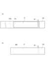
- (a) It is a top view showing an example of a first base material and a negative electrode arranged on the first base material.
- (b) It is a top view showing an example of a negative electrode composite.
- (a) It is a top view which shows an example of a 2nd base material and the positive electrode arrange
- a top view showing an example of a positive electrode composite It is a top view showing an example of a positive and negative electrode laminated body.
- FIG. 1 It is a top view which shows an example of the 1st base material with a convex part, and the negative electrode arrange
- (b) is a top view showing another example of the negative electrode composite.
- FIG. 7 is a top view showing another example of the positive and negative electrode stack.
- FIG. 3 is a top view showing an example of a positive electrode with a convex portion. It is a top view which shows still another example of a positive and negative electrode laminated body.
- a lithium secondary battery includes a wound electrode group and a nonaqueous electrolyte having lithium ion conductivity.
- the wound electrode group includes a positive electrode, a negative electrode including a negative electrode current collector, and a separator disposed between the positive electrode and the negative electrode.
- a core member is arranged in the hollow of the electrode group.
- the negative electrode current collector is an austenitic stainless steel foil or an oxygen-free copper foil.
- a wound type electrode group in which a core member is disposed in a hollow space will also be referred to as an "electrode group with a core member.”
- the lithium secondary battery according to the present disclosure is also referred to as a lithium metal secondary battery.
- a lithium metal secondary battery At the negative electrode of this type of battery, lithium metal precipitates during charging and dissolves during discharge.
- the negative electrode has at least a negative electrode current collector, and lithium metal is deposited on the negative electrode current collector.
- a lithium secondary battery for example, 70% or more of the rated capacity is developed by precipitation and dissolution of lithium metal.
- the movement of electrons in the negative electrode during charging and discharging is mainly due to the precipitation and dissolution of lithium metal in the negative electrode.
- 70 to 100% (for example, 80 to 100% or 90 to 100%) of the movement of electrons (current from another point of view) in the negative electrode during charging and discharging is due to precipitation and dissolution of lithium metal.
- the negative electrode according to the present disclosure is different from a negative electrode in which the movement of electrons in the negative electrode during charging and discharging is mainly caused by occlusion and desorption of lithium ions by a negative electrode active material (such as graphite).
- the open circuit voltage (OCV) of the negative electrode at full charge is, for example, 70 mV or less with respect to lithium metal (lithium dissolution deposition potential).
- Fully charged is a state in which the battery is charged to a state of charge (SOC) of, for example, 0.98 ⁇ C or higher, where C is the rated capacity of the battery.
- SOC state of charge
- the open circuit potential (OCV) of the negative electrode when fully charged can be measured by disassembling a fully charged battery in an argon atmosphere, taking out the negative electrode, and assembling a cell using lithium metal as a counter electrode.
- the non-aqueous electrolyte in the cell may have the same composition as the non-aqueous electrolyte in the disassembled battery.
- the electrode deforms near the hollow part of the electrode group during charging and discharging, resulting in buckling of the electrode, breakage of the electrode, etc.
- the negative electrode undergoes a large volume change during charging and discharging, and is prone to large stress and breakage.
- an electrolytic copper foil or the like is used for the negative electrode current collector, the negative electrode current collector becomes brittle during charging and discharging, and the negative electrode breaks. These deteriorate the cycle characteristics.
- the lithium secondary battery according to the present disclosure by arranging the core member in the hollow part of the electrode group, deformation of the electrode (especially the negative electrode) near the hollow part of the electrode group is suppressed, and the electrode breaks. etc. are suppressed. Furthermore, by using austenitic stainless steel foil or oxygen-free copper foil for the negative electrode current collector, embrittlement of the negative electrode current collector and associated breakage of the negative electrode are suppressed.
- the cycle characteristics are significantly improved.
- a negative electrode current collector whose embrittlement is suppressed, breakage of the negative electrode is suppressed, and by arranging the core member, the shape of the electrode group is significantly stabilized.
- surface pressure is stably applied to the entire electrode group when lithium metal is deposited at the negative electrode, and the formation of lithium metal dendrites is suppressed. Isolation of lithium metal and increase in negative electrode resistance due to dendrite formation are suppressed.
- the effect of applying surface pressure to the entire electrode group during charging and discharging cycles can be easily achieved continuously and stably. As a result, it is estimated that the capacity retention rate during cycling will be significantly increased.
- the electrode group is usually in contact with the inner surface of the battery can during charging and discharging.
- the shape of the electrode group becomes more stable, and surface pressure can be more stably applied to the entire electrode group.
- the relationship between the thickness X of lithium metal deposited on the negative electrode during charging and the distance Y between the positive and negative electrodes during discharging (hereinafter also referred to as "interelectrode distance Y") is Y/X>1.5. It is preferable to satisfy the following.
- the charging time here refers to a time when a large amount of lithium metal is deposited on the negative electrode, for example, when the SOC is 0.9 ⁇ C or more.
- the time of discharge is when a large amount of lithium metal is dissolved from the negative electrode, and refers to, for example, when the SOC is 0.1 ⁇ C or less.
- the above thickness X can also be said to be the difference between the thickness of lithium metal during charging and the thickness of lithium metal during discharging.
- the inter-electrode distance Y can also be said to be the thickness of the separator between the positive and negative electrodes during discharge.
- the thickness of the separator is the total thickness of the plurality of base materials (or a base material and a convex part).
- the positive electrode, negative electrode, and separator each have, for example, a long sheet shape.
- the electrode group with a core member is produced, for example, by winding a positive electrode and a negative electrode around a core member with a separator in between.
- the winding may be performed after the electrode is placed and fixed on a base material (or a base material having a convex portion) constituting the separator, or may be performed after the convex portion is placed on the electrode.
- a core member at a predetermined position of a laminate of a positive electrode, a negative electrode, and a separator (a positive/negative electrode laminate to be described later), and to fix and wind the core member.
- the fixing method is not particularly limited, and examples include methods using tape, adhesive, heat welding, ultrasonic welding, and the like.
- the core member is fixed to the end of the electrode group on the winding start side, and the core member is fixed and arranged in the hollow of the electrode group.
- the shape of the entire electrode group is further stabilized, and buckling or bending of the electrodes near the hollow portion of the electrode group is significantly suppressed.
- surface pressure is easily applied uniformly to the entire electrode group, and the effect of suppressing the formation of lithium metal dendrites can be stably obtained, and the cycle characteristics are further improved.
- the positive electrode and the negative electrode are wound around a predetermined core through a separator, the core is pulled out, an electrode group with a hollow is obtained, and the core member is inserted into the hollow of the electrode group. It may be produced by doing the following. In this case, although the core member is not fixed to the end of the electrode group on the winding start side, the effect of stabilizing the shape of the electrode group can be obtained by arranging the core member.
- the negative electrode current collector is an austenitic stainless steel foil or an oxygen-free copper foil.
- the negative electrode current collector is made of austenitic stainless steel foil, embrittlement of the negative electrode current collector is suppressed, and the negative electrode current collector has appropriate strength and flexibility, and has excellent resistance to stress generated in the negative electrode. ing. Also when using copper foil with a small amount of oxygen, embrittlement of the negative electrode current collector is suppressed.
- the thickness of the negative electrode current collector is not particularly limited, and is, for example, 5 ⁇ m or more and 300 ⁇ m or less.
- Austenitic stainless steel is stainless steel that has an austenite percentage of 50% or more.
- the austenite rate may be 70% or more, 90% or more, or 100%.
- the austenite ratio means the proportion (mass ratio) of the austenite phase in stainless steel.
- the austenite rate is calculated as ⁇ x/(x+y+z) ⁇ 100.
- the austenite structure has a face-centered cubic lattice structure (FCC structure), and the ferrite structure and martensitic structure have a body-centered cubic lattice structure (BCC structure).
- Austenitic stainless steel may contain, for example, C, Si, Mn, P, S, Ni, Cr, Mn, Mo, Cu, N, etc. as components other than Fe.
- the stainless steel may be a low carbon type, an extremely low carbon type, or a nitrogen-added type stainless steel, or may be a duplex stainless steel containing austenite.
- austenitic stainless steel examples include SUS301, SUS302, SUS303, SUS304, SUS305, SUS309, SUS310, SUS312, SUS315, SUS316L, SUS317, SUS321, SUS347, etc. Among them, SUS304 and SUS316L are preferable.
- the austenitic stainless steel is not limited to those exemplified above, and may be any stainless steel with an austenite ratio of 50% or more produced by a melting method. Further, the austenitic stainless steel foil may be a foil softened by annealing.
- the austenite rate can be determined by the following method.
- a stainless steel foil sample for example, size: 25 mm square
- XRD X-ray diffraction
- the size of the measurement area is, for example, 15 mm square.
- the obtained XRD pattern is fitted by the least squares method using a standard database, and then quantitative analysis is performed by Rietveld analysis.
- the XRD pattern may have diffraction peaks corresponding to at least one of an austenite phase, a ferrite phase, and a martensitic phase.
- the analysis can be performed using software attached to the analyzer. Through this analysis, the ratio (mass ratio) of the austenite phase to the total of the austenite phase, ferrite phase, and martensite phase is determined as the austenite ratio.
- Several measurement areas are arbitrarily selected in the sample, the austenite percentage in each measurement area is determined, and their average value is calculated.
- the austenite ratio can also be estimated from Schaeffler's structure diagram, which shows the relationship between ferrite stabilizing elements and austenite stabilizing elements and structures.
- the structure diagram shows the structure ratio with ferrite stabilizing elements and austenite stabilizing elements on both axes.
- the vertical axis of the organization chart shows Ni equivalent, and the horizontal axis shows Cr equivalent.
- Oxygen-free copper foil is copper foil with an oxygen content of 50 ppm or less.
- the oxygen content may be 30 ppm or less, or 15 ppm or less. Note that the oxygen content means the oxygen content in the base material excluding the oxide film covering the surface of the copper foil.
- Oxygen-free copper foil may contain trace amounts of components other than copper (for example, Ni, Cr, Fe, Zn, Sn, Ag, Pb, Bi, Cd, Hg, O, P, S, Se, Te, H, etc.). good.
- the content of Cu in the copper foil may be 99.9% by mass or more, or 99.96% by mass or more.
- the copper foil may be a rolled copper foil. Examples of oxygen-free copper include JIS H3100 and alloy number C1020.
- the oxygen content in copper foil can be determined by the following method.
- a copper foil sample is washed with nitric acid (1+1) for 10 seconds to remove the oxide film on the sample surface. The above washing is repeated until the sample is reduced by 10% by mass or more.
- the sample is washed with distilled water, alcohol, and acetone in this order.
- the sample is dried with hot air and immediately analyzed by inert gas melting/infrared absorption method to determine the oxygen content in the sample.
- an oxygen/nitrogen simultaneous analyzer manufactured by LECO, TC-336) can be used.
- the material of the core member may be a metal material. Among these, stainless steel and nickel-plated carbon steel are preferred from the viewpoint of strength and durability.
- the material of the core member may be a resin material, such as polyester resin (e.g., polyethylene terephthalate, polyethylene naphthalate, polybutylene terephthalate, etc.), olefin resin (e.g., polyethylene, polypropylene, etc.), polyphenylene sulfide resin.
- acrylic resins for example, polymethyl methacrylate, etc.
- polycarbonate resins for example, polyetheretherketone resins, polyethersulfone resins, polyamide resins (for example, aramid resins), polyimide resins, and the like.
- the resin material for the core member may be used alone or in combination of two or more.
- polypropylene, polyethylene, and polyethylene terephthalate are preferable from the viewpoint of electrolyte resistance and the like.
- the shape of the core member may be selected according to the hollow shape of the electrode group.
- the shape of the core member may be cylindrical, preferably cylindrical.
- the cylindrical core member can be expanded and contracted appropriately, and can play a role like a spring. Furthermore, since the cylindrical core member can accommodate the nonaqueous electrolyte in its hollow space, it is possible to improve the retention of the nonaqueous electrolyte in the electrode group.
- the thickness of the material of the core member in the radial direction may be, for example, 0.1 mm or more and 2 mm or less.
- the outer diameter D1 of the core member is, for example, the same as the inner peripheral surface of the electrode group during initial discharge (for example, the first discharge after purchasing the battery or the discharge after several charging and discharging cycles after manufacturing the battery).
- the size may be such that it makes contact with the core member. In this case, at all times from charging to discharging, moderate pressure is applied from the core member to the electrode group from the inner peripheral side, so deformation of the electrodes is suppressed.
- the outer diameter D1 of the core member and the outer diameter D2 of the electrode group during discharge satisfy the relationship D1/D2 ⁇ 1/4.
- D1/D2 is 1/4 or less, the portion that does not contribute to the charge/discharge reaction can be reduced.
- the pressure applied from the core member toward the inner circumferential surface of the electrode group and the pressure applied from the battery can toward the outer circumferential surface of the electrode group each tend to have appropriate magnitudes, and charging The retention of the non-aqueous electrolyte within the electrode group is easily ensured during discharge.
- the inner diameter of the battery can is determined by the outer circumferential surface of the electrode group and the inner circumference of the battery can during initial discharge (for example, the first discharge after purchasing the battery or the discharge after several charging/discharging cycles after manufacturing the battery).
- the size may be such that it makes contact with the surface.
- appropriate pressure is applied from the battery can to the electrode group from the outer peripheral side at all times from charging to discharging, thereby suppressing deformation of the electrodes.
- the outer diameter D2 of the electrode group is approximately the same size as the inner diameter of the battery can.
- the separator may be composed of one base material or a plurality of base materials.
- the base material may be in the form of a sheet.
- the separator may be a laminate of a plurality of sheet base materials, or may be composed of a laminate of base materials and convex portions (spacers).
- a space may be formed between the electrode and the base material by a convex portion (spacer).
- the space may contain lithium metal that is deposited during charging.
- the convex portions may be provided in a plurality of lines along the longitudinal direction of the separator, may be provided in a honeycomb shape, or may be dispersed in a dot shape.
- Examples of the base material include microporous membranes, woven fabrics, nonwoven fabrics, heat-resistant layers, and the like.
- a resin material is used as the material of the microporous membrane, and examples thereof include olefin resin, polyamide resin, polyimide resin, polyester resin, and cellulose resin.
- Examples of the olefin resin include polyethylene, polypropylene, and a copolymer of ethylene and propylene.
- the polyester resin include polyethylene terephthalate.
- glass fibers, olefin resins, polyamide resins, polyimide resins, polyester resins, cellulose resins, etc. are used as the fibrous materials constituting the nonwoven fabric.
- the heat-resistant layer is, for example, a mixed layer of an inorganic material (eg, aluminum oxide, aluminum hydroxide) and a resin material.
- the thickness of the separator is not particularly limited, but is, for example, 10 ⁇ m or more and 80 ⁇ m or less, and may be 20 ⁇ m or more and 70 ⁇ m or less.
- the thickness of the separator is the total thickness of the laminate.
- the separator may include at least one base material selected from the group consisting of microporous sheets (sheet-like microporous membranes) and nonwoven fabric sheets.
- the separator may include a microporous sheet and a heat-resistant layer disposed on at least one surface of the microporous sheet.
- a heat-resistant layer may be disposed between at least one of the positive electrode and the negative electrode and the microporous sheet.
- the heat-resistant layer may be arranged to cover the entire surface of at least one of the microporous sheets, or may be arranged in a line on at least one surface of the microporous sheet.
- a space may be provided between at least one of the positive electrode and the negative electrode and the microporous sheet by the linear heat-resistant layer.
- the heat-resistant layer includes, for example, inorganic particles and a resin material supporting the inorganic particles.
- the resin material include fluorine-containing resins such as polyvinylidene fluoride (PVdF) and polytetrafluoroethylene, fluorine-containing rubbers such as vinylidene fluoride-tetrafluoroethylene copolymer, and aramid resins.
- the inorganic particles include insulating metal oxides. Examples of metal oxides include aluminum oxide (alumina, boehmite, gibbsite), magnesium oxide, titanium oxide (titania), zirconium oxide, silicon oxide (silica), magnesium hydroxide, aluminum hydroxide, and the like.
- the average particle diameter of the inorganic particles is not particularly limited, but is preferably 10 ⁇ m or less, and more preferably 0.1 ⁇ m or more and 2.0 ⁇ m or less.
- the particle size of the inorganic particles is determined by photographing a cross section of the separator using an electron microscope, performing image processing such as binarization to identify the particles, and determining the diameter of an equivalent circle having the same area as the particles.
- the average particle size is determined, for example, by determining the particle diameters of 100 or more particles and averaging them.
- the heat-resistant layer may be formed, for example, by applying a treatment liquid containing a resin material and inorganic particles to the surface of a sheet-like base material, positive electrode, or negative electrode and drying the treatment liquid.
- a treatment liquid containing a resin material and inorganic particles for example, N-methyl-2-pyrrolidone (NMP) is used as the solvent or dispersion medium for the treatment liquid.
- NMP N-methyl-2-pyrrolidone
- the content of the inorganic particles in the heat-resistant layer (treatment liquid) is, for example, 70 parts by mass or more and 100 parts by mass or less per 100 parts by mass of the resin material. In this case, the strength and heat resistance of the heat-resistant layer can be easily ensured.
- the separator may include a base material and a protrusion (spacer).
- a spacer is interposed between at least one of the positive electrode and the negative electrode and the base material.
- a space is formed between at least one of the positive electrode and the negative electrode and the base material.
- the discharge state is a state after a large amount of lithium metal has been dissolved from the negative electrode, and may be, for example, a state of SOC of 0.1 ⁇ C or less.
- the space since the space does not need to be completely filled with lithium metal in the charged state, the space may exist even in the fully charged state, for example.
- the spacer is arranged on at least one selected from the group consisting of the surface of the positive electrode, the surface of the negative electrode, and the surface of the base material.
- the spacer is preferably arranged on the surface of the positive electrode or the surface of the base material on the positive electrode side. In this case, surface pressure from the base material is easily applied to the negative electrode, making it difficult for dendrite-like lithium metal to precipitate, which is advantageous for improving capacity retention during charge/discharge cycles.
- the height of the spacer may be appropriately designed according to the thickness of the base material and the distance between the electrode plates.
- the separator includes a spacer
- the negative electrode has a first region facing the spacer and a second region not facing the spacer.
- the inter-plate space is formed corresponding to the second region.
- the ratio of the area of the first region to the total area of the first region and the second region is not particularly limited, but considering the balance between cycle characteristics and internal resistance, it may be, for example, 5% or more and 30% or less. It may be 5% or more and 20% or less.
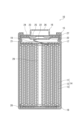
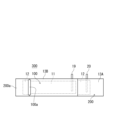
- FIG. 1 is a vertical cross-sectional view schematically showing a cross section parallel to the winding axis of a lithium secondary battery according to an embodiment of the present disclosure.
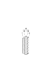
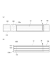
- FIG. 2 is a diagram schematically showing an example of the configuration of an electrode group.
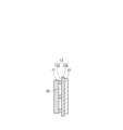
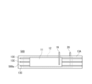
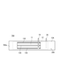
- FIG. 3 is a diagram schematically showing another example of the configuration of the electrode group.
- the battery 10 includes a cylindrical battery case, a wound electrode group 14 housed in the battery case, and a non-aqueous electrolyte (not shown).
- the battery case includes a cylindrical battery can 15 with a bottom and a sealing body 16 that seals the opening of the battery can 15.
- the battery can 15 has an annular step 21 formed by partially pressing the side wall from the outside near the opening.
- the sealing body 16 is supported by the opening side surface of the stepped portion 21 .
- a gasket 27 is disposed between the battery can 15 and the sealing body 16, thereby ensuring the hermeticity of the battery can.
- insulating plates 17 and 18 are arranged at both ends of the electrode group 14 in the winding axis direction, respectively.
- the sealing body 16 includes a filter 22, a lower valve body 23, an insulating member 24, an upper valve body 25, and a cap 26.
- the cap 26 is placed on the outside of the battery can 15, and the filter 22 is placed on the inside of the battery can 15.
- the lower valve body 23 and the upper valve body 25 are connected to each other at their central portions, and an insulating member 24 is interposed between their peripheral edges.
- the filter 22 and the lower valve body 23 are connected to each other at their respective peripheral edges.
- the upper valve body 25 and the cap 26 are connected to each other at their respective peripheral edges.
- a ventilation hole is formed in the lower valve body 23.
- the electrode group 14 is composed of a positive electrode 11, a negative electrode (negative electrode current collector) 12, and a separator 13.
- the positive electrode 11, the negative electrode 12, and the separator 13 interposed between them are all in the form of a long sheet (or band), and are wound so that their respective width directions are parallel to the winding axis.
- a core member 29 is arranged in the hollow of the electrode group 14 .
- the core member 29 in the illustrated example has a cylindrical shape, its shape is not limited to this, and may be, for example, cylindrical.
- the positive electrode 11 includes a positive electrode current collector and a positive electrode composite material layer.
- the positive electrode 11 is electrically connected via a positive electrode lead 19 to a cap 26 that also serves as a positive electrode terminal.
- One end of the positive electrode lead 19 is connected to, for example, near the center of the positive electrode 11 in the longitudinal direction.
- the other end of the positive electrode lead 19 extending from the positive electrode 11 passes through a through hole formed in the insulating plate 17 and is welded to the inner surface of the filter 22 .
- the negative electrode 12 is electrically connected to a battery can 15 which also serves as a negative electrode terminal via a negative electrode lead 20.
- a battery can 15 which also serves as a negative electrode terminal via a negative electrode lead 20.
- One end of the negative electrode lead 20 is connected, for example, to the longitudinal end of the negative electrode 12, and the other end is welded to the inner bottom surface of the battery can 15.
- the separator 13 arranged between the positive electrode 11 and the negative electrode 12 is composed of a sheet-shaped first base material 13A and a second base material 13B.
- the materials of the first base material and the second base material may be the same or different.
- the thickness of the first base material and the second base material may be the same or different.
- the base material is a microporous sheet
- the current can be interrupted by melting the microporous sheet and closing the pores when the battery temperature rises due to a short circuit or the like.
- the base material is a nonwoven fabric sheet, relatively large voids (pores) in the base material can be ensured.
- the separator 13 of the electrode group 14 may be composed of a sheet-shaped first base material 13A and a line-shaped convex portion 13C.
- the first base material 13A may be a microporous sheet
- the convex portions 13C may be a heat-resistant layer.
- the convex portion 13C functions as a spacer, and a space 28 is formed between the positive electrode 11 and the negative electrode 12 by the convex portion 13C.
- the cross-sectional shape of the convex portion 13C is rectangular, but is not limited to this, and may be, for example, trapezoidal.
- the convex portion 13C is provided between the positive electrode 11 and the first base material 13A, but may be provided between the negative electrode 12 and the first base material 13A.
- the plurality of convex portions 13C are They are provided at regular intervals in the width direction of the material 13A. Further, the plurality of convex portions 13C are provided in parallel along the length direction of the first base material 13A.
- the three linear protrusions 13C are arranged in parallel along the length direction of the first base material 13A, but the number of linear protrusions is not limited to this. Further, the arrangement form of the linear convex portions is not limited to this.
- the convex portion may be linear or curved. Further, the convex portions may be provided in a honeycomb shape, for example, or may be arranged in a dot-like manner.
- a space 28 is provided between the positive electrode 11 and the negative electrode 12 by the separator 13 having the convex portion 13C.
- the discharge state lithium metal is not deposited on the surface of the negative electrode current collector, and the space 28 is maintained.
- the charged state lithium metal is deposited on the surface of the negative electrode current collector and is accommodated in the space 28 while being subjected to the pressing force of the first base material 13A.
- the negative electrode 12 includes a negative electrode current collector in a discharged state, and includes a negative electrode current collector and lithium metal deposited on the surface of the negative electrode current collector in a charged state.
- this configuration is only an example, and the negative electrode 12 may include lithium metal on its surface as well as the negative electrode current collector even in the discharge state.
- FIG. 2 which includes a separator 13 composed of a first base material 13A and a second base material 13B, will be described with reference to FIGS. 4 to 6. .
- the band-shaped first base material 13A is folded in half along the width direction at the center in the longitudinal direction, and a crease 130a is formed.
- a negative electrode 12 with a negative electrode lead 19 is prepared, and the negative electrode 12 is placed at a predetermined position on the first base material 13A (FIG. 4(a)).
- the end portion of the negative electrode 12 (the portion not facing the positive electrode) is fixed to the first base material 13A using, for example, double-sided tape 12a or the like.
- the first base material 13A is folded in half to obtain a negative electrode composite 200 in which the first base material 13A is arranged on both sides of the negative electrode 12 (FIG. 4(b)).
- the band-shaped second base material 13B is folded in half along the width direction at the center in the longitudinal direction, and a crease 130b is formed.
- a positive electrode 13 with a positive electrode lead 20 is prepared, and the positive electrode 11 is placed at a predetermined position on the second base material 13B (FIG. 5(a)).
- the second base material 13B is folded in half to obtain a positive electrode composite 100 in which the second base material 13B is arranged on both sides of the positive electrode 11 (FIG. 5(b)).
- double-sided tape 11a is pasted along the fold line 130b of the second base material 130b, and the end of the positive electrode 11 is fixed to the second base material 13B with the double-sided tape 11a.
- the positive electrode composite 100 is placed at a predetermined position on the negative electrode composite 200, and the ends of the positive electrode composite 100 are fixed with tape 100a or the like to obtain a positive and negative electrode stack 300 (FIG. 6).
- a core member is arranged at one end 200a (on the opposite side of the positive electrode composite 100) in the length direction of the positive and negative electrode stack 300 (negative electrode composite 200) and fixed with tape or the like, so that the negative electrode composite 200 is placed inside (
- the positive and negative electrode composites 300 are wound around the core member so that the positive electrode composites 100 are on the outside.
- FIG. 3 which includes a separator 13 composed of a first base material 13A and a linear convex portion 13C, will be described with reference to FIGS. 7 and 8. .
- a convex portion 13C is arranged on one surface of the first base material 13A (FIG. 7(a)). At this time, the convex portion 13C is not arranged in a portion that will be a fold line 130a (a portion to which the core member is attached), which will be described later.
- the first base material 13A is folded in half and a crease 130a is formed.
- the negative electrode 12 is placed at a predetermined position on the other surface of the first base material 13A (FIG. 7(a)).
- the first base material 13A is folded in half to obtain a negative electrode composite 400 in which the first base material 13A having convex portions 13C on both sides of the negative electrode 12 is arranged (FIG. 4(b)).
- the positive electrode 11 is placed at a predetermined position on the negative electrode composite 400 and fixed with an adhesive tape or the like to obtain a positive and negative electrode laminate 500 (FIG. 8).
- a core member is arranged at one end 500a (surface opposite to the positive electrode 11) in the length direction of the positive and negative electrode laminate 500 (negative electrode composite 400) and fixed with tape etc.
- the positive and negative electrode laminate 500 is wound around the core member so that the positive and negative electrodes are on the outside).
- FIGS. 9 and 10 another example of a method for manufacturing an electrode group with a core member having the configuration shown in FIG. explain.
- Convex portions 13C are arranged on both sides of the positive electrode 11 to obtain a positive electrode composite 600 (FIG. 9). At this time, the convex portion 13C is not arranged in the portion where the positive electrode lead 19 is attached.
- the negative electrode composite 200 shown in FIG. 4(b) is prepared, and the positive electrode composite 600 is placed at a predetermined position on the negative electrode composite 200 and fixed with tape or the like to obtain a positive and negative electrode stack 700 (FIG. 10).
- a core member is placed on one end 700a (on the opposite side of the positive electrode composite 600) of the positive and negative electrode stack 700 (negative electrode composite 200) in the length direction, and fixed with tape or the like, and the negative electrode composite 200 is placed inside (
- the positive and negative electrode composites 700 are wound around the core member so that the positive electrode composites 600 are on the outside.
- a cylindrical lithium secondary battery equipped with a wound electrode group has been described, but the shape of the lithium secondary battery is not limited to this, and may be square, and various shapes may be used depending on the purpose. It can be selected as appropriate. Further, known configurations other than those described above can be used without particular restriction.
- the negative electrode includes a negative electrode current collector.
- lithium metal is deposited on the surface of the negative electrode during charging. More specifically, upon charging, lithium ions contained in the nonaqueous electrolyte receive electrons on the negative electrode to become lithium metal, which is deposited on the surface of the negative electrode. Lithium metal deposited on the surface of the negative electrode is dissolved into the nonaqueous electrolyte as lithium ions by discharge.
- the lithium ions contained in the non-aqueous electrolyte may be derived from a lithium salt added to the non-aqueous electrolyte, or may be supplied from the positive electrode active material by charging, and both of these may be derived from the lithium salt added to the non-aqueous electrolyte. There may be.
- the negative electrode may include a negative electrode current collector and a sheet of lithium metal or lithium alloy that is in close contact with the surface of the negative electrode current collector. That is, a base layer containing lithium metal (a layer of lithium metal or lithium alloy (hereinafter also referred to as "lithium base layer”)) may be provided in advance on the negative electrode current collector.
- the lithium alloy may contain elements such as aluminum, magnesium, indium, zinc, copper, and silver.
- the negative electrode may include a lithium ion storage layer (a layer that develops capacity by occluding and releasing lithium ions by a negative electrode active material (such as graphite)) supported on a negative electrode current collector.
- the open circuit potential of the negative electrode at full charge may be 70 mV or less with respect to lithium metal (lithium dissolution deposition potential). If the open circuit potential of the negative electrode at full charge is 70 mV or less with respect to lithium metal, lithium metal is present on the surface of the lithium ion storage layer at full charge. That is, the negative electrode develops capacity due to precipitation and dissolution of lithium metal.
- the lithium ion storage layer is formed by forming a layer of a negative electrode composite material containing a negative electrode active material.
- the negative electrode composite material may also contain a binder, a thickener, a conductive agent, and the like.
- Examples of the negative electrode active material include carbonaceous materials, Si-containing materials, Sn-containing materials, and the like.
- the negative electrode may contain one type of negative electrode active material, or may contain a combination of two or more types.
- Examples of the carbonaceous material include graphite, graphitizable carbon (soft carbon), and non-graphitizable carbon (hard carbon).
- the conductive material is, for example, a carbon material.
- the carbon material include carbon black, acetylene black, Ketjen black, carbon nanotubes, and graphite.
- binder examples include fluororesin, polyacrylonitrile, polyimide resin, acrylic resin, polyolefin resin, rubber-like polymer, and the like.
- fluororesin examples include polytetrafluoroethylene and polyvinylidene fluoride.
- the positive electrode includes, for example, a positive electrode current collector and a positive electrode composite material layer supported by the positive electrode current collector.
- the positive electrode composite material layer includes, for example, a positive electrode active material, a conductive material, and a binding material.
- the positive electrode composite material layer may be formed on only one side of the positive electrode current collector, or may be formed on both sides.
- the positive electrode is obtained, for example, by applying a positive electrode composite slurry containing a positive electrode active material, a conductive material, and a binder to both sides of a positive electrode current collector, drying the coating film, and then rolling the slurry.
- known materials can be used as the positive electrode active material, binder, conductive agent, and the like.
- the positive electrode active material is a material that absorbs and releases lithium ions.
- the positive electrode active material include lithium-containing transition metal oxides, transition metal fluorides, polyanions, fluorinated polyanions, transition metal sulfides, and the like. Among these, lithium-containing transition metal oxides are preferred because of their low manufacturing cost and high average discharge voltage.
- a lithium-containing transition metal oxide is a composite oxide containing lithium and a metal Me other than lithium, where the metal Me includes at least a transition metal.
- the lithium-containing transition metal oxides composite oxides having a rock salt type (layered rock salt type) crystal structure having a layered structure are preferable in terms of obtaining high capacity.
- the metal Me may include Sc, Ti, V, Cr, Mn, Fe, Co, Ni, Cu, Y, Zr, W, etc. as transition metal elements.
- the lithium-containing transition metal oxide may contain one type of transition metal element, or may contain two or more types of transition metal elements.
- the metal Me desirably contains at least one selected from the group consisting of Co, Ni, and Mn as a transition metal element, and desirably contains at least Ni as a transition metal.
- the lithium-containing transition metal oxide may contain one or more typical elements as necessary. Typical elements include Mg, Al, Ca, Zn, Ga, Ge, Sn, Sb, Pb, Bi, and the like.
- the typical element may be Al or the like. That is, the metal Me may contain Al as an optional component.
- the lithium-containing transition metal oxide is represented by, for example, the general formula (1): Li a Ni b M 1-b O 2 .
- general formula (1) 0.9 ⁇ a ⁇ 1.2 and 0.65 ⁇ b ⁇ 1 are satisfied, and M is Co, Mn, Al, Ti, Fe, Nb, B, Mg, Ca, Sr, At least one element selected from the group consisting of Zr and W.
- mLi/mMe The molar ratio of the total amount mLi of Li in the positive electrode and the negative electrode to the amount mMe of metal Me in the lithium-containing transition metal oxide: mLi/mMe is, for example, 1.2 or less, and may be 1.1 or less.
- Examples of the material of the positive electrode current collector include metal materials containing Al, Ti, Fe, and the like.
- the metal material may be Al, Al alloy, Ti, Ti alloy, Fe alloy (stainless steel (SUS), etc.).
- the thickness of the positive electrode current collector is not particularly limited, and is, for example, 5 ⁇ m or more and 300 ⁇ m or less.
- a non-aqueous electrolyte having lithium ion conductivity includes, for example, a non-aqueous solvent, and lithium ions and anions dissolved in the non-aqueous solvent.
- the non-aqueous electrolyte may be in liquid form or gel form.
- a liquid non-aqueous electrolyte is prepared by dissolving a lithium salt in a non-aqueous solvent. Lithium ions and anions are generated by dissolving the lithium salt in a nonaqueous solvent.
- lithium salt or anion known materials used in nonaqueous electrolytes of lithium secondary batteries can be used. Specific examples include BF 4 ⁇ , ClO 4 ⁇ , PF 6 ⁇ , CF 3 SO 3 ⁇ , CF 3 CO 2 ⁇ , imide anions, oxalate complex anions, and the like.
- the anion of the oxalate complex may contain boron and/or phosphorus.
- the non-aqueous electrolyte may contain one or more of these anions.
- the nonaqueous electrolyte preferably contains at least an anion of an oxalate complex, and more preferably an anion of an oxalate complex containing fluorine.
- the interaction between the fluorine-containing oxalate complex anion and lithium facilitates the uniform precipitation of lithium metal in the form of fine particles. Therefore, local precipitation of lithium metal can be easily suppressed.
- the fluorine-containing oxalate complex anion and other anions may be combined. Other anions may be PF 6 - and/or imide anions.
- anions of the oxalate complex include bisoxalate borate anion, difluorooxalate borate anion (BF 2 (C 2 O 4 ) ⁇ ), PF 4 (C 2 O 4 ) ⁇ , PF 2 (C 2 O 4 ) 2 ⁇ etc., and it is desirable to use at least a difluorooxalate borate anion.
- nonaqueous solvent examples include esters, ethers, nitriles, amides, and halogen-substituted products thereof.
- the non-aqueous electrolyte may contain one or more of these non-aqueous solvents.
- halogen-substituted substances include fluorides and the like.
- esters include carbonate esters and carboxylic acid esters.
- examples of the cyclic carbonate include ethylene carbonate, propylene carbonate, fluoroethylene carbonate (FEC), and the like.
- Examples of chain carbonate esters include dimethyl carbonate (DMC), ethylmethyl carbonate (EMC), diethyl carbonate, and the like.
- Examples of the cyclic carboxylic acid ester include ⁇ -butyrolactone and ⁇ -valerolactone.
- chain carboxylic acid esters include ethyl acetate, methyl propionate, methyl fluoropropionate, and the like.
- Ethers include cyclic ethers and chain ethers.
- the cyclic ether include 1,3-dioxolane, 4-methyl-1,3-dioxolane, tetrahydrofuran, and 2-methyltetrahydrofuran.
- the chain ether include 1,2-dimethoxyethane, diethyl ether, ethyl vinyl ether, methylphenyl ether, benzyl ethyl ether, diphenyl ether, dibenzyl ether, 1,2-diethoxyethane, diethylene glycol dimethyl ether, and the like.
- the concentration of the lithium salt in the nonaqueous electrolyte is, for example, 0.5 mol/L or more and 3.5 mol/L or less.
- the concentration of anions in the non-aqueous electrolyte may be 0.5 mol/L or more and 3.5 mol/L or less.
- the concentration of the anion of the oxalate complex in the nonaqueous electrolyte may be 0.05 mol/L or more and 1 mol/L or less.
- austenitic stainless steel foil For the negative electrode current collector, austenitic stainless steel foil, oxygen-free copper foil, or electrolytic copper foil was used. As the austenitic stainless steel foil, SUS316L or SUS304 foil was used. The oxygen-free copper foil used was JIS H 3100 alloy number C1020.
- a strip-shaped first base material 13A shown in FIG. 4(a) was prepared.
- a sheet-like microporous membrane made of polyethylene was used as the first base material 13A.
- the thickness Y1 of the first base material 13A was set to the value shown in Table 1.
- the negative electrode 12 was placed at a predetermined position on the first base material 13A (FIG. 4(a)). At this time, the end portion of the negative electrode 12 (the portion not facing the positive electrode) was fixed to the first base material 13A using double-sided tape 12a. Next, the first base material 13A was folded in half along the fold line 130a to obtain a negative electrode composite 200 in which the first base material 13A was arranged on both sides of the negative electrode 12 (FIG. 4(b)).
- a positive electrode mixture slurry was applied to both sides of a band-shaped Al foil (positive electrode current collector), dried, and the coating film was rolled to obtain a laminate in which positive electrode mixture layers were formed on both sides of the positive electrode current collector. .
- the laminate was cut into a predetermined electrode size to obtain a strip-shaped positive electrode 11.
- a positive electrode lead 19 made of Al was attached to a predetermined position of the positive electrode 11 .
- the filling amount of the positive electrode composite layer (positive electrode active material) was adjusted as appropriate so that the thickness X of lithium metal deposited on the negative electrode current collector during charging was 25 ⁇ m.
- a strip-shaped second base material 13B shown in FIG. 5(a) was prepared.
- As the second base material 13B a sheet-shaped polyethylene microporous membrane or a sheet-shaped polyester nonwoven fabric was used.
- the thickness Y2 of the second base material 13B was set to the value shown in Table 1.
- the positive electrode 11 was placed at a predetermined position on the second base material 13B (FIG. 5(a)). At this time, the end of the positive electrode 11 was fixed to the second base material 13B using double-sided tape 11a. Next, the second base material 13B was folded in half along the fold line 130b to obtain a positive electrode composite 100 in which the second base material 13B was disposed on both sides of the positive electrode 11 (FIG. 5(b)).
- a core member made of SUS304 or polypropylene (PP) was prepared.
- the shape of the core member was cylindrical or cylindrical.
- the outer diameter D1 of the core member was 1.8 mm or 3 mm.
- the outer peripheral surface of the electrode group and the inner peripheral surface of the battery can were in contact, and the outer diameter D2 of the electrode group was a value corresponding to the inner diameter (9 mm) of the battery can.
- the ratio of the outer diameter D1 of the core member to the outer diameter D2 of the electrode group during discharge: D1/D2 was 1/3 or 1/5.
- the positive electrode composite 100 was placed at a predetermined position on the negative electrode composite 200, and the ends of the positive electrode composite 100 were fixed with tape 100a to obtain a positive and negative electrode stack 300.
- the core member 29 was placed on the end 200a (the surface opposite to the positive electrode composite 100) of the positive and negative electrode stack 300 (negative electrode composite 200) and fixed with tape or the like.
- the positive and negative electrode laminate 300 was wound around the core member 29 with the negative electrode composite 200 on the inside (with the positive electrode composite 100 on the outside).
- the electrode group 14 with the core member 29 was constructed.
- the separator 13 was composed of a first base material 13A and a second base material 13B.
- a positive electrode lead 19 and a negative electrode lead 20 were exposed from one end surface of the columnar wound electrode group.
- LiPF 6 and LiBF 2 (C 2 O 4 ) are dissolved in a mixed solvent of 1,2-dimethoxyethane and 1,1,2,2-tetrafluoroethyl-2,2,2-trifluoroethyl ether, respectively, A non-aqueous electrolyte was prepared.
- the concentration of LiPF 6 in the nonaqueous electrolyte was 1 mol/L.
- the concentration of LiBF 2 (C 2 O 4 ) in the nonaqueous electrolyte was 0.1 mol/L.
- the electrode group was inserted into a cylindrical battery can with a bottom, a nonaqueous electrolyte was injected, and the opening of the battery can was sealed with a sealing body. At this time, the positive electrode lead was connected to the sealing body, and the negative electrode lead was connected to the battery can. A gasket was placed between the sealing body and the battery can. In this way, a lithium secondary battery was completed.
- A1 to A2 and A4 to A10 are lithium secondary batteries of Examples 1 to 2 and 4 to 10, respectively.
- B2 and B3 are batteries of Comparative Examples 2 and 3.
- Example 3 The thickness Y1 of the first base material was 40 ⁇ m. A positive electrode was placed at a predetermined position of the negative electrode composite without using the second base material, and a positive and negative electrode laminate was constructed. Battery A3 was obtained in the same manner as Battery A2 of Example 2 except that the above positive and negative electrode laminate was used.
- Example 11 ⁇ (Preparation of spacer ink) A spacer ink was prepared by mixing 90 parts by mass of inorganic particles, 10 parts by mass of polyvinylidene fluoride (PVdF) as a resin material, and N-methyl-2-pyrrolidone as a dispersion medium. Alumina particles (containing alumina with an average particle size of 1 ⁇ m and alumina with an average particle size of 0.1 ⁇ m in a mass ratio of 10/1) were used as the inorganic particles.
- PVdF polyvinylidene fluoride
- first base material with spacer Arrangement of linear convex portion on first base material
- first base material The same first base material as used in Example 6 was prepared as the first base material.
- a spacer ink was applied to one surface (positive electrode side surface) of the first base material using a dispenser and dried with hot air to form linear protrusions (spacers).
- spacers linear protrusions
- FIG. 7(a) on one surface of the first base material 13A, a total of three mutually connected wires are formed along the length direction at both ends and the center in the width direction.
- Parallel linear convex portions 13C (width 1 mm, height 30 ⁇ m) were formed.
- spacer ink was applied intermittently to the portion that would become the crease 130a (the portion where the core member 29 was attached) so as not to form the convex portion 13C.
- the negative electrode 12 was placed at a predetermined position on the other surface (the side on which the convex portion 13C is not formed) of the first base material 13A (FIG. 7(a)).
- the first base material 13A was folded in half, and the first base material 13A with convex portions 13C was placed on both sides of the negative electrode 12 to obtain a negative electrode composite 400 (FIG. 7(b)).
- the positive electrode 11 was placed at a predetermined position on the negative electrode composite 400 and fixed with tape or the like to obtain a positive and negative electrode laminate 500 (FIG. 8).
- the core member 29 was placed at one end 500a (the surface opposite to the positive electrode 11) of the positive and negative electrode stack 500 (negative electrode composite 400) in the length direction, and fixed with tape or the like.
- the positive and negative electrode laminate 500 was wound around the core member 29 so that the negative electrode composite 400 was on the inside (the positive electrode 11 was on the outside).
- the electrode group 14 with the core member 29 was constructed.
- the separator 13 was composed of a first base material 13A and a linear convex portion 13C.
- a battery A11 was obtained in the same manner as the battery A10 of Example 10, except that the electrode group with a core member obtained above was used.
- Example 12 ⁇ (Preparation of positive electrode with spacer: Arrangement of linear convex portion on positive electrode)
- the above spacer ink was applied to both surfaces of the positive electrode using a dispenser and dried with hot air to form linear protrusions (spacers).
- spacers linear protrusions
- FIG. 9 On both surfaces of the positive electrode 11, a total of three parallel linear protrusions are formed along the length direction at both ends and at the center in the width direction.
- a portion 13C (width: 1 mm, height: 30 ⁇ m) was formed.
- spacer ink was applied intermittently to the portion where the positive electrode lead 19 was attached so as not to form a convex portion 13C. In this way, the convex portions 13C were arranged on both sides of the positive electrode 11, and a positive electrode composite 600 was obtained (FIG. 9).
- the negative electrode composite 200 shown in FIG. 4(a) was prepared, and the positive electrode composite 600 was placed at a predetermined position on the negative electrode composite 200 and fixed with tape or the like to obtain a positive and negative electrode laminate 700 (FIG. 10).
- the core member 29 was placed at one end 700a (the surface opposite to the positive electrode composite 600) of the positive and negative electrode stack 700 (negative electrode composite 200) in the length direction, and fixed with tape or the like.
- the positive and negative electrode laminate 700 was wound around the core member 29 so that the negative electrode composite 200 was on the inside (the positive electrode composite 600 was on the outside). In this way, the electrode group 14 with the core member 29 was constructed.
- the separator 13 was composed of a first base material 13A and a linear convex portion 13C.
- a battery A12 was obtained in the same manner as the battery A10 of Example 10, except that the electrode group with a core member obtained above was used.
- Example 13 The thickness Y1 of the first base material was 80 ⁇ m.
- a positive electrode was placed at a predetermined position of the negative electrode composite without using the second base material, and a positive and negative electrode laminate was constructed.
- a battery A13 was obtained in the same manner as the battery A2 of Example 2, except that the above positive and negative electrode laminate was used and the outer diameter D1 of the core member was 1.8 mm.
- Electrolytic copper foil was used as the negative electrode current collector.
- the positive and negative electrode laminate was spirally wound using a winding core to obtain an electrode group, and the winding core was removed to obtain a hollow electrode group. Except for the above, Battery B1 was obtained in the same manner as Battery A10 of Example 10.
- a positive electrode was placed at a predetermined position of the negative electrode composite without using the second base material, and a positive and negative electrode laminate was constructed.
- the positive and negative electrode laminate was spirally wound using a winding core to obtain an electrode group, and the winding core was removed to obtain a hollow electrode group.
- a battery B5 was obtained in the same manner as the battery A1 of Example 1 except for the above.
- the evaluation results are shown in Tables 1 and 2.
- the cycle capacity retention rates in Tables 1 and 2 are expressed as relative values (indexes) when the cycle capacity retention rate of battery B1 of Comparative Example 1 is set to 100.
- Batteries A1 to A13 had higher capacity retention rates than batteries B1 to B5.
- the capacity retention rate increased by about 9% (B1 ⁇ B3) compared to the battery B1 using the electrode group having a hollow space.
- the capacity retention rate increased by about 20% (B1 ⁇ B4) compared to battery B1 using electrolytic copper foil as the negative electrode current collector.
- the capacity retention rate was significantly increased by 60% compared to battery B1 (B1 ⁇ A10).
- the lithium secondary battery of the present disclosure can be used in electronic devices such as mobile phones, smartphones, and tablet terminals, electric vehicles, hybrid vehicles, plug-in hybrid vehicles, household storage batteries, and the like.
Landscapes
- Chemical & Material Sciences (AREA)
- Chemical Kinetics & Catalysis (AREA)
- Electrochemistry (AREA)
- General Chemical & Material Sciences (AREA)
- Engineering & Computer Science (AREA)
- Manufacturing & Machinery (AREA)
- Materials Engineering (AREA)
- Inorganic Chemistry (AREA)
- Composite Materials (AREA)
- Ceramic Engineering (AREA)
- Secondary Cells (AREA)
Abstract
Description
負極集電体はオーステナイト系ステンレス鋼箔または無酸素銅箔である。負極集電体がオーステナイト系ステンレス鋼箔である場合、負極集電体の脆化が抑制され、かつ、負極集電体は適度な強度および柔軟性を有し、負極で生じる応力に対する耐性に優れている。酸素量が小さい銅箔を用いる場合も、負極集電体の脆化が抑制される。負極集電体の厚みは、特に制限されず、例えば、5μm以上、300μm以下である。
ステンレス鋼箔の試料(例えば、サイズ:25mm角)を準備し、当該試料について2次元検出機能を用いるX線回折(XRD)測定を行い、XRDパターン(縦軸:X線回折強度、横軸:回折角2θ)を得る。測定領域(微小部)の大きさは、例えば、15mm角である。
<分析装置>
2次元微小部X線回折装置((株)リガク製、RINT-RAPID II)
<分析条件>
管球:Co
単色化:モノクロメータを使用(CoKα)
管球出力:40kV-30mA
検出器:イメージングプレート(2次元)
(反射法)
コメリータ:Φ300μm
ω角:25°~35°(2°/sec)
Φ角:360°回転(1°/sec)
測定時間(露光):30分
銅箔の試料を硝酸(1+1)で10秒間洗浄し、試料表面の酸化皮膜を除去する。上記洗浄は、試料が10質量%以上減少するまで繰り返し行う。次に、蒸留水、アルコール、およびアセトンの順で、試料の洗浄を行う。次に、試料について、温風による乾燥を行い、直ちに、不活性ガス融解-赤外線吸収法による分析を行い、試料中の酸素含有量を求める。分析装置には、酸素窒素同時分析装置(LECO社製、TC-336)を用いることができる。
電極群の中空に挿入される芯部材には、相当に大きな圧力が充放電に伴って繰り返し印加される。そのため、芯部材の材料には、相当な機械的強度と耐久性が求められる。芯部材の材料は、金属材料であってもよい。中でも、強度および耐久性の観点から、ステンレス鋼、ニッケルめっき炭素鋼が望ましい。また、芯部材の材料は、樹脂材料であってもよく、例えば、ポリエステル樹脂(例えば、ポリエチレンテレフタレート、ポリエチレンナフタレート、ポリブチレンテレフタレート等)、オレフィン樹脂(例えば、ポリエチレン、ポリプロピレン等)、ポリフェニレンスルフィド樹脂、アクリル樹脂(例えば、ポリメタクリル酸メチル等)、ポリカーボネート樹脂、ポリエーテルエーテルケトン樹脂、ポリエーテルスルホン樹脂、ポリアミド樹脂(例えばアラミド樹脂)、ポリイミド樹脂等が挙げられる。芯部材の樹脂材料は、1種を単独で用いてもよく、2種以上を組み合わせて用いてもよい。中でも、耐電解液性等の観点から、ポリプロピレン、ポリエチレン、ポリエチレンテレフタレートが望ましい。
セパレータには、イオン透過性および絶縁性を有する多孔性の基材が用いられる。セパレータは、1つの基材により構成されていてもよく、複数の基材により構成されていてもよい。基材はシート状であればよい。セパレータは、複数のシート基材の積層体であってもよく、基材および凸部(スペーサ)の積層体により構成されていてもよい。凸部(スペーサ)により電極と基材との間に空間が形成されていてもよい。当該空間に、充電時に析出するリチウム金属が収容されてもよい。凸部は、例えば、セパレータの長手方向に沿った複数のライン状に設けてもよく、ハニカム状に設けてもよく、ドット状に分散配置してもよい。
(負極)
負極は、負極集電体を備える。リチウム二次電池では、負極の表面に、充電によりリチウム金属が析出する。より具体的には、非水電解質に含まれるリチウムイオンが、充電により、負極上で電子を受け取ってリチウム金属になり、負極の表面に析出する。負極の表面に析出したリチウム金属は、放電により非水電解質中にリチウムイオンとして溶解する。なお、非水電解質に含まれるリチウムイオンは、非水電解質に添加したリチウム塩に由来するものであってもよく、充電により正極活物質から供給されるものであってもよく、これらの双方であってもよい。
正極は、例えば、正極集電体と、正極集電体に支持された正極合材層とを備える。正極合材層は、例えば、正極活物質と導電材と結着材とを含む。正極合材層は、正極集電体の片面のみに形成されてもよく、両面に形成されてもよい。正極は、例えば、正極集電体の両面に正極活物質と導電材と結着材とを含む正極合材スラリーを塗布し、塗膜を乾燥させた後、圧延することにより得られる。正極活物質、結着剤、導電剤等としては、例えば、公知の材料を用い得る。
リチウムイオン伝導性を有する非水電解質は、例えば、非水溶媒と、非水溶媒に溶解したリチウムイオンとアニオンとを含んでいる。非水電解質は、液状でもよいし、ゲル状でもよい。液状の非水電解質は、リチウム塩を非水溶媒に溶解させることにより調製される。リチウム塩が非水溶媒中に溶解することにより、リチウムイオンおよびアニオンが生成する。
以下、本開示に係るリチウム二次電池を実施例および比較例に基づいて更に具体的に説明する。ただし、本開示は以下の実施例に限定されるものではない。
(負極の準備)
帯状の負極集電体(厚さ10μm)を準備した。露点がマイナス30度以下のドライ雰囲気中で、負極集電体の両面にリチウム金属箔(厚み30μm)を圧着し、リチウム金属層(下地層)を配置した。このようにして負極12を作製した。負極12の所定位置にNi製の負極リード20を取り付けた。なお、リチウム金属層は、充電時の厚み55μmおよび放電時の厚み30μmであった。すなわち、充電時に負極に析出するリチウム金属の厚みXは、25μmであった。
図4(a)の帯状の第1基材13Aを準備した。第1基材13Aには、シート状のポリエチレン製の微多孔膜を用いた。第1基材13Aの厚みY1は、表1に示す値とした。
第1基材13Aの所定位置に負極12を配置した(図4(a))。このとき、両面テープ12aを用いて負極12の端部(正極と対向しない部分)を第1基材13Aに固定した。次に、折り目130aに沿って第1基材13Aを2つ折りにして、負極12の両面に第1基材13Aが配置された負極複合体200を得た(図4(b))。
正極活物質95質量部に、アセチレンブラック2.5質量部と、ポリフッ化ビニリデン2.5質量部とを加え、さらにN-メチル-2-ピロリドンを適量加えて撹拌し、正極合材スラリーを調製した。正極活物質には、Li、Ni、CoおよびAl(Ni、CoおよびAlの合計に対するLiのモル比は1.0)を含有し、層状構造を有する岩塩型のリチウム含有遷移金属酸化物を用いた。
図5(a)の帯状の第2基材13Bを準備した。第2基材13Bには、シート状のポリエチレン製の微多孔膜またはシート状のポリエステル製の不織布を用いた。第2基材13Bの厚みY2は、表1に示す値とした。
第2基材13Bの所定位置に正極11を配置した(図5(a))。このとき、両面テープ11aを用いて正極11の端部を第2基材13Bに固定した。次に、折り目130bに沿って第2基材13Bを2つ折りにして、正極11の両面に第2基材13Bが配置された正極複合体100を得た(図5(b))。
SUS304製またはポリプロピレン(PP)製の芯部材を準備した。芯部材の形状は、円柱状または円筒状とした。芯部材の外径D1は、1.8mmまたは3mmとした。
初期の放電時において、電極群の外周面と電池缶の内周面が接触し、電極群の外径D2は電池缶の内径(9mm)に相当する値であった。放電時の電極群の外径D2に対する芯部材の外径D1の比:D1/D2は、1/3または1/5であった。
図6に示すように、負極複合体200の所定位置に正極複合体100を配置し、正極複合体100の端部をテープ100aで固定し、正負極積層体300を得た。
1,2-ジメトキシエタンおよび1,1,2,2-テトラフルオロエチル-2,2,2-トリフルオロエチルエーテルの混合溶媒にLiPF6およびLiBF2(C2O4)をそれぞれ溶解させて、非水電解質を調製した。非水電解質中のLiPF6の濃度は1モル/Lとした。非水電解質中のLiBF2(C2O4)の濃度は0.1モル/Lとした。
電極群を有底円筒状の電池缶に挿入し、非水電解質を注入し、封口体で電池缶の開口を封口した。このとき、正極リードを封口体に接続し、負極リードを電池缶に接続した。封口体と電池缶との間にガスケットを配置した。このようにして、リチウム二次電池を完成させた。なお、表1中、A1~A2、A4~A10は、それぞれ実施例1~2、4~10のリチウム二次電池である。表2中、B2~B3は、比較例2~3の電池である。
第1基材の厚みY1は40μmとした。第2基材を用いずに、負極複合体の所定位置に正極を配置し、正負極積層体を構成した。
上記の正負極積層体を用いた以外、実施例2の電池A2と同様にして、電池A3を得た。
(スペーサインクの調製)
無機粒子90質量部と、樹脂材料であるポリフッ化ビニリデン(PVdF)10質量部と、分散媒N-メチル-2-ピロリドンとを混合して、スペーサインクを調製した。無機粒子には、アルミナ粒子(平均粒径1μmのアルミナと平均粒径0.1μmのアルミナとを10/1の質量比で含む)を用いた。
第1基材には、実施例6で用いた第1基材と同じものを準備した。ディスペンサを用いて第1基材の一方の表面(正極側の表面)にスペーサインクを塗布し、熱風乾燥させて、ライン状凸部(スペーサ)を形成した。具体的には、図7(a)に示すように、第1基材13Aの一方の表面において、その幅方向の両端部および中央部に、その長さ方向に沿って、合計3本の互いに平行なライン状凸部13C(幅1mm、高さ30μm)を形成した。このとき、折り目130aとなる部分(芯部材29を取り付ける部分)には凸部13Cを形成しないように、スペーサインクを間欠的に塗布した。
第1基材13Aの他方の表面(凸部13Cを形成しない側)の所定位置に負極12を配置した(図7(a))。第1基材13Aを2つ折りにして、負極12の両面に凸部13C付き第1基材13Aを配置し、負極複合体400を得た(図7(b))。負極複合体400の所定位置に正極11を配置し、テープ等で固定し、正負極積層体500を得た(図8)。正負極積層体500(負極複合体400)の長さ方向の一端部500a(正極11と反対側の表面)に芯部材29を配置し、テープ等で固定した。負極複合体400が内側(正極11が外側)になるように正負極積層体500を芯部材29に巻き付けた。このようにして、芯部材29付き電極群14を構成した。電極群14において、セパレータ13は、第1基材13Aおよびライン状凸部13Cで構成された。
(スペーサ付き正極の作製:ライン状凸部の正極への配置)
ディスペンサを用いて正極の両方の表面に上記スペーサインクを塗布し、熱風乾燥させ、ライン状凸部(スペーサ)を形成した。具体的には、図9に示すように、正極11の両方の表面において、その幅方向の両端部および中央部に、その長さ方向に沿って、合計3本の互いに平行なライン状の凸部13C(幅1mm、高さ30μm)を形成した。このとき、正極リード19を取り付ける部分には凸部13Cを形成しないように、スペーサインクを間欠的に塗布した。このようにして、正極11の両面に凸部13Cを配置し、正極複合体600を得た(図9)。
図4(a)の負極複合体200を準備し、負極複合体200の所定位置に正極複合体600を配置し、テープ等で固定し、正負極積層体700を得た(図10)。正負極積層体700(負極複合体200)の長さ方向の一端部700a(正極複合体600と反対側の表面)に芯部材29を配置し、テープ等で固定した。負極複合体200が内側(正極複合体600が外側)になるように正負極積層体700を芯部材29に巻き付けた。このようにして、芯部材29付き電極群14を構成した。電極群14において、セパレータ13は、第1基材13Aおよびライン状凸部13Cで構成された。
第1基材の厚みY1は80μmとした。第2基材を用いずに、負極複合体の所定位置に正極を配置し、正負極積層体を構成した。
上記の正負極積層体を用い、芯部材の外径D1を1.8mmとした以外、実施例2の電池A2と同様にして、電池A13を得た。
負極集電体に電解銅箔を用いた。正負極積層体を巻き芯を用いて渦巻き状に巻回して電極群を得、巻き芯を取り外し、中空を有する電極群を得た。
上記以外、実施例10の電池A10と同様にして、電池B1を得た。
負極集電体にSUS316箔を用いた。正負極積層体を巻き芯を用いて渦巻き状に巻回して電極群を得、巻き芯を取り外し、中空を有する電極群を得た。
上記以外、実施例10の電池A10と同様にして、電池B4を得た。
第2基材を用いずに、負極複合体の所定位置に正極を配置し、正負極積層体を構成した。正負極積層体を巻き芯を用いて渦巻き状に巻回して電極群を得、巻き芯を取り外し、中空を有する電極群を得た。
上記以外、実施例1の電池A1と同様にして、電池B5を得た。
得られた各電池について、25℃の環境下で充放電サイクル試験を行った。充放電は、以下の条件で行った。充電と放電との間は、20分間の休止を行った。
電池電圧が4.1Vになるまで10mAで定電流充電を行い、その後、電流値が1mAになるまで4.1Vの電圧で定電圧充電を行った。
電池電圧が3.0Vになるまで10mAで定電流放電を行った。
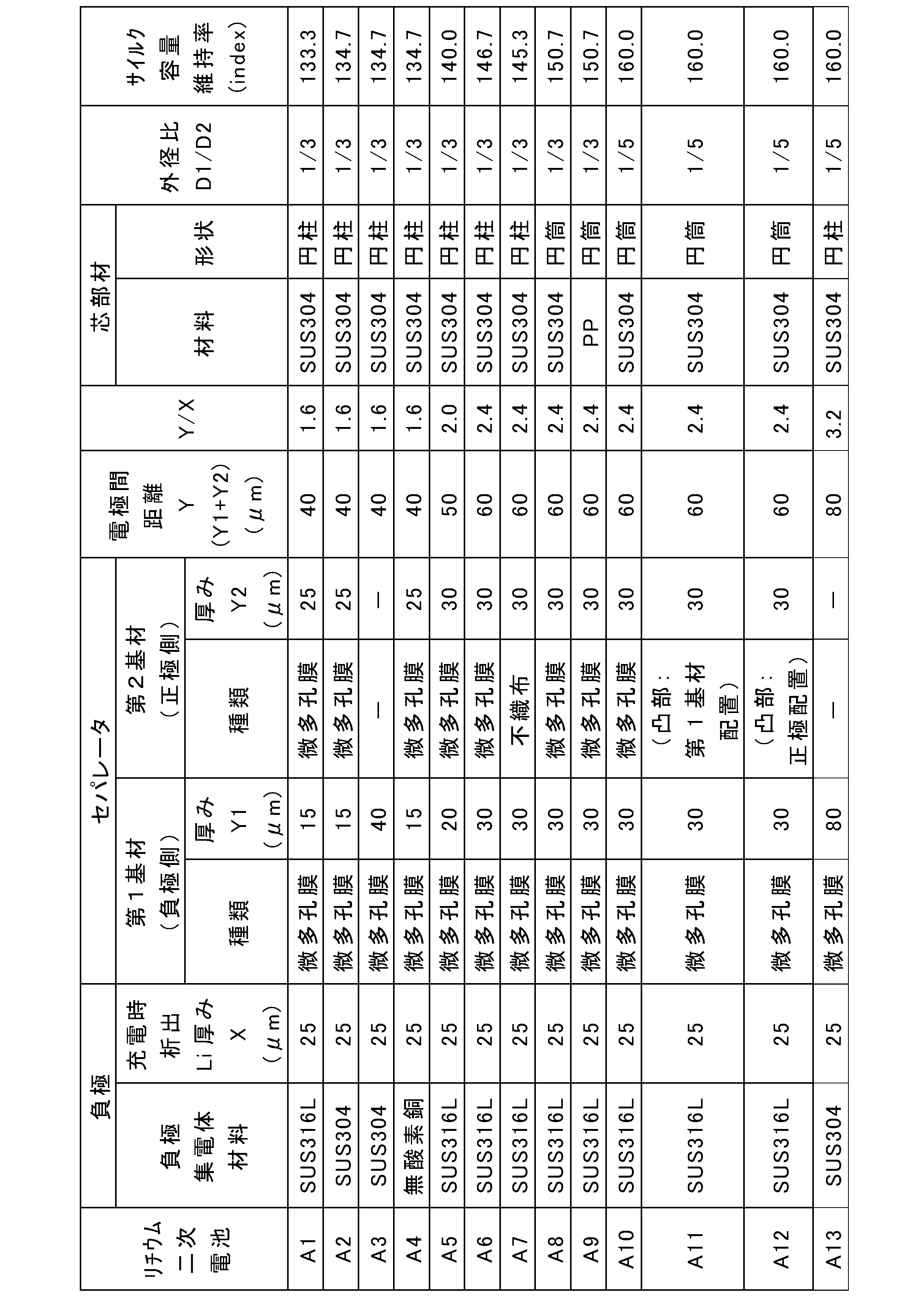
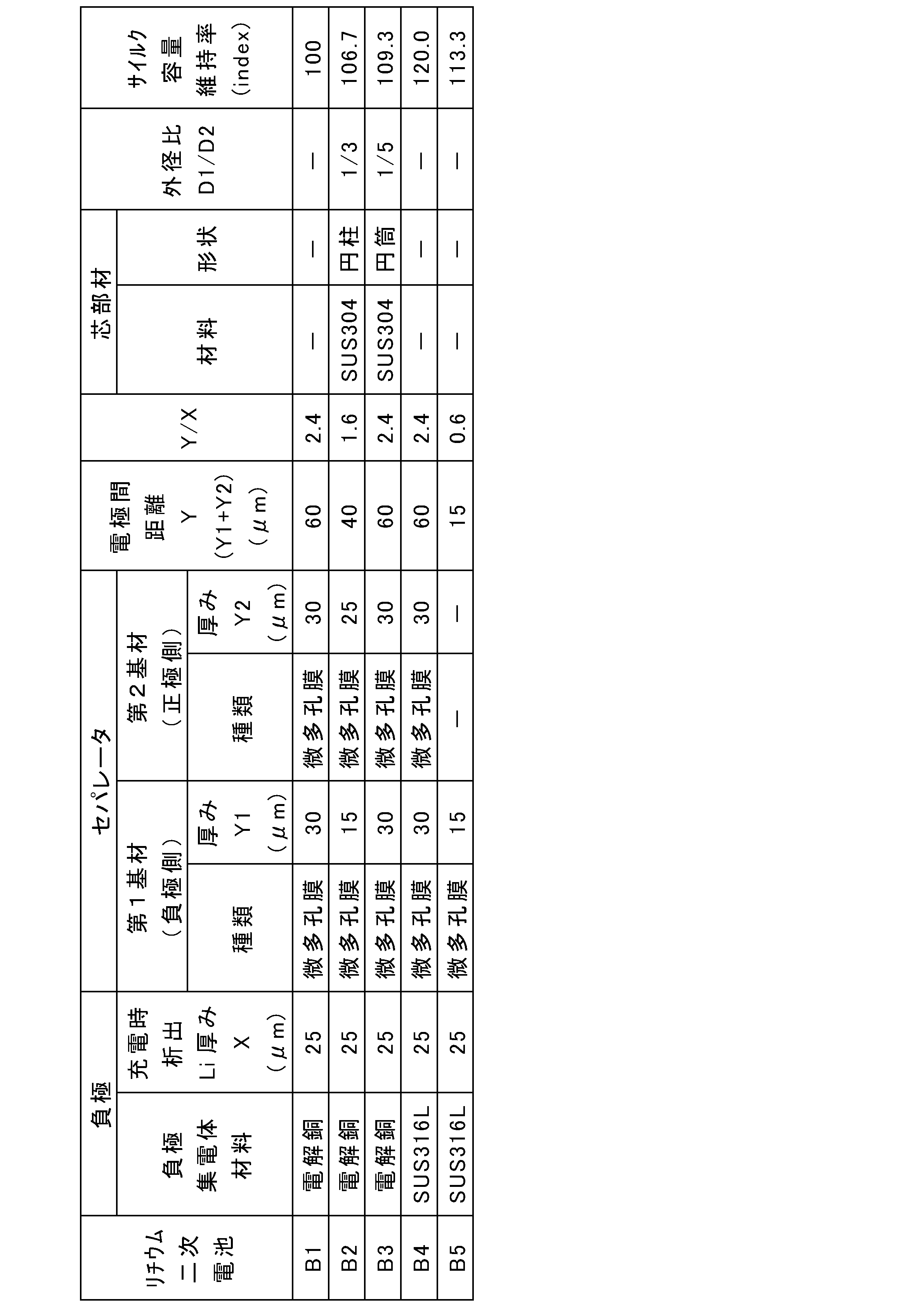
これに対して、負極集電体にSUS316箔を用い、かつ、芯部材付き電極群を用いた電池A10では、電池B1に対して、容量維持率が大幅に60%増大した(B1→A10)。
11 正極
12 負極
13 セパレータ
13A 第1基材
13B 第2基材
13C ライン状凸部
14 電極群
15 電池缶
16 封口体
17、18 絶縁板
19 正極リード
20 負極リード
21 段部
22 フィルタ
23 下弁体
24 絶縁部材
25 上弁体
26 キャップ
27 ガスケット
28 空間
29 芯部材
100、600 正極複合体
200、400 負極複合体
300、500、700 正負極積層体
Claims (10)
- 正極と、負極集電体を備える負極と、前記正極と前記負極との間に配置されたセパレータと、を有する巻回型の電極群と、
前記電極群の中空に配置された芯部材と、
リチウムイオン伝導性を有する非水電解質と、
を具備し、
前記負極では、充電時にリチウム金属が析出し、放電時に前記リチウム金属が溶解し、
前記負極集電体は、オーステナイト系ステンレス鋼箔または無酸素銅箔である、リチウム二次電池。 - 充電時に前記負極に析出するリチウム金属の厚みXと、放電時の前記正極と前記負極との間の距離Yとは、Y/X>1.5の関係を満たす、請求項1に記載のリチウム二次電池。
- 前記セパレータは、微多孔シートおよび不織布シートからなる群より選択される少なくとも1種の基材を含む、請求項1または2に記載のリチウム二次電池。
- 前記セパレータは、複数の前記基材により構成されている、請求項3に記載のリチウム二次電池。
- 前記セパレータは、微多孔シートと、前記微多孔シートの少なくとも一方の表面に配置された耐熱層とを含み、
前記電極群において、前記正極および前記負極の少なくとも一方と、前記微多孔シートとの間に、前記耐熱層が配置されている、請求項1または2に記載のリチウム二次電池。 - 前記セパレータは、基材および凸部の積層体により構成され、
前記凸部により、前記正極および前記負極の少なくとも一方と、前記基材との間に、空間が設けられている、請求項1または2に記載のリチウム二次電池。 - 前記芯部材は、前記電極群の巻き始め側の端部に固定されている、請求項1~6のいずれか1項に記載のリチウム二次電池。
- 前記芯部材の材料が、金属材料または樹脂材料である、請求項1~7のいずれか1項に記載のリチウム二次電池。
- 前記芯部材の形状が、円筒状である、請求項1~8のいずれか1項に記載のリチウム二次電池。
- 前記芯部材の外径D1と、放電時の前記電極群の外径D2とは、D1/D2≦1/4の関係を満たす、請求項1~9のいずれか1項に記載のリチウム二次電池。
Priority Applications (4)
| Application Number | Priority Date | Filing Date | Title |
|---|---|---|---|
| EP23780878.7A EP4503243A4 (en) | 2022-03-31 | 2023-03-30 | Lithium secondary battery |
| US18/851,295 US20250055041A1 (en) | 2022-03-31 | 2023-03-30 | Lithium secondary battery |
| JP2024512797A JPWO2023190870A1 (ja) | 2022-03-31 | 2023-03-30 | |
| CN202380026317.XA CN118872120A (zh) | 2022-03-31 | 2023-03-30 | 锂二次电池 |
Applications Claiming Priority (2)
| Application Number | Priority Date | Filing Date | Title |
|---|---|---|---|
| JP2022-060717 | 2022-03-31 | ||
| JP2022060717 | 2022-03-31 |
Publications (1)
| Publication Number | Publication Date |
|---|---|
| WO2023190870A1 true WO2023190870A1 (ja) | 2023-10-05 |
Family
ID=88202863
Family Applications (1)
| Application Number | Title | Priority Date | Filing Date |
|---|---|---|---|
| PCT/JP2023/013183 Ceased WO2023190870A1 (ja) | 2022-03-31 | 2023-03-30 | リチウム二次電池 |
Country Status (5)
| Country | Link |
|---|---|
| US (1) | US20250055041A1 (ja) |
| EP (1) | EP4503243A4 (ja) |
| JP (1) | JPWO2023190870A1 (ja) |
| CN (1) | CN118872120A (ja) |
| WO (1) | WO2023190870A1 (ja) |
Cited By (4)
| Publication number | Priority date | Publication date | Assignee | Title |
|---|---|---|---|---|
| WO2025047688A1 (ja) * | 2023-08-31 | 2025-03-06 | パナソニックIpマネジメント株式会社 | リチウム二次電池 |
| WO2025070644A1 (ja) * | 2023-09-29 | 2025-04-03 | パナソニックIpマネジメント株式会社 | リチウム二次電池 |
| WO2025249437A1 (ja) * | 2024-05-31 | 2025-12-04 | パナソニックIpマネジメント株式会社 | 二次電池 |
| WO2026018597A1 (ja) * | 2024-07-17 | 2026-01-22 | 大日本印刷株式会社 | 巻芯用部材、巻芯、巻芯付き蓄電要素及び蓄電デバイス |
Citations (9)
| Publication number | Priority date | Publication date | Assignee | Title |
|---|---|---|---|---|
| JP2001229970A (ja) | 2000-02-16 | 2001-08-24 | Shin Kobe Electric Mach Co Ltd | 円筒形リチウムイオン電池 |
| JP2003308873A (ja) * | 2002-04-17 | 2003-10-31 | Sony Corp | 非水電解質二次電池 |
| JP2012201964A (ja) * | 2011-03-28 | 2012-10-22 | Jx Nippon Mining & Metals Corp | 圧延銅箔及びそれを用いた二次電池 |
| JP2017195028A (ja) * | 2016-04-18 | 2017-10-26 | 日立マクセル株式会社 | 非水電解液電池およびその製造方法 |
| JP2019057422A (ja) * | 2017-09-21 | 2019-04-11 | イビデン株式会社 | 蓄電デバイス用電極及び蓄電デバイス |
| JP2019212601A (ja) * | 2018-05-31 | 2019-12-12 | パナソニックIpマネジメント株式会社 | リチウム二次電池 |
| US20200127320A1 (en) * | 2017-09-07 | 2020-04-23 | SZ DJI Technology Co., Ltd. | Lithium metal battery |
| WO2022209601A1 (ja) * | 2021-03-30 | 2022-10-06 | パナソニックIpマネジメント株式会社 | リチウム二次電池 |
| WO2023276756A1 (ja) * | 2021-06-30 | 2023-01-05 | パナソニックIpマネジメント株式会社 | リチウム二次電池 |
Family Cites Families (3)
| Publication number | Priority date | Publication date | Assignee | Title |
|---|---|---|---|---|
| JPH11185819A (ja) * | 1997-12-19 | 1999-07-09 | Sony Corp | 非水電解液二次電池 |
| JP4129965B2 (ja) * | 2003-05-15 | 2008-08-06 | 日立マクセル株式会社 | 非水電解液電池 |
| EP3576185B1 (en) * | 2018-05-31 | 2023-02-01 | Panasonic Intellectual Property Management Co., Ltd. | Lithium secondary battery |
-
2023
- 2023-03-30 EP EP23780878.7A patent/EP4503243A4/en active Pending
- 2023-03-30 JP JP2024512797A patent/JPWO2023190870A1/ja active Pending
- 2023-03-30 CN CN202380026317.XA patent/CN118872120A/zh active Pending
- 2023-03-30 WO PCT/JP2023/013183 patent/WO2023190870A1/ja not_active Ceased
- 2023-03-30 US US18/851,295 patent/US20250055041A1/en active Pending
Patent Citations (9)
| Publication number | Priority date | Publication date | Assignee | Title |
|---|---|---|---|---|
| JP2001229970A (ja) | 2000-02-16 | 2001-08-24 | Shin Kobe Electric Mach Co Ltd | 円筒形リチウムイオン電池 |
| JP2003308873A (ja) * | 2002-04-17 | 2003-10-31 | Sony Corp | 非水電解質二次電池 |
| JP2012201964A (ja) * | 2011-03-28 | 2012-10-22 | Jx Nippon Mining & Metals Corp | 圧延銅箔及びそれを用いた二次電池 |
| JP2017195028A (ja) * | 2016-04-18 | 2017-10-26 | 日立マクセル株式会社 | 非水電解液電池およびその製造方法 |
| US20200127320A1 (en) * | 2017-09-07 | 2020-04-23 | SZ DJI Technology Co., Ltd. | Lithium metal battery |
| JP2019057422A (ja) * | 2017-09-21 | 2019-04-11 | イビデン株式会社 | 蓄電デバイス用電極及び蓄電デバイス |
| JP2019212601A (ja) * | 2018-05-31 | 2019-12-12 | パナソニックIpマネジメント株式会社 | リチウム二次電池 |
| WO2022209601A1 (ja) * | 2021-03-30 | 2022-10-06 | パナソニックIpマネジメント株式会社 | リチウム二次電池 |
| WO2023276756A1 (ja) * | 2021-06-30 | 2023-01-05 | パナソニックIpマネジメント株式会社 | リチウム二次電池 |
Non-Patent Citations (1)
| Title |
|---|
| See also references of EP4503243A4 |
Cited By (5)
| Publication number | Priority date | Publication date | Assignee | Title |
|---|---|---|---|---|
| WO2025047688A1 (ja) * | 2023-08-31 | 2025-03-06 | パナソニックIpマネジメント株式会社 | リチウム二次電池 |
| WO2025070644A1 (ja) * | 2023-09-29 | 2025-04-03 | パナソニックIpマネジメント株式会社 | リチウム二次電池 |
| WO2025249437A1 (ja) * | 2024-05-31 | 2025-12-04 | パナソニックIpマネジメント株式会社 | 二次電池 |
| WO2026018597A1 (ja) * | 2024-07-17 | 2026-01-22 | 大日本印刷株式会社 | 巻芯用部材、巻芯、巻芯付き蓄電要素及び蓄電デバイス |
| JP7827228B1 (ja) * | 2024-07-17 | 2026-03-10 | 大日本印刷株式会社 | 巻芯用部材、巻芯、巻芯付き蓄電要素及び蓄電デバイス |
Also Published As
| Publication number | Publication date |
|---|---|
| CN118872120A (zh) | 2024-10-29 |
| JPWO2023190870A1 (ja) | 2023-10-05 |
| EP4503243A1 (en) | 2025-02-05 |
| EP4503243A4 (en) | 2025-10-29 |
| US20250055041A1 (en) | 2025-02-13 |
Similar Documents
| Publication | Publication Date | Title |
|---|---|---|
| US8178244B2 (en) | Non-aqueous electrolyte battery and battery pack | |
| WO2023190870A1 (ja) | リチウム二次電池 | |
| JP5704413B2 (ja) | 非水電解質二次電池 | |
| WO2022209601A1 (ja) | リチウム二次電池 | |
| JP7113227B2 (ja) | リチウム二次電池 | |
| EP4235872B1 (en) | Winding-type nonaqueous electrolyte secondary battery | |
| JP5585834B2 (ja) | リチウムイオン二次電池 | |
| WO2023190872A1 (ja) | リチウム二次電池 | |
| JP2019160776A (ja) | リチウム二次電池 | |
| JPWO2017007015A1 (ja) | 非水電解質電池及び電池パック | |
| WO2023074846A1 (ja) | リチウム二次電池 | |
| JP6227168B1 (ja) | リチウムイオン電池およびその製造方法 | |
| JP5327523B2 (ja) | 二次電池 | |
| EP4503244A1 (en) | Secondary battery | |
| CN110024197A (zh) | 非水电解质电池及电池包 | |
| US12040486B2 (en) | Electrode, electrode group, battery, and battery pack | |
| JP4318905B2 (ja) | リチウム二次電池 | |
| WO2026070782A1 (ja) | 二次電池 | |
| WO2024143219A1 (ja) | リチウム二次電池 | |
| US20240322217A1 (en) | Lithium secondary battery | |
| JP5165875B2 (ja) | 非水電解質電池 | |
| WO2024143221A1 (ja) | リチウム二次電池 | |
| WO2026029032A1 (ja) | リチウム二次電池 | |
| JP2004214212A (ja) | リチウム二次電池 | |
| JP2016085910A (ja) | 電池 |
Legal Events
| Date | Code | Title | Description |
|---|---|---|---|
| 121 | Ep: the epo has been informed by wipo that ep was designated in this application |
Ref document number: 23780878 Country of ref document: EP Kind code of ref document: A1 |
|
| ENP | Entry into the national phase |
Ref document number: 2024512797 Country of ref document: JP Kind code of ref document: A |
|
| WWE | Wipo information: entry into national phase |
Ref document number: 202380026317.X Country of ref document: CN |
|
| WWE | Wipo information: entry into national phase |
Ref document number: 18851295 Country of ref document: US |
|
| WWE | Wipo information: entry into national phase |
Ref document number: 2023780878 Country of ref document: EP |
|
| ENP | Entry into the national phase |
Ref document number: 2023780878 Country of ref document: EP Effective date: 20241031 |
|
| NENP | Non-entry into the national phase |
Ref country code: DE |