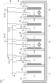
WO2023190771A1 - リチウム同位体濃縮装置、多段式リチウム同位体濃縮装置、およびリチウム同位体濃縮方法 - Google Patents
リチウム同位体濃縮装置、多段式リチウム同位体濃縮装置、およびリチウム同位体濃縮方法 Download PDFInfo
- Publication number
- WO2023190771A1 WO2023190771A1 PCT/JP2023/012998 JP2023012998W WO2023190771A1 WO 2023190771 A1 WO2023190771 A1 WO 2023190771A1 JP 2023012998 W JP2023012998 W JP 2023012998W WO 2023190771 A1 WO2023190771 A1 WO 2023190771A1
- Authority
- WO
- WIPO (PCT)
- Prior art keywords
- electrode
- tank
- lithium
- aqueous solution
- electrolyte membrane
- Prior art date
- Legal status (The legal status is an assumption and is not a legal conclusion. Google has not performed a legal analysis and makes no representation as to the accuracy of the status listed.)
- Ceased
Links
Images


Classifications
-
- B—PERFORMING OPERATIONS; TRANSPORTING
- B01—PHYSICAL OR CHEMICAL PROCESSES OR APPARATUS IN GENERAL
- B01D—SEPARATION
- B01D59/00—Separation of different isotopes of the same chemical element
- B01D59/38—Separation by electrochemical methods
- B01D59/42—Separation by electrochemical methods by electromigration; by electrophoresis
-
- B—PERFORMING OPERATIONS; TRANSPORTING
- B01—PHYSICAL OR CHEMICAL PROCESSES OR APPARATUS IN GENERAL
- B01D—SEPARATION
- B01D59/00—Separation of different isotopes of the same chemical element
- B01D59/38—Separation by electrochemical methods
-
- B—PERFORMING OPERATIONS; TRANSPORTING
- B01—PHYSICAL OR CHEMICAL PROCESSES OR APPARATUS IN GENERAL
- B01D—SEPARATION
- B01D59/00—Separation of different isotopes of the same chemical element
- B01D59/10—Separation by diffusion
- B01D59/12—Separation by diffusion by diffusion through barriers
-
- B—PERFORMING OPERATIONS; TRANSPORTING
- B01—PHYSICAL OR CHEMICAL PROCESSES OR APPARATUS IN GENERAL
- B01D—SEPARATION
- B01D61/00—Processes of separation using semi-permeable membranes, e.g. dialysis, osmosis or ultrafiltration; Apparatus, accessories or auxiliary operations specially adapted therefor
- B01D61/42—Electrodialysis; Electro-osmosis ; Electro-ultrafiltration; Membrane capacitive deionization
- B01D61/44—Ion-selective electrodialysis
- B01D61/46—Apparatus therefor
- B01D61/461—Apparatus therefor comprising only a single cell, only one anion or cation exchange membrane or one pair of anion and cation membranes
-
- B—PERFORMING OPERATIONS; TRANSPORTING
- B01—PHYSICAL OR CHEMICAL PROCESSES OR APPARATUS IN GENERAL
- B01D—SEPARATION
- B01D61/00—Processes of separation using semi-permeable membranes, e.g. dialysis, osmosis or ultrafiltration; Apparatus, accessories or auxiliary operations specially adapted therefor
- B01D61/42—Electrodialysis; Electro-osmosis ; Electro-ultrafiltration; Membrane capacitive deionization
- B01D61/44—Ion-selective electrodialysis
- B01D61/46—Apparatus therefor
- B01D61/464—Apparatus therefor comprising the membrane sequence CC
-
- B—PERFORMING OPERATIONS; TRANSPORTING
- B01—PHYSICAL OR CHEMICAL PROCESSES OR APPARATUS IN GENERAL
- B01D—SEPARATION
- B01D61/00—Processes of separation using semi-permeable membranes, e.g. dialysis, osmosis or ultrafiltration; Apparatus, accessories or auxiliary operations specially adapted therefor
- B01D61/42—Electrodialysis; Electro-osmosis ; Electro-ultrafiltration; Membrane capacitive deionization
- B01D61/44—Ion-selective electrodialysis
- B01D61/46—Apparatus therefor
- B01D61/468—Apparatus therefor comprising more than two electrodes
-
- B—PERFORMING OPERATIONS; TRANSPORTING
- B01—PHYSICAL OR CHEMICAL PROCESSES OR APPARATUS IN GENERAL
- B01D—SEPARATION
- B01D61/00—Processes of separation using semi-permeable membranes, e.g. dialysis, osmosis or ultrafiltration; Apparatus, accessories or auxiliary operations specially adapted therefor
- B01D61/42—Electrodialysis; Electro-osmosis ; Electro-ultrafiltration; Membrane capacitive deionization
- B01D61/44—Ion-selective electrodialysis
- B01D61/52—Accessories; Auxiliary operation
-
- C—CHEMISTRY; METALLURGY
- C02—TREATMENT OF WATER, WASTE WATER, SEWAGE, OR SLUDGE
- C02F—TREATMENT OF WATER, WASTE WATER, SEWAGE, OR SLUDGE
- C02F1/00—Treatment of water, waste water, or sewage
- C02F1/46—Treatment of water, waste water, or sewage by electrochemical methods
- C02F1/469—Treatment of water, waste water, or sewage by electrochemical methods by electrochemical separation, e.g. by electro-osmosis, electrodialysis, electrophoresis
- C02F1/4693—Treatment of water, waste water, or sewage by electrochemical methods by electrochemical separation, e.g. by electro-osmosis, electrodialysis, electrophoresis electrodialysis
-
- C—CHEMISTRY; METALLURGY
- C22—METALLURGY; FERROUS OR NON-FERROUS ALLOYS; TREATMENT OF ALLOYS OR NON-FERROUS METALS
- C22B—PRODUCTION AND REFINING OF METALS; PRETREATMENT OF RAW MATERIALS
- C22B26/00—Obtaining alkali, alkaline earth metals or magnesium
- C22B26/10—Obtaining alkali metals
- C22B26/12—Obtaining lithium
-
- C—CHEMISTRY; METALLURGY
- C22—METALLURGY; FERROUS OR NON-FERROUS ALLOYS; TREATMENT OF ALLOYS OR NON-FERROUS METALS
- C22B—PRODUCTION AND REFINING OF METALS; PRETREATMENT OF RAW MATERIALS
- C22B4/00—Electrothermal treatment of ores or metallurgical products for obtaining metals or alloys
- C22B4/02—Light metals
-
- C—CHEMISTRY; METALLURGY
- C22—METALLURGY; FERROUS OR NON-FERROUS ALLOYS; TREATMENT OF ALLOYS OR NON-FERROUS METALS
- C22B—PRODUCTION AND REFINING OF METALS; PRETREATMENT OF RAW MATERIALS
- C22B4/00—Electrothermal treatment of ores or metallurgical products for obtaining metals or alloys
- C22B4/08—Apparatus
-
- C—CHEMISTRY; METALLURGY
- C25—ELECTROLYTIC OR ELECTROPHORETIC PROCESSES; APPARATUS THEREFOR
- C25B—ELECTROLYTIC OR ELECTROPHORETIC PROCESSES FOR THE PRODUCTION OF COMPOUNDS OR NON-METALS; APPARATUS THEREFOR
- C25B1/00—Electrolytic production of inorganic compounds or non-metals
- C25B1/01—Products
- C25B1/02—Hydrogen or oxygen
- C25B1/04—Hydrogen or oxygen by electrolysis of water
-
- C—CHEMISTRY; METALLURGY
- C25—ELECTROLYTIC OR ELECTROPHORETIC PROCESSES; APPARATUS THEREFOR
- C25B—ELECTROLYTIC OR ELECTROPHORETIC PROCESSES FOR THE PRODUCTION OF COMPOUNDS OR NON-METALS; APPARATUS THEREFOR
- C25B9/00—Cells or assemblies of cells; Constructional parts of cells; Assemblies of constructional parts, e.g. electrode-diaphragm assemblies; Process-related cell features
- C25B9/17—Cells comprising dimensionally-stable non-movable electrodes; Assemblies of constructional parts thereof
- C25B9/19—Cells comprising dimensionally-stable non-movable electrodes; Assemblies of constructional parts thereof with diaphragms
- C25B9/23—Cells comprising dimensionally-stable non-movable electrodes; Assemblies of constructional parts thereof with diaphragms comprising ion-exchange membranes in or on which electrode material is embedded
-
- C—CHEMISTRY; METALLURGY
- C25—ELECTROLYTIC OR ELECTROPHORETIC PROCESSES; APPARATUS THEREFOR
- C25B—ELECTROLYTIC OR ELECTROPHORETIC PROCESSES FOR THE PRODUCTION OF COMPOUNDS OR NON-METALS; APPARATUS THEREFOR
- C25B9/00—Cells or assemblies of cells; Constructional parts of cells; Assemblies of constructional parts, e.g. electrode-diaphragm assemblies; Process-related cell features
- C25B9/60—Constructional parts of cells
- C25B9/67—Heating or cooling means
-
- C—CHEMISTRY; METALLURGY
- C25—ELECTROLYTIC OR ELECTROPHORETIC PROCESSES; APPARATUS THEREFOR
- C25B—ELECTROLYTIC OR ELECTROPHORETIC PROCESSES FOR THE PRODUCTION OF COMPOUNDS OR NON-METALS; APPARATUS THEREFOR
- C25B9/00—Cells or assemblies of cells; Constructional parts of cells; Assemblies of constructional parts, e.g. electrode-diaphragm assemblies; Process-related cell features
- C25B9/70—Assemblies comprising two or more cells
- C25B9/73—Assemblies comprising two or more cells of the filter-press type
- C25B9/77—Assemblies comprising two or more cells of the filter-press type having diaphragms
-
- B—PERFORMING OPERATIONS; TRANSPORTING
- B01—PHYSICAL OR CHEMICAL PROCESSES OR APPARATUS IN GENERAL
- B01D—SEPARATION
- B01D2313/00—Details relating to membrane modules or apparatus
- B01D2313/22—Cooling or heating elements
-
- B—PERFORMING OPERATIONS; TRANSPORTING
- B01—PHYSICAL OR CHEMICAL PROCESSES OR APPARATUS IN GENERAL
- B01D—SEPARATION
- B01D2313/00—Details relating to membrane modules or apparatus
- B01D2313/36—Energy sources
- B01D2313/365—Electrical sources
-
- B—PERFORMING OPERATIONS; TRANSPORTING
- B01—PHYSICAL OR CHEMICAL PROCESSES OR APPARATUS IN GENERAL
- B01D—SEPARATION
- B01D59/00—Separation of different isotopes of the same chemical element
- B01D59/10—Separation by diffusion
- B01D59/12—Separation by diffusion by diffusion through barriers
- B01D59/14—Construction of the barrier
-
- C—CHEMISTRY; METALLURGY
- C02—TREATMENT OF WATER, WASTE WATER, SEWAGE, OR SLUDGE
- C02F—TREATMENT OF WATER, WASTE WATER, SEWAGE, OR SLUDGE
- C02F2101/00—Nature of the contaminant
- C02F2101/10—Inorganic compounds
-
- C—CHEMISTRY; METALLURGY
- C02—TREATMENT OF WATER, WASTE WATER, SEWAGE, OR SLUDGE
- C02F—TREATMENT OF WATER, WASTE WATER, SEWAGE, OR SLUDGE
- C02F2201/00—Apparatus for treatment of water, waste water or sewage
- C02F2201/46—Apparatus for electrochemical processes
- C02F2201/461—Electrolysis apparatus
- C02F2201/46105—Details relating to the electrolytic devices
- C02F2201/46115—Electrolytic cell with membranes or diaphragms
-
- C—CHEMISTRY; METALLURGY
- C25—ELECTROLYTIC OR ELECTROPHORETIC PROCESSES; APPARATUS THEREFOR
- C25B—ELECTROLYTIC OR ELECTROPHORETIC PROCESSES FOR THE PRODUCTION OF COMPOUNDS OR NON-METALS; APPARATUS THEREFOR
- C25B1/00—Electrolytic production of inorganic compounds or non-metals
- C25B1/01—Products
- C25B1/14—Alkali metal compounds
- C25B1/16—Hydroxides
Definitions
- the present invention relates to a lithium isotope concentrator, a multistage lithium isotope concentrator, and a lithium isotope concentrator method for separating lithium isotopes.
- Lithium (Li) has two stable isotopes, 7 Li and 6 Li, whose natural abundance ratios are 92.41 mol% and 7.59 mol%.
- 7 Li which has a mass number of 7
- 6 Li which has a mass number of 6
- 7 Li is used to adjust the pH (hydrogen ion concentration) of the coolant of a nuclear reactor.
- 6 Li is used to produce tritium, the fuel for nuclear fusion reactors. Therefore, technologies have been developed to concentrate and separate 7 Li and 6 Li to a state containing less of the other isotope, and lithium ion Li + can be selectively extracted from seawater, etc. using the amalgam method, molten salt method, distillation method, etc.
- Adsorption methods and electrodialysis methods for example, Patent Document 1
- the lithium isotope concentrator 101 partitions the processing tank 7 into a supply tank 11 and a recovery tank 12 using an electrolyte membrane 2 with electrodes 131 and 132 made of porous membranes attached to both sides, and a power supply between the electrodes 131 and 132. 151 are connected with the electrode 131 as the positive electrode.
- the supply tank 11 is charged with a Li-containing aqueous solution FS such as a lithium hydroxide (LiOH) aqueous solution as a Li source
- the recovery tank 12 is charged with a 6 Li recovery aqueous solution ES such as pure water.
- the amount of movement of 6 Li + per time is larger than that of 7 Li + . This is particularly noticeable in a short period of time immediately after the start of operation (start of voltage application), so a switching element 105s or the like is connected to the power supply 151 and voltage is applied intermittently to alternate between short-term voltage application and stopping. By repeating this, 6 Li can be efficiently concentrated (Patent Document 4, Non-Patent Document 1).
- Patent Document 4 The methods described in Patent Document 4 and the like have room for further improvement in order to increase the isotope separation coefficient.
- the present invention has been made in view of the above problems, and an object thereof is to provide a more efficient lithium isotope concentrator, a multistage lithium isotope concentrator, and a lithium isotope concentrator method using electrodialysis. shall be.
- the lithium isotope concentrator includes a lithium ion conductive electrolyte membrane, a processing tank partitioned into a first tank and a second tank by the lithium ion conductive electrolyte membrane, and the first tank and the second tank.
- a first electrode provided in one of the second tanks;
- a second electrode with a porous structure provided in contact with a surface of the lithium ion conductive electrolyte membrane on the other tank side; in the tank, a third electrode is provided on the second electrode in a spaced relation on the opposite side of the lithium ion conductive electrolyte membrane, and a third electrode is provided on the first electrode and the second electrode with respect to the third electrode.
- a power supply that applies the same voltage with the first tank side set as positive;
- An aqueous solution containing lithium ions with a high isotope ratio of 6 Li is recovered in the second tank.
- the multi-stage lithium isotope concentrator according to the present invention comprises two or more of the lithium isotope concentrators connected together so that the treatment tanks are integrated, and each of the lithium isotope concentrators has a A lithium ion conductive electrolyte membrane is arranged at a distance from each other so as to partition the integrated treatment tank into three or more tanks, and the second tank of one of the two adjacent lithium isotope concentrators is separated from the second tank of the other.
- the first tank also serves as the first tank.
- the first electrode is provided in the first tank, and the third electrode is provided in the second tank. further provided with two or more of the lithium ion conductive electrolyte membranes, partitioning the processing tank into three or more tanks in the order of the first tank, one or more intermediate tanks, and the second tank, The second electrode is provided in contact with the lithium ion conductive electrolyte membrane that partitions the first tank and the intermediate tank adjacent thereto.
- the lithium isotope enrichment method comprises, in a treatment tank partitioned into a first tank and a second tank by a lithium ion conductive electrolyte membrane, converting 6 Li and 7 Li contained in the first tank into lithium
- an aqueous solution containing lithium ions having a higher 6 Li isotope ratio than the aqueous solution is recovered in the second tank from an aqueous solution containing lithium ions in an ionized state.
- the lithium isotope enrichment method according to the present invention includes a first electrode provided in one of the first tank and the second tank, and a surface of the lithium ion conductive electrolyte membrane on the other tank side.
- a second electrode having a porous structure provided in contact with the second electrode; and a third electrode provided spaced apart from the second electrode on the opposite side of the lithium ion conductive electrolyte membrane in the other tank. Apply the same voltage to both.
- an aqueous solution with a higher 6 Li isotope ratio can be recovered safely and with high productivity. Furthermore, according to the multistage lithium isotope concentrator according to the present invention, the isotope ratio of 6 Li can be further increased.
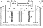
- FIG. 1 is a schematic diagram illustrating the configuration of a lithium isotope concentrator according to a first embodiment of the present invention.
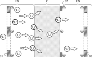
- FIG. 2 is a schematic diagram of the lithium isotope concentrator shown in FIG. 1, illustrating electrodialysis of lithium ions in the lithium isotope concentration method according to the first embodiment of the present invention.
- FIG. 2 is a circuit diagram of the lithium isotope concentrator shown in FIG. 1, illustrating a lithium isotope concentrator method according to a first embodiment of the present invention.
- FIG. 2 is an enlarged view of a main part of the lithium isotope concentrator shown in FIG. 1, illustrating the behavior of lithium ions in an initial state during electrodialysis of lithium ions.
- FIG. 1 is a schematic diagram illustrating the configuration of a lithium isotope concentrator according to a first embodiment of the present invention.
- FIG. 2 is a schematic diagram of the lithium isotope concentrator shown in FIG. 1, illustrating electrodialysis of lithium
- FIG. 2 is an enlarged view of a main part of the lithium isotope concentrator shown in FIG. 1, illustrating the behavior of lithium ions immediately after the start of movement in lithium ion electrodialysis.
- FIG. 2 is an enlarged view of a main part of the lithium isotope concentrator shown in FIG. 1, illustrating the behavior of moving lithium ions in electrodialysis of lithium ions.
- This is a model that explains ionic conduction in electrolytes. It is a graph explaining the applied voltage dependence of the amount of movement per time and isotope ratio in electrodialysis of lithium ions by simulation.
- FIG. 1 is an enlarged view of a main part of the lithium isotope concentrator shown in FIG. 1, illustrating the behavior of lithium ions immediately after the start of movement in lithium ion electrodialysis.
- FIG. 2 is an enlarged view of a main part of the lithium isotope concentrator shown in FIG. 1, illustrating the behavior of moving lithium ions in electrodia
- FIG. 2 is a schematic diagram illustrating the configuration of an isotope concentrator and electrodialysis of lithium ions in a lithium isotope concentration method according to a modification of the first embodiment of the present invention.
- FIG. 2 is a schematic diagram illustrating the configuration of a multistage lithium isotope concentrator as a lithium isotope concentrator according to a modification of the first embodiment of the present invention.
- 1 is a schematic diagram illustrating the configuration of a multistage lithium isotope concentrator according to a first embodiment of the present invention.
- FIG. 2 is a schematic diagram illustrating the configuration of a lithium isotope concentrator according to a second embodiment of the present invention.
- 11 is a schematic diagram of the lithium isotope concentrator shown in FIG.
- FIG. 10 is a schematic diagram illustrating the configuration of a lithium isotope concentrator according to a first modification of the second embodiment of the present invention.
- 13 is a schematic diagram of the lithium isotope concentrator shown in FIG. 12, illustrating electrodialysis of lithium ions in the lithium isotope concentration method. It is a schematic diagram explaining the composition of the lithium isotope concentrator concerning the 2nd modification of the 2nd embodiment of the present invention.
- 15 is a schematic diagram of the lithium isotope concentrator shown in FIG. 14, illustrating electrodialysis of lithium ions in the lithium isotope concentration method.
- FIG. 2 is a schematic diagram illustrating the configuration of a lithium isotope concentrator according to a third embodiment of the present invention. It is a time chart explaining the transition of applied voltage in the lithium isotope enrichment method according to the third embodiment of the present invention.
- FIG. 3 is a schematic diagram illustrating the configuration of a multistage lithium isotope concentrator according to a third embodiment of the present invention.
- FIG. 19 is a schematic diagram illustrating a lithium isotope concentration method using the multistage lithium isotope concentrator shown in FIG. 18.
- FIG. 19 is a schematic diagram illustrating a lithium isotope concentration method using the multistage lithium isotope concentrator shown in FIG. 18.
- FIG. 18 is a schematic diagram illustrating a lithium isotope concentration method using the multistage lithium isotope concentrator shown in FIG. 18.
- FIG. 2 is a schematic diagram illustrating the configuration of a lithium isotope concentrator according to a first modification of the third embodiment of the present invention. It is a time chart explaining the transition of the applied voltage in the lithium isotope enrichment method according to the first modification of the third embodiment of the present invention.
- 21 is a schematic diagram of the lithium isotope concentrator shown in FIG. 20, illustrating a lithium isotope concentrator method according to a first modification of the third embodiment of the present invention.
- FIG. 21 is an enlarged view of a main part of the lithium isotope concentrator shown in FIG. 20, illustrating the behavior of lithium ions after the movement of lithium ions stops in electrodialysis of lithium ions.
- FIG. 7 is a schematic diagram illustrating another configuration of the lithium isotope concentrator according to the first modification of the third embodiment of the present invention. It is a time chart explaining the transition of the applied voltage in the lithium isotope enrichment method according to the second modification of the third embodiment of the present invention.
- FIG. 2 is a schematic diagram illustrating the configuration of a multistage lithium isotope concentrator according to a first modification of the third embodiment of the present invention.
- 27 is a schematic diagram illustrating a lithium isotope concentration method using the multistage lithium isotope concentrator shown in FIG. 26.
- FIG. 27 is a schematic diagram illustrating a lithium isotope concentration method using the multistage lithium isotope concentrator shown in FIG. 26.
- FIG. 2 is a schematic diagram illustrating the configuration of a multistage lithium isotope concentrator according to a second modification of the second embodiment of the present invention.
- FIG. 29 is a schematic diagram illustrating a lithium isotope concentration method using the multistage lithium isotope concentrator shown in FIG. 28.
- FIG. 29 is a schematic diagram illustrating a lithium isotope concentration method using the multistage lithium isotope concentrator shown in FIG. 28.
- FIG. 29 is a schematic diagram illustrating a lithium isotope concentration method using the multistage lithium isotope concentrator shown in FIG. 28. It is a graph showing the amount of movement of lithium ions and the isotope separation coefficient of lithium according to Examples and Comparative Examples.
- 1 is a schematic diagram of a lithium isotope concentrator illustrating a conventional lithium isotope concentrator method using electrodialysis.
- a form (embodiment) for carrying out a lithium isotope concentrator, a multistage lithium isotope concentrator, and a lithium isotope concentrator method according to the present invention will be described with reference to the drawings.
- the sizes of specific elements may be exaggerated or the shapes simplified for clarity of explanation.
- the same elements as in the previous embodiment are denoted by the same reference numerals, and the description thereof will be omitted as appropriate.
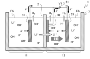
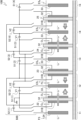
- the lithium isotope concentrator 1 includes a treatment tank 7, an electrolyte membrane (lithium ion conductive electrolyte membrane) 2, a first electrode 31, a second electrode 32, A third electrode 33, a power source 51, and a stirrer (circulation means) 8 are provided.
- the treatment tank 7 is divided into two parts by the electrolyte membrane 2: a supply tank (first tank) 11 that accommodates the Li-containing aqueous solution FS, and a recovery tank (second tank) 12 that accommodates the aqueous solution ES for Li recovery. It's partitioned off.
- the first electrode 31 is provided within the supply tank 11 .
- the second electrode 32 has a porous structure and is provided to cover the surface of the electrolyte membrane 2 on the recovery tank 12 side.
- the third electrode 33 is provided within the recovery tank 12 so as to be spaced apart from the electrolyte membrane 2 and the second electrode 32 .
- the power source 51 has a positive (+) pole connected to the first electrode 31 and the second electrode 32, and a negative (-) pole connected to the third electrode 33.
- the stirrer 8 circulates the Li-containing aqueous solution FS in the supply tank 11 and the 6 Li recovery aqueous solution ES in the recovery tank 12, respectively.
- the treatment tank 7 is made of a material that does not undergo deterioration such as corrosion even when it comes into contact with the Li-containing aqueous solution FS and the 6 Li recovery aqueous solution ES.
- the processing tank 7 only needs to have a volume corresponding to the required processing capacity, and its shape etc. are not particularly limited.
- the electrolyte membrane 2 is an electrolyte having lithium ion conductivity, and preferably does not conduct electrons e.sup.- . Furthermore, when the Li-containing aqueous solution FS contains metal ions other than Li + , it is preferable that the electrolyte membrane 2 does not conduct these metal ions. More preferred is an electrolyte made of ceramics having these properties. Specifically, lithium lanthanum titanium oxide (La 2/3-x Li 3x TiO 3 , also referred to as LLTO) may be used. Such an electrolyte membrane 2 has lattice defects at a constant rate, and since the size of the lattice defect sites is small, metal ions having a diameter larger than Li + do not conduct.
- LLTO lithium lanthanum titanium oxide
- a site such as the A site where Li can exist will be referred to as a Li site, and a Li site having a vacancy will be referred to as a Li site defect.
- the first electrode 31 and the second electrode 32 are provided in order to maintain the same potential between both surfaces of the electrolyte membrane 2 when Li + is moved within the electrolyte membrane 2 .
- the third electrode 33 is paired with the first electrode 31 to apply a positive voltage to the Li-containing aqueous solution FS with respect to the 6 Li recovery aqueous solution ES, and to apply a positive voltage to the 6 Li recovery aqueous solution ES.
- This is an electrode for forming a lower potential than the front surface (hereinafter referred to as the back surface as appropriate).
- the first electrode 31 is provided within the supply tank 11 .
- the second electrode 32 is provided in contact with the surface (back surface) of the electrolyte membrane 2 on the recovery tank 12 side.
- the third electrode 33 is arranged in the recovery tank 12 so as not to contact the electrolyte membrane 2 and the second electrode 32.
- the first electrode 31 is provided in the supply tank 11, and as shown in FIG.
- the Li-containing aqueous solution FS can come into contact with the entire surface of the electrolyte membrane 2.
- the first electrode 31 has a mesh shape through which the aqueous solution passes so that the contact area with the Li-containing aqueous solution FS is increased and the Li-containing aqueous solution FS in contact with the surface of the electrolyte membrane 2 in the supply tank 11 is continuously replaced. It is preferable that the shape is as follows.
- the first electrode 31 is preferably formed of an electrode material that has electron conductivity and is stable even when a voltage is applied in the Li-containing aqueous solution FS, and further has a catalytic activity for the reaction of the following formula (1).
- the first electrode 31 is preferably made of platinum (Pt), for example.
- the first electrode 31 may be made of carbon (C), and it is more preferable that fine particles of Pt, which function as a catalyst, be supported on the surface of the first electrode 31 .
- the second electrode 32 is provided in contact with the back surface of the electrolyte membrane 2, and applies a voltage to a wide range of the electrolyte membrane 2, while the aqueous solution ES for 6 Li recovery is in contact with a sufficient area of the back surface of the electrolyte membrane 2. It has a porous structure such as a network.
- the second electrode 32 is formed of an electrode material that has electronic conductivity and is stable when a voltage is applied even in the aqueous 6 Li recovery solution ES, which contains Li + as the reaction progresses, and is further formed using the following formula ( Materials having catalytic activity for the reaction of 1) and the reaction of the following formula (4) are preferred. It is further preferable that the second electrode 32 is made of a material that can be easily processed into the shape described above.
- the second electrode 32 is preferably made of, for example, platinum (Pt) as such an electrode material.
- Pt platinum
- Li + contained in the electrolyte membrane 2 is expressed as Li + (electrolyte).
- the following formula (4) shows a reaction in which Li + in the electrolyte membrane 2 moves to an aqueous solution ( 6 Li recovery aqueous solution ES).
- the third electrode 33 is disposed in the recovery tank 12 so as not to contact the electrolyte membrane 2 and the second electrode 32, and is disposed parallel to the second electrode 32. Furthermore, as described later, the third electrode 33 makes the electric field E1 (see FIG. 2) generated in the 6 Li recovery aqueous solution ES stronger with respect to the voltage V1 applied between it and the second electrode 32. Therefore, it is preferable to arrange the electrode 32 as close to the second electrode 32 as possible to prevent short-circuiting. In addition, the third electrode 33 increases the contact area with the 6 Li recovery aqueous solution ES, and replaces the 6 Li recovery aqueous solution ES that contacts the back surface of the electrolyte membrane 2 (second electrode 32) in the recovery tank 12.
- the third electrode 33 has electronic conductivity and is formed of an electrode material that is stable when a voltage is applied in the aqueous 6 Li recovery solution ES, and furthermore, Materials with catalytic activity are preferred.
- the third electrode 33 can be made of carbon (C), copper (Cu), or stainless steel, which is stable at a potential lower than the potential at which the reaction of formula (2) below occurs, and the surface of these materials can be used as a catalyst. It is more preferable that functional Pt fine particles be supported.
- the first electrode 31 may be provided in contact with the surface of the electrolyte membrane 2 (see first electrode 31B in a modification of the third embodiment shown in FIG. 20).
- the first electrode 31 is designed to apply voltage to a wide range of the electrolyte membrane 2 and to contact a sufficient area of the surface of the electrolyte membrane 2 with the Li-containing aqueous solution FS in the same manner as the second electrode 32. , has a porous structure such as a network.
- the first electrode 31 is preferably made of a material that has catalytic activity for the reaction of the following formula (3) in addition to the reaction of the formula (1) above, and is also preferably a material that can be easily processed into the shape described above. Note that the following formula (3) shows a reaction in which Li + in the aqueous solution (Li-containing aqueous solution FS) moves into the electrolyte membrane 2.
- the power supply 51 is a DC power supply, and applies a voltage having the same polarity and magnitude to the third electrode 33 to the first electrode 31 and the second electrode 32, with the supply tank 11 side being positive.
- the power supply 51 has a positive electrode connected to the first electrode 31 and the second electrode 32, a negative electrode connected to the third electrode 33, and a negative electrode connected to the first electrode 31 and the second electrode 32.
- a positive voltage V1 (voltage +V1) is applied to the second electrode 32 with respect to the third electrode 33.
- the stirrer 8 circulates the Li-containing aqueous solution FS in the supply tank 11 so that the Li-containing aqueous solution FS in contact with the surfaces of the first electrode 31 and the electrolyte membrane 2 is continuously replaced, and also circulates the Li-containing aqueous solution FS in the supply tank 11.
- This device circulates the 6 Li recovery aqueous solution ES in the recovery tank 12 so that the 6 Li recovery aqueous solution ES in contact with the back surface of the electrolyte membrane 2 and the third electrode 33 is continuously replaced.
- the stirrer 8 may be provided as necessary to circulate only one of the Li-containing aqueous solution FS and the aqueous solution for recovering 6 Li ES.
- a known device can be applied to the stirrer 8, and for example, as shown in FIG. 1, a screw immersed in the aqueous solution FS, ES is rotated by a motor.
- each of the tanks 11 and 12 may be provided with an inlet and an outlet and connected to a circulation tank installed outside the processing tank 7, and the aqueous solutions FS and ES may be circulated using a pump, respectively.
- the Li-containing aqueous solution FS is a Li source that supplies Li, and is an aqueous solution containing 7 Li and 6 Li cations 7 Li + and 6 Li + , for example, a lithium hydroxide (LiOH) aqueous solution, with at least lithium isotopes.
- 7 Li + and 6 Li + are contained in the natural abundance ratio.
- the Li-containing aqueous solution FS preferably has a higher Li + concentration, and more preferably is a saturated aqueous solution or a supersaturated aqueous solution of Li + when the lithium isotope concentrator 1 starts operating.
- the aqueous solution ES for 6 Li recovery is an aqueous solution for accommodating lithium ion Li + recovered from the Li-containing aqueous solution FS, especially Li + whose 6 Li isotope ratio is at least higher than that of the Li-containing aqueous solution FS, and the lithium isotope
- the water is, for example, pure water.
- 7 Li and 6 Li 7 Li + and 6 Li +
- Li (Li + ) when not distinguished from each other.
- the lithium isotope concentrator 1 may further include a cooling device that cools the electrolyte membrane 2 via the Li-containing aqueous solution FS or the 6 Li recovery aqueous solution ES in order to bring the electrolyte membrane 2 to a predetermined temperature.
- the cooling device may be a known device for cooling liquid, and preferably has a temperature adjustment function.
- the cooling device is, for example, an immersion type, in which a pipe through which a refrigerant flows (refrigerant pipe) is immersed in the aqueous solution ES for recovering 6 Li in the recovery tank 12.
- the cooling device only needs to be able to bring the electrolyte membrane 2 to a predetermined temperature, and it is not necessary to keep the Li-containing aqueous solution FS and the 6 Li recovery aqueous solution ES at a uniform temperature.
- a stirring device may be provided.
- the refrigerant pipes of the cooling device are made of a material that does not undergo deterioration such as corrosion even if it comes into contact with the Li-containing aqueous solution FS or the aqueous solution for 6 Li recovery ES, and its shape is not particularly defined.
- the refrigerant pipes are installed so as to meander in a plane according to the dimensions of the plate-shaped electrolyte membrane 2, and to face each other in the vicinity over a wide area of the electrolyte membrane 2. Ru.
- the refrigerant pipe may be introduced into both the supply tank 11 and the recovery tank 12.
- the cooling device may have a structure in which the processing tank 7 has a double structure (jacket tank) and the refrigerant is circulated inside the tank (jacket part).
- a configuration may be adopted in which the Li-containing aqueous solution FS or the 6 Li recovery aqueous solution ES is circulated outside the treatment tank 7 by a pump and cooled by a heat exchanger.
- the temperature of the electrolyte membrane 2 will be described later, but to ensure that the temperature is below 30°C and that the aqueous solutions FS and ES do not freeze, for example, the aqueous solution ES for 6 Li recovery is used to start operation of the lithium isotope concentrator 1 (start of electrodialysis). ) If the water is pure water, the temperature shall be 0°C or higher. The temperature of the electrolyte membrane 2 can be measured by using the liquid temperature of the Li-containing aqueous solution FS or the 6 Li recovery aqueous solution ES as an alternative.
- the lithium isotope concentrator 1 may further include a liquid level sensor or the like in order to sense changes in the amounts of the Li-containing aqueous solution FS and the 6 Li recovery aqueous solution ES during operation.
- a liquid level sensor or the like in order to sense changes in the amounts of the Li-containing aqueous solution FS and the 6 Li recovery aqueous solution ES during operation.
- the lithium isotope concentrator 1 It is preferable that the Li-containing aqueous solution FS and the 6 Li recovery aqueous solution ES are configured so as not to be exposed to the atmosphere.
- the lithium isotope concentrator 1 must be equipped with an exhaust means to exhaust H 2 and O 2 generated during operation (due to the reactions of formulas (1) and (2)) so as not to fill the inside. is preferable for safety.
- Lithium isotope enrichment method In the lithium isotope concentration method according to the present invention, in a treatment tank 7 partitioned into a supply tank 11 and a recovery tank 12 by an electrolyte membrane 2, a 6 Li recovery aqueous solution ES is collected from a Li-containing aqueous solution FS stored in the supply tank 11. This is a method of recovering in a recovery tank 12.
- a first electrode 31 provided in the supply tank 11 and a second electrode 32 provided on the back surface of the electrolyte membrane 2 are connected to the recovery tank 12.
- a positive voltage V1 is applied to a third electrode 33 that is provided spaced apart from the electrolyte membrane 2 and the second electrode 32.
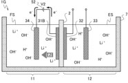
- the power supply 51 applies a positive voltage V1 (voltage +V1) to the first electrode 31 and the second electrode 32, which are shorted to each other, with respect to the third electrode 33. Apply. Then, the following reaction occurs in the supply tank 11. In the vicinity of the first electrode 31, hydroxide ions (OH - ) in the Li-containing aqueous solution FS cause the reaction of formula (1) below, releasing electrons e - to the first electrode 31, and water (H 2 O) and oxygen (O 2 ) are generated, and OH - is reduced.
- V1 voltage +V1
- Li + tries to cause the reaction of formula (3) below in which Li + dissolves in the electrolyte membrane 2. It moves to the vicinity of the surface of the electrolyte membrane 2.
- a concentration gradient occurs in which the concentration of Li + is higher in the vicinity of the surface of the electrolyte membrane 2 than in the vicinity of the back surface of the electrolyte membrane 2 in the 6 Li recovery aqueous solution ES.
- Li near the back surface of the electrolyte membrane 2 is + moves to the vicinity of the third electrode 33 along the electric field +E1 generated between the second electrode 32, that is, the back surface of the electrolyte membrane 2, and the third electrode 33.
- the Li + concentration remains low near the back surface of the electrolyte membrane 2, and the chemical potential difference of Li + with respect to the surface layer of the electrolyte membrane 2 and the vicinity of the surface is maintained.
- the charge compensation for the entire Li-containing aqueous solution FS and the 6 Li recovery aqueous solution ES is the reaction amount of the reaction of formula (2) (generation of H 2 ) in the vicinity of the third electrode 33. and the reaction amount of the reaction (O 2 generation) of equation (1) in the vicinity of each of the electrodes 31 and 32.
- the amount of O 2 generated in the Li-containing aqueous solution FS (the reaction amount of the reaction of equation (1) in the vicinity of the first electrode 31) is the amount of Li + that has moved through the electrolyte membrane 2 (the reaction of equation (3) and the reaction amount of equation (1)). 4) corresponds to each reaction amount of the reaction.
- the amount of Li + that has moved through the electrolyte membrane 2 (the amount of Li + movement) is less than the amount of H 2 generated in the vicinity of the third electrode 33 ( 6 Li recovery aqueous solution ES), and is This corresponds to the difference between the amount of O 2 generated in the vicinity of the two electrodes 32.
- the voltage V1 is set to be equal to or higher than the voltage at which the electrolysis reaction of water occurs, and set to be equal to or higher than +1.229 V (25° C.) when the Li-containing aqueous solution FS and the aqueous solution for recovering 6 Li ES have the same pH (hydrogen ion concentration).
- the voltage V1 needs to be set to a value several hundred mV larger than the theoretical voltage of 1.229V, depending on the electrode performance that determines the electrode reaction overvoltage of each of the electrodes 31, 32, and 33. Note that the higher the pH of the Li-containing aqueous solution FS is with respect to the 6 Li recovery aqueous solution ES, the lower the voltage at which the water electrolysis reaction occurs.
- the lithium isotope concentrator 1 includes a closed circuit in which a power source 51 and a 6 Li recovery aqueous solution ESE are connected in a ring. Currents I1 and I2 flow counterclockwise.
- the lithium isotope concentrator 1 further includes a closed circuit that branches off from the positive electrode of the power source 51 and connects the Li-containing aqueous solution FSE and the electrolyte membrane 2 in series in this order, and supplies current from the current I1 as indicated by the gray broken arrow.
- the resistance of the electrolyte membrane 2 (Li + transfer resistance) is R EL
- the resistance of the Li-containing aqueous solution FS E resistance between the first electrode 31 and the electrolyte membrane 2) is R FS
- the resistance of the 6 Li recovery aqueous solution ES E is ( The resistance between the second electrode 32 and the third electrode 33) is expressed as R ES .
- the lithium isotope concentrator 1 further has a reaction resistance R Ox1 due to the reaction of formula (1) (O 2 generation) at the first electrode 31 and a reaction resistance R Ox1 due to the reaction of formula (1) (O 2 generation) at the second electrode 32.
- R Ox2 includes the reaction resistance R Red due to the reaction (H 2 generation) of equation (2) at the third electrode 33.
- the circuit constituting the lithium isotope concentrator 1 is expressed by the following formula (5).
- Li + moves in the opposite direction (in the same direction as the current I3) instead of the electron e - .
- OH - and, in the opposite direction Li + and H + move instead of part of the electrons e - .
- V1-(R ES +R Red )I1 R Ox2
- I2 (R Ox1 +R FS +R EL )I3...(5)
- the amount of Li + flowing per hour (Li + mobility) in the electrolyte membrane 2 is large, that is, the current I3 is large.
- the resistance R EL of the electrolyte membrane 2 is low.
- the resistance R EL of the electrolyte membrane 2 depends on the Li + concentration of the aqueous solution FS, ES that the electrolyte membrane 2 is in contact with and the defect concentration of the Li site that is in equilibrium with the Li + concentration between both sides of the electrolyte membrane 2. The higher the slope, the lower the slope.
- the resistances R FS , R ES , R Ox1 , and R Red are designed to be low. Therefore, it is preferable that the first electrode 31 and the third electrode 33 have a large area immersed in the aqueous solutions FS and ES so that the reaction resistances R Ox1 and R Red are low. It is preferable to use a material that has high catalytic activity for the reaction 2). Further, as described above, it is preferable that the distance between the second electrode 32 and the third electrode 33 be short enough to prevent short-circuiting, thereby strengthening the electric field E1 and lowering the resistance R ES .
- the distance between the first electrode 31 and the electrolyte membrane 2 be shortened to reduce the resistance R FS .
- the first electrode 31 may have a porous structure and be in contact with the surface of the electrolyte membrane 2, and the resistance R FS can be minimized (0), but the contact area with the Li-containing aqueous solution FS is reduced. Therefore, the reaction resistance R Ox1 increases. Furthermore, since the contact area of the surface of the electrolyte membrane 2 with the Li-containing aqueous solution FS is reduced, the resistance R EL increases. Therefore, it is preferable to arrange the first electrode 31 close to each other so as not to prevent the surface of the electrolyte membrane 2 from coming into contact with the Li-containing aqueous solution FS.
- FIGS. 4A to 4C are enlarged cross-sectional views of the vicinity of the electrolyte membrane 2 of the lithium isotope concentrator 1, and the second electrode 32 is partially in contact with the back surface of the electrolyte membrane 2.
- the aqueous solutions FS and ES only the 7 Li + and 6 Li + contained therein are indicated by ⁇ , respectively.
- Li + ( 7 Li + , 6 Li + ) in the Li-containing aqueous solution FS tries to dissolve in the electrolyte membrane 2 as a reaction of the following formula (3).
- Li + adsorbed near the Li site defect on the surface of the electrolyte membrane 2 sneaks into the Li site defect.
- Li + in the electrolyte membrane 2 attempts to move to the 6 Li recovery aqueous solution ES, and Li + at the Li site on the back surface moves to the 6 Li recovery aqueous solution ES.
- V1 between the second electrode 32 and the third electrode 33, as shown in FIG. 2 and is attracted to the third electrode 33 by electrostatic attraction.
- Li + that has penetrated into the Li site defects on the surface of the electrolyte membrane 2 from the Li-containing aqueous solution FS jumps to the Li site defects near the deep side (back side), and then further from there to the Li site defects near the back side. Jump to defects.
- Li + repeatedly moves from the Li site defect of the electrolyte membrane 2 to the nearby Li site defect, and finally, as shown in FIG. 4C, as the reaction of the above formula (4), Move from the Li site to the aqueous solution ES for 6 Li recovery.
- Li + at the Li adsorption site on the back surface is increased by the application of the voltage V1 between the second electrode 32 and the third electrode 33. is detached from the back surface due to electrostatic repulsion, and the vacancy of the Li site defect on the back surface is promoted.
- the Li + that had penetrated into the Li site defects on the surface or was adsorbed near them moved to the deep part of the electrolyte membrane 2, and as a result, the Li + sites were further absorbed into the vacant Li site defects.
- Li + adsorbed nearby moves and sneaks in, or new Li + is adsorbed from the Li-containing aqueous solution FS, and these Li + similarly move in the electrolyte membrane 2. Furthermore, as Li + moves through the electrolyte membrane 2, Li site defects are filled with Li + and become vacant again. The Li + that was on the surface can now start moving to the back side.
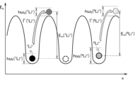
- FIG. 5 is a model explaining ion conduction in an electrolyte, where x indicates a position in the thickness direction of the electrolyte membrane 2, and E p indicates potential energy.
- Li + 7 Li + , 6 Li +
- x indicates a position in the thickness direction of the electrolyte membrane 2
- E p indicates potential energy.
- Li + ( 7 Li + , 6 Li + ) stably exists at the Li site where the potential energy is minimal, but if the nearby Li site is a vacancy (represented by a broken line ⁇ ).
- E a E D /2+E m , E D : defect generation energy).
- the ions are thermally vibrating at the frequency ⁇ 0 at the position of the minimum potential energy, and can hop at a frequency (hopping rate ⁇ ) corresponding to this frequency (frequency factor) ⁇ 0 .
- the frequency ⁇ 0 is inversely proportional to the square root of the ion's mass. Since the mass of 6 Li is 6/7 times smaller than that of 7 Li, the frequency ⁇ 0 is ( ⁇ (7/6)) times that of 7 Li. Movement speed becomes ( ⁇ (7/6)) times faster than 7 Li. Furthermore, for example, if 7 Li + and 6 Li + exist at two equidistant locations in the vicinity of a certain Li site defect in electrolyte membrane 2, it is assumed that 6 Li + will preferentially jump to the defect. be done.
- the zero point vibration h ⁇ I depends on the isotope and is larger for 6 Li + than for 7 Li + .
- the zero point vibration h ⁇ S is larger in 6 Li + . Therefore, 6 Li + , which has a smaller mass than 7 Li + , has higher potential energy in both the ground state and the excited state, taking into account the zero-point vibrations h ⁇ I and h ⁇ S .
- FIG. 6 shows the application of the amount of 6 Li + and 7 Li + transferred per time and the isotope ratio of transferred Li + by simulation when the received energy is the voltage applied between both surfaces of the electrolyte membrane 2. Shows voltage dependence. In the simulation, the distribution of activation energy E a according to the Maxwell-Boltzmann distribution was approximated by a normal distribution.
- the mobilities of 6 Li + and 7 Li + increase from 0 in an S-curve shape as the applied voltage increases, but for 7 Li + , the activation energy E a 6 Li + with a small value shifts to the small voltage side and is also higher by the frequency ⁇ 0 ratio.
- lim ⁇ in FIG. 6 represents the limit of the amount of 6 Li + movement per time. Therefore, the smaller the applied voltage, that is, the received energy, in the range of moving 6 Li + in the electrolyte membrane 2, the more 6 Li + moves relative to 7 Li + . Then, as the energy increases and the mobilities of 6 Li + and 7 Li + converge, the difference between them becomes smaller, and the isotope ratio becomes ( ⁇ (7/6))/(1+ ⁇ (7/6) ).
- the ion mobility ⁇ has a relationship with the ion diffusion coefficient D as shown in the following equation (6) (T: temperature (K), k: Boltzmann constant).
- the diffusion coefficient D is proportional to the hopping rate ⁇ , as expressed by the following equation (7) (a: average distance between sites (jump length), n c : carrier density, f: distance between the ion and its surroundings).
- the correlation effect coefficient is determined by d: the dimension of the diffusion field).
- the frequency factor ⁇ 0 in equation (7) is proportional to the temperature T, as expressed by the following equation (8), and (Z s vib /Z I vib ) is inversely proportional to the square root of the mass number m.
- the frequency factor ⁇ 0 is inversely proportional to the square root of the mass number m (h: Planck's constant, Z s vib : phonon distribution function at the saddle point, Z I vib : phonon distribution function in the initial state, C 1 : constant ).
- the diffusion coefficient D is expressed by the following equation (9).
- the ion mobility ⁇ is expressed by the following equation (10) (C 2 : constant). As shown in equation ( 10), the ion mobility ⁇ is higher for 6 Li +, which has a smaller mass number m and activation energy E a , than for 7 Li + .
- the Li + concentration near the back surface of the electrolyte membrane 2 is reduced by the electric field +E1 generated by the applied voltage +V1 between the second electrode 32 and the third electrode 33, and the Li + concentration near the surface is reduced.
- Li + is transferred to the electrolyte membrane 2 only by the chemical potential difference. move it inside. Therefore, compared to the conventional lithium isotope enrichment method shown in FIG.
- the Li-containing aqueous solution FS preferably has a higher Li + concentration, and is more preferably a saturated or supersaturated aqueous Li + solution.
- the Li + concentration of the Li-containing aqueous solution FS decreases.
- the Li-containing aqueous solution FS in the supply tank 11 it is preferable to replace the Li-containing aqueous solution FS in the supply tank 11 every time a predetermined operation application time elapses or when the Li + concentration of the Li-containing aqueous solution FS decreases and falls below a predetermined value. It is preferable to constantly circulate the Li-containing aqueous solution FS to and from the processing tank 7 during operation. Furthermore, by exchanging the Li-containing aqueous solution FS in this way, the 6 Li isotope ratio ( 6 Li / ( 7 Li + 6 Li)) of Li + remaining in the Li-containing aqueous solution FS decreases due to the movement of Li + .
- the electric field +E1 between the second electrode 32 and the third electrode 33 causes Li + to be unevenly distributed near the third electrode 33 to lower the Li + concentration near the back surface of the electrolyte membrane 2. can be maintained.
- the Li + concentration in the entire 6 Li recovery aqueous solution ES does not exceed the Li-containing aqueous solution FS.
- the liquid volume of the aqueous solution ES for 6 Li recovery also decreases due to the reaction of formula (1) and the reaction of formula (2), water (H 2 O) etc. may be added to the recovery tank 12 as necessary. It is preferable. In the lithium isotope concentrator 1, it is preferable that the liquid levels in the supply tank 11 and the recovery tank 12 are the same during operation.
- the ion mobility ⁇ also depends on the temperature T, and the degree of this dependence is influenced by the activation energy E a .
- the mobilities of 7 Li + and 6 Li + increase exponentially as the temperature increases, but 7 Li + , which has a larger activation energy E a , has greater temperature dependence.
- the ratio of 7 Li + with low mobility to 6 Li + with high mobility becomes smaller. Therefore, the 6 Li isotope ratio of moving Li + is higher at lower temperatures where the mobility of Li + is lower.
- the applicable temperature range in this embodiment is above the freezing point and below the boiling point of the aqueous solutions FS and ES, and is 0 to 100° C.
- the temperature of the electrolyte membrane 2 is preferably 20°C or lower, more preferably 15°C or lower, even more preferably 10°C or lower, and even more preferably 5°C or lower.
- the aqueous solution FS, ES, especially the aqueous solution ES for 6 Li recovery may contain a solute that does not permeate the electrolyte membrane 2 so that the freezing point falls below 0°C.
- the aqueous solutions FS and ES containing such solutes should not corrode the electrolyte membrane 2, electrodes 31, 32, 33, etc.
- salts such as sodium chloride (NaCl, common salt), magnesium chloride (MgCl 2 ), calcium chloride (CaCl 2 ), potassium chloride (KCl), etc., which are used as antifreeze agents, or ethylene glycol, etc. Examples include organic solvents.
- the electrolyte membrane 2 can be cooled to below 0°C, more preferably below 0°C, and the 6 Li isotope ratio can be further increased for efficient concentration.
- an aqueous solution containing Li ( 6 Li recovery aqueous solution ES) with a high 6 Li isotope ratio is used in the recovery tank 12 compared to the Li-containing aqueous solution FS in the supply tank 11.
- the 6 Li recovery aqueous solution ES after Li recovery is poured into the empty supply tank 11, while the recovery tank 12 is Replace with pure water and operate as a new 6 Li recovery aqueous solution ES.
- an aqueous solution containing Li with a higher 6 Li isotope ratio is obtained in the recovery tank 12.
- the 6 Li recovery aqueous solution ES can be treated with carbon dioxide gas (CO 2 )
- 6 Li can be recovered by generating lithium carbonate (Li 2 CO 3 ) by bubbling or the like and causing it to precipitate.
- 6 Li can also be recovered by cooling the 6 Li recovery aqueous solution ES after completion of 6 Li concentration to a supersaturated state by cooling or evaporating water , etc. to produce lithium hydroxide (LiOH) and precipitating it. .
- a salt other than sodium chloride such as magnesium chloride
- the moisture should be evaporated before bubbling carbon dioxide gas to prevent precipitation due to the decrease in moisture. It is preferable to remove the salt by a common method such as filtration before bubbling.
- normal electrodialysis or the like for example, see Patent Document 3 may be performed at a temperature of 0° C. or higher, for example, room temperature or higher, and Li can be selectively recovered in pure water or the like. good.
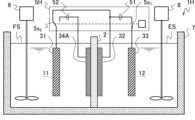
- a lithium isotope concentrator 1A according to a modification of the first embodiment of the present invention includes a treatment tank 7, an electrolyte membrane (lithium ion conductive electrolyte membrane) 2, a first electrode 31A, It includes a second electrode 32A, a third electrode 33A, and a power source 51.
- the treatment tank 7 is divided into two parts by the electrolyte membrane 2: a supply tank (first tank) 11 that accommodates the Li-containing aqueous solution FS, and a recovery tank (second tank) 12 that accommodates the aqueous solution ES for Li recovery. It's partitioned off.
- the first electrode 31A is provided inside the recovery tank 12.
- the second electrode 32A has a porous structure and is provided to cover the surface of the electrolyte membrane 2 on the supply tank 11 side.
- the third electrode 33A is provided within the supply tank 11, spaced apart from the electrolyte membrane 2 and the second electrode 32A.
- the power source 51 has a positive (+) pole connected to the third electrode 33A, and a negative (-) pole connected to the first electrode 31A and the second electrode 32A.
- the lithium isotope concentrator 1A In the lithium isotope concentrator 1A, the arrangement of the first electrode 31A, the second electrode 32A, and the third electrode 33A is replaced with respect to the lithium isotope concentrator 1 according to the first embodiment (see FIG. 1).
- the configuration is as follows.
- the lithium isotope concentrator 1A has the same configuration as the lithium isotope concentrator 1 according to the first embodiment, and includes a stirrer (circulation means) 8, a cooling device, and a liquid level sensor as necessary. , exhaust means, etc. may be provided.
- the first electrode 31A and the second electrode 32A are provided to maintain the same potential between both surfaces of the electrolyte membrane 2, similarly to the first electrode 31 and the second electrode 32 of the first embodiment.
- the third electrode 33A is paired with the first electrode 31A to apply a positive voltage to the Li-containing aqueous solution FS with respect to the 6 Li recovery aqueous solution ES. This is an electrode for applying voltage.
- the first electrode 31A is provided in the recovery tank 12.
- the second electrode 32A is provided in contact with the surface (surface) of the electrolyte membrane 2 on the supply tank 11 side, and the third electrode 33A is provided in the supply tank 11 between the electrolyte membrane 2 and the second electrode 32A. placed so that they do not touch each other.
- the first electrode 31A is provided in the recovery tank 12, and can be placed apart from the back surface of the electrolyte membrane 2, as shown in FIG. 7 as an example. Therefore, the first electrode 31A can have the same configuration as the third electrode 33 of the first embodiment, and is preferably made of a material that has catalytic activity for the reaction of formula (2) below. Alternatively, the first electrode 31A may be provided in contact with the back surface of the electrolyte membrane 2. The second electrode 32A is provided in contact with the surface of the electrolyte membrane 2.
- the second electrode 32A has a porous structure such as a network like the second electrode 32 of the first embodiment, while the second electrode 32A has a porous structure in the Li-containing aqueous solution FS like the first electrode 31 of the first embodiment. It is preferable to use an electrode material that is stable even when an electric current is applied, and further has a catalytic activity for the reaction of the following formula (2) and the reaction of the following formula (3).
- the third electrode 33A is preferably arranged in the supply tank 11 so as not to contact the electrolyte membrane 2 and the second electrode 32A, and is arranged parallel to the second electrode 32A.
- the third electrode 33A is preferably formed of an electrode material that is stable even when a voltage is applied in the Li-containing aqueous solution FS, and furthermore, a material that has catalytic activity for the reaction of the following formula (1) is preferable. . Therefore, the third electrode 33A can have the same configuration as the first electrode 31 of the first embodiment.
- the power supply 51 applies a negative voltage V1 to the first electrode 31A and the second electrode 32A with respect to the third electrode 33A.
- the power source 51 has a positive electrode connected to the third electrode 33A, and a negative electrode connected to the first electrode 31A and the second electrode 32A.
- the lithium isotope concentration method includes a first electrode 31A provided in the recovery tank 12 and a second electrode 32A provided on the surface of the electrolyte membrane 2.
- a negative voltage V1 is applied to the third electrode 33A provided in the supply tank 11 apart from the electrolyte membrane 2 and the second electrode 32A.
- a positive voltage V1 (voltage +V1) is applied to the third electrode 33A with respect to the first electrode 31A and the second electrode 32A.
- the power supply 51 applies a positive voltage V1 (voltage +V1) to the third electrode 33A with respect to the first electrode 31A and the second electrode 32A, which are shorted to each other. Apply. Then, in the supply tank 11, an electric field E1 (electric field +E1) is generated in the Li-containing aqueous solution FS from the third electrode 33A toward the second electrode 32A, as shown by the thick gray arrow, and the following reaction occurs. arise.
- OH - in the Li-containing aqueous solution FS causes the reaction of the following formula (1), releases electrons e - to the first electrode 31, and generates H 2 O and O 2 , OH - decreases.
- H 2 O of the Li-containing aqueous solution FS is supplied with electrons e - , thereby causing the reaction of the following formula (2) to generate H 2 and OH - .
- Li + in the Li-containing aqueous solution FS moves to the second electrode 32A, that is, near the surface of the electrolyte membrane 2 along the electric field +E1.
- the following reaction occurs in the vicinity of the first electrode 31A.
- electrons e - are supplied to H 2 O of the 6 Li recovery aqueous solution ES, so that the reaction of formula (2) below occurs to generate H 2 and OH - .
- the Li + in the electrolyte membrane 2 is increased to 6
- the reaction of the following formula (4) that moves to the Li recovery aqueous solution ES occurs near the back surface of the electrolyte membrane 2.
- the charge compensation for the entire Li-containing aqueous solution FS and the 6 Li recovery aqueous solution ES is the reaction amount of the reaction (O 2 generation) of formula (1) in the vicinity of the third electrode 33A. and the reaction amount of the reaction (H 2 generation) of equation (2) in the vicinity of each of the electrodes 31A and 32A.
- the amount of H 2 generated in the Li recovery aqueous solution ES (the reaction amount of the reaction of equation (2) in the vicinity of the first electrode 31A) is the amount of Li + that has moved through the electrolyte membrane 2 (the amount of reaction of equation (3) and This corresponds to each reaction amount of the reaction of formula (4).
- the amount of Li + that has moved through the electrolyte membrane 2 (the amount of Li + movement) is less than or equal to the amount of O 2 generated in the vicinity of the third electrode 33A (Li-containing aqueous solution FS), and the amount of O 2 generated and This corresponds to the difference from the amount of H 2 generated in the vicinity of 32A.
- the voltage V1 is set to be equal to or higher than the voltage at which the electrolysis reaction of water occurs, as in the first embodiment. In this way, even if the positions of the first electrode 31A, the second electrode 32A, and the third electrode 33A are exchanged, by applying a voltage with the supply tank 11 side being positive, Li in the Li-containing aqueous solution FS can be maintained. + moves through the electrolyte membrane 2 and reaches the 6 Li recovery aqueous solution ES. At this time, since Li + moves in the electrolyte membrane 2 only due to the chemical potential difference, a high 6 Li concentration effect can be obtained as in the first embodiment.
- the lithium isotope enrichment method according to the first embodiment since an electric field +E1 is generated in the aqueous solution ES for 6 Li recovery, Li + is kept away from the electrolyte membrane 2, and both sides of the electrolyte membrane 2 are It is possible to increase the chemical potential difference between Moreover, since the structure can be such that no electrode (first electrode 31) is provided on the surface (surface) of the electrolyte membrane 2 on the side of the supply tank 11, the Li-containing aqueous solution FS does not come into contact with the entire surface of the electrolyte membrane 2. , and a large amount of Li + can be adsorbed. Therefore, the first embodiment allows higher Li + mobility.
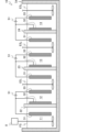
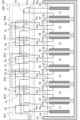
- the recovery tank 12 is separated into two or more tanks by one or more electrolyte membranes 2 between the second electrode 32 and the third electrode 33. It can also be partitioned into a cascade structure. That is, as shown in FIG. 8, a lithium isotope concentrator (multi-stage lithium isotope concentrator) 1B according to another modification of the first embodiment of the present invention has a treatment tank 7A and a treatment tank 7A connected in one direction.
- electrolyte membranes (lithium ion conductive electrolyte membranes) 22, 23, 24, 25, and tank 11 are arranged in parallel at intervals so as to partition into five tanks 11, 12, 13, 14, and 15 in order.
- the lithium isotope concentrator 1B further includes a third electrode 33 in each of the tanks 12, 13, and 14, and a stirrer ( circulation means) 8.
- the recovery tank 12 of the lithium isotope concentrator 1 is divided into three electrolyte membranes 23, 24, 25 between the second electrode 32 and the third electrode 33. It has a partitioned structure into four tanks 12, 13, 14, and 15. That is, the electrolyte membrane 22 that partitions the tank 11 and the tank 12 corresponds to the electrolyte membrane 2 of the lithium isotope concentrator 1 according to the embodiment.
- the electrolyte membranes 22, 23, 24, 25 can each have the same configuration as the electrolyte membrane 2 of the lithium isotope concentrator 1 according to the embodiment, and the electrolyte membranes 22, 23, 24, 25 are not particularly identified. In this case, it will be referred to as an electrolyte membrane 2 as appropriate.
- the supply tank 11 at the left end stores the Li-containing aqueous solution FS similarly to the embodiment described above.
- the tanks 12, 13, 14, and 15 other than the supply tank 11 respectively accommodate 6 Li recovery aqueous solutions ES 1 , ES 2 , ES 3 , and ES 4 .
- 6 Li recovery aqueous solutions ES 1 , ES 2 , ES 3 , ES 4 are used to accommodate lithium ions Li + recovered from the Li-containing aqueous solution FS, similar to the 6 Li recovery aqueous solution ES of the lithium isotope concentrator 1.
- the lithium isotope concentrator 1B starts operating, it is, for example, pure water.
- a tank 15 at the opposite end to the supply tank 11 serves as a recovery tank.
- the processing tank 7A may have any shape as long as it has a volume corresponding to the required processing capacity, and other than that, it can have the same configuration as the processing tank 7 of the lithium isotope concentrator 1 according to the embodiment.
- the resistance between the second electrode 32 and the third electrode 33 arranged in the recovery tank 15, that is, the electrolyte membranes 23, 24, 25, 6 Li recovery aqueous solution ES 1 It is preferable that the sum of the respective resistances of the portions of ES 2 , ES 3 , and 6 Li recovery aqueous solution ES 4 sandwiched between the electrolyte membrane 25 and the third electrode 33 is low.
- the distance between the electrolyte membranes 22 and 23 is short to the extent that the third electrode 33 disposed in the tank 12 does not short-circuit with the second electrode 32. More preferably, it does not come into contact with the electrolyte membrane 23 either.
- the distance between the electrolyte membranes 23, 24, 25 is short enough to avoid contact with the third electrode 33 disposed in each of the tanks 13, 14. Therefore, it is preferable that the tanks 12, 13, and 14 be short in the partitioning direction of the processing tank 7A (the left-right direction in FIG. 8).
- the power source 51A has a positive electrode connected to the first electrode 31 and the second electrode 32, and a negative electrode connected to the third electrode 33, like the power source 51 of the embodiment.
- a third electrode 33 is provided in each of the tanks 12, 13, 14, and 15, and one of them is connected to the negative electrode of a power source 51A.
- the lithium isotope concentrator 1B further includes a switching element 5s3 that connects the negative electrode of the power source 51A to any one of the third electrodes 33. Therefore, since the resistance between the second electrode 32 and the third electrode 33 changes depending on the third electrode 33 to be connected, the power source 51A is preferably a variable power source that changes the applied voltage in stages.
- the stirrer 8 circulates the aqueous solutions FS, ES 1 , ES 2 , ES 3 and ES 4 in the tanks 11, 12, 13, 14 and 15, respectively.
- the lithium isotope concentrator 1B may further include a cooling device (not shown) that cools the electrolyte membranes 22, 23, 24, and 25, if necessary.
- the cooling device has a structure in which, for example, the processing tank 7A has a double structure (jacket tank) and the refrigerant flows therein.
- the other elements are as described in the configuration of the lithium isotope concentrator 1.
- the lithium isotope concentration method using the lithium isotope concentrator 1B according to this modification is the same as the method using the lithium isotope concentrator 1, and the lithium isotope concentration method using the lithium isotope concentrator 1B is the same as the method using the lithium isotope concentrator 1.
- the aqueous solution FS is introduced, and pure water is introduced into the other tanks 12, 13, 14, and 15, respectively.
- the Li + mobility in the electrolyte membrane 2 increases as the Li + concentration of the aqueous solution on the upstream side (supply side) increases.
- Li + is transferred from the Li-containing aqueous solution FS in the supply tank 11 to the aqueous solution ES 1 which is pure water in the tank 12, that is, Li + is transferred only in the electrolyte membrane 22 and the aqueous solution ES is In terms of energy efficiency, it is preferable to increase the Li + concentration of 1 .
- the power supply 51A connects its negative electrode to the third electrode 33 in the tank 12 and applies the voltage V1. Then, when the aqueous solution ES 1 reaches a predetermined Li + concentration, the connection destination of the negative electrode of the power source 51A is switched to the third electrode 33 in the tank 13.
- Li + continues to move from the Li-containing aqueous solution FS to the aqueous solution ES 1 in the tank 12, and from the aqueous solution ES 1 to the tank 12.
- Li + begins to move to the aqueous solution ES 2 in 13.
- the negative electrode of the power supply 51A is connected to the By switching to the third electrode 33 in the tank 14 and further increasing the voltage of the power supply 51A, Li + transfer from the aqueous solution ES 2 to the aqueous solution ES 3 in the tank 14 is started.
- Li + moves from left to right in the figure.
- aqueous solutions ES 1 , ES 2 , ES 3 , and ES 4 in each of tanks 12, 13, 14, and 15 are changed from pure water at the start of operation to LiOH containing different concentrations of Li with different 6 Li isotope ratios. becomes an aqueous solution.
- 6 Li isotope ratio increases in the order of FS ⁇ ES 1 ⁇ ES 2 ⁇ ES 3 ⁇ ES 4 . Therefore, even if the isotope separation coefficient due to the movement of Li + in one electrolyte membrane 2 is not large, Li with a high 6 Li isotope ratio can be recovered from the recovery tank 15.
- the number of electrolyte membranes 2 is not particularly limited, and the larger the number, the more Li with a high 6 Li isotope ratio can be recovered from the tank at the end of the recovery side.
- all the adjacent electrolyte membranes 2, 2 are arranged facing each other, but for example, the adjacent electrolyte membranes 2, 2 may be connected by bending 90 degrees at one or two places. They may also be arranged perpendicular to each other.
- the third electrode 33 is arranged in parallel to the electrolyte membrane 2 on the supply side in the tank of the bent part partitioned by the electrolyte membranes 2, 2 arranged perpendicularly to each other.
- the supply tank 11 is also It is preferable to replace the Li-containing aqueous solution FS or to circulate it to the outside of the treatment tank 7A. Also, during operation, add water (H 2 O), etc. to tanks 12, 13, 14, and 15 as necessary to keep the liquid levels in tanks 11, 12, 13, 14, and 15 even. It is preferable to do so.
- the Li-containing aqueous solution FS and the aqueous solutions ES 1 , ES 2 , ES 3 , ES 4 for recovering 6 Li contain a solute that lowers the freezing point to below 0°C, and the electrolyte membranes 22 , 23 , 24 , 25 are cooled in a cooling device. may be cooled below 0° C. and above the freezing point.
- the lithium isotope concentrator 1 (see FIG. 1) according to the first embodiment supplies the 6 Li recovery aqueous solution ES obtained in the recovery tank 12 after Li recovery to the empty supply tank 11.
- the recovery tank 12 of the lithium isotope concentrator 1 and the supply tank 11 of another lithium isotope concentrator 1 are connected through a flow path such as a pipe, and this supply tank 11 is connected to the recovery tank 12 for 6 Li recovery.
- a multi-stage lithium isotope concentrator that concentrates 6 Li in stages can be provided.
- the aqueous solution ES for 6 Li recovery in the recovery tank 12 may be pumped out using a pump, for example, or the lithium isotope concentrator 1 on the upstream side (supply side) may be installed at a relatively high position and the pipe inclined. It may also be distributed as a structure.
- the aqueous solution may be transferred between the lithium isotope concentrators 1, 1 all the time at a predetermined flow rate, or may be transferred at regular intervals.
- a miniaturized multi-stage lithium isotope concentration can be achieved. It can be a device.
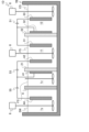
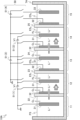
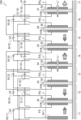
- a multi-stage lithium isotope concentrator according to a first embodiment of the present invention will be described with reference to FIG. 9.
- the multistage lithium isotope concentrator 10 includes a treatment tank 7A, which is partitioned in one direction into four tanks 11, 12, 13, and 14 arranged in parallel at intervals. Three electrolyte membranes (lithium ion conductive electrolyte membranes) 22, 23, 24 are arranged, and a first electrode 31 is arranged facing the surface (left side in the figure) of the electrolyte membranes 22, 23, 24. , a second electrode 32 covering the back surfaces of the electrolyte membranes 22, 23, and 24, a third electrode 33 disposed facing the second electrode 32, and three power supplies 51.
- the multistage lithium isotope concentrator 10 further includes a stirrer (circulation means) 8 in each of the tanks 11, 12, 13, and 14.
- the multistage lithium isotope concentrator 10 has a structure in which three lithium isotope concentrators 1 are connected so that each treatment tank 7 is integrated into a treatment tank 7A, and two adjacent lithium isotope concentrators
- the recovery tank 12 of one of the concentrators 1, 1 serves as the supply tank 11 of the other. Therefore, in the multi-stage lithium isotope concentrator 10, the third electrode 33 and the first electrode 31 are arranged in each of the tanks 12 and 13 except for the tanks 11 and 14 at both ends.
- the electrolyte membranes 22, 23, and 24 are not specifically identified, they are appropriately called the electrolyte membrane 2.
- the tank 11 at the end of the supply tank 11 side (the left side in FIG. 9; hereinafter referred to as the supply side) of the lithium isotope concentrator 1 is the supply tank 11 similarly to the lithium isotope concentrator 1, and contains Li.
- the tanks 12, 13, and 14 respectively contain 6 Li recovery aqueous solutions ES 1 , ES 2 , and ES 3 .
- 6 Li recovery aqueous solutions ES 1 , ES 2 , ES 3 are aqueous solutions for accommodating lithium ions Li + recovered from the Li-containing aqueous solution FS, similar to the 6 Li recovery aqueous solution ES of the lithium isotope concentrator 1.
- the multi-stage lithium isotope concentrator 10 when the multi-stage lithium isotope concentrator 10 starts operating, it is pure water.
- the side of the recovery tank 12 of the lithium isotope concentrator 1 (the right side in FIG. 9) is referred to as the recovery side.
- the tank 14 at the end on the recovery side serves as a recovery tank.
- a second electrode 32, a third electrode 33, and a first electrode 31 are arranged in each of the tanks 12 and 13, excluding the tanks 11 and 14 at both ends, in order from the supply side. be done.
- the third electrode 33 and the first electrode 31 in the tanks 12 and 13 are arranged with a sufficient distance from each other, so that the tanks 12 and 13 are arranged in the partitioning direction (the connecting direction, the left-right direction in FIG. 9) of the processing tank 7A. ) to be long enough.
- the resistance between the third electrode 33 and the first electrode 31 (the resistance of the portion sandwiched between the third electrode 33 and the first electrode 31 of the aqueous solutions ES 1 and ES 2 for 6 Li recovery)
- R ES ′ is than the resistance R ES between the second electrode 32 and the third electrode 33 and the resistance (R FS +R EL ) between the first electrode 31 and the second electrode 32 that sandwich the electrolyte membranes 23 and 24, respectively (see FIG. 3). It is designed to be higher, preferably by a larger difference.
- the first electrode 31 may have a porous structure and be provided in contact with the surfaces of each of the electrolyte membranes 22, 23, and 24.
- the power source 51 is as described in the configuration of the lithium isotope concentrator 1. Further, it is preferable that the three power supplies 51 of the multi-stage lithium isotope concentrator 10 be configured so that they can be independently connected to (drive) the electrodes 31, 32, and 33, respectively. It is preferable that the power supply 51 is not grounded, or that only one unit in the multistage lithium isotope concentrator 10 is grounded. In FIG. The positive terminal of the first power supply 51 is grounded. However, if the resistance R ES ' between the third electrode 33 and the first electrode 31 in each of the tanks 12 and 13 is sufficiently high, each of the two or more power supplies 51 may be grounded.
- the stirrer 8 circulates the aqueous solutions FS, ES 1 , ES 2 and ES 3 in the tanks 11, 12, 13 and 14, respectively.
- the multistage lithium isotope concentrator 10 may further include a cooling device (not shown) that cools the electrolyte membranes 22, 23, and 24, if necessary.
- the other elements are as explained in the configuration of the lithium isotope concentrators 1 and 1B.
- the lithium isotope concentration method using the multistage lithium isotope concentrator 10 is the same as the method using the lithium isotope concentrators 1 and 1B, and in the figure, 7 Li and 6 Li are supplied to the supply tank 11 at the left end in their natural abundance ratio.
- the Li-containing aqueous solution FS contained in the tank is charged, and pure water is charged into each of the other tanks 12, 13, and 14.
- the lithium isotope concentration method using the lithium isotope concentrator 1B see FIG.
- the Li-containing aqueous solution FS in the supply tank 11 is converted into the aqueous solution ES 1 which is pure water in the tank 12.
- only the first power supply 51 on the supply side is driven.
- the second power supply 51 on the supply side is further driven to start moving Li + from the aqueous solution ES 1 to the aqueous solution ES 2 in the tank 13 .
- the third power supply on the supply side is 51 to start transferring Li + from the aqueous solution ES 2 to the aqueous solution ES 3 in the tank 14 .
- the multi-stage lithium isotope concentrator 10 is configured so that an electric field is not substantially generated between the third electrode 33 and the first electrode 31 of the tanks 12 and 13, or even if an electric field is generated between the third electrode 33 and the first electrode 31 of the tanks 12 and 13,
- the electric field +E1 generated between the second electrode 32 and the third electrode 33 is designed to be sufficiently weaker than the electric field +E1 (see FIG. 2).
- the distance between the third electrode 33 and the first electrode 31 is arranged sufficiently wide. With such a configuration, two or more adjacent power supplies 51 can be driven simultaneously.
- the supply of It is preferable to replace the Li-containing aqueous solution FS in the tank 11 or to circulate it to the outside of the processing tank 7A. Also, during operation, it is preferable to add water (H 2 O) or the like to the tanks 12, 13, and 14 as necessary so that the liquid levels in the tanks 11, 12, 13, and 14 are even. .
- the number of electrolyte membranes 2 and electrodes 31, 32, 33 provided for each electrolyte membrane 2 is not particularly defined, and the larger the number, that is, the larger the number of lithium isotope concentrators 1.
- the more 6 Li is connected the more Li with a higher 6 Li isotope ratio can be recovered from the tank at the end of the recovery side.
- the lithium isotope concentrator 1 is connected in one direction, and all adjacent electrolyte membranes 2, 2 are arranged facing each other, but for example, at one or two locations, the lithium isotope concentrator 1 is connected at an angle of 90 degrees.
- Adjacent electrolyte membranes 2, 2 may be arranged perpendicularly to each other by being bent and connected. Since the third electrode 33 and the first electrode 31 are also arranged perpendicularly to each other in the tank of the bent part partitioned by the electrolyte membranes 2, 2 arranged perpendicularly to each other, the interval at the shortest part inside the bend is It is preferable to arrange it so that it has a sufficient length.
- lithium isotope concentrator 1A (see FIG. 7) according to the modification of the first embodiment, two or more units are connected so that the respective processing tanks 7 are integrated, and the multistage lithium isotope concentrator It can be done. Furthermore, one or more lithium isotope concentrators 1 and one or more lithium isotope concentrators 1A can be connected to form a multistage lithium isotope concentrator.
- the Li + concentration of the Li-containing aqueous solution FS is maintained high during operation. Therefore, in addition to replacing the Li-containing aqueous solution FS in the supply tank 11 or circulating it to the outside of the processing tank 7, the Li + concentration of the Li-containing aqueous solution FS can be maintained with good workability and without significantly expanding the equipment. In order to do so, the following configuration was adopted. A lithium isotope concentrator according to a second embodiment of the present invention will be described below.
- the lithium isotope concentrator 1C includes a treatment tank 7B, an electrolyte membrane (lithium ion conductive electrolyte membrane for lithium replenishment) 21, an electrolyte membrane (lithium ion conductive electrolyte membrane) electrolyte membrane) 22, first electrode 31, second electrode 32, third electrode 33, fourth electrode 41, fifth electrode 42, power supply 51, power supply (lithium replenishment power supply) 53, and stirrer (circulation means) 8 Equipped with.
- the processing tank 7B includes a replenishment tank (lithium replenishment tank) 1z containing the Li-containing aqueous solution FS′, a supply tank (first tank) 11 containing the Li-containing aqueous solution FS, and an aqueous solution for Li recovery using the electrolyte membranes 21 and 22. It is partitioned into three collection tanks (second tank) 12 for accommodating ES.
- the lithium isotope concentrator 1C differs from the lithium isotope concentrator 1 according to the first embodiment (see FIG.
- This configuration includes electrodes 41 and 42 provided in each of the replenishment tank 1z and the supply tank 11, which are separated from the supply tank 11, and a power source 53 connected between the electrodes 41 and 42.
- the other configurations are the same as the lithium isotope concentrator 1 according to the first embodiment, and may include a cooling device, a liquid level sensor, an exhaust means, etc., as necessary.
- the portion of the lithium isotope concentrator 1C that is composed of the replenishment tank 1z, the supply tank 11, the electrolyte membrane 21 that partitions these, the electrodes 41, 42, and the power source 53 is a lithium isotope concentrator 1C.
- This is a lithium recovery device using a lithium recovery method using an electrolyte membrane having ion conductivity (for example, Patent Documents 2 and 3).
- This lithium recovery device moves lithium ions from the Li-containing aqueous solution FS' stored in the replenishment tank 1z to the Li-containing aqueous solution FS stored in the supply tank 11. That is, the lithium isotope concentrator 1C according to the present embodiment connects the lithium recovery device and the lithium isotope concentrator 1 according to the first embodiment by integrating their respective processing tanks with the supply tank 11. It is a device with a cascade structure.
- the electrolyte membrane 22 has the same configuration as the electrolyte membrane 2 of the lithium isotope concentrator 1 according to the embodiment.
- the electrolyte membrane 21 can also have the same configuration as the electrolyte membrane 22.
- the fourth electrode 41 and the fifth electrode 42 are electrodes for applying a voltage between both surfaces of the electrolyte membrane 21 as a pair, and the fourth electrode 41 is placed in the replenishment tank 1z, and the fifth electrode 42 is placed in the supply tank. 11 in contact with or facing the electrolyte membrane 21, respectively. It is preferable that one or both of the fourth electrode 41 and the fifth electrode 42 have a porous structure and are in contact with the electrolyte membrane 21, and it is more preferable that one of them is in contact with the electrolyte membrane 21. It is more preferable that the fourth electrode 41 is in contact with the electrolyte membrane 21 as shown in 10 (see Patent Document 3).
- the electrolyte membrane 21 Since at least one of the electrodes 41 and 42 is in contact with the electrolyte membrane 21, a voltage can be applied to a wide range of the electrolyte membrane 21. Since one of the electrodes 41 and 42 is in contact with the electrolyte membrane 21 and the other is separated, even if the voltage V3 applied by the power supply 53 connected between the electrodes 41 and 42 is large to some extent, the electrolyte membrane 21 The potential difference between both surfaces is suppressed, and as will be described later, it is possible to suppress a decrease in the energy efficiency of Li movement in the electrolyte membrane 21.
- the fourth electrode 41 is provided in contact with the surface (surface) of the electrolyte membrane 21 on the replenishment tank 1z side, and applies voltage to a wide range of the electrolyte membrane 21 while applying voltage to the surface of the electrolyte membrane 21.
- the second electrode 32 has a porous structure such as a network so that the Li-containing aqueous solution FS' comes into contact with a sufficient area.
- the fourth electrode 41 is formed of an electrode material that has electron conductivity and is stable even when a voltage is applied in the Li-containing aqueous solution FS', and is a catalyst for the reaction of the following formula (1) and the reaction of the following formula (3).
- a material having activity is preferable, and a material that can be easily processed into the shape described above is preferable.
- the fourth electrode 41 is preferably made of platinum (Pt), for example.
- the fifth electrode 42 is disposed in the supply tank 11 so as not to come into contact with the electrolyte membrane 21 , while preferably not having a long distance from the electrolyte membrane 21 , and preferably disposed parallel to the electrolyte membrane 21 . is preferred.
- the fifth electrode 42 increases the contact area with the Li-containing aqueous solution FS, and so that the Li-containing aqueous solution FS in contact with the surface of the electrolyte membrane 2 in the supply tank 11 is continuously replaced.
- it has a shape such as a mesh through which the aqueous solution passes.
- the fifth electrode 42 is formed of an electrode material that has electronic conductivity and is stable even when a voltage is applied in the Li-containing aqueous solution FS.
- platinum (Pt) is preferable as such an electrode material.
- the fifth electrode 42 may be made of carbon (C), copper (Cu), or stainless steel, which is stable at a potential lower than the potential at which the reaction of formula (2) below occurs, and may be made of carbon (C), copper (Cu), or stainless steel as a catalyst. It is more preferable to carry functional Pt fine particles.
- the fifth electrode 42 may have a porous structure and be provided in contact with the electrolyte membrane 21.
- the fifth electrode 42 and the first electrode 31 are arranged in one supply tank 11.
- the supply tank 11 is designed to have a sufficient length in the partition direction (between the electrolyte membranes 21 and 22) so that the fifth electrode 42 and the first electrode 31 are arranged with a sufficient distance from each other.
- the first electrode 31 and the fifth electrode 42 are connected to the power source 51 and the power source 53, respectively, so that an electric field is not substantially generated between the fifth electrode 42 and the first electrode 31, Or, even if it occurs, it is designed to be sufficiently weak to the extent that it does not inhibit the reactions in the vicinity of the fifth electrode 42 and the first electrode 31.
- the power source 53 is a DC power source like the power source 51, and has a positive electrode connected to the fourth electrode 41, a negative electrode connected to the fifth electrode 42, and a positive electrode to the fourth electrode 41 and a positive electrode to the fifth electrode 42. Apply voltage V3 (voltage +V3). Further, the power source 53 may be a variable power source so that the Li + mobility in the electrolyte membrane 21 can be adjusted.
- the Li-containing aqueous solution FS' is a Li source that supplies Li to the Li-containing aqueous solution FS in order to maintain its Li + concentration high during operation of the lithium isotope concentrator 1C.
- the Li-containing aqueous solution FS' is an aqueous solution containing 7 Li and 6 Li cations 7 Li + and 6 Li + in their natural abundance ratios, and like the Li-containing aqueous solution FS, it is, for example, a lithium hydroxide (LiOH) aqueous solution. .
- the Li-containing aqueous solution FS' be higher at the start of operation of the lithium isotope concentrator 1C ; More preferably, it is a saturated aqueous solution or a supersaturated aqueous solution.
- the Li-containing aqueous solution FS and the 6 Li recovery aqueous solution ES are, for example, a LiOH saturated aqueous solution or a supersaturated aqueous solution, and pure water at the start of operation of the lithium isotope concentrator 1C.
- Lithium isotope enrichment method A method for concentrating lithium isotope using a lithium isotope concentrator according to a second embodiment of the present invention will be described with reference to FIG. 11.
- the Li + transfer from the Li-containing aqueous solution FS in the supply tank 11 to the 6 Li recovery aqueous solution ES in the recovery tank 12 is the same as in the first embodiment. (See Figure 2, Figures 4A-4C).
- the movement of Li + from the Li-containing aqueous solution FS' in the replenishment tank 1z to the Li-containing aqueous solution FS in the supply tank 11 will be described.
- the stirrer 8 is omitted.
- the power supply 53 applies a positive voltage V3 (voltage +V3) to the fourth electrode 41 with respect to the fifth electrode 42. Then, the following reaction occurs in the replenishment tank 1z. In the vicinity of the fourth electrode 41, hydroxide ions (OH - ) in the Li-containing aqueous solution FS' cause the reaction of formula (1) below, releasing electrons e - to the fourth electrode 41, and water (H 2 O) and oxygen (O 2 ) are generated, and OH - is reduced.
- V3 voltage +V3
- Li + is transferred from the Li-containing aqueous solution FS' to the electrolyte membrane 21. and moves to the Li-containing aqueous solution FS.
- the voltage V3 is, the higher the Li + mobility in the electrolyte membrane 21 is (see FIG. 6), it is preferable to set the voltage V3 in accordance with the Li + mobility in the electrolyte membrane 22.
- the Li + mobility in the electrolyte membrane 21 due to the Li + electrochemical potential difference can be made higher than the Li + mobility in the electrolyte membrane 22 due only to the chemical potential difference.
- the power source 53 may be driven for a short time every fixed period, and by applying a large voltage V3, it is possible to move Li + into the Li-containing aqueous solution FS at high speed.
- the voltage V3 is large and the potential difference between both surfaces causes some of the transition metal ions forming the electrolyte membrane 21 to be reduced (for example, if the electrolyte membrane 21 is LLTO, Ti 4+ +e - ⁇ Ti 3+ )
- the electrolyte membrane 21 exhibits electron conductivity.
- the electron e - conducting through the electrolyte membrane 21 generates Joule heat, so the energy efficiency in Li + movement decreases rapidly, and even if the voltage V3 is further increased, the Li + mobility increases by the amount of increase. do not.
- the electron conductivity of the electrolyte membrane 21 increases. can be expressed.
- the lithium isotope concentrator 1C one of the electrodes 41 and 42 sandwiching the electrolyte membrane 21 from both sides is placed apart from the electrolyte membrane 21, so even if the voltage V3 is increased to a certain extent, the electrolyte membrane 21 Although it is difficult for the potential difference between both surfaces to reach the above voltage, it will reach the voltage if it is increased further, so it is preferable to set the voltage below this voltage.
- the Li - containing aqueous solution FS is constantly or periodically replenished with Li + whose 6 Li isotope ratio is the natural ratio. Since the concentration can be maintained at a high level and the rate of decrease in the 6 Li isotope ratio can be slowed down, continuous operation for a long period of time is possible without circulating the Li-containing aqueous solution FS to the outside.
- the lithium isotope concentrator 1C replenishes the Li-containing aqueous solution FS with Li + using a known lithium recovery method. Therefore, Li + to be supplemented to the Li-containing aqueous solution FS can also be recovered from seawater or the like.
- Li + mobility is rate-limited by the diffusion of Li + to the surface of the electrolyte membrane 21, so it is difficult to increase with respect to voltage V3, and energy efficiency is low.
- chloride ions contained in seawater deteriorate the catalytic activity of the fourth electrode 41 and are also adsorbed on the surface of the electrolyte membrane 21, resulting in a decrease in Li + mobility. Therefore, in order to efficiently replenish Li + from an aqueous solution containing Li + at a low concentration, the following configuration was adopted.
- the lithium isotope concentrator 1D includes a treatment tank 7B, an electrolyte membrane (lithium ion conductive electrolyte membrane for lithium replenishment) 21, an electrolyte Membrane (lithium ion conductive electrolyte membrane) 22, first electrode 31, second electrode 32, third electrode 33, fourth electrode 41, fifth electrode 42, sixth electrode 44, power supply 51, power supply (lithium supplementary power supply) ) 53, a power source 55, an ion exchange membrane 6, and a stirrer (circulation means) 8.
- the processing tank 7B has a raw material tank 1y containing the Li-containing aqueous solution SW, a replenishment tank (lithium replenishment tank) 1z containing the Li-containing aqueous solution FS', and a Li-containing aqueous solution FS through the ion exchange membrane 6 and the electrolyte membranes 21 and 22. It is partitioned into four parts in this order: a supply tank (first tank) 11 for accommodating the 6 Li recovery aqueous solution ES, and a recovery tank (second tank) 12 for accommodating the aqueous solution for recovering 6 Li.
- the lithium isotope concentrator 1D differs from the lithium isotope concentrator 1C according to the second embodiment (see FIG.
- the ion exchange membrane 6 conducts cations containing at least Li + . This prevents the Li-containing aqueous solution FS' in the replenishment tank 1z from containing halide ions such as Cl - .
- the ion exchange membrane 6 is a cation exchange membrane that allows cations to pass through and blocks anions, and a monovalent cation permselective ion exchange membrane that allows only monovalent cations such as Li + , K + , and Na + to pass through.
- a bipolar monovalent ion selectively permeable ion exchange membrane that allows monovalent ions to permeate can be used.
- Known ion exchange membranes can be applied to these ion exchange membranes.
- SELEMION registered trademark
- CMV manufactured by AGC Engineering Co., Ltd.
- NEOSEPTA CSE manufactured by Astom Co., Ltd.
- monovalent cation exchange membranes etc.
- SELEMION registered trademark
- CSO manufactured by AGC Engineering Co., Ltd.
- NEOSEPTA CIMS manufactured by Astom Co., Ltd.
- bipolar monovalent ion permselective ion exchange membrane can be used as the bipolar monovalent ion permselective ion exchange membrane.
- the distance between the sixth electrode 44 and the fourth electrode 41 be short. Therefore, it is preferable that the replenishment tank 1z is short in the partition direction of the processing tank 7B.
- the sixth electrode 44 is paired with the fourth electrode 41, moves cations containing Li + in the Li-containing aqueous solution SW to the Li-containing aqueous solution FS', and also moves the electrolyte membrane 21 in the Li-containing aqueous solution FS'.
- This is an electrode that brings the surface to a relatively low potential.
- the sixth electrode 44 is preferably arranged in parallel to the fourth electrode 41 in the raw material tank 1y, and is arranged so as to shorten the distance from the fourth electrode 41 across the ion exchange membrane 6. is preferred.
- the sixth electrode 44 has a shape such as a mesh shape so as to increase the contact area with the Li-containing aqueous solution SW.
- the sixth electrode 44 is preferably formed of an electrode material that has electron conductivity and is stable even when a voltage is applied to the Li-containing aqueous solution SW, and further has a catalytic activity for the reaction of the following formula (1).
- the sixth electrode 44 is preferably made of a material that has catalytic activity for the oxidation reaction, for example, the reaction of the following formula (11) in the case of chloride ions (Cl - ).
- the sixth electrode 44 is preferably made of, for example, carbon (C), platinum (Pt), or carbon carrying platinum fine particles as a catalyst.
- the power source 55 is a DC power source like the power source 53, and has a positive electrode connected to the sixth electrode 44 and a negative electrode connected to the fourth electrode 41, that is, connected in series to the positive electrode of the power source 53.
- the power supply 55 applies a voltage V5 to generate an electric field E3 (see FIG. 13) in the Li-containing aqueous solution SW, FS', thereby moving cations containing Li + in the Li-containing aqueous solution SW to the Li-containing aqueous solution FS'.
- the surface of the electrolyte membrane 21 is brought to a relatively low potential in the Li-containing aqueous solution FS', and Li + is unevenly distributed by electrostatic attraction. It is preferable that the power source 53 and the power source 55 are configured to be able to be turned on and off independently of each other.
- the Li-containing aqueous solution SW is a Li source that supplies Li to the Li-containing aqueous solution FS via the Li-containing aqueous solution FS' in order to maintain its Li + concentration high during operation of the lithium isotope concentrator 1D.
- the Li-containing aqueous solution SW is an aqueous solution containing other metal ions M n+ such as K + , Na + , and Ca 2+ in addition to lithium ions Li + .
- Examples of such aqueous solutions include seawater, waste brine after extracting salt from seawater, groundwater such as hot spring water, and aqueous solutions prepared by crushing used lithium ion secondary batteries, dissolving them in acid, and then adjusting the pH. It will be done.
- the Li-containing aqueous solution FS' is an aqueous solution containing 7 Li and 6 Li cations 7 Li + and 6 Li + in their natural abundance ratios, for example, a lithium hydroxide (LiOH) aqueous solution, as in the above embodiment.
- a lithium hydroxide (LiOH) aqueous solution as in the above embodiment.
- pure water may be used before the start of operation (isotope enrichment) of the lithium isotope concentrator 1D.
- the Li-containing aqueous solution FS and the 6 Li recovery aqueous solution ES are, for example, a LiOH saturated aqueous solution or a supersaturated aqueous solution, and pure water at the start of operation of the lithium isotope concentrator 1D.
- a lithium isotope concentrating method using a lithium isotope concentrator according to a first modification of the second embodiment of the present invention will be described with reference to FIG. 13.
- pure water is stored in the replenishment tank 1z as the Li-containing aqueous solution FS', and first, the power supply 55 is driven to remove the Li-containing aqueous solution SW stored in the raw material tank 1y. It is preferable to move the cations containing Li + from the lithium oxide solution FS' and to start driving the power source 53 once the concentration of Li + in the Li-containing aqueous solution FS' reaches a certain level.
- the power supplies 55 and 53 connected in series can be considered as one power supply (referred to as power supplies 55-53).
- the power supply 55-53 applies a positive voltage (V5+V3) to the sixth electrode 44 with respect to the fifth electrode 42.
- the power supply 53 applies a positive voltage V3 to the fourth electrode 41 with respect to the fifth electrode 42. Then, the following reactions occur in the raw material tank 1y and the replenishment tank 1z.
- OH - in the Li-containing aqueous solutions SW and FS' causes the reaction of the following formula (1) to release electrons e - and form H 2 O and O 2 , etc., to emit electrons e - to the sixth electrode 44 and the fourth electrode 41.
- the reaction of the following formula (11) further occurs near the sixth electrode 44 to release electrons e - and generate Cl 2 .
- cations Li + and M n + move to the Li-containing aqueous solution FS' in order to maintain charge balance.
- an electric field E3 is generated between the electrodes 44 and 41 of the Li-containing aqueous solutions SW and FS' by the application of the voltage V5 by the power supply 55, and the sixth electrode 44 is connected to the electrolyte membrane 21 on which the fourth electrode 41 is provided.
- a potential gradient is formed with a higher potential than the surface. Therefore, OH - and Cl - in the Li-containing aqueous solution SW are attracted to the sixth electrode 44 by electrostatic attraction.
- cations containing Li + in the Li-containing aqueous solution SW pass through the ion exchange membrane 6 and are attracted to the surface of the electrolyte membrane 21 .
- the lithium isotope concentrator 1D As described above, a potential gradient is formed in the Li-containing aqueous solution FS' by the application of the voltage V5 by the power supply 55, so that Li + , which is a cation, is , is attracted to the surface of the electrolyte membrane 21 (fourth electrode 41) by electrostatic attraction, and the concentration becomes relatively high in this vicinity. Therefore, even if the Li + concentration of the Li-containing aqueous solution FS' is low, Li + can sufficiently diffuse to the surface of the electrolyte membrane 21, and the Li + mobility in the electrolyte membrane 21 does not decrease.
- the voltage V5 is set to be less than the voltage at which H 2 is generated near the fourth electrode 41 (see Patent Document 5).
- the voltage at which H 2 is generated is actually a standard value, depending on the electrode performance that determines the electrode reaction overvoltage of each electrode (for voltage V5, electrodes 44 and 41), the pH of the solution near both electrodes, etc.
- the value is about the theoretical voltage for electrolysis of water in the state or several hundred mV larger than that.
- the potential of the surface of the electrolyte membrane 21 on the raw material tank 1y side becomes H. 2 , and H 2 is not generated.
- the voltage V5 exceeds a certain level with respect to the potential difference between both surfaces of the electrolyte membrane 21, a current flows from the fourth electrode 41 to the negative electrode of the power source 55, that is, the fourth electrode 41 receives electrons e .
- the reaction of formula (2) occurs in the vicinity and H 2 is generated.
- the electrolyte membrane 21 exhibits electron transfer properties. Therefore, it is preferable that the voltage V5 is large enough to prevent current from flowing from the fourth electrode 41 toward the negative electrode of the power source 55.
- an ammeter may be connected in series to the fourth electrode 41 (by connecting the ammeter between the connection between the power sources 55 and 53 and the fourth electrode 41), and the voltage may be measured while measuring the current. It is sufficient to apply V3 and V5 (see Patent Document 5).
- the raw material tank 1y may be open to the ocean or the like via a filter or the like. Further, the lithium isotope concentrator 1D may not include the ion exchange membrane 6, and similarly to the lithium isotope concentrator 1C according to the embodiment, the processing tank 7B may be partitioned into three, and the replenishment tank Seawater or the like can be stored in 1z as Li-containing aqueous solution FS'.
- anions such as Cl - in the Li-containing aqueous solution FS' are moved away from the fourth electrode 41 and the electrolyte membrane 21, so that Cl - can be transferred to the surface of the electrolyte membrane 21 even without the ion exchange membrane 6.
- the Li-containing aqueous solution FS can be replenished with Li + from the Li-containing aqueous solution SW such as seawater. Therefore, regarding the Li-containing aqueous solution FS, pure water is stored in the supply tank 11 before the start of operation (isotope concentration) of the lithium isotope concentrator 1D, and the Li-containing aqueous solution SW is passed through the Li-containing aqueous solution FS'. Li + can be recovered with Li-containing aqueous solution FS.
- the lithium isotope concentrator 1D can be a cascade-structured lithium recovery/isotope concentration complex device that integrates a lithium recovery device, a lithium isotope concentrator 1, and a processing tank.
- the power supplies 53 and 55 are driven to convert the Li-containing aqueous solution FS into a LiOH aqueous solution with a target Li + concentration (for example, a saturated LiOH solution), and then the power supply 51 is driven to concentrate the isotope.
- a target Li + concentration for example, a saturated LiOH solution
- the lithium isotope concentrator 1D according to the modification can be a combined lithium recovery and isotope concentrator.
- a highly concentrated Li + aqueous solution such as a LiOH saturated aqueous solution from pure water
- it is necessary to move a large amount of Li + and it takes time to start isotope enrichment. Therefore, in order to increase the Li + mobility so that the electrolyte membrane 21 does not exhibit electron transportability, the following configuration was adopted.
- the lithium isotope concentrator 1E includes a treatment tank 7B, an electrolyte membrane (lithium ion conductive electrolyte membrane for lithium replenishment) 21, an electrolyte Membrane (lithium ion conductive electrolyte membrane) 22, first electrode 31, second electrode 32, third electrode 33, fourth electrode 41, fifth electrode 42A, sub-electrode 43, sixth electrode 44, sub-electrode 43, power supply 51, a power source (lithium replenishment power source) 53, a power source 54, a power source 55, an ion exchange membrane 6, and a stirrer (circulation means) 8.
- the processing tank 7B has a raw material tank 1y containing the Li-containing aqueous solution SW, a replenishment tank (lithium replenishment tank) 1z containing the Li-containing aqueous solution FS', and a Li-containing aqueous solution FS by the ion exchange membrane 6 and the electrolyte membranes 21 and 22. It is partitioned into four parts in this order: a supply tank (first tank) 11 to accommodate the 6 Li recovery aqueous solution ES, and a recovery tank (second tank) 12 to accommodate the 6 Li recovery aqueous solution ES.
- the lithium isotope concentrator 1E is different from the lithium isotope concentrator 1D (see FIG.
- the fifth electrode 42A has a porous structure similar to the fourth electrode 41.
- a sub-electrode 43 that is in contact with the electrolyte membrane 21 and provided in the supply tank 11 facing the fifth electrode 42A and spaced apart from the electrolyte membrane 21 and the fifth electrode 42A; and a power source 54 connected between the electrodes 42A and 43.
- This is a configuration with the addition of .
- the rest of the configuration is the same as that of the lithium isotope concentrator 1D according to the modification, and may be provided with a cooling device, a liquid level sensor, an exhaust means, etc. as necessary.
- the fifth electrode 42A is an electrode for applying a voltage between both surfaces of the electrolyte membrane 21 in pair with the fourth electrode 41, and also serves as an electrode for applying a voltage between both surfaces of the electrolyte membrane 21 in the Li-containing aqueous solution FS. This is an electrode for making the potential of the back surface relatively high.
- the fifth electrode 42A has a porous structure and is provided in contact with the surface of the electrolyte membrane 21 on the supply tank 11 side.
- the fifth electrode 42A is formed of an electrode material that has electronic conductivity and is stable even when a voltage is applied in the Li-containing aqueous solution FS, and has catalytic activity for the reaction of the following formula (1) and the reaction of the following formula (4).
- the fifth electrode 42A is preferably made of, for example, platinum (Pt) as such an electrode material.
- the auxiliary electrode 43 is an electrode for forming a lower potential than the back surface of the electrolyte membrane 21 in the Li-containing aqueous solution FS, and is an electrode for applying a voltage in pair with the fourth electrode 41. Therefore, the sub-electrode 43 is arranged in the supply tank 11 so as not to contact the electrolyte membrane 21 and the fifth electrode 42A, facing the fifth electrode 42A, and arranged in parallel with the fifth electrode 42A. is preferred. Furthermore, as will be described later, it is preferable that the sub-electrode 43 be placed close to the fifth electrode 42A to the extent that short-circuits will not occur.
- the sub-electrode 43 has a shape such as a mesh shape so as to increase the contact area with the Li-containing aqueous solution FS.
- the sub-electrode 43 is preferably formed of an electrode material that has electron conductivity and is stable even when a voltage is applied in the Li-containing aqueous solution FS, and further has a catalytic activity for the reaction of the following formula (2).
- the sub-electrode 43 is preferably made of platinum (Pt), for example.
- the auxiliary electrode 43 can be made of carbon (C), copper (Cu), or stainless steel, which is stable at a potential lower than the potential at which the reaction of formula (2) below occurs, and the surface of these materials can function as a catalyst. It is more preferable to carry Pt fine particles.
- the power source 54 is a DC power source like the power source 53, and has a positive electrode connected to the fifth electrode 42A and a negative electrode connected to the sub-electrode 43, that is, connected in series to the negative electrode of the power source 53.
- the power supply 54 applies a voltage V4 to form a lower potential in the Li-containing aqueous solution FS than the back surface of the electrolyte membrane 21, thereby suppressing development of electronic conductivity of the electrolyte membrane 21.
- a lithium isotope concentrating method using a lithium isotope concentrator according to a second modification of the second embodiment of the present invention will be described with reference to FIG. 15.
- the replenishment tank 1z and the supply tank 11 contain pure water as Li-containing aqueous solutions FS', FS.
- the power source 55 is driven to extract cations containing Li + from the Li-containing aqueous solution SW accommodated in the raw material tank 1y.
- the concentration of Li + in the Li-containing aqueous solution FS' reaches a certain level, it is preferable to further start driving the power supplies 53 and 54.
- the power supply 55, power supply 53, and power supply 54 connected in series can be considered as one power supply (referred to as power supply 55-53-54).
- power source 53 and power source 54 can be considered as one power source (referred to as power sources 53-54).
- the power supply 55-53-54 applies a positive voltage (V5+V3+V4) to the sub-electrode 43 to the sixth electrode 44.
- the power supplies 53-54 apply a positive voltage (V3+V4) to the fourth electrode 41 with respect to the sub-electrode 43.
- the reaction of formula (1) below is carried out near each of the sixth electrode 44 and the fourth electrode 41;
- the reaction of the following formula (11) occurs near the fourth electrode 44, and the reaction of the following formula (3) in which Li + in the Li-containing aqueous solution FS' moves into the electrolyte membrane 21 is caused in the vicinity of the fourth electrode 41. arise.
- the following reaction occurs in the supply tank 11.
- H 2 O in the Li-containing aqueous solution FS is supplied with electrons e - , thereby causing the reaction of the following formula (2). , generates H 2 and OH - .
- H + decreases near the sub-electrode 43 Li + in the electrolyte membrane 21 moves to the Li-containing aqueous solution FS on the back surface of the electrolyte membrane 21, that is, near the fifth electrode 42A. ) reaction occurs.
- the power supply 54 applies a positive voltage V4 of a predetermined magnitude based on the voltages V3 and V5 to the sub-electrode 43 to the fifth electrode 42A. Then, in the vicinity of the fifth electrode 42A, OH - in the Li-containing aqueous solution FS causes the reaction of the following formula (1), releases electrons e - to the fifth electrode 42A, and generates H 2 O and O 2 let As a result, in the vicinity of the fifth electrode 42A, an electric charge imbalance occurs in which cations become excessive due to the reaction of the following formula (1) and the reaction of the following formula (4).
- the effect of applying the voltage V5 is the same as that of the lithium isotope concentrator 1D according to the first modification.
- this modification further, by applying the voltage V4, an appropriate potential difference is generated in the Li-containing aqueous solution FS with the fifth electrode 42A being positive. Then, the electrons e - supplied from the sub-electrode 43 to the Li-containing aqueous solution FS move from the fifth electrode 42A on the back surface of the electrolyte membrane 21 to the positive electrode of the power supply 54, and the potential of the fifth electrode 42A becomes approximately the O 2 generation potential. maintained at a high level.
- the electrolyte membrane 21 Since the O 2 generation potential is higher than the reduction potential of transition metal ions constituting the electrolyte membrane 21, the electrolyte membrane 21 does not conduct electrons e - regardless of the potential difference between its two surfaces. Therefore, the voltage V3 can be set to a voltage greater than or equal to the applied voltage that causes the electrolyte membrane 21 to reach the reduction potential of at least one type of transition metal ion constituting the electrolyte membrane 21. In other words, if such a large voltage V3 is applied without applying the voltage V4, the transition metal ions will be reduced by taking in electrons e - from the negative electrode side (supply tank 11 side) of the electrolyte membrane 21. Become. However, in this modification, as described above, due to the application of the voltage V4, the electrolyte membrane 21 does not reach the reduction potential of transition metal ions, and the electrolyte membrane 21 does not transmit electrons e.sup.- .
- the voltage V4 is set to such a value that current does not flow from the fifth electrode 42A toward the negative electrode of the power source 53.
- the voltage V4 becomes larger in such a magnitude, the current flowing from the power source 54 to the fifth electrode 42A increases, and O 2 is generated near the fifth electrode 42A (in equation (1)).
- the voltage V5 is set to be less than the voltage at which H 2 is generated in the vicinity of the fourth electrode 41 and the fifth electrode 42A, and within this range, the higher the voltage, the faster the movement of Li + to the Li-containing aqueous solution FS can be. .
- the voltage V4 is If the voltage is higher than V3 or V5 to a certain extent, the potentials on both sides of the electrolyte membrane 21 will not drop below the H 2 generation potential, so the voltages V3 and V5 can be set to even larger values. However, as described above, if the voltage V4 is excessive, energy efficiency will decrease.
- an ammeter is connected in series to the fourth electrode 41, and an ammeter is further connected in series to the fifth electrode 42A (the connection between the power sources 53 and 54 and the fifth An ammeter may be connected between the electrode 42A) and voltages V3, V5, and V4 may be applied while measuring the respective currents (see Patent Document 5).
- the power supply 51 is activated to start isotope concentration.
- the Li + mobility in the electrolyte membrane 21 due to the Li + electrochemical potential difference is made higher than the Li + mobility in the electrolyte membrane 22 due to only the chemical potential difference. Therefore, the voltage V3 can be lowered, and if necessary, the voltage V5 can be lowered to stop the power supply 54 (see FIGS. 14 and 13).
- the lithium isotope concentrators 1C, 1D, and 1E according to the second embodiment and its modifications are connected to the supply tank 11 of the lithium isotope concentrator 1A (see FIG. 7) according to the modification of the first embodiment. It can also be configured. Similarly, the lithium isotope concentrators 1C, 1D, and 1E can be connected to the supply tank 11 of the lithium isotope concentrator 1B (see FIG. 8) or the multistage lithium isotope concentrator 10 (see FIG. 9). You can also.
- the 6 Li isotope ratio of Li + remaining in the Li-containing aqueous solution FS decreases, the 6 Li isotope ratio of Li + newly adsorbed on the surface of the electrolyte membrane 2 decreases, and as a result, the 6 Li isotope ratio of Li + remaining in the Li-containing aqueous solution FS decreases.
- the 6 Li isotope ratio of Li + moving therein will be significantly reduced. Specifically, the 6 Li isotope ratio of the moving Li + is at its maximum immediately after the start of application of voltage +V1, and then decreases exponentially as the application time elapses (see Patent Document 4). Furthermore, as the isotopic ratio of the slow 7 Li + increases in the moving Li + , the amount of movement of the total Li + ( 7 Li + + 6 Li + ) per hour decreases.
- a lithium isotope concentrator according to a third embodiment of the present invention will be described below.
- the lithium isotope concentrator 1F includes a treatment tank 7, an electrolyte membrane (lithium ion conductive electrolyte membrane) 2, a first electrode 31, a second electrode 32, A third electrode 33, a power supply device 5 containing a power supply 51, and a stirrer (circulation means) 8 are provided.
- the treatment tank 7 is divided into two parts by the electrolyte membrane 2: a supply tank (first tank) 11 that accommodates the Li-containing aqueous solution FS, and a recovery tank (second tank) 12 that accommodates the aqueous solution ES for Li recovery. It's partitioned off.
- the lithium isotope concentrator 1F is different from the lithium isotope concentrator 1 according to the first embodiment (see FIG. 1) by connecting a switching element 5s1 to the power source 51 to apply a voltage for a short time and to stop the application. It is a structure that repeats between the two.
- the lithium isotope concentrator 1F has the same configuration as the lithium isotope concentrator 1 according to the first embodiment except for the power supply device 5, and may include a cooling device, a liquid level sensor, an exhaust means, etc. as necessary. You can leave it there.
- the power supply device 5 includes a power supply 51, a switching element 5s 1 connected to the power supply 51, and a drive circuit for the switching element 5s 1 , and is configured to intermittently apply a DC voltage from the power supply 51.
- the switching element 5s 1 switches ON/OFF of the power source 51, that is, connects/disconnects the electrodes 32 and 33, and connects the negative electrode of the power source 51 to the third electrode 33 in FIG.
- the power supply 51 has a built-in capacitor or the like and has high time responsiveness so that it ideally outputs a rectangular wave as shown in FIG.
- Lithium isotope enrichment method In the lithium isotope enrichment method according to the third embodiment of the present invention, as in the first embodiment, a positive voltage V1 (voltage +V1) is applied to the first electrode 31 and the second electrode 32 with respect to the third electrode 33. However, the voltage +V1 is applied only for a short time, and after the voltage application is once stopped, the short-time application of the voltage +V1 is repeated. In this way, after a small amount of Li + is moved by applying the voltage +V1 for a short time, the application is stopped to bring the state to the state before the start of voltage application or a state close to it (initialization).
- V1 voltage +V1
- the time for one continuous application of voltage +V1 (electrodialysis period) t ED and the application stop time (t CYC - t ED , t CYC : period) are not particularly specified (see Figure 17), and the recovery efficiency of 6 Li It is preferable that each of them is set to be sufficiently high.
- the lithium isotope concentrator 1F shown in FIG. 16 has a configuration in which the first electrode 31 and the second electrode 32 are always connected, but when the power source 51 is OFF, the connection between the first electrode 31 and the second electrode 32 is released. It may be configured to do so. However, in order to prevent the first electrode 31 and the second electrode 32 from becoming disconnected when the power source 51 is ON, that is, only one of the first electrode 31 and the second electrode 32 is connected to the power source 51. It is preferable to configure the system so that it does not occur.
- the lithium isotope concentrator 1F charges the aqueous solution ES for 6 Li recovery after Li recovery in the recovery tank 12 into the supply tank 11. Then, the aqueous solution ES for recovering 6 Li can be replaced with a new aqueous solution ES for recovering 6 Li (pure water), and the operation can be repeated until the aqueous solution ES for recovering 6 Li having the desired 6 Li isotope ratio is obtained. Further, in the lithium isotope concentrator 1F, the recovery tank 12 is placed between the second electrode 32 and the third electrode 33, similarly to the lithium isotope concentrator 1B (see FIG. 8) according to the modification of the first embodiment. Furthermore, it is also possible to partition the tank into two or more tanks using one or more electrolyte membranes 2 to form a cascade structure.
- the lithium isotope concentrator 1F according to the present embodiment like the lithium isotope concentrator 1 according to the first embodiment, connects the recovery tank 12 and the supply tank 11 of another lithium isotope concentrator 1F with a pipe or the like. As a result, a multi-stage lithium isotope concentrator that concentrates 6 Li in stages can be obtained.
- the multi-stage lithium according to the first embodiment can be used. It can be a multistage lithium isotope concentrator, such as isotope concentrator 10 (see FIG.
- the plurality of power supplies 5 may be synchronized or asynchronous, and the cycles t CYC and electrodialysis periods t ED may be different, or they may be continuously operated.
- a power supply device 5 (power supply 51) that applies power and a power supply device 5 that applies power intermittently may coexist.
- the multi-stage lithium isotope concentrator according to the present embodiment is constructed by aligning the cycles so that adjacent power supply devices do not apply voltage at the same time, so that the lithium isotope concentrators arranged in each of the integrated recovery tank 12 and supply tank 11
- the three electrodes 33 and the first electrode 31 can be integrated. That is, as shown in FIG.
- the multistage lithium isotope concentrator 10A includes a treatment tank 7A, five tanks 11, 12, 13, 14, Four electrolyte membranes (lithium ion conductive electrolyte membranes) 22, 23, 24, 25 are arranged in parallel at intervals so as to partition into 15, and the surfaces of the electrolyte membranes 22, 23, 24, 25 (in the figure, A first electrode 31 is placed facing the left surface), a second electrode 32 is coated on the back side of the electrolyte membranes 22, 23, 24, 25, and a second electrode 32 is placed facing the second electrode 32 in the tank 15 at the end of the recovery side.
- the power supply unit 50 includes a third electrode 33 disposed as shown in FIG.
- the multistage lithium isotope concentrator 10A further includes a stirrer (circulation means) 8 in each of the tanks 11, 12, 13, 14, and 15.
- the multistage lithium isotope concentrator 10A has a structure in which four lithium isotope concentrators 1F are connected so that each treatment tank 7 is integrated into the treatment tank 7A, and two adjacent lithium isotope concentrators
- the recovery tank 12 of one of the concentrators 1, 1 serves as the supply tank 11 of the other.
- the third electrode 33 of one recovery tank 12 is also used by the first electrode 31 arranged in the other supply tank 11 . That is, the first electrode 31 in each of the tanks 12, 13, and 14 also serves as the third electrode 33. Therefore, these first electrodes 31 are preferably formed of a material that has catalytic activity for the reaction of the following formula (1) and the reaction of the following formula (2).
- each tank except the tanks 11 and 15 at both ends is preferably short in the partition direction (connection direction) of the processing tank 7A.
- the multi-stage lithium isotope concentrator 10A according to the present embodiment can reduce the number of parts and reduce the size in the connection direction.
- the first electrode 31 may have a porous structure and be provided in contact with the surfaces of each of the electrolyte membranes 22, 23, 24, and 25.
- the power supply device 50 includes four power supply devices 5A1, 5A2, 5A3, and 5A4, each including a power supply 51, in order from the supply side.
- the power supplies 5A1, 5A2, 5A3, and 5A4 each correspond to the power supply 5 of the lithium isotope concentrator 1F, and are appropriately referred to as a power supply 5A unless specifically identified.
- the power supply device 5A includes switching elements 5s a1 , 5s a2 , 5s c (as appropriate, collectively
- the device further includes a switching element 5s).
- the switching elements 5s a1 and 5s a2 connect both the first electrode 31 and the second electrode 32, which face each other with one electrolyte membrane 2 in between, to the positive electrode of the power source 51.
- the switching element 5sc connects the negative electrode of the power source 51 to the third electrode 33 or the first electrode 31, which is arranged in the same tank as the second electrode 32 connected to the positive electrode of the power source 51.
- the power supply device 50 is further configured such that the power supply device 5A of the adjacent lithium isotope concentrator 1F does not simultaneously connect the power source 51 to the electrodes 31, 32, 33, that is, connect the switching element 5s. Ru.
- two or three or more adjacent power supply devices 5A of the lithium isotope concentrator 1F are set as a set, and one power supply device from each set is connected to the switching element 5s in turn.
- the power supply devices 5A of the two adjacent lithium isotope concentrators 1 are set as one set, and the power supply device 5A1 and the power supply device 5A3, and the power supply device 5A2 and the power supply device 5A4 are respectively driven in synchronization.
- the power supplies 51 of the synchronized power supply devices 5A are connected in series, and the negative pole of the power supply 51 of the power supply device 5A1 is connected to the positive pole of the power supply 51 of the power supply device 5A3.
- the negative electrode of the power source 51 of the power source 5A2 is connected to the positive electrode of the power source 51 of the power source device 5A4, and furthermore, the positive electrode of the power source 51 of the power source devices 5A1 and 5A2 is grounded to a reference potential.
- the power supplies 50 may not have their power supplies 51 connected to each other, in which case the power supplies 51 of none of the power supplies 5A may be grounded, or only one of the synchronized power supplies 5A may be grounded. preferable.
- the power supply device 50 may be configured such that the power supply device 5A1 and the power supply device 5A3 are synchronized, and the power supply device 5A2 and the power supply device 5A4 are synchronized, each including one power supply 51.
- the power supply device 50 connects the power supply 51 to two adjacent tanks 12, 13, 14, and 15 so that the voltage +V1 is not applied between the two electrodes in one tank at the same time. It is only necessary that the first electrode 31 and the second electrode 32 facing each other with the electrolyte membrane 2 in between can be short-circuited during connection, and the circuit configuration shown in FIG. 18 is an example.
- the power supply device 5A1 and the power supply device 5A3, and the power supply device 5A2 and the power supply device 5A4 are synchronized with each other, and the power supply device 5A simultaneously applies voltage +V1 to the adjacent lithium isotope concentrator 1F. Drive like never before.
- all the power supply devices 5A are set to have the same period t CYC and to have an electrodialysis period t ED less than 1/2 of the period t CYC (t ED ⁇ t CYC /2). Then, the power supplies 5A1, 5A3 and the power supplies 5A2, 5A4 are driven so that the electrodialysis periods tED do not overlap.
- FIGS. 19A and 19B a method for concentrating lithium isotope using the multistage lithium isotope concentrator 10A will be described with reference to FIGS. 19A and 19B.
- the respective power supplies 51 of the power supply devices 5A1, 5A2, 5A3, and 5A4 are shown as power supplies 51(1), 51(2), 51(3), and 51(4).
- the stirrer 8 is omitted in the multistage lithium isotope concentrator 10A shown in FIGS. 19A and 19B.
- the power supplies 5A1 and 5A3 connect the power supplies 51(1) and 51(3) using the switching element 5s and apply voltage +V1
- the power supplies 5A2 and 5A4 connect the switching element 5s to the power supplies 51(1) and 51(3) and apply voltage +V1. It is disconnected.
- the first electrode 31 and the second electrode 32 which face each other with the electrolyte membranes 22 and 24 in between, are short-circuited and connected to the positive electrodes of the power supplies 51(1) and 51(3), and the same electrode as the second electrode 32 is connected.
- the first electrode 31 in the tanks 12 and 14 is connected to the negative electrode, while the second electrode 32 in the tank 13 and the second electrode 32 and third electrode 33 in the tank 15 are in an open state.
- the first electrode 31 is connected to the negative electrodes of the power supplies 51(1) and 51(3) to function as the third electrode 33, and between the second electrode 32 and the first electrode 31.
- An electric field +E1 is generated.
- Li + is transmitted from the Li-containing aqueous solution FS in the supply tank 11 through the electrolyte membrane 22 to the aqueous solution ES 1 in the tank 12, and from the aqueous solution ES 2 in the tank 13 to permeate the electrolyte membrane 24 into the tank 14. into an aqueous solution of ES 3 , respectively.
- the power supplies 5A2 and 5A4 are applying voltage +V1 by connecting the power supplies 51(2) and 51(4) with the switching elements 5s
- the power supplies 5A1 and 5A3 are switching The element 5s is cut.
- the first electrode 31 and the second electrode 32 which face each other with the electrolyte membranes 23 and 25 in between, are short-circuited and connected to the positive electrodes of the power supplies 51(2) and 51(4).
- the first electrode 31 in the tank 13 and the third electrode 33 in the tank 14 are connected to the negative electrode, while the second electrode 32 in the tanks 12 and 14 is in an open state.
- the first electrode 31 in the tank 13 is connected to the negative electrode of the power source 51 (2) and functions as the third electrode 33, and in the tanks 13 and 15, the second electrode 32 - the first electrode 31 (the third An electric field +E1 is generated between the electrodes 33).
- Li + passes from the aqueous solution ES 1 in the tank 12 through the electrolyte membrane 23 to the aqueous solution ES 2 in the tank 13, and from the aqueous solution ES 3 in the tank 14 permeates the electrolyte membrane 25 to become the aqueous solution in the tank 15. Move each to ES 4 .
- the multi-stage lithium isotope concentrator 10A is operated with the power supplies 5A1, 5A3 and the power supplies 5A2, 5A4 alternately connecting/disconnecting the switching element 5s.
- the voltage +V1 is intermittently applied, and the electric field +E1 is generated alternately in the tanks 12, 14 and 13, 15, so that the isotope separation coefficient for each electrolyte membrane 2 can be increased. can.
- the aqueous solution that is pure water in the tank 12 is transferred from the Li-containing aqueous solution FS in the supply tank 11 It is preferable to move Li + to ES 1 , that is, move Li + only in the electrolyte membrane 22 to increase the Li + concentration of the aqueous solution ES 1 .
- the power supply device 5A1 is driven.
- the power supply device 5A2 is further driven to switch the connection/disconnection of the switching element 5s in turn with the power supply device 5A1.
- the power supply device 5A3 is further driven in synchronization with the power supply device 5A1.
- all the power supply devices 5A of the power supply device 50 are driven.
- the multi-stage lithium isotope concentrator 10A can collect Li with a high 6 Li isotope ratio at the end of the recovery side as more lithium isotope concentrators 1F are connected. It can be collected from the tank.
- the power supply device 50 synchronizes every other power supply device 5A1, 5A3, 5A5, ... as one set, synchronizes the power supply device 5A2, 5A4, 5A6, ... as one set, and synchronizes the two sets alternately. Connect/disconnect.
- the multi-stage lithium isotope concentrator 10A may have a configuration in which the power supply device 50 drives three or more adjacent power supply devices 5A as a set.
- the power supplies 5A1, 5A4, 5A7, . . . are synchronized
- the power supplies 5A2, 5A5, 5A8, . . . are synchronized
- the power supplies 5A3, 5A6, 5A9, . . . are synchronized.
- the multi-stage lithium isotope concentrator 10A like the multi-stage lithium isotope concentrator 10, connects the lithium isotope concentrators 1F by bending them at 90 degrees at one or two places to connect adjacent electrolyte membranes. 2, 2 may be arranged perpendicularly to each other.
- the first electrode 31 does not also serve as the third electrode 33, that is, both the third electrode 33 and the first electrode 31 Arrange them vertically and spaced apart from each other to prevent short circuits.
- the lithium isotope concentrator 1A (see FIG. 7) according to the modification of the first embodiment also connects the power source 51 to the switching element 5s1 .
- a built-in power supply device 5 can be provided.
- two or more such lithium isotope concentrators can be connected so that their respective processing tanks 7 are integrated to form a multi-stage lithium isotope concentrator, and furthermore, a multi-stage lithium isotope concentrator can be formed.
- the first electrode 31A and the third electrode 33A disposed in each of the integrated recovery tank 12 and supply tank 11 can be integrated.
- the lithium isotope concentrator 1F and the multistage lithium isotope concentrator 10A according to the present embodiment are similar to the lithium isotope concentrator 1 and the multistage lithium isotope concentrator 10 according to the first embodiment. It is also possible to adopt a configuration in which a configuration for replenishing the Li-containing aqueous solution FS with Li + is added, as in the lithium isotope concentrators 1C, 1D, and 1E (FIGS. 10 to 15) according to the configuration and its modifications.
- the isotope separation coefficient can be further increased by intermittently applying voltage.
- the isotope separation coefficient can be further increased by intermittently applying voltage.
- a lithium isotope concentrator according to a modification of the third embodiment of the present invention will be described.
- a lithium isotope concentrator 1G As shown in FIG. 20, a lithium isotope concentrator 1G according to the first modification of the third embodiment of the present invention has a processing tank 7, a supply tank (first tank) 11, a recovery tank ( Built-in electrolyte membrane (lithium ion conductive electrolyte membrane) 2, first electrode 31B, second electrode 32, third electrode 33, auxiliary electrode 34, power supply 51 and auxiliary power supply 52 divided into two (2nd tank) 12 A power supply device 5G and a stirrer (circulation means) 8 are provided.
- the first electrode 31B and the second electrode 32 have a porous structure, and the first electrode 31B is coated on the surface of the electrolyte membrane 2 on the supply tank 11 side, and the second electrode 32 is coated on the surface of the electrolyte membrane 2 on the recovery tank 12 side. It will be established as follows.
- the third electrode 33 is provided within the recovery tank 12 so as to be spaced apart from the electrolyte membrane 2 and the second electrode 32 .
- the sub-electrode 34 is provided within the supply tank 11 and spaced apart from the electrolyte membrane 2 and the first electrode 31B.
- the power source 51 has a positive electrode connected to the first electrode 31B and the second electrode 32, and a negative electrode connected to the third electrode 33.
- the sub power supply 52 has a positive electrode connected to the first electrode 31B and a negative electrode connected to the sub electrode 34. Therefore, the lithium isotope concentrator 1G according to the present modification is different from the lithium isotope concentrator 1F according to the third embodiment shown in FIG. In this configuration, a sub-electrode 34 is added instead of the first electrode 31B provided in contact with the surface, and a sub-power source 52 connected to the first electrode 31B and the sub-electrode 34 is added.
- the rest of the configuration is the same as that of the lithium isotope concentrator 1F, and may include a cooling device, a liquid level sensor, an exhaust means, etc. as necessary.
- the first electrode 31B is provided within the supply tank 11 similarly to the first electrode 31 of the first embodiment, and is further provided in contact with the surface of the electrolyte membrane 2. Such a first electrode 31B applies a voltage to a wide range of the electrolyte membrane 2, and, like the second electrode 32, so that the Li-containing aqueous solution FS contacts a sufficient area of the surface of the electrolyte membrane 2. , has a porous structure such as a network.
- the first electrode 31B is preferably made of a material that has catalytic activity for the reaction of the following formula (1) and the reaction of the following formula (3), and is also preferably a material that can be easily processed into the above shape.
- the first electrode 31B is preferably made of, for example, platinum (Pt) as such an electrode material.
- the sub-electrode 34 is an electrode for forming a lower potential than the surface of the electrolyte membrane 2 in the Li-containing aqueous solution FS. Therefore, it is preferable that the sub-electrode 34 be arranged in the supply tank 11 so as not to contact the electrolyte membrane 2 and the first electrode 31B, and be arranged in parallel with the first electrode 31B. Furthermore, as will be described later, the auxiliary electrode 34 is configured to make the electric field E2 (see FIG. 22) generated in the Li-containing aqueous solution FS stronger with respect to the voltage V2 applied between it and the first electrode 31B. It is preferable to arrange it as close to the first electrode 31B as possible to prevent short-circuiting.
- the auxiliary electrode 34 increases the contact area with the Li-containing aqueous solution FS, and the aqueous solution FS so that the Li-containing aqueous solution FS in contact with the surface of the electrolyte membrane 2 (first electrode 31B) in the supply tank 11 is continuously replaced. It is preferable to have a shape such as a mesh shape through which the particles can pass through.
- the sub-electrode 34 like the first electrode 31B, has electronic conductivity, is formed of an electrode material that is stable even when a voltage is applied in the Li-containing aqueous solution FS, and is a material that can be easily processed into the shape described above. is preferred.
- the electrode material for the sub-electrode 34 is preferably platinum (Pt), or carbon (C), for example.
- the power supply device 5G includes two DC power supplies 51 and 52, and further includes switching elements 5s 1 and 5s 2 and their drive circuits, and alternately applies DC voltage from each of the power supplies 51 and 52.
- the power supply device 5G includes two DC pulse power supplies in which one of them is turned on and the other is turned off in synchronization.
- the power supply 51 is a main power supply, and similarly to the first embodiment, a positive voltage V1 (voltage +V1) with respect to the third electrode 33 is applied to the first electrode 31B and the second electrode 32 intermittently by the switching element 5s1. apply.
- the auxiliary power supply 52 has a positive electrode connected to the first electrode 31B and a negative electrode connected to the auxiliary electrode 34, and applies a negative voltage V2 (voltage -V2) to the auxiliary electrode 34 with respect to the first electrode 31B, as shown in FIG.
- V2 voltage -V2
- the voltage +V1 is applied when the power supply 51 is not applying the voltage +V1.
- the power supplies 51 and 52 ideally have a built-in capacitor or the like and have high time response so as to output a rectangular wave as shown in FIG. 21.
- the magnitude of the voltage V1 is set to be equal to or higher than the voltage at which the electrolysis reaction of water occurs, as in the first embodiment.
- the voltage V2 is preferably lower than the voltage at which an electrolysis reaction of water occurs in the Li-containing aqueous solution FS.
- the switching element 5s 1 switches the connection/disconnection between the negative electrode of the power source 51 and the third electrode 33 (ON/OFF of the power source 51), as in the first embodiment.
- the switching element 5s 2 alternately switches the connection destination of the first electrode 31B between the second electrode 32 (and the positive electrode of the power source 51) and the positive electrode of the sub power source 52. At that time, there may be a period in which the first electrode 31B is not connected to any one. However, similarly to the first embodiment, when the power source 51 is connected between the second electrode 32 and the third electrode 33, it is preferable that the first electrode 31B is also connected to the power source 51.
- the switching element 5s 2 works in conjunction with the switching element 5s 1 whenever the power supply 51 is connected between the second electrode 32 and the third electrode 33 (the power supply 51 is ON), as shown in FIG. , it is preferable that the first electrode 31B is connected to the second electrode 32.
- the first electrode 31B is connected to the sub power source 52 only when the power source 51 is not connected between the second electrode 32 and the third electrode 33 (the power source 51 is OFF). Details regarding the timing of applying the voltages V1 and V2 will be described later.
- a switching element includes a variable power source that can be switched to two levels of voltage V1 and V2, with its positive electrode connected to the first electrode 31B, and switches the connection destination of the negative electrode of the variable power source to the third electrode 33 and the sub-electrode 34. , and a switching element that switches between connecting and disconnecting the first electrode 31B (positive electrode of the variable power source) and the second electrode 32.
- two DC power supplies may be connected in series via a switching element, and two DC power supplies may apply voltage V1, and one DC power supply may apply voltage V2 (not shown).
- V1 voltage between the electrodes 31B and 32 and the third electrode 33
- V2 voltage
- the power supply device 5G may be configured such that when the voltage +V1 is applied between the electrodes 31B, 32 and the third electrode 33, the sub electrode 34 is connected to the same potential as the first electrode 31B. .
- the lithium isotope concentration method includes a first electrode 31B provided on the surface of the electrolyte membrane 2, a second electrode 32 provided on the back surface, and a recovery tank 12. a third electrode 33 provided spaced apart from the electrolyte membrane 2 and the second electrode 32 in the supply tank 11; 2 and a second step of applying a voltage V2 with the sub-electrode 34 as negative between the sub-electrode 34 provided apart from the first electrode 31B and the first electrode 31B.
- a method for concentrating lithium isotope using the lithium isotope concentrator according to this modification will be described with reference to FIGS. 20, 22, 23, 2, and 4A to 4C.
- the power supply 51 is OFF and is omitted, and the stirrer 8 is also omitted.
- the sub-power supply 52 starts applying a negative voltage V2 (voltage -V2) to the sub-electrode 34 with respect to the first electrode 31B (see FIG. 22).
- V2 voltage -V2
- a potential gradient is generated in the Li-containing aqueous solution FS, with the potential near the surface of the electrolyte membrane 2 being positive and the potential near the sub-electrode 34 being negative.
- the adsorbed Li + quickly leaves due to electrostatic repulsion.
- Li + can be removed from the surface of the electrolyte membrane 2 in a short time by applying the voltage -V2, when the application of the voltage -V2 is stopped and the application of the voltage +V1 by the power source 51 is started again, the result is shown in FIG. 4B.
- Li + is newly adsorbed on the surface of the electrolyte membrane 2. Similar to the first embodiment, this Li + adsorbed on the surface of the electrolyte membrane 2 is larger than the Li + adsorbed on the surface of the electrolyte membrane 2 immediately before the previous application of voltage +V1 was stopped (see FIG. 4C). 6 High Li isotope ratio.
- the voltage V2 is preferably set to a level that does not cause the electrolytic reaction of H 2 O, and is smaller than the voltage V1 at most. It is preferable that the sub-electrode 34 is arranged with a short distance from the first electrode 31B so that the electric field E2 becomes strong with respect to such a voltage V2.
- One continuous application time (reset period) t RST of the voltage -V2 is not particularly defined, and is preferably set so that the recovery efficiency of 6 Li is sufficiently high.
- the reset period t RST should be such that the Li + adsorbed on the surface of the electrolyte membrane 2 is sufficiently released by the application of the voltage +V1 immediately before, preferably all of it is removed, and even if it is longer than that, the recovery of Li 6
- the efficiency is not improved, and the ratio of the electrodialysis period t ED to the period t CYC ( ⁇ t ED +t RST ) becomes low, resulting in a decrease in time efficiency (productivity).
- the effect of the reset period t RST can be obtained in a shorter time as the electric field E2 is stronger, that is, the voltage V2 is larger, and the interval between the sub-electrode 34 and the first electrode 31B is shorter.
- voltage +V1 and voltage -V2 are not applied at the same time. Due to the application of voltage -V2, Li + in the Li-containing aqueous solution FS becomes relatively low in concentration near the surface of the electrolyte membrane 2. Therefore, if voltage -V2 is applied when voltage +V1 is applied, Li + in the Li-containing aqueous solution FS will be removed from the Li-containing aqueous solution FS. 6 The movement of Li + to the Li recovery aqueous solution ES is inhibited, resulting in a decrease in energy efficiency.
- the voltage -V2 is not applied immediately after the start of the application of the voltage +V1 at which the 6 Li isotope ratio of the moving Li + is at its maximum.
- t int2 ⁇ 0 it is preferable (t int2 ⁇ 0) to start the application of voltage +V1 (electrodialysis period t ED ) after the application of voltage -V2 (reset period t RST ) is stopped, and the voltage is applied after the application of voltage -V2 is stopped. It is more preferable to start applying +V1 (t int2 >0).
- the timing of starting and stopping the application of voltage +V1 and voltage -V2 is preferably set so that voltage +V1 and voltage -V2 are not applied at the same time, depending on the timing accuracy of the power supply device 5G, etc. .
- the first electrode 31B and the second electrode 32 are connected.
- the second electrode 32 is connected to the first electrode 31B when the voltage -V2 is applied, depending on the magnitude of the voltage V2, Li + in the 6 Li recovery aqueous solution ES flows back into the Li-containing aqueous solution FS. Therefore, similarly to the lithium isotope concentrator 1F (see FIG. 16) according to the third embodiment, a configuration in which the first electrode 31B and the second electrode 32 are always connected can be used, but in this case, the voltage It is preferable to set V2 below the voltage at which water electrolysis occurs.
- the first electrode 31 is arranged apart from the electrolyte membrane 2. Therefore, in this modification, the arrangement of the first electrode 31B and the sub-electrode 34 may be exchanged. That is, as shown in FIG. 24, a lithium isotope concentrator 1H according to another configuration of the first modification of the third embodiment is similar to the lithium isotope concentrator 1G according to the modification (see FIG. 20).
- a first electrode 31 separated from the electrolyte membrane 2, a sub-electrode 34A having a porous structure in contact with the surface of the electrolyte membrane 2, and a positive electrode of a sub-power source 52 are connected to the sub-electrode 34A, and a switching element 5s 2 is connected to the sub-electrode 34A.
- a power supply device 5H is provided which alternately switches the connection destination of the first electrode 31 between the second electrode 32 and the negative electrode of the auxiliary power supply 52.
- the first electrode 31 has the same configuration as the first embodiment.
- the sub-electrode 34A has a porous structure such as a network similar to the first electrode 31B of the lithium isotope concentrator 1G so that the Li-containing aqueous solution FS contacts a sufficient area of the surface of the electrolyte membrane 2, and , a material having catalytic activity for the reaction of the following formula (3) is preferable. Further, when applying the voltage +V1, both the first electrode 31 and the sub-electrode 34A (the first electrode 31B and the sub-electrode 34) may be connected to the second electrode 32 (the positive electrode of the power source 51).
- the sub-power supplies 52 of the power supplies 5G and 5H of the lithium isotope concentrators 1G and 1H are configured to be able to apply voltages by changing the polarity. Specifically, as shown in FIG. 25, when the power supply 51 is not applying the voltage +V1, the sub power supply 52 first applies the voltage -V2 during one stop period of the voltage +V1, and then changes the polarity. is inverted and voltage +V2 is applied.
- Li + adsorbed on the surface of the electrolyte membrane 2 is released, as shown in FIG. 23. Specifically, Li + separates from the positively charged surface of the electrolyte membrane 2 due to electrostatic repulsion. Then, Li + in the Li-containing aqueous solution FS is unevenly distributed near the sub-electrode 34 due to electrostatic attraction, and as a result, the Li + concentration is relatively reduced near the surface of the electrolyte membrane 2.
- a voltage -V2 is applied by the sub power supply 52, and then the polarity of the sub power supply 52 is reversed and a voltage +V2 is applied.
- Li + that was unevenly distributed in the vicinity of the sub-electrode 34 and Li + floating in the Li-containing aqueous solution FS are attracted to the negatively charged surface of the electrolyte membrane 2 by electrostatic attraction, and It becomes highly concentrated and some of it is adsorbed on the surface.
- the Li + adsorbed on the surface of the electrolyte membrane 2 at this time has the same isotope ratio as the Li + in the Li-containing aqueous solution FS at this point.
- the negative and positive voltages applied between the sub-electrode 34 and the first electrode 31B may not have the same magnitude.
- electric field +E2 the stronger the electric field from the sub-electrode 34 toward the surface of the electrolyte membrane 2 in the Li - containing aqueous solution FS becomes.
- electric field +E2 electric field
- the time for one continuous application of voltage +V2 (preparation period) t PREP is not particularly specified, and is set so that the recovery efficiency of 6 Li is sufficiently high, similar to the electrodialysis period t ED and the reset period t RST . It is preferable that The preparatory period t PREP only needs to eliminate the low Li + concentration state near the surface of the electrolyte membrane 2 caused by the previous application of voltage -V2, and further increase the concentration of Li + near the surface of the electrolyte membrane 2. It is preferable to adsorb more on the surface.
- the preparation period t PREP is set from the start of application of voltage +V2 to the start of application of voltage +V1.
- the lithium isotope concentrators 1G and 1H according to the present modification like the lithium isotope concentrators 1 and 1F according to the first and third embodiments, use the 6 Li recovery aqueous solution ES after Li recovery in the recovery tank 12. is put into the supply tank 11 and replaced with a new 6 Li recovery aqueous solution ES (pure water), and the operation can be repeated until the 6 Li recovery aqueous solution ES with the desired 6 Li isotope ratio is obtained. Further, in the lithium isotope concentrators 1G and 1H, similarly to the lithium isotope concentrator 1B (see FIG. 8) according to the modification of the first embodiment, the recovery tank 12 is connected to the second electrode 32 and the third electrode 33. It is also possible to further partition the tank into two or more tanks with one or more electrolyte membranes 2 to form a cascade structure.
- the power supply device 5G of the lithium isotope concentrator 1G has two voltage levels, V1 and V2, and polarity switching. , a power supply device that switches connection/disconnection of the first electrode 31A to the second electrode 32A can be provided.
- the third electrode 33A functions as the sub-electrode 34 of the lithium isotope concentrator 1G, and the lithium isotope concentrator method according to the first modification of the third embodiment ( Isotopic enrichment similar to that shown in Figure 21) can be performed.
- the first step is to apply a positive voltage V1 (voltage +V1) to the third electrode 33A with respect to the first electrode 31A and the second electrode 32A (see FIG. 7), and to apply the positive voltage V1 (voltage +V1) to the third electrode 33A with respect to the second electrode 32A.
- a second step of applying a negative voltage V2 (voltage -V2) to the voltage is alternately performed.
- the first electrode 31A is disconnected from the second electrode 32A to be in an open state or the like.
- a positive voltage V2 is applied to the third electrode 33A with respect to the second electrode 32A.
- a third step of applying (voltage +V2) may be performed.
- Multi-stage lithium isotope concentrator Lithium isotope concentrators 1G and 1H according to the modified example of the third embodiment have a recovery tank 12 and another lithium isotope concentrator 1G and 1H, similar to the lithium isotope concentrator 1 according to the first embodiment.
- the supply tanks 11 can be connected through pipes or the like to form a multi-stage lithium isotope concentrator that concentrates 6 Li in stages.
- a multistage lithium isotope concentrator such as the multistage lithium isotope concentrator 10 (see FIG. 9) can be used.
- a multi-stage lithium isotope concentrator (not shown) in which the lithium isotope concentrator 1G is connected has three tanks in one tank, which is partitioned on both sides by electrolyte membranes 2, 2, in order from the supply side, except for the tanks at both ends.
- Two electrodes 32, a third electrode 33, a sub-electrode 34, and a first electrode 31B are arranged.
- This tank is designed to have a sufficient length in the partition direction (connection direction) so that the third electrode 33 and the sub-electrode 34 are arranged with a sufficient distance from each other.
- the third electrode 33 and the sub-electrode 34 are connected to the power source 51 or the power source 52, an electric field is not substantially generated between the third electrode 33 and the sub-electrode 34. Or even if it occurs, it is designed to be sufficiently weaker than the electric field E1 (see FIG. 2) and electric field E2 (see FIG. 22) that are occurring in the same tank.
- the second electrode 32, the third electrode 33, the first electrode 31, and the sub-electrode 34A are arranged, so the third electrode 33 and the first electrode 31 are arranged with a sufficient distance from each other.
- the lithium isotope concentration method using the multi-stage lithium isotope concentrator according to this modification is the same as the method using the lithium isotope concentrators 1G and 1H.
- Li + is transferred only between the first tank (tank 11) and the second tank (tank 12) from the supply side. It is preferable to allow the aqueous solution ES 1 in the tank 12 to reach a predetermined Li + concentration.
- a multi-stage lithium isotope concentrator in which lithium isotope concentrators 1G according to the modification of the third embodiment are connected is integrated by aligning the periods so that adjacent power supplies do not apply positive voltages at the same time.
- the third electrode 33 and the sub-electrode 34 disposed in the recovery tank 12 and the supply tank 11 can be integrated. That is, as shown in FIG.
- the multistage lithium isotope concentrator 10B includes a treatment tank 7A, five tanks 11 in one direction, Four electrolyte membranes (lithium ion conductive electrolyte membranes) 22, 23, 24, 25 arranged in parallel at intervals to partition into 12, 13, 14, 15, electrolyte membranes 22, 23, 24, 25 A first electrode 31B coated on the surface (the left side in the figure), a second electrode 32 coated on the back surface of the electrolyte membranes 22, 23, 24, 25, and a third electrode placed facing the second electrode 32. It includes an electrode 33, a sub-electrode 34 disposed in the tank 11 at the end of the supply side facing the first electrode 31B, and a power supply device 50B incorporating four power supplies 51 and four sub-power supplies 52.
- electrolyte membranes lithium ion conductive electrolyte membranes
- the multi-stage lithium isotope concentrator 10B has a structure in which four lithium isotope concentrators 1G (see FIG. 20) are connected so that each treatment tank 7 is integrated into the treatment tank 7A, and two adjacent The recovery tank 12 of one of the lithium isotope concentrators 1G and 1G is also used as the supply tank 11 of the other. Further, the third electrode 33 disposed in one of the recovery tanks 12 also serves as the sub-electrode 34 disposed in the other supply tank 11. That is, the third electrode 33 in each of the tanks 12, 13, and 14 also serves as the sub-electrode 34.
- each tank except the tanks 11 and 15 at both ends is preferably short in the partition direction (connection direction) of the processing tank 7A.
- the power supply device 50B includes four power supply devices 5B1, 5B2, 5B3, and 5B4, each including a power supply 51 and a sub-power supply 52, in order from the supply side.
- the power supplies 5B1, 5B2, 5B3, and 5B4 each correspond to the power supply 5G of the lithium isotope concentrator 1G, and are appropriately referred to as the power supply 5B unless otherwise identified.
- the power supply device 5B has switching elements 5s 1a1 , 5s 1a2 , 5s 1a2 , which configure three-pole switches that connect/disconnect simultaneously, so that the power supply 51 and the sub-power supply 52 alternately apply DC voltage, similar to the power supply device 5G.
- switching element 5s 1c switching element 5s 1 collectively as appropriate
- switching elements 5s 2a and 5s 2c switching element 5s 2 collectively as appropriate
- switching element 5s 1 and the switching element 5s 2 are configured not to be connected at the same time.
- the switching elements 5s 1a1 and 5s 1a2 connect both the first electrode 31B and the second electrode 32, which face each other with one electrolyte membrane 2 in between, to the positive electrode of the power source 51.
- the switching element 5s 1c connects the negative electrode of the power source 51 to a third electrode 33 arranged in the same tank as the second electrode 32 connected to the positive electrode of the power source 51.
- the switching elements 5s 2a and 5s 2c connect the positive and negative electrodes of the auxiliary power source 52 to the first electrode 31B and the third electrode 33 or the auxiliary electrode 34 arranged in the same tank, respectively. Moreover, since the third electrode 33 also serves as the sub-electrode 34, the switching element 5s 1c of the adjacent power supply device 5B also serves as the switching element 5s 2c .
- the power supply device 50B is further configured such that the power supply device 5B of the adjacent lithium isotope concentrator 1G does not simultaneously connect the power source 51 to the electrodes 31B, 32, 33, that is, connect the switching element 5s1. be done. Further, in the power supply device 50B, when one of the adjacent power supply devices 5B connects the power supply 51, the other power supply device 5B may connect the sub power supply 52 to the first electrode 31B and the third electrode 33 or the sub electrode 34. . For this purpose, the power supplies 5B of two or more adjacent lithium isotope concentrators 1G are set as one set, and one unit from each set is alternately connected to the switching element 5s1 .
- the two adjacent power supply devices 5B are set as one set, and the power supply device 5B1 and the power supply device 5B3, and the power supply device 5B2 and the power supply device 5B4 are respectively driven in synchronization.
- the time when the power supply devices 5B1 and 5B3 are connected to the power source 51 may overlap with the time when the power supply devices 5B2 and 5B4 are connected to the sub power source 52.
- the times when the power supplies 5B1 and 5B3 are connected to the auxiliary power supply 52 and the times when the power supplies 5B2 and 5B4 are connected to the power supply 51 may overlap. Therefore, in the power supply device 50B, the negative electrode of the supply side power source 51 and the negative electrode of the recovery side auxiliary power source 52 of two adjacent power source devices 5B can be connected to the same third electrode 33 at the same time. There is.
- the positive electrodes of the supply-side auxiliary power supplies 52 and the positive electrodes of the recovery-side power supplies 51 of two adjacent power supply devices 5B may or may not be connected.
- the power supply 51 and the sub power supply 52 are not grounded, or the power supply 51 or the sub power supply 52 of only one of the synchronized power supply devices 5B (in FIG. 26, the power supply 51 of the power supply devices 5B1 and 5B2) is set to the reference potential. Preferably grounded.
- the power supply device 50B may be configured such that the power supply device 5B1 and the power supply device 5B3 are synchronized, and the power supply device 5B2 and the power supply device 5B4 are synchronized, each of which includes one power source 51 and one sub power source 52.
- the power supply device 50B connects the power supply 51 to two adjacent tanks 12, 13, 14, and 15 so as not to apply voltage +V1 between the second electrode 32 and the third electrode 33 in one tank at the same time.
- the first electrode 31B facing the second electrode 32 with the electrolyte membrane 2 in between may be short-circuited, and the sub power source 52 may not be connected to the first electrode 31B.
- the circuit configuration of the power supply device 50B shown in FIG. 26 is an example.
- the multistage lithium isotope concentrator 10B further includes aqueous solutions FS, ES 1 in the tanks 11, 12, 13, 14, and 15, similarly to the multistage lithium isotope concentrators 10 and 10A (see FIGS. 9 and 18). , ES 2 , ES 3 , and ES 4 are preferably provided.
- the multistage lithium isotope concentrator 10B may further include a cooling device (not shown) that cools the electrolyte membranes 22, 23, 24, and 25, if necessary.
- the other elements are as explained in the configurations of the lithium isotope concentrators 1, 1F, and 1G and the multistage lithium isotope concentrators 10 and 10A.
- the multistage lithium isotope concentrator 10B is driven such that the power supply device 5B1 and the power supply device 5B3, and the power supply device 5B2 and the power supply device 5B4 are synchronized with each other, and adjacent power supply devices 5B do not apply voltage +V1 at the same time. do.
- all power supplies 5B have the same period t CYC , and the electrodialysis period t ED and reset period t RST are each set to less than half of the period t CYC (t ED ⁇ t CYC /2). Ru.
- the power supplies 5B1, 5B3 and the power supplies 5B2, 5B4 are driven so that the electrodialysis periods tED do not overlap.
- FIGS. 27A and 27B a lithium isotope enrichment method using the multistage lithium isotope concentrator 10B will be described with reference to FIGS. 27A and 27B.
- the power supplies 51 and auxiliary power supplies 52 of the power supplies 5B1, 5B2, 5B3, and 5B4 are replaced by power supplies 51(1), 51(2), 51(3), and 51(4).
- the power supplies 5B1 and 5B3 when the power supplies 5B1 and 5B3 connect the power supplies 51( 1 ) and 51(3) with the switching element 5s1 and apply voltage +V1, the power supplies 5B2 and 5B4 5s 1 may be disconnected, and the auxiliary power supplies 52(2) and 52(4) may be connected by the switching element 5s 2 to apply the voltage -V2.
- the first electrode 31B and the second electrode 32 which face each other with the electrolyte membranes 22 and 24 in between, are short-circuited and connected to the positive electrodes of the power supplies 51(1) and 51(3), and are connected to the positive electrodes of the power supplies 51(1) and 51(3).
- a third electrode 33 in the tanks 12, 14 is connected to the negative electrode.
- this third electrode 33 is connected to the negative electrodes of the sub power supplies 52(2) and 52(4), and the first electrode 31B in the same tanks 12 and 14 is connected to the positive electrode.
- the second electrode 32 and the third electrode 33 in the tanks 13 and 15 and the sub-electrode 34 in the tank 11 are in an open state.
- an electric field +E1 is generated between the second electrode 32 and the third electrode 33
- an electric field -E2 is generated between the third electrode 33 and the first electrode 31B. , occur simultaneously.
- Li + passes through the electrolyte membrane 22 from the Li-containing aqueous solution FS in the supply tank 11 to the aqueous solution ES 1 in the tank 12, and from the aqueous solution ES 2 in the tank 13 permeates through the electrolyte membrane 24 to enter the tank. 14 into the aqueous solution ES 3 , respectively. Furthermore, Li + in the aqueous solutions ES 1 and ES 3 adsorbed on the surfaces of the electrolyte membranes 23 and 25 is quickly released by the electric field -E2.
- the power supplies 5B2 and 5B4 connect the power supplies 51(2) and 51(4) with the switching element 5s1 and apply voltage +V1
- the power supplies 5B1 and 5B3 The switching element 5s 1 may be disconnected, and the switching element 5s 2 may connect the auxiliary power supplies 52(1) and 52(3) to apply the voltage -V2.
- the first electrode 31B and the second electrode 32 which face each other with the electrolyte membranes 23 and 25 in between, are short-circuited and connected to the positive electrodes of the power supplies 51(2) and 51(4), and are connected to the positive electrodes of the power supplies 51(2) and 51(4).
- a third electrode 33 in the tanks 13, 15 is connected to the negative electrode.
- the sub-electrode 34 in the tank 11 and the third electrode 33 in the tank 13 are connected to the negative electrodes of the sub-power supplies 52(1) and 52(3), respectively, and the first electrode 31B in the same tanks 11 and 13 is connected to the positive electrode. Connect to.
- the second electrode 32 and the third electrode 33 in the tanks 12 and 14 are in an open state.
- an electric field -E2 is generated in the aqueous solution FS in the tank 11
- an electric field +E1 is generated in the aqueous solution ES 4 in the tank 15
- an electric field +E1 is generated in the aqueous solution ES 2 in the tank 13
- the second electrode 32 - At the same time, an electric field +E1 is generated between the third electrode 33 and an electric field -E2 is generated between the third electrode 33 and the first electrode 31B.
- Li + passes through the electrolyte membrane 23 from the aqueous solution ES 1 in the tank 12 to the aqueous solution ES 2 in the tank 13, and from the aqueous solution ES 3 in the tank 14 permeates through the electrolyte membrane 25 to enter the tank 15. into an aqueous solution of ES 4 , respectively.
- Li + in the aqueous solutions FS and ES 2 adsorbed on the surfaces of the electrolyte membranes 22 and 24 is quickly released by the electric field -E2.
- the multi-stage lithium isotope concentrator 10B is operated by switching the connection/disconnection of the switching elements 5s 1 and 5s 2 by the power supplies 5B1 and 5B3 and the power supplies 5B2 and 5B4 alternately.
- the voltage +V1 is intermittently applied, and an electric field +E1 is generated between the back surface of the electrolyte membrane 2 in each tank and the third electrode 33 alternately in the tanks 12 and 14 and the tanks 13 and 15.
- the isotope separation coefficient of each electrolyte membrane 2 can be increased.
- the multi-stage lithium isotope concentrator 10B connects the lithium isotope concentrators 1H (see FIG. 24), so that the recovery tank 12 of one of the two adjacent lithium isotope concentrators 1H and 1H is connected to the supply tank of the other. 11 may also be used. In this case, the third electrode 33 of one recovery tank 12 is also used by the first electrode 31 arranged in the other supply tank 11 .
- the sub power supply 52 applies a voltage -V2, then reverses the polarity and applies a voltage +V2. (See Figure 25).
- the sum of the application time of voltage -V2 (reset period) t RST and the application time of voltage +V2 (preparation period) t PREP (t RST + t PREP ) is set to less than 1/2 of the period t CYC (t ED ⁇ t CYC /2).
- a power supply device 50B connects three or more adjacent power supply devices 5B into a set. It may also be configured to be driven as follows. For example, by setting the electrodialysis period t ED to less than 1/3 of the period t CYC (t ED ⁇ t CYC /3), three adjacent power supply devices 5B can be combined into one set.
- the connected lithium isotope enrichment It is possible to operate by assigning voltage +V1 application (electrodialysis period t ED ), voltage -V2 application (reset period t RST ), and voltage +V2 application (preparation period t PREP ) to each of the three adjacent units of the device 1G. .
- Such a multi-stage lithium isotope concentrator integrates the third electrode 33 and the first electrode 31B, which are arranged in the integrated recovery tank 12 and the supply tank 11, respectively, and The second electrode 32 and the sub-electrode 34 arranged on each of the electrodes 11 can be integrated.
- the multistage lithium isotope concentrator 10C includes a treatment tank 7A, seven tanks 11 in one direction, Six electrolyte membranes (lithium ion conductive electrolyte membranes) 22, 23, 24, 25, 26, 27 arranged in parallel at intervals to partition into 12, 13, 14, 15, 16, 17, electrolyte A first electrode 31B coated on the surfaces of the membranes 22, 23, 24, 25, 26, 27 (left side in the figure), and a second electrode 31B coated on the back surfaces of the electrolyte membranes 22, 23, 24, 25, 26, 27.
- a treatment tank 7A seven tanks 11 in one direction
- a second electrode 31B coated on the back surfaces of the electrolyte membranes 22, 23, 24, 25, 26, 27 coated on the back surfaces of the electroly
- the multi-stage lithium isotope concentrator 10C has a structure in which six lithium isotope concentrators 1G (see FIG. 20) are connected so that each treatment tank 7 is integrated into the treatment tank 7A.
- the recovery tank 12 of one of the lithium isotope concentrators 1G and 1G is also used as the supply tank 11 of the other.
- the first electrode 31B placed in the other supply tank 11 also serves as the third electrode 33 placed in one recovery tank 12
- the second electrode 32 placed in one recovery tank 12 also serves as the third electrode 33 placed in one recovery tank 12.
- the first electrode 31B in each of the tanks 12, 13, 14, 15, and 16 also serves as the third electrode 33
- the second electrode 32 also serves as the sub-electrode 34.
- the second electrode 32 and the first electrode 31B are placed close enough to each other to prevent short circuits so that the resistance between them is sufficiently low. It is preferable that for this reason, it is preferable that each tank except the tanks 11 and 17 at both ends be short in the partition direction (connection direction) of the processing tank 7A.
- the power supply device 50C includes six power supply devices 5C1, 5C2, 5C3, 5C4, 5C5, and 5C6 each including a power supply 51 and a sub-power supply 52 in order from the supply side.
- the power supplies 5C1, 5C2, 5C3, 5C4, 5C5, and 5C6 each correspond to the power supply 5G of the lithium isotope concentrator 1G, and are appropriately referred to as the power supply 5C unless specifically identified.
- the power supply 51 and the sub power supply 52 alternately apply DC voltage, and the first electrode 31B and the second electrode 32 in the tanks 12 to 16 are connected to the third electrode 33. Functions as a sub-electrode 34.
- the power supply device 50C includes three-position switching elements 5s 31 , 5s 32 , 5s 33 , 5s that constitute a 4-pole switch that simultaneously switches connection destinations and connection/disconnection of the electrodes 31B, 32, 33, and 34, respectively. 34 (switching elements 5s as appropriate) are further provided.
- the switching element 5s 31 is a three-throw switch that switches the connection destination of the first electrode 31B to three ways: the positive electrode of the power source 51, the positive electrode of the auxiliary power source 52, and the negative electrode of the auxiliary power source 52 or the power source 51.
- the switching element 5s 32 switches the connection destination of the second electrode 32 into three ways: the positive electrode of the power source 51, the negative electrode of the auxiliary power source 52, or disconnection.
- the switching element 5s 33 connects or disconnects the third electrode 33 to the negative electrode of the power source 51.
- the switching element 5s 34 switches the connection destination of the sub-electrode 34 into three ways: the negative electrode of the sub-power source 52, the positive electrode of the sub-power source 52, or disconnection.
- the switching element 5s 33 is the power supply device at the end of the recovery side. Only the switching element 5C6 is provided, and only the power supply device 5C1 at the supply side end is provided with the switching element 5s34 .
- the negative electrode of the supply side power source 51 and the negative electrode of the recovery side auxiliary power source 52 of two adjacent power source devices 5C can be connected to the same first electrode 31B at the same time.
- the positive electrodes of the supply-side auxiliary power supplies 52 and the positive electrodes of the recovery-side power supplies 51 of two adjacent power supply devices 5C may or may not be connected.
- the power source 51 and the sub power source 52 are not grounded, or that only one power source 51 or the sub power source 52 of the synchronized power supply devices 5C is grounded to a reference potential.
- the power supply device 50C may have a configuration in which the power supply device 5C1 and the power supply device 5C4, the power supply device 5C2 and the power supply device 5C5, and the power supply device 5C3 and the power supply device 5C6 are synchronized, each including one power supply 51 and one sub power supply 52.
- the power supply device 50C connects the power supply 51 to two adjacent tanks 12, 13, 14, 15, 16, and 17 so as not to apply voltage +V1 between two electrodes in one tank at the same time.
- the circuit configuration of the power supply device 50C shown in FIG. 28 is an example.
- the multistage lithium isotope concentrator 10C further includes aqueous solutions in the tanks 11, 12, 13, 14, 15, 16, and 17, similarly to the multistage lithium isotope concentrators 10 and 10A (see FIGS. 9 and 18). It is preferable to include a stirrer (circulation means) 8 for circulating each of FS, ES 1 , ES 2 , ES 3 , ES 4 , ES 5 and ES 6 .
- the multistage lithium isotope concentrator 10C may further include a cooling device (not shown) that cools the electrolyte membranes 22, 23, 24, 25, 26, and 27, if necessary.
- the other elements are as explained in the configurations of the lithium isotope concentrators 1, 1F, and 1G and the multistage lithium isotope concentrators 10, 10A, and 10B.
- the power supply device 5C1 and the power supply device 5C4, the power supply device 5C2 and the power supply device 5C5, and the power supply device 5C3 and the power supply device 5C6 are synchronized, and the adjacent power supply device 5C simultaneously applies voltage +V1. Drive so that no voltage is applied. Furthermore, in each of the tanks 12 to 16 excluding the tanks 11 and 17 at both ends, the voltage +V1 applied between the second electrode 32 and the first electrode 31B functioning as the third electrode 33 is applied as the sub-electrode 34. The voltage +V2 applied between the functioning second electrode 32 and the first electrode 31B is also used.
- all power supplies 5C have the same period t CYC , and the electrodialysis period t ED , reset period t RST , and preparation period t PREP are each less than 1/3 of the period t CYC (t ED ⁇ t CYC /3, t RST ⁇ t CYC /3, t PREP ⁇ t CYC /3). Then, the power supplies 5C1 and 5C4, the power supplies 5C2 and 5C5, and the power supplies 5C3 and 5C6 are driven so that the electrodialysis periods tED do not overlap.
- FIGS. 29A, 29B, and 29C a lithium isotope enrichment method using the multistage lithium isotope concentrator 10C will be described with reference to FIGS. 29A, 29B, and 29C.
- the power supplies 51 and sub power supplies 52 of the power supplies 5C1, 5C2, 5C3, 5C4, 5C5, and 5C6 are replaced by the power supplies 51(1), 51(2), 51 (3), 51 (4), 51 (5), 51 (6), and sub power supply 52 (1), 52 (2), 52 (3), 52 (4), 52 (5), 52 (6) ).
- the third electrode 33 in the tank 17 and the switching element 5s 33 connected thereto are omitted.
- the power supplies 5C1 and 5C4 are connected to the power supplies 51(1) and 51(4) and applying voltage +V1
- the other power supplies 5C2, 5C3, 5C5, and 5C6 are 51 is not connected
- the power supplies 5C3 and 5C6 are connected to the sub power supplies 52(3) and 52(6) to apply voltage -V2.
- the first electrode 31B and the second electrode 32 which face each other with the electrolyte membranes 22 and 25 in between, are short-circuited and connected to the positive electrodes of the power supplies 51(1) and 51(4), and are connected to the positive electrodes of the power supplies 51(1) and 51(4).
- the first electrode 31B in the tanks 12 and 15 is connected to the negative electrode.
- the second electrode 32 and the first electrode 31B facing each other in the tanks 13 and 16 are connected to the negative and positive electrodes of the sub power supplies 52(3) and 52(6), respectively.
- the sub-electrode 34 in the tank 11, the second electrode 32 in the tank 14, and the second and third electrodes 32 and 33 in the tank 17 are in an open state.
- an electric field +E1 is generated in each of the aqueous solutions ES 1 and ES 4 in the tanks 12 and 15.
- Li + in the aqueous solutions ES 1 and ES 4 are attracted to the surfaces of the electrolyte membranes 23 and 26.
- Li + in the Li-containing aqueous solution FS in the supply tank 11 passes through the electrolyte membrane 22 and moves to the aqueous solution ES 1 .
- Li + in the aqueous solution ES 3 in the tank 14 passes through the electrolyte membrane 25 and moves to the aqueous solution ES 4 .
- O 2 is released from the vicinity of the electrodes 31B, 32 coated on both sides of the electrolyte membranes 22, 25, and H 2 is released from the vicinity of the first electrode 31B, coated on the surfaces of the electrolyte membranes 23, 26, respectively. occurs (not shown).
- the power supplies 5C1 and 5C4 connect the sub power supplies 52(1) and 52(4) to apply voltage -V2, and the power supplies 5C2 and 5C5 , 51(5) and apply voltage +V1.
- the first electrode 31B and the second electrode 32 which face each other with the electrolyte membranes 23 and 26 in between, are short-circuited and connected to the positive electrodes of the power supplies 51(2) and 51(5), and the same electrode as the second electrode 32 is connected.
- the first electrode 31B in the tanks 13 and 16 is connected to the negative electrode.
- the sub-electrode 34 or the second electrode 32 and the first electrode 31B, which face each other in the tanks 11 and 14, are connected to the negative and positive electrodes of the sub-power supplies 52(1) and 52(4), respectively.
- the second electrodes 32 in the tanks 12 and 15, and the second electrode 32 and third electrode 33 in the tank 17 (see FIG. 28) are in an open state.
- an electric field -E2 is generated in each of the aqueous solutions FS and ES 3 in the tanks 11 and 14, and the Li + adsorbed on the surface of the electrolyte membranes 22 and 25 is quickly released in an attempt to pass through the electrolyte membranes 22 and 25, respectively.
- an electric field +E1 is generated in each of the aqueous solutions ES 2 and ES 5 in the tanks 13 and 16. Then, Li + in the aqueous solutions ES 2 and ES 5 is attracted to the surfaces of the electrolyte membranes 24 and 27. Furthermore, Li + in the aqueous solution ES 1 in the tank 12 passes through the electrolyte membrane 23 and moves to the aqueous solution ES 2 . Similarly, Li + in the aqueous solution ES 4 in the tank 15 passes through the electrolyte membrane 26 and moves to the aqueous solution ES 5 .
- the power supplies 5C2 and 5C5 connect the sub power supplies 52(2) and 52(5) to apply voltage -V2, and the power supplies 5C3 and 5C6 connect the power supplies 51( 3), 51(6) are connected to apply a voltage +V1, and further, the power supply device 5C1 connects the power source 52(1) with its polarity reversed, and applies a voltage +V2.
- the first electrode 31B and the second electrode 32 which face each other with the electrolyte membranes 24 and 27 in between, are short-circuited and connected to the positive electrodes of the power supplies 51(3) and 51(6), and are connected to the positive electrodes of the power supplies 51(3) and 51(6).
- the first electrode 31B or the third electrode 33 see FIG.
- the second electrode 32 and the first electrode 31B facing each other in the tanks 12 and 15 are connected to the negative and positive electrodes of the sub power supplies 52(2) and 52(5), respectively.
- the sub-electrode 34 and the first electrode 31B, which face each other in the tank 11 are connected to the positive and negative electrodes of the sub-power source 52(1).
- the second electrodes 32 in the tanks 13 and 16 are in an open state. At this time, an electric field -E2 is generated in each of the aqueous solutions ES 1 and ES 4 in the tanks 12 and 15, and the Li + adsorbed on the surface of the electrolyte membranes 23 and 26, attempting to pass through them, quickly separates.
- an electric field +E2 is generated in the Li-containing aqueous solution FS in the supply tank 11, and an electric field +E1 is generated in each of the aqueous solutions ES 3 and ES 6 in the tanks 14 and 17.
- Li + in the aqueous solutions FS and ES 3 are attracted to the surfaces of the electrolyte membranes 22 and 25.
- Li + in the aqueous solution ES 2 in the tank 13 passes through the electrolyte membrane 24 and moves to the aqueous solution ES 3 .
- Li + in the aqueous solution ES 5 in the tank 16 passes through the electrolyte membrane 27 and moves to the aqueous solution ES 6 .
- H 2 is released from the vicinity of the electrodes 31B and 32 coated on both sides of the electrolyte membranes 24 and 27, and from the vicinity of the first electrode 31B coated on the surface of the electrolyte membrane 25 and the third electrode 33 in the tank 17. H 2 is generated from each (not shown).
- the power supplies 5C3 and 5C6 connect the sub power supplies 52(3) and 52(6) to apply voltage -V2, and the power supplies 5C1 and 5C4 51(1) and 51(4) are connected and voltage +V1 is applied.
- the multi-stage lithium isotope concentrator 10C is operated by switching the connection/disconnection of the power supplies 51 and 52 with the power supplies 5C1 and 5C4, the power supplies 5C2 and 5C5, and the power supplies 5C3 and 5C6 taking turns.
- the voltage +V1 is intermittently applied, and an electric field +E1 is generated in each tank alternately in the tanks 12 and 15, the tanks 13 and 16, and the tanks 14 and 17, so that the isotope separation coefficient for each electrolyte membrane 2 is can be made larger. Furthermore, after that, the voltage -V2, the voltage +V2, or the voltage +V1 is sequentially applied in the tank next to the supply side, and the electric field -E2, the electric field +E2, or the electric field +E1 is generated sequentially, so that the application stop period of the voltage +V1 is Even if it is short, the isotope separation coefficient can be further increased.
- the multi-stage lithium isotope concentrators 10B and 10C like the multi-stage lithium isotope concentrator 10A, connect the lithium isotope concentrators 1G by bending them at 90 degrees at one or two places. , adjacent electrolyte membranes 2, 2 may be arranged perpendicularly to each other.
- the third electrode 33 and the sub-electrode 34 are not shared by other electrodes, that is, the second electrode 32, the third electrode 33, All of the sub-electrode 34 and the first electrode 31B are arranged, and the third electrode 33 and the sub-electrode 34 are arranged perpendicularly to each other and spaced apart from each other so as not to short-circuit.
- the lithium isotope concentrators 1G, 1H and the multistage lithium isotope concentrators 10B, 10C according to the modified example of the third embodiment are the lithium isotope concentrator 1 and the multistage lithium isotope concentrator according to the first embodiment.
- a configuration for replenishing the Li-containing aqueous solution FS with Li + is added like the lithium isotope concentrators 1C, 1D, and 1E (FIGS. 10 to 15) according to the second embodiment and its modifications. It is also possible to have such a configuration.
- lithium isotope concentrator and lithium isotope concentrator method according to the present invention have been described in terms of the embodiments for carrying out the present invention, and below, examples in which the effects of the present invention were confirmed will be described. It should be noted that the present invention is not limited to these embodiments and the above embodiments, and it goes without saying that various changes and modifications based on these descriptions are also included within the spirit of the present invention.
- the amount of change in the lithium isotope ratio was measured for the lithium isotope concentrator according to the first embodiment of the present invention shown in FIG. 1 and the lithium isotope concentrator shown in FIG. 31 as a comparative example.
- the lithium isotope concentrator used a plate-shaped La 0.57 Li 0.29 TiO 3 (lithium ion conductive ceramics LLTO, manufactured by Toho Titanium Co., Ltd.) with a size of 50 mm x 50 mm and a thickness of 0.5 mm as an electrolyte membrane.
- Grid-shaped electrodes with a thickness of 10 ⁇ m, a width of 0.5 mm, and an interval of 0.5 mm are placed in the center of each of both sides of this electrolyte membrane as a first electrode and a second electrode.
- a lead wire for connecting to a power source was further formed to connect to this electrode.
- the first electrode, second electrode, and lead wire were formed by screen printing Pt paste on the surface of the electrolyte membrane and baking it at 900° C. for 1 hour in the atmosphere. Furthermore, a 30 mm x 40 mm Ni mesh electrode was used as the third electrode.
- the electrolyte membrane on which electrodes, etc. have been formed is installed in a processing tank made of acrylic plate and partitioned into a supply tank and a recovery tank, and the third electrode is placed in the recovery tank so as to directly face the second electrode on the surface of the electrolyte membrane. (distance between third electrode and electrolyte membrane: 50 mm). Furthermore, the treatment tank was housed in a constant temperature bath with a temperature adjustment function. Then, the first electrode and the second electrode were connected with a lead wire, and a power source was connected between them and the third electrode, with the first electrode as the positive electrode, thereby obtaining the lithium isotope concentrator of Example 1.
- the third electrode was not used, and a power source was connected between the first electrode and the second electrode with the first electrode as the positive electrode (see FIG. 31).
- an electrode was formed on only one side of the electrolyte membrane using Pt paste in the same manner as in Example 1, and this electrode was used as the second electrode.
- the electrolyte membrane was installed in the processing tank, and as the first electrode, a 30 mm x 40 mm Pt mesh was formed. The electrode was placed in the supply tank so as to directly face the electrolyte membrane (distance between the first electrode and the electrolyte membrane: 50 mm) to obtain the lithium isotope concentrator of Example 2 (see FIG. 1).
- a Li-containing aqueous solution a 1 mol/L lithium hydroxide aqueous solution containing Li was prepared with 7 Li: 92.23 mol% and 6 Li: 7.77 mol%, and 150 ml was added to the first supply tank of the lithium isotope concentrator. The electrode was inserted so that it was completely immersed. Furthermore, the lithium hydroxide aqueous solution was stored as a replacement in a tank installed outside the processing tank of the lithium isotope concentrator in the constant temperature tank. On the other hand, 150 ml of pure water as an aqueous solution for 6 Li recovery was put into the recovery tank so that the second electrode and the third electrode were completely immersed. Then, the temperature of the lithium hydroxide aqueous solution and pure water in the constant temperature bath was adjusted to 20°C.
- Example 1 Lithium isotope enrichment experiment
- Example 2 a DC voltage of 2.0 V was applied between the first electrode and the second and third electrodes for 12 hours. Further, in the comparative example, a DC voltage of 2.0 V was applied between the first electrode and the second electrode for 12 hours.
- 2.0V is a voltage at which the LLTO (electrolyte membrane) exhibits Li + conductivity and does not exhibit electronic conductivity or is sufficiently small.
- the aqueous solution in the recovery tank was collected, and the amounts of 7 Li and 6 Li in the aqueous solution were measured using an inductively coupled plasma mass spectrometry (ICP-MS) device (Elan drc-e, manufactured by PerkinElmer, Inc.). From the amounts of 7 Li and 6 Li, calculate the Li + transfer amount (total of the amounts of 7 Li and 6 Li), the Li + transfer amount per hour of voltage application time (Li + mobility), and the 6 Li isotope separation coefficient. was calculated.
- ICP-MS inductively coupled plasma mass spectrometry
- the 6 Li isotope separation coefficient is (( 6 Li/ 7 Li) molar ratio of the aqueous solution in the recovery tank after voltage application)/(( 6 Li/ 7 Li) molar ratio of the lithium hydroxide aqueous solution in the supply tank before voltage application) ratio).
- Table 1 and FIG. 30 show the amount of Li + movement (amount of Li + movement per time of application of voltage +V1, Li + mobility) and the 6 Li isotope separation coefficient due to voltage application for 12 hours.
- Example 1 and Example 1 in contrast to the comparative example in which a voltage was applied between both sides of the electrolyte membrane, Example 1 and Example 1 in which the potential difference between both sides of the electrolyte membrane was set to 0 V and a potential difference was provided in the recovery tank.
- No. 2 had a high 6 Li isotope separation coefficient. From this, it was confirmed that the 6 Li concentration effect can be obtained by moving Li + only by the chemical potential difference. In addition, the 6 Li isotope separation coefficient remained the same whether the first electrode was in contact with or separated from the electrolyte membrane. Note that in Example 1, in which electrodes were brought into contact with both surfaces of the electrolyte membrane, the Li + mobility was comparable to that of the comparative example.
- Lithium isotope concentrator 1B Lithium isotope concentrator (multistage lithium isotope concentrator) 10, 10A, 10B, 10C Multi-stage lithium isotope concentrator 11 Supply tank (first tank) 12 Recovery tank (second tank) 1z Replenishment tank (lithium replenishment tank) 1y Raw material tank 2
- Electrolyte membrane (lithium ion conductive electrolyte membrane for lithium replenishment) 22, 23, 24, 25, 26, 27
Landscapes
- Chemical & Material Sciences (AREA)
- Engineering & Computer Science (AREA)
- Chemical Kinetics & Catalysis (AREA)
- Materials Engineering (AREA)
- Water Supply & Treatment (AREA)
- Organic Chemistry (AREA)
- Metallurgy (AREA)
- Electrochemistry (AREA)
- Life Sciences & Earth Sciences (AREA)
- Health & Medical Sciences (AREA)
- Environmental & Geological Engineering (AREA)
- Urology & Nephrology (AREA)
- Geology (AREA)
- Mechanical Engineering (AREA)
- Manufacturing & Machinery (AREA)
- General Life Sciences & Earth Sciences (AREA)
- Geochemistry & Mineralogy (AREA)
- Molecular Biology (AREA)
- Analytical Chemistry (AREA)
- General Chemical & Material Sciences (AREA)
- Hydrology & Water Resources (AREA)
- Inorganic Chemistry (AREA)
- Separation Using Semi-Permeable Membranes (AREA)
- Electrolytic Production Of Non-Metals, Compounds, Apparatuses Therefor (AREA)
Priority Applications (4)
| Application Number | Priority Date | Filing Date | Title |
|---|---|---|---|
| CN202380031342.7A CN118973690A (zh) | 2022-03-31 | 2023-03-29 | 锂同位素浓缩装置、多级式锂同位素浓缩装置和锂同位素浓缩方法 |
| US18/852,983 US20250296048A1 (en) | 2022-03-31 | 2023-03-29 | Lithium isotope enrichment device, multi-stage lithium isotope enrichment device, and lithium isotope enrichment method |
| JP2024512733A JPWO2023190771A1 (https=) | 2022-03-31 | 2023-03-29 | |
| EP23780779.7A EP4501439A4 (en) | 2022-03-31 | 2023-03-29 | LITHIUM ISOTOPE CONCENTRATION DEVICE, MULTI-STAGE LITHIUM ISOTOPE CONCENTRATION DEVICE, AND LITHIUM ISOTOPE CONCENTRATION METHOD |
Applications Claiming Priority (2)
| Application Number | Priority Date | Filing Date | Title |
|---|---|---|---|
| JP2022061400 | 2022-03-31 | ||
| JP2022-061400 | 2022-03-31 |
Publications (1)
| Publication Number | Publication Date |
|---|---|
| WO2023190771A1 true WO2023190771A1 (ja) | 2023-10-05 |
Family
ID=88202609
Family Applications (1)
| Application Number | Title | Priority Date | Filing Date |
|---|---|---|---|
| PCT/JP2023/012998 Ceased WO2023190771A1 (ja) | 2022-03-31 | 2023-03-29 | リチウム同位体濃縮装置、多段式リチウム同位体濃縮装置、およびリチウム同位体濃縮方法 |
Country Status (5)
| Country | Link |
|---|---|
| US (1) | US20250296048A1 (https=) |
| EP (1) | EP4501439A4 (https=) |
| JP (1) | JPWO2023190771A1 (https=) |
| CN (1) | CN118973690A (https=) |
| WO (1) | WO2023190771A1 (https=) |
Cited By (1)
| Publication number | Priority date | Publication date | Assignee | Title |
|---|---|---|---|---|
| WO2025213936A1 (zh) * | 2024-04-10 | 2025-10-16 | 中南大学 | 一种电化学提锂用电极 |
Citations (10)
| Publication number | Priority date | Publication date | Assignee | Title |
|---|---|---|---|---|
| JP2002079059A (ja) * | 2000-09-08 | 2002-03-19 | Japan Atom Energy Res Inst | リチウム同位体分離方法とその装置 |
| JP2012055881A (ja) * | 2010-08-12 | 2012-03-22 | Japan Atomic Energy Agency | リチウムの回収方法およびリチウムの回収装置 |
| JP5429658B2 (ja) | 2008-07-29 | 2014-02-26 | 独立行政法人日本原子力研究開発機構 | リチウム同位体分離濃縮法および装置、並びに6Li同位体または7Li同位体高濃縮回収システムおよび回収方法 |
| CN103736395A (zh) * | 2013-12-18 | 2014-04-23 | 中国原子能科学研究院 | 一种锂同位素分离方法及其单级分离系数测定方法 |
| JP6233877B2 (ja) | 2013-08-08 | 2017-11-22 | 国立研究開発法人量子科学技術研究開発機構 | 金属イオン回収装置、金属イオン回収方法 |
| JP2019081953A (ja) * | 2017-10-31 | 2019-05-30 | 出光興産株式会社 | リチウム回収装置及びリチウム回収方法 |
| JP2019141808A (ja) | 2018-02-22 | 2019-08-29 | 国立大学法人弘前大学 | リチウム同位体濃縮装置および多段式リチウム同位体濃縮装置、ならびにリチウム同位体濃縮方法 |
| JP2019141807A (ja) | 2018-02-22 | 2019-08-29 | 国立大学法人弘前大学 | リチウム回収装置およびリチウム回収方法 |
| CN112473370A (zh) * | 2020-11-09 | 2021-03-12 | 天齐锂业(射洪)有限公司 | 电渗析分离锂同位素的方法 |
| WO2023027190A1 (ja) | 2021-08-27 | 2023-03-02 | 国立大学法人弘前大学 | リチウム回収装置およびリチウム回収方法 |
Family Cites Families (1)
| Publication number | Priority date | Publication date | Assignee | Title |
|---|---|---|---|---|
| EP4180115A4 (en) * | 2020-07-07 | 2024-08-28 | Hirosaki University | LITHIUM ISOTOPE CONCENTRATION DEVICE, MULTI-STAGE LITHIUM ISOTOPE CONCENTRATION DEVICE AND LITHIUM ISOTOPE CONCENTRATION METHOD |
-
2023
- 2023-03-29 WO PCT/JP2023/012998 patent/WO2023190771A1/ja not_active Ceased
- 2023-03-29 US US18/852,983 patent/US20250296048A1/en active Pending
- 2023-03-29 JP JP2024512733A patent/JPWO2023190771A1/ja active Pending
- 2023-03-29 EP EP23780779.7A patent/EP4501439A4/en active Pending
- 2023-03-29 CN CN202380031342.7A patent/CN118973690A/zh active Pending
Patent Citations (10)
| Publication number | Priority date | Publication date | Assignee | Title |
|---|---|---|---|---|
| JP2002079059A (ja) * | 2000-09-08 | 2002-03-19 | Japan Atom Energy Res Inst | リチウム同位体分離方法とその装置 |
| JP5429658B2 (ja) | 2008-07-29 | 2014-02-26 | 独立行政法人日本原子力研究開発機構 | リチウム同位体分離濃縮法および装置、並びに6Li同位体または7Li同位体高濃縮回収システムおよび回収方法 |
| JP2012055881A (ja) * | 2010-08-12 | 2012-03-22 | Japan Atomic Energy Agency | リチウムの回収方法およびリチウムの回収装置 |
| JP6233877B2 (ja) | 2013-08-08 | 2017-11-22 | 国立研究開発法人量子科学技術研究開発機構 | 金属イオン回収装置、金属イオン回収方法 |
| CN103736395A (zh) * | 2013-12-18 | 2014-04-23 | 中国原子能科学研究院 | 一种锂同位素分离方法及其单级分离系数测定方法 |
| JP2019081953A (ja) * | 2017-10-31 | 2019-05-30 | 出光興産株式会社 | リチウム回収装置及びリチウム回収方法 |
| JP2019141808A (ja) | 2018-02-22 | 2019-08-29 | 国立大学法人弘前大学 | リチウム同位体濃縮装置および多段式リチウム同位体濃縮装置、ならびにリチウム同位体濃縮方法 |
| JP2019141807A (ja) | 2018-02-22 | 2019-08-29 | 国立大学法人弘前大学 | リチウム回収装置およびリチウム回収方法 |
| CN112473370A (zh) * | 2020-11-09 | 2021-03-12 | 天齐锂业(射洪)有限公司 | 电渗析分离锂同位素的方法 |
| WO2023027190A1 (ja) | 2021-08-27 | 2023-03-02 | 国立大学法人弘前大学 | リチウム回収装置およびリチウム回収方法 |
Non-Patent Citations (2)
| Title |
|---|
| See also references of EP4501439A4 |
| SHUNSUKE HONDAKIYOTO SHIN-MURAKAZUYA SASAKI: "Lithium isotope enrichment by electrochemical pumping using solid lithium electrolytes", JOURNAL OF THE CERAMIC SOCIETY OF JAPAN, vol. 126, May 2018 (2018-05-01), pages 331 - 335, XP093187464, DOI: 10.2109/jcersj2.17229 |
Cited By (1)
| Publication number | Priority date | Publication date | Assignee | Title |
|---|---|---|---|---|
| WO2025213936A1 (zh) * | 2024-04-10 | 2025-10-16 | 中南大学 | 一种电化学提锂用电极 |
Also Published As
| Publication number | Publication date |
|---|---|
| US20250296048A1 (en) | 2025-09-25 |
| EP4501439A1 (en) | 2025-02-05 |
| EP4501439A4 (en) | 2026-04-01 |
| JPWO2023190771A1 (https=) | 2023-10-05 |
| CN118973690A (zh) | 2024-11-15 |
Similar Documents
| Publication | Publication Date | Title |
|---|---|---|
| JP7029798B2 (ja) | リチウム同位体濃縮装置および多段式リチウム同位体濃縮装置、ならびにリチウム同位体濃縮方法 | |
| CN117881633B (zh) | 锂回收装置和锂回收方法 | |
| JP5765850B2 (ja) | リチウムの回収方法およびリチウムの回収装置 | |
| US9670077B2 (en) | Redox desalination system for clean water production and energy storage | |
| JP7103626B2 (ja) | リチウム回収装置およびリチウム回収方法 | |
| AU4632699A (en) | Process for the removal of sulfate ions from an electrolyte | |
| WO2023190771A1 (ja) | リチウム同位体濃縮装置、多段式リチウム同位体濃縮装置、およびリチウム同位体濃縮方法 | |
| WO2022239864A1 (ja) | リチウム回収装置およびリチウム回収方法 | |
| JP7709755B2 (ja) | リチウム同位体濃縮装置および多段式リチウム同位体濃縮装置、ならびにリチウム同位体濃縮方法 | |
| WO2023190990A1 (ja) | リチウム回収装置およびリチウム回収方法 | |
| JP7828658B2 (ja) | リチウム同位体濃縮装置および多段式リチウム同位体濃縮装置、ならびにリチウム同位体濃縮方法 | |
| WO2022097715A1 (ja) | 水酸化リチウムの製造方法 | |
| JP2022075619A (ja) | 水酸化リチウムの製造方法 | |
| US20250198029A1 (en) | Methods for lithium metal production direct from litium brine solutions | |
| JP2026505982A (ja) | リチウム含有水を処理する状況での電気化学セルの操作 | |
| JP2016014179A (ja) | 電解液を連続的に電解する電解処理方法及び電解処理装置 | |
| WO2022203055A1 (ja) | 水酸化リチウムの製造方法 | |
| WO2025070712A1 (ja) | リチウム回収装置、多室型リチウム回収装置、およびリチウム回収方法 | |
| CN118829483A (zh) | 锂回收装置和锂回收方法 | |
| WO2024072741A2 (en) | Stabilized lead dioxide anode and methods of using | |
| Scialdone | Thermally regenerative ammonia battery (TRAB): Fundamentals and perspectives | |
| JP2025530100A (ja) | 規定の流動条件下での水素および水酸化リチウムの電気化学的生産 |
Legal Events
| Date | Code | Title | Description |
|---|---|---|---|
| 121 | Ep: the epo has been informed by wipo that ep was designated in this application |
Ref document number: 23780779 Country of ref document: EP Kind code of ref document: A1 |
|
| ENP | Entry into the national phase |
Ref document number: 2024512733 Country of ref document: JP Kind code of ref document: A |
|
| WWE | Wipo information: entry into national phase |
Ref document number: 202380031342.7 Country of ref document: CN |
|
| WWE | Wipo information: entry into national phase |
Ref document number: 202447080624 Country of ref document: IN |
|
| WWE | Wipo information: entry into national phase |
Ref document number: 2023780779 Country of ref document: EP |
|
| ENP | Entry into the national phase |
Ref document number: 2023780779 Country of ref document: EP Effective date: 20241024 |
|
| NENP | Non-entry into the national phase |
Ref country code: DE |
|
| WWP | Wipo information: published in national office |
Ref document number: 18852983 Country of ref document: US |