WO2023027190A1 - リチウム回収装置およびリチウム回収方法 - Google Patents
リチウム回収装置およびリチウム回収方法 Download PDFInfo
- Publication number
- WO2023027190A1 WO2023027190A1 PCT/JP2022/032300 JP2022032300W WO2023027190A1 WO 2023027190 A1 WO2023027190 A1 WO 2023027190A1 JP 2022032300 W JP2022032300 W JP 2022032300W WO 2023027190 A1 WO2023027190 A1 WO 2023027190A1
- Authority
- WO
- WIPO (PCT)
- Prior art keywords
- electrode
- tank
- aqueous solution
- electrolyte membrane
- lithium
- Prior art date
Links
- 238000011084 recovery Methods 0.000 title claims abstract description 292
- 229910052744 lithium Inorganic materials 0.000 title claims abstract description 166
- WHXSMMKQMYFTQS-UHFFFAOYSA-N Lithium Chemical compound [Li] WHXSMMKQMYFTQS-UHFFFAOYSA-N 0.000 title claims abstract description 164
- 238000000034 method Methods 0.000 title claims description 54
- 239000007864 aqueous solution Substances 0.000 claims abstract description 337
- 239000003792 electrolyte Substances 0.000 claims abstract description 262
- 239000012528 membrane Substances 0.000 claims abstract description 259
- 238000012545 processing Methods 0.000 claims abstract description 23
- 239000003014 ion exchange membrane Substances 0.000 claims description 69
- HBBGRARXTFLTSG-UHFFFAOYSA-N Lithium ion Chemical compound [Li+] HBBGRARXTFLTSG-UHFFFAOYSA-N 0.000 claims description 58
- 229910001416 lithium ion Inorganic materials 0.000 claims description 58
- 150000001768 cations Chemical class 0.000 claims description 35
- XLYOFNOQVPJJNP-UHFFFAOYSA-N water Substances O XLYOFNOQVPJJNP-UHFFFAOYSA-N 0.000 claims description 32
- 150000002500 ions Chemical class 0.000 claims description 20
- 230000009467 reduction Effects 0.000 claims description 11
- 238000005192 partition Methods 0.000 claims description 7
- 229910052751 metal Inorganic materials 0.000 claims description 3
- 239000002184 metal Substances 0.000 claims description 3
- 238000000638 solvent extraction Methods 0.000 claims description 3
- 229910021645 metal ion Inorganic materials 0.000 abstract description 16
- 150000002641 lithium Chemical class 0.000 abstract 2
- 238000006243 chemical reaction Methods 0.000 description 98
- WMFOQBRAJBCJND-UHFFFAOYSA-M Lithium hydroxide Chemical compound [Li+].[OH-] WMFOQBRAJBCJND-UHFFFAOYSA-M 0.000 description 87
- 239000000460 chlorine Substances 0.000 description 41
- 230000007423 decrease Effects 0.000 description 31
- 230000004048 modification Effects 0.000 description 26
- 238000012986 modification Methods 0.000 description 26
- BASFCYQUMIYNBI-UHFFFAOYSA-N platinum Chemical compound [Pt] BASFCYQUMIYNBI-UHFFFAOYSA-N 0.000 description 24
- 150000001450 anions Chemical class 0.000 description 17
- 239000013535 sea water Substances 0.000 description 17
- VEXZGXHMUGYJMC-UHFFFAOYSA-M Chloride anion Chemical compound [Cl-] VEXZGXHMUGYJMC-UHFFFAOYSA-M 0.000 description 13
- 230000003197 catalytic effect Effects 0.000 description 13
- 230000005684 electric field Effects 0.000 description 13
- -1 hydroxide ions Chemical class 0.000 description 12
- 230000007547 defect Effects 0.000 description 11
- 238000000909 electrodialysis Methods 0.000 description 11
- 238000005868 electrolysis reaction Methods 0.000 description 11
- 239000000243 solution Substances 0.000 description 11
- 230000000052 comparative effect Effects 0.000 description 10
- 238000010586 diagram Methods 0.000 description 9
- 239000007772 electrode material Substances 0.000 description 8
- 239000007788 liquid Substances 0.000 description 8
- KWGKDLIKAYFUFQ-UHFFFAOYSA-M lithium chloride Chemical compound [Li+].[Cl-] KWGKDLIKAYFUFQ-UHFFFAOYSA-M 0.000 description 8
- 229910052697 platinum Inorganic materials 0.000 description 8
- 238000005341 cation exchange Methods 0.000 description 7
- 230000000694 effects Effects 0.000 description 7
- 239000010936 titanium Substances 0.000 description 7
- 238000010438 heat treatment Methods 0.000 description 6
- 229910052760 oxygen Inorganic materials 0.000 description 6
- 229910052799 carbon Inorganic materials 0.000 description 5
- OKTJSMMVPCPJKN-UHFFFAOYSA-N Carbon Chemical compound [C] OKTJSMMVPCPJKN-UHFFFAOYSA-N 0.000 description 4
- CURLTUGMZLYLDI-UHFFFAOYSA-N Carbon dioxide Chemical compound O=C=O CURLTUGMZLYLDI-UHFFFAOYSA-N 0.000 description 4
- 239000005279 LLTO - Lithium Lanthanum Titanium Oxide Substances 0.000 description 4
- 239000002253 acid Substances 0.000 description 4
- 238000002474 experimental method Methods 0.000 description 4
- 239000007789 gas Substances 0.000 description 4
- 239000000463 material Substances 0.000 description 4
- 239000002244 precipitate Substances 0.000 description 4
- 238000012546 transfer Methods 0.000 description 4
- 238000009835 boiling Methods 0.000 description 3
- 229910052801 chlorine Inorganic materials 0.000 description 3
- 230000005764 inhibitory process Effects 0.000 description 3
- XGZVUEUWXADBQD-UHFFFAOYSA-L lithium carbonate Chemical compound [Li+].[Li+].[O-]C([O-])=O XGZVUEUWXADBQD-UHFFFAOYSA-L 0.000 description 3
- 230000005012 migration Effects 0.000 description 3
- 238000013508 migration Methods 0.000 description 3
- 239000012466 permeate Substances 0.000 description 3
- NAWXUBYGYWOOIX-SFHVURJKSA-N (2s)-2-[[4-[2-(2,4-diaminoquinazolin-6-yl)ethyl]benzoyl]amino]-4-methylidenepentanedioic acid Chemical compound C1=CC2=NC(N)=NC(N)=C2C=C1CCC1=CC=C(C(=O)N[C@@H](CC(=C)C(O)=O)C(O)=O)C=C1 NAWXUBYGYWOOIX-SFHVURJKSA-N 0.000 description 2
- ZAMOUSCENKQFHK-UHFFFAOYSA-N Chlorine atom Chemical compound [Cl] ZAMOUSCENKQFHK-UHFFFAOYSA-N 0.000 description 2
- QAOWNCQODCNURD-UHFFFAOYSA-N Sulfuric acid Chemical compound OS(O)(=O)=O QAOWNCQODCNURD-UHFFFAOYSA-N 0.000 description 2
- 239000003513 alkali Substances 0.000 description 2
- QVGXLLKOCUKJST-UHFFFAOYSA-N atomic oxygen Chemical compound [O] QVGXLLKOCUKJST-UHFFFAOYSA-N 0.000 description 2
- 229910002092 carbon dioxide Inorganic materials 0.000 description 2
- 239000001569 carbon dioxide Substances 0.000 description 2
- 239000010949 copper Substances 0.000 description 2
- 230000007797 corrosion Effects 0.000 description 2
- 238000005260 corrosion Methods 0.000 description 2
- 238000000151 deposition Methods 0.000 description 2
- 238000004090 dissolution Methods 0.000 description 2
- 238000003411 electrode reaction Methods 0.000 description 2
- 238000001704 evaporation Methods 0.000 description 2
- 239000010419 fine particle Substances 0.000 description 2
- 238000007710 freezing Methods 0.000 description 2
- 230000008014 freezing Effects 0.000 description 2
- 239000001257 hydrogen Substances 0.000 description 2
- 229910052739 hydrogen Inorganic materials 0.000 description 2
- 125000004435 hydrogen atom Chemical class [H]* 0.000 description 2
- 238000007654 immersion Methods 0.000 description 2
- 230000006872 improvement Effects 0.000 description 2
- WABPQHHGFIMREM-UHFFFAOYSA-N lead(0) Chemical compound [Pb] WABPQHHGFIMREM-UHFFFAOYSA-N 0.000 description 2
- 238000007254 oxidation reaction Methods 0.000 description 2
- 239000001301 oxygen Substances 0.000 description 2
- 230000035515 penetration Effects 0.000 description 2
- 230000001376 precipitating effect Effects 0.000 description 2
- 238000001179 sorption measurement Methods 0.000 description 2
- 239000000126 substance Substances 0.000 description 2
- OGIDPMRJRNCKJF-UHFFFAOYSA-N titanium oxide Inorganic materials [Ti]=O OGIDPMRJRNCKJF-UHFFFAOYSA-N 0.000 description 2
- RYGMFSIKBFXOCR-UHFFFAOYSA-N Copper Chemical compound [Cu] RYGMFSIKBFXOCR-UHFFFAOYSA-N 0.000 description 1
- 235000008694 Humulus lupulus Nutrition 0.000 description 1
- 229910012851 LiCoO 2 Inorganic materials 0.000 description 1
- GRYLNZFGIOXLOG-UHFFFAOYSA-N Nitric acid Chemical compound O[N+]([O-])=O GRYLNZFGIOXLOG-UHFFFAOYSA-N 0.000 description 1
- 230000002378 acidificating effect Effects 0.000 description 1
- NIXOWILDQLNWCW-UHFFFAOYSA-N acrylic acid group Chemical group C(C=C)(=O)O NIXOWILDQLNWCW-UHFFFAOYSA-N 0.000 description 1
- 230000004075 alteration Effects 0.000 description 1
- 239000012267 brine Substances 0.000 description 1
- 230000005587 bubbling Effects 0.000 description 1
- 239000006227 byproduct Substances 0.000 description 1
- 239000003054 catalyst Substances 0.000 description 1
- 239000000919 ceramic Substances 0.000 description 1
- 229910021525 ceramic electrolyte Inorganic materials 0.000 description 1
- 238000000262 chemical ionisation mass spectrometry Methods 0.000 description 1
- 238000001816 cooling Methods 0.000 description 1
- 229910052802 copper Inorganic materials 0.000 description 1
- 230000006866 deterioration Effects 0.000 description 1
- 238000009792 diffusion process Methods 0.000 description 1
- 239000000428 dust Substances 0.000 description 1
- 238000003487 electrochemical reaction Methods 0.000 description 1
- 238000000605 extraction Methods 0.000 description 1
- 239000000446 fuel Substances 0.000 description 1
- 230000004927 fusion Effects 0.000 description 1
- 230000020169 heat generation Effects 0.000 description 1
- 230000001771 impaired effect Effects 0.000 description 1
- 238000005372 isotope separation Methods 0.000 description 1
- 229910052808 lithium carbonate Inorganic materials 0.000 description 1
- CEMTZIYRXLSOGI-UHFFFAOYSA-N lithium lanthanum(3+) oxygen(2-) titanium(4+) Chemical compound [Li+].[O--].[O--].[O--].[O--].[Ti+4].[La+3] CEMTZIYRXLSOGI-UHFFFAOYSA-N 0.000 description 1
- 230000007774 longterm Effects 0.000 description 1
- 238000004519 manufacturing process Methods 0.000 description 1
- 150000002739 metals Chemical class 0.000 description 1
- 229910017604 nitric acid Inorganic materials 0.000 description 1
- 230000008569 process Effects 0.000 description 1
- 239000002994 raw material Substances 0.000 description 1
- 238000011160 research Methods 0.000 description 1
- 230000027756 respiratory electron transport chain Effects 0.000 description 1
- 150000003839 salts Chemical class 0.000 description 1
- 238000007650 screen-printing Methods 0.000 description 1
- 238000004062 sedimentation Methods 0.000 description 1
- HPALAKNZSZLMCH-UHFFFAOYSA-M sodium;chloride;hydrate Chemical compound O.[Na+].[Cl-] HPALAKNZSZLMCH-UHFFFAOYSA-M 0.000 description 1
- 239000007787 solid Substances 0.000 description 1
- 229910001220 stainless steel Inorganic materials 0.000 description 1
- 239000010935 stainless steel Substances 0.000 description 1
- 229910052719 titanium Inorganic materials 0.000 description 1
- 229910001428 transition metal ion Inorganic materials 0.000 description 1
- 239000010926 waste battery Substances 0.000 description 1
- 239000002699 waste material Substances 0.000 description 1
Images


Classifications
-
- B—PERFORMING OPERATIONS; TRANSPORTING
- B01—PHYSICAL OR CHEMICAL PROCESSES OR APPARATUS IN GENERAL
- B01D—SEPARATION
- B01D61/00—Processes of separation using semi-permeable membranes, e.g. dialysis, osmosis or ultrafiltration; Apparatus, accessories or auxiliary operations specially adapted therefor
- B01D61/42—Electrodialysis; Electro-osmosis ; Electro-ultrafiltration; Membrane capacitive deionization
- B01D61/44—Ion-selective electrodialysis
- B01D61/46—Apparatus therefor
-
- C—CHEMISTRY; METALLURGY
- C02—TREATMENT OF WATER, WASTE WATER, SEWAGE, OR SLUDGE
- C02F—TREATMENT OF WATER, WASTE WATER, SEWAGE, OR SLUDGE
- C02F1/00—Treatment of water, waste water, or sewage
- C02F1/46—Treatment of water, waste water, or sewage by electrochemical methods
- C02F1/469—Treatment of water, waste water, or sewage by electrochemical methods by electrochemical separation, e.g. by electro-osmosis, electrodialysis, electrophoresis
-
- Y—GENERAL TAGGING OF NEW TECHNOLOGICAL DEVELOPMENTS; GENERAL TAGGING OF CROSS-SECTIONAL TECHNOLOGIES SPANNING OVER SEVERAL SECTIONS OF THE IPC; TECHNICAL SUBJECTS COVERED BY FORMER USPC CROSS-REFERENCE ART COLLECTIONS [XRACs] AND DIGESTS
- Y02—TECHNOLOGIES OR APPLICATIONS FOR MITIGATION OR ADAPTATION AGAINST CLIMATE CHANGE
- Y02P—CLIMATE CHANGE MITIGATION TECHNOLOGIES IN THE PRODUCTION OR PROCESSING OF GOODS
- Y02P10/00—Technologies related to metal processing
- Y02P10/20—Recycling
Definitions
- the present invention relates to a lithium recovery device and a lithium recovery method for selectively recovering lithium ions from an aqueous solution.
- Lithium (Li) is a resource in high demand as a raw material for lithium-ion secondary batteries, fuel for nuclear fusion reactors, and the like, and a stable supply and cheaper extraction method is required.
- a stable supply source of Li there is, for example, seawater dissolved in the form of cations Li + .
- the positive electrode of a lithium ion secondary battery mainly contains Li in the form of lithium cobaltate (LiCoO 2 ) or the like, an inexpensive recovery technique from batteries discarded due to the end of battery life is expected.
- Patent Document 1 Non-Patent Document 1
- a lithium ion conductive electrolyte membrane (hereinafter referred to as an electrolyte membrane) 2 divides the processing tank 1 into a supply tank 11 and a recovery tank 13, and an electrode 131 arranged in the supply tank 11 and an electrode 131 in the recovery tank 13 are separated.
- a power source 151 is connected between an electrode 132 placed in the 1 and a power source 151 with the electrode 131 as a positive electrode.
- the supply tank 11 is charged with a Li-containing aqueous solution SW such as seawater as a Li source, and the recovery tank 13 is charged with a Li recovering aqueous solution RS such as pure water.
- the reaction of the following formula (4) occurs in the vicinity of the electrode 132 to generate hydrogen (H 2 ) and OH ⁇ .
- the electrochemical reaction of the following formula (5) occurs on the surface of the electrolyte membrane 2 in which Li + in the electrolyte membrane 2 migrates in order to maintain the charge balance.
- Li + from the Li-containing aqueous solution SW passes through the electrolyte membrane 2 to recover Li.
- Li + is selectively transferred from the Li-containing aqueous solution SW to the Li recovery aqueous solution RS, and an aqueous Li + aqueous solution (lithium hydroxide aqueous solution) is obtained in the recovery tank 13 .
- the electrodes 131 and 132 are preferably provided in contact with the electrolyte membrane 2 (Patent Document 1). It has a porous structure such as a mesh so as to be in contact with the electrolyte membrane 2 .
- the present inventors formed a circuit with electrodes separated from the electrolyte membrane, instead of directly applying a voltage for electrodialysis from both sides of the electrolyte membrane, in order not to develop electron conductivity in the electrolyte membrane.
- developed a technique for suppressing the potential difference between both surfaces of the electrolyte membrane Patent Document 2.
- one of the electrodes 131 and 132 here the electrode 132 is arranged in the recovery tank 13 separated from the electrolyte membrane 2 . According to such a configuration, even if the voltage of the power source 151 is increased to some extent, the potential difference between both surfaces of the electrolyte membrane 2 does not become so large. can be higher.
- the Li + mobility increases as the applied voltage increases.
- the Li-containing aqueous solution SW contains chloride ions such as seawater
- the Li + mobility hardly increases with voltage.
- the electrode 131 on the positive electrode side is preferably made of platinum (Pt), which has excellent catalytic activity for the reaction of formula (1). ) is formed, which impairs the high catalytic activity inherent in platinum, increases the electrode reaction overvoltage, and decreases the reaction rate of formula (1).
- the present invention has been made in view of the above problems, and it is possible to recover lithium from a low-concentration Li source such as seawater containing chloride ions with high productivity by electrodialysis.
- An object of the present invention is to provide a lithium recovery method and a lithium recovery device capable of
- chloride ions adsorbed on the surface of the electrolyte membrane inhibit the dissolution of lithium ions into the electrolyte membrane.
- chloride ions are attracted near this electrode by electrostatic attraction, the concentration near the surface of the electrolyte membrane decreases, and lithium ions near the surface of the electrolyte membrane where the potential is relatively low. I came up with the idea of being attracted by electrostatic attraction.
- the lithium recovery apparatus includes a treatment tank divided into a first tank and a second tank, and the lithium ions contained in the first tank are added to the water or aqueous solution contained in the second tank. It is a device for transferring lithium ions from an aqueous solution containing them.
- the lithium recovery apparatus according to the present invention comprises a lithium ion conductive electrolyte membrane partitioning the treatment tank, and a porous structure provided in contact with the first tank side surface of the lithium ion conductive electrolyte membrane.
- a second electrode provided in the second tank; a secondary electrode provided in the first tank spaced apart from the first electrode and the lithium ion conductive electrolyte membrane; Between the first electrode and the second electrode, a first power source connecting the first electrode as positive and a secondary power source connecting in series to the positive electrode of the first power source and connecting the positive electrode to the secondary electrode and.
- the lithium recovery method in a processing tank partitioned into a first tank and a second tank by a lithium ion conductive electrolyte membrane, It is a method of transferring lithium ions from an aqueous solution containing lithium ions.
- a first electrode having a porous structure provided in contact with the surface of the lithium ion conductive electrolyte membrane on the first tank side and provided in the second tank a first power supply connected between said second electrodes as a positive electrode; said first power supply connected in series with said positive electrode of said first power supply and spaced apart from said lithium ion conductive electrolyte membrane;
- a secondary power supply having a positive electrode connected to a secondary electrode provided therein applies a voltage.
- lithium recovery apparatus and the lithium recovery method according to the present invention even from an aqueous solution containing chloride ions, lithium in an extremely low concentration, and coexisting with other metal ions, such as seawater, lithium can be selectively and High-speed recovery can improve productivity, and energy efficiency is less likely to decrease.
- FIG. 1 is a schematic diagram illustrating the configuration of a lithium recovery device according to a first embodiment of the present invention
- FIG. FIG. 2 is a schematic diagram of the lithium recovery device shown in FIG. 1 for explaining the lithium recovery method according to the first embodiment of the present invention
- FIG. 2 is a circuit diagram of the lithium recovery device shown in FIG. 1, explaining a lithium recovery method according to a modified example of the first embodiment of the present invention
- FIG. 4 is a schematic diagram illustrating the configuration of a lithium recovery device according to a modified example of the first embodiment of the present invention
- FIG. 5 is a schematic diagram of the lithium recovery apparatus shown in FIG. 4, explaining a lithium recovery method according to a modified example of the first embodiment of the present invention
- FIG. 5 is a schematic diagram illustrating the configuration of a lithium recovery device and a lithium recovery method according to a modification of the first embodiment of the present invention
- FIG. 5 is a schematic diagram illustrating the configuration of a lithium recovery device and a lithium recovery method according to a second embodiment of the present invention
- FIG. 8 is a circuit diagram of the lithium recovery device shown in FIG. 7, explaining the lithium recovery method according to the second embodiment of the present invention
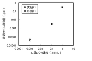
- 4 is a graph showing Li source LiOH concentration dependence of the amount of lithium transferred per hour in Examples and Comparative Examples according to the first embodiment of the present invention.
- 5 is a graph showing Li source LiOH concentration dependence of the amount of lithium transferred per hour in Examples and Comparative Examples according to the second embodiment of the present invention.
- FIG. 4 is a graph showing the amount of lithium transferred per hour from a 0.001 mol/L LiOH aqueous solution and a 1.0 mol/L LiCl aqueous solution in Examples and Comparative Examples according to the present invention.
- 1 is a schematic diagram of a lithium recovery device for explaining a conventional lithium recovery method using an electrodialysis method; FIG.
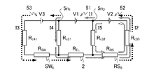
- the lithium recovery apparatus 10 includes a processing tank 1, an electrolyte membrane (lithium ion conductive electrolyte membrane) 2 that partitions the processing tank 1, and It comprises a coated first electrode 31 and a second electrode 32, a third electrode 33, a sub-electrode 41, and three power sources, a sub-power source 53, a first power source 51, and a second power source 52, connected in series.
- Lithium recovery device 10 may further comprise an agitator 72 .
- the treatment tank 1 consists of a supply tank (first tank) 11 containing a Li-containing aqueous solution SW such as seawater and a recovery tank (second tank) 13 containing a Li-recovering aqueous solution RS via an electrolyte membrane 2.
- a first electrode 31 is arranged on the supply tank 11 side, and a second electrode 32 is arranged on the recovery tank 13 side.
- the sub-electrode 41 and the third electrode 33 are provided in the supply tank 11 and the recovery tank 13, respectively, separated from the electrolyte membrane 2 .
- the first power supply 51 has a positive (+) pole connected to the first electrode 31 and a negative (-) pole connected to the second electrode 32 .
- the second power supply 52 is connected in series with the negative pole of the first power supply 51 , that is, the positive pole is connected to the second electrode 32 and the negative pole is connected to the third electrode 33 .
- the auxiliary power supply 53 is connected in series with the positive electrode of the first power supply 51 , that is, the negative electrode is connected to the first electrode 31 and the positive electrode is connected to the auxiliary electrode 41 . Therefore, the lithium recovery device 10 according to the present embodiment differs from the conventional lithium recovery device (for example, the lithium recovery device 100 shown in FIG. 11) by the electrodialysis method in that the first power source 51 (power source 151 in FIG. 11) is Both electrodes 31 and 32 (electrodes 131 and 132 in FIG.
- the treatment tank 1 is made of a material that does not undergo deterioration such as corrosion even when it comes into contact with the Li-containing aqueous solution SW and the Li-recovery aqueous solution RS (for example, lithium hydroxide (LiOH) aqueous solution) including after Li recovery.
- the processing tank 1 may have a volume corresponding to the required processing capacity, and its shape and the like are not particularly limited.
- the electrolyte membrane 2 is an electrolyte that has lithium ion conductivity, does not conduct metal ions M n + other than Li + contained in the Li-containing aqueous solution SW, and preferably does not conduct electrons e ⁇ .
- Metal ions M n+ other than Li + include, for example, K + , Na + , Mg 2+ , Ca 2+ and the like when the Li-containing aqueous solution SW is seawater. More preferably, the electrolyte membrane 2 is a ceramic electrolyte having these properties. Specifically, lithium-lanthanum-titanium oxide (La 2/3-x Li 3x TiO 3 , also called LLTO) and the like can be mentioned.
- Such an electrolyte membrane 2 has a certain proportion of lattice defects, and since the size of the lattice defect sites is small, metal ions larger in diameter than Li + do not conduct.
- the first electrode 31 and the second electrode 32 are paired to apply a voltage across both surfaces of the electrolyte membrane 2 , and the first electrode 31 is in contact with the surface of the electrolyte membrane 2 on the supply tank 11 side.
- the second electrode 32 is provided in contact with the surface of the electrolyte membrane 2 on the recovery tank 13 side.
- the first electrode 31 is also paired with a third electrode 33 described below to apply a voltage.
- the first electrode 31 and the second electrode 32 apply a voltage to a wide range of the electrolyte membrane 2, while the Li-containing aqueous solution SW or the Li-recovering aqueous solution RS is in contact with a sufficient area of the surface of the electrolyte membrane 2. It preferably has a porous structure such as a network.
- the first electrode 31 has catalytic activity and electronic conductivity for the reaction of the following formula (1) and the reaction of the following formula (3), and is formed of an electrode material that is stable even when a voltage is applied in the Li-containing aqueous solution SW. Furthermore, it is preferable to use a material that can be easily processed into the above shape.
- the second electrode 32 has catalytic activity and electronic conductivity for the reaction of the following formula (5) and the reaction of the following formula (1), and is stable even when a voltage is applied in the Li recovery aqueous solution RS including after Li recovery. It is preferable that the electrodes are made of an electrode material that is suitable for use, and that the material can be easily processed into the shape described above.
- the first electrode 31 and the second electrode 32 are preferably made of, for example, platinum (Pt) as such an electrode material.
- carbon (C) may be applied to the first electrode 31 when the Li-containing aqueous solution SW contains Cl ⁇ .
- the following formula (3) represents a reaction in which Li + in the aqueous solution (Li-containing aqueous solution SW) moves into the electrolyte membrane 2 .
- the following formula (5) represents a reaction in which Li + in the electrolyte membrane 2 moves to an aqueous solution (aqueous solution RS for recovering Li).
- the sub-electrode 41 is an electrode for forming a higher potential than the surface of the electrolyte membrane 2 in the Li-containing aqueous solution SW. Therefore, it is preferable that the sub-electrode 41 is arranged in the supply tank 11 so as not to contact the electrolyte membrane 2 and the first electrode 31 and arranged parallel to the first electrode 31 . Furthermore, in order to keep the voltage V3 of the sub-power supply 53 small, it is preferable that the sub-electrode 41 be arranged close to the first electrode 31 to the extent that short-circuiting does not occur, as will be described later. Further, the sub-electrode 41 preferably has a mesh shape or the like so as to increase the contact area with the Li-containing aqueous solution SW.
- the sub-electrode 41 has catalytic activity and electronic conductivity for the reaction of the following formula (1), and is made of an electrode material that is stable even when a voltage is applied in the Li-containing aqueous solution SW.
- the secondary electrode 41 further has catalytic activity for the oxidation reaction, for example, the reaction of the following formula (2) in the case of chloride ions (Cl ⁇ ).
- the secondary electrode 41 is preferably made of, for example, carbon (C), platinum (Pt), or carbon in which platinum fine particles are supported as a catalyst.
- the third electrode 33 is an electrode for forming a potential lower than that of the surface of the electrolyte membrane 2 in the Li recovery aqueous solution RS. Therefore, the third electrode 33 is preferably arranged in the recovery tank 13 so as not to contact the electrolyte membrane 2 and the second electrode 32 and arranged parallel to the second electrode 32 . Furthermore, in order to keep the voltage V2 of the second power supply 52 small, it is preferable that the third electrode 33 be arranged close to the second electrode 32 to the extent that short-circuiting does not occur, as will be described later. Moreover, the third electrode 33 preferably has a mesh shape or the like so as to increase the contact area with the Li recovery aqueous solution RS.
- the third electrode 33 has catalytic activity and electronic conductivity for the reaction of the following formula (4), and is formed of an electrode material that is stable even when a voltage is applied in the Li recovery aqueous solution RS including after Li recovery. Platinum (Pt) is preferred.
- the third electrode 33 can be made of carbon (C), copper (Cu), or stainless steel, which is stable at a potential lower than the potential at which the reaction of the following formula (4) occurs. It is more preferable to carry functional Pt fine particles.
- a first power supply 51, a second power supply 52, and a sub-power supply 53 are DC power supplies that apply predetermined voltages V1, V2, and V3, respectively.
- the power supplies 52 are connected in series.
- the first power source 51 has a positive electrode connected to the first electrode 31 and a negative electrode connected to the second electrode 32 .
- the second power supply 52 has a positive electrode connected to the second electrode 32 and a negative electrode connected to the third electrode 33 .
- the secondary power supply 53 has a positive electrode connected to the secondary electrode 41 and a negative electrode connected to the first electrode 31 .
- connection node 5n1 between the first power supply 51 and the sub power supply 53 is connected to the first electrode 31, and the connection node 5n2 between the first power supply 51 and the second power supply 52 is connected to the second electrode 32.
- the first power supply 51 applies a voltage V1 across the electrolyte membrane 2 to generate a potential gradient for conducting Li + in the electrolyte membrane 2 .
- the second power supply 52 applies a voltage V2 that forms a potential lower than that of the surface of the electrolyte membrane 2 to the aqueous solution RS for recovering Li, so that electrons e ⁇ are transferred from the recovery tank 13 side of the electrolyte membrane 2 to the supply tank 11 side. Suppress conduction.
- the first power source 51 and the second power source 52 which are connected in series, serve as one main power source between the Li-containing aqueous solution SW and the Li-recovering aqueous solution RS, and the voltage V1 applied between both surfaces of the electrolyte membrane 2 Also, a large voltage (V1+V2) is applied.
- the auxiliary power supply 53 applies a voltage V3 to the Li-containing aqueous solution SW to form a potential higher than that of the surface of the electrolyte membrane 2, and electrostatically charges Li + near the surface of the electrolyte membrane 2, which has a relatively low potential. While they are unevenly distributed by attraction, anions such as Cl ⁇ are kept away by electrostatic repulsion.
- the stirrer 72 is a device for circulating the Li-containing aqueous solution SW in the supply tank 11 so that the Li-containing aqueous solution SW in contact with the first electrode 31 is continuously replaced during operation, and is provided as necessary. Similarly, the stirrer 72 may circulate the Li recovery aqueous solution RS in the recovery tank 13 so that the Li recovery aqueous solution RS in contact with the second electrode 32 is continuously replaced.
- a well-known device can be applied to the stirrer 72.
- a circulation device 71 may be provided for circulating the aqueous solutions SW and RS by means of pumps between the baths 11 and 13 and circulation baths provided outside the processing bath 1 (see the modification shown in FIG. 4).
- the Li-containing aqueous solution SW is a Li source, and is an aqueous solution containing lithium ions Li + and other metal ions M n+ such as K + , Na + , and Ca 2+ .
- an aqueous solution for example, seawater, waste brine after extracting salt from seawater, underground water such as hot spring water, used lithium ion secondary batteries, etc. are crushed, roasted and dissolved in acid, and if necessary, and pH-adjusted aqueous solution.
- the Li recovery aqueous solution RS is a solution for accommodating lithium ions Li + recovered from the Li-containing aqueous solution SW.
- the Li recovery aqueous solution RS is preferably an aqueous solution that does not contain metal ions (such as Na + ) other than lithium ions Li + , and further contains anions other than OH ⁇ ,
- metal ions such as Na +
- an aqueous solution containing no halide ions is preferable, and pure water may be used.
- the Li recovery aqueous solution RS should be an aqueous solution containing Li + (lithium hydroxide (LiOH) aqueous solution) at the start of recovery (at the start of power application). preferable.
- Li + lithium hydroxide (LiOH) aqueous solution
- the lithium recovery device 10 may further include a heating device that heats the electrolyte membrane 2 via the Li-containing aqueous solution SW or the Li-recovery aqueous solution RS in order to set the electrolyte membrane 2 to a predetermined temperature.
- a heating device that heats the electrolyte membrane 2 via the Li-containing aqueous solution SW or the Li-recovery aqueous solution RS in order to set the electrolyte membrane 2 to a predetermined temperature.
- a known heater that heats a liquid can be applied to the heating device, and preferably has a temperature control function.
- the heating device is, for example, an immersion type (immersion type), and is installed by being immersed in the Li recovery aqueous solution RS in the recovery tank 13 .
- the heating portion of the heating device that is immersed in the Li-recovery aqueous solution RS is made of a material that does not deteriorate such as corrosion even when it comes into contact with the Li-recovery aqueous solution RS, like the treatment tank 1 .
- the heating device is sufficient as long as it can set the electrolyte membrane 2 to a predetermined temperature, and the Li-containing aqueous solution SW and the Li-recovering aqueous solution RS need not be uniform in liquid temperature.
- the stirrer 72 may be provided depending on the volume of the processing tank 1 and the like.
- the temperature of the electrolyte membrane 2 may be above the freezing point and below the boiling point of the aqueous solutions SW and RS, and is preferably high as described later.
- the lithium recovery apparatus 10 may further include a liquid level sensor or the like to sense fluctuations in the amounts of the Li-containing aqueous solution SW and the Li-recovery aqueous solution RS during operation.
- a liquid level sensor or the like to sense fluctuations in the amounts of the Li-containing aqueous solution SW and the Li-recovery aqueous solution RS during operation.
- CO 2 carbon dioxide
- Li 2 CO 3 lithium carbonate
- the lithium recovery device 10 is preferably configured so that the Li recovery aqueous solution RS is not exposed to the atmosphere.
- the lithium recovery device 10 is designed so as not to fill the interior with gases such as O 2 and H 2 generated during operation (due to the reactions of formulas (1), (4), and (2)) and Cl 2 .
- gases such as O 2 and H 2 generated during operation (due to the reactions of formulas (1), (4), and (2)) and Cl 2 .
- the lithium recovery apparatus 10 discharges the gas generated from the aqueous solutions SW and RS to the outside of the processing tank 1 and prevents the outside air from flowing into the supply tank 11 and the recovery tank 13 of the processing tank 1, for example.
- a check valve is preferably provided.
- Lithium recovery method A lithium recovery method according to a first embodiment of the present invention will be described with reference to FIGS. 2 and 3.
- FIG. The lithium recovery method according to the present embodiment is performed as follows by using the lithium recovery device 10 according to the first embodiment shown in FIG. 2, the stirrer 72 is omitted.
- the sub power supply 53, first power supply 51, and second power supply 52 connected in series can be regarded as one power supply (referred to as power supply 50).
- the first power supply 51 and the second power supply 52 can be regarded as one power supply (referred to as main power supplies 51-52).
- the power supply 50 applies a positive voltage (V3+V1+V2) to the sub-electrode 41 with respect to the third electrode 33 .
- the main power supply 51-52 applies a positive voltage (V1+V2) to the first electrode 31 with respect to the third electrode 33. Then, the following reactions occur in the Li-containing aqueous solution SW in the supply tank 11 .
- hydroxide ions (OH ⁇ ) in the Li-containing aqueous solution SW cause the reaction of the following formula (1) to release electrons e ⁇ to form water (H 2 O) and oxygen (O 2 ) are generated, and electrons e ⁇ are emitted to the sub-electrode 41 and the first electrode 31 .
- the Li-containing aqueous solution SW contains halide ions such as chloride ions (Cl ⁇ )
- the reaction of the following formula (2) further occurs to release electrons e ⁇ and generate chlorine (Cl 2 ).
- a gas corresponding to the type of anions contained in the Li-containing aqueous solution SW is generated.
- Li + in the Li-containing aqueous solution SW moves into the electrolyte membrane 2 in order to maintain the charge balance. occurs on the surface of the electrolyte membrane 2 , that is, in the vicinity of the first electrode 31 .
- the application of the voltage V3 by the sub-power supply 53 forms a potential gradient in which the potential of the sub-electrode 41 is higher than that of the surface of the electrolyte membrane 2 (first electrode 31). Therefore, OH - and Cl - are attracted to the sub-electrode 41 by electrostatic attraction. Further, since the potential of the sub-electrode 41 is sufficiently high, Cl ⁇ is easily oxidized in the vicinity thereof, and the reaction of formula (2) tends to occur at high speed. Therefore, in the vicinity of the sub-electrode 41, Cl ⁇ decreases due to the reaction of formula (2). Then, Cl ⁇ is further attracted to the sub-electrode 41 by electrostatic attraction. As a result, in the vicinity of the first electrode 31, which has a lower potential than the sub-electrode 41, the Cl.sup.- concentration becomes relatively low, and the reaction of formula (1) mainly occurs.
- the following reactions occur.
- the voltage (V1+V2) is applied by the main power supply 51-52, and the H 2 O in the Li recovery aqueous solution RS is supplied with electrons e ⁇ , whereby the reaction of the following formula (4) to generate hydrogen (H 2 ) and OH ⁇ .
- H + decreases in the vicinity of the third electrode 33, so Li + in the electrolyte membrane 2 moves to the Li recovery aqueous solution RS on the surface of the electrolyte membrane 2, that is, in the vicinity of the second electrode 32.
- the reaction of (5) is produced.
- the second power supply 52 applies a positive voltage V2 of a predetermined magnitude based on the voltages V1 and V3 to the second electrode 32 and the third electrode 33 . Then, in the vicinity of the second electrode 32, OH - in the Li recovery aqueous solution RS undergoes the reaction of the following formula (1), electrons e - are emitted to the second electrode 32, and H 2 O and O 2 are generated. generate. As a result, in the vicinity of the second electrode 32, a charge imbalance occurs due to excess cations due to the reaction of the following formula (1) and the reaction of the following formula (5).
- the electrolyte membrane 2 has a potential gradient in which the potential of the surface on the opposite side (the recovery tank 13 side) is low. It jumps (hops) to a nearby lattice defect site on the deep side of the electrolyte membrane 2 .
- Li + repeatedly migrates from the lattice defect site of the electrolyte membrane 2 to the lattice defect site in the vicinity thereof, and finally, as the reaction of formula (5), the lattice defect site on the surface of the recovery tank 13 is to the Li recovering aqueous solution RS.
- Li + at the lattice defect sites on the surface of the electrolyte membrane 2 on the side of the supply tank 11 moves to the deep part of the electrolyte membrane 2 .
- the application of the voltage V3 by the auxiliary power supply 53 forms a potential gradient in the Li-containing aqueous solution SW, so that the Li-containing aqueous solution SW converts Cl ⁇ Even if it contains Cl ⁇ , the concentration of Cl ⁇ in the vicinity of the electrolyte membrane 2 is relatively low. Therefore, less Cl ⁇ is adsorbed to the surface of the electrolyte membrane 2, and inhibition of the reaction of formula (3) is suppressed.
- Li + migration between lattice defect sites in 2 is facilitated.
- the Li + movement in the electrolyte membrane 2 becomes faster as the Li + concentration gradient in the electrolyte membrane 2 increases. Therefore, the stronger the electric field generated in the Li-containing aqueous solution SW by the voltage V3 of the secondary power supply 53, and the stronger the electric field generated in the Li-recovering aqueous solution RS by the voltage V2 of the second power supply 52, the reaction of formula (3) and the reaction of formula (5) becomes faster, and Li + in the Li-containing aqueous solution SW can be moved at high speed into the electrolyte membrane 2 and further to the Li-recovering aqueous solution RS for recovery.
- the stronger the electric field generated in the Li-containing aqueous solution SW the faster the reaction of the formula (3) can be performed even if the Li-containing aqueous solution SW has a low Li + concentration.
- the stronger the electric field generated in the Li-containing aqueous solution SW the less likely the reaction of formula (3) is inhibited by Cl.sup.- .
- the movement of Li + in the electrolyte membrane 2 also becomes faster as the potential gradient in the electrolyte membrane 2 increases, that is, as the voltage V1 of the first power supply 51 increases.
- the reaction of 5) becomes faster, and Li + in the electrolyte membrane 2 can be moved to the aqueous solution RS for recovering Li.
- the reaction of the following formula (4) occurs in the vicinity of the first electrode 31 in the Li-containing aqueous solution SW, causing H 2 will occur. Since this reaction receives electrons e ⁇ , the movement of electrons e ⁇ (see FIG. 2) in the vicinity of the first electrode 31 is opposite to the reaction of the following formula (1).
- the electrolyte membrane 2 When the vicinity of the first electrode 31, i.e., the surface of the electrolyte membrane 2 on the side of the supply tank 11, reaches the generation potential of H2 , the electrolyte membrane 2 is formed regardless of the magnitude of the voltage V1 applied across both surfaces of the electrolyte membrane 2. A potential at which some of the metal ions are reduced (for example, if the electrolyte membrane 2 is LLTO, Ti 4+ +e ⁇ ⁇ Ti 3+ ) is reached, and the electrolyte membrane 2 develops electron transferability. Then, the electrons e ⁇ conducting through the electrolyte membrane 2 generate Joule heat, so the energy efficiency in moving Li + sharply decreases.
- the voltage V3 should be less than the voltage at which electrolysis of water occurs, and preferably greater within this range. Note that the voltage at which water electrolysis occurs is actually determined by the theoretical voltage ( 1.229 V, 25° C.). Furthermore, in the present embodiment, even if the voltage V3 is the above value or more, if the voltage V2 is larger than the voltage V3 by a certain amount or more, the potential of the surface of the electrolyte membrane 2 facing the supply tank 11 is less than the H 2 generation potential. voltage V3 can be set up to a higher value because the electrolysis of water does not occur.
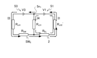
- the lithium recovery apparatus 10 includes a second power supply 52, a first power supply 51, a secondary power supply 53, a Li-containing aqueous solution SW E , an electrolyte membrane 2, an aqueous Li recovery solution RS E , a second It includes a closed circuit in which two power sources 52 are connected in a circular fashion.
- the positive electrode of the first power supply 51 and the negative electrode of the sub power supply 53 (connection node 5n 1 ) are connected to the electrolyte membrane 2 and the Li-containing aqueous solution SW E via the first electrode 31, respectively.
- the negative electrode of the first power source 51 and the positive electrode (connection node 5n 2 ) of the second power source 52 are connected via the second electrode 32 to the electrolyte membrane 2 and the aqueous Li recovery solution RSE , respectively. Therefore, in the lithium recovery device 10, current can flow either from the connection node 5n 1 to the electrolyte membrane 2 or from the Li-containing aqueous solution S E or the electrolyte membrane 2 to the connection node 5n 1 .
- connection node 5n2 the resistance between the first electrode 31 and the second electrode 32, the movement resistance of Li +
- R EL the resistance of the Li-containing aqueous solution S E (the resistance between the first electrode 31 and the sub-electrode 41)
- R SW the resistance of the Li recovery aqueous solution RS E (resistance between the second electrode 32 and the third electrode 33 )
- the lithium recovery device 10 has a reaction resistance R c41 due to the reaction (O 2 generation) of formula (1) and the reaction (Cl 2 generation) of formula (2) at the sub electrode 41 , and the reaction resistance R c41 at the first electrode 31 of formula (1) and the reaction resistance R c31 due to the reaction of formula (2).
- the lithium recovery apparatus 10 includes, as a second circuit, a closed circuit in which the second power source 52, the first power source 51, the electrolyte membrane 2, the Li recovery aqueous solution RS E , and the second power source 52 are connected in a ring in this order. . As shown in FIG.
- currents I4, I1 and I2 are supplied to this closed circuit as indicated by gray arrows by a first power supply 51 and a second power supply 52 (main power supplies 51-52) connected in series. flow.
- a current branching from the current I1 (from the connection node 5n1 ) and flowing toward the electrolyte membrane 2 via the first electrode 31 is denoted by I4.
- the lithium recovery apparatus 10 connects ammeters (not shown) in series to the first power supply 51 and the auxiliary power supply 53, respectively, and applies voltages V1 and V3 while measuring the currents I1 and I3. Just do it.
- the lower the resistance R sw between the first electrode 31 and the sub-electrode 41 and the reaction resistance R c41 at the sub-electrode 41 the stronger the electric field generated in the Li-containing aqueous solution SW even if the voltage V3 is small, and the effect is high. is obtained.
- the reaction resistance R c41 decreases as the area of the sub-electrode 41 immersed in the Li-containing aqueous solution SW increases and as the catalytic activity of the sub-electrode 41 for the reaction of formula (1) increases.
- the resistance R SW decreases as the areas of the first electrode 31 and the sub-electrode 41 immersed in the Li-containing aqueous solution SW increase and as the distance between them decreases.
- the higher the electronic conductivity of the Li-containing aqueous solution SW the lower the resistance R SW .
- the reaction of formula (1) or further the reaction of formula (2) at the first electrode 31 such that the current I4 flows from the positive electrode (connection node 5n 1 ) of the first power supply 51 to the first electrode 31, and the secondary electrode
- the total reaction amount of the reaction of formula (1) and the reaction of formula (2) at 41 is directly related to the amount of Li + moving through the electrolyte membrane 2, and Li + corresponding to the current amount of (I3 + I4) It moves across the electrolyte membrane 2 .
- the total current amount of (I3+I4) that is, the current I1 is as large as possible.
- I1>I3 including a margin so that I1 ⁇ I3 does not occur.
- I1>I3 I4>0
- O 2 is generated even at the first electrode 31 .
- the voltage V1 can be set to a sufficient magnitude as described below.
- the voltage V1 that is, the potential difference between both surfaces of the electrolyte membrane 2 causes some of the metal ions constituting the electrolyte membrane 2 to be reduced (for example, if the electrolyte membrane 2 is LLTO, Ti 4+ +e ⁇ ⁇ Ti 3+ ) voltage (referred to as electrolyte reduction voltage as appropriate)
- the electrolyte membrane 2 can conduct electrons e ⁇ from the collection tank 13 side to the supply tank 11 side (see Patent Document 2). Therefore, even if the voltage V1 is further increased, the amount of movement of Li + does not increase by the amount of the increase in the voltage V1, and the energy efficiency decreases.
- a second power supply 52 connected between the second electrode 32 and the third electrode 33 applies a voltage V2 to create an appropriate potential difference with the second electrode 32 being positive. Then, the electrons e ⁇ supplied from the third electrode 33 to the Li recovery aqueous solution RS move from the second electrode 32 on the surface of the electrolyte membrane 2 to the positive electrode of the second power supply 52 , and the potential of the second electrode 32 becomes O 2 It is maintained as high as the generated potential. Since the O 2 generation potential is higher than the reduction potential of the metal ions forming the electrolyte membrane 2, the electrolyte membrane 2 does not conduct electrons e ⁇ regardless of the potential difference between the two surfaces.
- the voltage V1 can be set to a voltage higher than the electrolyte reduction voltage of the electrolyte membrane 2 .
- the voltage V2 when such a large voltage V1 is applied without applying the voltage V2, electrons e ⁇ are taken in from the negative electrode side (recovery tank 13 side) of the electrolyte membrane 2 to reduce metal ions. .
- Such a phenomenon is likely to occur particularly with transition metal ions.
- the application of the voltage V2 does not allow the electrolyte membrane 2 to reach the reduction potential of the metal ions, and the electrolyte membrane 2 does not transfer electrons e ⁇ .
- the lithium recovery apparatus 10 includes, as a third circuit, a closed circuit composed of a second power supply 52 and an aqueous Li recovering solution RSE .
- I2 flows.
- a current I5 branches from the current I2 and flows to the second electrode 32 (from the connection node 5n2 ).
- the lithium recovery device 10 is configured as follows so that the current I5 may or may not flow in such a direction (does not flow in the opposite direction), that is, I5 ⁇ 0.
- R EL is the resistance of the electrolyte membrane 2 (the resistance between the first electrode 31 and the second electrode 32, the movement resistance of Li + ); ) is represented as R RS .
- the lithium recovery device 10 has a reaction resistance R c33 due to the reaction (H 2 generation) of the formula (4) at the third electrode 33 and a reaction resistance R c33 due to the reaction (O 2 generation) of the formula (1) at the second electrode 32 Further includes R c32 .
- the first circuit is represented by the following equation (6)
- the second circuit is represented by the following equation (7)
- the third circuit is represented by the following equation (8).
- the resistance of the electrodes 31, 32, 41, 33 and wiring is ignored.
- the following formula (9) is obtained from the formulas (6) and (7), and the following formula (10) is obtained from the formulas (7) and (8).
- the current I1 is represented by the following formula (11) from the following formula (10).
- the current I2 is represented by the following formula (12) from the formula (8).
- the current I3 is represented by the following formula (13) from the following formula (9).
- the following equation (14) should be established. Solving the equation (14) yields the equation (15). Also, substituting the following equation (12) for I2 in the following equation (11) and the following equation (13) for I3, respectively, and solving for I1 yields the following equation (16). Substituting the formula (16) into the formula (15) yields the formula (17).
- the lithium recovery apparatus 10 connects ammeters (not shown) in series to the first power source 51 and the second power source 52, respectively, and applies voltages V1 and V2 while measuring the currents I1 and I2. do it.
- the lower the resistance R RS between the second electrode 32 and the third electrode 33 and the reaction resistance R c33 at the third electrode 33 the higher the effect can be obtained even if the voltage V2 is small.
- the reaction resistance R c33 decreases as the area of the third electrode 33 immersed in the Li recovery aqueous solution RS increases and as the catalytic activity of the third electrode 33 for the reaction of formula (4) increases.
- the resistance R RS decreases as the areas of the second electrode 32 and the third electrode 33 immersed in the Li recovering aqueous solution RS become larger and the distance between them becomes shorter. Also, the resistance R RS is lower as the electronic conductivity of the aqueous solution RS for Li recovery is higher.
- reaction amount of the reaction of formula (1) occurring at the second electrode 32 that is, the magnitude of the current I5 ( ⁇ 0) is not directly related to the amount of movement of Li + .
- the voltage V2 is insufficient with respect to the voltages V1 and V3 and the equation (17) does not hold, then I5 ⁇ 0, current flows from the second electrode 32 to the negative electrode of the auxiliary power supply 53, and the second electrode 32 also has the equation Reaction (4) comes to occur.
- the voltage V1 is represented by the following equation (18).
- R c32 ′ is the reaction resistance due to the reaction (H 2 generation) of formula (4) at the second electrode 32 .
- ⁇ R c32 ′) is the reduction potential of the metal ions constituting the electrolyte membrane 2 (in the case of Ti, , Ti 4+ ⁇ Ti 3+ ; ⁇ 0.488 V vs. SHE).
- the larger the voltage V2 the larger the Li + concentration gradient in the electrolyte membrane 2 and the faster the movement of Li + in the electrolyte membrane 2 .
- the current I5 increases, and O 2 is generated near the second electrode 32 ( (1) and generation of H 2 (reaction (4)) in the vicinity of the third electrode 33 increase more than the amount of moving Li + , and the energy efficiency decreases.
- the voltage V2 satisfies I1>I2, as described above, if the difference
- the resistance R RS decreases due to an increase in the Li + concentration of the Li recovery aqueous solution RS
- a margin of It is preferable to set the voltage V2 so that I1 ⁇ I2.
- the liquid amounts of the Li-containing aqueous solution SW and the Li-recovery aqueous solution RS decrease. 11 is preferred.
- the Li recovery aqueous solution RS it is preferable to add water (H 2 O) or the like to the recovery tank 13 periodically or all the time.
- the liquid levels in the supply tank 11 and the recovery tank 13 are uniform during operation.
- Lithium carbonate (Li 2 CO 3 ) is produced by, for example, carbon dioxide (CO 2 ) bubbling in the aqueous solution RS for recovering Li after completion of the operation, for example, after concentrating Li by evaporating water if necessary. Li can be recovered by separating and depositing Li. Alternatively, after lithium carbonate is produced, lithium hydroxide (LiOH) is produced in a supersaturated state by cooling or by evaporating water, and Li can be recovered by depositing it.
- carbon dioxide CO 2
- Li lithium hydroxide
- the auxiliary power supply 53 is connected in series with the positive electrode of the first power supply 51 that applies the voltage V1 between both surfaces of the electrolyte membrane 2.
- the secondary electrode 41 of Li + is unevenly distributed in the vicinity of the electrolyte membrane 2 while Cl ⁇ is kept away from the electrolyte membrane 2 .
- inhibition of dissolution of Li + in the Li-containing aqueous solution SW into the electrolyte membrane 2 due to adsorption of Cl ⁇ to the surface of the electrolyte membrane 2 is suppressed. Therefore, Li + can be efficiently recovered by using a Li source such as seawater containing Cl ⁇ at a high concentration as the Li-containing aqueous solution SW.
- the Li-containing aqueous solution SW has a relatively high Li + concentration in the vicinity of the electrolyte membrane 2 , a concentration gradient of Li + is efficiently formed in the electrolyte membrane 2 , and movement of Li + in the electrolyte membrane 2 is suppressed. It can be faster. Such an effect becomes more remarkable when the Li-containing aqueous solution SW has a low Li + concentration.
- a second power supply 52 is provided which is connected in series to the negative electrode of the electrolyte membrane 2.
- the third electrode 33 having a potential lower than that of the surface of the electrolyte membrane 2 and setting this potential difference, that is, the voltage V2 of the second power supply 52 corresponding to the voltage V1
- the electrolyte membrane 2 reaches the reduction potential of the metal ion. Even if a large potential difference is generated between the two surfaces, the electron e ⁇ is difficult to conduct. As a result, the recovery rate of Li + can be increased corresponding to the potential gradient in the electrolyte membrane 2 .
- the potential gradient is efficiently formed in the electrolyte membrane 2 by the first power source 51 , and It is possible to increase the moving speed of Li + at . Furthermore, when the voltage V2 of the second power supply 52 is increased in accordance with the increase of the voltage V1 of the first power supply 51, the concentration gradient of Li + is formed in the electrolyte membrane 2 more efficiently, and the Li + concentration in the electrolyte membrane 2 movement can be further accelerated.
- the movement of Li + in the electrolyte membrane 2 becomes faster as the temperature becomes higher as well as the voltage V1. Therefore, it is preferable that the temperature of the electrolyte membrane 2 is high. Also, the resistances R EL , R SW , R RS of the electrolyte membrane 2 and the aqueous solutions SW, RS and the reaction resistances at the electrodes 31 , 32 , 41 , 33 are lower as the temperature is higher.
- the applicable temperature range is from the freezing point to the boiling point of the aqueous solutions SW and RS, preferably 20° C. or higher.
- the Li source containing chloride ions is in direct contact with the surface of the electrolyte membrane on the supply tank side. Therefore, even if the chloride ions are kept away by the electrostatic repulsion due to the voltage application from the auxiliary power source, the catalytic activity is impaired to some extent in long-term operation.
- the higher the pH of the aqueous solution on the Li + supply side of the electrolyte membrane with respect to the recovery side aqueous solution the higher the Li + mobility. For example, when seawater is used as the Li source, the seawater is weakly alkaline.
- the aqueous solution on the recovery side changes from pure water before the start to an aqueous LiOH solution as the process progresses, and the concentration increases and the pH also increases. It will be higher with respect to the supply side and the Li + mobility will decrease.
- the following configuration was adopted.
- a lithium recovery device and a lithium recovery method according to modifications of the first embodiment of the present invention will be described with reference to FIGS. 4 and 5.
- a lithium recovery apparatus 10A includes a processing tank 1, an electrolyte membrane (lithium ion conductive electrolyte membrane) 2 that partitions the processing tank 1, and an ion exchange membrane 62. , a first electrode 31 and a second electrode 32 coated on each side of the electrolyte membrane 2, a third electrode 33, a sub-electrode 41, and three power sources 53, 51, 52 connected in series.
- the lithium recovery device 10A may further include a circulation device (circulation means) 71 and an agitator 72 .
- the treatment tank 1 includes a supply tank (first tank) 11 containing a Li-containing aqueous solution SW such as seawater and an intermediate tank 12 containing a Li-containing aqueous solution AS in one direction by an ion exchange membrane 62 and an electrolyte membrane 2 . , and a recovery tank (second tank) 13 containing an aqueous solution RS for Li recovery.
- the ion exchange membrane 62 separates the supply tank 11 and the intermediate tank 12
- the electrolyte membrane 2 separates the intermediate tank 12 and the recovery tank 13 .
- a sub-electrode 41 is provided in the supply tank 11 .
- the third electrode 33 is provided inside the recovery tank 13 so as to be separated from the electrolyte membrane 2 . Therefore, the lithium recovery device 10A according to this modification differs from the lithium recovery device 10 according to the embodiment shown in FIG. is added, and the supply tank 11 is further partitioned into the supply tank 11 and the intermediate tank 12 by the ion exchange membrane 62 .
- the ion exchange membrane 62 conducts cations containing at least Li + .
- the ion exchange membrane 62 can prevent the Li-containing aqueous solution AS in the intermediate tank 12 from containing halide ions such as Cl ⁇ .
- the ion exchange membrane 62 is a cation exchange membrane that allows cations to pass through and anions to be blocked, and a monovalent cation selective permeation ion exchange membrane that allows only monovalent cations such as Li + , K + , and Na + to pass through.
- Membranes, bipolar monovalent ion permselective ion exchange membranes that allow monovalent ions to permeate, and the like can be applied.
- Known ion-exchange membranes can be applied.
- SELEMION registered trademark
- NOSEPTA CIMS manufactured by Astom Co., Ltd.
- the lithium recovery device 10A it is preferable that the distance between the sub-electrode 41 and the first electrode 31 is short as in the above-described embodiment. It is preferable that the intermediate tank 12 is arranged so as to be short.
- the circulation device 71 includes, for example, a pump and a filter for removing dust and the like.
- the Li-containing aqueous solution SW is seawater, hot spring water, or the like, it is preferable to apply the voltage while circulating the Li-containing aqueous solution SW from these supply sources into the supply tank 11 .
- the Li + concentration of the Li-containing aqueous solution SW is maintained substantially constant even if the recovery of Li + progresses, and even with a low-concentration Li aqueous solution, the Li recovery rate does not easily decrease, and the recovery of Li is difficult for a long period of time. Continuous operation is possible.
- the Li-containing aqueous solution SW in the supply tank 11 may be exchanged in the circulation device 71 every operation for a certain period of time.
- the lithium recovery apparatus 10A may have a structure in which the supply tank 11 is open to the outside (for example, into the sea) through a filter or the like.
- the Li-containing aqueous solution AS is an aqueous solution obtained by removing anions other than OH ⁇ , such as Cl ⁇ , from the Li-containing aqueous solution SW stored in the supply tank 11 .
- the Li-containing aqueous solution AS can be pure water in the same manner as the Li-recovering aqueous solution RS, and is preferably an aqueous solution containing Li + (LiOH aqueous solution). .
- the auxiliary power supply 53 applies the voltage V3 to the Li-containing aqueous solution AS in contact with the surface of the electrolyte membrane 2 on the supply side, as in the above-described embodiment, to form a higher potential than the surface of the electrolyte membrane 2, Li + is unevenly distributed near the surface of the electrolyte membrane 2 by electrostatic attraction.
- the Li-containing aqueous solution SW on the supply tank 11 side generates a high potential difference between both surfaces of the ion-exchange membrane 62, that is, between the Li-containing aqueous solution SW and the Li-containing aqueous solution AS, so that the Li-containing aqueous solution SW
- the cations containing Li + in the solution are transferred to the Li-containing aqueous solution AS.
- the intermediate tank 12 may also be provided with a circulation device 71 or a stirrer 72 .
- the circulation device 71 for circulating the Li-containing aqueous solution AS may include a sedimentation tank for precipitating cations other than Li + in the Li-containing aqueous solution AS, and a filter for preventing the precipitate from returning to the intermediate tank 12. .
- a lithium recovery method according to a modification of the first embodiment of the present invention will be described with reference to FIG. 5, the circulation device 71 and the stirrer 72 are omitted.
- the lithium recovery method according to this modification can be performed in the same manner as the lithium recovery method according to the first embodiment by using a lithium recovery device 10A according to the modification of the first embodiment shown in FIG.
- secondary power supply 53 applies voltage V3, so that cations such as Li + in Li-containing aqueous solution SW permeate ion-exchange membrane 62 and move to Li-containing aqueous solution AS. Furthermore, as described in the above embodiment, Li + is attracted to the surface of the electrolyte membrane 2 (first electrode 31) by electrostatic attraction in the Li-containing aqueous solution AS due to the potential gradient due to the voltage V3. Reactions caused by the application of voltages V1, V2, and V3 are as described in the above embodiment.
- the Li-containing aqueous solution AS contains Li + , K + , Na + and the like. Only monovalent cations migrate, and divalent and trivalent cations such as Ca 2+ do not migrate. Therefore, the amount of precipitate in the Li-containing aqueous solution AS that contacts the supply side surface of the electrolyte membrane 2 can be reduced, and the movement of Li + from the Li-containing aqueous solution AS to the Li-recovering aqueous solution RS is not hindered.
- the resistance R SW of the Li-containing aqueous solution SW E is the sum of the resistances of the Li-containing aqueous solutions SW and AS between the first electrode 31 and the sub-electrode 41 and the ion exchange membrane 62 .
- the Li-containing aqueous solution AS is pure water (not containing Li + ) or a low-concentration LiOH aqueous solution at the start of recovery, first, only the auxiliary power supply 53 is operated to add Li + to the Li-containing aqueous solution AS. It is preferable to further operate the first power source 51 and the second power source 52 after moving and reaching a predetermined concentration.
- anions such as chloride ions are shielded from the Li-containing aqueous solution in the supply tank, anions are not contained in the aqueous solution contacting the supply side surface of the electrolyte membrane. This makes it possible to make the first electrode provided on this surface of the electrolyte membrane more difficult to deteriorate.
- the aqueous solution in contact with the supply side surface of the electrolyte membrane can be made to have a high pH, and Li + migration with respect to the applied voltage The higher the temperature, the higher the energy efficiency.
- the lithium recovery apparatus includes two or more ion exchange membranes that conduct cations including Li + , the processing tank is divided into four or more, and two or more are provided between the supply tank and the recovery tank at both ends. An intermediate tank may be provided. Such a lithium recovery device is constructed such that all ion exchange membranes are sandwiched between the first electrode and the secondary electrode in the feed tank. By providing a plurality of ion exchange membranes, anions such as chloride ions are more shielded from the Li-containing aqueous solution in the supply tank, so that more anions are contained in the aqueous solution in contact with the supply side surface of the electrolyte membrane.
- monovalent cation permselective ion exchange membranes and bipolar type monovalent ion permselective ion exchange membranes have sufficient resistance to strong alkalinity. Many don't have it.
- the aqueous solution obtained by removing anions from the Li-containing aqueous solution SW tends to be strongly alkaline if the concentration of cations is high.
- Li + is removed from the Li-containing aqueous solution AS by moving it to the Li-recovering aqueous solution RS or by precipitating monovalent cations other than Li + .
- the lithium recovery device can be equipped with a combination of a cation exchange membrane that conducts cations including multivalent ions and a monovalent ion selective permeable ion exchange membrane.
- increasing the number of ion-exchange membranes increases the resistance between the first electrode and the sub-electrode, making it difficult to generate a strong electric field if the voltage applied by the sub-power supply is less than the voltage at which electrolysis of water occurs. is. Therefore, only some of the plurality of ion-exchange membranes are arranged between the first electrode connected to the sub-power supply and the sub-electrode, and voltage is applied to the other ion-exchange membranes by the additional sub-power supply. preferably.
- a lithium recovery apparatus 10B includes a processing tank 1, an electrolyte membrane (lithium ion conductive electrolyte membrane) 2 partitioning the processing tank 1, and Ion exchange membranes 61 and 62, a first electrode 31 and a second electrode 32 coated on each side of the electrolyte membrane 2, a third electrode 33, sub-electrodes 41, 42 and 43, three power sources 53 and 51 connected in series, 52 and a secondary power supply 54 .
- the lithium recovery device 10B may further include a circulation device 71 and a stirrer 72 as necessary (see FIGS. 1 and 4).
- the processing tank 1 is divided in one direction by the two ion exchange membranes 61 and 62 and the electrolyte membrane 2 into a supply tank (first tank) 11 containing the Li-containing aqueous solution SW and an intermediate tank containing the Li-containing aqueous solution AS'. It is partitioned into four tanks 12a, an intermediate tank 12b containing the Li-containing aqueous solution AS, and a recovery tank (second tank) 13 containing the Li-recovering aqueous solution RS. Specifically, the ion exchange membrane 61 partitions the supply tank 11 and the intermediate tank 12a, the ion exchange membrane 62 partitions the intermediate tank 12a and the intermediate tank 12b, and the electrolyte membrane 2 partitions the intermediate tank 12b and the recovery tank 13.
- the third electrode 33 is provided in the recovery tank 13 so as to be separated from the electrolyte membrane 2 .
- the sub-electrodes 41 and 43 are spaced apart from each other in the intermediate tank 12 a , the sub-electrode 41 facing the ion-exchange membrane 62 and the sub-electrode 43 facing the ion-exchange membrane 61 .
- a sub-electrode 42 is provided in the supply tank 11 .
- the secondary power supply 54 has a positive electrode connected to the secondary electrode 42 and a negative electrode connected to the secondary electrode 43 . Therefore, the lithium recovery device 10B according to the present modification is different from the lithium recovery device 10A according to the modification shown in FIG. It has a configuration in which a sub-power source 54 for applying a voltage between both surfaces of the film 61 and sub-electrodes 42 and 43 connected to the sub-power source 54 are added.
- the ion exchange membrane 61 is provided on the Li + supply side with respect to the electrolyte membrane 2 and conducts cations containing at least Li + .
- the same ion exchange membrane as the ion exchange membrane 62 can be applied to the ion exchange membrane 61 .
- a cation exchange membrane that conducts cations including multivalent ions is applied to one of the ion exchange membranes 61 and 62, and a monovalent cation permselective ion exchange membrane or a bipolar type monovalent ion permselective ion exchange membrane is applied to the other.
- An ion exchange membrane may be applied.
- the sub-electrode 42 and the sub-electrode 43 are electrodes for connecting to the sub-power supply 54 and applying a voltage between both surfaces of the ion exchange membrane 61 to generate a high potential difference on the supply tank 11 side.
- the sub-electrode 42 and the sub-electrode 43 are arranged in the supply tank 11 and the intermediate tank 12a, respectively, facing the ion-exchange membrane 61 .
- the sub-electrodes 42 and 43 are preferably arranged parallel to each other.
- the sub-electrodes 42 and 43 preferably have a mesh shape or the like through which the aqueous solutions pass so that the aqueous solutions SW and AS' in contact with the surfaces of the ion exchange membranes 61 in the tanks 11 and 12a are continuously replaced.
- the sub-electrode 41 is made of an electrode material that is stable even when a voltage is applied in the Li-containing aqueous solution AS' including after Li recovery, and the sub-electrode 43 is formed in the same manner.
- the sub-electrode 42 is made of an electrode material that is stable even when a voltage is applied in the Li-containing aqueous solution SW.
- the sub-electrode 43 is spaced apart from the sub-electrode 41 provided in the same intermediate tank 12a. It is designed to have a sufficient length in the partition direction (horizontal direction in FIG. 6).
- the auxiliary power supply 54 applies a voltage V4 between both surfaces of the ion-exchange membrane 61, that is, between the Li-containing aqueous solution SW and the Li-containing aqueous solution AS', which causes the Li-containing aqueous solution SW on the supply tank 11 side to generate a high potential difference, The cations containing Li + in the Li-containing aqueous solution SW are moved to the Li-containing aqueous solution AS'.
- the sub-power supply 54 is a DC power supply like the sub-power supply 53, and has a positive electrode connected to the sub-electrode 42 in the supply tank 11 and a negative electrode connected to the sub-electrode 43 in the intermediate tank 12a.
- the Li-containing aqueous solution AS′ is an aqueous solution obtained by removing anions other than OH ⁇ , such as Cl ⁇ , from the Li-containing aqueous solution SW stored in the supply tank 11 .
- the Li-containing aqueous solution AS' can be pure water in the same manner as the Li-containing aqueous solution AS and the Li - recovering aqueous solution RS. ) is preferred.
- the acid to be added to the Li-containing aqueous solution AS' should be one that does not precipitate Li + , and preferably nitric acid, sulfuric acid, or the like, avoiding Cl - , which tends to generate gas by oxidation reaction and impairs the catalytic activity of the platinum electrode. Even if the Li-containing aqueous solution AS′ contains anions such as NO 3 ⁇ , these anions are not contained in the Li-containing aqueous solution AS in contact with the electrolyte membrane 2 because they are shielded by the ion exchange membrane 62 .
- the Li-containing aqueous solution AS containing no anions other than OH ⁇ may become strongly alkaline, it is preferable to use a cation exchange membrane having high alkali resistance as the ion exchange membrane 62 .
- the Li-containing aqueous solution AS in contact with the surface of the electrolyte membrane 2 on the supply tank 11 side has a sufficiently high Li + concentration, and Li can be efficiently recovered with a high Li + mobility. .
- the voltage V4 is greater than a certain value, the reaction of the following formula (1) occurs in the vicinity of the sub-electrode 42 to generate O 2 , and if the Li-containing aqueous solution SW contains Cl ⁇ , A reaction of the following formula (2) occurs to generate Cl 2 . At the same time, the reaction of the following formula (4) occurs in the vicinity of the sub-electrode 43 to generate H 2 . Since the energy efficiency decreases as the reaction amount of these reactions increases, it is preferable that the voltage V4 is small within a range in which the Li + mobility does not limit the rate.
- the electric field generated by the application of the voltage V4 increases as the distance between the sub-electrodes 42 and 43 and the ion exchange membrane 61 decreases and as the electronic conductivity of the Li-containing aqueous solutions SW and AS' increases. become stronger against Therefore, by arranging the sub-electrodes 42 and 43 and by setting the Li-containing aqueous solution AS' to an aqueous solution containing ions at the start of operation, the amount of movement of cations such as Li + per time with respect to the voltage V4 is can do a lot.
- the auxiliary power sources 53 and 54 are operated to convert the Li-containing aqueous solution AS to Li + is moved to reach a predetermined concentration, and then the first power source 51 and the second power source 52 are preferably further operated.
- the lithium recovery device 10B it is possible to individually set the voltage to be applied between both surfaces of the ion exchange membrane 61 and between both surfaces of the ion exchange membrane 62 . Therefore, it is easy to individually control the pH of each of the Li-containing aqueous solutions AS' and AS during operation.
- a cation exchange membrane that conducts cations including multivalent ions is applied to the ion exchange membrane 61, and a monovalent ion selective permeable ion exchange membrane is applied to the ion exchange membrane 62.
- monovalent ions other than Li + can be recovered from the Li-containing aqueous solution AS in the intermediate tank 12b.
- the lithium recovery device 10B includes three ion exchange membranes arranged in the order of a cation exchange membrane, a monovalent ion permselective ion exchange membrane, and a cation exchange membrane, and has three tanks. An intermediate tank may be provided.
- the third electrode is provided in the recovery tank away from the electrolyte membrane, thereby increasing the voltage applied across the electrolyte membrane and increasing the Li recovery rate.
- a processing tank 1 is divided into a supply tank (first tank) 11 and a recovery tank (second tank) 13.
- An electrolyte membrane (lithium ion conductive electrolyte membrane) 2 a first electrode 31 covering the surface of the electrolyte membrane 2 on the supply tank 11 side, a second electrode 32A provided in the recovery tank 13, and a second electrode 32A provided in the supply tank 11 and a secondary power supply 53 and a first power supply 51 connected in series.
- the lithium recovery device 10C may further include a circulation device 71 and a stirrer 72 as necessary (see FIGS. 1 and 4).
- a lithium recovery device 10C according to this embodiment is different from the lithium recovery device 10 according to the first embodiment shown in FIG. It is configured to include a second electrode 32A spaced apart from the electrolyte membrane 2 .
- the first power supply 51 alone serves as a main power supply, and applies a voltage V1 between both surfaces of the electrolyte membrane 2 and between the Li-containing aqueous solution SW and the Li-recovery aqueous solution RS.
- the 32 A of 2nd electrodes are electrodes for applying a voltage between both surfaces of the electrolyte membrane 2 in pair with the 1st electrode 31 like the 2nd electrode 32 of 1st Embodiment.
- the second electrode 32A is preferably arranged in the recovery tank 13 so as not to contact the electrolyte membrane 2, while the distance between the second electrode 32A and the electrolyte membrane 2 is not long. is preferred.
- the second electrode 32A preferably has a mesh shape or the like so as to increase the contact area with the Li recovery aqueous solution RS.
- the second electrode 32A may have a porous structure and be in contact with the electrolyte membrane 2, like the second electrode 32 of the first embodiment.
- the second electrode 32A has catalytic activity and electronic conductivity for the reaction of the following formula (4), and is formed of an electrode material that is stable even when voltage is applied in the Li recovery aqueous solution RS including after Li recovery, For example, platinum (Pt) is preferred.
- Lithium recovery method A lithium recovery method according to a second embodiment of the present invention will be described with reference to FIG.
- the lithium recovery method according to the present embodiment is performed as follows by using the lithium recovery device 10C according to the second embodiment.
- the sub power supply 53 and the first power supply 51 connected in series can be regarded as one power supply (referred to as power supplies 53-51).
- the power supply 53-51 applies a positive voltage (V3+V1) to the secondary electrode 41 with respect to the second electrode 32A.
- the first power supply 51 applies a positive voltage V1 to the first electrode 31 with respect to the second electrode 32A.
- OH ⁇ in the Li-containing aqueous solution SW is expressed by the following formula (1), as in the first embodiment.
- a reaction occurs to release electrons e ⁇ to the secondary electrode 41 and the first electrode 31 , such as releasing electrons e ⁇ to generate H 2 O and O 2 .
- the reaction of the following formula (2) further occurs in the vicinity of the sub-electrode 41 to release electrons e.sup.- and generate Cl.sub.2 .
- Li + in the Li-containing aqueous solution SW moves into the electrolyte membrane 2 in order to maintain the charge balance. occurs on the surface of the electrolyte membrane 2 , that is, in the vicinity of the first electrode 31 .
- the Li recovery rate does not increase as much as the increase in voltage V1, and the energy efficiency drops sharply (see Patent Document 2).
- the electrolyte membrane 2 becomes electronically conductive when a voltage of more than 2.0 V is applied between both surfaces. can be expressed. Therefore, in the present embodiment, it is preferable to set the voltage V1 applied by the first power supply 51 so that the potential difference between both surfaces of the electrolyte membrane 2 is equal to or less than the electrolyte reduction voltage.
- the second electrode 32A is provided apart from the electrolyte membrane 2, so that the voltage V1 can be set to a certain extent higher than the electrolyte reduction voltage of the electrolyte membrane 2. .
- the voltage V3 is set to be less than the voltage at which electrolysis of water occurs, as in the first embodiment. In this embodiment, even if the voltage V3 is equal to or higher than the theoretical voltage (1.229 V) for electrolysis of water and the above value in consideration of the electrode performance, etc., if the voltage V1 is higher than the voltage V3 by a certain amount or more, No electrolysis of water occurs. However, even if the voltage V3 is less than the voltage at which electrolysis of water occurs, the electrolyte membrane 2 develops electron transferability when it exceeds a certain magnitude with respect to the voltage V1.
- the lithium recovery apparatus 10C includes a first power supply 51, a secondary power supply 53, a Li-containing aqueous solution SW E , an electrolyte membrane 2, an aqueous solution for Li recovery RS E (not shown), a first It includes a closed circuit in which the power supplies 51 are connected in a circular fashion. In this closed circuit (first circuit), currents I3 and I1 flow counterclockwise as indicated by dotted arrows by the first power supply 51 and sub power supply 53 (power supplies 53-51) connected in series. .
- connection node 5n 1 the positive electrode of the first power source 51 and the negative electrode of the sub power source 53 (connection node 5n 1 ) are connected via the first electrode 31 to the electrolyte membrane 2 and the Li-containing aqueous solution SW E , respectively. Therefore, in the lithium recovery device 10C, current can flow either from the connection node 5n 1 to the electrolyte membrane 2 or from the Li-containing aqueous solution S E or the electrolyte membrane 2 to the connection node 5n 1 . As described in the embodiment, the current I4 is configured to flow or not flow from the connection node 5n1 to the electrolyte membrane 2.
- the lithium recovery device 10C includes a closed circuit composed of a first power source 51, an electrolyte membrane 2, and an aqueous Li recovery solution RS E (not shown) as a second circuit.
- Currents I4 and I1 flow counterclockwise as indicated by arrows in .
- a current branching from the current I1 (from the connection node 5n1 ) and flowing toward the electrolyte membrane 2 via the first electrode 31 is denoted by I4.
- the resistance of the electrolyte membrane 2 (the resistance between the first electrode 31 and the second electrode 32A, the movement resistance of Li + ) is R EL
- the resistance of the Li-containing aqueous solution S E (the resistance between the first electrode 31 and the sub-electrode 41 ) is Represented as RSW .
- the resistance R EL also includes the resistance of the Li recovery aqueous solution RS E (the resistance between the electrolyte membrane 2 and the second electrode 32A) (the resistance of the electrolyte membrane 2 and the resistance of the Li recovery aqueous solution RS E sum).
- the lithium recovery device 10C has a reaction resistance R c41 due to the reaction (O 2 generation) of the formula (1) and the reaction (Cl 2 generation) of the formula (2) at the sub electrode 41, and the reaction resistance R c41 at the first electrode 31 of the formula (1) and the reaction resistance R c31 due to the reaction of formula (2), and the reaction resistance R c32 ′ due to the reaction of formula (4) at the second electrode 32A.
- the first circuit is expressed by the following equation (19)
- the second circuit is expressed by the following equation (20).
- the resistance of the electrodes 31, 32A, 41 and wiring is ignored.
- the following formula (9) is obtained from the formulas (19) and (20).
- the current I1 is represented by the following formula (21) from the formula (20).
- the current I3 is represented by the following formula (13) from the following formula (9).
- the following equation (22) should be satisfied.
- Solving the equation (22) yields the equation (23).
- substituting the following formula (13) for I3 in the following formula (21) and solving for I1 yields the following formula (24).
- Substituting the formula (24) into the formula (23) yields the formula (25).
- the voltage V3 of the auxiliary power supply 53 is set to be less than the voltage at which electrolysis of water occurs, and is set to a certain value or less corresponding to the voltage V1 of the first power supply 51 so that the equation (25) holds, Greater in this range is preferred.
- the lithium recovery apparatus 10C connects ammeters (not shown) in series to the first power supply 51 and the auxiliary power supply 53, respectively, and applies voltages V1 and V3 while measuring the currents I1 and I3. Just do it.
- the reaction resistance R c41 decreases as the area of the sub-electrode 41 immersed in the Li-containing aqueous solution SW increases and as the catalytic activity of the sub-electrode 41 for the reaction of formula (1) increases.
- the resistance R SW decreases as the areas of the first electrode 31 and the sub-electrode 41 immersed in the Li-containing aqueous solution SW increase and as the distance between them decreases.
- the higher the electronic conductivity of the Li-containing aqueous solution SW the lower the resistance R SW .
- a secondary power source 53 is connected in series to the positive electrode of a first power source 51 that applies a voltage between both surfaces of the electrolyte membrane 2.
- a Li source containing a high concentration of Cl ⁇ such as seawater or a Li source having a low concentration of Li + is used as the Li-containing aqueous solution SW, and Li + is efficiently generated. can be recovered.
- the lithium recovery apparatus includes ion exchange membranes 61 and 62 in the same manner as the lithium recovery apparatuses 10A and 10B according to the modifications of the first embodiment shown in FIGS. It is good also as a structure divided into three or more.
- the lithium recovery device and the lithium recovery method according to the present invention have been described in terms of the mode for carrying out the present invention. It goes without saying that the present invention is not limited to these examples and the above-described embodiments, and that various modifications and alterations based on these descriptions are also included in the gist of the present invention.
- the amount of lithium transferred by voltage application for a certain period of time was measured.
- the lithium recovery device used a plate-like La 0.57 Li 0.29 TiO 3 (lithium ion conductive ceramics LLTO, manufactured by Toho Titanium Co., Ltd.) of 50 mm ⁇ 50 mm and 0.5 mm thickness as an electrolyte membrane.
- a plate-like La 0.57 Li 0.29 TiO 3 lithium ion conductive ceramics LLTO, manufactured by Toho Titanium Co., Ltd.
- grid-shaped electrodes having a thickness of 10 ⁇ m, a width of 0.5 mm, and an interval of 0.5 mm are arranged in a size of 19.5 mm ⁇ 20.5 mm. , and a lead wire for connection to a power source was formed to connect to this electrode.
- the first electrode, the second electrode, and the lead wire were formed by screen-printing a Pt paste on the surface of the electrolyte membrane and baking it at 900° C. for 1 hour in the atmosphere.
- a Pt mesh electrode of 20 mm ⁇ 20 mm was used as the secondary electrode, and a Ni mesh electrode of 20 mm ⁇ 20 mm was used as the third electrode.
- An electrolyte membrane with electrodes formed thereon is mounted in a treatment tank made of an acrylic plate, which is divided into a supply tank and a recovery tank. It was arranged so as to face the electrode (sub-electrode-electrolyte membrane distance: 50 mm). Furthermore, the processing bath was housed in a constant temperature bath having a temperature control function.
- a first power source is connected between the first electrode and the second electrode with the first electrode as a positive electrode, a sub-power source is connected in series to the positive electrode of the first power source, and the positive electrode is connected to the sub-electrode.
- a second power source was connected in series to the negative electrode of the first power source, and the negative electrode was connected to the third electrode to form a lithium recovery device.
- an ammeter was inserted in each.
- Li-containing aqueous solution Li source
- Li-containing aqueous solution Li source
- 1.0 mol/L, 0.1 mol/L, and 0.001 mol/L lithium hydroxide (LiOH) aqueous solutions were prepared, and 150 ml was added to the supply tank of the lithium recovery device to the first electrode. and sub-electrodes were completely immersed.
- a 0.1 mol/L lithium hydroxide aqueous solution was prepared as an aqueous solution for recovering Li, and 150 mL of the aqueous solution was put into the recovery tank of the lithium recovery device so that the second electrode and the third electrode were completely immersed.
- Example 1 Lithium recovery experiment
- the DC voltages shown in Table 1 are applied to the first power supply (voltage V1), the second power supply (voltage V2), and the sub power supply (voltage V3). was applied for 1 hour.
- the aqueous solution was supplied from the replenishing tank to the supply tank and the collection tank at a constant speed by the liquid feed pump while applying voltage. and pumped out the aqueous lithium hydroxide solution at the same rate.
- the concentration of Li in the aqueous solution in the recovery tank and in the aqueous lithium hydroxide solution pumped out from the recovery tank was measured with an inductively coupled plasma-optical emission spectrometer (ICP-OES) (Optima 7000DV, manufactured by PerkinElmer Co., Ltd.). , and the amount of movement of Li due to voltage application for 1 h was calculated. Table 1 shows the amount of Li transferred per hour.
- ICP-OES inductively coupled plasma-optical emission spectrometer
- Example 2 As Example 2 (see FIG. 7) according to the second embodiment of the present invention, the DC voltage shown in Table 1 was applied for 1 hour by the first power supply (voltage V1) and the sub power supply (voltage V3). Further, as Comparative Example 1, the first power supply (voltage V1) and the second power supply (voltage V2) were applied for 1 hour. As Comparative Example 2, only the first power supply (voltage V1) was applied for 1 hour.
- the supply tank and the recovery tank were respectively replenished with the same concentration of lithium hydroxide aqueous solution from the replenishing tank, and the lithium hydroxide aqueous solution was pumped out at the same speed. After the voltage was applied, the concentration of Li in the aqueous solution in the recovery tank and the aqueous solution of lithium hydroxide pumped out from the recovery tank were measured, and the amount of Li transferred per hour was calculated.
- LiCl lithium chloride
- Li recovery aqueous solution A 1.0 mol/L lithium chloride (LiCl) aqueous solution was prepared as the Li-containing aqueous solution (Li source), and a 1.0 mol/L lithium hydroxide aqueous solution was prepared as the Li recovery aqueous solution.
- a lithium recovery experiment was conducted in the same manner as in the case of the lithium hydroxide aqueous solution.
- a 1.0 mol/L lithium chloride (LiCl) aqueous solution was prepared as the Li-containing aqueous solution (Li source), and a 0.1 mol/L lithium hydroxide aqueous solution was prepared as the Li recovery aqueous solution.
- Example 2 a lithium recovery experiment was conducted in the same manner as in the case of the lithium hydroxide aqueous solution. After the voltage was applied, the concentration of Li in the aqueous solution in the recovery tank and the aqueous solution of lithium hydroxide pumped out from the recovery tank were measured, and the amount of Li transferred per hour was calculated.
- FIG. 9A shows graphs of Example 1 and Comparative Example 1 of the Li source LiOH concentration dependence of the amount of Li transferred per time when the Li-containing aqueous solution (Li source) is an aqueous solution of lithium hydroxide
- Example 2 and Comparative Example. 2 graphs are shown in FIG. 9B, respectively.
- FIG. 10 shows a graph of the amount of Li transferred per time when the Li-containing aqueous solution is a 0.001 mol/L lithium hydroxide aqueous solution and a 1.0 mol/L lithium chloride aqueous solution for the examples and the comparative examples. show.
- Example 1 Comparing Example 1 with Comparative Example 1 and Example 2 with Comparative Example 2, as shown in Table 1, FIGS. 9A and 9B, when the concentration of the lithium hydroxide aqueous solution as the Li source is low, The effect of Example 1 and Example 2 was high. Further, as shown in Table 1 and FIG. 10, the effects of Examples 1 and 2 according to the present invention were also high when the lithium chloride aqueous solution was used as the Li source. Further, when Example 1 is compared with Example 2, by providing a low-potential third electrode on the recovery tank side, the applied voltage V1 between both surfaces of the electrolyte membrane is increased, and the recovery rate of Li is increased. I was able to
- the lithium recovery apparatus and the lithium recovery method according to the embodiments of the present invention realize high-speed recovery from a Li source with a low Li concentration or a Li source containing Cl ⁇ .
- Reference Signs List 10 10A, 10B, 10C lithium recovery device 1 treatment tank 11 supply tank (first tank) 12 Intermediate tank 12a, 12b Intermediate tank 13 Recovery tank (second tank) 2 electrolyte membrane (lithium ion conductive electrolyte membrane) 31 first electrode 32, 32A second electrode 33 third electrode 41 sub-electrode 42, 43 sub-electrode 51 first power source 52 second power source 53 sub-power source 54 sub-power source 61, 62 ion-exchange membrane AS Li-containing aqueous solution RS for Li recovery Aqueous solution SW Li-containing aqueous solution
Abstract
リチウム回収装置10Cは、リチウムイオン伝導性電解質膜2で供給槽11と回収槽13とに仕切られた処理槽1を備え、供給槽11内のLi+とそれ以外の金属イオンMn+を含有する水溶液SWから、Li+を選択的に回収槽13内の水溶液RSへ移動させるために、電解質膜2の供給槽11側の面に接触して設けられた多孔質構造の第1電極31と回収槽13内に設けられた第2電極32Aとの間に第1電極31を正極として接続した第1電源51、および第1電源51の正極に直列に接続すると共に、供給槽11内に電解質膜2から離間して設けられた副電極41に正極を接続した副電源53を備える。
Description
本発明は、水溶液からリチウムイオンを選択的に回収するリチウム回収装置およびリチウム回収方法に関する。
リチウム(Li)は、リチウムイオン二次電池や核融合炉の燃料等の原料として需要の高い資源であり、安定供給可能かつより安価な採取方法が求められている。Liの安定供給源としては、陽イオンLi+の形で溶存する海水等がある。また、リチウムイオン二次電池の主に正極が、コバルト酸リチウム(LiCoO2)等としてLiを含有することから、バッテリー寿命等により廃棄された電池からの安価な回収技術が期待されている。海水等からのLiの回収技術は、従来より吸着法が適用されているが、より選択性に優れた方法として、リチウムイオン伝導性を有する電解質膜を使用した電気透析法による回収が開発されている(例えば、特許文献1、非特許文献1)。
特許文献1等に記載された電気透析法によるLi回収方法について、図11を参照して説明する。リチウム回収装置100は、リチウムイオン伝導性電解質膜(以下、電解質膜)2で、処理槽1を供給槽11と回収槽13とに仕切り、供給槽11内に配置した電極131と回収槽13内に配置した電極132との間に電源151が電極131を正極にして接続されて構成されている。供給槽11にはLi源として海水等のLi含有水溶液SWを投入し、回収槽13には純水等のLi回収用水溶液RSを投入する。
電源151により電圧を印加すると、供給槽11のLi含有水溶液SWにおいては、電極131の近傍で、下式(1)の反応を生じて、水(H2O)と酸素(O2)を発生させる。さらに、Li含有水溶液SWが塩化物イオン(Cl-)を含む場合には、電極131の近傍で下式(2)の反応を生じて、塩素(Cl2)を発生させる。水酸化物イオン(OH-)、さらにCl-等の陰イオンの減少に伴い、電荷のバランスを保つために、Li含有水溶液SW中のLi+が電解質膜2中へ移動する下式(3)の電気化学反応を電解質膜2の表面で生じる。なお、各式において、電解質膜2(electrolyte)に含まれているLi+をLi+(electrolyte)と表す。

一方、回収槽13のLi回収用水溶液RSにおいては、電極132の近傍で、下式(4)の反応を生じて、水素(H2)とOH-を発生させる。OH-の増加に伴い、電荷のバランスを保つために、電解質膜2中のLi+が移動してくる下式(5)の電気化学反応を電解質膜2の表面で生じる。その結果、Li含有水溶液SW、電解質膜2、およびLi回収用水溶液RSのそれぞれに含まれるLi+の電気化学ポテンシャル差により、Li含有水溶液SW中からLi+が電解質膜2を透過してLi回収用水溶液RSへ移動する。電解質膜2は、格子欠陥サイトのサイズが小さいので、Li+よりも径の大きいNa+,Ca2+等、Li含有水溶液SWに含有されるLi+以外の金属イオンMn+を透過させない。したがって、Li含有水溶液SWからLi+が選択的にLi回収用水溶液RSへ移動し、回収槽13にLi+の水溶液(水酸化リチウム水溶液)が得られる。

電気透析法による回収では、Li含有水溶液SWから電極131、電極132からLi回収用水溶液RSへのそれぞれの電子e-の時間あたりの移動量が多いほど、式(1)、式(4)等の反応が高速になって、電解質膜2におけるLi+の時間あたりの移動量(Li+移動度)も増加することになる。また、電解質膜2内に厚さ方向の電界を形成するために、電極131,132が、電解質膜2に接触させて設けられることが好ましく(特許文献1)、その際、水溶液SW,RSが電解質膜2に接触するように網状等の多孔質構造を有する。ところが、電子e-の時間あたりの移動量を増加させようとして電源151の電圧を大きくすると、実際には、ある程度以上の電圧では、Li+移動度がそれ以上には増加し難くなる。これは、電解質膜2が、両面に一定以上の大きな電位差を与えられることによって、その電解質を構成する金属イオンの一部が還元する電位に到達したことにより、電子e-も伝導させるようになることによると考えられる。このような電圧を印加されると、電解質膜2が、電源151の負極から電極132に供給された電子e-の一部を、電極131へ移動させてしまう。その結果、印加電圧の増加によって電極131から電源151を経由して電極132へ移動する電子e-の時間あたりの移動量が増加しても、水溶液SW-電極131間、電極132-水溶液RS間での電子e-の時間あたりの移動量はそれほど増加しないので、Li+移動度が印加電圧の増加分ほどには増加しない。その上、電解質膜2を伝導する電子e-によるジュール熱発電によってエネルギー効率が低下することになる。したがって、この回収方法は、生産性向上に限界があるといえる。
そこで、本発明者らは、電解質膜に電子伝導性を発現させないために、電気透析のための電圧を電解質膜の両面から直接に印加せず、電解質膜から離間した電極による回路を形成して、電解質膜の両面の電位差を抑制する技術を開発している(特許文献2)。詳しくは、図11に示すように、リチウム回収装置100は、電極131,132の一方、ここでは電極132を、電解質膜2から離間させて回収槽13内に配置する。このような構成によれば、電源151の電圧をある程度大きくしても電解質膜2の両面の電位差がそれほど大きくならず、したがって、電解質膜2が電子伝導性を発現し難く、Li+移動度を高くすることができる。
Kunugi S., Inaguma Y., Itoh M., "Electrochemical recovery and isotope separation of lithium ion employing lithium ion conductive perovskite-type oxides", Solid State Ionics, Vol. 122, Issues 1-4, pp. 35-39, July 1999
前記したように、電気透析法による回収方法では、印加電圧を大きくするにしたがい、Li+移動度が増加する。ところが、Li含有水溶液SWが海水である等、塩化物イオンを含む場合、実際には、Li+移動度が電圧に対して増加し難い。さらに、正極側の電極131は、式(1)の反応に対する触媒活性に優れた白金(Pt)が好適であるが、Li含有水溶液SWが塩化物イオンを含んでいると、塩化白金(PtCl2)を形成して白金本来の高い触媒活性が損なわれ、電極反応過電圧が増大して式(1)の反応速度が低下する。また、電気透析法による回収方法では、Li+移動度が、電解質膜表面へのLi+の拡散により律速されるので、電解質膜のLi+の供給側の面に接触する水溶液のLi濃度が低いと印加電圧に対して増加し難い。Li源として海水を利用すると、Li濃度が低いので、特許文献2に記載された回収方法でも回収速度のさらなる高速化は困難である。また、使用済みリチウムイオン二次電池等からのリチウム回収は、100%により近い回収率が要求される。しかし、リチウム回収が進行すると、Li源とする廃電池の溶解液のLi+濃度が低下するので、Li+移動度が低下し、溶解液に残存するLiをより0に近付けようとするとエネルギー効率が極めて低くなる。したがって、これらの回収方法は、生産性向上の点で改善の余地がある。
本発明は前記問題点に鑑みてなされたものであり、海水等のように塩化物イオンを含み、また、低濃度のLi源から、高い生産性で、電気透析法によりリチウムを回収することができるリチウム回収方法およびリチウム回収装置を提供することを課題とする。
本発明者らは、鋭意研究により、電解質膜の表面に吸着した塩化物イオンが電解質膜へのリチウムイオンの溶解を阻害することを見出し、正極側のLi含有水溶液にさらに電位の高い、電解質膜から離間した電極を設けることにより、塩化物イオンがこの電極近傍に静電引力で引き寄せられて電解質膜表面近傍における濃度が低下すると共に、相対的に電位が低くなる電解質膜表面近傍にリチウムイオンが静電引力で引き寄せられることに想到した。
すなわち、本発明に係るリチウム回収装置は、第1槽と第2槽とに仕切られた処理槽を備え、前記第2槽に収容した水または水溶液へ、前記第1槽に収容したリチウムイオンを含有する水溶液からリチウムイオンを移動させる装置である。そして、本発明に係るリチウム回収装置は、前記処理槽を仕切るリチウムイオン伝導性電解質膜と、前記リチウムイオン伝導性電解質膜の前記第1槽側の面に接触させて設けられた多孔質構造を有する第1電極と、前記第2槽内に設けられた第2電極と、前記第1槽内に、前記第1電極および前記リチウムイオン伝導性電解質膜から離間して設けられた副電極と、前記第1電極と前記第2電極の間に、前記第1電極を正として接続する第1電源と、前記第1電源の正極に直列に接続すると共に、前記副電極に正極を接続する副電源と、を備える構成とする。
本発明に係るリチウム回収方法は、リチウムイオン伝導性電解質膜で第1槽と第2槽とに仕切られた処理槽において、前記第2槽に収容した水または水溶液へ、前記第1槽に収容したリチウムイオンを含有する水溶液からリチウムイオンを移動させる方法である。そして、本発明に係るリチウム回収方法は、前記リチウムイオン伝導性電解質膜の前記第1槽側の面に接触させて設けられた多孔質構造を有する第1電極と前記第2槽内に設けられた第2電極の間に、前記第1電極を正として接続した第1電源と、前記第1電源の正極に直列に接続し、かつ前記リチウムイオン伝導性電解質膜から離間して前記第1槽内に設けられた副電極に正極を接続した副電源と、が電圧を印加する。
本発明に係るリチウム回収装置およびリチウム回収方法によれば、海水のような、塩化物イオンを含みリチウムが極めて低濃度で、かつ他の金属イオンと共存する水溶液からも、リチウムを選択的にかつ高速で回収して生産性を向上させることができ、さらにエネルギー効率が低下し難い。
本発明に係るリチウム回収装置およびリチウム回収方法を実施するための形態について、図を参照して説明する。図面においては、説明を明確にするために、特定の要素の大きさ等を誇張していることがあり、また、形状を単純化していることがある。また、各実施形態の説明において、前の実施形態と同一の要素については、同一の符号を付し、説明を適宜省略する。
〔第1実施形態〕
(リチウム回収装置)
図1に示すように、本発明の第1実施形態に係るリチウム回収装置10は、処理槽1、処理槽1を仕切る電解質膜(リチウムイオン伝導性電解質膜)2、電解質膜2の各面に被覆した第1電極31と第2電極32、第3電極33、副電極41、ならびに、直列に接続した3つの電源である副電源53、第1電源51、および第2電源52を備える。リチウム回収装置10はさらに、撹拌機72を備えていてもよい。処理槽1は、電解質膜2によって、海水等のLi含有水溶液SWを収容する供給槽(第1槽)11と、Li回収用水溶液RSを収容する回収槽(第2槽)13と、の2つに仕切られ、供給槽11側に第1電極31が、回収槽13側に第2電極32が、それぞれ配置される。副電極41は供給槽11内に、第3電極33は回収槽13内に、それぞれ電解質膜2から離間して設けられる。第1電源51は、正(+)極が第1電極31に接続され、負(-)極が第2電極32に接続される。第2電源52は、第1電源51の負極に直列に接続する、すなわち正極が第2電極32に接続されると共に、負極が第3電極33に接続される。副電源53は、第1電源51の正極に直列に接続する、すなわち負極が第1電極31に接続されると共に、正極が副電極41に接続される。したがって、本実施形態に係るリチウム回収装置10は、電気透析法による従来のリチウム回収装置(例えば、図11に示すリチウム回収装置100)に対して、第1電源51(図11の電源151)が電解質膜2の両面間に直接に電圧を印加するように電極31,32(図11の電極131,132)の両方を電解質膜2に接触させ、第1電源51の両極にそれぞれ直列に接続した副電源53と第2電源52、副電源53の正極に接続する副電極41、および第2電源52の負極に接続する第3電極33を追加した構成である。以下、本発明の実施形態に係るリチウム回収装置を構成する各要素について説明する。
処理槽1は、Li含有水溶液SWおよびLi回収後を含めたLi回収用水溶液RS(例えば、水酸化リチウム(LiOH)水溶液)に接触しても腐食等の変質のない材料からなる。そして、処理槽1は、必要な処理能力に対応した容積を有していればよく、形状等は特に限定されない。
電解質膜2は、リチウムイオン伝導性を有し、かつ、Li含有水溶液SWに含有されるLi+以外の金属イオンMn+が伝導しない電解質であり、さらに電子e-が伝導しないことが好ましい。Li+以外の金属イオンMn+は、例えばLi含有水溶液SWが海水である場合、K+,Na+,Mg2+,Ca2+等である。さらに好ましくは、電解質膜2は、これらの性質を有するセラミックス製の電解質である。具体的には、リチウムランタンチタン酸化物(La2/3-xLi3xTiO3、LLTOとも称される)等が挙げられる。このような電解質膜2は、一定の割合で格子欠陥を有し、この格子欠陥サイトのサイズが小さいので、Li+よりも径の大きい金属イオンが伝導しない。
第1電極31と第2電極32は、対になって電解質膜2の両面間に電圧を印加するための電極であり、第1電極31は電解質膜2の供給槽11側の面に接触して、第2電極32は電解質膜2の回収槽13側の面に接触して、それぞれ設けられる。さらに、本実施形態に係るリチウム回収装置10において、第1電極31は、後記の第3電極33とも対になって電圧を印加する。第1電極31および第2電極32は、電解質膜2の広い範囲に電圧を印加する一方で、電解質膜2の表面の十分な面積にLi含有水溶液SWまたはLi回収用水溶液RSが接触するように、網状等の多孔質構造を有することが好ましい。
第1電極31は、下式(1)の反応および下式(3)の反応に対する触媒活性と電子伝導性とを有し、Li含有水溶液SW中で電圧印加時にも安定な電極材料で形成され、さらに前記形状への加工が容易な材料であることが好ましい。第2電極32は、下式(5)の反応および下式(1)の反応に対する触媒活性と電子伝導性を有し、Li回収後も含めたLi回収用水溶液RS中で電圧印加時にも安定な電極材料で形成され、さらに前記形状への加工が容易な材料であることが好ましい。第1電極31、第2電極32は、それぞれこのような電極材料として、例えば白金(Pt)が好ましい。または、第1電極31は、Li含有水溶液SWがCl-を含む場合には、炭素(C)を適用してもよい。なお、下式(3)は、水溶液(Li含有水溶液SW)中のLi+が電解質膜2中へ移動する反応を示す。下式(5)は、電解質膜2中のLi+が水溶液(Li回収用水溶液RS)へ移動する反応を示す。

副電極41は、Li含有水溶液SWにおいて電解質膜2の表面よりも高い電位を形成するための電極である。したがって、副電極41は、供給槽11内に、電解質膜2および第1電極31に接触しないように配置され、第1電極31と平行に配置されることが好ましい。さらに、副電源53の電圧V3を小さく抑えるために、後記するように、副電極41は、ショートしない程度に第1電極31に近接して配置されることが好ましい。また、副電極41は、Li含有水溶液SWとの接触面積を多くするように、網目状等の形状であることが好ましい。副電極41は、下式(1)の反応に対する触媒活性と電子伝導性を有し、Li含有水溶液SW中で電圧印加時にも安定な電極材料で形成される。Li含有水溶液SWがハロゲン化物イオンを含む場合には、副電極41はさらにその酸化反応、例えば塩化物イオン(Cl-)であれば下式(2)の反応に対する触媒活性を有する。副電極41は、このような電極材料として、例えば、炭素(C)、白金(Pt)、または白金微粒子を触媒担持した炭素が好ましい。

第3電極33は、Li回収用水溶液RSにおいて電解質膜2の表面よりも低い電位を形成するための電極である。したがって、第3電極33は、回収槽13内に、電解質膜2および第2電極32に接触しないように配置され、第2電極32と平行に配置されることが好ましい。さらに、第2電源52の電圧V2を小さく抑えるために、後記するように、第3電極33は、ショートしない程度に第2電極32に近接して配置されることが好ましい。また、第3電極33は、Li回収用水溶液RSとの接触面積を多くするように、網目状等の形状であることが好ましい。第3電極33は、下式(4)の反応に対する触媒活性と電子伝導性を有し、Li回収後も含めたLi回収用水溶液RS中で電圧印加時にも安定な電極材料で形成され、例えば白金(Pt)が好ましい。あるいは第3電極33は、下式(4)の反応が生じる電位よりも低い電位で安定な炭素(C)、銅(Cu)、またはステンレス鋼を適用することもでき、これらの表面に触媒として機能するPtの微粒子を担持させたものがより好ましい。

第1電源51、第2電源52、および副電源53は、それぞれが所定の電圧V1,V2,V3を印加する直流電源装置であり、正極側から、副電源53、第1電源51、第2電源52の順に直列に接続される。第1電源51は、正極が第1電極31に接続し、負極が第2電極32に接続する。第2電源52は、正極が第2電極32に接続し、負極が第3電極33に接続する。副電源53は、正極が副電極41に接続し、負極が第1電極31に接続する。言い換えると、第1電源51と副電源53の間の接続ノード5n1が第1電極31に接続し、第1電源51と第2電源52の間の接続ノード5n2が第2電極32に接続する(図2参照)。第1電源51は、電解質膜2の両面間に電圧V1を印加して、電解質膜2にLi+を伝導させるための電位勾配を生じさせる。第2電源52は、Li回収用水溶液RSに電解質膜2の表面よりも低い電位を形成する電圧V2を印加して、電解質膜2の回収槽13側から供給槽11側への電子e-の伝導を抑制する。また、直列に接続されている第1電源51と第2電源52は、1つの主電源として、Li含有水溶液SWとLi回収用水溶液RSの間に、電解質膜2の両面間の印加電圧V1よりも大きな電圧(V1+V2)を印加する。副電源53は、Li含有水溶液SWに電解質膜2の表面よりも高い電位を形成する電圧V3を印加して、相対的に低い電位となった電解質膜2の表面近傍に、Li+を静電引力で偏在させる一方、Cl-等の陰イオンを静電斥力で遠ざける。
撹拌機72は、運転中に、第1電極31に接触するLi含有水溶液SWが入れ替わり続けるように供給槽11内のLi含有水溶液SWを循環させる装置であり、必要に応じて設けられる。同様に、撹拌機72は、第2電極32に接触するLi回収用水溶液RSが入れ替わり続けるように回収槽13内のLi回収用水溶液RSを循環させてもよい。撹拌機72は、公知の装置を適用することができ、例えば図1に示すように、槽11,13内でスクリューを回転させて水溶液SW,RSを撹拌する構造とすることができる。また、槽11,13とそれぞれ処理槽1の外に設けた循環槽との間で、水溶液SW,RSをポンプにより循環させる循環装置71としてもよい(図4に示す変形例参照)。
Li含有水溶液SWは、Li源であり、リチウムイオンLi+の他に、K+,Na+,Ca2+等の他の金属イオンMn+を含有する水溶液である。このような水溶液として、例えば、海水、海水から食塩を採取した後の廃棄かん水、温泉水等の地下水、使用済みリチウムイオン二次電池等を破砕、焙焼して酸に溶解した後に必要に応じてpH調整した水溶液が挙げられる。
Li回収用水溶液RSは、Li含有水溶液SWから回収したリチウムイオンLi+を収容するための溶液である。金属の中からLiのみを選択的に得るために、Li回収用水溶液RSは、リチウムイオンLi+以外の金属イオン(Na+等)を含有しない水溶液が好ましく、さらに、OH-以外の陰イオン、特にハロゲン化物イオンを含有しない水溶液が好ましく、純水でもよい。ただし、Li+の移動を円滑に進行させるために、回収開始時(電源印加開始時)において、Li回収用水溶液RSはLi+を含有する水溶液(水酸化リチウム(LiOH)水溶液)であることが好ましい。
リチウム回収装置10はさらに、電解質膜2を所定温度とするために、Li含有水溶液SWまたはLi回収用水溶液RSを介して電解質膜2を加熱する加熱装置を備えていてもよい。加熱装置は、液体を加熱する公知のヒーターを適用することができ、温度調整機能を有することが好ましい。加熱装置は、例えば投込式(浸漬式)であり、回収槽13内のLi回収用水溶液RSに浸漬して設置される。そのために、加熱装置のLi回収用水溶液RSに浸漬される加熱部分は、処理槽1と同様に、Li回収用水溶液RSに接触しても腐食等の変質のない材料からなる。加熱装置は、電解質膜2を所定の温度にすることができればよく、Li含有水溶液SWやLi回収用水溶液RSを均一な液温としなくてよい。ただし、処理槽1の容積等によっては、撹拌機72を備えてもよい。電解質膜2の温度は、水溶液SW,RSの凝固点以上沸点未満であればよく、後記するように高温であることが好ましい。
リチウム回収装置10はさらに、運転中のLi含有水溶液SW、Li回収用水溶液RSの量の変動を感知するために、液面センサ等を備えていてもよい。また、運転中に、大気中の二酸化炭素(CO2)が意図せずLi回収用水溶液RSに溶解して、炭酸リチウム(Li2CO3)が析出すると、Li回収用水溶液RSの導電性が低下して好ましくないので、これを防止するために、リチウム回収装置10は、Li回収用水溶液RSが大気に曝露しないように構成されていることが好ましい。また、リチウム回収装置10は、運転により発生した(式(1)、式(4)、式(2)の反応による)O2やH2、さらにCl2等のガスを、内部に充満しないように排気する排気手段を備えていることが安全上好ましく、また、Li含有水溶液SWから発生したCl2等を副生成物として回収することもできる。そのために、リチウム回収装置10は、水溶液SW,RSから発生した気体を処理槽1の外部へ排気し、かつ外気を流入させないように、例えば処理槽1の供給槽11、回収槽13のそれぞれに逆止弁を設けることが好ましい。
(リチウム回収方法)
本発明の第1実施形態に係るリチウム回収方法について、図2および図3を参照して説明する。本実施形態に係るリチウム回収方法は、図1に示す第1実施形態に係るリチウム回収装置10により、以下のように行う。なお、図2において、撹拌機72は省略する。
本発明の第1実施形態に係るリチウム回収方法について、図2および図3を参照して説明する。本実施形態に係るリチウム回収方法は、図1に示す第1実施形態に係るリチウム回収装置10により、以下のように行う。なお、図2において、撹拌機72は省略する。
リチウム回収装置10において、直列に接続された副電源53と第1電源51と第2電源52は、1つの電源(電源50と称する)とみなすことができる。同様に、第1電源51と第2電源52は1つの電源(主電源51-52と称する)とみなすことができる。電源50は、副電極41に、第3電極33に対して正の電圧(V3+V1+V2)を印加する。同時に、主電源51-52が、第1電極31に、第3電極33に対して正の電圧(V1+V2)を印加する。すると、供給槽11のLi含有水溶液SWにおいては、以下の反応が生じる。副電極41、第1電極31の各近傍では、Li含有水溶液SW中の水酸化物イオン(OH-)が、下式(1)の反応を生じて、電子e-を放出させて水(H2O)と酸素(O2)を発生させる等、副電極41および第1電極31へ電子e-を放出させる。Li含有水溶液SWがハロゲン化物イオン、例えば塩化物イオン(Cl-)を含む場合には、さらに下式(2)の反応を生じて、電子e-を放出させて塩素(Cl2)を発生させる等、Li含有水溶液SWに含まれる陰イオンの種類に応じたガスを発生させる。Li含有水溶液SWにおいては、OH-やその他の陰イオンが減少したことに伴い、電荷のバランスを保つために、Li含有水溶液SW中のLi+が電解質膜2中へ移動する下式(3)の反応を、電解質膜2の表面すなわち第1電極31の近傍で生じる。

ここで、Li含有水溶液SWにおいては、副電源53による電圧V3の印加で、副電極41が電解質膜2の表面(第1電極31)よりも電位が高い電位勾配が形成されている。したがって、OH-およびCl-は、静電引力で副電極41に引き寄せられる。また、副電極41は電位が十分に高いので、その近傍でCl-が容易に酸化され、式(2)の反応が高速で生じ易い。したがって、副電極41の近傍では、式(2)の反応によりCl-が減少する。すると、副電極41に静電引力でさらにCl-が引き寄せられる。その結果、副電極41よりも電位の低い第1電極31の近傍は、相対的にCl-濃度が低くなり、主に式(1)の反応が生じることになる。
一方、回収槽13のLi回収用水溶液RSにおいては、以下の反応が生じる。第3電極33の近傍では、主電源51-52による電圧(V1+V2)の印加で、Li回収用水溶液RS中のH2Oが電子e-を供給されることにより、下式(4)の反応を生じて、水素(H2)とOH-を発生させる。すると、第3電極33の近傍でH+が減少するので、電解質膜2の表面すなわち第2電極32の近傍で、電解質膜2中のLi+がLi回収用水溶液RSに移動してくる下式(5)の反応を生じる。また、同時に、第2電源52が、第2電極32に、第3電極33に対して、電圧V1,V3に基づく所定の大きさの正の電圧V2を印加する。すると、第2電極32の近傍では、Li回収用水溶液RS中のOH-が下式(1)の反応を生じて、電子e-を第2電極32へ放出させ、H2OとO2を発生させる。その結果、第2電極32の近傍では、下式(1)の反応と下式(5)の反応による陽イオン過剰となる電荷の不均衡が生じる。しかし、下式(4)の反応による第3電極33の近傍で生じる陽イオン不足を補うように、第2電極32から第3電極33近傍へLi+が速やかに移動し、結果としてLi回収用水溶液RS中の電荷の不均衡が解消される。なお、電圧V1と電圧V2の大きさの相対的関係については後記する。

式(3)の反応から式(5)の反応まで、すなわち、Li含有水溶液SW中のLi+の電解質膜2の表面から内部への浸入、電解質膜2中でのLi+の移動、および電解質膜2中のLi+のLi回収用水溶液RSへの移動は、次のように進行する。主電源51-52による電圧(V1+V2)の印加により、式(3)の反応として、Li含有水溶液SW中のLi+が電解質膜2の表面における格子欠陥サイトに潜り込む。そして、第1電源51による電圧V1の印加により、電解質膜2には反対側(回収槽13側)の面の電位が低い電位勾配があるので、表面の格子欠陥サイトに潜り込んだLi+は、電解質膜2の深部側の近傍の格子欠陥サイトへ飛び移る(ホッピングする)。このように、Li+は、電解質膜2の格子欠陥サイトからその近傍の格子欠陥サイトへの移動を繰り返して、最終的に式(5)の反応として、回収槽13側の面の格子欠陥サイトからLi回収用水溶液RS中へ移動する。そして、電解質膜2の供給槽11側の面の格子欠陥サイトのLi+が電解質膜2の深部へ移動したことにより、空いた格子欠陥サイトに、その近傍に吸着していた別のLi+やLi含有水溶液SW中のLi+が潜り込んで、これらのLi+が同様に電解質膜2中を移動する。
本実施形態に係るリチウム回収装置10においては、前記したように、副電源53による電圧V3の印加で、Li含有水溶液SWに電位勾配が形成されていることにより、Li含有水溶液SWがCl-を含んでいても、相対的に電解質膜2の近傍のCl-濃度が低い。したがって、電解質膜2の表面へのCl-の吸着が少なく、式(3)の反応の阻害が抑制される。また、Li含有水溶液SWにおいては、前記電位勾配により、陽イオンであるLi+が、静電引力で電解質膜2の表面(第1電極31)に引き寄せられて、この近傍で相対的に高濃度になる。したがって、Li含有水溶液SWのLi+濃度が低くても、Li+が電解質膜2の表面へ十分に拡散することができる。さらに、電解質膜2の両面間に、Li含有水溶液SWのLi+濃度のわりに大きなLi+濃度勾配が形成されて、このようなLi+濃度勾配による大きな化学ポテンシャル差が生じるので、前記の電解質膜2における格子欠陥サイト間のLi+の移動が促進される。
また、第2電源52による電圧V2の印加で、Li回収用水溶液RSにおいては、電解質膜2の表面近傍を正、第3電極33の近傍を負とする電位勾配が形成されているので、Li+が静電引力で第3電極33の近傍へ引き寄せられて電解質膜2の表面近傍のLi+濃度が低下する。その結果、電解質膜2の両面間に、Li+濃度勾配が拡大してさらに大きな化学ポテンシャル差が生じるので、電解質膜2における格子欠陥サイト間のLi+の移動がいっそう促進される。
このように、電解質膜2中でのLi+の移動は、電解質膜2におけるLi+濃度勾配が大きいほど高速になる。したがって、副電源53の電圧V3によりLi含有水溶液SWに発生する電界が強いほど、また、第2電源52の電圧V2によりLi回収用水溶液RSに発生する電界が強いほど、式(3)の反応および式(5)の反応が高速になり、Li含有水溶液SWのLi+を電解質膜2中へ、さらにLi回収用水溶液RSへ高速で移動させて回収することができる。また、Li含有水溶液SWに発生する前記電界が強いほど、Li含有水溶液SWのLi+濃度が低くても、式(3)の反応を高速化することができる。また、Li含有水溶液SWがCl-を含む場合、Li含有水溶液SWに発生する前記電界が強いほど、式(3)の反応がCl-に阻害され難い。電解質膜2中でのLi+の移動はまた、電解質膜2における電位勾配が大きいほど、すなわち第1電源51の電圧V1が大きいほど高速になる。さらに、電圧V1が大きいほど、Li回収用水溶液RSにおいて、式(4)の反応と式(1)の反応との反応速度の差が大きくなってOH-の増加速度が高速になるので式(5)の反応が高速になり、電解質膜2中のLi+をLi回収用水溶液RSへ移動させることができる。
前記の通り、電圧V1および電圧V2がそれぞれ大きいほど、また電圧V3による電界が強いほど、Li+の時間あたりの移動量が増加することになる。ところが、電界を強くするべく電圧V3を大きくして、水の電気分解が発生する電圧に達すると、Li含有水溶液SWにおいて、第1電極31の近傍で下式(4)の反応を生じてH2を発生させることになる。この反応は電子e-を受け取るので、第1電極31の近傍での前記の下式(1)の反応とは電子e-の移動(図2参照)が逆向きになる。第1電極31の近傍すなわち電解質膜2の供給槽11側の面が、H2の発生電位になると、電解質膜2の両面間の印加電圧V1の大きさにかかわらず、電解質膜2を構成する金属イオンの一部が還元する(例えば、電解質膜2がLLTOであれば、Ti4++e-→Ti3+)電位に達し、電解質膜2に電子伝達性が発現する。すると、電解質膜2を伝導する電子e-がジュール熱を発生させるので、Li+移動におけるエネルギー効率が急激に低下する。さらには、後記する電圧V2の印加による電解質膜2の電子伝導発現を抑制する効果が低下する。したがって、電圧V3は、水の電気分解が発生する電圧未満とし、この範囲においてより大きいことが好ましい。なお、水の電気分解が発生する電圧は、実際には、両電極(電圧V3については、第1電極31および副電極41)のそれぞれの電極反応過電圧を決定する電極性能等により、理論電圧(1.229V、25℃)よりも数百mV大きい値となる。さらに本実施形態においては、電圧V3が前記値以上であっても、電圧V2が電圧V3に対してある程度以上大きいと、電解質膜2の供給槽11側の面の電位がH2の発生電位以下まで低下せず、水の電気分解が発生しないので、電圧V3はさらに大きい値までに設定することができる。

ここで、Li含有水溶液SWの第1電極31と副電極41とに挟まれた部分の水溶液を符号「SWE」で表し、Li回収用水溶液RSの第2電極32と第3電極33とに挟まれた部分の水溶液を符号「RSE」で表す。本実施形態に係るリチウム回収装置10は、図3に示すように、第2電源52、第1電源51、副電源53、Li含有水溶液SWE、電解質膜2、Li回収用水溶液RSE、第2電源52の順に環状に接続された閉回路を含む。この閉回路(第1の回路)には、直列に接続された電源53,51,52(電源50)によって、点線の矢印で示すように反時計回りに電流I3,I1,I2が流れる。なお、電解質膜2では、電子伝達性を発現していない場合、電子e-の代わりにLi+が逆向きに(電流I1と同じ向きに)移動する。また、Li含有水溶液SWでは、電子e-の一部の代わりにOH-が移動する。同様に、Li回収用水溶液RSでは、電子e-の一部の代わりに、OH-、および逆向きにLi+およびH+が移動する。
リチウム回収装置10は、第1電源51の正極かつ副電源53の負極(接続ノード5n1)が、第1電極31を介して電解質膜2およびLi含有水溶液SWEにそれぞれ接続している。また、第1電源51の負極かつ第2電源52の正極(接続ノード5n2)が、第2電極32を介して電解質膜2およびLi回収用水溶液RSEにそれぞれ接続している。したがって、リチウム回収装置10は、接続ノード5n1から電解質膜2へ、または、Li含有水溶液SWEまたは電解質膜2から接続ノード5n1へ、のいずれかの向きに電流が流れ得る。同様に、リチウム回収装置10は、接続ノード5n2からLi回収用水溶液RSEへ、または、電解質膜2から接続ノード5n2へ、のいずれかの向きに電流が流れ得る。電解質膜2の抵抗(第1電極31-第2電極32間の抵抗、Li+の移動抵抗)をREL、Li含有水溶液SWEの抵抗(第1電極31-副電極41間の抵抗)をRSW、Li回収用水溶液RSEの抵抗(第2電極32-第3電極33間の抵抗)をRRSと表す。また、リチウム回収装置10は、副電極41における式(1)の反応(O2発生)や式(2)の反応(Cl2発生)による反応抵抗Rc41、第1電極31における式(1)の反応や式(2)の反応による反応抵抗Rc31をさらに含む。
リチウム回収装置10においては、前記したように第1電極31で式(4)の反応を生じることのないように、Li含有水溶液SWから第1電極31に、電子e-が移動し、または移動しないので、第1電源51の正極に接続した接続ノード5n1から第1電極31に電流が流れる、または電流が流れない。したがって、リチウム回収装置10は、第2の回路として、第2電源52、第1電源51、電解質膜2、Li回収用水溶液RSE、第2電源52の順に環状に接続された閉回路を含む。この閉回路には、図3に示すように、直列に接続された第1電源51と第2電源52(主電源51-52)によって、灰色の矢印で示すように電流I4,I1,I2が流れる。電流I1から分岐して(接続ノード5n1から)第1電極31を介して電解質膜2へ向けて流れる電流をI4と表す。リチウム回収装置10は、このような方向に電流I4が流れるように、または流れないように(逆向きに流れないように)、すなわちI4≧0となるように、電圧V3を設定すればよい。電流I4についてはI3+I4=I1の関係が成立するので、I1≧I3となればよい。
そのために、リチウム回収装置10は、例えば、第1電源51および副電源53にそれぞれ電流計を直列に接続して(図示せず)、電流I1,I3を計測しながら電圧V1,V3を印加すればよい。また、第1電極31-副電極41間の抵抗RSW、副電極41での反応抵抗Rc41がそれぞれ低いほど、電圧V3が小さくてもLi含有水溶液SWに発生する電界を強くして高い効果が得られる。反応抵抗Rc41は、Li含有水溶液SWに浸漬した副電極41の面積が広いほど、また、副電極41の式(1)の反応の触媒活性が大きいほど、低い。抵抗RSWは、第1電極31および副電極41のLi含有水溶液SWに浸漬した面積が広いほど、また、互いの間隔が短いほど低い。また、抵抗RSWは、Li含有水溶液SWの電子伝導性が高いほど低い。
前記したように、電圧V3によりLi含有水溶液SWに発生する電界が強いほど、Li含有水溶液SWのLi+濃度に対してLi+の移動速度が高速となり、また、Li含有水溶液SWに含まれるCl-によるLi+移動の阻害がより抑制される。また、第1電源51の正極(接続ノード5n1)から第1電極31へ電流I4が流れるような第1電極31での式(1)の反応またはさらに式(2)の反応、ならびに副電極41での式(1)の反応および式(2)の反応の反応量の合計は、電解質膜2を移動するLi+の量と直接に関係し、(I3+I4)の電流量相当のLi+が電解質膜2を移動する。したがって、Li回収速度をより高速化するために、(I3+I4)の合計電流量すなわち電流I1が大きいほど好ましい。また、エネルギー効率の点では、I4がより小さいことが好ましく、I4=0(I1=I3)であることが最も好ましい。ただし、運転においては、I1<I3となることのないように、マージンも含めてI1>I3となることが好ましい。また、Li回収速度を大きくするためには、I1>I3(I4>0)となって、第1電極31でもO2が発生することが好ましい。なお、電圧V3が水の電気分解が発生する電圧未満であっても、この電圧V3に対して電圧V1が一定以上の大きさでないと、電流I4が逆向きに流れ(I4<0)、電解質膜2に電子伝達性が発現する(後記第2実施形態参照)。本実施形態においては、以下に説明するように、電圧V1を十分な大きさに設定することができる。
本発明に係るリチウム回収方法においては、電圧V1が大きいほどLi+の移動量を増やすことができる。しかし、電圧V1、すなわち電解質膜2の両面の電位差が、電解質膜2を構成する金属イオンの一部が還元する(例えば、電解質膜2がLLTOであれば、Ti4++e-→Ti3+)電圧(適宜、電解質還元電圧と称する)以上であると、電解質膜2が回収槽13側から供給槽11側へ電子e-を伝導するようになり得る(特許文献2参照)。したがって、電圧V1をそれ以上大きくしても、Li+の移動量が電圧V1の増加分ほど増加せず、エネルギー効率が低下する。
しかし、本実施形態においては、第2電極32と第3電極33の間に接続された第2電源52が電圧V2を印加して、第2電極32を正とした適切な電位差を生じさせる。すると、第3電極33からLi回収用水溶液RSに供給された電子e-が、電解質膜2の表面の第2電極32から第2電源52の正極へ移動し、第2電極32の電位がO2発生電位程度に高く維持される。O2発生電位は電解質膜2を構成する金属イオンの還元電位よりも高いので、電解質膜2が両面の電位差にかかわらず電子e-を伝導しない。したがって、電圧V1を、電解質膜2の電解質還元電圧以上の大きな電圧に設定することができる。言い換えると、このような大きな電圧V1を、電圧V2を印加しないで印加すると、電解質膜2においてその負極側(回収槽13側)の面から電子e-を取り込んで金属イオンが還元することになる。特に遷移金属イオンについて、このような現象が生じ易い。しかし、本実施形態においては前記したように、電圧V2の印加により、電解質膜2が金属イオンの還元電位に到達せず、電解質膜2が電子e-を伝達しない。
このように、本実施形態に係るリチウム回収方法においては、Li回収用水溶液RSから第2電極32に電子e-を放出されるので、第2電源52の正極から第2電極32を介してLi回収用水溶液RSEに電流が流れる。したがって、リチウム回収装置10は、第3の回路として、第2電源52およびLi回収用水溶液RSEから構成された閉回路を含み、第2電源52によって、白抜き矢印で示すように電流I5,I2が流れる。電流I2から分岐して(接続ノード5n2から)第2電極32に流れる電流をI5と表す。リチウム回収装置10は、このような方向に電流I5が流れるように、または流れないように(逆向きに流れないように)、すなわちI5≧0となるように、以下のように構成される。
電流I5についてはI1+I5=I2の関係が成立するので、I5≧0とするためには、I1≦I2となるように電圧V1,V2を設定する。電解質膜2の抵抗(第1電極31-第2電極32間の抵抗、Li+の移動抵抗)をREL、Li回収用水溶液RSEの抵抗(第2電極32-第3電極33間の抵抗)をRRSと表す。また、リチウム回収装置10は、第3電極33における式(4)の反応(H2発生)による反応抵抗Rc33、および第2電極32における式(1)の反応(O2発生)による反応抵抗Rc32をさらに含む。すると、第1の回路については下式(6)で、第2の回路については下式(7)で、第3の回路については下式(8)で、それぞれ表される。なお、ここでは、電極31,32,41,33や配線の抵抗は無視する。

式(6)と式(7)より下式(9)が、式(7)と式(8)より下式(10)が、それぞれ得られる。電流I1は、下式(10)より下式(11)で表される。電流I2は、式(8)より下式(12)で表される。電流I3は、下式(9)より下式(13)で表される。I1≦I2となるためには、下式(14)が成立すればよい。下式(14)を解くと下式(15)となる。また、下式(11)のI2に下式(12)を、I3に下式(13)を、それぞれ代入してI1について解くと、下式(16)となる。下式(15)に下式(16)を代入すると下式(17)となる。

このように、第1電源51の電圧V1および副電源53の電圧V3が大きいほど、それに対応して第2電源52の電圧V2を大きく設定する。そのために、リチウム回収装置10は、例えば、第1電源51および第2電源52にそれぞれ電流計を直列に接続して(図示せず)、電流I1,I2を計測しながら電圧V1,V2を印加すればよい。また、第2電極32-第3電極33間の抵抗RRS、第3電極33での反応抵抗Rc33がそれぞれ低いほど、電圧V2が小さくても高い効果が得られる。反応抵抗Rc33は、Li回収用水溶液RSに浸漬した第3電極33の面積が広いほど、また、第3電極33の式(4)の反応の触媒活性が大きいほど、低い。抵抗RRSは、第2電極32および第3電極33のLi回収用水溶液RSに浸漬した面積が広いほど、また、互いの間隔が短いほど低い。また、抵抗RRSは、Li回収用水溶液RSの電子伝導性が高いほど低い。
なお、第2電極32で生じる式(1)の反応の反応量、すなわち電流I5(≧0)の大きさは、Li+の移動量と直接的には関係がない。一方、電圧V2が電圧V1,V3に対して不足し、式(17)が成立しないと、I5<0となり、第2電極32から副電源53の負極に電流が流れ、第2電極32でも式(4)の反応が生じるようになる。このとき、電圧V1について、下式(18)で表される。Rc32’は、第2電極32における式(4)の反応(H2発生)による反応抵抗である。ただし、I5<0でも、(|I5|×Rc32’)で決定される電解質膜2の回収槽13側の面の電位が、電解質膜2を構成する金属イオンの還元電位(Tiの場合は、Ti4+→Ti3+;-0.488V vs. SHE)よりも高くなるように、|I5|が小さければよい。

前記したように、電圧V2が大きいほど、電解質膜2におけるLi+濃度勾配が大きくなってLi+の電解質膜2中での移動が高速化する。ただし、I1=I2となる電圧V2(式(17)における最小値)に対して電圧V2がより大きくなるにしたがい、電流I5が増大して、第2電極32の近傍でのO2の発生(式(1)の反応)および第3電極33の近傍でのH2の発生(式(4)の反応)がLi+の移動量の増加以上に増大し、エネルギー効率は低下する。一方、I1>I2となる電圧V2であっても、前記したように、I1とI2の差|I5|が十分に小さければ電解質膜2に電子伝達性は発現しないので、電圧V2は、最小でこのような値までに設定することができる。しかし、リチウム回収装置10の運転中に、例えばLi回収用水溶液RSのLi+濃度の増加により抵抗RRSが低下する等、電流I1,I2を一定に維持することが容易ではないので、マージンとしてI1<I2となるように電圧V2を設定することが好ましい。例えば、リチウム回収装置10の運転開始時において、I1=I2となる電圧V2に対して、0.5V以上、好ましくは0V超、かつ1V以下または(V1/10)以下の差で大きく設定する。
本発明に係るリチウム回収方法においては、運転時間の経過に伴い、Li含有水溶液SWおよびLi回収用水溶液RSの液量が低下するので、Li含有水溶液SWについては、定期的にまたは常時、供給槽11に補填することが好ましい。または、後記するように、運転中に常時、Li含有水溶液SWを処理槽1の外と循環させることがより好ましい。Li回収用水溶液RSについては、定期的にまたは常時、回収槽13に水(H2O)等を添加することが好ましい。リチウム回収装置10においては、運転中、供給槽11と回収槽13の液面が揃っていることが好ましい。
運転終了後のLi回収用水溶液RSに対しては、例えば、必要に応じて水分を蒸発させてLiを濃縮した後に、炭酸ガス(CO2)バブリング等により炭酸リチウム(Li2CO3)を生成し、析出させることにより、Liを回収することができる。あるいは、炭酸リチウムを生成した後にさらに、冷却または水分を蒸発させる等により過飽和状態として水酸化リチウム(LiOH)を生成し、析出させることにより、Liを回収することもできる。また、Li含有水溶液SWがCl-を含む場合には、供給槽11側でCl2が発生するので、共に発生したO2とまとめて回収して、沸点の違い(O2:-183.0℃、Cl2:-101.5℃)を利用する等の公知の方法で分離回収することができる。
本発明においては、電解質膜2の両面間に電圧V1を印加する第1電源51の正極に直列に接続した副電源53を備えて、Li含有水溶液SW中に電解質膜2の表面よりも高い電位の副電極41を設けることにより、Li+を電解質膜2の近傍に偏在させる一方、Cl-を電解質膜2から遠ざける。その結果、電解質膜2の表面へのCl-の吸着による、Li含有水溶液SW中のLi+の電解質膜2への溶解の阻害が抑制される。したがって、海水等のCl-を高濃度に含むLi源をLi含有水溶液SWとして、Li+を効率的に回収することができる。また、Li含有水溶液SWにおいて相対的に電解質膜2の近傍でLi+濃度が高いので、電解質膜2にLi+の濃度勾配が効率的に形成され、Li+の電解質膜2中での移動を高速化することができる。このような効果は、Li含有水溶液SWのLi+濃度が低いと、より顕著となる。
さらに本実施形態においては、電解質膜2の両面間に電圧V1を印加する第1電源51に加え、その負極に直列に接続した第2電源52を備えて、Li回収用水溶液RS中に電解質膜2の表面よりも低い電位の第3電極33を設けると共に、この電位差すなわち第2電源52の電圧V2を電圧V1に対応して設定することにより、電解質膜2にその金属イオンの還元電位に到達させる大きな電位差が両面間に生じても、電子e-が伝導し難い。その結果、Li+の回収速度を電解質膜2における電位勾配に対応して高速にすることができる。また、第1電極31と第2電極32が電解質膜2の両面に接触して設けられていることにより、第1電源51により電解質膜2に電位勾配が効率的に形成され、電解質膜2中でのLi+の移動速度を高速にすることができる。さらに、第1電源51の電圧V1の増加に合わせて第2電源52の電圧V2を大きくすると、電解質膜2にLi+の濃度勾配がさらに効率的に形成され、Li+の電解質膜2中での移動をいっそう高速化することができる。
前記の電解質膜2中でのLi+の移動は、電圧V1の他に、温度が高いほど高速になる。したがって、電解質膜2の温度が高いことが好ましい。また、電解質膜2および水溶液SW,RSの抵抗REL,RSW,RRS、ならびに電極31,32,41,33での各反応抵抗は、温度が高いほど低い。適用可能な温度範囲は、水溶液SW,RSの凝固点以上沸点未満であり、20℃以上が好ましい。
(変形例)
前記実施形態に係るリチウム回収装置においては、塩化物イオンを含むLi源が直接に電解質膜の供給槽側の面に接触しているので、電解質膜のこの面に設けられた第1電極に対して、副電源からの電圧印加による静電斥力で塩化物イオンが遠ざけられていても、長期の運転で、ある程度、触媒活性が損なわれることになる。また、電気透析法によるLi回収においては、電解質膜のLi+の供給側の水溶液が回収側の水溶液に対して高pHであるほど、Li+移動度が高い。例えば海水をLi源とする場合、海水は弱アルカリ性であり、これに対して回収側の水溶液は、進行に伴い開始前の純水からLiOH水溶液となって濃度が増加し、pHも上昇して供給側に対して高くなり、Li+移動度が低下することになる。そこで、塩化物イオンが電解質膜に接触しないように、また、電解質膜の供給側の面に接触する水溶液を高pH化できるように、以下の構成とした。以下、本発明の第1実施形態の変形例に係るリチウム回収装置およびリチウム回収方法について、図4および図5を参照して説明する。
前記実施形態に係るリチウム回収装置においては、塩化物イオンを含むLi源が直接に電解質膜の供給槽側の面に接触しているので、電解質膜のこの面に設けられた第1電極に対して、副電源からの電圧印加による静電斥力で塩化物イオンが遠ざけられていても、長期の運転で、ある程度、触媒活性が損なわれることになる。また、電気透析法によるLi回収においては、電解質膜のLi+の供給側の水溶液が回収側の水溶液に対して高pHであるほど、Li+移動度が高い。例えば海水をLi源とする場合、海水は弱アルカリ性であり、これに対して回収側の水溶液は、進行に伴い開始前の純水からLiOH水溶液となって濃度が増加し、pHも上昇して供給側に対して高くなり、Li+移動度が低下することになる。そこで、塩化物イオンが電解質膜に接触しないように、また、電解質膜の供給側の面に接触する水溶液を高pH化できるように、以下の構成とした。以下、本発明の第1実施形態の変形例に係るリチウム回収装置およびリチウム回収方法について、図4および図5を参照して説明する。
図4に示すように、本発明の第1実施形態の変形例に係るリチウム回収装置10Aは、処理槽1、処理槽1を仕切る電解質膜(リチウムイオン伝導性電解質膜)2およびイオン交換膜62、電解質膜2の各面に被覆した第1電極31と第2電極32、第3電極33、副電極41、ならびに直列に接続した3つの電源53,51,52を備える。リチウム回収装置10Aはさらに、循環装置(循環手段)71、および撹拌機72を備えていてもよい。処理槽1は、イオン交換膜62および電解質膜2によって、一方向に、海水等のLi含有水溶液SWを収容する供給槽(第1槽)11と、Li含有水溶液ASを収容する中間槽12と、Li回収用水溶液RSを収容する回収槽(第2槽)13と、の3つに仕切られている。詳しくは、イオン交換膜62は供給槽11と中間槽12とを仕切り、電解質膜2は中間槽12と回収槽13とを仕切る。副電極41は供給槽11内に設けられる。第3電極33は回収槽13内に、電解質膜2から離間して設けられる。したがって、本変形例に係るリチウム回収装置10Aは、図1に示す前記実施形態に係るリチウム回収装置10に対して、副電極41と第1電極31の間で処理槽1を仕切るイオン交換膜62を追加して、供給槽11を、イオン交換膜62で供給槽11と中間槽12とにさらに仕切る構成である。
イオン交換膜62は、Li+を少なくとも含む陽イオンを伝導する。イオン交換膜62により、中間槽12のLi含有水溶液ASに、Cl-等のハロゲン化物イオンが含まれないようにすることができる。イオン交換膜62は、陽イオンを透過させて陰イオンを遮蔽する陽イオン交換膜、Li+,K+,Na+等の1価の陽イオンのみを透過させる1価陽イオン選択透過性イオン交換膜、1価のイオンを透過させるバイポーラ型1価イオン選択透過性イオン交換膜等を適用することができる。これらのイオン交換膜は公知のものを適用することができ、例えば、陽イオン交換膜としてSELEMION(登録商標)CMV(AGCエンジニアリング株式会社製)やNEOSEPTA CSE(株式会社アストム製)、1価陽イオン選択透過性イオン交換膜としてSELEMION(登録商標)CSO(AGCエンジニアリング株式会社製)、バイポーラ型1価イオン選択透過性イオン交換膜としてNEOSEPTA CIMS(株式会社アストム製)を適用することができる。リチウム回収装置10Aにおいては、前記実施形態と同様に副電極41と第1電極31との間隔が短いことが好ましいので、イオン交換膜62は、電解質膜2(第1電極31)との間隔を短くなるように配置されることが好ましく、したがって、中間槽12は、処理槽1の仕切り方向に短いことが好ましい。
循環装置71は、例えば、ポンプや、塵芥等を除去するフィルタ等を備える。特に、Li含有水溶液SWが海水や温泉水等である場合、これらの供給源から供給槽11内にLi含有水溶液SWを循環させながら電圧を印加することが好ましい。このような構成により、Li+の回収が進行してもLi含有水溶液SWのLi+濃度がほぼ一定に維持され、低濃度のLi水溶液であってもLi回収速度が低下し難く、長時間の連続運転が可能である。あるいは、一定時間の運転毎に、循環装置71で供給槽11内のLi含有水溶液SWを交換してもよい。また、リチウム回収装置10Aは、供給槽11がフィルタ等を介して外部(例えば海中)に開放された構造であってもよい。
Li含有水溶液ASは、供給槽11に収容したLi含有水溶液SWから、Cl-等の、OH-以外の陰イオンが除去された水溶液である。Li含有水溶液ASは、回収開始時(電源印加開始時)において、Li回収用水溶液RSと同様に、純水を適用することができ、Li+を含有する水溶液(LiOH水溶液)であることが好ましい。
副電源53は、前記実施形態と同様に、電圧V3を印加して、電解質膜2の供給側の面に接触するLi含有水溶液ASに、電解質膜2の表面よりも高い電位を形成させて、電解質膜2の表面近傍にLi+を静電引力で偏在させる。本変形例においてはさらに、イオン交換膜62の両面間すなわちLi含有水溶液SWとLi含有水溶液ASの間に、供給槽11側であるLi含有水溶液SWが高い電位差を生じさせて、Li含有水溶液SW中のLi+を含む陽イオンをLi含有水溶液ASに移動させる。
リチウム回収装置10Aは、中間槽12にも循環装置71または撹拌機72を設けていてもよい。Li含有水溶液ASを循環させる循環装置71は、Li含有水溶液AS中のLi+以外の陽イオンを沈殿させる沈殿槽、および沈殿物を中間槽12に戻さないための濾過器を備えていてもよい。
本発明の第1実施形態の変形例に係るリチウム回収方法について、図5を参照して説明する。なお、図5において、循環装置71および撹拌機72は省略する。本変形例に係るリチウム回収方法は、図4に示す第1実施形態の変形例に係るリチウム回収装置10Aにより、第1実施形態に係るリチウム回収方法と同様に行うことができる。
リチウム回収装置10Aにおいては、副電源53が電圧V3を印加することにより、Li含有水溶液SW中のLi+等の陽イオンがイオン交換膜62を透過してLi含有水溶液ASに移動する。さらに前記実施形態で説明したように、電圧V3による電位勾配により、Li含有水溶液AS中で、Li+が静電引力で電解質膜2の表面(第1電極31)に引き寄せられる。電圧V1,V2,V3の印加による反応は、前記実施形態で説明した通りである。なお、イオン交換膜62が1価陽イオン選択透過性イオン交換膜やバイポーラ型1価イオン選択透過性イオン交換膜である場合には、Li含有水溶液ASにはLi+,K+,Na+等の1価の陽イオンのみが移動してきて、Ca2+等の2価、3価の陽イオンは移動してこない。したがって、電解質膜2の供給側の面に接触するLi含有水溶液AS中の沈殿物の量を少なくすることができ、Li含有水溶液ASからLi回収用水溶液RSへのLi+の移動が阻害されない。
電圧V1,V2,V3の設定は、前記実施形態で説明した通りである。ただし、Li含有水溶液SWEの抵抗RSWは、第1電極31-副電極41間のLi含有水溶液SW,ASおよびイオン交換膜62の抵抗の和とする。また、回収開始時にLi含有水溶液ASが純水(Li+を含有しない)または低濃度のLiOH水溶液である場合には、まず、副電源53のみを動作させて、Li含有水溶液ASにLi+を移動させて所定濃度に到達させてから、第1電源51および第2電源52をさらに動作させることが好ましい。
本変形例に係るリチウム回収装置によれば、供給槽内のLi含有水溶液から塩化物イオン等の陰イオンが遮蔽されるので、電解質膜の供給側の面に接触する水溶液に陰イオンが含有され難く、電解質膜のこの面に設けられた第1電極をさらに劣化し難くすることができる。また、供給槽内のLi含有水溶液が酸性~弱アルカリ性の低pHであっても、電解質膜の供給側の面に接触する水溶液を高pHとすることができ、印加電圧に対してLi+移動度が高くなってエネルギー効率が向上する。
本変形例に係るリチウム回収装置は、Li+を含む陽イオンを伝導するイオン交換膜を2以上備えて、処理槽が4以上に仕切られて、両端の供給槽と回収槽の間に2以上の中間槽が設けられていてもよい。このようなリチウム回収装置は、すべてのイオン交換膜が第1電極と供給槽内の副電極とに挟まれるように構成される。複数のイオン交換膜を備えることにより、供給槽内のLi含有水溶液から塩化物イオン等の陰イオンがより遮蔽されるので、電解質膜の供給側の面に接触する水溶液に陰イオンがより含有され難く、電解質膜のこの面に設けられた第1電極をさらに劣化し難くすることができる。また、電解質膜の供給側の面に接触する水溶液をより高pHとすることができ、エネルギー効率がいっそう向上する。
また、1価陽イオン選択透過性イオン交換膜やバイポーラ型1価イオン選択透過性イオン交換膜(適宜まとめて、1価イオン選択透過性イオン交換膜と称する)は、強アルカリ性に十分な耐性を有していないものが多い。一方、Li含有水溶液SWから陰イオンが除去された水溶液は、陽イオンの濃度が高いと強アルカリ性となり易い。そのため、前記変形例に係るリチウム回収装置10Aにおいて、イオン交換膜62に1価イオン選択透過性イオン交換膜を適用して中間槽12内のLi含有水溶液ASに1価陽イオンのみを移動させる場合には、Li含有水溶液ASの陽イオン濃度が高くなる前に、Li+をLi回収用水溶液RSに移動させたり、Li+以外の1価陽イオンを沈殿させる等してLi含有水溶液ASから除去したりして、Li含有水溶液ASのpHを所定値以下に調整する必要がある。本変形例に係るリチウム回収装置は、多価イオンを含む陽イオンを伝導する陽イオン交換膜と1価イオン選択透過性イオン交換膜とを組み合わせて備えることができる。一方で、イオン交換膜の数を増やすと、第1電極-副電極間の抵抗が高くなり、副電源による印加電圧が水の電気分解が発生する電圧未満では、強い電界を発生させることが困難である。そこで、複数のイオン交換膜の一部のみを副電源に接続した第1電極と副電極との間に配置し、他のイオン交換膜に対しては、追加した別の副電源で電圧を印加することが好ましい。
すなわち、本発明の第1実施形態の別の変形例に係るリチウム回収装置10Bは、図6に示すように、処理槽1、処理槽1を仕切る電解質膜(リチウムイオン伝導性電解質膜)2およびイオン交換膜61,62、電解質膜2の各面に被覆した第1電極31と第2電極32、第3電極33、副電極41,42,43、直列に接続した3つの電源53,51,52、ならびに副電源54を備える。リチウム回収装置10Bは、必要に応じてさらに、循環装置71や撹拌機72を備えていてもよい(図1、図4参照)。処理槽1は、2枚のイオン交換膜61,62および電解質膜2によって、一方向に、Li含有水溶液SWを収容する供給槽(第1槽)11と、Li含有水溶液AS´を収容する中間槽12aと、Li含有水溶液ASを収容する中間槽12bと、Li回収用水溶液RSを収容する回収槽(第2槽)13と、の4つに仕切られている。詳しくは、イオン交換膜61は供給槽11と中間槽12aとを仕切り、イオン交換膜62は中間槽12aと中間槽12bとを仕切り、電解質膜2は中間槽12bと回収槽13とを仕切る。第3電極33は、回収槽13内に、電解質膜2から離間して設けられる。副電極41,43は、中間槽12a内に互いに離間して設けられ、副電極41がイオン交換膜62と対面し、副電極43がイオン交換膜61と対面する。副電極42は供給槽11内に設けられる。副電源54は、正極が副電極42に接続され、負極が副電極43に接続される。したがって、本変形例に係るリチウム回収装置10Bは、図4に示す前記変形例に係るリチウム回収装置10Aに対して、副電極41の供給側で処理槽1を仕切るイオン交換膜61、ならびにイオン交換膜61の両面間に電圧を印加するための副電源54および副電源54に接続する副電極42,43を追加した構成である。
イオン交換膜61は、イオン交換膜62と同様に、電解質膜2に対してLi+の供給側に設けられ、Li+を少なくとも含む陽イオンを伝導する。イオン交換膜61は、イオン交換膜62と同じイオン交換膜を適用することができる。または、イオン交換膜61,62の一方に多価イオンを含む陽イオンを伝導する陽イオン交換膜を適用し、他方に1価陽イオン選択透過性イオン交換膜やバイポーラ型1価イオン選択透過性イオン交換膜を適用してもよい。
副電極42および副電極43は、副電源54に接続して、イオン交換膜61の両面間に、供給槽11側が高い電位差を生じさせる電圧を印加するための電極である。そのために、副電極42は供給槽11内に、副電極43は中間槽12a内に、それぞれイオン交換膜61と対面して配置される。副電極42と副電極43は、互いに平行に配置されることが好ましい。また、副電極42,43は、槽11,12a内でイオン交換膜61の表面に接触する水溶液SW,AS´が入れ替わり続けるように、水溶液が通り抜ける網目状等の形状であることが好ましい。本変形例において、副電極41は、Li回収後も含めたLi含有水溶液AS´中で電圧印加時にも安定な電極材料で形成され、副電極43も同様とする。副電極42は、第1実施形態の副電極41と同様に、Li含有水溶液SW中で電圧印加時にも安定な電極材料で形成される。また、副電極43は、同じ中間槽12a内に設けられる副電極41と離間して配置され、そのために、同じ中間槽12a、すなわちイオン交換膜61とイオン交換膜62の間隔は、処理槽1の仕切り方向(図6の左右方向)に十分な長さに設計する。
副電源54は、イオン交換膜61の両面間すなわちLi含有水溶液SWとLi含有水溶液AS´の間に、供給槽11側であるLi含有水溶液SWが高い電位差を生じさせる電圧V4を印加して、Li含有水溶液SW中のLi+を含む陽イオンをLi含有水溶液AS´に移動させる。副電源54は、副電源53と同様に直流電源であり、正極が供給槽11内の副電極42に接続し、負極が中間槽12a内の副電極43に接続する。
Li含有水溶液AS´は、供給槽11に収容したLi含有水溶液SWから、Cl-等の、OH-以外の陰イオンが除去された水溶液である。Li含有水溶液AS´は、回収開始時(電源印加開始時)において、Li含有水溶液ASやLi回収用水溶液RSと同様に、純水を適用することができ、Li+を含有する水溶液(LiOH水溶液)であることが好ましい。
ここで、前記したように、1価イオン選択透過性イオン交換膜は、強アルカリ性に十分な耐性を有していないものが多い。本変形例では、中間槽12b内のLi含有水溶液ASにLi+を含む1価陽イオンのみを移動させる場合、イオン交換膜61に1価イオン選択透過性イオン交換膜を適用し、Li含有水溶液AS´がLi含有水溶液SWから移動してきた陽イオンによって強アルカリ性とならないように、酸を予め添加されていることが好ましい。Li含有水溶液AS´に添加する酸は、Li+を沈殿させないものを選択し、また、酸化反応によりガスを発生させ易く白金電極の触媒活性を損なうCl-を避け、硝酸や硫酸等が好ましい。Li含有水溶液AS´がNO3
-等の陰イオンを含有していても、イオン交換膜62によって遮蔽されるので、電解質膜2に接触するLi含有水溶液ASにはこれらの陰イオンが含有しない。一方、OH-以外の陰イオンを含有しないLi含有水溶液ASは強アルカリ性となる場合があるので、イオン交換膜62には耐アルカリ性の高い陽イオン交換膜を適用することが好ましい。このような構成により、電解質膜2の供給槽11側の面に接触するLi含有水溶液ASのLi+濃度を十分に高くして、高いLi+移動度で効率的にLiを回収することができる。
本変形例に係るリチウム回収装置10Bによるリチウム回収方法は、前記変形例に係るリチウム回収装置10Aによるリチウム回収方法(図5参照)と同様に電源51,52,53で電圧を印加し、さらに副電源54で電圧を印加することで行うことができる。電圧V1,V2,V3の設定は、前記変形例で説明した通りである。また、副電源54による印加電圧V4が大きいほど、副電極42-副電極43間における水溶液SW,AS´に発生する電界が強く、Li含有水溶液SWに含有されるLi+を含む陽イオンの、Li含有水溶液AS´への時間あたりの移動量が多くなる。このLi+の時間あたりの移動量が少ないと、Li含有水溶液AS´のLi+濃度が低下し、さらにLi含有水溶液ASのLi+濃度が低下するのでLi+移動度が律速される。
一方で、電圧V4がある値以上に大きいと、副電極42近傍で、下式(1)の反応を生じてO2が発生し、さらにLi含有水溶液SWがCl-を含有していると、下式(2)の反応を生じてCl2が発生する。同時に、副電極43近傍で下式(4)の反応を生じてH2が発生する。これらの反応の反応量が多いほどエネルギー効率が低下するので、Li+移動度が律速しない範囲で電圧V4が小さいことが好ましい。また、電圧V4の印加により発生する電界は、副電極42,43のそれぞれとイオン交換膜61との間隔が短いほど、また、Li含有水溶液SW,AS´の電子伝導性が高いほど、電圧V4に対して強くなる。したがって、副電極42,43の配置や、運転開始時においてLi含有水溶液AS´にイオンを含有する水溶液とすることにより、電圧V4に対して、Li+等の陽イオンの時間あたりの移動量を多くすることができる。

また、前記変形例と同様に、回収開始時にLi含有水溶液ASが純水または低濃度のLiOH水溶液である場合には、まず、副電源53,54を動作させて、Li含有水溶液ASにLi+を移動させて所定濃度に到達させてから、第1電源51および第2電源52をさらに動作させることが好ましい。リチウム回収装置10Bによれば、イオン交換膜61の両面間、イオン交換膜62の両面間のそれぞれに印加する電圧を個別に設定することができる。したがって、運転中のLi含有水溶液AS´,ASの各pHを個別に管理し易い。
本変形例に係るリチウム回収装置10Bは、イオン交換膜61に多価イオンを含む陽イオンを伝導する陽イオン交換膜を適用し、イオン交換膜62に1価イオン選択透過性イオン交換膜を適用することもできる。このような構成により、中間槽12aのLi含有水溶液AS´から、Li含有水溶液SWに含有される陽イオンのうちの多価イオンのみを沈殿させて回収することができる。また、Li+以外の1価イオンを中間槽12bのLi含有水溶液ASから回収することができる。ただし、イオン交換膜62の両側に接触するLi含有水溶液AS´,ASは、強アルカリ性としないために、陽イオンが高濃度にならないように、電源51,52,53,54を駆動し、または、Li含有水溶液AS´,ASからLi+以外の陽イオンを適時回収することが好ましい。あるいは、本変形例に係るリチウム回収装置10Bは、陽イオン交換膜、1価イオン選択透過性イオン交換膜、陽イオン交換膜の順に、3枚のイオン交換膜を配置して備えて、3槽の中間槽を設けてもよい。そして、供給側から1、2槽目の各中間槽の水溶液には酸を添加して強アルカリ性とならないようにする。このような構成により、3槽目の中間槽の電解質膜2に接触する水溶液のLi+濃度を高くすることができ、また、1槽目の中間槽から多価の陽イオンを回収することができる。
〔第2実施形態〕
前記実施形態に係るリチウム回収装置においては、回収槽に電解質膜から離間して第3電極を設けることにより、電解質膜の両面間に印加する電圧を大きくして、Li回収速度を高速にする。一方、小さな電圧で運転して低速でLiを回収することもできる。以下、本発明の第2実施形態に係るリチウム回収装置およびリチウム回収方法について、図7を参照して説明する。
前記実施形態に係るリチウム回収装置においては、回収槽に電解質膜から離間して第3電極を設けることにより、電解質膜の両面間に印加する電圧を大きくして、Li回収速度を高速にする。一方、小さな電圧で運転して低速でLiを回収することもできる。以下、本発明の第2実施形態に係るリチウム回収装置およびリチウム回収方法について、図7を参照して説明する。
(リチウム回収装置)
図7に示すように、本発明の第2実施形態に係るリチウム回収装置10Cは、処理槽1、処理槽1を供給槽(第1槽)11と回収槽(第2槽)13とに仕切る電解質膜(リチウムイオン伝導性電解質膜)2、電解質膜2の供給槽11側の面に被覆した第1電極31、回収槽13内に設けられた第2電極32A、供給槽11内に設けられた副電極41、ならびに直列に接続した副電源53および第1電源51を備える。リチウム回収装置10Cは、必要に応じてさらに、循環装置71や撹拌機72を備えていてもよい(図1、図4参照)。本実施形態に係るリチウム回収装置10Cは、図1に示す第1実施形態に係るリチウム回収装置10に対して、第2電源52および第3電極33を削除し、第2電極32に代えて、電解質膜2から離間した第2電極32Aを備える構成である。リチウム回収装置10Cにおいては、第1電源51が単独で主電源として、電解質膜2の両面間に、そしてLi含有水溶液SWとLi回収用水溶液RSの間に、電圧V1を印加する。
図7に示すように、本発明の第2実施形態に係るリチウム回収装置10Cは、処理槽1、処理槽1を供給槽(第1槽)11と回収槽(第2槽)13とに仕切る電解質膜(リチウムイオン伝導性電解質膜)2、電解質膜2の供給槽11側の面に被覆した第1電極31、回収槽13内に設けられた第2電極32A、供給槽11内に設けられた副電極41、ならびに直列に接続した副電源53および第1電源51を備える。リチウム回収装置10Cは、必要に応じてさらに、循環装置71や撹拌機72を備えていてもよい(図1、図4参照)。本実施形態に係るリチウム回収装置10Cは、図1に示す第1実施形態に係るリチウム回収装置10に対して、第2電源52および第3電極33を削除し、第2電極32に代えて、電解質膜2から離間した第2電極32Aを備える構成である。リチウム回収装置10Cにおいては、第1電源51が単独で主電源として、電解質膜2の両面間に、そしてLi含有水溶液SWとLi回収用水溶液RSの間に、電圧V1を印加する。
第2電極32Aは、第1実施形態の第2電極32と同様に、第1電極31と対になって電解質膜2の両面間に電圧を印加するための電極である。第2電極32Aは、回収槽13内に、電解質膜2に接触しないように配置され、一方で電解質膜2との間隔が長くないことが好ましく、また、電解質膜2と平行に配置されることが好ましい。第2電極32Aは、第1実施形態の第3電極33のように、Li回収用水溶液RSとの接触面積を多くするように、網目状等の形状であることが好ましい。または、第2電極32Aは、第1実施形態の第2電極32と同様に、多孔質構造を有して電解質膜2に接触して設けられていてもよい。第2電極32Aは、下式(4)の反応に対する触媒活性と電子伝導性とを有し、Li回収後も含めたLi回収用水溶液RS中で電圧印加時にも安定な電極材料で形成され、例えば白金(Pt)が好ましい。

(リチウム回収方法)
本発明の第2実施形態に係るリチウム回収方法について、図7を参照して説明する。本実施形態に係るリチウム回収方法は、第2実施形態に係るリチウム回収装置10Cにより、以下のように行う。
本発明の第2実施形態に係るリチウム回収方法について、図7を参照して説明する。本実施形態に係るリチウム回収方法は、第2実施形態に係るリチウム回収装置10Cにより、以下のように行う。
リチウム回収装置10Cにおいて、直列に接続された副電源53と第1電源51は1つの電源(電源53-51と称する)とみなすことができる。電源53-51は、副電極41に、第2電極32Aに対して正の電圧(V3+V1)を印加する。同時に、第1電源51が、第1電極31に、第2電極32Aに対して正の電圧V1を印加する。すると、供給槽11のLi含有水溶液SWにおいては、第1実施形態と同様に、副電極41、第1電極31の各近傍では、Li含有水溶液SW中のOH-が、下式(1)の反応を生じて、電子e-を放出させてH2OとO2を発生させる等、副電極41および第1電極31へ電子e-を放出させる。Li含有水溶液SWがCl-を含む場合には、副電極41の近傍でさらに下式(2)の反応を生じて、電子e-を放出させてCl2を発生させる。Li含有水溶液SWにおいては、OH-やその他の陰イオンが減少したことに伴い、電荷のバランスを保つために、Li含有水溶液SW中のLi+が電解質膜2中へ移動する下式(3)の反応を、電解質膜2の表面すなわち第1電極31の近傍で生じる。

一方、回収槽13のLi回収用水溶液RSにおいては、第2電極32Aの近傍で、Li回収用水溶液RS中のH2Oが電子e-を供給されることにより、下式(4)の反応を生じて、H2とOH-を発生させる。すると、OH-の増加に伴い、電荷のバランスを保つために、電解質膜2中のLi+が移動してくる下式(5)の反応を、電解質膜2の表面で生じる。

式(3)の反応から式(5)の反応まで、すなわち、Li含有水溶液SW中のLi+の電解質膜2の表面から内部への浸入、電解質膜2中でのLi+の移動、および電解質膜2中のLi+のLi回収用水溶液RSへの移動は、第1実施形態で説明した通りである。本実施形態においては、電圧V1の印加による電解質膜2の両面の電位差が、電解質膜2の電解質還元電圧以上であると、電解質膜2に電子伝導性を発現して、電圧V1をさらに増加させてもLi回収速度が電圧V1の増加分ほどには増加せず、エネルギー効率が急激に低下する(特許文献2参照)。具体的には、電解質膜2の電子伝導性や電極反応過電圧を決定する電極性能等にもよるが、電解質膜2は、両面間に2.0V超における電圧を印加されると、電子伝導性が発現し得る。したがって、本実施形態においては、電解質膜2の両面の電位差が電解質還元電圧以下となるように、第1電源51による印加電圧V1を設定することが好ましい。本実施形態に係るリチウム回収装置10Cは、第2電極32Aが電解質膜2から離間して設けられているので、電圧V1を電解質膜2の電解質還元電圧に対してある程度まで大きく設定することができる。
また、電圧V3は、第1実施形態と同様に、水の電気分解が発生する電圧未満とする。本実施形態においては、電圧V3が、水の電気分解の理論電圧(1.229V)に電極性能等を加味した前記値以上であっても、電圧V1が電圧V3に対してある程度以上大きいと、水の電気分解が発生しない。ただし、電圧V3が水の電気分解が発生する電圧未満であっても、電圧V1に対して一定の大きさを超えると、電解質膜2に電子伝達性が発現する。ここで、Li含有水溶液SWの第1電極31と副電極41とに挟まれた部分の水溶液を符号「SWE」で表し、Li回収用水溶液RSの電解質膜2と第2電極32Aとに挟まれた部分の水溶液を符号「RSE」で表す。本実施形態に係るリチウム回収装置10Cは、図8に示すように、第1電源51、副電源53、Li含有水溶液SWE、電解質膜2、Li回収用水溶液RSE(図示省略)、第1電源51の順に環状に接続された閉回路を含む。この閉回路(第1の回路)には、直列に接続された第1電源51と副電源53(電源53-51)によって、点線の矢印で示すように反時計回りに電流I3,I1が流れる。
さらにリチウム回収装置10Cは、第1電源51の正極かつ副電源53の負極(接続ノード5n1)が、第1電極31を介して電解質膜2およびLi含有水溶液SWEにそれぞれ接続している。したがって、リチウム回収装置10Cは、接続ノード5n1から電解質膜2へ、または、Li含有水溶液SWEまたは電解質膜2から接続ノード5n1へ、のいずれかの向きに電流が流れ得るが、第1実施形態で説明したように、接続ノード5n1から電解質膜2へ電流I4が流れ、または流れないように構成される。そのために、リチウム回収装置10Cは、第2の回路として、第1電源51、電解質膜2およびLi回収用水溶液RSE(図示省略)から構成された閉回路を含み、第1電源51によって、灰色の矢印で示すように反時計回りに電流I4,I1が流れる。電流I1から分岐して(接続ノード5n1から)第1電極31を介して電解質膜2へ向けて流れる電流をI4と表す。
リチウム回収装置10Cは、このような方向に電流I4が流れるように、または流れないように(逆向きに流れないように)、すなわちI4≧0となるように、電圧V3を設定すればよい。電流I4についてはI3+I4=I1の関係が成立するので、I1≧I3となればよい。電解質膜2の抵抗(第1電極31、第2電極32A間の抵抗、Li+の移動抵抗)をREL、Li含有水溶液SWEの抵抗(第1電極31、副電極41間の抵抗)をRSWと表す。本実施形態では、抵抗RELが、Li回収用水溶液RSEの抵抗(電解質膜2-第2電極32A間の抵抗)も含むもの(電解質膜2の抵抗とLi回収用水溶液RSEの抵抗との和)とする。また、リチウム回収装置10Cは、副電極41における式(1)の反応(O2発生)や式(2)の反応(Cl2発生)による反応抵抗Rc41、第1電極31における式(1)の反応や式(2)の反応による反応抵抗Rc31、第2電極32Aにおける式(4)の反応による反応抵抗Rc32’をさらに含む。すると、第1の回路については下式(19)で、第2の回路については下式(20)で、それぞれ表される。なお、ここでは、電極31,32A,41や配線の抵抗は無視する。

式(19)と式(20)より下式(9)が得られる。電流I1は、式(20)より下式(21)で表される。電流I3は、下式(9)より下式(13)で表される。I1≧I3となるためには、下式(22)が成立すればよい。下式(22)を解くと下式(23)となる。また、下式(21)のI3に下式(13)を代入してI1について解くと、下式(24)となる。下式(23)に下式(24)を代入すると下式(25)となる。

このように、副電源53の電圧V3は、水の電気分解が発生する電圧未満とすると共に、式(25)が成立するように第1電源51の電圧V1に対応した一定以下に設定し、この範囲においてより大きいことが好ましい。そのために、リチウム回収装置10Cは、例えば、第1電源51および副電源53にそれぞれ電流計を直列に接続して(図示せず)、電流I1,I3を計測しながら電圧V1,V3を印加すればよい。また、第1電極31-副電極41間の抵抗RSW、副電極41での反応抵抗Rc41がそれぞれ低いほど、電圧V3が小さくてもLi含有水溶液SWに発生する電界を強くして高い効果が得られる。反応抵抗Rc41は、Li含有水溶液SWに浸漬した副電極41の面積が広いほど、また、副電極41の式(1)の反応の触媒活性が大きいほど、低い。抵抗RSWは、第1電極31および副電極41のLi含有水溶液SWに浸漬した面積が広いほど、また、互いの間隔が短いほど低い。また、抵抗RSWは、Li含有水溶液SWの電子伝導性が高いほど低い。
本実施形態においては、第1実施形態と同様に、電解質膜2の両面間に電圧を印加する第1電源51の正極に直列に接続した副電源53を備えて、Li含有水溶液SW中に電解質膜2の表面よりも高い電位の副電極41を設けることにより、海水等のCl-を高濃度に含むLi源やLi+濃度が低いLi源をLi含有水溶液SWとして、Li+を効率的に回収することができる。
(変形例)
本実施形態に係るリチウム回収装置は、図4、図6に示す第1実施形態の変形例に係るリチウム回収装置10A,10Bと同様に、イオン交換膜61,62を備えて、処理槽1を3以上に仕切る構成としてもよい。
本実施形態に係るリチウム回収装置は、図4、図6に示す第1実施形態の変形例に係るリチウム回収装置10A,10Bと同様に、イオン交換膜61,62を備えて、処理槽1を3以上に仕切る構成としてもよい。
以上、本発明に係るリチウム回収装置およびリチウム回収方法について、本発明を実施するための形態について説明したが、以下に、本発明の効果を確認した実施例について説明する。なお、本発明はこの実施例および前記形態に限定されるものではなく、これらの記載に基づいて種々変更、改変等したものも本発明の趣旨に含まれることはいうまでもない。
図1に示す本発明の第1実施形態に係るリチウム回収装置、および図7に示す本発明の第2実施形態に係るリチウム回収装置について、一定時間の電圧印加によるリチウムの移動量を測定した。
(リチウム回収装置の作製)
リチウム回収装置は、電解質膜として、50mm×50mm、厚さ0.5mmの板状のLa0.57Li0.29TiO3(リチウムイオン伝導性セラミックスLLTO、東邦チタニウム(株)製)を使用した。この電解質膜の両面のそれぞれの中央部に、第1電極および第2電極として、厚さ10μm、幅0.5mm、間隔0.5mmの格子状の電極を19.5mm×20.5mmの大きさに形成し、さらにこの電極に接続する、電源に接続するためのリード線を形成した。第1電極、第2電極、およびリード線は、Ptペーストを電解質膜の表面にスクリーン印刷し、大気中において900℃で1h焼成して形成した。また、副電極として20mm×20mmのPtメッシュ電極を使用し、第3電極として20mm×20mmのNiメッシュ電極を使用した。電極等を形成した電解質膜を、アクリル板製の処理槽内に装着して供給槽と回収槽に仕切り、供給槽内に副電極を、回収槽内に第3電極を、それぞれ電解質膜表面の電極に正対するように配置した(副電極-電解質膜間距離:50mm)。さらに処理槽を、温度調整機能を有する恒温槽に収容した。そして、第1電極と第2電極の間に、第1電極を正極として第1電源を接続し、第1電源の正極に副電源を直列に接続すると共にその正極を副電極に接続し、第1電源の負極に第2電源を直列に接続すると共にその負極を第3電極に接続し、リチウム回収装置とした。また、第1電源と第1電極の間、第2電源と第1電源および第3電極との間(図2の第2電源52と接続ノード5n2の間)、副電源と副電極の間に、それぞれ電流計を挿入した。
リチウム回収装置は、電解質膜として、50mm×50mm、厚さ0.5mmの板状のLa0.57Li0.29TiO3(リチウムイオン伝導性セラミックスLLTO、東邦チタニウム(株)製)を使用した。この電解質膜の両面のそれぞれの中央部に、第1電極および第2電極として、厚さ10μm、幅0.5mm、間隔0.5mmの格子状の電極を19.5mm×20.5mmの大きさに形成し、さらにこの電極に接続する、電源に接続するためのリード線を形成した。第1電極、第2電極、およびリード線は、Ptペーストを電解質膜の表面にスクリーン印刷し、大気中において900℃で1h焼成して形成した。また、副電極として20mm×20mmのPtメッシュ電極を使用し、第3電極として20mm×20mmのNiメッシュ電極を使用した。電極等を形成した電解質膜を、アクリル板製の処理槽内に装着して供給槽と回収槽に仕切り、供給槽内に副電極を、回収槽内に第3電極を、それぞれ電解質膜表面の電極に正対するように配置した(副電極-電解質膜間距離:50mm)。さらに処理槽を、温度調整機能を有する恒温槽に収容した。そして、第1電極と第2電極の間に、第1電極を正極として第1電源を接続し、第1電源の正極に副電源を直列に接続すると共にその正極を副電極に接続し、第1電源の負極に第2電源を直列に接続すると共にその負極を第3電極に接続し、リチウム回収装置とした。また、第1電源と第1電極の間、第2電源と第1電源および第3電極との間(図2の第2電源52と接続ノード5n2の間)、副電源と副電極の間に、それぞれ電流計を挿入した。
Li含有水溶液(Li源)として、1.0mol/L、0.1mol/L、0.001mol/Lの水酸化リチウム(LiOH)水溶液を調製し、リチウム回収装置の供給槽に150mlを第1電極および副電極が完全に浸るように投入した。また、Li回収用水溶液として、0.1mol/Lの水酸化リチウム水溶液を調製し、リチウム回収装置の回収槽に150mLを第2電極および第3電極が完全に浸るように投入した。さらに、Li含有水溶液およびLi回収用水溶液のそれぞれについて、同濃度の水酸化リチウム水溶液を交換用として、恒温槽内のリチウム回収装置の処理槽の外部に設置したLi含有水溶液用の補充槽、Li回収用水溶液用の補充槽に収容し、供給槽および回収槽内の水酸化リチウム水溶液と同じ液温40℃(=313.15K)に調整した。
(リチウム回収実験)
本発明の第1実施形態(図1参照)に係る実施例1として、表1に示す直流電圧を、第1電源(電圧V1)、第2電源(電圧V2)、および副電源(電圧V3)で1h印加した。電気透析に伴う供給槽内、回収槽内の水酸化リチウム水溶液濃度の変化を抑制するために、電圧を印加しながら、補充槽から水溶液を液送ポンプにより一定速度で供給槽および回収槽のそれぞれに補充すると共に、同じ速度で水酸化リチウム水溶液を汲み出した。そして、電圧印加後に、回収槽内の水溶液および回収槽から汲み出した水酸化リチウム水溶液のLi濃度を、誘導結合プラズマ発光分析(ICP-OES)装置(Optima7000DV、(株)パーキンエルマー製)で測定し、1hの電圧印加によるLiの移動量を算出した。表1に時間あたりのLiの移動量を示す。
本発明の第1実施形態(図1参照)に係る実施例1として、表1に示す直流電圧を、第1電源(電圧V1)、第2電源(電圧V2)、および副電源(電圧V3)で1h印加した。電気透析に伴う供給槽内、回収槽内の水酸化リチウム水溶液濃度の変化を抑制するために、電圧を印加しながら、補充槽から水溶液を液送ポンプにより一定速度で供給槽および回収槽のそれぞれに補充すると共に、同じ速度で水酸化リチウム水溶液を汲み出した。そして、電圧印加後に、回収槽内の水溶液および回収槽から汲み出した水酸化リチウム水溶液のLi濃度を、誘導結合プラズマ発光分析(ICP-OES)装置(Optima7000DV、(株)パーキンエルマー製)で測定し、1hの電圧印加によるLiの移動量を算出した。表1に時間あたりのLiの移動量を示す。
本発明の第2実施形態に係る実施例2(図7参照)として、表1に示す直流電圧を、第1電源(電圧V1)および副電源(電圧V3)で1h印加した。また、比較例1として、第1電源(電圧V1)および第2電源(電圧V2)で1h印加した。比較例2として、第1電源(電圧V1)のみを1h印加した。前記実験と同様に、電圧を印加しながら、補充槽から供給槽および回収槽のそれぞれに同濃度の水酸化リチウム水溶液を補充すると共に、同じ速度で水酸化リチウム水溶液を汲み出した。電圧印加後に、回収槽内の水溶液および回収槽から汲み出した水酸化リチウム水溶液のLi濃度を測定し、時間あたりのLiの移動量を算出し、表1に示す。
Li含有水溶液(Li源)として1.0mol/Lの塩化リチウム(LiCl)水溶液を、Li回収用水溶液として1.0mol/Lの水酸化リチウム水溶液を、それぞれ調製し、実施例1および比較例1について、前記水酸化リチウム水溶液の場合と同様にリチウム回収実験を行った。また、Li含有水溶液(Li源)として1.0mol/Lの塩化リチウム(LiCl)水溶液を、Li回収用水溶液として0.1mol/Lの水酸化リチウム水溶液を、それぞれ調製し、実施例2および比較例2について、前記水酸化リチウム水溶液の場合と同様にリチウム回収実験を行った。電圧印加後に、回収槽内の水溶液および回収槽から汲み出した水酸化リチウム水溶液のLi濃度を測定し、時間あたりのLiの移動量を算出し、表1に示す。
Li含有水溶液(Li源)を水酸化リチウム水溶液としたLiの時間あたりの移動量の、Li源LiOH濃度依存性の実施例1および比較例1のグラフを図9Aに、実施例2および比較例2のグラフを図9Bに、それぞれ表す。また、実施例および比較例について、Li含有水溶液を0.001mol/Lの水酸化リチウム水溶液および1.0mol/Lの塩化リチウム水溶液のそれぞれとしたLiの時間あたりの移動量のグラフを図10に表す。

実施例1と比較例1、実施例2と比較例2をそれぞれ比較すると、表1、図9Aおよび図9Bに示すように、Li源の水酸化リチウム水溶液の濃度が低いと、本発明に係る実施例1および実施例2の効果が高かった。また、表1および図10に示すように、塩化リチウム水溶液をLi源とした場合についても、本発明に係る実施例1および実施例2の効果が高かった。また、実施例1を実施例2と比較すると、回収槽側に低電位の第3電極を設けることにより、電解質膜の両面間の印加電圧V1を大きくして、Liの回収速度を高速にすることができた。
以上のことから、本発明の実施形態に係るリチウム回収装置およびリチウム回収方法は、Li濃度の低いLi源やCl-を含有するLi源からの回収の高速化を実現することが確認された。
10,10A,10B,10C リチウム回収装置
1 処理槽
11 供給槽(第1槽)
12 中間槽
12a,12b 中間槽
13 回収槽(第2槽)
2 電解質膜(リチウムイオン伝導性電解質膜)
31 第1電極
32,32A 第2電極
33 第3電極
41 副電極
42,43 副電極
51 第1電源
52 第2電源
53 副電源
54 副電源
61,62 イオン交換膜
AS Li含有水溶液
RS Li回収用水溶液
SW Li含有水溶液
1 処理槽
11 供給槽(第1槽)
12 中間槽
12a,12b 中間槽
13 回収槽(第2槽)
2 電解質膜(リチウムイオン伝導性電解質膜)
31 第1電極
32,32A 第2電極
33 第3電極
41 副電極
42,43 副電極
51 第1電源
52 第2電源
53 副電源
54 副電源
61,62 イオン交換膜
AS Li含有水溶液
RS Li回収用水溶液
SW Li含有水溶液
Claims (9)
- 第1槽と第2槽とに仕切られた処理槽を備え、前記第2槽に収容した水または水溶液へ、前記第1槽に収容したリチウムイオンを含有する水溶液からリチウムイオンを移動させるリチウム回収装置であって、
前記処理槽を仕切るリチウムイオン伝導性電解質膜と、
前記リチウムイオン伝導性電解質膜の前記第1槽側の面に接触させて設けられた多孔質構造を有する第1電極と、
前記第2槽内に設けられた第2電極と、
前記第1槽内に、前記第1電極および前記リチウムイオン伝導性電解質膜から離間して設けられた副電極と、
前記第1電極と前記第2電極の間に、前記第1電極を正として接続する第1電源と、
前記第1電源の正極に直列に接続すると共に、前記副電極に正極を接続する副電源と、を備えることを特徴とするリチウム回収装置。 - 第1槽、1以上の中間槽、第2槽、の順に一方向に仕切られた処理槽を備え、前記第2槽に収容した水または水溶液へ、前記第1槽に収容したリチウムイオンを含有する水溶液から、前記中間槽に収容した水または水溶液を経由してリチウムイオンを移動させるリチウム回収装置であって、
前記処理槽を前記第2槽とその隣の前記中間槽とに仕切るリチウムイオン伝導性電解質膜と、
前記処理槽を、前記中間槽とその隣の前記中間槽または前記第1槽とに仕切り、リチウムイオンを少なくとも含む陽イオンを伝導する1以上のイオン交換膜と、
前記リチウムイオン伝導性電解質膜の前記第1槽側の面に接触させて設けられた多孔質構造を有する第1電極と、
前記第2槽内に設けられた第2電極と、
前記第1電極と前記第2電極の間に、前記第1電極を正として接続する第1電源と、
前記イオン交換膜の両面間に、前記第1槽側が高い電位差を生じさせる電圧を印加する1以上の副電源と、
前記副電源に接続し、前記第1槽またはさらに前記中間槽の1以上の各槽内に、前記イオン交換膜と対面して設けられた副電極と、を備え、
前記副電源の1つは、負極が前記副電極に接続せず、前記第1電源の正極に直列に接続することを特徴とするリチウム回収装置。 - 前記第2電極は、多孔質構造を有して前記リチウムイオン伝導性電解質膜に接触させて設けられ、
前記第2槽内に、前記第2電極および前記リチウムイオン伝導性電解質膜から離間して設けられた第3電極と、
前記第1電源の負極に直列に接続すると共に、前記第3電極に負極を接続する第2電源と、をさらに備えることを特徴とする請求項1または請求項2に記載のリチウム回収装置。 - 前記第1電源の電圧は、前記リチウムイオン伝導性電解質膜に含まれる少なくとも1種の金属元素の還元電位に到達させる前記リチウムイオン伝導性電解質膜への印加電圧以上であることを特徴とする請求項3に記載のリチウム回収装置。
- リチウムイオンを含有する水溶液を、外部と前記第1槽内との間で循環させる循環手段を備えることを特徴とする請求項1または請求項2に記載のリチウム回収装置。
- リチウムイオン伝導性電解質膜で第1槽と第2槽とに仕切られた処理槽において、前記第2槽に収容した水または水溶液へ、前記第1槽に収容したリチウムイオンを含有する水溶液からリチウムイオンを移動させるリチウム回収方法であって、
前記リチウムイオン伝導性電解質膜の前記第1槽側の面に接触させて設けられた多孔質構造を有する第1電極と前記第2槽内に設けられた第2電極の間に、前記第1電極を正として接続した第1電源と、
前記第1電源の正極に直列に接続し、かつ前記リチウムイオン伝導性電解質膜から離間して前記第1槽内に設けられた副電極に正極を接続した副電源と、が電圧を印加することを特徴とするリチウム回収方法。 - 前記処理槽が、前記第1槽、1以上の中間槽、前記第2槽の順に一方向に仕切られ、
前記中間槽とその隣の前記中間槽または前記第1槽とが、リチウムイオンを少なくとも含む陽イオンを伝導するイオン交換膜で仕切られ、
前記第2槽とその隣の前記中間槽とが、前記リチウムイオン伝導性電解質膜で仕切られ、
前記第2槽に収容した水または水溶液へ、前記第1槽に収容したリチウムイオンを含有する水溶液から、前記中間槽に収容した水または水溶液を経由してリチウムイオンを移動させることを特徴とする請求項6に記載のリチウム回収方法。 - 前記第2電極が、多孔質構造を有して前記リチウムイオン伝導性電解質膜に接触させて設けられ、
前記第1電源の負極に直列に接続し、かつ前記第2電極および前記リチウムイオン伝導性電解質膜から離間して前記第2槽内に設けられた第3電極に負極を接続した第2電源がさらに、電圧を印加することを特徴とする請求項6または請求項7に記載のリチウム回収方法。 - 前記第1電源が、前記リチウムイオン伝導性電解質膜に含まれる少なくとも1種の金属元素の還元電位に到達させる前記リチウムイオン伝導性電解質膜への印加電圧以上の電圧を印加することを特徴とする請求項8に記載のリチウム回収方法。
Priority Applications (1)
| Application Number | Priority Date | Filing Date | Title |
|---|---|---|---|
| CN202280057392.8A CN117881633A (zh) | 2021-08-27 | 2022-08-26 | 锂回收装置和锂回收方法 |
Applications Claiming Priority (2)
| Application Number | Priority Date | Filing Date | Title |
|---|---|---|---|
| JP2021139450 | 2021-08-27 | ||
| JP2021-139450 | 2021-08-27 |
Publications (1)
| Publication Number | Publication Date |
|---|---|
| WO2023027190A1 true WO2023027190A1 (ja) | 2023-03-02 |
Family
ID=85321688
Family Applications (1)
| Application Number | Title | Priority Date | Filing Date |
|---|---|---|---|
| PCT/JP2022/032300 WO2023027190A1 (ja) | 2021-08-27 | 2022-08-26 | リチウム回収装置およびリチウム回収方法 |
Country Status (2)
| Country | Link |
|---|---|
| CN (1) | CN117881633A (ja) |
| WO (1) | WO2023027190A1 (ja) |
Citations (5)
| Publication number | Priority date | Publication date | Assignee | Title |
|---|---|---|---|---|
| JPH0985249A (ja) * | 1995-09-22 | 1997-03-31 | Hoshizaki Electric Co Ltd | 電解水生成装置 |
| JP2012200666A (ja) * | 2011-03-25 | 2012-10-22 | Dowa Eco-System Co Ltd | Li溶液回収装置及びLi溶液回収方法 |
| JP6233877B2 (ja) | 2013-08-08 | 2017-11-22 | 国立研究開発法人量子科学技術研究開発機構 | 金属イオン回収装置、金属イオン回収方法 |
| JP2019141808A (ja) * | 2018-02-22 | 2019-08-29 | 国立大学法人弘前大学 | リチウム同位体濃縮装置および多段式リチウム同位体濃縮装置、ならびにリチウム同位体濃縮方法 |
| JP2019141807A (ja) | 2018-02-22 | 2019-08-29 | 国立大学法人弘前大学 | リチウム回収装置およびリチウム回収方法 |
-
2022
- 2022-08-26 WO PCT/JP2022/032300 patent/WO2023027190A1/ja active Application Filing
- 2022-08-26 CN CN202280057392.8A patent/CN117881633A/zh active Pending
Patent Citations (5)
| Publication number | Priority date | Publication date | Assignee | Title |
|---|---|---|---|---|
| JPH0985249A (ja) * | 1995-09-22 | 1997-03-31 | Hoshizaki Electric Co Ltd | 電解水生成装置 |
| JP2012200666A (ja) * | 2011-03-25 | 2012-10-22 | Dowa Eco-System Co Ltd | Li溶液回収装置及びLi溶液回収方法 |
| JP6233877B2 (ja) | 2013-08-08 | 2017-11-22 | 国立研究開発法人量子科学技術研究開発機構 | 金属イオン回収装置、金属イオン回収方法 |
| JP2019141808A (ja) * | 2018-02-22 | 2019-08-29 | 国立大学法人弘前大学 | リチウム同位体濃縮装置および多段式リチウム同位体濃縮装置、ならびにリチウム同位体濃縮方法 |
| JP2019141807A (ja) | 2018-02-22 | 2019-08-29 | 国立大学法人弘前大学 | リチウム回収装置およびリチウム回収方法 |
Non-Patent Citations (1)
| Title |
|---|
| KUNUGI S.INAGUMA Y.ITOH M.: "Electrochemical recovery and isotope separation of lithium ion employing lithium ion conductive perovskite-type oxides", SOLID STATE IONICS, vol. 122, July 1999 (1999-07-01), pages 35 - 39, XP004168357, DOI: 10.1016/S0167-2738(99)00073-9 |
Also Published As
| Publication number | Publication date |
|---|---|
| CN117881633A (zh) | 2024-04-12 |
Similar Documents
| Publication | Publication Date | Title |
|---|---|---|
| JP7029798B2 (ja) | リチウム同位体濃縮装置および多段式リチウム同位体濃縮装置、ならびにリチウム同位体濃縮方法 | |
| Zhang et al. | A thermally regenerative ammonia-based battery for efficient harvesting of low-grade thermal energy as electrical power | |
| JP7103626B2 (ja) | リチウム回収装置およびリチウム回収方法 | |
| US9932653B2 (en) | Metal ion recovery device and metal ion recovery method | |
| US8309259B2 (en) | Electrochemical cell, and particularly a cell with electrodeposited fuel | |
| JP6968383B2 (ja) | 金属硫化物および多硫化物を含有するフィードストリームから金属および硫黄を回収するための方法および装置 | |
| JP6382915B2 (ja) | 逆電気透析を利用して水素を発生させる方法及び装置 | |
| US20170250433A1 (en) | Ammonia-based thermoelectrochemical systems and methods | |
| JP5751589B2 (ja) | 金属メッシュ、金属フィルム、又は、金属粉末と固体電解質との焼結体を空気極とする開放型リチウム−空気電池 | |
| EP3020090A1 (en) | Electrolyte regeneration | |
| EP3041598B1 (en) | Apparatus and method for product recovery and electrical energy generation | |
| US20140027301A1 (en) | Selective reductive electrowinning apparatus and method | |
| JP6818183B2 (ja) | 水性溶存酸素を使用した電気化学電力システム | |
| KR101506951B1 (ko) | 레독스 흐름 전지 전해액 제조장치 및 그 제조방법 | |
| WO2023027190A1 (ja) | リチウム回収装置およびリチウム回収方法 | |
| US10665868B2 (en) | Electrochemical cells and batteries | |
| WO2022239864A1 (ja) | リチウム回収装置およびリチウム回収方法 | |
| WO2023190990A1 (ja) | リチウム回収装置およびリチウム回収方法 | |
| WO2023003044A1 (ja) | リチウム同位体濃縮装置および多段式リチウム同位体濃縮装置、ならびにリチウム同位体濃縮方法 | |
| WO2022009905A1 (ja) | リチウム同位体濃縮装置および多段式リチウム同位体濃縮装置、ならびにリチウム同位体濃縮方法 | |
| WO2023190771A1 (ja) | リチウム同位体濃縮装置、多段式リチウム同位体濃縮装置、およびリチウム同位体濃縮方法 | |
| Cuesta et al. | Desalination of sea water to potable levels without external energy input by electrochemical acid-base neutralisation | |
| WO2013054341A2 (en) | Effect of operating parameters on the performance of electrochemical cell in copper-chlorine cycle | |
| WO2024072741A2 (en) | Stabilized lead dioxide anode and methods of using | |
| JP3198443B2 (ja) | 電磁流体通電装置 |
Legal Events
| Date | Code | Title | Description |
|---|---|---|---|
| 121 | Ep: the epo has been informed by wipo that ep was designated in this application |
Ref document number: 22861478 Country of ref document: EP Kind code of ref document: A1 |
|
| DPE1 | Request for preliminary examination filed after expiration of 19th month from priority date (pct application filed from 20040101) | ||
| WWE | Wipo information: entry into national phase |
Ref document number: 2023544015 Country of ref document: JP |
|
| WWE | Wipo information: entry into national phase |
Ref document number: 2022861478 Country of ref document: EP |
|
| ENP | Entry into the national phase |
Ref document number: 2022861478 Country of ref document: EP Effective date: 20240327 |