WO2023027190A1 - Dispositif de récupération de lithium et procédé de récupération de lithium - Google Patents
Dispositif de récupération de lithium et procédé de récupération de lithium Download PDFInfo
- Publication number
- WO2023027190A1 WO2023027190A1 PCT/JP2022/032300 JP2022032300W WO2023027190A1 WO 2023027190 A1 WO2023027190 A1 WO 2023027190A1 JP 2022032300 W JP2022032300 W JP 2022032300W WO 2023027190 A1 WO2023027190 A1 WO 2023027190A1
- Authority
- WO
- WIPO (PCT)
- Prior art keywords
- electrode
- tank
- aqueous solution
- electrolyte membrane
- lithium
- Prior art date
Links
- 238000011084 recovery Methods 0.000 title claims abstract description 292
- 229910052744 lithium Inorganic materials 0.000 title claims abstract description 166
- WHXSMMKQMYFTQS-UHFFFAOYSA-N Lithium Chemical compound [Li] WHXSMMKQMYFTQS-UHFFFAOYSA-N 0.000 title claims abstract description 164
- 238000000034 method Methods 0.000 title claims description 54
- 239000007864 aqueous solution Substances 0.000 claims abstract description 337
- 239000003792 electrolyte Substances 0.000 claims abstract description 262
- 239000012528 membrane Substances 0.000 claims abstract description 259
- 238000012545 processing Methods 0.000 claims abstract description 23
- 239000003014 ion exchange membrane Substances 0.000 claims description 69
- HBBGRARXTFLTSG-UHFFFAOYSA-N Lithium ion Chemical compound [Li+] HBBGRARXTFLTSG-UHFFFAOYSA-N 0.000 claims description 58
- 229910001416 lithium ion Inorganic materials 0.000 claims description 58
- 150000001768 cations Chemical class 0.000 claims description 35
- XLYOFNOQVPJJNP-UHFFFAOYSA-N water Substances O XLYOFNOQVPJJNP-UHFFFAOYSA-N 0.000 claims description 32
- 150000002500 ions Chemical class 0.000 claims description 20
- 230000009467 reduction Effects 0.000 claims description 11
- 238000005192 partition Methods 0.000 claims description 7
- 229910052751 metal Inorganic materials 0.000 claims description 3
- 239000002184 metal Substances 0.000 claims description 3
- 238000000638 solvent extraction Methods 0.000 claims description 3
- 229910021645 metal ion Inorganic materials 0.000 abstract description 16
- 150000002641 lithium Chemical class 0.000 abstract 2
- 238000006243 chemical reaction Methods 0.000 description 98
- WMFOQBRAJBCJND-UHFFFAOYSA-M Lithium hydroxide Chemical compound [Li+].[OH-] WMFOQBRAJBCJND-UHFFFAOYSA-M 0.000 description 87
- 239000000460 chlorine Substances 0.000 description 41
- 230000007423 decrease Effects 0.000 description 31
- 230000004048 modification Effects 0.000 description 26
- 238000012986 modification Methods 0.000 description 26
- BASFCYQUMIYNBI-UHFFFAOYSA-N platinum Chemical compound [Pt] BASFCYQUMIYNBI-UHFFFAOYSA-N 0.000 description 24
- 150000001450 anions Chemical class 0.000 description 17
- 239000013535 sea water Substances 0.000 description 17
- VEXZGXHMUGYJMC-UHFFFAOYSA-M Chloride anion Chemical compound [Cl-] VEXZGXHMUGYJMC-UHFFFAOYSA-M 0.000 description 13
- 230000003197 catalytic effect Effects 0.000 description 13
- 230000005684 electric field Effects 0.000 description 13
- -1 hydroxide ions Chemical class 0.000 description 12
- 230000007547 defect Effects 0.000 description 11
- 238000000909 electrodialysis Methods 0.000 description 11
- 238000005868 electrolysis reaction Methods 0.000 description 11
- 239000000243 solution Substances 0.000 description 11
- 230000000052 comparative effect Effects 0.000 description 10
- 238000010586 diagram Methods 0.000 description 9
- 239000007772 electrode material Substances 0.000 description 8
- 239000007788 liquid Substances 0.000 description 8
- KWGKDLIKAYFUFQ-UHFFFAOYSA-M lithium chloride Chemical compound [Li+].[Cl-] KWGKDLIKAYFUFQ-UHFFFAOYSA-M 0.000 description 8
- 229910052697 platinum Inorganic materials 0.000 description 8
- 238000005341 cation exchange Methods 0.000 description 7
- 230000000694 effects Effects 0.000 description 7
- 239000010936 titanium Substances 0.000 description 7
- 238000010438 heat treatment Methods 0.000 description 6
- 229910052760 oxygen Inorganic materials 0.000 description 6
- 229910052799 carbon Inorganic materials 0.000 description 5
- OKTJSMMVPCPJKN-UHFFFAOYSA-N Carbon Chemical compound [C] OKTJSMMVPCPJKN-UHFFFAOYSA-N 0.000 description 4
- CURLTUGMZLYLDI-UHFFFAOYSA-N Carbon dioxide Chemical compound O=C=O CURLTUGMZLYLDI-UHFFFAOYSA-N 0.000 description 4
- 239000005279 LLTO - Lithium Lanthanum Titanium Oxide Substances 0.000 description 4
- 239000002253 acid Substances 0.000 description 4
- 238000002474 experimental method Methods 0.000 description 4
- 239000007789 gas Substances 0.000 description 4
- 239000000463 material Substances 0.000 description 4
- 239000002244 precipitate Substances 0.000 description 4
- 238000012546 transfer Methods 0.000 description 4
- 238000009835 boiling Methods 0.000 description 3
- 229910052801 chlorine Inorganic materials 0.000 description 3
- 230000005764 inhibitory process Effects 0.000 description 3
- XGZVUEUWXADBQD-UHFFFAOYSA-L lithium carbonate Chemical compound [Li+].[Li+].[O-]C([O-])=O XGZVUEUWXADBQD-UHFFFAOYSA-L 0.000 description 3
- 230000005012 migration Effects 0.000 description 3
- 238000013508 migration Methods 0.000 description 3
- 239000012466 permeate Substances 0.000 description 3
- NAWXUBYGYWOOIX-SFHVURJKSA-N (2s)-2-[[4-[2-(2,4-diaminoquinazolin-6-yl)ethyl]benzoyl]amino]-4-methylidenepentanedioic acid Chemical compound C1=CC2=NC(N)=NC(N)=C2C=C1CCC1=CC=C(C(=O)N[C@@H](CC(=C)C(O)=O)C(O)=O)C=C1 NAWXUBYGYWOOIX-SFHVURJKSA-N 0.000 description 2
- ZAMOUSCENKQFHK-UHFFFAOYSA-N Chlorine atom Chemical compound [Cl] ZAMOUSCENKQFHK-UHFFFAOYSA-N 0.000 description 2
- QAOWNCQODCNURD-UHFFFAOYSA-N Sulfuric acid Chemical compound OS(O)(=O)=O QAOWNCQODCNURD-UHFFFAOYSA-N 0.000 description 2
- 239000003513 alkali Substances 0.000 description 2
- QVGXLLKOCUKJST-UHFFFAOYSA-N atomic oxygen Chemical compound [O] QVGXLLKOCUKJST-UHFFFAOYSA-N 0.000 description 2
- 229910002092 carbon dioxide Inorganic materials 0.000 description 2
- 239000001569 carbon dioxide Substances 0.000 description 2
- 239000010949 copper Substances 0.000 description 2
- 230000007797 corrosion Effects 0.000 description 2
- 238000005260 corrosion Methods 0.000 description 2
- 238000000151 deposition Methods 0.000 description 2
- 238000004090 dissolution Methods 0.000 description 2
- 238000003411 electrode reaction Methods 0.000 description 2
- 238000001704 evaporation Methods 0.000 description 2
- 239000010419 fine particle Substances 0.000 description 2
- 238000007710 freezing Methods 0.000 description 2
- 230000008014 freezing Effects 0.000 description 2
- 239000001257 hydrogen Substances 0.000 description 2
- 229910052739 hydrogen Inorganic materials 0.000 description 2
- 125000004435 hydrogen atom Chemical class [H]* 0.000 description 2
- 238000007654 immersion Methods 0.000 description 2
- 230000006872 improvement Effects 0.000 description 2
- WABPQHHGFIMREM-UHFFFAOYSA-N lead(0) Chemical compound [Pb] WABPQHHGFIMREM-UHFFFAOYSA-N 0.000 description 2
- 238000007254 oxidation reaction Methods 0.000 description 2
- 239000001301 oxygen Substances 0.000 description 2
- 230000035515 penetration Effects 0.000 description 2
- 230000001376 precipitating effect Effects 0.000 description 2
- 238000001179 sorption measurement Methods 0.000 description 2
- 239000000126 substance Substances 0.000 description 2
- OGIDPMRJRNCKJF-UHFFFAOYSA-N titanium oxide Inorganic materials [Ti]=O OGIDPMRJRNCKJF-UHFFFAOYSA-N 0.000 description 2
- RYGMFSIKBFXOCR-UHFFFAOYSA-N Copper Chemical compound [Cu] RYGMFSIKBFXOCR-UHFFFAOYSA-N 0.000 description 1
- 235000008694 Humulus lupulus Nutrition 0.000 description 1
- 229910012851 LiCoO 2 Inorganic materials 0.000 description 1
- GRYLNZFGIOXLOG-UHFFFAOYSA-N Nitric acid Chemical compound O[N+]([O-])=O GRYLNZFGIOXLOG-UHFFFAOYSA-N 0.000 description 1
- 230000002378 acidificating effect Effects 0.000 description 1
- NIXOWILDQLNWCW-UHFFFAOYSA-N acrylic acid group Chemical group C(C=C)(=O)O NIXOWILDQLNWCW-UHFFFAOYSA-N 0.000 description 1
- 230000004075 alteration Effects 0.000 description 1
- 239000012267 brine Substances 0.000 description 1
- 230000005587 bubbling Effects 0.000 description 1
- 239000006227 byproduct Substances 0.000 description 1
- 239000003054 catalyst Substances 0.000 description 1
- 239000000919 ceramic Substances 0.000 description 1
- 229910021525 ceramic electrolyte Inorganic materials 0.000 description 1
- 238000000262 chemical ionisation mass spectrometry Methods 0.000 description 1
- 238000001816 cooling Methods 0.000 description 1
- 229910052802 copper Inorganic materials 0.000 description 1
- 230000006866 deterioration Effects 0.000 description 1
- 238000009792 diffusion process Methods 0.000 description 1
- 239000000428 dust Substances 0.000 description 1
- 238000003487 electrochemical reaction Methods 0.000 description 1
- 238000000605 extraction Methods 0.000 description 1
- 239000000446 fuel Substances 0.000 description 1
- 230000004927 fusion Effects 0.000 description 1
- 230000020169 heat generation Effects 0.000 description 1
- 230000001771 impaired effect Effects 0.000 description 1
- 238000005372 isotope separation Methods 0.000 description 1
- 229910052808 lithium carbonate Inorganic materials 0.000 description 1
- CEMTZIYRXLSOGI-UHFFFAOYSA-N lithium lanthanum(3+) oxygen(2-) titanium(4+) Chemical compound [Li+].[O--].[O--].[O--].[O--].[Ti+4].[La+3] CEMTZIYRXLSOGI-UHFFFAOYSA-N 0.000 description 1
- 230000007774 longterm Effects 0.000 description 1
- 238000004519 manufacturing process Methods 0.000 description 1
- 150000002739 metals Chemical class 0.000 description 1
- 229910017604 nitric acid Inorganic materials 0.000 description 1
- 230000008569 process Effects 0.000 description 1
- 239000002994 raw material Substances 0.000 description 1
- 238000011160 research Methods 0.000 description 1
- 230000027756 respiratory electron transport chain Effects 0.000 description 1
- 150000003839 salts Chemical class 0.000 description 1
- 238000007650 screen-printing Methods 0.000 description 1
- 238000004062 sedimentation Methods 0.000 description 1
- HPALAKNZSZLMCH-UHFFFAOYSA-M sodium;chloride;hydrate Chemical compound O.[Na+].[Cl-] HPALAKNZSZLMCH-UHFFFAOYSA-M 0.000 description 1
- 239000007787 solid Substances 0.000 description 1
- 229910001220 stainless steel Inorganic materials 0.000 description 1
- 239000010935 stainless steel Substances 0.000 description 1
- 229910052719 titanium Inorganic materials 0.000 description 1
- 229910001428 transition metal ion Inorganic materials 0.000 description 1
- 239000010926 waste battery Substances 0.000 description 1
- 239000002699 waste material Substances 0.000 description 1
Images


Classifications
-
- C—CHEMISTRY; METALLURGY
- C02—TREATMENT OF WATER, WASTE WATER, SEWAGE, OR SLUDGE
- C02F—TREATMENT OF WATER, WASTE WATER, SEWAGE, OR SLUDGE
- C02F1/00—Treatment of water, waste water, or sewage
- C02F1/46—Treatment of water, waste water, or sewage by electrochemical methods
- C02F1/469—Treatment of water, waste water, or sewage by electrochemical methods by electrochemical separation, e.g. by electro-osmosis, electrodialysis, electrophoresis
-
- B—PERFORMING OPERATIONS; TRANSPORTING
- B01—PHYSICAL OR CHEMICAL PROCESSES OR APPARATUS IN GENERAL
- B01D—SEPARATION
- B01D69/00—Semi-permeable membranes for separation processes or apparatus characterised by their form, structure or properties; Manufacturing processes specially adapted therefor
- B01D69/14—Dynamic membranes
- B01D69/141—Heterogeneous membranes, e.g. containing dispersed material; Mixed matrix membranes
-
- B—PERFORMING OPERATIONS; TRANSPORTING
- B01—PHYSICAL OR CHEMICAL PROCESSES OR APPARATUS IN GENERAL
- B01D—SEPARATION
- B01D71/00—Semi-permeable membranes for separation processes or apparatus characterised by the material; Manufacturing processes specially adapted therefor
- B01D71/06—Organic material
- B01D71/30—Polyalkenyl halides
- B01D71/32—Polyalkenyl halides containing fluorine atoms
- B01D71/34—Polyvinylidene fluoride
-
- B—PERFORMING OPERATIONS; TRANSPORTING
- B01—PHYSICAL OR CHEMICAL PROCESSES OR APPARATUS IN GENERAL
- B01D—SEPARATION
- B01D2325/00—Details relating to properties of membranes
- B01D2325/50—Membrane in gel form
-
- B—PERFORMING OPERATIONS; TRANSPORTING
- B01—PHYSICAL OR CHEMICAL PROCESSES OR APPARATUS IN GENERAL
- B01D—SEPARATION
- B01D61/00—Processes of separation using semi-permeable membranes, e.g. dialysis, osmosis or ultrafiltration; Apparatus, accessories or auxiliary operations specially adapted therefor
- B01D61/36—Pervaporation; Membrane distillation; Liquid permeation
- B01D61/364—Membrane distillation
-
- Y—GENERAL TAGGING OF NEW TECHNOLOGICAL DEVELOPMENTS; GENERAL TAGGING OF CROSS-SECTIONAL TECHNOLOGIES SPANNING OVER SEVERAL SECTIONS OF THE IPC; TECHNICAL SUBJECTS COVERED BY FORMER USPC CROSS-REFERENCE ART COLLECTIONS [XRACs] AND DIGESTS
- Y02—TECHNOLOGIES OR APPLICATIONS FOR MITIGATION OR ADAPTATION AGAINST CLIMATE CHANGE
- Y02P—CLIMATE CHANGE MITIGATION TECHNOLOGIES IN THE PRODUCTION OR PROCESSING OF GOODS
- Y02P10/00—Technologies related to metal processing
- Y02P10/20—Recycling
Definitions
- the present invention relates to a lithium recovery device and a lithium recovery method for selectively recovering lithium ions from an aqueous solution.
- Lithium (Li) is a resource in high demand as a raw material for lithium-ion secondary batteries, fuel for nuclear fusion reactors, and the like, and a stable supply and cheaper extraction method is required.
- a stable supply source of Li there is, for example, seawater dissolved in the form of cations Li + .
- the positive electrode of a lithium ion secondary battery mainly contains Li in the form of lithium cobaltate (LiCoO 2 ) or the like, an inexpensive recovery technique from batteries discarded due to the end of battery life is expected.
- Patent Document 1 Non-Patent Document 1
- a lithium ion conductive electrolyte membrane (hereinafter referred to as an electrolyte membrane) 2 divides the processing tank 1 into a supply tank 11 and a recovery tank 13, and an electrode 131 arranged in the supply tank 11 and an electrode 131 in the recovery tank 13 are separated.
- a power source 151 is connected between an electrode 132 placed in the 1 and a power source 151 with the electrode 131 as a positive electrode.
- the supply tank 11 is charged with a Li-containing aqueous solution SW such as seawater as a Li source, and the recovery tank 13 is charged with a Li recovering aqueous solution RS such as pure water.
- the reaction of the following formula (4) occurs in the vicinity of the electrode 132 to generate hydrogen (H 2 ) and OH ⁇ .
- the electrochemical reaction of the following formula (5) occurs on the surface of the electrolyte membrane 2 in which Li + in the electrolyte membrane 2 migrates in order to maintain the charge balance.
- Li + from the Li-containing aqueous solution SW passes through the electrolyte membrane 2 to recover Li.
- Li + is selectively transferred from the Li-containing aqueous solution SW to the Li recovery aqueous solution RS, and an aqueous Li + aqueous solution (lithium hydroxide aqueous solution) is obtained in the recovery tank 13 .
- the electrodes 131 and 132 are preferably provided in contact with the electrolyte membrane 2 (Patent Document 1). It has a porous structure such as a mesh so as to be in contact with the electrolyte membrane 2 .
- the present inventors formed a circuit with electrodes separated from the electrolyte membrane, instead of directly applying a voltage for electrodialysis from both sides of the electrolyte membrane, in order not to develop electron conductivity in the electrolyte membrane.
- developed a technique for suppressing the potential difference between both surfaces of the electrolyte membrane Patent Document 2.
- one of the electrodes 131 and 132 here the electrode 132 is arranged in the recovery tank 13 separated from the electrolyte membrane 2 . According to such a configuration, even if the voltage of the power source 151 is increased to some extent, the potential difference between both surfaces of the electrolyte membrane 2 does not become so large. can be higher.
- the Li + mobility increases as the applied voltage increases.
- the Li-containing aqueous solution SW contains chloride ions such as seawater
- the Li + mobility hardly increases with voltage.
- the electrode 131 on the positive electrode side is preferably made of platinum (Pt), which has excellent catalytic activity for the reaction of formula (1). ) is formed, which impairs the high catalytic activity inherent in platinum, increases the electrode reaction overvoltage, and decreases the reaction rate of formula (1).
- the present invention has been made in view of the above problems, and it is possible to recover lithium from a low-concentration Li source such as seawater containing chloride ions with high productivity by electrodialysis.
- An object of the present invention is to provide a lithium recovery method and a lithium recovery device capable of
- chloride ions adsorbed on the surface of the electrolyte membrane inhibit the dissolution of lithium ions into the electrolyte membrane.
- chloride ions are attracted near this electrode by electrostatic attraction, the concentration near the surface of the electrolyte membrane decreases, and lithium ions near the surface of the electrolyte membrane where the potential is relatively low. I came up with the idea of being attracted by electrostatic attraction.
- the lithium recovery apparatus includes a treatment tank divided into a first tank and a second tank, and the lithium ions contained in the first tank are added to the water or aqueous solution contained in the second tank. It is a device for transferring lithium ions from an aqueous solution containing them.
- the lithium recovery apparatus according to the present invention comprises a lithium ion conductive electrolyte membrane partitioning the treatment tank, and a porous structure provided in contact with the first tank side surface of the lithium ion conductive electrolyte membrane.
- a second electrode provided in the second tank; a secondary electrode provided in the first tank spaced apart from the first electrode and the lithium ion conductive electrolyte membrane; Between the first electrode and the second electrode, a first power source connecting the first electrode as positive and a secondary power source connecting in series to the positive electrode of the first power source and connecting the positive electrode to the secondary electrode and.
- the lithium recovery method in a processing tank partitioned into a first tank and a second tank by a lithium ion conductive electrolyte membrane, It is a method of transferring lithium ions from an aqueous solution containing lithium ions.
- a first electrode having a porous structure provided in contact with the surface of the lithium ion conductive electrolyte membrane on the first tank side and provided in the second tank a first power supply connected between said second electrodes as a positive electrode; said first power supply connected in series with said positive electrode of said first power supply and spaced apart from said lithium ion conductive electrolyte membrane;
- a secondary power supply having a positive electrode connected to a secondary electrode provided therein applies a voltage.
- lithium recovery apparatus and the lithium recovery method according to the present invention even from an aqueous solution containing chloride ions, lithium in an extremely low concentration, and coexisting with other metal ions, such as seawater, lithium can be selectively and High-speed recovery can improve productivity, and energy efficiency is less likely to decrease.
- FIG. 1 is a schematic diagram illustrating the configuration of a lithium recovery device according to a first embodiment of the present invention
- FIG. FIG. 2 is a schematic diagram of the lithium recovery device shown in FIG. 1 for explaining the lithium recovery method according to the first embodiment of the present invention
- FIG. 2 is a circuit diagram of the lithium recovery device shown in FIG. 1, explaining a lithium recovery method according to a modified example of the first embodiment of the present invention
- FIG. 4 is a schematic diagram illustrating the configuration of a lithium recovery device according to a modified example of the first embodiment of the present invention
- FIG. 5 is a schematic diagram of the lithium recovery apparatus shown in FIG. 4, explaining a lithium recovery method according to a modified example of the first embodiment of the present invention
- FIG. 5 is a schematic diagram illustrating the configuration of a lithium recovery device and a lithium recovery method according to a modification of the first embodiment of the present invention
- FIG. 5 is a schematic diagram illustrating the configuration of a lithium recovery device and a lithium recovery method according to a second embodiment of the present invention
- FIG. 8 is a circuit diagram of the lithium recovery device shown in FIG. 7, explaining the lithium recovery method according to the second embodiment of the present invention
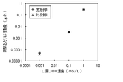
- 4 is a graph showing Li source LiOH concentration dependence of the amount of lithium transferred per hour in Examples and Comparative Examples according to the first embodiment of the present invention.
- 5 is a graph showing Li source LiOH concentration dependence of the amount of lithium transferred per hour in Examples and Comparative Examples according to the second embodiment of the present invention.
- FIG. 4 is a graph showing the amount of lithium transferred per hour from a 0.001 mol/L LiOH aqueous solution and a 1.0 mol/L LiCl aqueous solution in Examples and Comparative Examples according to the present invention.
- 1 is a schematic diagram of a lithium recovery device for explaining a conventional lithium recovery method using an electrodialysis method; FIG.
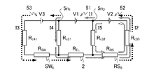
- the lithium recovery apparatus 10 includes a processing tank 1, an electrolyte membrane (lithium ion conductive electrolyte membrane) 2 that partitions the processing tank 1, and It comprises a coated first electrode 31 and a second electrode 32, a third electrode 33, a sub-electrode 41, and three power sources, a sub-power source 53, a first power source 51, and a second power source 52, connected in series.
- Lithium recovery device 10 may further comprise an agitator 72 .
- the treatment tank 1 consists of a supply tank (first tank) 11 containing a Li-containing aqueous solution SW such as seawater and a recovery tank (second tank) 13 containing a Li-recovering aqueous solution RS via an electrolyte membrane 2.
- a first electrode 31 is arranged on the supply tank 11 side, and a second electrode 32 is arranged on the recovery tank 13 side.
- the sub-electrode 41 and the third electrode 33 are provided in the supply tank 11 and the recovery tank 13, respectively, separated from the electrolyte membrane 2 .
- the first power supply 51 has a positive (+) pole connected to the first electrode 31 and a negative (-) pole connected to the second electrode 32 .
- the second power supply 52 is connected in series with the negative pole of the first power supply 51 , that is, the positive pole is connected to the second electrode 32 and the negative pole is connected to the third electrode 33 .
- the auxiliary power supply 53 is connected in series with the positive electrode of the first power supply 51 , that is, the negative electrode is connected to the first electrode 31 and the positive electrode is connected to the auxiliary electrode 41 . Therefore, the lithium recovery device 10 according to the present embodiment differs from the conventional lithium recovery device (for example, the lithium recovery device 100 shown in FIG. 11) by the electrodialysis method in that the first power source 51 (power source 151 in FIG. 11) is Both electrodes 31 and 32 (electrodes 131 and 132 in FIG.
- the treatment tank 1 is made of a material that does not undergo deterioration such as corrosion even when it comes into contact with the Li-containing aqueous solution SW and the Li-recovery aqueous solution RS (for example, lithium hydroxide (LiOH) aqueous solution) including after Li recovery.
- the processing tank 1 may have a volume corresponding to the required processing capacity, and its shape and the like are not particularly limited.
- the electrolyte membrane 2 is an electrolyte that has lithium ion conductivity, does not conduct metal ions M n + other than Li + contained in the Li-containing aqueous solution SW, and preferably does not conduct electrons e ⁇ .
- Metal ions M n+ other than Li + include, for example, K + , Na + , Mg 2+ , Ca 2+ and the like when the Li-containing aqueous solution SW is seawater. More preferably, the electrolyte membrane 2 is a ceramic electrolyte having these properties. Specifically, lithium-lanthanum-titanium oxide (La 2/3-x Li 3x TiO 3 , also called LLTO) and the like can be mentioned.
- Such an electrolyte membrane 2 has a certain proportion of lattice defects, and since the size of the lattice defect sites is small, metal ions larger in diameter than Li + do not conduct.
- the first electrode 31 and the second electrode 32 are paired to apply a voltage across both surfaces of the electrolyte membrane 2 , and the first electrode 31 is in contact with the surface of the electrolyte membrane 2 on the supply tank 11 side.
- the second electrode 32 is provided in contact with the surface of the electrolyte membrane 2 on the recovery tank 13 side.
- the first electrode 31 is also paired with a third electrode 33 described below to apply a voltage.
- the first electrode 31 and the second electrode 32 apply a voltage to a wide range of the electrolyte membrane 2, while the Li-containing aqueous solution SW or the Li-recovering aqueous solution RS is in contact with a sufficient area of the surface of the electrolyte membrane 2. It preferably has a porous structure such as a network.
- the first electrode 31 has catalytic activity and electronic conductivity for the reaction of the following formula (1) and the reaction of the following formula (3), and is formed of an electrode material that is stable even when a voltage is applied in the Li-containing aqueous solution SW. Furthermore, it is preferable to use a material that can be easily processed into the above shape.
- the second electrode 32 has catalytic activity and electronic conductivity for the reaction of the following formula (5) and the reaction of the following formula (1), and is stable even when a voltage is applied in the Li recovery aqueous solution RS including after Li recovery. It is preferable that the electrodes are made of an electrode material that is suitable for use, and that the material can be easily processed into the shape described above.
- the first electrode 31 and the second electrode 32 are preferably made of, for example, platinum (Pt) as such an electrode material.
- carbon (C) may be applied to the first electrode 31 when the Li-containing aqueous solution SW contains Cl ⁇ .
- the following formula (3) represents a reaction in which Li + in the aqueous solution (Li-containing aqueous solution SW) moves into the electrolyte membrane 2 .
- the following formula (5) represents a reaction in which Li + in the electrolyte membrane 2 moves to an aqueous solution (aqueous solution RS for recovering Li).
- the sub-electrode 41 is an electrode for forming a higher potential than the surface of the electrolyte membrane 2 in the Li-containing aqueous solution SW. Therefore, it is preferable that the sub-electrode 41 is arranged in the supply tank 11 so as not to contact the electrolyte membrane 2 and the first electrode 31 and arranged parallel to the first electrode 31 . Furthermore, in order to keep the voltage V3 of the sub-power supply 53 small, it is preferable that the sub-electrode 41 be arranged close to the first electrode 31 to the extent that short-circuiting does not occur, as will be described later. Further, the sub-electrode 41 preferably has a mesh shape or the like so as to increase the contact area with the Li-containing aqueous solution SW.
- the sub-electrode 41 has catalytic activity and electronic conductivity for the reaction of the following formula (1), and is made of an electrode material that is stable even when a voltage is applied in the Li-containing aqueous solution SW.
- the secondary electrode 41 further has catalytic activity for the oxidation reaction, for example, the reaction of the following formula (2) in the case of chloride ions (Cl ⁇ ).
- the secondary electrode 41 is preferably made of, for example, carbon (C), platinum (Pt), or carbon in which platinum fine particles are supported as a catalyst.
- the third electrode 33 is an electrode for forming a potential lower than that of the surface of the electrolyte membrane 2 in the Li recovery aqueous solution RS. Therefore, the third electrode 33 is preferably arranged in the recovery tank 13 so as not to contact the electrolyte membrane 2 and the second electrode 32 and arranged parallel to the second electrode 32 . Furthermore, in order to keep the voltage V2 of the second power supply 52 small, it is preferable that the third electrode 33 be arranged close to the second electrode 32 to the extent that short-circuiting does not occur, as will be described later. Moreover, the third electrode 33 preferably has a mesh shape or the like so as to increase the contact area with the Li recovery aqueous solution RS.
- the third electrode 33 has catalytic activity and electronic conductivity for the reaction of the following formula (4), and is formed of an electrode material that is stable even when a voltage is applied in the Li recovery aqueous solution RS including after Li recovery. Platinum (Pt) is preferred.
- the third electrode 33 can be made of carbon (C), copper (Cu), or stainless steel, which is stable at a potential lower than the potential at which the reaction of the following formula (4) occurs. It is more preferable to carry functional Pt fine particles.
- a first power supply 51, a second power supply 52, and a sub-power supply 53 are DC power supplies that apply predetermined voltages V1, V2, and V3, respectively.
- the power supplies 52 are connected in series.
- the first power source 51 has a positive electrode connected to the first electrode 31 and a negative electrode connected to the second electrode 32 .
- the second power supply 52 has a positive electrode connected to the second electrode 32 and a negative electrode connected to the third electrode 33 .
- the secondary power supply 53 has a positive electrode connected to the secondary electrode 41 and a negative electrode connected to the first electrode 31 .
- connection node 5n1 between the first power supply 51 and the sub power supply 53 is connected to the first electrode 31, and the connection node 5n2 between the first power supply 51 and the second power supply 52 is connected to the second electrode 32.
- the first power supply 51 applies a voltage V1 across the electrolyte membrane 2 to generate a potential gradient for conducting Li + in the electrolyte membrane 2 .
- the second power supply 52 applies a voltage V2 that forms a potential lower than that of the surface of the electrolyte membrane 2 to the aqueous solution RS for recovering Li, so that electrons e ⁇ are transferred from the recovery tank 13 side of the electrolyte membrane 2 to the supply tank 11 side. Suppress conduction.
- the first power source 51 and the second power source 52 which are connected in series, serve as one main power source between the Li-containing aqueous solution SW and the Li-recovering aqueous solution RS, and the voltage V1 applied between both surfaces of the electrolyte membrane 2 Also, a large voltage (V1+V2) is applied.
- the auxiliary power supply 53 applies a voltage V3 to the Li-containing aqueous solution SW to form a potential higher than that of the surface of the electrolyte membrane 2, and electrostatically charges Li + near the surface of the electrolyte membrane 2, which has a relatively low potential. While they are unevenly distributed by attraction, anions such as Cl ⁇ are kept away by electrostatic repulsion.
- the stirrer 72 is a device for circulating the Li-containing aqueous solution SW in the supply tank 11 so that the Li-containing aqueous solution SW in contact with the first electrode 31 is continuously replaced during operation, and is provided as necessary. Similarly, the stirrer 72 may circulate the Li recovery aqueous solution RS in the recovery tank 13 so that the Li recovery aqueous solution RS in contact with the second electrode 32 is continuously replaced.
- a well-known device can be applied to the stirrer 72.
- a circulation device 71 may be provided for circulating the aqueous solutions SW and RS by means of pumps between the baths 11 and 13 and circulation baths provided outside the processing bath 1 (see the modification shown in FIG. 4).
- the Li-containing aqueous solution SW is a Li source, and is an aqueous solution containing lithium ions Li + and other metal ions M n+ such as K + , Na + , and Ca 2+ .
- an aqueous solution for example, seawater, waste brine after extracting salt from seawater, underground water such as hot spring water, used lithium ion secondary batteries, etc. are crushed, roasted and dissolved in acid, and if necessary, and pH-adjusted aqueous solution.
- the Li recovery aqueous solution RS is a solution for accommodating lithium ions Li + recovered from the Li-containing aqueous solution SW.
- the Li recovery aqueous solution RS is preferably an aqueous solution that does not contain metal ions (such as Na + ) other than lithium ions Li + , and further contains anions other than OH ⁇ ,
- metal ions such as Na +
- an aqueous solution containing no halide ions is preferable, and pure water may be used.
- the Li recovery aqueous solution RS should be an aqueous solution containing Li + (lithium hydroxide (LiOH) aqueous solution) at the start of recovery (at the start of power application). preferable.
- Li + lithium hydroxide (LiOH) aqueous solution
- the lithium recovery device 10 may further include a heating device that heats the electrolyte membrane 2 via the Li-containing aqueous solution SW or the Li-recovery aqueous solution RS in order to set the electrolyte membrane 2 to a predetermined temperature.
- a heating device that heats the electrolyte membrane 2 via the Li-containing aqueous solution SW or the Li-recovery aqueous solution RS in order to set the electrolyte membrane 2 to a predetermined temperature.
- a known heater that heats a liquid can be applied to the heating device, and preferably has a temperature control function.
- the heating device is, for example, an immersion type (immersion type), and is installed by being immersed in the Li recovery aqueous solution RS in the recovery tank 13 .
- the heating portion of the heating device that is immersed in the Li-recovery aqueous solution RS is made of a material that does not deteriorate such as corrosion even when it comes into contact with the Li-recovery aqueous solution RS, like the treatment tank 1 .
- the heating device is sufficient as long as it can set the electrolyte membrane 2 to a predetermined temperature, and the Li-containing aqueous solution SW and the Li-recovering aqueous solution RS need not be uniform in liquid temperature.
- the stirrer 72 may be provided depending on the volume of the processing tank 1 and the like.
- the temperature of the electrolyte membrane 2 may be above the freezing point and below the boiling point of the aqueous solutions SW and RS, and is preferably high as described later.
- the lithium recovery apparatus 10 may further include a liquid level sensor or the like to sense fluctuations in the amounts of the Li-containing aqueous solution SW and the Li-recovery aqueous solution RS during operation.
- a liquid level sensor or the like to sense fluctuations in the amounts of the Li-containing aqueous solution SW and the Li-recovery aqueous solution RS during operation.
- CO 2 carbon dioxide
- Li 2 CO 3 lithium carbonate
- the lithium recovery device 10 is preferably configured so that the Li recovery aqueous solution RS is not exposed to the atmosphere.
- the lithium recovery device 10 is designed so as not to fill the interior with gases such as O 2 and H 2 generated during operation (due to the reactions of formulas (1), (4), and (2)) and Cl 2 .
- gases such as O 2 and H 2 generated during operation (due to the reactions of formulas (1), (4), and (2)) and Cl 2 .
- the lithium recovery apparatus 10 discharges the gas generated from the aqueous solutions SW and RS to the outside of the processing tank 1 and prevents the outside air from flowing into the supply tank 11 and the recovery tank 13 of the processing tank 1, for example.
- a check valve is preferably provided.
- Lithium recovery method A lithium recovery method according to a first embodiment of the present invention will be described with reference to FIGS. 2 and 3.
- FIG. The lithium recovery method according to the present embodiment is performed as follows by using the lithium recovery device 10 according to the first embodiment shown in FIG. 2, the stirrer 72 is omitted.
- the sub power supply 53, first power supply 51, and second power supply 52 connected in series can be regarded as one power supply (referred to as power supply 50).
- the first power supply 51 and the second power supply 52 can be regarded as one power supply (referred to as main power supplies 51-52).
- the power supply 50 applies a positive voltage (V3+V1+V2) to the sub-electrode 41 with respect to the third electrode 33 .
- the main power supply 51-52 applies a positive voltage (V1+V2) to the first electrode 31 with respect to the third electrode 33. Then, the following reactions occur in the Li-containing aqueous solution SW in the supply tank 11 .
- hydroxide ions (OH ⁇ ) in the Li-containing aqueous solution SW cause the reaction of the following formula (1) to release electrons e ⁇ to form water (H 2 O) and oxygen (O 2 ) are generated, and electrons e ⁇ are emitted to the sub-electrode 41 and the first electrode 31 .
- the Li-containing aqueous solution SW contains halide ions such as chloride ions (Cl ⁇ )
- the reaction of the following formula (2) further occurs to release electrons e ⁇ and generate chlorine (Cl 2 ).
- a gas corresponding to the type of anions contained in the Li-containing aqueous solution SW is generated.
- Li + in the Li-containing aqueous solution SW moves into the electrolyte membrane 2 in order to maintain the charge balance. occurs on the surface of the electrolyte membrane 2 , that is, in the vicinity of the first electrode 31 .
- the application of the voltage V3 by the sub-power supply 53 forms a potential gradient in which the potential of the sub-electrode 41 is higher than that of the surface of the electrolyte membrane 2 (first electrode 31). Therefore, OH - and Cl - are attracted to the sub-electrode 41 by electrostatic attraction. Further, since the potential of the sub-electrode 41 is sufficiently high, Cl ⁇ is easily oxidized in the vicinity thereof, and the reaction of formula (2) tends to occur at high speed. Therefore, in the vicinity of the sub-electrode 41, Cl ⁇ decreases due to the reaction of formula (2). Then, Cl ⁇ is further attracted to the sub-electrode 41 by electrostatic attraction. As a result, in the vicinity of the first electrode 31, which has a lower potential than the sub-electrode 41, the Cl.sup.- concentration becomes relatively low, and the reaction of formula (1) mainly occurs.
- the following reactions occur.
- the voltage (V1+V2) is applied by the main power supply 51-52, and the H 2 O in the Li recovery aqueous solution RS is supplied with electrons e ⁇ , whereby the reaction of the following formula (4) to generate hydrogen (H 2 ) and OH ⁇ .
- H + decreases in the vicinity of the third electrode 33, so Li + in the electrolyte membrane 2 moves to the Li recovery aqueous solution RS on the surface of the electrolyte membrane 2, that is, in the vicinity of the second electrode 32.
- the reaction of (5) is produced.
- the second power supply 52 applies a positive voltage V2 of a predetermined magnitude based on the voltages V1 and V3 to the second electrode 32 and the third electrode 33 . Then, in the vicinity of the second electrode 32, OH - in the Li recovery aqueous solution RS undergoes the reaction of the following formula (1), electrons e - are emitted to the second electrode 32, and H 2 O and O 2 are generated. generate. As a result, in the vicinity of the second electrode 32, a charge imbalance occurs due to excess cations due to the reaction of the following formula (1) and the reaction of the following formula (5).
- the electrolyte membrane 2 has a potential gradient in which the potential of the surface on the opposite side (the recovery tank 13 side) is low. It jumps (hops) to a nearby lattice defect site on the deep side of the electrolyte membrane 2 .
- Li + repeatedly migrates from the lattice defect site of the electrolyte membrane 2 to the lattice defect site in the vicinity thereof, and finally, as the reaction of formula (5), the lattice defect site on the surface of the recovery tank 13 is to the Li recovering aqueous solution RS.
- Li + at the lattice defect sites on the surface of the electrolyte membrane 2 on the side of the supply tank 11 moves to the deep part of the electrolyte membrane 2 .
- the application of the voltage V3 by the auxiliary power supply 53 forms a potential gradient in the Li-containing aqueous solution SW, so that the Li-containing aqueous solution SW converts Cl ⁇ Even if it contains Cl ⁇ , the concentration of Cl ⁇ in the vicinity of the electrolyte membrane 2 is relatively low. Therefore, less Cl ⁇ is adsorbed to the surface of the electrolyte membrane 2, and inhibition of the reaction of formula (3) is suppressed.
- Li + migration between lattice defect sites in 2 is facilitated.
- the Li + movement in the electrolyte membrane 2 becomes faster as the Li + concentration gradient in the electrolyte membrane 2 increases. Therefore, the stronger the electric field generated in the Li-containing aqueous solution SW by the voltage V3 of the secondary power supply 53, and the stronger the electric field generated in the Li-recovering aqueous solution RS by the voltage V2 of the second power supply 52, the reaction of formula (3) and the reaction of formula (5) becomes faster, and Li + in the Li-containing aqueous solution SW can be moved at high speed into the electrolyte membrane 2 and further to the Li-recovering aqueous solution RS for recovery.
- the stronger the electric field generated in the Li-containing aqueous solution SW the faster the reaction of the formula (3) can be performed even if the Li-containing aqueous solution SW has a low Li + concentration.
- the stronger the electric field generated in the Li-containing aqueous solution SW the less likely the reaction of formula (3) is inhibited by Cl.sup.- .
- the movement of Li + in the electrolyte membrane 2 also becomes faster as the potential gradient in the electrolyte membrane 2 increases, that is, as the voltage V1 of the first power supply 51 increases.
- the reaction of 5) becomes faster, and Li + in the electrolyte membrane 2 can be moved to the aqueous solution RS for recovering Li.
- the reaction of the following formula (4) occurs in the vicinity of the first electrode 31 in the Li-containing aqueous solution SW, causing H 2 will occur. Since this reaction receives electrons e ⁇ , the movement of electrons e ⁇ (see FIG. 2) in the vicinity of the first electrode 31 is opposite to the reaction of the following formula (1).
- the electrolyte membrane 2 When the vicinity of the first electrode 31, i.e., the surface of the electrolyte membrane 2 on the side of the supply tank 11, reaches the generation potential of H2 , the electrolyte membrane 2 is formed regardless of the magnitude of the voltage V1 applied across both surfaces of the electrolyte membrane 2. A potential at which some of the metal ions are reduced (for example, if the electrolyte membrane 2 is LLTO, Ti 4+ +e ⁇ ⁇ Ti 3+ ) is reached, and the electrolyte membrane 2 develops electron transferability. Then, the electrons e ⁇ conducting through the electrolyte membrane 2 generate Joule heat, so the energy efficiency in moving Li + sharply decreases.
- the voltage V3 should be less than the voltage at which electrolysis of water occurs, and preferably greater within this range. Note that the voltage at which water electrolysis occurs is actually determined by the theoretical voltage ( 1.229 V, 25° C.). Furthermore, in the present embodiment, even if the voltage V3 is the above value or more, if the voltage V2 is larger than the voltage V3 by a certain amount or more, the potential of the surface of the electrolyte membrane 2 facing the supply tank 11 is less than the H 2 generation potential. voltage V3 can be set up to a higher value because the electrolysis of water does not occur.
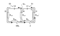
- the lithium recovery apparatus 10 includes a second power supply 52, a first power supply 51, a secondary power supply 53, a Li-containing aqueous solution SW E , an electrolyte membrane 2, an aqueous Li recovery solution RS E , a second It includes a closed circuit in which two power sources 52 are connected in a circular fashion.
- the positive electrode of the first power supply 51 and the negative electrode of the sub power supply 53 (connection node 5n 1 ) are connected to the electrolyte membrane 2 and the Li-containing aqueous solution SW E via the first electrode 31, respectively.
- the negative electrode of the first power source 51 and the positive electrode (connection node 5n 2 ) of the second power source 52 are connected via the second electrode 32 to the electrolyte membrane 2 and the aqueous Li recovery solution RSE , respectively. Therefore, in the lithium recovery device 10, current can flow either from the connection node 5n 1 to the electrolyte membrane 2 or from the Li-containing aqueous solution S E or the electrolyte membrane 2 to the connection node 5n 1 .
- connection node 5n2 the resistance between the first electrode 31 and the second electrode 32, the movement resistance of Li +
- R EL the resistance of the Li-containing aqueous solution S E (the resistance between the first electrode 31 and the sub-electrode 41)
- R SW the resistance of the Li recovery aqueous solution RS E (resistance between the second electrode 32 and the third electrode 33 )
- the lithium recovery device 10 has a reaction resistance R c41 due to the reaction (O 2 generation) of formula (1) and the reaction (Cl 2 generation) of formula (2) at the sub electrode 41 , and the reaction resistance R c41 at the first electrode 31 of formula (1) and the reaction resistance R c31 due to the reaction of formula (2).
- the lithium recovery apparatus 10 includes, as a second circuit, a closed circuit in which the second power source 52, the first power source 51, the electrolyte membrane 2, the Li recovery aqueous solution RS E , and the second power source 52 are connected in a ring in this order. . As shown in FIG.
- currents I4, I1 and I2 are supplied to this closed circuit as indicated by gray arrows by a first power supply 51 and a second power supply 52 (main power supplies 51-52) connected in series. flow.
- a current branching from the current I1 (from the connection node 5n1 ) and flowing toward the electrolyte membrane 2 via the first electrode 31 is denoted by I4.
- the lithium recovery apparatus 10 connects ammeters (not shown) in series to the first power supply 51 and the auxiliary power supply 53, respectively, and applies voltages V1 and V3 while measuring the currents I1 and I3. Just do it.
- the lower the resistance R sw between the first electrode 31 and the sub-electrode 41 and the reaction resistance R c41 at the sub-electrode 41 the stronger the electric field generated in the Li-containing aqueous solution SW even if the voltage V3 is small, and the effect is high. is obtained.
- the reaction resistance R c41 decreases as the area of the sub-electrode 41 immersed in the Li-containing aqueous solution SW increases and as the catalytic activity of the sub-electrode 41 for the reaction of formula (1) increases.
- the resistance R SW decreases as the areas of the first electrode 31 and the sub-electrode 41 immersed in the Li-containing aqueous solution SW increase and as the distance between them decreases.
- the higher the electronic conductivity of the Li-containing aqueous solution SW the lower the resistance R SW .
- the reaction of formula (1) or further the reaction of formula (2) at the first electrode 31 such that the current I4 flows from the positive electrode (connection node 5n 1 ) of the first power supply 51 to the first electrode 31, and the secondary electrode
- the total reaction amount of the reaction of formula (1) and the reaction of formula (2) at 41 is directly related to the amount of Li + moving through the electrolyte membrane 2, and Li + corresponding to the current amount of (I3 + I4) It moves across the electrolyte membrane 2 .
- the total current amount of (I3+I4) that is, the current I1 is as large as possible.
- I1>I3 including a margin so that I1 ⁇ I3 does not occur.
- I1>I3 I4>0
- O 2 is generated even at the first electrode 31 .
- the voltage V1 can be set to a sufficient magnitude as described below.
- the voltage V1 that is, the potential difference between both surfaces of the electrolyte membrane 2 causes some of the metal ions constituting the electrolyte membrane 2 to be reduced (for example, if the electrolyte membrane 2 is LLTO, Ti 4+ +e ⁇ ⁇ Ti 3+ ) voltage (referred to as electrolyte reduction voltage as appropriate)
- the electrolyte membrane 2 can conduct electrons e ⁇ from the collection tank 13 side to the supply tank 11 side (see Patent Document 2). Therefore, even if the voltage V1 is further increased, the amount of movement of Li + does not increase by the amount of the increase in the voltage V1, and the energy efficiency decreases.
- a second power supply 52 connected between the second electrode 32 and the third electrode 33 applies a voltage V2 to create an appropriate potential difference with the second electrode 32 being positive. Then, the electrons e ⁇ supplied from the third electrode 33 to the Li recovery aqueous solution RS move from the second electrode 32 on the surface of the electrolyte membrane 2 to the positive electrode of the second power supply 52 , and the potential of the second electrode 32 becomes O 2 It is maintained as high as the generated potential. Since the O 2 generation potential is higher than the reduction potential of the metal ions forming the electrolyte membrane 2, the electrolyte membrane 2 does not conduct electrons e ⁇ regardless of the potential difference between the two surfaces.
- the voltage V1 can be set to a voltage higher than the electrolyte reduction voltage of the electrolyte membrane 2 .
- the voltage V2 when such a large voltage V1 is applied without applying the voltage V2, electrons e ⁇ are taken in from the negative electrode side (recovery tank 13 side) of the electrolyte membrane 2 to reduce metal ions. .
- Such a phenomenon is likely to occur particularly with transition metal ions.
- the application of the voltage V2 does not allow the electrolyte membrane 2 to reach the reduction potential of the metal ions, and the electrolyte membrane 2 does not transfer electrons e ⁇ .
- the lithium recovery apparatus 10 includes, as a third circuit, a closed circuit composed of a second power supply 52 and an aqueous Li recovering solution RSE .
- I2 flows.
- a current I5 branches from the current I2 and flows to the second electrode 32 (from the connection node 5n2 ).
- the lithium recovery device 10 is configured as follows so that the current I5 may or may not flow in such a direction (does not flow in the opposite direction), that is, I5 ⁇ 0.
- R EL is the resistance of the electrolyte membrane 2 (the resistance between the first electrode 31 and the second electrode 32, the movement resistance of Li + ); ) is represented as R RS .
- the lithium recovery device 10 has a reaction resistance R c33 due to the reaction (H 2 generation) of the formula (4) at the third electrode 33 and a reaction resistance R c33 due to the reaction (O 2 generation) of the formula (1) at the second electrode 32 Further includes R c32 .
- the first circuit is represented by the following equation (6)
- the second circuit is represented by the following equation (7)
- the third circuit is represented by the following equation (8).
- the resistance of the electrodes 31, 32, 41, 33 and wiring is ignored.
- the following formula (9) is obtained from the formulas (6) and (7), and the following formula (10) is obtained from the formulas (7) and (8).
- the current I1 is represented by the following formula (11) from the following formula (10).
- the current I2 is represented by the following formula (12) from the formula (8).
- the current I3 is represented by the following formula (13) from the following formula (9).
- the following equation (14) should be established. Solving the equation (14) yields the equation (15). Also, substituting the following equation (12) for I2 in the following equation (11) and the following equation (13) for I3, respectively, and solving for I1 yields the following equation (16). Substituting the formula (16) into the formula (15) yields the formula (17).
- the lithium recovery apparatus 10 connects ammeters (not shown) in series to the first power source 51 and the second power source 52, respectively, and applies voltages V1 and V2 while measuring the currents I1 and I2. do it.
- the lower the resistance R RS between the second electrode 32 and the third electrode 33 and the reaction resistance R c33 at the third electrode 33 the higher the effect can be obtained even if the voltage V2 is small.
- the reaction resistance R c33 decreases as the area of the third electrode 33 immersed in the Li recovery aqueous solution RS increases and as the catalytic activity of the third electrode 33 for the reaction of formula (4) increases.
- the resistance R RS decreases as the areas of the second electrode 32 and the third electrode 33 immersed in the Li recovering aqueous solution RS become larger and the distance between them becomes shorter. Also, the resistance R RS is lower as the electronic conductivity of the aqueous solution RS for Li recovery is higher.
- reaction amount of the reaction of formula (1) occurring at the second electrode 32 that is, the magnitude of the current I5 ( ⁇ 0) is not directly related to the amount of movement of Li + .
- the voltage V2 is insufficient with respect to the voltages V1 and V3 and the equation (17) does not hold, then I5 ⁇ 0, current flows from the second electrode 32 to the negative electrode of the auxiliary power supply 53, and the second electrode 32 also has the equation Reaction (4) comes to occur.
- the voltage V1 is represented by the following equation (18).
- R c32 ′ is the reaction resistance due to the reaction (H 2 generation) of formula (4) at the second electrode 32 .
- ⁇ R c32 ′) is the reduction potential of the metal ions constituting the electrolyte membrane 2 (in the case of Ti, , Ti 4+ ⁇ Ti 3+ ; ⁇ 0.488 V vs. SHE).
- the larger the voltage V2 the larger the Li + concentration gradient in the electrolyte membrane 2 and the faster the movement of Li + in the electrolyte membrane 2 .
- the current I5 increases, and O 2 is generated near the second electrode 32 ( (1) and generation of H 2 (reaction (4)) in the vicinity of the third electrode 33 increase more than the amount of moving Li + , and the energy efficiency decreases.
- the voltage V2 satisfies I1>I2, as described above, if the difference
- the resistance R RS decreases due to an increase in the Li + concentration of the Li recovery aqueous solution RS
- a margin of It is preferable to set the voltage V2 so that I1 ⁇ I2.
- the liquid amounts of the Li-containing aqueous solution SW and the Li-recovery aqueous solution RS decrease. 11 is preferred.
- the Li recovery aqueous solution RS it is preferable to add water (H 2 O) or the like to the recovery tank 13 periodically or all the time.
- the liquid levels in the supply tank 11 and the recovery tank 13 are uniform during operation.
- Lithium carbonate (Li 2 CO 3 ) is produced by, for example, carbon dioxide (CO 2 ) bubbling in the aqueous solution RS for recovering Li after completion of the operation, for example, after concentrating Li by evaporating water if necessary. Li can be recovered by separating and depositing Li. Alternatively, after lithium carbonate is produced, lithium hydroxide (LiOH) is produced in a supersaturated state by cooling or by evaporating water, and Li can be recovered by depositing it.
- carbon dioxide CO 2
- Li lithium hydroxide
- the auxiliary power supply 53 is connected in series with the positive electrode of the first power supply 51 that applies the voltage V1 between both surfaces of the electrolyte membrane 2.
- the secondary electrode 41 of Li + is unevenly distributed in the vicinity of the electrolyte membrane 2 while Cl ⁇ is kept away from the electrolyte membrane 2 .
- inhibition of dissolution of Li + in the Li-containing aqueous solution SW into the electrolyte membrane 2 due to adsorption of Cl ⁇ to the surface of the electrolyte membrane 2 is suppressed. Therefore, Li + can be efficiently recovered by using a Li source such as seawater containing Cl ⁇ at a high concentration as the Li-containing aqueous solution SW.
- the Li-containing aqueous solution SW has a relatively high Li + concentration in the vicinity of the electrolyte membrane 2 , a concentration gradient of Li + is efficiently formed in the electrolyte membrane 2 , and movement of Li + in the electrolyte membrane 2 is suppressed. It can be faster. Such an effect becomes more remarkable when the Li-containing aqueous solution SW has a low Li + concentration.
- a second power supply 52 is provided which is connected in series to the negative electrode of the electrolyte membrane 2.
- the third electrode 33 having a potential lower than that of the surface of the electrolyte membrane 2 and setting this potential difference, that is, the voltage V2 of the second power supply 52 corresponding to the voltage V1
- the electrolyte membrane 2 reaches the reduction potential of the metal ion. Even if a large potential difference is generated between the two surfaces, the electron e ⁇ is difficult to conduct. As a result, the recovery rate of Li + can be increased corresponding to the potential gradient in the electrolyte membrane 2 .
- the potential gradient is efficiently formed in the electrolyte membrane 2 by the first power source 51 , and It is possible to increase the moving speed of Li + at . Furthermore, when the voltage V2 of the second power supply 52 is increased in accordance with the increase of the voltage V1 of the first power supply 51, the concentration gradient of Li + is formed in the electrolyte membrane 2 more efficiently, and the Li + concentration in the electrolyte membrane 2 movement can be further accelerated.
- the movement of Li + in the electrolyte membrane 2 becomes faster as the temperature becomes higher as well as the voltage V1. Therefore, it is preferable that the temperature of the electrolyte membrane 2 is high. Also, the resistances R EL , R SW , R RS of the electrolyte membrane 2 and the aqueous solutions SW, RS and the reaction resistances at the electrodes 31 , 32 , 41 , 33 are lower as the temperature is higher.
- the applicable temperature range is from the freezing point to the boiling point of the aqueous solutions SW and RS, preferably 20° C. or higher.
- the Li source containing chloride ions is in direct contact with the surface of the electrolyte membrane on the supply tank side. Therefore, even if the chloride ions are kept away by the electrostatic repulsion due to the voltage application from the auxiliary power source, the catalytic activity is impaired to some extent in long-term operation.
- the higher the pH of the aqueous solution on the Li + supply side of the electrolyte membrane with respect to the recovery side aqueous solution the higher the Li + mobility. For example, when seawater is used as the Li source, the seawater is weakly alkaline.
- the aqueous solution on the recovery side changes from pure water before the start to an aqueous LiOH solution as the process progresses, and the concentration increases and the pH also increases. It will be higher with respect to the supply side and the Li + mobility will decrease.
- the following configuration was adopted.
- a lithium recovery device and a lithium recovery method according to modifications of the first embodiment of the present invention will be described with reference to FIGS. 4 and 5.
- a lithium recovery apparatus 10A includes a processing tank 1, an electrolyte membrane (lithium ion conductive electrolyte membrane) 2 that partitions the processing tank 1, and an ion exchange membrane 62. , a first electrode 31 and a second electrode 32 coated on each side of the electrolyte membrane 2, a third electrode 33, a sub-electrode 41, and three power sources 53, 51, 52 connected in series.
- the lithium recovery device 10A may further include a circulation device (circulation means) 71 and an agitator 72 .
- the treatment tank 1 includes a supply tank (first tank) 11 containing a Li-containing aqueous solution SW such as seawater and an intermediate tank 12 containing a Li-containing aqueous solution AS in one direction by an ion exchange membrane 62 and an electrolyte membrane 2 . , and a recovery tank (second tank) 13 containing an aqueous solution RS for Li recovery.
- the ion exchange membrane 62 separates the supply tank 11 and the intermediate tank 12
- the electrolyte membrane 2 separates the intermediate tank 12 and the recovery tank 13 .
- a sub-electrode 41 is provided in the supply tank 11 .
- the third electrode 33 is provided inside the recovery tank 13 so as to be separated from the electrolyte membrane 2 . Therefore, the lithium recovery device 10A according to this modification differs from the lithium recovery device 10 according to the embodiment shown in FIG. is added, and the supply tank 11 is further partitioned into the supply tank 11 and the intermediate tank 12 by the ion exchange membrane 62 .
- the ion exchange membrane 62 conducts cations containing at least Li + .
- the ion exchange membrane 62 can prevent the Li-containing aqueous solution AS in the intermediate tank 12 from containing halide ions such as Cl ⁇ .
- the ion exchange membrane 62 is a cation exchange membrane that allows cations to pass through and anions to be blocked, and a monovalent cation selective permeation ion exchange membrane that allows only monovalent cations such as Li + , K + , and Na + to pass through.
- Membranes, bipolar monovalent ion permselective ion exchange membranes that allow monovalent ions to permeate, and the like can be applied.
- Known ion-exchange membranes can be applied.
- SELEMION registered trademark
- NOSEPTA CIMS manufactured by Astom Co., Ltd.
- the lithium recovery device 10A it is preferable that the distance between the sub-electrode 41 and the first electrode 31 is short as in the above-described embodiment. It is preferable that the intermediate tank 12 is arranged so as to be short.
- the circulation device 71 includes, for example, a pump and a filter for removing dust and the like.
- the Li-containing aqueous solution SW is seawater, hot spring water, or the like, it is preferable to apply the voltage while circulating the Li-containing aqueous solution SW from these supply sources into the supply tank 11 .
- the Li + concentration of the Li-containing aqueous solution SW is maintained substantially constant even if the recovery of Li + progresses, and even with a low-concentration Li aqueous solution, the Li recovery rate does not easily decrease, and the recovery of Li is difficult for a long period of time. Continuous operation is possible.
- the Li-containing aqueous solution SW in the supply tank 11 may be exchanged in the circulation device 71 every operation for a certain period of time.
- the lithium recovery apparatus 10A may have a structure in which the supply tank 11 is open to the outside (for example, into the sea) through a filter or the like.
- the Li-containing aqueous solution AS is an aqueous solution obtained by removing anions other than OH ⁇ , such as Cl ⁇ , from the Li-containing aqueous solution SW stored in the supply tank 11 .
- the Li-containing aqueous solution AS can be pure water in the same manner as the Li-recovering aqueous solution RS, and is preferably an aqueous solution containing Li + (LiOH aqueous solution). .
- the auxiliary power supply 53 applies the voltage V3 to the Li-containing aqueous solution AS in contact with the surface of the electrolyte membrane 2 on the supply side, as in the above-described embodiment, to form a higher potential than the surface of the electrolyte membrane 2, Li + is unevenly distributed near the surface of the electrolyte membrane 2 by electrostatic attraction.
- the Li-containing aqueous solution SW on the supply tank 11 side generates a high potential difference between both surfaces of the ion-exchange membrane 62, that is, between the Li-containing aqueous solution SW and the Li-containing aqueous solution AS, so that the Li-containing aqueous solution SW
- the cations containing Li + in the solution are transferred to the Li-containing aqueous solution AS.
- the intermediate tank 12 may also be provided with a circulation device 71 or a stirrer 72 .
- the circulation device 71 for circulating the Li-containing aqueous solution AS may include a sedimentation tank for precipitating cations other than Li + in the Li-containing aqueous solution AS, and a filter for preventing the precipitate from returning to the intermediate tank 12. .
- a lithium recovery method according to a modification of the first embodiment of the present invention will be described with reference to FIG. 5, the circulation device 71 and the stirrer 72 are omitted.
- the lithium recovery method according to this modification can be performed in the same manner as the lithium recovery method according to the first embodiment by using a lithium recovery device 10A according to the modification of the first embodiment shown in FIG.
- secondary power supply 53 applies voltage V3, so that cations such as Li + in Li-containing aqueous solution SW permeate ion-exchange membrane 62 and move to Li-containing aqueous solution AS. Furthermore, as described in the above embodiment, Li + is attracted to the surface of the electrolyte membrane 2 (first electrode 31) by electrostatic attraction in the Li-containing aqueous solution AS due to the potential gradient due to the voltage V3. Reactions caused by the application of voltages V1, V2, and V3 are as described in the above embodiment.
- the Li-containing aqueous solution AS contains Li + , K + , Na + and the like. Only monovalent cations migrate, and divalent and trivalent cations such as Ca 2+ do not migrate. Therefore, the amount of precipitate in the Li-containing aqueous solution AS that contacts the supply side surface of the electrolyte membrane 2 can be reduced, and the movement of Li + from the Li-containing aqueous solution AS to the Li-recovering aqueous solution RS is not hindered.
- the resistance R SW of the Li-containing aqueous solution SW E is the sum of the resistances of the Li-containing aqueous solutions SW and AS between the first electrode 31 and the sub-electrode 41 and the ion exchange membrane 62 .
- the Li-containing aqueous solution AS is pure water (not containing Li + ) or a low-concentration LiOH aqueous solution at the start of recovery, first, only the auxiliary power supply 53 is operated to add Li + to the Li-containing aqueous solution AS. It is preferable to further operate the first power source 51 and the second power source 52 after moving and reaching a predetermined concentration.
- anions such as chloride ions are shielded from the Li-containing aqueous solution in the supply tank, anions are not contained in the aqueous solution contacting the supply side surface of the electrolyte membrane. This makes it possible to make the first electrode provided on this surface of the electrolyte membrane more difficult to deteriorate.
- the aqueous solution in contact with the supply side surface of the electrolyte membrane can be made to have a high pH, and Li + migration with respect to the applied voltage The higher the temperature, the higher the energy efficiency.
- the lithium recovery apparatus includes two or more ion exchange membranes that conduct cations including Li + , the processing tank is divided into four or more, and two or more are provided between the supply tank and the recovery tank at both ends. An intermediate tank may be provided. Such a lithium recovery device is constructed such that all ion exchange membranes are sandwiched between the first electrode and the secondary electrode in the feed tank. By providing a plurality of ion exchange membranes, anions such as chloride ions are more shielded from the Li-containing aqueous solution in the supply tank, so that more anions are contained in the aqueous solution in contact with the supply side surface of the electrolyte membrane.
- monovalent cation permselective ion exchange membranes and bipolar type monovalent ion permselective ion exchange membranes have sufficient resistance to strong alkalinity. Many don't have it.
- the aqueous solution obtained by removing anions from the Li-containing aqueous solution SW tends to be strongly alkaline if the concentration of cations is high.
- Li + is removed from the Li-containing aqueous solution AS by moving it to the Li-recovering aqueous solution RS or by precipitating monovalent cations other than Li + .
- the lithium recovery device can be equipped with a combination of a cation exchange membrane that conducts cations including multivalent ions and a monovalent ion selective permeable ion exchange membrane.
- increasing the number of ion-exchange membranes increases the resistance between the first electrode and the sub-electrode, making it difficult to generate a strong electric field if the voltage applied by the sub-power supply is less than the voltage at which electrolysis of water occurs. is. Therefore, only some of the plurality of ion-exchange membranes are arranged between the first electrode connected to the sub-power supply and the sub-electrode, and voltage is applied to the other ion-exchange membranes by the additional sub-power supply. preferably.
- a lithium recovery apparatus 10B includes a processing tank 1, an electrolyte membrane (lithium ion conductive electrolyte membrane) 2 partitioning the processing tank 1, and Ion exchange membranes 61 and 62, a first electrode 31 and a second electrode 32 coated on each side of the electrolyte membrane 2, a third electrode 33, sub-electrodes 41, 42 and 43, three power sources 53 and 51 connected in series, 52 and a secondary power supply 54 .
- the lithium recovery device 10B may further include a circulation device 71 and a stirrer 72 as necessary (see FIGS. 1 and 4).
- the processing tank 1 is divided in one direction by the two ion exchange membranes 61 and 62 and the electrolyte membrane 2 into a supply tank (first tank) 11 containing the Li-containing aqueous solution SW and an intermediate tank containing the Li-containing aqueous solution AS'. It is partitioned into four tanks 12a, an intermediate tank 12b containing the Li-containing aqueous solution AS, and a recovery tank (second tank) 13 containing the Li-recovering aqueous solution RS. Specifically, the ion exchange membrane 61 partitions the supply tank 11 and the intermediate tank 12a, the ion exchange membrane 62 partitions the intermediate tank 12a and the intermediate tank 12b, and the electrolyte membrane 2 partitions the intermediate tank 12b and the recovery tank 13.
- the third electrode 33 is provided in the recovery tank 13 so as to be separated from the electrolyte membrane 2 .
- the sub-electrodes 41 and 43 are spaced apart from each other in the intermediate tank 12 a , the sub-electrode 41 facing the ion-exchange membrane 62 and the sub-electrode 43 facing the ion-exchange membrane 61 .
- a sub-electrode 42 is provided in the supply tank 11 .
- the secondary power supply 54 has a positive electrode connected to the secondary electrode 42 and a negative electrode connected to the secondary electrode 43 . Therefore, the lithium recovery device 10B according to the present modification is different from the lithium recovery device 10A according to the modification shown in FIG. It has a configuration in which a sub-power source 54 for applying a voltage between both surfaces of the film 61 and sub-electrodes 42 and 43 connected to the sub-power source 54 are added.
- the ion exchange membrane 61 is provided on the Li + supply side with respect to the electrolyte membrane 2 and conducts cations containing at least Li + .
- the same ion exchange membrane as the ion exchange membrane 62 can be applied to the ion exchange membrane 61 .
- a cation exchange membrane that conducts cations including multivalent ions is applied to one of the ion exchange membranes 61 and 62, and a monovalent cation permselective ion exchange membrane or a bipolar type monovalent ion permselective ion exchange membrane is applied to the other.
- An ion exchange membrane may be applied.
- the sub-electrode 42 and the sub-electrode 43 are electrodes for connecting to the sub-power supply 54 and applying a voltage between both surfaces of the ion exchange membrane 61 to generate a high potential difference on the supply tank 11 side.
- the sub-electrode 42 and the sub-electrode 43 are arranged in the supply tank 11 and the intermediate tank 12a, respectively, facing the ion-exchange membrane 61 .
- the sub-electrodes 42 and 43 are preferably arranged parallel to each other.
- the sub-electrodes 42 and 43 preferably have a mesh shape or the like through which the aqueous solutions pass so that the aqueous solutions SW and AS' in contact with the surfaces of the ion exchange membranes 61 in the tanks 11 and 12a are continuously replaced.
- the sub-electrode 41 is made of an electrode material that is stable even when a voltage is applied in the Li-containing aqueous solution AS' including after Li recovery, and the sub-electrode 43 is formed in the same manner.
- the sub-electrode 42 is made of an electrode material that is stable even when a voltage is applied in the Li-containing aqueous solution SW.
- the sub-electrode 43 is spaced apart from the sub-electrode 41 provided in the same intermediate tank 12a. It is designed to have a sufficient length in the partition direction (horizontal direction in FIG. 6).
- the auxiliary power supply 54 applies a voltage V4 between both surfaces of the ion-exchange membrane 61, that is, between the Li-containing aqueous solution SW and the Li-containing aqueous solution AS', which causes the Li-containing aqueous solution SW on the supply tank 11 side to generate a high potential difference, The cations containing Li + in the Li-containing aqueous solution SW are moved to the Li-containing aqueous solution AS'.
- the sub-power supply 54 is a DC power supply like the sub-power supply 53, and has a positive electrode connected to the sub-electrode 42 in the supply tank 11 and a negative electrode connected to the sub-electrode 43 in the intermediate tank 12a.
- the Li-containing aqueous solution AS′ is an aqueous solution obtained by removing anions other than OH ⁇ , such as Cl ⁇ , from the Li-containing aqueous solution SW stored in the supply tank 11 .
- the Li-containing aqueous solution AS' can be pure water in the same manner as the Li-containing aqueous solution AS and the Li - recovering aqueous solution RS. ) is preferred.
- the acid to be added to the Li-containing aqueous solution AS' should be one that does not precipitate Li + , and preferably nitric acid, sulfuric acid, or the like, avoiding Cl - , which tends to generate gas by oxidation reaction and impairs the catalytic activity of the platinum electrode. Even if the Li-containing aqueous solution AS′ contains anions such as NO 3 ⁇ , these anions are not contained in the Li-containing aqueous solution AS in contact with the electrolyte membrane 2 because they are shielded by the ion exchange membrane 62 .
- the Li-containing aqueous solution AS containing no anions other than OH ⁇ may become strongly alkaline, it is preferable to use a cation exchange membrane having high alkali resistance as the ion exchange membrane 62 .
- the Li-containing aqueous solution AS in contact with the surface of the electrolyte membrane 2 on the supply tank 11 side has a sufficiently high Li + concentration, and Li can be efficiently recovered with a high Li + mobility. .
- the voltage V4 is greater than a certain value, the reaction of the following formula (1) occurs in the vicinity of the sub-electrode 42 to generate O 2 , and if the Li-containing aqueous solution SW contains Cl ⁇ , A reaction of the following formula (2) occurs to generate Cl 2 . At the same time, the reaction of the following formula (4) occurs in the vicinity of the sub-electrode 43 to generate H 2 . Since the energy efficiency decreases as the reaction amount of these reactions increases, it is preferable that the voltage V4 is small within a range in which the Li + mobility does not limit the rate.
- the electric field generated by the application of the voltage V4 increases as the distance between the sub-electrodes 42 and 43 and the ion exchange membrane 61 decreases and as the electronic conductivity of the Li-containing aqueous solutions SW and AS' increases. become stronger against Therefore, by arranging the sub-electrodes 42 and 43 and by setting the Li-containing aqueous solution AS' to an aqueous solution containing ions at the start of operation, the amount of movement of cations such as Li + per time with respect to the voltage V4 is can do a lot.
- the auxiliary power sources 53 and 54 are operated to convert the Li-containing aqueous solution AS to Li + is moved to reach a predetermined concentration, and then the first power source 51 and the second power source 52 are preferably further operated.
- the lithium recovery device 10B it is possible to individually set the voltage to be applied between both surfaces of the ion exchange membrane 61 and between both surfaces of the ion exchange membrane 62 . Therefore, it is easy to individually control the pH of each of the Li-containing aqueous solutions AS' and AS during operation.
- a cation exchange membrane that conducts cations including multivalent ions is applied to the ion exchange membrane 61, and a monovalent ion selective permeable ion exchange membrane is applied to the ion exchange membrane 62.
- monovalent ions other than Li + can be recovered from the Li-containing aqueous solution AS in the intermediate tank 12b.
- the lithium recovery device 10B includes three ion exchange membranes arranged in the order of a cation exchange membrane, a monovalent ion permselective ion exchange membrane, and a cation exchange membrane, and has three tanks. An intermediate tank may be provided.
- the third electrode is provided in the recovery tank away from the electrolyte membrane, thereby increasing the voltage applied across the electrolyte membrane and increasing the Li recovery rate.
- a processing tank 1 is divided into a supply tank (first tank) 11 and a recovery tank (second tank) 13.
- An electrolyte membrane (lithium ion conductive electrolyte membrane) 2 a first electrode 31 covering the surface of the electrolyte membrane 2 on the supply tank 11 side, a second electrode 32A provided in the recovery tank 13, and a second electrode 32A provided in the supply tank 11 and a secondary power supply 53 and a first power supply 51 connected in series.
- the lithium recovery device 10C may further include a circulation device 71 and a stirrer 72 as necessary (see FIGS. 1 and 4).
- a lithium recovery device 10C according to this embodiment is different from the lithium recovery device 10 according to the first embodiment shown in FIG. It is configured to include a second electrode 32A spaced apart from the electrolyte membrane 2 .
- the first power supply 51 alone serves as a main power supply, and applies a voltage V1 between both surfaces of the electrolyte membrane 2 and between the Li-containing aqueous solution SW and the Li-recovery aqueous solution RS.
- the 32 A of 2nd electrodes are electrodes for applying a voltage between both surfaces of the electrolyte membrane 2 in pair with the 1st electrode 31 like the 2nd electrode 32 of 1st Embodiment.
- the second electrode 32A is preferably arranged in the recovery tank 13 so as not to contact the electrolyte membrane 2, while the distance between the second electrode 32A and the electrolyte membrane 2 is not long. is preferred.
- the second electrode 32A preferably has a mesh shape or the like so as to increase the contact area with the Li recovery aqueous solution RS.
- the second electrode 32A may have a porous structure and be in contact with the electrolyte membrane 2, like the second electrode 32 of the first embodiment.
- the second electrode 32A has catalytic activity and electronic conductivity for the reaction of the following formula (4), and is formed of an electrode material that is stable even when voltage is applied in the Li recovery aqueous solution RS including after Li recovery, For example, platinum (Pt) is preferred.
- Lithium recovery method A lithium recovery method according to a second embodiment of the present invention will be described with reference to FIG.
- the lithium recovery method according to the present embodiment is performed as follows by using the lithium recovery device 10C according to the second embodiment.
- the sub power supply 53 and the first power supply 51 connected in series can be regarded as one power supply (referred to as power supplies 53-51).
- the power supply 53-51 applies a positive voltage (V3+V1) to the secondary electrode 41 with respect to the second electrode 32A.
- the first power supply 51 applies a positive voltage V1 to the first electrode 31 with respect to the second electrode 32A.
- OH ⁇ in the Li-containing aqueous solution SW is expressed by the following formula (1), as in the first embodiment.
- a reaction occurs to release electrons e ⁇ to the secondary electrode 41 and the first electrode 31 , such as releasing electrons e ⁇ to generate H 2 O and O 2 .
- the reaction of the following formula (2) further occurs in the vicinity of the sub-electrode 41 to release electrons e.sup.- and generate Cl.sub.2 .
- Li + in the Li-containing aqueous solution SW moves into the electrolyte membrane 2 in order to maintain the charge balance. occurs on the surface of the electrolyte membrane 2 , that is, in the vicinity of the first electrode 31 .
- the Li recovery rate does not increase as much as the increase in voltage V1, and the energy efficiency drops sharply (see Patent Document 2).
- the electrolyte membrane 2 becomes electronically conductive when a voltage of more than 2.0 V is applied between both surfaces. can be expressed. Therefore, in the present embodiment, it is preferable to set the voltage V1 applied by the first power supply 51 so that the potential difference between both surfaces of the electrolyte membrane 2 is equal to or less than the electrolyte reduction voltage.
- the second electrode 32A is provided apart from the electrolyte membrane 2, so that the voltage V1 can be set to a certain extent higher than the electrolyte reduction voltage of the electrolyte membrane 2. .
- the voltage V3 is set to be less than the voltage at which electrolysis of water occurs, as in the first embodiment. In this embodiment, even if the voltage V3 is equal to or higher than the theoretical voltage (1.229 V) for electrolysis of water and the above value in consideration of the electrode performance, etc., if the voltage V1 is higher than the voltage V3 by a certain amount or more, No electrolysis of water occurs. However, even if the voltage V3 is less than the voltage at which electrolysis of water occurs, the electrolyte membrane 2 develops electron transferability when it exceeds a certain magnitude with respect to the voltage V1.
- the lithium recovery apparatus 10C includes a first power supply 51, a secondary power supply 53, a Li-containing aqueous solution SW E , an electrolyte membrane 2, an aqueous solution for Li recovery RS E (not shown), a first It includes a closed circuit in which the power supplies 51 are connected in a circular fashion. In this closed circuit (first circuit), currents I3 and I1 flow counterclockwise as indicated by dotted arrows by the first power supply 51 and sub power supply 53 (power supplies 53-51) connected in series. .
- connection node 5n 1 the positive electrode of the first power source 51 and the negative electrode of the sub power source 53 (connection node 5n 1 ) are connected via the first electrode 31 to the electrolyte membrane 2 and the Li-containing aqueous solution SW E , respectively. Therefore, in the lithium recovery device 10C, current can flow either from the connection node 5n 1 to the electrolyte membrane 2 or from the Li-containing aqueous solution S E or the electrolyte membrane 2 to the connection node 5n 1 . As described in the embodiment, the current I4 is configured to flow or not flow from the connection node 5n1 to the electrolyte membrane 2.
- the lithium recovery device 10C includes a closed circuit composed of a first power source 51, an electrolyte membrane 2, and an aqueous Li recovery solution RS E (not shown) as a second circuit.
- Currents I4 and I1 flow counterclockwise as indicated by arrows in .
- a current branching from the current I1 (from the connection node 5n1 ) and flowing toward the electrolyte membrane 2 via the first electrode 31 is denoted by I4.
- the resistance of the electrolyte membrane 2 (the resistance between the first electrode 31 and the second electrode 32A, the movement resistance of Li + ) is R EL
- the resistance of the Li-containing aqueous solution S E (the resistance between the first electrode 31 and the sub-electrode 41 ) is Represented as RSW .
- the resistance R EL also includes the resistance of the Li recovery aqueous solution RS E (the resistance between the electrolyte membrane 2 and the second electrode 32A) (the resistance of the electrolyte membrane 2 and the resistance of the Li recovery aqueous solution RS E sum).
- the lithium recovery device 10C has a reaction resistance R c41 due to the reaction (O 2 generation) of the formula (1) and the reaction (Cl 2 generation) of the formula (2) at the sub electrode 41, and the reaction resistance R c41 at the first electrode 31 of the formula (1) and the reaction resistance R c31 due to the reaction of formula (2), and the reaction resistance R c32 ′ due to the reaction of formula (4) at the second electrode 32A.
- the first circuit is expressed by the following equation (19)
- the second circuit is expressed by the following equation (20).
- the resistance of the electrodes 31, 32A, 41 and wiring is ignored.
- the following formula (9) is obtained from the formulas (19) and (20).
- the current I1 is represented by the following formula (21) from the formula (20).
- the current I3 is represented by the following formula (13) from the following formula (9).
- the following equation (22) should be satisfied.
- Solving the equation (22) yields the equation (23).
- substituting the following formula (13) for I3 in the following formula (21) and solving for I1 yields the following formula (24).
- Substituting the formula (24) into the formula (23) yields the formula (25).
- the voltage V3 of the auxiliary power supply 53 is set to be less than the voltage at which electrolysis of water occurs, and is set to a certain value or less corresponding to the voltage V1 of the first power supply 51 so that the equation (25) holds, Greater in this range is preferred.
- the lithium recovery apparatus 10C connects ammeters (not shown) in series to the first power supply 51 and the auxiliary power supply 53, respectively, and applies voltages V1 and V3 while measuring the currents I1 and I3. Just do it.
- the reaction resistance R c41 decreases as the area of the sub-electrode 41 immersed in the Li-containing aqueous solution SW increases and as the catalytic activity of the sub-electrode 41 for the reaction of formula (1) increases.
- the resistance R SW decreases as the areas of the first electrode 31 and the sub-electrode 41 immersed in the Li-containing aqueous solution SW increase and as the distance between them decreases.
- the higher the electronic conductivity of the Li-containing aqueous solution SW the lower the resistance R SW .
- a secondary power source 53 is connected in series to the positive electrode of a first power source 51 that applies a voltage between both surfaces of the electrolyte membrane 2.
- a Li source containing a high concentration of Cl ⁇ such as seawater or a Li source having a low concentration of Li + is used as the Li-containing aqueous solution SW, and Li + is efficiently generated. can be recovered.
- the lithium recovery apparatus includes ion exchange membranes 61 and 62 in the same manner as the lithium recovery apparatuses 10A and 10B according to the modifications of the first embodiment shown in FIGS. It is good also as a structure divided into three or more.
- the lithium recovery device and the lithium recovery method according to the present invention have been described in terms of the mode for carrying out the present invention. It goes without saying that the present invention is not limited to these examples and the above-described embodiments, and that various modifications and alterations based on these descriptions are also included in the gist of the present invention.
- the amount of lithium transferred by voltage application for a certain period of time was measured.
- the lithium recovery device used a plate-like La 0.57 Li 0.29 TiO 3 (lithium ion conductive ceramics LLTO, manufactured by Toho Titanium Co., Ltd.) of 50 mm ⁇ 50 mm and 0.5 mm thickness as an electrolyte membrane.
- a plate-like La 0.57 Li 0.29 TiO 3 lithium ion conductive ceramics LLTO, manufactured by Toho Titanium Co., Ltd.
- grid-shaped electrodes having a thickness of 10 ⁇ m, a width of 0.5 mm, and an interval of 0.5 mm are arranged in a size of 19.5 mm ⁇ 20.5 mm. , and a lead wire for connection to a power source was formed to connect to this electrode.
- the first electrode, the second electrode, and the lead wire were formed by screen-printing a Pt paste on the surface of the electrolyte membrane and baking it at 900° C. for 1 hour in the atmosphere.
- a Pt mesh electrode of 20 mm ⁇ 20 mm was used as the secondary electrode, and a Ni mesh electrode of 20 mm ⁇ 20 mm was used as the third electrode.
- An electrolyte membrane with electrodes formed thereon is mounted in a treatment tank made of an acrylic plate, which is divided into a supply tank and a recovery tank. It was arranged so as to face the electrode (sub-electrode-electrolyte membrane distance: 50 mm). Furthermore, the processing bath was housed in a constant temperature bath having a temperature control function.
- a first power source is connected between the first electrode and the second electrode with the first electrode as a positive electrode, a sub-power source is connected in series to the positive electrode of the first power source, and the positive electrode is connected to the sub-electrode.
- a second power source was connected in series to the negative electrode of the first power source, and the negative electrode was connected to the third electrode to form a lithium recovery device.
- an ammeter was inserted in each.
- Li-containing aqueous solution Li source
- Li-containing aqueous solution Li source
- 1.0 mol/L, 0.1 mol/L, and 0.001 mol/L lithium hydroxide (LiOH) aqueous solutions were prepared, and 150 ml was added to the supply tank of the lithium recovery device to the first electrode. and sub-electrodes were completely immersed.
- a 0.1 mol/L lithium hydroxide aqueous solution was prepared as an aqueous solution for recovering Li, and 150 mL of the aqueous solution was put into the recovery tank of the lithium recovery device so that the second electrode and the third electrode were completely immersed.
- Example 1 Lithium recovery experiment
- the DC voltages shown in Table 1 are applied to the first power supply (voltage V1), the second power supply (voltage V2), and the sub power supply (voltage V3). was applied for 1 hour.
- the aqueous solution was supplied from the replenishing tank to the supply tank and the collection tank at a constant speed by the liquid feed pump while applying voltage. and pumped out the aqueous lithium hydroxide solution at the same rate.
- the concentration of Li in the aqueous solution in the recovery tank and in the aqueous lithium hydroxide solution pumped out from the recovery tank was measured with an inductively coupled plasma-optical emission spectrometer (ICP-OES) (Optima 7000DV, manufactured by PerkinElmer Co., Ltd.). , and the amount of movement of Li due to voltage application for 1 h was calculated. Table 1 shows the amount of Li transferred per hour.
- ICP-OES inductively coupled plasma-optical emission spectrometer
- Example 2 As Example 2 (see FIG. 7) according to the second embodiment of the present invention, the DC voltage shown in Table 1 was applied for 1 hour by the first power supply (voltage V1) and the sub power supply (voltage V3). Further, as Comparative Example 1, the first power supply (voltage V1) and the second power supply (voltage V2) were applied for 1 hour. As Comparative Example 2, only the first power supply (voltage V1) was applied for 1 hour.
- the supply tank and the recovery tank were respectively replenished with the same concentration of lithium hydroxide aqueous solution from the replenishing tank, and the lithium hydroxide aqueous solution was pumped out at the same speed. After the voltage was applied, the concentration of Li in the aqueous solution in the recovery tank and the aqueous solution of lithium hydroxide pumped out from the recovery tank were measured, and the amount of Li transferred per hour was calculated.
- LiCl lithium chloride
- Li recovery aqueous solution A 1.0 mol/L lithium chloride (LiCl) aqueous solution was prepared as the Li-containing aqueous solution (Li source), and a 1.0 mol/L lithium hydroxide aqueous solution was prepared as the Li recovery aqueous solution.
- a lithium recovery experiment was conducted in the same manner as in the case of the lithium hydroxide aqueous solution.
- a 1.0 mol/L lithium chloride (LiCl) aqueous solution was prepared as the Li-containing aqueous solution (Li source), and a 0.1 mol/L lithium hydroxide aqueous solution was prepared as the Li recovery aqueous solution.
- Example 2 a lithium recovery experiment was conducted in the same manner as in the case of the lithium hydroxide aqueous solution. After the voltage was applied, the concentration of Li in the aqueous solution in the recovery tank and the aqueous solution of lithium hydroxide pumped out from the recovery tank were measured, and the amount of Li transferred per hour was calculated.
- FIG. 9A shows graphs of Example 1 and Comparative Example 1 of the Li source LiOH concentration dependence of the amount of Li transferred per time when the Li-containing aqueous solution (Li source) is an aqueous solution of lithium hydroxide
- Example 2 and Comparative Example. 2 graphs are shown in FIG. 9B, respectively.
- FIG. 10 shows a graph of the amount of Li transferred per time when the Li-containing aqueous solution is a 0.001 mol/L lithium hydroxide aqueous solution and a 1.0 mol/L lithium chloride aqueous solution for the examples and the comparative examples. show.
- Example 1 Comparing Example 1 with Comparative Example 1 and Example 2 with Comparative Example 2, as shown in Table 1, FIGS. 9A and 9B, when the concentration of the lithium hydroxide aqueous solution as the Li source is low, The effect of Example 1 and Example 2 was high. Further, as shown in Table 1 and FIG. 10, the effects of Examples 1 and 2 according to the present invention were also high when the lithium chloride aqueous solution was used as the Li source. Further, when Example 1 is compared with Example 2, by providing a low-potential third electrode on the recovery tank side, the applied voltage V1 between both surfaces of the electrolyte membrane is increased, and the recovery rate of Li is increased. I was able to
- the lithium recovery apparatus and the lithium recovery method according to the embodiments of the present invention realize high-speed recovery from a Li source with a low Li concentration or a Li source containing Cl ⁇ .
- Reference Signs List 10 10A, 10B, 10C lithium recovery device 1 treatment tank 11 supply tank (first tank) 12 Intermediate tank 12a, 12b Intermediate tank 13 Recovery tank (second tank) 2 electrolyte membrane (lithium ion conductive electrolyte membrane) 31 first electrode 32, 32A second electrode 33 third electrode 41 sub-electrode 42, 43 sub-electrode 51 first power source 52 second power source 53 sub-power source 54 sub-power source 61, 62 ion-exchange membrane AS Li-containing aqueous solution RS for Li recovery Aqueous solution SW Li-containing aqueous solution
Landscapes
- Chemical & Material Sciences (AREA)
- Chemical Kinetics & Catalysis (AREA)
- Life Sciences & Earth Sciences (AREA)
- General Chemical & Material Sciences (AREA)
- Engineering & Computer Science (AREA)
- Analytical Chemistry (AREA)
- Molecular Biology (AREA)
- Electrochemistry (AREA)
- Dispersion Chemistry (AREA)
- Hydrology & Water Resources (AREA)
- Health & Medical Sciences (AREA)
- Environmental & Geological Engineering (AREA)
- Water Supply & Treatment (AREA)
- Organic Chemistry (AREA)
- Separation Using Semi-Permeable Membranes (AREA)
- Electrolytic Production Of Metals (AREA)
- Secondary Cells (AREA)
Abstract
Priority Applications (3)
| Application Number | Priority Date | Filing Date | Title |
|---|---|---|---|
| JP2023544015A JPWO2023027190A1 (fr) | 2021-08-27 | 2022-08-26 | |
| EP22861478.0A EP4393569A1 (fr) | 2021-08-27 | 2022-08-26 | Dispositif de récupération de lithium et procédé de récupération de lithium |
| CN202280057392.8A CN117881633A (zh) | 2021-08-27 | 2022-08-26 | 锂回收装置和锂回收方法 |
Applications Claiming Priority (2)
| Application Number | Priority Date | Filing Date | Title |
|---|---|---|---|
| JP2021-139450 | 2021-08-27 | ||
| JP2021139450 | 2021-08-27 |
Publications (1)
| Publication Number | Publication Date |
|---|---|
| WO2023027190A1 true WO2023027190A1 (fr) | 2023-03-02 |
Family
ID=85321688
Family Applications (1)
| Application Number | Title | Priority Date | Filing Date |
|---|---|---|---|
| PCT/JP2022/032300 WO2023027190A1 (fr) | 2021-08-27 | 2022-08-26 | Dispositif de récupération de lithium et procédé de récupération de lithium |
Country Status (5)
| Country | Link |
|---|---|
| EP (1) | EP4393569A1 (fr) |
| JP (1) | JPWO2023027190A1 (fr) |
| CN (1) | CN117881633A (fr) |
| CL (1) | CL2024000576A1 (fr) |
| WO (1) | WO2023027190A1 (fr) |
Cited By (3)
| Publication number | Priority date | Publication date | Assignee | Title |
|---|---|---|---|---|
| WO2023190990A1 (fr) | 2022-03-31 | 2023-10-05 | 国立大学法人弘前大学 | Dispositif de récupération de lithium et procédé de récupération de lithium |
| WO2023190771A1 (fr) | 2022-03-31 | 2023-10-05 | 国立大学法人弘前大学 | Dispositif de concentration d'isotopes de lithium, dispositif de concentration d'isotopes de lithium à étages multiples, et procédé de concentration d'isotopes de lithium |
| WO2025004568A1 (fr) * | 2023-06-28 | 2025-01-02 | 株式会社アサカ理研 | Procédé de traitement d'eau saumâtre après électrolyse à membrane de lithium |
Citations (5)
| Publication number | Priority date | Publication date | Assignee | Title |
|---|---|---|---|---|
| JPH0985249A (ja) * | 1995-09-22 | 1997-03-31 | Hoshizaki Electric Co Ltd | 電解水生成装置 |
| JP2012200666A (ja) * | 2011-03-25 | 2012-10-22 | Dowa Eco-System Co Ltd | Li溶液回収装置及びLi溶液回収方法 |
| JP6233877B2 (ja) | 2013-08-08 | 2017-11-22 | 国立研究開発法人量子科学技術研究開発機構 | 金属イオン回収装置、金属イオン回収方法 |
| JP2019141808A (ja) * | 2018-02-22 | 2019-08-29 | 国立大学法人弘前大学 | リチウム同位体濃縮装置および多段式リチウム同位体濃縮装置、ならびにリチウム同位体濃縮方法 |
| JP2019141807A (ja) | 2018-02-22 | 2019-08-29 | 国立大学法人弘前大学 | リチウム回収装置およびリチウム回収方法 |
-
2022
- 2022-08-26 EP EP22861478.0A patent/EP4393569A1/fr active Pending
- 2022-08-26 JP JP2023544015A patent/JPWO2023027190A1/ja active Pending
- 2022-08-26 CN CN202280057392.8A patent/CN117881633A/zh active Pending
- 2022-08-26 WO PCT/JP2022/032300 patent/WO2023027190A1/fr active Application Filing
-
2024
- 2024-02-26 CL CL2024000576A patent/CL2024000576A1/es unknown
Patent Citations (5)
| Publication number | Priority date | Publication date | Assignee | Title |
|---|---|---|---|---|
| JPH0985249A (ja) * | 1995-09-22 | 1997-03-31 | Hoshizaki Electric Co Ltd | 電解水生成装置 |
| JP2012200666A (ja) * | 2011-03-25 | 2012-10-22 | Dowa Eco-System Co Ltd | Li溶液回収装置及びLi溶液回収方法 |
| JP6233877B2 (ja) | 2013-08-08 | 2017-11-22 | 国立研究開発法人量子科学技術研究開発機構 | 金属イオン回収装置、金属イオン回収方法 |
| JP2019141808A (ja) * | 2018-02-22 | 2019-08-29 | 国立大学法人弘前大学 | リチウム同位体濃縮装置および多段式リチウム同位体濃縮装置、ならびにリチウム同位体濃縮方法 |
| JP2019141807A (ja) | 2018-02-22 | 2019-08-29 | 国立大学法人弘前大学 | リチウム回収装置およびリチウム回収方法 |
Non-Patent Citations (1)
| Title |
|---|
| KUNUGI S.INAGUMA Y.ITOH M.: "Electrochemical recovery and isotope separation of lithium ion employing lithium ion conductive perovskite-type oxides", SOLID STATE IONICS, vol. 122, July 1999 (1999-07-01), pages 35 - 39, XP004168357, DOI: 10.1016/S0167-2738(99)00073-9 |
Cited By (3)
| Publication number | Priority date | Publication date | Assignee | Title |
|---|---|---|---|---|
| WO2023190990A1 (fr) | 2022-03-31 | 2023-10-05 | 国立大学法人弘前大学 | Dispositif de récupération de lithium et procédé de récupération de lithium |
| WO2023190771A1 (fr) | 2022-03-31 | 2023-10-05 | 国立大学法人弘前大学 | Dispositif de concentration d'isotopes de lithium, dispositif de concentration d'isotopes de lithium à étages multiples, et procédé de concentration d'isotopes de lithium |
| WO2025004568A1 (fr) * | 2023-06-28 | 2025-01-02 | 株式会社アサカ理研 | Procédé de traitement d'eau saumâtre après électrolyse à membrane de lithium |
Also Published As
| Publication number | Publication date |
|---|---|
| EP4393569A1 (fr) | 2024-07-03 |
| JPWO2023027190A1 (fr) | 2023-03-02 |
| CL2024000576A1 (es) | 2024-06-28 |
| CN117881633A (zh) | 2024-04-12 |
Similar Documents
| Publication | Publication Date | Title |
|---|---|---|
| WO2023027190A1 (fr) | Dispositif de récupération de lithium et procédé de récupération de lithium | |
| JP7103626B2 (ja) | リチウム回収装置およびリチウム回収方法 | |
| JP7029798B2 (ja) | リチウム同位体濃縮装置および多段式リチウム同位体濃縮装置、ならびにリチウム同位体濃縮方法 | |
| JP6968383B2 (ja) | 金属硫化物および多硫化物を含有するフィードストリームから金属および硫黄を回収するための方法および装置 | |
| US10431842B2 (en) | Ammonia-based thermoelectrochemical systems and methods | |
| US8309259B2 (en) | Electrochemical cell, and particularly a cell with electrodeposited fuel | |
| US9932653B2 (en) | Metal ion recovery device and metal ion recovery method | |
| JP6382915B2 (ja) | 逆電気透析を利用して水素を発生させる方法及び装置 | |
| US20170294661A1 (en) | Electrolyte regeneration | |
| EP3041598B1 (fr) | Appareil et procédé de récupération de produit et génération d'énergie électrique | |
| CN104955987A (zh) | 选择性还原电积设备和方法 | |
| CA3069866C (fr) | Systeme d'energie electrochimique utilisant de l'oxygene dissous aqueux | |
| US10665868B2 (en) | Electrochemical cells and batteries | |
| WO2022239864A1 (fr) | Dispositif de récupération de lithium et procédé de récupération de lithium | |
| KR101506951B1 (ko) | 레독스 흐름 전지 전해액 제조장치 및 그 제조방법 | |
| WO2023003044A1 (fr) | Dispositif de concentration d'isotopes de lithium, dispositif de concentration d'isotopes de lithium à étages multiples et procédé de concentration d'isotopes de lithium | |
| WO2022009905A1 (fr) | Dispositif de concentration d'isotopes de lithium, dispositif de concentration d'isotopes de lithium à étages multiples et procédé de concentration d'isotopes de lithium | |
| EP4487940A1 (fr) | Dispositif de récupération de lithium et procédé de récupération de lithium | |
| EP4501439A1 (fr) | Dispositif de concentration d'isotopes de lithium, dispositif de concentration d'isotopes de lithium à étages multiples, et procédé de concentration d'isotopes de lithium | |
| CN118829483A (zh) | 锂回收装置和锂回收方法 | |
| Cuesta et al. | Desalination of sea water to potable levels without external energy input by electrochemical acid-base neutralisation | |
| WO2013054341A2 (fr) | Effet de paramètres de fonctionnement sur l'efficacité d'une cellule électrochimique dans un cycle cuivre-chlore | |
| GB2383337A (en) | Electroplating plant and method |
Legal Events
| Date | Code | Title | Description |
|---|---|---|---|
| 121 | Ep: the epo has been informed by wipo that ep was designated in this application |
Ref document number: 22861478 Country of ref document: EP Kind code of ref document: A1 |
|
| DPE1 | Request for preliminary examination filed after expiration of 19th month from priority date (pct application filed from 20040101) | ||
| WWE | Wipo information: entry into national phase |
Ref document number: 2023544015 Country of ref document: JP |
|
| WWE | Wipo information: entry into national phase |
Ref document number: 202280057392.8 Country of ref document: CN |
|
| WWE | Wipo information: entry into national phase |
Ref document number: 202447015361 Country of ref document: IN |
|
| WWE | Wipo information: entry into national phase |
Ref document number: 2022861478 Country of ref document: EP |
|
| NENP | Non-entry into the national phase |
Ref country code: DE |
|
| ENP | Entry into the national phase |
Ref document number: 2022861478 Country of ref document: EP Effective date: 20240327 |