WO2023189951A1 - リード部材付き電気化学デバイス用電極の製造方法および電気化学デバイスの製造方法 - Google Patents
リード部材付き電気化学デバイス用電極の製造方法および電気化学デバイスの製造方法 Download PDFInfo
- Publication number
- WO2023189951A1 WO2023189951A1 PCT/JP2023/011257 JP2023011257W WO2023189951A1 WO 2023189951 A1 WO2023189951 A1 WO 2023189951A1 JP 2023011257 W JP2023011257 W JP 2023011257W WO 2023189951 A1 WO2023189951 A1 WO 2023189951A1
- Authority
- WO
- WIPO (PCT)
- Prior art keywords
- electrode
- lead member
- current collector
- electrochemical device
- collector foil
- Prior art date
- Legal status (The legal status is an assumption and is not a legal conclusion. Google has not performed a legal analysis and makes no representation as to the accuracy of the status listed.)
- Ceased
Links
Images


Classifications
-
- H—ELECTRICITY
- H01—ELECTRIC ELEMENTS
- H01G—CAPACITORS; CAPACITORS, RECTIFIERS, DETECTORS, SWITCHING DEVICES, LIGHT-SENSITIVE OR TEMPERATURE-SENSITIVE DEVICES OF THE ELECTROLYTIC TYPE
- H01G11/00—Hybrid capacitors, i.e. capacitors having different positive and negative electrodes; Electric double-layer [EDL] capacitors; Processes for the manufacture thereof or of parts thereof
- H01G11/84—Processes for the manufacture of hybrid or EDL capacitors, or components thereof
- H01G11/86—Processes for the manufacture of hybrid or EDL capacitors, or components thereof specially adapted for electrodes
-
- H—ELECTRICITY
- H01—ELECTRIC ELEMENTS
- H01G—CAPACITORS; CAPACITORS, RECTIFIERS, DETECTORS, SWITCHING DEVICES, LIGHT-SENSITIVE OR TEMPERATURE-SENSITIVE DEVICES OF THE ELECTROLYTIC TYPE
- H01G11/00—Hybrid capacitors, i.e. capacitors having different positive and negative electrodes; Electric double-layer [EDL] capacitors; Processes for the manufacture thereof or of parts thereof
- H01G11/22—Electrodes
- H01G11/26—Electrodes characterised by their structure, e.g. multi-layered, porosity or surface features
- H01G11/28—Electrodes characterised by their structure, e.g. multi-layered, porosity or surface features arranged or disposed on a current collector; Layers or phases between electrodes and current collectors, e.g. adhesives
-
- H—ELECTRICITY
- H01—ELECTRIC ELEMENTS
- H01G—CAPACITORS; CAPACITORS, RECTIFIERS, DETECTORS, SWITCHING DEVICES, LIGHT-SENSITIVE OR TEMPERATURE-SENSITIVE DEVICES OF THE ELECTROLYTIC TYPE
- H01G11/00—Hybrid capacitors, i.e. capacitors having different positive and negative electrodes; Electric double-layer [EDL] capacitors; Processes for the manufacture thereof or of parts thereof
- H01G11/74—Terminals, e.g. extensions of current collectors
-
- H—ELECTRICITY
- H01—ELECTRIC ELEMENTS
- H01G—CAPACITORS; CAPACITORS, RECTIFIERS, DETECTORS, SWITCHING DEVICES, LIGHT-SENSITIVE OR TEMPERATURE-SENSITIVE DEVICES OF THE ELECTROLYTIC TYPE
- H01G9/00—Electrolytic capacitors, rectifiers, detectors, switching devices, light-sensitive or temperature-sensitive devices; Processes of their manufacture
- H01G9/004—Details
- H01G9/008—Terminals
-
- H—ELECTRICITY
- H01—ELECTRIC ELEMENTS
- H01G—CAPACITORS; CAPACITORS, RECTIFIERS, DETECTORS, SWITCHING DEVICES, LIGHT-SENSITIVE OR TEMPERATURE-SENSITIVE DEVICES OF THE ELECTROLYTIC TYPE
- H01G11/00—Hybrid capacitors, i.e. capacitors having different positive and negative electrodes; Electric double-layer [EDL] capacitors; Processes for the manufacture thereof or of parts thereof
- H01G11/22—Electrodes
- H01G11/30—Electrodes characterised by their material
- H01G11/32—Carbon-based
- H01G11/38—Carbon pastes or blends; Binders or additives therein
-
- H—ELECTRICITY
- H01—ELECTRIC ELEMENTS
- H01G—CAPACITORS; CAPACITORS, RECTIFIERS, DETECTORS, SWITCHING DEVICES, LIGHT-SENSITIVE OR TEMPERATURE-SENSITIVE DEVICES OF THE ELECTROLYTIC TYPE
- H01G11/00—Hybrid capacitors, i.e. capacitors having different positive and negative electrodes; Electric double-layer [EDL] capacitors; Processes for the manufacture thereof or of parts thereof
- H01G11/66—Current collectors
- H01G11/68—Current collectors characterised by their material
-
- Y—GENERAL TAGGING OF NEW TECHNOLOGICAL DEVELOPMENTS; GENERAL TAGGING OF CROSS-SECTIONAL TECHNOLOGIES SPANNING OVER SEVERAL SECTIONS OF THE IPC; TECHNICAL SUBJECTS COVERED BY FORMER USPC CROSS-REFERENCE ART COLLECTIONS [XRACs] AND DIGESTS
- Y02—TECHNOLOGIES OR APPLICATIONS FOR MITIGATION OR ADAPTATION AGAINST CLIMATE CHANGE
- Y02E—REDUCTION OF GREENHOUSE GAS [GHG] EMISSIONS, RELATED TO ENERGY GENERATION, TRANSMISSION OR DISTRIBUTION
- Y02E60/00—Enabling technologies; Technologies with a potential or indirect contribution to GHG emissions mitigation
- Y02E60/10—Energy storage using batteries
-
- Y—GENERAL TAGGING OF NEW TECHNOLOGICAL DEVELOPMENTS; GENERAL TAGGING OF CROSS-SECTIONAL TECHNOLOGIES SPANNING OVER SEVERAL SECTIONS OF THE IPC; TECHNICAL SUBJECTS COVERED BY FORMER USPC CROSS-REFERENCE ART COLLECTIONS [XRACs] AND DIGESTS
- Y02—TECHNOLOGIES OR APPLICATIONS FOR MITIGATION OR ADAPTATION AGAINST CLIMATE CHANGE
- Y02P—CLIMATE CHANGE MITIGATION TECHNOLOGIES IN THE PRODUCTION OR PROCESSING OF GOODS
- Y02P70/00—Climate change mitigation technologies in the production process for final industrial or consumer products
- Y02P70/50—Manufacturing or production processes characterised by the final manufactured product
Definitions
- the present disclosure relates to a method for manufacturing an electrode for an electrochemical device with a lead member and a method for manufacturing an electrochemical device.
- An electric double layer capacitor is known as an example of an electrochemical device. Electric double layer capacitors have a longer lifespan, can be rapidly charged, and have better output characteristics than secondary batteries. Therefore, electrochemical devices such as electric double layer capacitors are widely used as backup power sources.
- An electric double layer capacitor includes, for example, a wound body (capacitor element) formed by winding a pair of polarizable electrodes with a separator in between, and an electrolyte.
- the electrode can be obtained, for example, by applying a slurry containing activated carbon to the surface of a current collector foil with a roughened surface (e.g., etched aluminum foil) and drying it to form an active layer (e.g. , Patent Document 1).
- a lead member is connected to the electrode.
- the connection between the electrode and the lead member is achieved by forming a region in which the surface of the current collector foil is exposed on a part of the electrode (hereinafter simply referred to as the "exposed part of the current collector foil"), and connecting the lead to the exposed part of the current collector foil. This is done by attaching the parts.
- the exposed portion of the current collector foil is usually formed by subjecting a part of the active layer formed on the surface of the current collector foil to a hot press treatment, and then rubbing it off using a brush or the like. The heat press treatment is performed to make it easier to remove a part of the active layer with a brush or the like.
- the exposed portion of the current collector foil When the exposed portion of the current collector foil is formed by hot press treatment and scraping off a portion of the active layer using a brush or the like, the active layer tends to fall off from the current collector foil near the exposed portion of the current collector foil. Furthermore, in this case, the surface roughness of the exposed portion of the current collector foil increases, and the resistance between the electrode and the lead member tends to increase. As a result, the performance of the electrochemical device is degraded.
- one aspect of the present disclosure includes a first step of preparing a slurry containing activated carbon and a binder, and a current collector foil having a roughened surface; a second step of coating and drying to form an active layer to obtain an electrode, and a third step of connecting the electrode and a lead member, and in the second step, the collection of the slurry is Coating the electric foil intermittently to form an uncoated area in which the surface of the current collector foil is exposed in a part of the electrode, and in the third step, attaching the lead member to the uncoated area,
- the present invention relates to a method for manufacturing an electrode for an electrochemical device with a lead member, wherein the binder includes an elastomer, and the content of the elastomer in the active layer is more than 0.25% by mass and less than 3% by mass.
- Another aspect of the present disclosure includes a step A of preparing a first electrode with a first lead member and a second electrode with a second lead member, and winding the first electrode and the second electrode with a separator in between.
- the step A includes a step B of obtaining a wound body by winding the wound body, and a step C of impregnating the wound body with an electrolytic solution.
- the present invention relates to a method for manufacturing an electrochemical device, in which at least one of two electrodes is obtained by the above method for manufacturing an electrode for an electrochemical device with a lead member.
- FIG. 2 is a front view schematically showing an example of a leaded electrode.
- FIG. 2 is a cross-sectional view schematically showing an example of a leaded electrode.
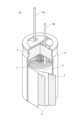
- FIG. 2 is a partially cutaway perspective view of the electrochemical device.
- a method for manufacturing an electrode for an electrochemical device with a lead member includes first to third steps.
- a slurry containing an electrode material and a current collector foil with a roughened surface are prepared.
- a slurry is applied to the surface of the current collector foil and dried to form an active layer to obtain an electrode.
- the electrode and the lead member are connected.
- the electrode material includes activated carbon as an active material and a binder as essential components.
- the active layer is a layer of electrode material. Electrodes containing activated carbon adsorb ions during charging and desorb ions during discharge.
- the slurry is intermittently applied to the current collector foil to form an uncoated area where the surface of the current collector foil is exposed in a part of the electrode.
- a lead member is attached to the uncoated area.
- an exposed part (uncoated area) of the current collecting foil By forming an exposed part (uncoated area) of the current collecting foil by intermittent coating, current collection is possible when the exposed part of the current collecting foil is formed by heat press treatment and scraping off a part of the active layer using a brush, etc. Falling off of the active layer near the exposed portion of the foil from the current collector foil is suppressed. Further, an increase in surface roughness of the exposed portion of the current collector foil and an increase in resistance at the connection portion between the electrode and the lead member due to the increase in surface roughness are suppressed. As a result, performance deterioration of the electrochemical device is suppressed.
- the binder contains an elastomer, and the content of the elastomer in the active layer (electrode material) is more than 0.25% by mass and less than 3% by mass. Note that the content of elastomer in the active layer (electrode material) means the mass ratio (percentage) of the elastomer to the entire active layer (electrode material).
- the content of elastomer in the active layer is greater than 0.25% by mass, the binding force of the active layer is increased, the adhesion between the active layer and the current collector foil is improved, and the internal resistance is small. An electrochemical device is obtained. Furthermore, the active layer is prevented from falling off, and the occurrence of micro short circuits and reduction in capacity in the electrochemical device are suppressed.
- the content of elastomer in the active layer increases to 3% by mass or more, the viscosity of the slurry used to form the active layer increases, and when the slurry is intermittently applied to the current collector foil. Trailing of the coating film may occur, which may reduce the reliability of forming exposed portions of the current collector foil.
- the content of the elastomer in the active layer is preferably 0.5% by mass or more and 2.5% by mass or less.
- Etched metal foil can be used as the current collector foil with a roughened surface. Etched foil is more advantageous than plain foil in terms of improving the adhesion between the active layer and current collector foil.
- a small amount (less than 3% by mass (or 2.5% by mass or less)) of elastomer e.g. SBR
- SBR elastomer
- the active layer containing activated carbon does not undergo large expansion and contraction unlike the active material layer of lithium ion secondary batteries (LIB), so etched foil with appropriate thickness and strength is used as the current collector foil without sacrificing energy density. It can be used for.
- LIB uses an active material (for example, graphite, Si-based active material, etc.) that absorbs and releases lithium ions, and expands and contracts significantly during charging and discharging. Considering the expansion and contraction of the active material layer and the thickness and strength of the current collector foil required for LIB, it is difficult to use etched foil for LIB.
- the slurry is prepared by dispersing the electrode material in a dispersion medium.
- the electrode material includes at least activated carbon and a binder.
- water is used as the dispersion medium.
- the content of water in the slurry is, for example, 60% by mass or more and 80% by mass or less based on the entire slurry.
- the activated carbon (activated carbon particles) that is the active material is not particularly limited, and known activated carbon used in electrochemical devices may be used.
- Activated carbon may be produced, for example, by heat-treating a raw material to carbonize it and subjecting the obtained carbide to activation treatment.
- raw materials include wood, coconut shells, pulp waste liquid, coal or coal-based pitch obtained by thermal decomposition thereof, heavy oil or petroleum-based pitch obtained by thermal decomposition thereof, phenolic resin, petroleum coke, coal coke, etc.
- the activation treatment include gas activation using a gas such as water vapor, and chemical activation using an alkali such as potassium hydroxide.
- the activated carbon particles obtained by the above activation treatment may be subjected to a pulverization treatment.
- a classification process may be performed.
- a ball mill, a jet mill, etc. are used for the pulverization process.
- the content of activated carbon in the electrode material (active layer) is not particularly limited, but may be 60% by mass or more and 95% by mass or less, or may be 70% by mass or more and 90% by mass or less.
- the content of activated carbon in the electrode material (active layer) means the mass ratio (percentage) of activated carbon to the entire electrode material (active layer).
- the binder contains at least an elastomer.
- the elastomer includes, for example, a rubber component, and may include at least one selected from the group consisting of styrene butadiene rubber (SBR), acrylic rubber, and acrylonitrile butadiene rubber. Among these, SBR is preferable from the viewpoint that the binding force of the active layer and the adhesion force between the active layer and the current collector foil can be increased with a small amount added.
- SBR styrene butadiene rubber
- acrylic rubber acrylic rubber
- acrylonitrile butadiene rubber acrylonitrile butadiene rubber
- Styrene-butadiene rubber is a copolymer containing styrene and butadiene as main monomers (for example, a copolymer of styrene and butadiene), and may be a modified version of such a copolymer.
- Acrylic rubber is a polymer whose main monomer is acrylic ester.
- acrylic rubber include copolymers of two or more monomers, including acrylic esters and other monomers, and also include modified copolymers of these.
- other monomers include 2-chloroethyl vinyl ether, acrylonitrile, and the like.
- acrylic esters include ethyl acrylate, butyl acrylate, methoxyethyl acrylate, and the like. Two or more types of acrylic esters may be used in combination.
- Acrylic rubber may be fluorinated.
- the binder may contain components other than the elastomer, for example, a resin component such as polytetrafluoroethylene (PTFE).
- a resin component such as polytetrafluoroethylene (PTFE).
- the proportion of the elastomer in the binder may be 75% by mass or more, 90% by mass or more, or 100% by mass.
- the electrode material may contain components other than activated carbon and a binder.
- Other components include a conductive agent, a thickener, and the like.
- a conductive agent for example, carbon black such as acetylene black is used.
- a thickener for example, carboxymethyl cellulose (CMC) (including alkali metal salts and ammonium salts of CMC) is used.
- the TI value of the slurry may be 2 or more and 4 or less, or 2.5 or more and 4 or less.
- the TI value of the slurry is 2 or more, trailing of the coating film is easily suppressed, and reliability in forming the exposed portion of the current collector foil is improved.
- the TI value of the slurry is 4 or less, the binding strength of the active layer is likely to be increased, and the adhesion between the active layer and the current collector foil is likely to be improved.
- the proportion of elastomer (e.g. SBR) in the electrode material is more than 0.25% by mass and less than 3% by mass (or 0.5% by mass or more and 2.5% by mass or less), the TI of the slurry is Easy to adjust within range.
- the TI value of the slurry is determined as follows.
- the viscosity of the slurry at 25° C. is measured using a B-type viscometer or an E-type viscometer.
- the viscosity ⁇ 1 of the slurry at a rotation speed of 1 rpm and the viscosity ⁇ 2 of the slurry at a rotation speed of 10 rpm are determined.
- the ratio of viscosity ⁇ 1 to viscosity ⁇ 2: ⁇ 1/ ⁇ 2 is calculated and used as a TI value.
- the arithmetic mean roughness Ra of the surface of the current collector foil is preferably 0.5 ⁇ m or more and 1 ⁇ m or less.
- the arithmetic mean roughness Ra of the surface of the etched current collector foil is, for example, 0.5 ⁇ m or more, and may be 0.6 ⁇ m or more.
- the resistance of the connection portion between the electrode (exposed portion of the current collector foil) and the lead member is likely to be reduced.
- the arithmetic mean roughness Ra is an index indicating surface roughness, and is determined in accordance with JIS B 0601:2013.
- the thickness of the current collector foil may be 30 ⁇ m or less, or 20 ⁇ m or less. By reducing the thickness of the current collector foil to 20 ⁇ m or less, the amount of active material filled can be increased and the capacity can be increased.
- an elastomer for example, SBR
- SBR elastomer
- the binding force of the active layer and the adhesion between the active layer and the current collector foil are large, and the strength of the current collector foil is high. Because it is small, it is difficult to remove part of the active layer with a brush or the like. Therefore, in the above case, it is effective to form the exposed portion of the current collector foil by intermittently applying slurry to the current collector foil.
- Materials for the current collector foil include aluminum, aluminum alloy, nickel, titanium, etc. Among these, aluminum or an aluminum alloy is preferred from the viewpoints of low cost, appropriate strength, and high electrical conductivity.
- an active layer is formed by applying a slurry to the surface of the current collector foil, drying the coating film, and compressing it if necessary.
- the dispersion medium in the slurry is removed by drying, and a layer of electrode material is formed as an active layer.
- the thickness of the active layer is, for example, 40 ⁇ m or more and 80 ⁇ m or less.
- the slurry may be applied to one surface of the current collector foil, or the slurry may be applied to both surfaces of the current collector foil.
- the slurry is intermittently applied to the current collector foil to form coated areas and uncoated areas. When applying the slurry to both sides of the current collector foil, coated areas and uncoated areas may be formed in the same pattern on both sides of the current collector foil.
- the coating method is not particularly limited as long as it allows intermittent coating, and examples include die coating, comma coating, and gravure coating.
- the die coating method is preferred as the coating method from the viewpoints that there is no contamination of foreign matter due to the sealed state and that the amount of slurry to be applied can be easily controlled by using a pump.
- a long current collector foil is supplied to the coating device, and the slurry is intermittently applied to both sides of the current collector foil to form a predetermined coating pattern, an active layer is formed, and it is cut at a predetermined position.
- a plurality of electrodes each having an exposed current collecting foil portion may be manufactured.
- the electrode and the lead member are connected by attaching the lead member to the uncoated area of the electrode.
- the lead member is attached to the uncoated area of the electrode by, for example, caulking using a needle-like member or cold pressure welding.
- the lead member includes, for example, a flat tab portion, a lead wire, and a connecting portion that connects the tab portion and the lead wire.
- the lead member is not particularly limited as long as it is an electrically conductive member having a tab portion, a connecting portion, and a lead wire, but it can be prepared as follows, for example. A metal rod-shaped member is prepared, and one end thereof is stretched flat by a press or the like to form a tab portion. The other end is left as a rod to serve as a connection.
- the connecting portion and the lead wire are connected by welding or the like.
- the connection between the electrode and the lead member by caulking is performed, for example, as follows.
- the tab portion of the lead member is placed on one surface of the uncoated region of the electrode, and an overlapping portion between the tab portion and the uncoated region is formed.
- a needle-like member is used to make a hole at a predetermined position of the overlapping portion from the tab side to form a through hole.
- a portion of the tab portion is made to protrude from the other surface of the uncoated area of the electrode to form a protrusion.
- the caulking process is performed, for example, at two to four predetermined positions within the uncoated area.
- FIG. 1 is a front view schematically showing an example of an electrode with a lead member obtained by the method for manufacturing an electrode with a lead member according to the present embodiment.
- FIG. 2 is a cross-sectional view schematically showing an example of an electrode with a lead member obtained by the method for manufacturing an electrode with a lead member according to the present embodiment.
- FIG. 2 shows a cross section including the caulking portion 40. As shown in FIG. Each member in the figure is shown schematically, and the relationship between the size and thickness of each member is not limited to this.
- the strip-shaped electrode 20 includes a current collecting foil 21 with a roughened surface and an active layer 22 supported on both sides of the current collecting foil 21.
- the electrode 20 has a collector foil exposed portion 23 in a part thereof. Exposed collector foil portions 23 are formed on both sides of the electrode 20, and when the electrode 20 is viewed from the normal direction of its main surface, the exposed collector foil portions 23 on both sides of the electrode 20 are arranged so that they almost coincide. It is formed.
- the lead member 30 includes a flat tab portion 31, a connecting portion 32, and a lead wire 33. The tab portion 31 is disposed on the exposed current collector foil portion 23 on one surface of the electrode 20 and attached by caulking. In this way, the electrode 20 and the lead member 30 are connected.
- the caulking portion 40 formed by caulking has a through hole 41 and includes a caulking piece 42 formed on the current collector foil exposed portion 23 on the other surface of the electrode 20 .
- the number of caulking parts 40 is not limited to this.
- the current collector foil exposed portion 23 is obtained by intermittent coating (formation of uncoated areas).
- a method for manufacturing an electrochemical device includes a step A of preparing a first electrode with a first lead member and a second electrode with a second lead member, the first electrode, the second electrode, and the like.
- the method includes a step B in which a wound body is obtained by winding the formed body through a separator, and a step C in which the wound body is impregnated with an electrolytic solution.
- step A at least one of the first electrode with a first lead member and the second electrode with a second lead member is obtained by the method for manufacturing an electrode for an electrochemical device with a lead member according to an embodiment of the present disclosure.
- the electrode with a lead member obtained by the method for manufacturing an electrode for an electrochemical device with a lead member according to the embodiment of the present disclosure will also be referred to as "electrode E with a lead member.”
- electrochemical devices examples include electric double layer capacitors (EDLC) and lithium ion capacitors (LIC). Note that “capacitor” may also be read as “capacitor.”
- the electrode E with a lead member may be used as at least one of the pair of electrodes with a lead member.
- the electrochemical device is an LIC, electrode E with a lead member is used as one of the pair of electrodes with a lead member (positive electrode), and a lead member used in a lithium ion secondary battery is used as the other of the pair of electrodes with a lead member (negative electrode). It is sufficient to use a negative electrode.
- a negative electrode used in a lithium ion secondary battery includes, for example, a negative electrode active material (eg, graphite) that can insert and release lithium ions.
- the electrolytic solution includes a solvent (non-aqueous solvent) and an ionic substance.
- Ionic substances are dissolved in a solvent and include cations and anions.
- the ionic substance may include, for example, a low melting point compound (ionic liquid) that can exist as a liquid at around room temperature.
- the concentration of the ionic substance in the electrolyte is, for example, 0.5 mol/L or more and 2.0 mol/L or less.
- a high boiling point solvent is preferred.
- lactones such as ⁇ -butyrolactone
- carbonates such as propylene carbonate
- polyhydric alcohols such as ethylene glycol and propylene glycol
- cyclic sulfones such as sulfolane
- N-methylacetamide N,N-dimethylformamide
- N- Amides such as methyl-2-pyrrolidone
- esters such as methyl acetate
- ethers such as 1,4-dioxane
- ketones such as methyl ethyl ketone, formaldehyde, etc.
- the ionic substance includes, for example, an organic salt.
- An organic salt is a salt in which at least one of an anion and a cation contains an organic substance.
- organic salts in which the cation includes an organic substance include quaternary ammonium salts.
- organic salts in which the anion (or both ions) contain an organic substance include trimethylamine maleate, triethylamine borodisalicylate, ethyldimethylamine phthalate, mono-1,2,3,4-tetramethylimidazolinium phthalate, and phthalate. Examples include mono-1,3-dimethyl-2-ethylimidazolinium acid.
- the anion preferably includes an anion of a fluorine-containing acid from the viewpoint of improving withstand voltage characteristics.
- the anion of the fluorine-containing acid include BF 4 - and/or PF 6 - .
- the organic salt preferably contains, for example, a cation of a tetraalkylammonium and an anion of a fluorine-containing acid. Specific examples include diethyldimethylammonium tetrafluoroborate (DEDMABF 4 ), triethylmethylammonium tetrafluoroborate (TEMABF 4 ), and the like.
- the separator has ion permeability and has the role of physically separating the pair of electrodes to prevent short circuits.
- a nonwoven fabric mainly composed of cellulose, a glass fiber mat, or a microporous film of polyolefin such as polyethylene is used.
- FIG. 3 is a partially cutaway perspective view of an electrochemical device obtained by the method for manufacturing an electrochemical device according to an embodiment of the present disclosure. Note that FIG. 3 shows an example of an electrochemical device obtained by the method for manufacturing an electrochemical device according to an embodiment of the present disclosure.
- the electrochemical device 10 in FIG. 3 is an electric double layer capacitor, and includes a wound capacitor element 1.
- the capacitor element 1 is constructed by winding a first electrode 2 and a second electrode 3 in the form of a sheet with a separator 4 in between.
- the first electrode 2 and the second electrode 3 each have a first current collector and a second current collector made of metal, and a first active layer and a second active layer supported on the surfaces thereof, and adsorb ions. Capacity is expressed by desorption and attachment.
- etched aluminum foil is used as the current collector foil.
- separator 4 for example, a nonwoven fabric containing cellulose as a main component is used.
- a first lead member 5a and a second lead member 5b are connected to the first electrode 2 and the second electrode 3, respectively.
- the capacitor element 1 is housed in a cylindrical exterior case 6 together with an electrolyte (not shown).
- the material of the exterior case 6 may be, for example, metal such as aluminum, stainless steel, copper, iron, or brass.
- the opening of the exterior case 6 is sealed with a sealing member 7.
- the lead wires 5a and 5b are led out to the outside so as to penetrate the sealing member 7.
- a rubber material such as butyl rubber is used, for example.
- Example 1 A wound type electric double layer capacitor with a rated voltage of 2.7 V was manufactured as an electrochemical device. A specific method for manufacturing an electrochemical device will be described below.
- a slurry was prepared by adding water to the electrode material.
- the electrode materials include 88.25 parts by mass of activated carbon particles, 1.75 parts by mass of styrene-butadiene rubber (SBR) as a binder, 4 parts by mass of carboxymethylcellulose (CMC) as a thickener, and a conductive agent.
- SBR styrene-butadiene rubber
- CMC carboxymethylcellulose
- AB acetylene black
- the content of SBR in the electrode material was 1.75% by mass based on the entire electrode material.
- the content of water in the slurry was 75% by mass based on the entire slurry.
- the TI value of the slurry determined by the method described above was 2.5.
- the obtained slurry was applied to both sides of a strip-shaped current collector foil, and the coating film was vacuum dried at 110°C and rolled to form an active layer (40 ⁇ m thick per side) and an electrode (length: 500 mm). , width: 59 mm) was obtained.
- Al etched foil (thickness: 20 ⁇ m, arithmetic mean roughness Ra: 0.89 ⁇ m) was used as the current collector foil.
- the slurry was applied to the current collector foil intermittently, and coated areas and uncoated areas were formed in the same pattern on both sides of the current collector foil.
- a slot die was used as the coating device.
- the current collector foil is equipped with an active layer formed on both sides of the current collector foil, and the exposed part of the current collector foil is partially formed by an uncoated area (lengthwise dimension of the electrode: 6 mm). ) was obtained.
- a lead member including a lead wire, a connecting portion, and a tab portion was prepared.
- the tab portion of the lead member was placed on one surface of the exposed current collector foil portion of the electrode, and caulking was performed at the overlapped portion of the exposed current collector foil portion and the tab portion. In this way, the tab portion was attached to the exposed portion of the current collector foil, and an electrode a1 with a lead member was obtained.
- An electrolytic solution was prepared by dissolving diethyldimethylammonium tetrafluoroborate (DEDMABF 4 ) in ⁇ -butyrolactone (GBL).
- the concentration of DEDMABF 4 in the electrolyte was 1.0 mol/L.
- Electrochemical device A1 was completed. Thereafter, aging treatment was performed at 60° C. for 16 hours while applying the rated voltage.
- the resistance (caulking resistance) between the location indicated by the arrow P1 in FIG. 1 and the location indicated by the arrow P2 in FIG. 1 was measured.
- the location indicated by the arrow P1 in FIG. 1 is the end of the lead wire 33 on the tab portion 31 side.
- the location indicated by the arrow P2 in FIG. 1 is near the end of the tab portion 31 of the current collector foil exposed portion 23 on the opposite side to the lead wire 33.
- Constant current charging was performed at a current of 1.35 A until the voltage reached 2.35 V in an environment of ⁇ 30° C., and then the state in which the voltage of 2.35 V was applied was maintained for 10 minutes. Thereafter, constant current discharge was performed at a current of 1 A in an environment of -30° C. until the voltage reached 0 V.
- Capacity C1 Id ⁇ t/V (1)
- Id is the current value at the time of discharge (1.0A)
- V is the value (0.4V) obtained by subtracting 1.6V from 2.0V.
- Constant current charging was performed at a current of 1.35 A until the voltage reached 2.35 V in an environment of ⁇ 30° C., and then the state in which the voltage of 2.35 V was applied was maintained for 10 minutes. Thereafter, constant current discharge was performed at a current of 1.35 A in an environment of -30° C. until the voltage reached 0 V.
- DCR Direct current resistance
- Constant current charging was performed at a current of 1.35 A until the voltage reached 2.5 V in an environment of 25° C., and constant voltage charging at 2.5 V was performed for 5 hours. Thereafter, the electrochemical device was left in an environment of 60° C. for 24 hours. After leaving it for 24 hours, the voltage of the electrochemical device was measured in an environment of 25°C. When the voltage of the electrochemical device after being left for 24 hours was 2.3 V or more, it was determined that micro short circuits were suppressed and the remaining capacity was high.
- Electrode b1 with lead member was produced in the same manner as in Example 1 except that polytetrafluoroethylene (PTFE) was used instead of SBR as the binder, and electrochemical device B1 was produced and evaluated.
- PTFE polytetrafluoroethylene
- ⁇ Comparative example 2 ⁇ Polytetrafluoroethylene (PTFE) was used as a binder instead of SBR.
- PTFE polytetrafluoroethylene
- the slurry was applied to the entire both sides of the current collector foil to form an active layer. Thereafter, a part of the active layer was heat pressed at a temperature of 250 to 280° C. for 3 seconds, and then removed using a brush. In this way, exposed portions of the current collector foil were formed at predetermined locations on the electrode.
- an electrode b2 with a lead member was produced in the same manner as in Example 1, and an electrochemical device B2 was produced and evaluated.
- Tables 1 and 2 show the TI values of the slurry determined by the method described above.
- the mark ⁇ in the column for trailing of the coating film indicates that no trailing of the coating film was visually observed during the intermittent application of the slurry to the current collector foil.
- an x in the column for trailing of the coating film indicates that trailing of the coating film was visually confirmed during intermittent application of the slurry to the current collector foil.
- the symbol ⁇ in the residual capacity column in Tables 1 and 2 indicates that the voltage of the electrochemical device after being left for 24 hours was 2.3 V or higher, and a high residual capacity was obtained.
- the x in the residual capacity column indicates that the voltage of the electrochemical device after being left for 24 hours was less than 2.3 V, and a low residual capacity was obtained.
- Example 1 since SBR was used as the binder, the binding force of the active layer was increased in electrode a1, and high peel strength was obtained. Furthermore, since the exposed portions of the current collector foil were formed by intermittent coating, the caulking resistance between the electrode a1 and the lead member was reduced. In electrochemical device A1, high capacity and low DCR were obtained, and high residual capacity was also obtained.
- Comparative Examples 1 and 2 PTFE was used as the binder, so in electrodes b1 and b2, the binding force of the active layer decreased and the peel strength decreased. In the electrochemical devices B1 and B2, a micro short circuit occurred and the remaining capacity decreased.
- Comparative Example 4 a portion of the active layer was removed using a brush to form an exposed portion of the current collector foil, so the caulking resistance between the electrode b4 and the lead member increased. Further, in Comparative Example 4, the thickness of the Al etched foil serving as the current collecting foil was increased to 30 ⁇ m, and the amount of filling of the active layer was reduced, resulting in a decrease in the capacity of the electrochemical device B4.
- Examples 2-3 and Comparative Examples 5-7 ⁇ A slurry was prepared by adding water to the electrode material.
- As the electrode material a mixture of 88.25 parts by mass of activated carbon particles and a total of 11.75 parts by mass of SBR, CMC, and AB was used.
- the content of SBR in the electrode material was set to the value shown in Table 2 for the entire electrode material.
- the mass ratio of SBR, CMC, and AB was 1.75:4:6.
- Electrodes a2 to a3 and b6 to b7 with lead members were fabricated in the same manner as in Example 1, except that the above slurry was used in the electrode fabrication process, and electrical Chemical devices A2 to A3 and B6 to B7 were produced and evaluated.
- Comparative Example 5 since the content of SBR in the electrode material was 0.25% by mass, the active layer was formed in the same manner as in Example 1, but the adhesion between the active layer and the current collector foil was low. It was not possible to fabricate an electrode, and the peel strength of the active layer could not be measured.
- Table 2 also shows the evaluation results of Example 1.
- Examples 1 to 3 in which the content of SBR in the active layer (electrode material) was 0.5% by mass or more and 2.5% by mass or less, the current collecting foil did not cause trailing during intermittent coating. The exposed part was stably formed. In electrodes a2 to a3, as in the case of electrode a1, the binding strength of the active layer was increased by SBR, and high peel strength was obtained. Furthermore, since the exposed portions of the current collector foil were formed by intermittent coating, the caulking resistance between the electrodes a2 to a3 and the lead member was reduced. In the electrochemical devices A2 to A3, high capacity and low DCR were obtained, as was the case with electrochemical device A1, and high residual capacity was also obtained.
- the electrode with a lead member obtained by the method for manufacturing an electrode for an electrochemical device with a lead member according to the present disclosure is suitably used in an electrochemical device that requires low internal resistance.
Landscapes
- Engineering & Computer Science (AREA)
- Power Engineering (AREA)
- Microelectronics & Electronic Packaging (AREA)
- Manufacturing & Machinery (AREA)
- Electric Double-Layer Capacitors Or The Like (AREA)
Priority Applications (3)
| Application Number | Priority Date | Filing Date | Title |
|---|---|---|---|
| CN202380030422.0A CN118946944A (zh) | 2022-03-29 | 2023-03-22 | 带引线部件的电化学装置用电极的制造方法以及电化学装置的制造方法 |
| US18/848,598 US20250246376A1 (en) | 2022-03-29 | 2023-03-22 | Method for producing lead member-equipped electrochemical device electrode, and method for producing electrochemical device |
| JP2024511959A JPWO2023189951A1 (https=) | 2022-03-29 | 2023-03-22 |
Applications Claiming Priority (2)
| Application Number | Priority Date | Filing Date | Title |
|---|---|---|---|
| JP2022-053719 | 2022-03-29 | ||
| JP2022053719 | 2022-03-29 |
Publications (1)
| Publication Number | Publication Date |
|---|---|
| WO2023189951A1 true WO2023189951A1 (ja) | 2023-10-05 |
Family
ID=88201352
Family Applications (1)
| Application Number | Title | Priority Date | Filing Date |
|---|---|---|---|
| PCT/JP2023/011257 Ceased WO2023189951A1 (ja) | 2022-03-29 | 2023-03-22 | リード部材付き電気化学デバイス用電極の製造方法および電気化学デバイスの製造方法 |
Country Status (4)
| Country | Link |
|---|---|
| US (1) | US20250246376A1 (https=) |
| JP (1) | JPWO2023189951A1 (https=) |
| CN (1) | CN118946944A (https=) |
| WO (1) | WO2023189951A1 (https=) |
Citations (6)
| Publication number | Priority date | Publication date | Assignee | Title |
|---|---|---|---|---|
| JPH0955344A (ja) * | 1995-08-11 | 1997-02-25 | Elna Co Ltd | 電気二重層コンデンサ素子の製造方法 |
| JPH11162470A (ja) * | 1997-11-25 | 1999-06-18 | Toyo Alum Kk | 集電体用アルミニウム箔とその製造方法、集電体、二次電池および電気二重層コンデンサ |
| JP2007221090A (ja) * | 2006-02-14 | 2007-08-30 | Ls Cable Ltd | 電極体−リードの接続構造、これを備えた電気二重層キャパシタ及びその製造方法 |
| JP2019029420A (ja) * | 2017-07-26 | 2019-02-21 | 旭化成株式会社 | 正極スラリー |
| WO2019156086A1 (ja) * | 2018-02-07 | 2019-08-15 | 日本ゼオン株式会社 | 電気化学素子用バインダー組成物、電気化学素子用スラリー組成物、電気化学素子用機能層および電気化学素子 |
| WO2019189414A1 (ja) * | 2018-03-27 | 2019-10-03 | 三菱ケミカル株式会社 | 非水系電解液及びそれを用いた蓄電デバイス |
-
2023
- 2023-03-22 US US18/848,598 patent/US20250246376A1/en active Pending
- 2023-03-22 CN CN202380030422.0A patent/CN118946944A/zh active Pending
- 2023-03-22 WO PCT/JP2023/011257 patent/WO2023189951A1/ja not_active Ceased
- 2023-03-22 JP JP2024511959A patent/JPWO2023189951A1/ja active Pending
Patent Citations (6)
| Publication number | Priority date | Publication date | Assignee | Title |
|---|---|---|---|---|
| JPH0955344A (ja) * | 1995-08-11 | 1997-02-25 | Elna Co Ltd | 電気二重層コンデンサ素子の製造方法 |
| JPH11162470A (ja) * | 1997-11-25 | 1999-06-18 | Toyo Alum Kk | 集電体用アルミニウム箔とその製造方法、集電体、二次電池および電気二重層コンデンサ |
| JP2007221090A (ja) * | 2006-02-14 | 2007-08-30 | Ls Cable Ltd | 電極体−リードの接続構造、これを備えた電気二重層キャパシタ及びその製造方法 |
| JP2019029420A (ja) * | 2017-07-26 | 2019-02-21 | 旭化成株式会社 | 正極スラリー |
| WO2019156086A1 (ja) * | 2018-02-07 | 2019-08-15 | 日本ゼオン株式会社 | 電気化学素子用バインダー組成物、電気化学素子用スラリー組成物、電気化学素子用機能層および電気化学素子 |
| WO2019189414A1 (ja) * | 2018-03-27 | 2019-10-03 | 三菱ケミカル株式会社 | 非水系電解液及びそれを用いた蓄電デバイス |
Also Published As
| Publication number | Publication date |
|---|---|
| US20250246376A1 (en) | 2025-07-31 |
| CN118946944A (zh) | 2024-11-12 |
| JPWO2023189951A1 (https=) | 2023-10-05 |
Similar Documents
| Publication | Publication Date | Title |
|---|---|---|
| JP6382981B2 (ja) | 低抵抗ウルトラキャパシタ電極およびその製造方法 | |
| JPH097896A (ja) | 電気二重層キャパシタ | |
| JP2013140977A (ja) | 電極、その製造方法、及びこれを含む電気化学キャパシタ | |
| KR20140051325A (ko) | 집전체, 전극 구조체, 비수전해질 전지 및 축전 부품 | |
| JP5888385B2 (ja) | 電気二重層キャパシタ用分極性電極及びそれを用いた電気二重層キャパシタ | |
| US6710999B2 (en) | Electric double layer capacitor | |
| US20240128031A1 (en) | Electrochemical capacitor | |
| JP2005129924A (ja) | 電気二重層コンデンサ用金属製集電体およびそれを用いた分極性電極並びに電気二重層コンデンサ | |
| US6830594B2 (en) | Process for producing an electric double layer capacitor and positive electrode for an electric double layer capacitor | |
| US8351182B2 (en) | Electric double layer capacitor | |
| JPH1131637A (ja) | 電気二重層キャパシタ、そのための炭素材料及び電極 | |
| KR20170113772A (ko) | 전기화학 에너지 저장장치용 집전체 및 이의 제조 방법 | |
| KR20170070339A (ko) | 전기화학 에너지 저장장치 및 그의 제조방법 | |
| WO2023189951A1 (ja) | リード部材付き電気化学デバイス用電極の製造方法および電気化学デバイスの製造方法 | |
| JP2008282838A (ja) | ハイブリット電気二重層キャパシタ | |
| KR101508646B1 (ko) | 전기화학적 에너지 저장장치 및 그 제조방법 | |
| JP2009272585A (ja) | 電気化学キャパシタ | |
| KR102837698B1 (ko) | 전해질용 첨가제, 이를 포함하는 전해질 및 에너지 저장 디바이스 | |
| JPH11283871A (ja) | 電気二重層キャパシタ用集電体及び該集電体を有する電気二重層キャパシタ | |
| JP2006269827A (ja) | 電気化学素子電極用組成物 | |
| JP2009099978A (ja) | 電気二重層キャパシタ用分極性電極及びそれを用いた電気二重層キャパシタ | |
| JP2010141065A (ja) | 蓄電デバイス | |
| KR102731894B1 (ko) | 저저항 및 고신뢰성을 가지는 전기 이중충 커패시터 | |
| JP5206443B2 (ja) | 電気化学素子用電極、および電気化学素子 | |
| JPH09275041A (ja) | 電気二重層キャパシタ |
Legal Events
| Date | Code | Title | Description |
|---|---|---|---|
| 121 | Ep: the epo has been informed by wipo that ep was designated in this application |
Ref document number: 23779963 Country of ref document: EP Kind code of ref document: A1 |
|
| WWE | Wipo information: entry into national phase |
Ref document number: 2024511959 Country of ref document: JP |
|
| WWE | Wipo information: entry into national phase |
Ref document number: 18848598 Country of ref document: US |
|
| WWE | Wipo information: entry into national phase |
Ref document number: 202380030422.0 Country of ref document: CN |
|
| NENP | Non-entry into the national phase |
Ref country code: DE |
|
| 122 | Ep: pct application non-entry in european phase |
Ref document number: 23779963 Country of ref document: EP Kind code of ref document: A1 |
|
| WWP | Wipo information: published in national office |
Ref document number: 18848598 Country of ref document: US |