WO2023189865A1 - 車両の後部構造 - Google Patents
車両の後部構造 Download PDFInfo
- Publication number
- WO2023189865A1 WO2023189865A1 PCT/JP2023/011035 JP2023011035W WO2023189865A1 WO 2023189865 A1 WO2023189865 A1 WO 2023189865A1 JP 2023011035 W JP2023011035 W JP 2023011035W WO 2023189865 A1 WO2023189865 A1 WO 2023189865A1
- Authority
- WO
- WIPO (PCT)
- Prior art keywords
- vehicle
- bumper reinforcement
- reinforcing plate
- rear bumper
- pair
- Prior art date
- Legal status (The legal status is an assumption and is not a legal conclusion. Google has not performed a legal analysis and makes no representation as to the accuracy of the status listed.)
- Ceased
Links
Images



Classifications
-
- B—PERFORMING OPERATIONS; TRANSPORTING
- B60—VEHICLES IN GENERAL
- B60R—VEHICLES, VEHICLE FITTINGS, OR VEHICLE PARTS, NOT OTHERWISE PROVIDED FOR
- B60R19/00—Wheel guards; Radiator guards, e.g. grilles; Obstruction removers; Fittings damping bouncing force in collisions
- B60R19/02—Bumpers, i.e. impact receiving or absorbing members for protecting vehicles or fending off blows from other vehicles or objects
- B60R19/04—Bumpers, i.e. impact receiving or absorbing members for protecting vehicles or fending off blows from other vehicles or objects formed from more than one section in a side-by-side arrangement
-
- B—PERFORMING OPERATIONS; TRANSPORTING
- B60—VEHICLES IN GENERAL
- B60R—VEHICLES, VEHICLE FITTINGS, OR VEHICLE PARTS, NOT OTHERWISE PROVIDED FOR
- B60R19/00—Wheel guards; Radiator guards, e.g. grilles; Obstruction removers; Fittings damping bouncing force in collisions
- B60R19/02—Bumpers, i.e. impact receiving or absorbing members for protecting vehicles or fending off blows from other vehicles or objects
- B60R19/24—Arrangements for mounting bumpers on vehicles
- B60R19/26—Arrangements for mounting bumpers on vehicles comprising yieldable mounting means
- B60R19/34—Arrangements for mounting bumpers on vehicles comprising yieldable mounting means destroyed upon impact, e.g. one-shot type
-
- B—PERFORMING OPERATIONS; TRANSPORTING
- B60—VEHICLES IN GENERAL
- B60R—VEHICLES, VEHICLE FITTINGS, OR VEHICLE PARTS, NOT OTHERWISE PROVIDED FOR
- B60R19/00—Wheel guards; Radiator guards, e.g. grilles; Obstruction removers; Fittings damping bouncing force in collisions
- B60R19/02—Bumpers, i.e. impact receiving or absorbing members for protecting vehicles or fending off blows from other vehicles or objects
- B60R19/48—Bumpers, i.e. impact receiving or absorbing members for protecting vehicles or fending off blows from other vehicles or objects combined with, or convertible into, other devices or objects, e.g. bumpers combined with road brushes, bumpers convertible into beds
-
- B—PERFORMING OPERATIONS; TRANSPORTING
- B60—VEHICLES IN GENERAL
- B60R—VEHICLES, VEHICLE FITTINGS, OR VEHICLE PARTS, NOT OTHERWISE PROVIDED FOR
- B60R19/00—Wheel guards; Radiator guards, e.g. grilles; Obstruction removers; Fittings damping bouncing force in collisions
- B60R19/56—Fittings damping bouncing force in truck collisions, e.g. bumpers; Arrangements on high-riding vehicles, e.g. lorries, for preventing vehicles or objects from running thereunder
Definitions
- the present invention relates to a rear structure of a vehicle.
- a vehicle rear structure In order to protect the rear part of the vehicle in the event of a rear-end collision, a vehicle rear structure has been proposed in which a beam extending in the vehicle width direction is connected to the rear ends of a pair of side frames via brackets (see Patent Document 1).
- the bracket and the beam are connected by a fuse bolt that breaks when a predetermined load is exceeded.
- the other vehicle collides with the beam and the fuse bolt breaks, causing the beam to descend and cause the beam to fall. Prevents infiltration.
- the height of the upper surface of the bumper reinforcement should be the optimal height for placing the feet, and the lower surface of the bumper reinforcement should be must be high enough to ensure a sufficient departure angle.
- Departure angle is the angle between the ground and an imaginary line connecting the rear end of the vehicle and the point where the rear wheels touch the ground, and is a measure of the vehicle's ability to overcome uneven ground. Therefore, in a vehicle in which the bumper reinforcement is also used as a foot step, the vertical thickness of the bumper reinforcement is restricted to a relatively small dimension in order to satisfy the above conditions.
- the present invention has been made in view of the above circumstances, and provides a rear structure of a vehicle that is advantageous in protecting the rear of the vehicle in the event of a rear collision in a vehicle in which a bumper reinforcement is also used as a foot step.
- the purpose is to
- an embodiment of the present invention includes a pair of arms that extend toward the rear of the vehicle from the rear ends of a pair of side frames, and a pair of arms that extend in the vehicle width direction.
- a rear bumper structure for a vehicle comprising: a rear bumper structure that is connected to the rear bumper structure and whose upper surface functions as a step on which a foot is placed;
- a plate-shaped reinforcement plate extending along the rear bumper reinforcement is joined to the rear bumper reinforcement, and the width of the reinforcement plate in the vehicle vertical direction is larger than the width of the rear bumper reinforcement in the vehicle vertical direction. It is characterized by
- the load input from the rear of the vehicle during a rear collision can be reliably absorbed by the rear bumper reinforcement reinforced by the reinforcement plate.
- the vertical width of the reinforcing plate is larger than the vertical width of the rear bumper reinforcement, which prevents the front of the other vehicle from sliding into the rear of the vehicle in the event of a rear-end collision. This is advantageous in terms of protecting the rear part of the vehicle.
- FIG. 2 is a perspective view showing the rear structure of the vehicle according to the first embodiment.
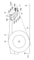
- FIG. 2 is a side view showing the rear structure of the vehicle according to the first embodiment.
- FIG. 3 is a perspective view showing a state in which a rear bumper reinforcement, a reinforcing plate, and an arm are assembled.
- FIG. 7 is a perspective view showing a bead provided on a reinforcing plate and a stopper provided on an arm in a second embodiment. It is a perspective view which shows the bead provided in the reinforcement plate and the stopper provided in the arm in 3rd Embodiment.
- FIG. 1 is a perspective view showing the rear part of a vehicle to which the vehicle rear structure according to the embodiment is applied.
- a pickup truck 10 is a vehicle to which the vehicle rear structure of this embodiment is applied.
- the pickup truck 10 is a frame vehicle in which a cabin 14 and a cargo box 16 are mounted on a ladder frame 12.
- the ladder frame 12 includes a pair of side frames 18 and a plurality of cross members 20 that connect the pair of side frames 18.
- the rear structure of the vehicle includes a rear bumper structure formed by a pair of arms 22 and a rear bumper reinforcement 24, and a reinforcing plate 26.
- the pair of arms 22 are made of steel and are provided to extend toward the rear of the vehicle from the rear ends of the pair of side frames 18, respectively.
- Each arm 22 includes a vertical plate portion 2202 extending obliquely in the vehicle vertical direction and rearward of the vehicle, and a pair of flange portions 2204 bent outward in the vehicle width direction from both ends of the vertical plate portion 2202. It is configured.
- the pair of flange portions 2204 extend over the entire length of the vertical plate portion 2202.
- the upper ends of the vertical plate portions 2202 are attached to the outer surfaces of the pair of side frames 18 with bolts.
- the vertical plate portion 2202 is formed such that the vertical width of the vertical plate portion 2202 gradually decreases toward the rear of the vehicle.
- Holes 2206 are formed through the vertical plate portion 2202 at a plurality of locations spaced apart in the extending direction.
- the portion through which the hole 2206 is formed constitutes a deformation inducing portion 23 that is more likely to deform than other portions in the event of a rear collision.
- the rear bumper reinforcement 24 functions as a member that absorbs the load applied during a rear collision, and at the same time, its upper surface functions as a step on which to place your feet when getting on and off the cargo box 16. It is.
- the rear bumper reinforcement 24 is arranged to extend in the vehicle width direction and connect the pair of arms 22.
- the rear bumper reinforcement 24 is made of steel, has a front wall 2402 and a rear wall 2404 that face each other in the longitudinal direction of the vehicle, and an upper wall 2406 and a lower wall 2408 that face each other in the vertical direction, and has a hollow rectangular cross section. It is formed.
- the height of the upper wall 2406 of the rear bumper reinforcement 24 is set so that it is the optimum height for placing feet.
- the height of the lower wall 2408 of the rear bumper reinforcement 24 is set in order to ensure a departure angle.
- the width in the longitudinal direction of the vehicle (the distance between the front wall 2402 and the rear wall 2404) is set in consideration of the strength, rigidity, etc. of the rear bumper reinforcement 24.
- the width in the longitudinal direction of the vehicle is larger than the width in the vertical direction of the vehicle.
- the rear bumper reinforcement 24 has both sides 24A in the vehicle width direction, and a central part 24B that is lower in height than the both sides 24A and functions as a step. Both side parts 24A of the rear bumper reinforcement 24 are placed on the flange part 2204 above the rear end of the arm 22, and are joined to the flange part 2204 by welding.
- the reinforcing plate 26 is a plate-shaped member that reinforces the rear bumper reinforcement 24, and is made of sheet metal.
- the reinforcing plate 26 extends in the vehicle width direction over substantially the entire length between the pair of arms 22.
- the reinforcing plate 26 includes a main body plate part 2602 that extends in the vehicle vertical direction while being attached to the rear bumper reinforcement 24, and a bent plate part 2604 that projects from the upper end of the main body plate part 2602 toward the rear of the vehicle. ing.
- the lower end of the main body plate portion 2602 is located below the rear bumper reinforcement 24, as shown in FIG.
- the upper end of the main body plate portion 2602 is located at the same height as the upper wall 2406 of the rear bumper reinforcement 24, as shown in FIG.
- the bent plate portion 2604 includes a central bent plate portion 2604A provided at the center portion 24B of the main body plate portion 2602 in the vehicle width direction and located above the center portion 24B of the rear bumper reinforcement 24, and a center bent plate portion 2604A provided in the center portion 24B of the main body plate portion 2602 in the vehicle width direction. and end bent plate portions 2604B located above both side portions 24A of the rear bumper reinforcement 24.
- the central bent plate portion 2604A and the pair of end bent plate portions 2604B are joined to the upper wall 2406 of the rear bumper reinforcement 24 by welding. Therefore, in this embodiment, the width of the reinforcing plate 26 in the vehicle vertical direction is larger than the width of the rear bumper reinforcement 24 in the vertical direction.
- beads 2606 that are convex toward the front of the vehicle and extend in the vertical direction are formed at multiple locations spaced apart in the vehicle width direction on the main body plate portion 2602.
- the upper part of the bead 2606 overlaps with the front wall 2402 of the rear bumper reinforcement 24 when viewed from the vehicle longitudinal direction.
- the lower end of the reinforcing plate 26 is an imaginary line connecting the rear end of the rear bumper structure (in this embodiment, the lower end of the rear end of the arm 22) and the point where the rear wheel 28 touches the ground 30. It is located above the line L, that is, so as to overlap the virtual line L, or is located above the virtual line L.
- a synthetic resin bumper cover 32 as a design component is provided from above the rear bumper reinforcement 24 and the reinforcing plate 26, and the rear bumper reinforcement 24 and the reinforcing plate 26 are connected to each other by the bumper cover 32. covered.
- the vertical width of the reinforcing plate 26 attached to the rear bumper reinforcement 24 is larger than the vertical width of the rear bumper reinforcement 24. Therefore, even though the rear bumper reinforcement 24 is formed with a small vertical width because it also serves as a step, the reinforcing plate 26 can catch the other vehicle in the event of a rear collision. can be protected.
- the lower end of the reinforcing plate 26 is located below the rear bumper reinforcement 24, it is possible to suppress the other vehicle from sneaking into the own vehicle in the event of a rear collision.
- the lower end of the reinforcing plate 26 is located below an imaginary line L connecting the lower end of the rear bumper structure, in this embodiment the rear end of the arm 22, and the point where the rear wheel 28 touches the ground 30.
- the departure angle ⁇ is the angle that the imaginary line L' connecting the lower end of the reinforcing plate 26 and the point where the rear wheel 28 touches the ground 30 makes with the ground 30, so the effect of securing the departure angle ⁇ is decreases.
- the lower end of the reinforcing plate 26 is located above the imaginary line L.
- the lower end of the reinforcing plate 26 is positioned below the imaginary line L connecting the rear end of the rear bumper reinforcement 24 and the point where the rear wheel 28 touches the ground 30.
- a reinforcing plate 26 is joined to the front end of the rear bumper reinforcement 24 of the vehicle. Therefore, compared to the case where the reinforcing plate 26 is joined to the vehicle rear end of the rear bumper reinforcement 24, the lower end of the reinforcing plate 26 can be positioned below the vehicle while ensuring the departure angle ⁇ .
- each arm 22 is provided with a deformation inducing section 23, the load can be controlled by deforming each arm 22 in the event of a rear collision, thereby suppressing deformation of the rear part of the side frame 18. This is advantageous in terms of protecting the rear part of the vehicle.
- the reinforcing plate 26 is formed with beads 2606 extending in the vertical direction at a plurality of locations spaced apart in the vehicle width direction, and the beads 2606 are formed as rear bumper reinforcements when viewed from the vehicle longitudinal direction. It overlaps with 24. Therefore, the reinforcing plate 26 is reinforced by the plurality of beads 2606, and when the reinforcing plate 26 tries to deform during a rear collision, the load input to the reinforcing plate is transferred to the rear bumper reinforcement through the plurality of beads 2606. 24, which is advantageous in enhancing the reinforcing effect of the reinforcing plate 26.
- beads 2606 at both ends of the reinforcing plate 26 in the vehicle width direction are added to the rear structure of the vehicle in the first embodiment when the rear bumper reinforcement 24 is deformed toward the front of the vehicle during a rear collision.
- a stopper 34A that comes into contact with (a pair of end beads) is provided on the inner surface in the vehicle width direction of the vertical plate portion 2202 of the arm 22.
- the bead 2606 includes a first wall portion 2606A that stands up from the front surface of the main body plate portion 2602 facing the front of the vehicle toward the front of the vehicle, and a first wall portion 2606A that extends from the first wall portion 2606A in the vehicle vertical direction and the vehicle width direction and extends toward the vehicle front. It has a second wall portion 2606B facing toward the second wall portion 2606B, and a ridge line 2608 that is a boundary between the first wall portion 2606A and the second wall portion 2606B. Of these ridgelines 2608, a pair of portions extending linearly in the vertical direction that are spaced apart in the vehicle width direction are defined as a pair of ridgeline portions 2610.
- the stopper 34A extends inward in the vehicle width direction from the inner surface in the vehicle width direction of the vertical plate portion 2202 of the arm 22 so as to straddle the pair of ridgeline portions 2610 and face the bead 2606. That is, the stopper 34A overlaps with the bead 2606 when viewed from the front-rear direction of the vehicle. According to the second embodiment, when the reinforcing plate 26 is about to deform during a rear collision, the bead 2606 comes into contact with the stopper 34A, which is advantageous in suppressing the deformation of the reinforcing plate 26. Become.
- bent pieces 2612 are provided at both ends of the reinforcing plate 26 in the vehicle width direction in the rear structure of the vehicle of the second embodiment. Specifically, the bent piece 2612 is provided by bending both ends of the main body plate portion 2602 of the reinforcing plate 26 in the vehicle width direction toward the front of the vehicle. The bent piece 2612 extends over almost the entire length of the vertical width of the main body plate portion 2602.
- the front end of the bent piece 2612 and the ridgeline portions 2610 of the bead 2606 located at both ends of the reinforcing plate 26 in the vehicle width direction are located at the same position in the longitudinal direction of the vehicle.
- the stopper 34B is provided so as to overlap the ridgeline portion 2610 and the bent piece 2612 located on the outside in the vehicle width direction when viewed from the vehicle vertical direction.
- the inner end of the stopper 34B in the vehicle width direction is located between the ridgeline portion 2610 located on the outer side in the vehicle width direction and the ridgeline portion 2610 located on the inner side in the vehicle width direction.
- the third embodiment is advantageous in making the stopper 34B smaller and lighter than the second embodiment.
- the third embodiment also provides the same effects as the second embodiment.
- the present embodiment describes the case where the vehicle is the pickup truck 10
- the present invention is of course applicable to vehicles other than the pickup truck 10.
Landscapes
- Engineering & Computer Science (AREA)
- Mechanical Engineering (AREA)
- Body Structure For Vehicles (AREA)
Priority Applications (1)
| Application Number | Priority Date | Filing Date | Title |
|---|---|---|---|
| JP2024511915A JP7740522B2 (ja) | 2022-03-29 | 2023-03-20 | 車両の後部構造 |
Applications Claiming Priority (2)
| Application Number | Priority Date | Filing Date | Title |
|---|---|---|---|
| JP2022053616 | 2022-03-29 | ||
| JP2022-053616 | 2022-03-29 |
Publications (1)
| Publication Number | Publication Date |
|---|---|
| WO2023189865A1 true WO2023189865A1 (ja) | 2023-10-05 |
Family
ID=88201232
Family Applications (1)
| Application Number | Title | Priority Date | Filing Date |
|---|---|---|---|
| PCT/JP2023/011035 Ceased WO2023189865A1 (ja) | 2022-03-29 | 2023-03-20 | 車両の後部構造 |
Country Status (2)
| Country | Link |
|---|---|
| JP (1) | JP7740522B2 (https=) |
| WO (1) | WO2023189865A1 (https=) |
Citations (6)
| Publication number | Priority date | Publication date | Assignee | Title |
|---|---|---|---|---|
| US3137516A (en) * | 1963-04-12 | 1964-06-16 | Ted L Cline | Safety bumper having illuminated recess for license plate |
| JP2001001953A (ja) * | 1999-06-21 | 2001-01-09 | Araco Corp | ステップステー |
| JP2006036079A (ja) * | 2004-07-28 | 2006-02-09 | Honda Motor Co Ltd | 車両用バンパー構造 |
| WO2007080687A1 (ja) * | 2006-01-12 | 2007-07-19 | Isuzu Motors Limited | 車両のアンダーランプロテクタ取付構造 |
| JP2008006961A (ja) * | 2006-06-29 | 2008-01-17 | Mazda Motor Corp | 自動車のバンパ構造 |
| JP2013203129A (ja) * | 2012-03-27 | 2013-10-07 | Isuzu Motors Ltd | アンダーランプロテクタ構造 |
-
2023
- 2023-03-20 JP JP2024511915A patent/JP7740522B2/ja active Active
- 2023-03-20 WO PCT/JP2023/011035 patent/WO2023189865A1/ja not_active Ceased
Patent Citations (6)
| Publication number | Priority date | Publication date | Assignee | Title |
|---|---|---|---|---|
| US3137516A (en) * | 1963-04-12 | 1964-06-16 | Ted L Cline | Safety bumper having illuminated recess for license plate |
| JP2001001953A (ja) * | 1999-06-21 | 2001-01-09 | Araco Corp | ステップステー |
| JP2006036079A (ja) * | 2004-07-28 | 2006-02-09 | Honda Motor Co Ltd | 車両用バンパー構造 |
| WO2007080687A1 (ja) * | 2006-01-12 | 2007-07-19 | Isuzu Motors Limited | 車両のアンダーランプロテクタ取付構造 |
| JP2008006961A (ja) * | 2006-06-29 | 2008-01-17 | Mazda Motor Corp | 自動車のバンパ構造 |
| JP2013203129A (ja) * | 2012-03-27 | 2013-10-07 | Isuzu Motors Ltd | アンダーランプロテクタ構造 |
Also Published As
| Publication number | Publication date |
|---|---|
| JPWO2023189865A1 (https=) | 2023-10-05 |
| JP7740522B2 (ja) | 2025-09-17 |
Similar Documents
| Publication | Publication Date | Title |
|---|---|---|
| US7900995B2 (en) | Vehicle body structure | |
| US7950705B2 (en) | Underrun protector mounting structure of vehicle | |
| EP2065246B1 (en) | Canister mounting structure | |
| JP5895701B2 (ja) | 車体前部構造 | |
| US8020925B2 (en) | Front structure of cab-over type vehicle | |
| CA2876053A1 (en) | Fender supporting portion structure | |
| JP4207904B2 (ja) | 車両端部構造 | |
| JP4314992B2 (ja) | 車体構造 | |
| JP4680531B2 (ja) | 自動車の前部車体構造 | |
| JP4271164B2 (ja) | 自動車の前部車体構造 | |
| JP5151495B2 (ja) | 自動車のフードストッパ構造 | |
| WO2015080087A1 (ja) | アンダランプロテクタの構造 | |
| JP7740522B2 (ja) | 車両の後部構造 | |
| US7472948B2 (en) | Vehicle body structure | |
| JP2018177124A (ja) | 車両前部構造 | |
| CN100532143C (zh) | 牵引钩安装结构 | |
| CN110962936B (zh) | 横梁结构和车架 | |
| JP2022036512A (ja) | 車体前部構造 | |
| JP5760979B2 (ja) | 車両の前部構造 | |
| JP7246836B2 (ja) | 車両前部構造 | |
| CN114954675A (zh) | 前车身结构 | |
| JP5496727B2 (ja) | 自動車の前部車体構造 | |
| JP4798485B2 (ja) | 車両のフロントバンパー構造 | |
| JP6922487B2 (ja) | トラックの車体構造 | |
| JPH11115820A (ja) | 車両の後部車体構造 |
Legal Events
| Date | Code | Title | Description |
|---|---|---|---|
| 121 | Ep: the epo has been informed by wipo that ep was designated in this application |
Ref document number: 23776837 Country of ref document: EP Kind code of ref document: A1 |
|
| ENP | Entry into the national phase |
Ref document number: 2024511915 Country of ref document: JP Kind code of ref document: A |
|
| WWE | Wipo information: entry into national phase |
Ref document number: 2401006165 Country of ref document: TH |
|
| WWE | Wipo information: entry into national phase |
Ref document number: 12024552335 Country of ref document: PH |
|
| NENP | Non-entry into the national phase |
Ref country code: DE |
|
| 122 | Ep: pct application non-entry in european phase |
Ref document number: 23776837 Country of ref document: EP Kind code of ref document: A1 |