WO2023189865A1 - Vehicle rear structure - Google Patents
Vehicle rear structure Download PDFInfo
- Publication number
- WO2023189865A1 WO2023189865A1 PCT/JP2023/011035 JP2023011035W WO2023189865A1 WO 2023189865 A1 WO2023189865 A1 WO 2023189865A1 JP 2023011035 W JP2023011035 W JP 2023011035W WO 2023189865 A1 WO2023189865 A1 WO 2023189865A1
- Authority
- WO
- WIPO (PCT)
- Prior art keywords
- vehicle
- bumper reinforcement
- reinforcing plate
- rear bumper
- pair
- Prior art date
Links
- 230000002787 reinforcement Effects 0.000 claims abstract description 62
- 230000003014 reinforcing effect Effects 0.000 claims abstract description 44
- 239000011324 bead Substances 0.000 claims description 21
- 230000001939 inductive effect Effects 0.000 claims description 4
- 230000000694 effects Effects 0.000 description 3
- 229910000831 Steel Inorganic materials 0.000 description 2
- 230000007423 decrease Effects 0.000 description 2
- 230000004048 modification Effects 0.000 description 2
- 238000012986 modification Methods 0.000 description 2
- 239000010959 steel Substances 0.000 description 2
- 238000003466 welding Methods 0.000 description 2
- 238000005452 bending Methods 0.000 description 1
- 239000000470 constituent Substances 0.000 description 1
- 230000002708 enhancing effect Effects 0.000 description 1
- 230000008595 infiltration Effects 0.000 description 1
- 238000001764 infiltration Methods 0.000 description 1
- 239000002184 metal Substances 0.000 description 1
- 229920003002 synthetic resin Polymers 0.000 description 1
- 239000000057 synthetic resin Substances 0.000 description 1
Images


Classifications
-
- B—PERFORMING OPERATIONS; TRANSPORTING
- B60—VEHICLES IN GENERAL
- B60R—VEHICLES, VEHICLE FITTINGS, OR VEHICLE PARTS, NOT OTHERWISE PROVIDED FOR
- B60R19/00—Wheel guards; Radiator guards, e.g. grilles; Obstruction removers; Fittings damping bouncing force in collisions
- B60R19/02—Bumpers, i.e. impact receiving or absorbing members for protecting vehicles or fending off blows from other vehicles or objects
- B60R19/04—Bumpers, i.e. impact receiving or absorbing members for protecting vehicles or fending off blows from other vehicles or objects formed from more than one section in a side-by-side arrangement
-
- B—PERFORMING OPERATIONS; TRANSPORTING
- B60—VEHICLES IN GENERAL
- B60R—VEHICLES, VEHICLE FITTINGS, OR VEHICLE PARTS, NOT OTHERWISE PROVIDED FOR
- B60R19/00—Wheel guards; Radiator guards, e.g. grilles; Obstruction removers; Fittings damping bouncing force in collisions
- B60R19/02—Bumpers, i.e. impact receiving or absorbing members for protecting vehicles or fending off blows from other vehicles or objects
- B60R19/24—Arrangements for mounting bumpers on vehicles
- B60R19/26—Arrangements for mounting bumpers on vehicles comprising yieldable mounting means
- B60R19/34—Arrangements for mounting bumpers on vehicles comprising yieldable mounting means destroyed upon impact, e.g. one-shot type
-
- B—PERFORMING OPERATIONS; TRANSPORTING
- B60—VEHICLES IN GENERAL
- B60R—VEHICLES, VEHICLE FITTINGS, OR VEHICLE PARTS, NOT OTHERWISE PROVIDED FOR
- B60R19/00—Wheel guards; Radiator guards, e.g. grilles; Obstruction removers; Fittings damping bouncing force in collisions
- B60R19/02—Bumpers, i.e. impact receiving or absorbing members for protecting vehicles or fending off blows from other vehicles or objects
- B60R19/48—Bumpers, i.e. impact receiving or absorbing members for protecting vehicles or fending off blows from other vehicles or objects combined with, or convertible into, other devices or objects, e.g. bumpers combined with road brushes, bumpers convertible into beds
-
- B—PERFORMING OPERATIONS; TRANSPORTING
- B60—VEHICLES IN GENERAL
- B60R—VEHICLES, VEHICLE FITTINGS, OR VEHICLE PARTS, NOT OTHERWISE PROVIDED FOR
- B60R19/00—Wheel guards; Radiator guards, e.g. grilles; Obstruction removers; Fittings damping bouncing force in collisions
- B60R19/56—Fittings damping bouncing force in truck collisions, e.g. bumpers; Arrangements on high-riding vehicles, e.g. lorries, for preventing vehicles or objects from running thereunder
Definitions
- the present invention relates to a rear structure of a vehicle.
- a vehicle rear structure In order to protect the rear part of the vehicle in the event of a rear-end collision, a vehicle rear structure has been proposed in which a beam extending in the vehicle width direction is connected to the rear ends of a pair of side frames via brackets (see Patent Document 1).
- the bracket and the beam are connected by a fuse bolt that breaks when a predetermined load is exceeded.
- the other vehicle collides with the beam and the fuse bolt breaks, causing the beam to descend and cause the beam to fall. Prevents infiltration.
- the height of the upper surface of the bumper reinforcement should be the optimal height for placing the feet, and the lower surface of the bumper reinforcement should be must be high enough to ensure a sufficient departure angle.
- Departure angle is the angle between the ground and an imaginary line connecting the rear end of the vehicle and the point where the rear wheels touch the ground, and is a measure of the vehicle's ability to overcome uneven ground. Therefore, in a vehicle in which the bumper reinforcement is also used as a foot step, the vertical thickness of the bumper reinforcement is restricted to a relatively small dimension in order to satisfy the above conditions.
- the present invention has been made in view of the above circumstances, and provides a rear structure of a vehicle that is advantageous in protecting the rear of the vehicle in the event of a rear collision in a vehicle in which a bumper reinforcement is also used as a foot step.
- the purpose is to
- an embodiment of the present invention includes a pair of arms that extend toward the rear of the vehicle from the rear ends of a pair of side frames, and a pair of arms that extend in the vehicle width direction.
- a rear bumper structure for a vehicle comprising: a rear bumper structure that is connected to the rear bumper structure and whose upper surface functions as a step on which a foot is placed;
- a plate-shaped reinforcement plate extending along the rear bumper reinforcement is joined to the rear bumper reinforcement, and the width of the reinforcement plate in the vehicle vertical direction is larger than the width of the rear bumper reinforcement in the vehicle vertical direction. It is characterized by
- the load input from the rear of the vehicle during a rear collision can be reliably absorbed by the rear bumper reinforcement reinforced by the reinforcement plate.
- the vertical width of the reinforcing plate is larger than the vertical width of the rear bumper reinforcement, which prevents the front of the other vehicle from sliding into the rear of the vehicle in the event of a rear-end collision. This is advantageous in terms of protecting the rear part of the vehicle.
- FIG. 2 is a perspective view showing the rear structure of the vehicle according to the first embodiment.
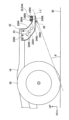
- FIG. 2 is a side view showing the rear structure of the vehicle according to the first embodiment.
- FIG. 3 is a perspective view showing a state in which a rear bumper reinforcement, a reinforcing plate, and an arm are assembled.
- FIG. 7 is a perspective view showing a bead provided on a reinforcing plate and a stopper provided on an arm in a second embodiment. It is a perspective view which shows the bead provided in the reinforcement plate and the stopper provided in the arm in 3rd Embodiment.
- FIG. 1 is a perspective view showing the rear part of a vehicle to which the vehicle rear structure according to the embodiment is applied.
- a pickup truck 10 is a vehicle to which the vehicle rear structure of this embodiment is applied.
- the pickup truck 10 is a frame vehicle in which a cabin 14 and a cargo box 16 are mounted on a ladder frame 12.
- the ladder frame 12 includes a pair of side frames 18 and a plurality of cross members 20 that connect the pair of side frames 18.
- the rear structure of the vehicle includes a rear bumper structure formed by a pair of arms 22 and a rear bumper reinforcement 24, and a reinforcing plate 26.
- the pair of arms 22 are made of steel and are provided to extend toward the rear of the vehicle from the rear ends of the pair of side frames 18, respectively.
- Each arm 22 includes a vertical plate portion 2202 extending obliquely in the vehicle vertical direction and rearward of the vehicle, and a pair of flange portions 2204 bent outward in the vehicle width direction from both ends of the vertical plate portion 2202. It is configured.
- the pair of flange portions 2204 extend over the entire length of the vertical plate portion 2202.
- the upper ends of the vertical plate portions 2202 are attached to the outer surfaces of the pair of side frames 18 with bolts.
- the vertical plate portion 2202 is formed such that the vertical width of the vertical plate portion 2202 gradually decreases toward the rear of the vehicle.
- Holes 2206 are formed through the vertical plate portion 2202 at a plurality of locations spaced apart in the extending direction.
- the portion through which the hole 2206 is formed constitutes a deformation inducing portion 23 that is more likely to deform than other portions in the event of a rear collision.
- the rear bumper reinforcement 24 functions as a member that absorbs the load applied during a rear collision, and at the same time, its upper surface functions as a step on which to place your feet when getting on and off the cargo box 16. It is.
- the rear bumper reinforcement 24 is arranged to extend in the vehicle width direction and connect the pair of arms 22.
- the rear bumper reinforcement 24 is made of steel, has a front wall 2402 and a rear wall 2404 that face each other in the longitudinal direction of the vehicle, and an upper wall 2406 and a lower wall 2408 that face each other in the vertical direction, and has a hollow rectangular cross section. It is formed.
- the height of the upper wall 2406 of the rear bumper reinforcement 24 is set so that it is the optimum height for placing feet.
- the height of the lower wall 2408 of the rear bumper reinforcement 24 is set in order to ensure a departure angle.
- the width in the longitudinal direction of the vehicle (the distance between the front wall 2402 and the rear wall 2404) is set in consideration of the strength, rigidity, etc. of the rear bumper reinforcement 24.
- the width in the longitudinal direction of the vehicle is larger than the width in the vertical direction of the vehicle.
- the rear bumper reinforcement 24 has both sides 24A in the vehicle width direction, and a central part 24B that is lower in height than the both sides 24A and functions as a step. Both side parts 24A of the rear bumper reinforcement 24 are placed on the flange part 2204 above the rear end of the arm 22, and are joined to the flange part 2204 by welding.
- the reinforcing plate 26 is a plate-shaped member that reinforces the rear bumper reinforcement 24, and is made of sheet metal.
- the reinforcing plate 26 extends in the vehicle width direction over substantially the entire length between the pair of arms 22.
- the reinforcing plate 26 includes a main body plate part 2602 that extends in the vehicle vertical direction while being attached to the rear bumper reinforcement 24, and a bent plate part 2604 that projects from the upper end of the main body plate part 2602 toward the rear of the vehicle. ing.
- the lower end of the main body plate portion 2602 is located below the rear bumper reinforcement 24, as shown in FIG.
- the upper end of the main body plate portion 2602 is located at the same height as the upper wall 2406 of the rear bumper reinforcement 24, as shown in FIG.
- the bent plate portion 2604 includes a central bent plate portion 2604A provided at the center portion 24B of the main body plate portion 2602 in the vehicle width direction and located above the center portion 24B of the rear bumper reinforcement 24, and a center bent plate portion 2604A provided in the center portion 24B of the main body plate portion 2602 in the vehicle width direction. and end bent plate portions 2604B located above both side portions 24A of the rear bumper reinforcement 24.
- the central bent plate portion 2604A and the pair of end bent plate portions 2604B are joined to the upper wall 2406 of the rear bumper reinforcement 24 by welding. Therefore, in this embodiment, the width of the reinforcing plate 26 in the vehicle vertical direction is larger than the width of the rear bumper reinforcement 24 in the vertical direction.
- beads 2606 that are convex toward the front of the vehicle and extend in the vertical direction are formed at multiple locations spaced apart in the vehicle width direction on the main body plate portion 2602.
- the upper part of the bead 2606 overlaps with the front wall 2402 of the rear bumper reinforcement 24 when viewed from the vehicle longitudinal direction.
- the lower end of the reinforcing plate 26 is an imaginary line connecting the rear end of the rear bumper structure (in this embodiment, the lower end of the rear end of the arm 22) and the point where the rear wheel 28 touches the ground 30. It is located above the line L, that is, so as to overlap the virtual line L, or is located above the virtual line L.
- a synthetic resin bumper cover 32 as a design component is provided from above the rear bumper reinforcement 24 and the reinforcing plate 26, and the rear bumper reinforcement 24 and the reinforcing plate 26 are connected to each other by the bumper cover 32. covered.
- the vertical width of the reinforcing plate 26 attached to the rear bumper reinforcement 24 is larger than the vertical width of the rear bumper reinforcement 24. Therefore, even though the rear bumper reinforcement 24 is formed with a small vertical width because it also serves as a step, the reinforcing plate 26 can catch the other vehicle in the event of a rear collision. can be protected.
- the lower end of the reinforcing plate 26 is located below the rear bumper reinforcement 24, it is possible to suppress the other vehicle from sneaking into the own vehicle in the event of a rear collision.
- the lower end of the reinforcing plate 26 is located below an imaginary line L connecting the lower end of the rear bumper structure, in this embodiment the rear end of the arm 22, and the point where the rear wheel 28 touches the ground 30.
- the departure angle ⁇ is the angle that the imaginary line L' connecting the lower end of the reinforcing plate 26 and the point where the rear wheel 28 touches the ground 30 makes with the ground 30, so the effect of securing the departure angle ⁇ is decreases.
- the lower end of the reinforcing plate 26 is located above the imaginary line L.
- the lower end of the reinforcing plate 26 is positioned below the imaginary line L connecting the rear end of the rear bumper reinforcement 24 and the point where the rear wheel 28 touches the ground 30.
- a reinforcing plate 26 is joined to the front end of the rear bumper reinforcement 24 of the vehicle. Therefore, compared to the case where the reinforcing plate 26 is joined to the vehicle rear end of the rear bumper reinforcement 24, the lower end of the reinforcing plate 26 can be positioned below the vehicle while ensuring the departure angle ⁇ .
- each arm 22 is provided with a deformation inducing section 23, the load can be controlled by deforming each arm 22 in the event of a rear collision, thereby suppressing deformation of the rear part of the side frame 18. This is advantageous in terms of protecting the rear part of the vehicle.
- the reinforcing plate 26 is formed with beads 2606 extending in the vertical direction at a plurality of locations spaced apart in the vehicle width direction, and the beads 2606 are formed as rear bumper reinforcements when viewed from the vehicle longitudinal direction. It overlaps with 24. Therefore, the reinforcing plate 26 is reinforced by the plurality of beads 2606, and when the reinforcing plate 26 tries to deform during a rear collision, the load input to the reinforcing plate is transferred to the rear bumper reinforcement through the plurality of beads 2606. 24, which is advantageous in enhancing the reinforcing effect of the reinforcing plate 26.
- beads 2606 at both ends of the reinforcing plate 26 in the vehicle width direction are added to the rear structure of the vehicle in the first embodiment when the rear bumper reinforcement 24 is deformed toward the front of the vehicle during a rear collision.
- a stopper 34A that comes into contact with (a pair of end beads) is provided on the inner surface in the vehicle width direction of the vertical plate portion 2202 of the arm 22.
- the bead 2606 includes a first wall portion 2606A that stands up from the front surface of the main body plate portion 2602 facing the front of the vehicle toward the front of the vehicle, and a first wall portion 2606A that extends from the first wall portion 2606A in the vehicle vertical direction and the vehicle width direction and extends toward the vehicle front. It has a second wall portion 2606B facing toward the second wall portion 2606B, and a ridge line 2608 that is a boundary between the first wall portion 2606A and the second wall portion 2606B. Of these ridgelines 2608, a pair of portions extending linearly in the vertical direction that are spaced apart in the vehicle width direction are defined as a pair of ridgeline portions 2610.
- the stopper 34A extends inward in the vehicle width direction from the inner surface in the vehicle width direction of the vertical plate portion 2202 of the arm 22 so as to straddle the pair of ridgeline portions 2610 and face the bead 2606. That is, the stopper 34A overlaps with the bead 2606 when viewed from the front-rear direction of the vehicle. According to the second embodiment, when the reinforcing plate 26 is about to deform during a rear collision, the bead 2606 comes into contact with the stopper 34A, which is advantageous in suppressing the deformation of the reinforcing plate 26. Become.
- bent pieces 2612 are provided at both ends of the reinforcing plate 26 in the vehicle width direction in the rear structure of the vehicle of the second embodiment. Specifically, the bent piece 2612 is provided by bending both ends of the main body plate portion 2602 of the reinforcing plate 26 in the vehicle width direction toward the front of the vehicle. The bent piece 2612 extends over almost the entire length of the vertical width of the main body plate portion 2602.
- the front end of the bent piece 2612 and the ridgeline portions 2610 of the bead 2606 located at both ends of the reinforcing plate 26 in the vehicle width direction are located at the same position in the longitudinal direction of the vehicle.
- the stopper 34B is provided so as to overlap the ridgeline portion 2610 and the bent piece 2612 located on the outside in the vehicle width direction when viewed from the vehicle vertical direction.
- the inner end of the stopper 34B in the vehicle width direction is located between the ridgeline portion 2610 located on the outer side in the vehicle width direction and the ridgeline portion 2610 located on the inner side in the vehicle width direction.
- the third embodiment is advantageous in making the stopper 34B smaller and lighter than the second embodiment.
- the third embodiment also provides the same effects as the second embodiment.
- the present embodiment describes the case where the vehicle is the pickup truck 10
- the present invention is of course applicable to vehicles other than the pickup truck 10.
Abstract
Provided to rear bumper reinforcement (24) is a reinforcing plate (26) that has a length along the direction in which the rear bumper reinforcement (24) extends, a thickness along the front-back direction of the vehicle, and a width along the vertical direction. The width of the reinforcing plate (26) in the vertical direction is greater than the width of the rear bumper reinforcement (24) in the vertical direction. Thus, it is possible to increase the strength and rigidity of the rear bumper reinforcement (24) with the reinforcing plate (26), despite the rear bumper reinforcement (24) being formed such that the thickness thereof along the vertical direction is a small dimension, in order for the rear bumper reinforcement (24) to also serve as a step.
Description
本発明は、車両の後部構造に関する。
The present invention relates to a rear structure of a vehicle.
後面衝突時に車両後部の保護を図るため、一対のサイドフレームの後端にブラケットを介して車幅方向に延在するビームを連結した車両の後部構造が提案されている(特許文献1参照)。
この構造では、所定荷重を超えると破断するヒューズボルトによってブラケットとビームとを連結し、後面衝突時に相手側車両がビームに衝突してヒューズボルトが破断することによりビームが下降して相手側車両の潜り込みを抑制している。 In order to protect the rear part of the vehicle in the event of a rear-end collision, a vehicle rear structure has been proposed in which a beam extending in the vehicle width direction is connected to the rear ends of a pair of side frames via brackets (see Patent Document 1).
In this structure, the bracket and the beam are connected by a fuse bolt that breaks when a predetermined load is exceeded.In the event of a rear-end collision, the other vehicle collides with the beam and the fuse bolt breaks, causing the beam to descend and cause the beam to fall. Prevents infiltration.
ところで、車両の後端に配置されたバンパーリンフォースを、足を載せるステップとして兼用させる場合、バンパーリンフォースの上面の高さは足を載せるのに最適な高さとし、かつ、バンパーリンフォースの下面の高さは、十分なデパーチャーアングルを確保するに足る高さとする必要がある。デパーチャーアングルとは、車両の後端部と後輪が地面に接地する箇所とを結ぶ仮想線と、地面と、がなす角度であり、地面の凹凸を乗り越える際の走破性の目安となる。
そのため、バンパーリンフォースを、足を載せるステップとして兼用させる車両では、上記条件を満たすためにバンパーリンフォースの上下方向の厚さは比較的小さな寸法に制約される。したがって、後面衝突時に相手車両が自車の車両中央側へと進入しやすく、車両後部の保護を図る上で何らかの改善が求められている。
本発明は、上記事情に鑑みなされたものであり、バンパーリンフォースを、足を載せるステップとして兼用させる車両において、後面衝突時における車両後部の保護を図る上で有利な車両の後部構造を提供することを目的とする。 By the way, when the bumper reinforcement placed at the rear end of the vehicle is also used as a foot step, the height of the upper surface of the bumper reinforcement should be the optimal height for placing the feet, and the lower surface of the bumper reinforcement should be must be high enough to ensure a sufficient departure angle. Departure angle is the angle between the ground and an imaginary line connecting the rear end of the vehicle and the point where the rear wheels touch the ground, and is a measure of the vehicle's ability to overcome uneven ground.
Therefore, in a vehicle in which the bumper reinforcement is also used as a foot step, the vertical thickness of the bumper reinforcement is restricted to a relatively small dimension in order to satisfy the above conditions. Therefore, in the event of a rear-end collision, the other vehicle is likely to enter the center of the own vehicle, and some kind of improvement is required to protect the rear of the vehicle.
The present invention has been made in view of the above circumstances, and provides a rear structure of a vehicle that is advantageous in protecting the rear of the vehicle in the event of a rear collision in a vehicle in which a bumper reinforcement is also used as a foot step. The purpose is to
上記目的を達成するために、本発明の一実施の形態は、一対のサイドフレームの後端からそれぞれ車両後方に延在する一対のアームと、車幅方向に延在して前記一対のアームを連結し、その上面が足を載せるステップとして機能するリアバンパーリンフォースと、で形成されるリアバンパー構造体を備える車両の後部構造であって、前記リアバンパーリンフォースの延在方向かつ車両上下方向に沿って延びる板状の補強プレートが前記リアバンパーリンフォースに接合され、前記補強プレートの車両上下方向の幅は、前記リアバンパーリンフォースの車両上下方向の幅よりも大きな寸法で形成されていることを特徴とする。
In order to achieve the above object, an embodiment of the present invention includes a pair of arms that extend toward the rear of the vehicle from the rear ends of a pair of side frames, and a pair of arms that extend in the vehicle width direction. A rear bumper structure for a vehicle comprising: a rear bumper structure that is connected to the rear bumper structure and whose upper surface functions as a step on which a foot is placed; A plate-shaped reinforcement plate extending along the rear bumper reinforcement is joined to the rear bumper reinforcement, and the width of the reinforcement plate in the vehicle vertical direction is larger than the width of the rear bumper reinforcement in the vehicle vertical direction. It is characterized by
本発明の一実施の形態によれば、リアバンパーリンフォースを、足を載せるステップとして兼用させる車両において、後面衝突時に車両後方から入力する荷重を、補強プレートにより補強されたリアバンパーリンフォースで確実に受け止めることができ、車両後部の変形を抑制し車両後部の保護を図る上で有利となる。また、補強プレートの上下方向の幅がリアバンパーリンフォースの上下方向の幅よりも大きな寸法で形成されていることから、後面衝突時に、相手側車両の前部が車両後部に潜り込むことを抑制する上で有利となり、車両後部の保護を図る上で有利となる。
According to an embodiment of the present invention, in a vehicle in which the rear bumper reinforcement is also used as a footrest, the load input from the rear of the vehicle during a rear collision can be reliably absorbed by the rear bumper reinforcement reinforced by the reinforcement plate. This is advantageous in suppressing deformation of the rear part of the vehicle and protecting the rear part of the vehicle. In addition, the vertical width of the reinforcing plate is larger than the vertical width of the rear bumper reinforcement, which prevents the front of the other vehicle from sliding into the rear of the vehicle in the event of a rear-end collision. This is advantageous in terms of protecting the rear part of the vehicle.
(第1の実施の形態)
以下、本発明の実施の形態に係る車両の後部構造について図面を参照して説明する。
なお、以下の図面において、符号FRは車両前方、符号UPは車両上方、符号INは車幅方向内側、OUTは車幅方向外側を示す。
図1、図6に示すように、本実施の形態の車両の後部構造が適用される車両は、ピックアップトラック10である。
ピックアップトラック10は、ラダーフレーム12にキャビン14と荷箱16が搭載されたフレーム車である。ラダーフレーム12は、一対のサイドフレーム18と、一対のサイドフレーム18を連結する複数のクロスメンバ20と、で構成されている。 (First embodiment)
Hereinafter, a rear structure of a vehicle according to an embodiment of the present invention will be described with reference to the drawings.
In the drawings below, the symbol FR indicates the front of the vehicle, the symbol UP indicates the upper side of the vehicle, the symbol IN indicates the inside in the vehicle width direction, and OUT indicates the outside in the vehicle width direction.
As shown in FIGS. 1 and 6, apickup truck 10 is a vehicle to which the vehicle rear structure of this embodiment is applied.
Thepickup truck 10 is a frame vehicle in which a cabin 14 and a cargo box 16 are mounted on a ladder frame 12. The ladder frame 12 includes a pair of side frames 18 and a plurality of cross members 20 that connect the pair of side frames 18.
以下、本発明の実施の形態に係る車両の後部構造について図面を参照して説明する。
なお、以下の図面において、符号FRは車両前方、符号UPは車両上方、符号INは車幅方向内側、OUTは車幅方向外側を示す。
図1、図6に示すように、本実施の形態の車両の後部構造が適用される車両は、ピックアップトラック10である。
ピックアップトラック10は、ラダーフレーム12にキャビン14と荷箱16が搭載されたフレーム車である。ラダーフレーム12は、一対のサイドフレーム18と、一対のサイドフレーム18を連結する複数のクロスメンバ20と、で構成されている。 (First embodiment)
Hereinafter, a rear structure of a vehicle according to an embodiment of the present invention will be described with reference to the drawings.
In the drawings below, the symbol FR indicates the front of the vehicle, the symbol UP indicates the upper side of the vehicle, the symbol IN indicates the inside in the vehicle width direction, and OUT indicates the outside in the vehicle width direction.
As shown in FIGS. 1 and 6, a
The
図1に示すように、本実施の形態に係る車両の後部構造は、一対のアーム22とリアバンパーリンフォース24とにより形成されたリアバンパー構造体と、補強プレート26と、を含む。
一対のアーム22は鋼材製であり、一対のサイドフレーム18の後端からそれぞれ車両後方に延在して設けられている。
各アーム22は、車両上下方向かつ車両後方に傾斜して延在する縦板部2202と、縦板部2202の上下方向の両端から車幅方向外側に屈曲された一対のフランジ部2204と、で構成されている。一対のフランジ部2204は、縦板部2202の全長にわたって延在している。
縦板部2202の上端は一対のサイドフレーム18の外側面にボルトにより取り付けられている。
図2に示すように、縦板部2202は、縦板部2202の上下方向の幅は車両後方に至るにつれて次第に小さくなるように形成されている。
縦板部2202の延在方向に間隔をおいた複数箇所には孔2206が貫通形成される。この孔2206が貫通形成された箇所は、後面衝突時に他の箇所に比べて変形しやすい変形誘発部23を構成している。 As shown in FIG. 1, the rear structure of the vehicle according to the present embodiment includes a rear bumper structure formed by a pair ofarms 22 and a rear bumper reinforcement 24, and a reinforcing plate 26.
The pair ofarms 22 are made of steel and are provided to extend toward the rear of the vehicle from the rear ends of the pair of side frames 18, respectively.
Eacharm 22 includes a vertical plate portion 2202 extending obliquely in the vehicle vertical direction and rearward of the vehicle, and a pair of flange portions 2204 bent outward in the vehicle width direction from both ends of the vertical plate portion 2202. It is configured. The pair of flange portions 2204 extend over the entire length of the vertical plate portion 2202.
The upper ends of thevertical plate portions 2202 are attached to the outer surfaces of the pair of side frames 18 with bolts.
As shown in FIG. 2, thevertical plate portion 2202 is formed such that the vertical width of the vertical plate portion 2202 gradually decreases toward the rear of the vehicle.
Holes 2206 are formed through the vertical plate portion 2202 at a plurality of locations spaced apart in the extending direction. The portion through which the hole 2206 is formed constitutes a deformation inducing portion 23 that is more likely to deform than other portions in the event of a rear collision.
一対のアーム22は鋼材製であり、一対のサイドフレーム18の後端からそれぞれ車両後方に延在して設けられている。
各アーム22は、車両上下方向かつ車両後方に傾斜して延在する縦板部2202と、縦板部2202の上下方向の両端から車幅方向外側に屈曲された一対のフランジ部2204と、で構成されている。一対のフランジ部2204は、縦板部2202の全長にわたって延在している。
縦板部2202の上端は一対のサイドフレーム18の外側面にボルトにより取り付けられている。
図2に示すように、縦板部2202は、縦板部2202の上下方向の幅は車両後方に至るにつれて次第に小さくなるように形成されている。
縦板部2202の延在方向に間隔をおいた複数箇所には孔2206が貫通形成される。この孔2206が貫通形成された箇所は、後面衝突時に他の箇所に比べて変形しやすい変形誘発部23を構成している。 As shown in FIG. 1, the rear structure of the vehicle according to the present embodiment includes a rear bumper structure formed by a pair of
The pair of
Each
The upper ends of the
As shown in FIG. 2, the
図1から図3に示すように、リアバンパーリンフォース24は、後面衝突時に加わる荷重を受け止める部材として機能し、同時に、その上面が荷箱16に乗り降りする際に足を載せるステップとして機能する部材である。
リアバンパーリンフォース24は、車幅方向に延在して一対のアーム22を連結するように配置されている。
リアバンパーリンフォース24は鋼材製で、車両前後方向で対向する前壁2402および後壁2404と、上下方向で対向する上壁2406および下壁2408と、を有し、断面が中空の矩形状に形成されている。
リアバンパーリンフォース24は、足を載せるのに最適な高さとするため、上壁2406の高さが設定される。また、リアバンパーリンフォース24は、デパーチャーアングルを確保するため、下壁2408の高さが設定される。また、リアバンパーリンフォース24の強度や剛性等を考慮して車両前後方向の幅(前壁2402と後壁2404との距離)が設定される。本実施形態では、車両前後方向の幅が車両上下方向の幅より大きい扁平な形状で設けられている。
本実施の形態では、リアバンパーリンフォース24は、車幅方向の両側部24Aと、両側部24Aよりも高さが低くステップとして機能する中央部24Bと、を有している。
リアバンパーリンフォース24の両側部24Aは、アーム22の後端の上側のフランジ部2204に載せられ、フランジ部2204に溶接により接合されている。 As shown in FIGS. 1 to 3, therear bumper reinforcement 24 functions as a member that absorbs the load applied during a rear collision, and at the same time, its upper surface functions as a step on which to place your feet when getting on and off the cargo box 16. It is.
Therear bumper reinforcement 24 is arranged to extend in the vehicle width direction and connect the pair of arms 22.
Therear bumper reinforcement 24 is made of steel, has a front wall 2402 and a rear wall 2404 that face each other in the longitudinal direction of the vehicle, and an upper wall 2406 and a lower wall 2408 that face each other in the vertical direction, and has a hollow rectangular cross section. It is formed.
The height of theupper wall 2406 of the rear bumper reinforcement 24 is set so that it is the optimum height for placing feet. Furthermore, the height of the lower wall 2408 of the rear bumper reinforcement 24 is set in order to ensure a departure angle. Further, the width in the longitudinal direction of the vehicle (the distance between the front wall 2402 and the rear wall 2404) is set in consideration of the strength, rigidity, etc. of the rear bumper reinforcement 24. In this embodiment, the width in the longitudinal direction of the vehicle is larger than the width in the vertical direction of the vehicle.
In the present embodiment, therear bumper reinforcement 24 has both sides 24A in the vehicle width direction, and a central part 24B that is lower in height than the both sides 24A and functions as a step.
Bothside parts 24A of the rear bumper reinforcement 24 are placed on the flange part 2204 above the rear end of the arm 22, and are joined to the flange part 2204 by welding.
リアバンパーリンフォース24は、車幅方向に延在して一対のアーム22を連結するように配置されている。
リアバンパーリンフォース24は鋼材製で、車両前後方向で対向する前壁2402および後壁2404と、上下方向で対向する上壁2406および下壁2408と、を有し、断面が中空の矩形状に形成されている。
リアバンパーリンフォース24は、足を載せるのに最適な高さとするため、上壁2406の高さが設定される。また、リアバンパーリンフォース24は、デパーチャーアングルを確保するため、下壁2408の高さが設定される。また、リアバンパーリンフォース24の強度や剛性等を考慮して車両前後方向の幅(前壁2402と後壁2404との距離)が設定される。本実施形態では、車両前後方向の幅が車両上下方向の幅より大きい扁平な形状で設けられている。
本実施の形態では、リアバンパーリンフォース24は、車幅方向の両側部24Aと、両側部24Aよりも高さが低くステップとして機能する中央部24Bと、を有している。
リアバンパーリンフォース24の両側部24Aは、アーム22の後端の上側のフランジ部2204に載せられ、フランジ部2204に溶接により接合されている。 As shown in FIGS. 1 to 3, the
The
The
The height of the
In the present embodiment, the
Both
図3に示すように、補強プレート26は、リアバンパーリンフォース24を補強する板状の部材であり、板金製である。
補強プレート26は、一対のアーム22間のほぼ全長にわたるように車幅方向に延在している。
補強プレート26は、リアバンパーリンフォース24に取り付けられた状態で車両上下方向に延在する本体板部2602と、本体板部2602の上端から車両後方に突設する屈曲板部2604と、を備えている。
本体板部2602の下端は、図1に示すように、リアバンパーリンフォース24よりも下方に位置する。本体板部2602の上端は、図3に示すように、リアバンパーリンフォース24の上壁2406と同じ高さに位置している。
屈曲板部2604は、本体板部2602の車幅方向の中央部24Bに設けられリアバンパーリンフォース24の中央部24Bの上方に位置する中央屈曲板部2604Aと、本体板部2602の車幅方向の両端にそれぞれ設けられリアバンパーリンフォース24の両側部24Aの上方に位置する端部屈曲板部2604Bと、を有する。それら中央屈曲板部2604Aと一対の端部屈曲板部2604Bとは、リアバンパーリンフォース24の上壁2406に溶接により接合されている。
したがって本実施の形態では、補強プレート26の車両上下方向の幅は、リアバンパーリンフォース24の上下方向の幅よりも大きな寸法で形成されている。 As shown in FIG. 3, thereinforcing plate 26 is a plate-shaped member that reinforces the rear bumper reinforcement 24, and is made of sheet metal.
Thereinforcing plate 26 extends in the vehicle width direction over substantially the entire length between the pair of arms 22.
Thereinforcing plate 26 includes a main body plate part 2602 that extends in the vehicle vertical direction while being attached to the rear bumper reinforcement 24, and a bent plate part 2604 that projects from the upper end of the main body plate part 2602 toward the rear of the vehicle. ing.
The lower end of the mainbody plate portion 2602 is located below the rear bumper reinforcement 24, as shown in FIG. The upper end of the main body plate portion 2602 is located at the same height as the upper wall 2406 of the rear bumper reinforcement 24, as shown in FIG.
Thebent plate portion 2604 includes a central bent plate portion 2604A provided at the center portion 24B of the main body plate portion 2602 in the vehicle width direction and located above the center portion 24B of the rear bumper reinforcement 24, and a center bent plate portion 2604A provided in the center portion 24B of the main body plate portion 2602 in the vehicle width direction. and end bent plate portions 2604B located above both side portions 24A of the rear bumper reinforcement 24. The central bent plate portion 2604A and the pair of end bent plate portions 2604B are joined to the upper wall 2406 of the rear bumper reinforcement 24 by welding.
Therefore, in this embodiment, the width of thereinforcing plate 26 in the vehicle vertical direction is larger than the width of the rear bumper reinforcement 24 in the vertical direction.
補強プレート26は、一対のアーム22間のほぼ全長にわたるように車幅方向に延在している。
補強プレート26は、リアバンパーリンフォース24に取り付けられた状態で車両上下方向に延在する本体板部2602と、本体板部2602の上端から車両後方に突設する屈曲板部2604と、を備えている。
本体板部2602の下端は、図1に示すように、リアバンパーリンフォース24よりも下方に位置する。本体板部2602の上端は、図3に示すように、リアバンパーリンフォース24の上壁2406と同じ高さに位置している。
屈曲板部2604は、本体板部2602の車幅方向の中央部24Bに設けられリアバンパーリンフォース24の中央部24Bの上方に位置する中央屈曲板部2604Aと、本体板部2602の車幅方向の両端にそれぞれ設けられリアバンパーリンフォース24の両側部24Aの上方に位置する端部屈曲板部2604Bと、を有する。それら中央屈曲板部2604Aと一対の端部屈曲板部2604Bとは、リアバンパーリンフォース24の上壁2406に溶接により接合されている。
したがって本実施の形態では、補強プレート26の車両上下方向の幅は、リアバンパーリンフォース24の上下方向の幅よりも大きな寸法で形成されている。 As shown in FIG. 3, the
The
The
The lower end of the main
The
Therefore, in this embodiment, the width of the
図3に示すように、本体板部2602の車幅方向に間隔をおいた複数箇所に車両前方に凸状で上下方向に延在するビード2606が形成されている。
車両前後方向から見てビード2606の上部はリアバンパーリンフォース24の前壁2402と重複している。
図2に示すように、補強プレート26の下端は、リアバンパー構造体の後端(本実施形態では、アーム22の後端における下端)と後輪28が地面30に接地する箇所とを結ぶ仮想線L以上、すなわち仮想線Lに重なるように位置し、あるいは仮想線Lより上方に位置している。
また、図6に示すように、リアバンパーリンフォース24および補強プレート26の上から意匠部品としての合成樹脂製のバンパーカバー32が設けられ、リアバンパーリンフォース24および補強プレート26はバンパーカバー32によって覆われている。 As shown in FIG. 3,beads 2606 that are convex toward the front of the vehicle and extend in the vertical direction are formed at multiple locations spaced apart in the vehicle width direction on the main body plate portion 2602.
The upper part of thebead 2606 overlaps with the front wall 2402 of the rear bumper reinforcement 24 when viewed from the vehicle longitudinal direction.
As shown in FIG. 2, the lower end of thereinforcing plate 26 is an imaginary line connecting the rear end of the rear bumper structure (in this embodiment, the lower end of the rear end of the arm 22) and the point where the rear wheel 28 touches the ground 30. It is located above the line L, that is, so as to overlap the virtual line L, or is located above the virtual line L.
Further, as shown in FIG. 6, a syntheticresin bumper cover 32 as a design component is provided from above the rear bumper reinforcement 24 and the reinforcing plate 26, and the rear bumper reinforcement 24 and the reinforcing plate 26 are connected to each other by the bumper cover 32. covered.
車両前後方向から見てビード2606の上部はリアバンパーリンフォース24の前壁2402と重複している。
図2に示すように、補強プレート26の下端は、リアバンパー構造体の後端(本実施形態では、アーム22の後端における下端)と後輪28が地面30に接地する箇所とを結ぶ仮想線L以上、すなわち仮想線Lに重なるように位置し、あるいは仮想線Lより上方に位置している。
また、図6に示すように、リアバンパーリンフォース24および補強プレート26の上から意匠部品としての合成樹脂製のバンパーカバー32が設けられ、リアバンパーリンフォース24および補強プレート26はバンパーカバー32によって覆われている。 As shown in FIG. 3,
The upper part of the
As shown in FIG. 2, the lower end of the
Further, as shown in FIG. 6, a synthetic
次に本実施の形態の作用効果について説明する。
本実施の形態によれば、リアバンパーリンフォース24に取り付けられた補強プレート26の上下方向の幅はリアバンパーリンフォース24の上下方向の幅よりも大きな寸法で形成されている。
そのため、リアバンパーリンフォース24がステップを兼用するために上下方向の幅が小さい寸法で形成されているにも拘わらず、補強プレート26によって後突時に相手車両を受けることができるため、車両後部の保護を図ることができる。 Next, the effects of this embodiment will be explained.
According to this embodiment, the vertical width of the reinforcingplate 26 attached to the rear bumper reinforcement 24 is larger than the vertical width of the rear bumper reinforcement 24.
Therefore, even though therear bumper reinforcement 24 is formed with a small vertical width because it also serves as a step, the reinforcing plate 26 can catch the other vehicle in the event of a rear collision. can be protected.
本実施の形態によれば、リアバンパーリンフォース24に取り付けられた補強プレート26の上下方向の幅はリアバンパーリンフォース24の上下方向の幅よりも大きな寸法で形成されている。
そのため、リアバンパーリンフォース24がステップを兼用するために上下方向の幅が小さい寸法で形成されているにも拘わらず、補強プレート26によって後突時に相手車両を受けることができるため、車両後部の保護を図ることができる。 Next, the effects of this embodiment will be explained.
According to this embodiment, the vertical width of the reinforcing
Therefore, even though the
また、補強プレート26の下端は、リアバンパーリンフォース24より下方に位置しているため、後突時に相手車両が自車に潜り込むことを抑制できる。
Furthermore, since the lower end of the reinforcing plate 26 is located below the rear bumper reinforcement 24, it is possible to suppress the other vehicle from sneaking into the own vehicle in the event of a rear collision.
図2に示すように、補強プレート26の下端が、リアバンパー構造体、本実施形態ではアーム22の後端における下端と後輪28が地面30に接地する箇所とを結ぶ仮想線Lよりも下方に突出すると、デパーチャーアングルθは、補強プレート26の下端と後輪28が地面30に接地する箇所とを結ぶ仮想線L′が地面30となす角度となることから、デパーチャーアングルθを確保する効果が低下する。
本実施の形態では、補強プレート26の下端は、仮想線L以上に位置している。
そのため、補強プレート26の上下方向の幅を確保しつつ、補強プレート26の下端が、リアバンパーリンフォース24の後端と後輪28が地面30に接地する箇所とを結ぶ仮想線Lよりも下方に突出しないように留めることで、デパーチャーアングルθを大きく確保することができ、大きな凹凸がある悪路における車両の走破性の向上を図る上で有利となる。 As shown in FIG. 2, the lower end of the reinforcingplate 26 is located below an imaginary line L connecting the lower end of the rear bumper structure, in this embodiment the rear end of the arm 22, and the point where the rear wheel 28 touches the ground 30. , the departure angle θ is the angle that the imaginary line L' connecting the lower end of the reinforcing plate 26 and the point where the rear wheel 28 touches the ground 30 makes with the ground 30, so the effect of securing the departure angle θ is decreases.
In this embodiment, the lower end of the reinforcingplate 26 is located above the imaginary line L.
Therefore, while ensuring the vertical width of the reinforcingplate 26, the lower end of the reinforcing plate 26 is positioned below the imaginary line L connecting the rear end of the rear bumper reinforcement 24 and the point where the rear wheel 28 touches the ground 30. By fixing it so that it does not protrude, a large departure angle θ can be ensured, which is advantageous in improving the running performance of the vehicle on rough roads with large irregularities.
本実施の形態では、補強プレート26の下端は、仮想線L以上に位置している。
そのため、補強プレート26の上下方向の幅を確保しつつ、補強プレート26の下端が、リアバンパーリンフォース24の後端と後輪28が地面30に接地する箇所とを結ぶ仮想線Lよりも下方に突出しないように留めることで、デパーチャーアングルθを大きく確保することができ、大きな凹凸がある悪路における車両の走破性の向上を図る上で有利となる。 As shown in FIG. 2, the lower end of the reinforcing
In this embodiment, the lower end of the reinforcing
Therefore, while ensuring the vertical width of the reinforcing
また、補強プレート26がリアバンパーリンフォース24の車両前端に接合されている。
したがって、補強プレート26がリアバンパーリンフォース24の車両後端に接合されている場合に比較して、デパーチャーアングルθを確保しつつ補強プレート26の下端を車両下方に位置させることができる。 Further, a reinforcingplate 26 is joined to the front end of the rear bumper reinforcement 24 of the vehicle.
Therefore, compared to the case where the reinforcingplate 26 is joined to the vehicle rear end of the rear bumper reinforcement 24, the lower end of the reinforcing plate 26 can be positioned below the vehicle while ensuring the departure angle θ.
したがって、補強プレート26がリアバンパーリンフォース24の車両後端に接合されている場合に比較して、デパーチャーアングルθを確保しつつ補強プレート26の下端を車両下方に位置させることができる。 Further, a reinforcing
Therefore, compared to the case where the reinforcing
また、本実施の形態では、各アーム22に変形誘発部23が設けられているので、後面衝突時に各アーム22が変形することで荷重をコントロールできるため、サイドフレーム18の後部の変形を抑制する上で有利となり、車両後部の保護を図る上で有利となる。
Furthermore, in the present embodiment, since each arm 22 is provided with a deformation inducing section 23, the load can be controlled by deforming each arm 22 in the event of a rear collision, thereby suppressing deformation of the rear part of the side frame 18. This is advantageous in terms of protecting the rear part of the vehicle.
また、本実施の形態では、補強プレート26は、その車幅方向に間隔をおいた複数箇所に上下方向に延在するビード2606が形成され、車両前後方向から見てビード2606はリアバンパーリンフォース24と重複している。
したがって、複数のビード2606によって補強プレート26が補強されると共に、後面衝突時に、補強プレート26が変形しようとした際に、補強プレートに入力された荷重を複数のビード2606を介してリアバンパーリンフォース24に伝達することができ、補強プレート26の補強効果を高める上で有利となる。 In addition, in this embodiment, the reinforcingplate 26 is formed with beads 2606 extending in the vertical direction at a plurality of locations spaced apart in the vehicle width direction, and the beads 2606 are formed as rear bumper reinforcements when viewed from the vehicle longitudinal direction. It overlaps with 24.
Therefore, the reinforcingplate 26 is reinforced by the plurality of beads 2606, and when the reinforcing plate 26 tries to deform during a rear collision, the load input to the reinforcing plate is transferred to the rear bumper reinforcement through the plurality of beads 2606. 24, which is advantageous in enhancing the reinforcing effect of the reinforcing plate 26.
したがって、複数のビード2606によって補強プレート26が補強されると共に、後面衝突時に、補強プレート26が変形しようとした際に、補強プレートに入力された荷重を複数のビード2606を介してリアバンパーリンフォース24に伝達することができ、補強プレート26の補強効果を高める上で有利となる。 In addition, in this embodiment, the reinforcing
Therefore, the reinforcing
(第2の実施の形態)
次に図4を参照して第2の実施の形態について説明する。
なお、以下の説明では第1の実施の形態と同様な箇所、部材に同一の符号を付し、その説明を省略あるいは簡略して第1の実施の形態と異なった点を重点的に説明する。
第2の実施の形態では、第1の実施の形態の車両の後部構造に、後面衝突時にリアバンパーリンフォース24が車両前方に変形したときに、補強プレート26の車幅方向の両端のビード2606(一対の端部ビード)と当接するストッパ34Aをアーム22の縦板部2202の車幅方向内側の面に設けたものである。
詳細には、ビード2606は、本体板部2602の車両前方を向いた前面から車両前方に起立する第1壁部2606Aと、第1壁部2606Aから車両上下方向かつ車幅方向に延び車両前方を向く第2壁部2606Bと、第1壁部2606Aと第2壁部2606Bの境界である稜線2608と、を有している。この稜線2608のうち、車幅方向に間隔をおいて一対設けられた上下方向に直線状に延在する部分を一対の稜線部分2610と定義する。
ストッパ34Aは、この一対の稜線部分2610を跨いでビード2606に対向するようにアーム22の縦板部2202の車幅方向内側の面から車幅方向内側に延びている。すなわち、ストッパ34Aは、車両前後方向から見てビード2606と重なる。
このような第2の実施の形態によれば、後面衝突時に補強プレート26が変形しようとした場合に、ビード2606がストッパ34Aに当接することで、補強プレート26の変形を抑制する上で有利となる。 (Second embodiment)
Next, a second embodiment will be described with reference to FIG.
In the following description, the same parts and members as in the first embodiment are given the same reference numerals, and the description thereof is omitted or simplified, and points different from the first embodiment will be mainly explained. .
In the second embodiment,beads 2606 at both ends of the reinforcing plate 26 in the vehicle width direction are added to the rear structure of the vehicle in the first embodiment when the rear bumper reinforcement 24 is deformed toward the front of the vehicle during a rear collision. A stopper 34A that comes into contact with (a pair of end beads) is provided on the inner surface in the vehicle width direction of the vertical plate portion 2202 of the arm 22.
Specifically, thebead 2606 includes a first wall portion 2606A that stands up from the front surface of the main body plate portion 2602 facing the front of the vehicle toward the front of the vehicle, and a first wall portion 2606A that extends from the first wall portion 2606A in the vehicle vertical direction and the vehicle width direction and extends toward the vehicle front. It has a second wall portion 2606B facing toward the second wall portion 2606B, and a ridge line 2608 that is a boundary between the first wall portion 2606A and the second wall portion 2606B. Of these ridgelines 2608, a pair of portions extending linearly in the vertical direction that are spaced apart in the vehicle width direction are defined as a pair of ridgeline portions 2610.
Thestopper 34A extends inward in the vehicle width direction from the inner surface in the vehicle width direction of the vertical plate portion 2202 of the arm 22 so as to straddle the pair of ridgeline portions 2610 and face the bead 2606. That is, the stopper 34A overlaps with the bead 2606 when viewed from the front-rear direction of the vehicle.
According to the second embodiment, when the reinforcingplate 26 is about to deform during a rear collision, the bead 2606 comes into contact with the stopper 34A, which is advantageous in suppressing the deformation of the reinforcing plate 26. Become.
次に図4を参照して第2の実施の形態について説明する。
なお、以下の説明では第1の実施の形態と同様な箇所、部材に同一の符号を付し、その説明を省略あるいは簡略して第1の実施の形態と異なった点を重点的に説明する。
第2の実施の形態では、第1の実施の形態の車両の後部構造に、後面衝突時にリアバンパーリンフォース24が車両前方に変形したときに、補強プレート26の車幅方向の両端のビード2606(一対の端部ビード)と当接するストッパ34Aをアーム22の縦板部2202の車幅方向内側の面に設けたものである。
詳細には、ビード2606は、本体板部2602の車両前方を向いた前面から車両前方に起立する第1壁部2606Aと、第1壁部2606Aから車両上下方向かつ車幅方向に延び車両前方を向く第2壁部2606Bと、第1壁部2606Aと第2壁部2606Bの境界である稜線2608と、を有している。この稜線2608のうち、車幅方向に間隔をおいて一対設けられた上下方向に直線状に延在する部分を一対の稜線部分2610と定義する。
ストッパ34Aは、この一対の稜線部分2610を跨いでビード2606に対向するようにアーム22の縦板部2202の車幅方向内側の面から車幅方向内側に延びている。すなわち、ストッパ34Aは、車両前後方向から見てビード2606と重なる。
このような第2の実施の形態によれば、後面衝突時に補強プレート26が変形しようとした場合に、ビード2606がストッパ34Aに当接することで、補強プレート26の変形を抑制する上で有利となる。 (Second embodiment)
Next, a second embodiment will be described with reference to FIG.
In the following description, the same parts and members as in the first embodiment are given the same reference numerals, and the description thereof is omitted or simplified, and points different from the first embodiment will be mainly explained. .
In the second embodiment,
Specifically, the
The
According to the second embodiment, when the reinforcing
(第3の実施の形態)
次に図5を参照して第3の実施の形態について説明する。
第3の実施の形態は、第2の実施の形態の変形例である。
第3の実施の形態では、第2の実施の形態の車両の後部構造に、補強プレート26の車幅方向の両端に屈曲片2612を設けたものである。
詳細には、屈曲片2612は、補強プレート26の本体板部2602の車幅方向の両端が車両前方に屈曲して設けられる。屈曲片2612は本体板部2602の上下方向の幅のほぼ全長にわたって延在している。
屈曲片2612の前端と補強プレート26の車幅方向の両端に位置するビード2606の稜線部分2610とは、車両の前後方向において同一の位置に位置している。
ストッパ34Bは、車両上下方向から見て車幅方向外側に位置する稜線部分2610と屈曲片2612とに重なるように設けられている。具体的には、ストッパ34Bの車幅方向内側端は、車幅方向外側に位置する稜線部分2610と車幅方向内側に位置する稜線部分2610との間に位置している。
そして、ストッパ34Bは、後面衝突時に、車幅方向外側に位置する稜線部分2610と屈曲片2612とに当接する。第3の実施の形態では、第2の実施の形態に比べてストッパ34Bの小型化、軽量化を図る上で有利となっている。
このような第3の実施の形態によっても第2の実施の形態と同様の効果が奏される。 (Third embodiment)
Next, a third embodiment will be described with reference to FIG.
The third embodiment is a modification of the second embodiment.
In the third embodiment,bent pieces 2612 are provided at both ends of the reinforcing plate 26 in the vehicle width direction in the rear structure of the vehicle of the second embodiment.
Specifically, thebent piece 2612 is provided by bending both ends of the main body plate portion 2602 of the reinforcing plate 26 in the vehicle width direction toward the front of the vehicle. The bent piece 2612 extends over almost the entire length of the vertical width of the main body plate portion 2602.
The front end of thebent piece 2612 and the ridgeline portions 2610 of the bead 2606 located at both ends of the reinforcing plate 26 in the vehicle width direction are located at the same position in the longitudinal direction of the vehicle.
Thestopper 34B is provided so as to overlap the ridgeline portion 2610 and the bent piece 2612 located on the outside in the vehicle width direction when viewed from the vehicle vertical direction. Specifically, the inner end of the stopper 34B in the vehicle width direction is located between the ridgeline portion 2610 located on the outer side in the vehicle width direction and the ridgeline portion 2610 located on the inner side in the vehicle width direction.
Then, thestopper 34B comes into contact with the ridgeline portion 2610 and the bent piece 2612 located on the outside in the vehicle width direction at the time of a rear collision. The third embodiment is advantageous in making the stopper 34B smaller and lighter than the second embodiment.
The third embodiment also provides the same effects as the second embodiment.
次に図5を参照して第3の実施の形態について説明する。
第3の実施の形態は、第2の実施の形態の変形例である。
第3の実施の形態では、第2の実施の形態の車両の後部構造に、補強プレート26の車幅方向の両端に屈曲片2612を設けたものである。
詳細には、屈曲片2612は、補強プレート26の本体板部2602の車幅方向の両端が車両前方に屈曲して設けられる。屈曲片2612は本体板部2602の上下方向の幅のほぼ全長にわたって延在している。
屈曲片2612の前端と補強プレート26の車幅方向の両端に位置するビード2606の稜線部分2610とは、車両の前後方向において同一の位置に位置している。
ストッパ34Bは、車両上下方向から見て車幅方向外側に位置する稜線部分2610と屈曲片2612とに重なるように設けられている。具体的には、ストッパ34Bの車幅方向内側端は、車幅方向外側に位置する稜線部分2610と車幅方向内側に位置する稜線部分2610との間に位置している。
そして、ストッパ34Bは、後面衝突時に、車幅方向外側に位置する稜線部分2610と屈曲片2612とに当接する。第3の実施の形態では、第2の実施の形態に比べてストッパ34Bの小型化、軽量化を図る上で有利となっている。
このような第3の実施の形態によっても第2の実施の形態と同様の効果が奏される。 (Third embodiment)
Next, a third embodiment will be described with reference to FIG.
The third embodiment is a modification of the second embodiment.
In the third embodiment,
Specifically, the
The front end of the
The
Then, the
The third embodiment also provides the same effects as the second embodiment.
なお、本実施の形態では、車両がピックアップトラック10である場合について説明したが、ピックアップトラック10以外の車両にも本発明は無論適用可能である。
Although the present embodiment describes the case where the vehicle is the pickup truck 10, the present invention is of course applicable to vehicles other than the pickup truck 10.
以上、各種の実施の形態について説明したが、本発明はかかる例に限定されないことは言うまでもない。当業者であれば、特許請求の範囲に記載された範疇内において、各種の変更例又は修正例に想到し得ることは明らかであり、それらについても当然に本発明の技術的範囲に属するものと了解される。また、発明の趣旨を逸脱しない範囲において、上記実施の形態における各構成要素を任意に組み合わせてもよい。
Although various embodiments have been described above, it goes without saying that the present invention is not limited to such examples. It is clear that those skilled in the art can come up with various changes or modifications within the scope of the claims, and these naturally fall within the technical scope of the present invention. Understood. Further, each of the constituent elements in the above embodiments may be arbitrarily combined without departing from the spirit of the invention.
なお、本出願は、2022年3月29日出願の日本特許出願(特願2022-053616)に基づくものであり、その内容は本出願の中に参照として援用される。
Note that this application is based on a Japanese patent application (Japanese Patent Application No. 2022-053616) filed on March 29, 2022, and the contents thereof are incorporated as a reference in this application.
10 ピックアップトラック(車両)
12 ラダーフレーム
14 キャビン
16 荷箱
18 サイドフレーム
20 クロスメンバ
22 アーム
2202 縦板部
2204 フランジ部
2206 孔
23 変形誘発部
24 リアバンパーリンフォース
2402 前壁
2404 後壁
2406 上壁
2408 下壁
24A 両側部
24B 中央部
26 補強プレート
2602 本体板部
2604 屈曲板部
2604A 中央屈曲板部
2604B 端部屈曲板部
2606 ビード
2606A 第1壁部
2606B 第2壁部
2608 稜線
2610 稜線部分
2612 屈曲片
28 後輪
30 地面
32 バンパーカバー
34A、34Bストッパ
L、L′ 仮想線
θ デパーチャーアングル 10 Pickup truck (vehicle)
12Ladder frame 14 Cabin 16 Cargo box 18 Side frame 20 Cross member 22 Arm 2202 Vertical plate part 2204 Flange part 2206 Hole 23 Deformation inducing part 24 Rear bumper reinforcement 2402 Front wall 2404 Rear wall 2406 Upper wall 2408 Lower wall 24A Both sides 24B Central part 26 Reinforcement plate 2602 Main body plate part 2604 Bend plate part 2604A Central bend plate part 2604B End bend plate part 2606 Bead 2606A First wall part 2606B Second wall part 2608 Ridge line 2610 Ridge line part 2612 Bend piece 28 Rear wheel 30 Ground 32 Bumper cover 34A, 34B stopper L, L' Virtual line θ Departure angle
12 ラダーフレーム
14 キャビン
16 荷箱
18 サイドフレーム
20 クロスメンバ
22 アーム
2202 縦板部
2204 フランジ部
2206 孔
23 変形誘発部
24 リアバンパーリンフォース
2402 前壁
2404 後壁
2406 上壁
2408 下壁
24A 両側部
24B 中央部
26 補強プレート
2602 本体板部
2604 屈曲板部
2604A 中央屈曲板部
2604B 端部屈曲板部
2606 ビード
2606A 第1壁部
2606B 第2壁部
2608 稜線
2610 稜線部分
2612 屈曲片
28 後輪
30 地面
32 バンパーカバー
34A、34Bストッパ
L、L′ 仮想線
θ デパーチャーアングル 10 Pickup truck (vehicle)
12
Claims (7)
- 一対のサイドフレームの後端からそれぞれ車両後方に延在する一対のアームと、車幅方向に延在して前記一対のアームを連結し、その上面が足を載せるステップとして機能するリアバンパーリンフォースと、で形成されるリアバンパー構造体を備える車両の後部構造であって、
前記リアバンパーリンフォースの延在方向かつ車両上下方向に沿って延びる板状の補強プレートが前記リアバンパーリンフォースに接合され、
前記補強プレートの車両上下方向の幅は、前記リアバンパーリンフォースの車両上下方向の幅よりも大きな寸法で形成されている、
ことを特徴とする車両の後部構造。 A pair of arms each extending toward the rear of the vehicle from the rear ends of the pair of side frames, and a rear bumper reinforcement that extends in the vehicle width direction to connect the pair of arms, and whose upper surface functions as a step on which to place your feet. A rear structure of a vehicle comprising a rear bumper structure formed by,
A plate-shaped reinforcing plate extending along the extending direction of the rear bumper reinforcement and the vertical direction of the vehicle is joined to the rear bumper reinforcement,
The width of the reinforcing plate in the vehicle vertical direction is larger than the width of the rear bumper reinforcement in the vehicle vertical direction.
A rear structure of a vehicle characterized by: - 前記補強プレートの下端は、前記リアバンパーリンフォースよりも下方に突出している、
ことを特徴とする請求項1記載の車両の後部構造。 The lower end of the reinforcing plate protrudes below the rear bumper reinforcement.
The vehicle rear structure according to claim 1, characterized in that: - 前記補強プレートの下端は、前記リアバンパー構造体の後端における下端と後輪が地面に接地する箇所とを結ぶ仮想線以上に位置している、
ことを特徴とする請求項1又は2記載の車両の後部構造。 The lower end of the reinforcing plate is located above an imaginary line connecting the lower end of the rear end of the rear bumper structure and the point where the rear wheel contacts the ground.
The vehicle rear structure according to claim 1 or 2, characterized in that: - 前記補強プレートは、前記リアバンパーリンフォースの車両前端に接合される、
ことを特徴とする請求項3記載の車両の後部構造。 The reinforcing plate is joined to the vehicle front end of the rear bumper reinforcement,
The vehicle rear structure according to claim 3, characterized in that: - 前記一対のアームに変形誘発部が設けられている、
ことを特徴とする請求項1から4の何れか1項記載の車両の後部構造。 a deformation inducing section is provided in the pair of arms;
The vehicle rear structure according to any one of claims 1 to 4, characterized in that: - 前記補強プレートは、車幅方向に間隔をおいた複数箇所に上下方向に延在するビードが形成され、
前記ビードの少なくとも一部は前記リアバンパーリンフォースと車両前後方向で重複している、
ことを特徴とする請求項1から5の何れか1項記載の車両の後部構造。 The reinforcing plate has beads extending in the vertical direction formed at a plurality of locations spaced apart in the vehicle width direction,
At least a portion of the bead overlaps the rear bumper reinforcement in the longitudinal direction of the vehicle;
The vehicle rear structure according to any one of claims 1 to 5. - 前記ビードは、車両前方に突出して前記補強プレートの車幅方向の両端部に設けられた一対の端部ビードを含み、
前記アームに、車幅方向に延びるとともに前記一対の端部ビードと対向するストッパが設けられている、
ことを特徴とする請求項6記載の車両の後部構造。 The beads include a pair of end beads that protrude toward the front of the vehicle and are provided at both ends of the reinforcing plate in the vehicle width direction,
The arm is provided with a stopper that extends in the vehicle width direction and faces the pair of end beads.
The vehicle rear structure according to claim 6, characterized in that:
Applications Claiming Priority (2)
| Application Number | Priority Date | Filing Date | Title |
|---|---|---|---|
| JP2022-053616 | 2022-03-29 | ||
| JP2022053616 | 2022-03-29 |
Publications (1)
| Publication Number | Publication Date |
|---|---|
| WO2023189865A1 true WO2023189865A1 (en) | 2023-10-05 |
Family
ID=88201232
Family Applications (1)
| Application Number | Title | Priority Date | Filing Date |
|---|---|---|---|
| PCT/JP2023/011035 WO2023189865A1 (en) | 2022-03-29 | 2023-03-20 | Vehicle rear structure |
Country Status (1)
| Country | Link |
|---|---|
| WO (1) | WO2023189865A1 (en) |
Citations (6)
| Publication number | Priority date | Publication date | Assignee | Title |
|---|---|---|---|---|
| US3137516A (en) * | 1963-04-12 | 1964-06-16 | Ted L Cline | Safety bumper having illuminated recess for license plate |
| JP2001001953A (en) * | 1999-06-21 | 2001-01-09 | Araco Corp | Step stay |
| JP2006036079A (en) * | 2004-07-28 | 2006-02-09 | Honda Motor Co Ltd | Vehicular bumper structure |
| WO2007080687A1 (en) * | 2006-01-12 | 2007-07-19 | Isuzu Motors Limited | Underrun protector mounting structure of vehicle |
| JP2008006961A (en) * | 2006-06-29 | 2008-01-17 | Mazda Motor Corp | Bumper structure for automobile |
| JP2013203129A (en) * | 2012-03-27 | 2013-10-07 | Isuzu Motors Ltd | Underrun protector structure |
-
2023
- 2023-03-20 WO PCT/JP2023/011035 patent/WO2023189865A1/en unknown
Patent Citations (6)
| Publication number | Priority date | Publication date | Assignee | Title |
|---|---|---|---|---|
| US3137516A (en) * | 1963-04-12 | 1964-06-16 | Ted L Cline | Safety bumper having illuminated recess for license plate |
| JP2001001953A (en) * | 1999-06-21 | 2001-01-09 | Araco Corp | Step stay |
| JP2006036079A (en) * | 2004-07-28 | 2006-02-09 | Honda Motor Co Ltd | Vehicular bumper structure |
| WO2007080687A1 (en) * | 2006-01-12 | 2007-07-19 | Isuzu Motors Limited | Underrun protector mounting structure of vehicle |
| JP2008006961A (en) * | 2006-06-29 | 2008-01-17 | Mazda Motor Corp | Bumper structure for automobile |
| JP2013203129A (en) * | 2012-03-27 | 2013-10-07 | Isuzu Motors Ltd | Underrun protector structure |
Similar Documents
| Publication | Publication Date | Title |
|---|---|---|
| US7950705B2 (en) | Underrun protector mounting structure of vehicle | |
| US7900995B2 (en) | Vehicle body structure | |
| EP2065246B1 (en) | Canister mounting structure | |
| JP4271164B2 (en) | Front body structure of automobile | |
| US8020925B2 (en) | Front structure of cab-over type vehicle | |
| JP5895701B2 (en) | Body front structure | |
| US20090256389A1 (en) | Structure of Vehicle End Section | |
| US7472948B2 (en) | Vehicle body structure | |
| JP4314992B2 (en) | Body structure | |
| JP4680531B2 (en) | Front body structure of automobile | |
| JP6243717B2 (en) | Structure of the underrun protector | |
| WO2023189865A1 (en) | Vehicle rear structure | |
| JP5151495B2 (en) | Automotive hood stopper structure | |
| JP4798485B2 (en) | Vehicle front bumper structure | |
| JP5760979B2 (en) | Vehicle front structure | |
| CN110962936A (en) | Cross member structure and vehicle frame | |
| JP2009280106A (en) | Vehicle frame structure | |
| CN110341801B (en) | Vehicle frame structure | |
| JP6356959B2 (en) | Structure of the underrun protector | |
| JP5947190B2 (en) | Undercover support structure of the car body | |
| JP5496727B2 (en) | Front body structure of automobile | |
| JP2022036512A (en) | Vehicle body front part structure | |
| JP7246836B2 (en) | vehicle front structure | |
| JP7380450B2 (en) | Vehicle front body structure | |
| JP2010132059A (en) | Underrun protector fixing structure |
Legal Events
| Date | Code | Title | Description |
|---|---|---|---|
| 121 | Ep: the epo has been informed by wipo that ep was designated in this application |
Ref document number: 23776837 Country of ref document: EP Kind code of ref document: A1 |