WO2023189373A1 - 血圧測定装置 - Google Patents
血圧測定装置 Download PDFInfo
- Publication number
- WO2023189373A1 WO2023189373A1 PCT/JP2023/009120 JP2023009120W WO2023189373A1 WO 2023189373 A1 WO2023189373 A1 WO 2023189373A1 JP 2023009120 W JP2023009120 W JP 2023009120W WO 2023189373 A1 WO2023189373 A1 WO 2023189373A1
- Authority
- WO
- WIPO (PCT)
- Prior art keywords
- cuff
- bag
- blood pressure
- wrist
- measuring device
- Prior art date
- Legal status (The legal status is an assumption and is not a legal conclusion. Google has not performed a legal analysis and makes no representation as to the accuracy of the status listed.)
- Ceased
Links
Images


Classifications
-
- A—HUMAN NECESSITIES
- A61—MEDICAL OR VETERINARY SCIENCE; HYGIENE
- A61B—DIAGNOSIS; SURGERY; IDENTIFICATION
- A61B5/00—Measuring for diagnostic purposes; Identification of persons
- A61B5/02—Detecting, measuring or recording for evaluating the cardiovascular system, e.g. pulse, heart rate, blood pressure or blood flow
- A61B5/021—Measuring pressure in heart or blood vessels
- A61B5/022—Measuring pressure in heart or blood vessels by applying pressure to close blood vessels, e.g. against the skin; Ophthalmodynamometers
-
- A—HUMAN NECESSITIES
- A61—MEDICAL OR VETERINARY SCIENCE; HYGIENE
- A61B—DIAGNOSIS; SURGERY; IDENTIFICATION
- A61B5/00—Measuring for diagnostic purposes; Identification of persons
- A61B5/02—Detecting, measuring or recording for evaluating the cardiovascular system, e.g. pulse, heart rate, blood pressure or blood flow
- A61B5/021—Measuring pressure in heart or blood vessels
- A61B5/02141—Details of apparatus construction, e.g. pump units or housings therefor, cuff pressurising systems, arrangements of fluid conduits or circuits
-
- A—HUMAN NECESSITIES
- A61—MEDICAL OR VETERINARY SCIENCE; HYGIENE
- A61B—DIAGNOSIS; SURGERY; IDENTIFICATION
- A61B5/00—Measuring for diagnostic purposes; Identification of persons
- A61B5/02—Detecting, measuring or recording for evaluating the cardiovascular system, e.g. pulse, heart rate, blood pressure or blood flow
- A61B5/021—Measuring pressure in heart or blood vessels
- A61B5/022—Measuring pressure in heart or blood vessels by applying pressure to close blood vessels, e.g. against the skin; Ophthalmodynamometers
- A61B5/02233—Occluders specially adapted therefor
-
- A—HUMAN NECESSITIES
- A61—MEDICAL OR VETERINARY SCIENCE; HYGIENE
- A61B—DIAGNOSIS; SURGERY; IDENTIFICATION
- A61B5/00—Measuring for diagnostic purposes; Identification of persons
- A61B5/02—Detecting, measuring or recording for evaluating the cardiovascular system, e.g. pulse, heart rate, blood pressure or blood flow
- A61B5/024—Measuring pulse rate or heart rate
- A61B5/0245—Measuring pulse rate or heart rate by using sensing means generating electric signals, i.e. ECG signals
-
- A—HUMAN NECESSITIES
- A61—MEDICAL OR VETERINARY SCIENCE; HYGIENE
- A61B—DIAGNOSIS; SURGERY; IDENTIFICATION
- A61B5/00—Measuring for diagnostic purposes; Identification of persons
- A61B5/68—Arrangements of detecting, measuring or recording means, e.g. sensors, in relation to patient
- A61B5/6801—Arrangements of detecting, measuring or recording means, e.g. sensors, in relation to patient specially adapted to be attached to or worn on the body surface
- A61B5/6802—Sensor mounted on worn items
- A61B5/681—Wristwatch-type devices
Definitions
- the present invention relates to a blood pressure measuring device worn on the wrist.
- a blood pressure measuring device measures blood pressure by, for example, inflating and deflating a cuff wrapped around a living person's upper arm or wrist, and detecting the pressure of the cuff with a pressure sensor, thereby detecting vibrations of an artery wall.
- a so-called integrated type is known in which a cuff and a device body that supplies fluid to the cuff are integrated. Furthermore, wearable devices that are worn on the wrist are also being considered as integrated blood pressure measuring devices.
- a technique for attaching a blood pressure measuring device to the wrist a technique is known in which a belt provided on the main body of the device is fastened to the wrist with a cuff placed inside the belt.
- a technique in which a collar is used between the belt and the cuff in order to bring the inflated cuff into close contact with the wrist.
- the cuff is fixed to the inner peripheral surface of the curler.
- Japanese Patent Application Publication No. 2019-118418 discloses a technique in which a curler and a cuff are fixed to the device main body via a back cover, and the cuff is connected to a flow path section that is fluidly continuous with a pump.
- the cuff and the belt are separate bodies. There is a risk that the product may be misaligned in the axial direction of the wrist along the longitudinal direction of the product. If the belt and cuff are relatively misaligned in the axial direction of the wrist, the cuff will not be properly pressed against the wrist during blood pressure measurement, which may reduce the accuracy of blood pressure measurement.
- an object of the present invention is to provide a blood pressure measuring device that can prevent the blood pressure measurement accuracy from decreasing.
- a blood pressure measuring device to be worn on a user's wrist, which includes: a case body, an attachment portion provided at one symmetrical position in the circumferential direction of the outer peripheral surface of the case body, and a mounting portion provided at the other side.
- a case having a shaft portion and a connected portion provided on the wrist side of the case body, a pump housed in the case body and fluidly connected to the connected portion, and a wrist side of the case body.
- a cuff including a connecting part provided at a portion opposite to the connected part and connected to the connected part, the cuff being fluidly connected to the pump via the connecting part;
- a bag that is in the shape of a band that can be wrapped around the wrist, and has a hole formed at one end in the longitudinal direction in which the connecting portion is disposed, and one end is located on the one end side of the bag and is closer to the other end than the hole.
- a blood pressure measuring device comprising: a belt that is provided on the bag body and has a fixing portion that fixes a portion of the bag body that is folded back and stacked on the shaft portion of the bag body.
- the cuff is inflated by supply of fluid, and includes a bag-like structure such as an air bag.
- the cuff is placed inside the bag. Therefore, even if the cuff moves in the axial direction of the wrist within the bag when the blood pressure measuring device is attached to the wrist, the cuff is accommodated in the bag and cannot be pressed appropriately against the wrist. It becomes possible. As a result, blood pressure measurement accuracy can be improved.
- a blood pressure measuring device in which one of the connected portion and the connecting portion is inserted into the other.
- the connecting part can be easily connected to the connected part.
- a blood pressure measuring device in which the attachment portion has flexibility.
- the movable area of the belt around the shaft portion can be increased. Therefore, it is easy to attach and detach the blood pressure measuring device to the wrist.
- a blood pressure measuring device in which the bag and the attachment portion are made of cloth.
- the wearability of the blood pressure measuring device can be improved.
- the present invention can provide a blood pressure measuring device that can prevent blood pressure measurement accuracy from decreasing.
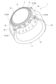
- FIG. 1 is a perspective view showing the configuration of a blood pressure measuring device according to an embodiment of the present invention.
- FIG. 2 is a partially cutaway side view of the blood pressure measuring device.
- FIG. 3 is a side view showing the configuration of a cuff structure used in the blood pressure measuring device.
- FIG. 4 is a perspective view showing the configuration of the cuff structure and the bag used in the blood pressure measuring device.
- FIG. 5 is a partially cutaway side view showing the structure of the bag and the cuff structure.
- FIG. 6 is a plan view showing the configuration of the cuff structure.
- FIG. 7 is a sectional view showing the configuration of the bag and the cuff structure.
- FIG. 8 is a sectional view showing the configuration of the bag and the cuff structure.
- FIG. 1 is a perspective view showing the configuration of a blood pressure measuring device according to an embodiment of the present invention.
- FIG. 2 is a partially cutaway side view of the blood pressure measuring device.
- FIG. 3 is
- FIG. 9 is an explanatory diagram showing a state in which the blood pressure measuring device is worn on the wrist.
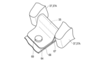
- FIG. 10 is an explanatory diagram showing the configuration of a mounting portion according to a modification of the present invention.
- FIG. 11 is an explanatory diagram showing a cuff structure according to a modification of the present invention.
- FIG. 1 is a perspective view showing the configuration of a blood pressure measuring device 1.
- FIG. 2 is a partially cutaway side view of the blood pressure measuring device 1.
- FIG. 2 shows a state in which the belt 4 used in the blood pressure measuring device 1 is cut.
- FIG. 3 is a side view showing the configuration of the cuff structure 6 used in the blood pressure measuring device 1.
- the cuff structure 6 is shown wrapped around the wrist 200.
- FIG. 4 is a perspective view showing the configuration of the belt 4 that accommodates the cuff structure 6.
- FIG. 5 is a partially cutaway side view showing the configuration of the belt 4 and cuff structure 6. As shown in FIG. Specifically, FIG. 5 shows a state in which the belt 4 is cut.
- FIG. 6 is a plan view showing the configuration of the cuff structure 6.
- FIG. 7 is a sectional view showing the configuration of the belt 4 and cuff structure 6. Specifically, FIG. 7 shows a state in which the belt 4 and the cuff structure 6 are cut along the width direction of the cuff structure 6 at a position passing through the pressing cuff 71, the back plate 72, and the sensing cuff 73.
- FIG. 8 is a sectional view showing the configuration of the belt 4 and cuff structure 6. Specifically, FIG. 8 shows a state in which the belt 4 and the cuff structure 6 are cut along the width direction at a position passing through the pressing cuff 71 and the first connecting portion 84.
- FIG. 9 is an explanatory diagram showing a state in which the blood pressure measuring device 1 is worn on the wrist.
- the blood pressure measurement device 1 is an electronic blood pressure measurement device that is attached to a living body. This embodiment will be described using an electronic blood pressure measuring device in the form of a wearable device attached to the wrist 200 of a living body.
- the blood pressure measuring device 1 includes a device main body 3, a belt 4 provided on the device main body 3 for wrapping the device main body 3 around a wrist 200, and a cuff structure housed in the belt 4. It is equipped with 6 and.
- the device main body 3 includes, for example, a case 11, a display section 12, and an operation section 13.
- the device main body 3 also includes a pump 14 for inflating the cuff structure 6, a flow path section for fluidly connecting the pump 14 and the cuff structure 6, and a control board within the case 11.
- the case 11 includes an outer case 31 and a windshield 32 that covers an opening of the outer case 31 on the side opposite to the wrist 200 side.
- the outer case 31 includes, for example, a case body 33 formed in a cylindrical shape, two pairs of lugs 37, a bottom wall portion 34 provided at one end of the case body 33, an attached portion 35, and a shaft portion 36. , is equipped with.
- the case body 33 is formed, for example, in a cylindrical shape.
- One pair of lugs 37 is provided at one symmetrical position in the circumferential direction of the outer peripheral surface of the case body 33.
- the other pair of lugs 37 are provided at the other symmetrical position in the circumferential direction of the outer peripheral surface of the case body 33.
- the pair of lugs 37 are arranged in the circumferential direction of the case body 33.
- One pair of lugs 37 are referred to as first lugs 37A, and the other pair of lugs 37 are referred to as second lugs 37B.
- the attached portion 35 is provided, for example, between the pair of first lugs 37A.
- a later-described attachment portion 64 of the belt 4 is attached to the attached portion 35 .
- the attached portion 35 is, for example, detachably attached to the pair of first lugs 37A.
- the attached portion 35 is, for example, a spring bar.
- the shaft portion 36 functions as a fulcrum on which a later-described bag body 63 of the belt 4 is folded back.
- the shaft portion 36 is configured such that the bag 63 can be folded back around one axis in the width direction of the bag 63, for example.
- the shaft portion 36 is configured to be parallel to a direction perpendicular to the direction in which the bag 63 is wrapped around the wrist 200.
- the shaft portion 36 is configured, for example, in a rod shape provided between a pair of second lugs 37B.
- the shaft portion 36 is, for example, a spring bar that is detachably attached to the pair of second lugs 37B.
- the bottom wall portion 34 is provided at the opening of the case body 33 on the wrist 200 side and covers the opening.
- the wrist 200 side refers to the wrist 200 side when the blood pressure measuring device 1 is attached to the wrist 200.
- the bottom wall portion 34 is an example of the case 11 on the wrist 200 side.
- a connected portion 38 is formed in the bottom wall portion 34 .
- Connected portion 38 is in fluid communication with pump 14 .
- a flow path that is continuous with the pump 14 is formed in the case 11, and the connected portion 38 constitutes a part of this flow path.
- the connected portion 38 is configured to be connectable to connecting portions 84 and 93, which will be described later, of the cuff structure 6.
- the cuff structure 6 includes, for example, two connecting portions 84 and 93, so two connected portions 38 are formed.
- One of the connected parts 38 is referred to as a first connected part 38A, and the other connected part 38 is referred to as a second connected part 38B.
- the first connected portion 38A is configured to have a shape into which the connecting portion 84 is inserted, for example.
- the first connected portion 38A is formed, for example, in the shape of a hole opening in the outer surface 34a of the bottom wall portion 34.
- the second connected portion 38B is configured to have a shape into which the connecting portion 94 is inserted, for example.
- the second connected portion 38B is formed, for example, in the shape of a hole opening in the outer surface 34a of the bottom wall portion 34.
- the windshield 32 is, for example, a circular glass plate.
- the display section 12 is arranged at a position facing the windshield 32. As shown in FIG. 1, the display section 12 is electrically connected to the control board.
- the display unit 12 is, for example, a liquid crystal display or an organic electroluminescent display.
- the display unit 12 displays various information including date and time, blood pressure values such as systolic blood pressure and diastolic blood pressure, and measurement results such as heart rate.
- the operation unit 13 is configured to be able to input instructions from the user.
- the operation unit 13 includes a plurality of buttons 41 provided on the case 11 and a sensor that detects the operation of the buttons 41.
- the buttons 41 For example, three buttons 41 are provided.
- the belt 4 includes a belt main body 61 and a fixing portion 62.
- the belt main body 61 includes a bag body 63 and a mounting portion 64.
- the bag body 63 has a bag shape that accommodates the cuff structure 6 therein, and is configured in a band shape to be wrapped around the wrist 200. Furthermore, the bag body 63 is configured such that the cuff structure 6 can be pressed against the wrist 200 while being wrapped around the wrist 200 and fixed by the fixing portion 62 . Furthermore, the bag body 63 is configured to be able to press the inflated cuff structure 6 against the wrist 200 during blood pressure measurement.
- the cuff structure 6 is configured to be inflated by air supplied from the pump 14, and the bag body 63 is configured in a bag shape that does not inhibit the expansion of the cuff structure 6.
- the bag 63 has a length that is folded back at the shaft portion 36 when the blood pressure measuring device 1 is attached to the wrist 200, and the internal dimension in the longitudinal direction of the bag 63 is the same as the circumferential direction of the cuff structure 6 ( length (longitudinal direction).
- the cuff structure 6 includes, for example, a pressing cuff 71, a back plate 72, and a sensing cuff 73.
- the length of the pressing cuff 71 is longer than the length of each of the back plate 72 and the sensing cuff 73.
- the internal dimensions of the bag body 63 in the longitudinal direction are set to be greater than or equal to the length of the pressure cuff 71 in the longitudinal direction.
- the internal dimension of the bag 63 in the lateral direction is set to be greater than or equal to the length of the cuff structure 6 in the lateral direction, and is, for example, approximately equal to the width of the cuff structure 6 in the lateral direction.
- the length of the pressing cuff 71 in the lateral direction is longer than the length of each of the back plate 72 and the sensing cuff 73 in the lateral direction. Therefore, the internal dimension of the bag body 63 in the lateral direction is approximately equal to the length of the pressure cuff 71 in the lateral direction.
- the internal dimension of the bag 63 in the thickness direction is set to a length that does not inhibit the inflation of the cuff structure 6.
- the internal dimension of the bag 63 in the thickness direction is set to a length that allows for expansion of the cuff structure 6.
- a hole 65 is formed at one end of the bag 63 in the longitudinal direction.
- the same number of holes 65 as the connecting parts 84 and 93 provided in the cuff structure 6 are formed.
- two connecting portions 84 and 93 are provided, two holes 65 are formed.
- One hole 65 is designated as a first hole 65A, and the other hole is designated as a second hole 65B.
- the first hole 65A is formed at a portion facing the first connecting portion 84 when the cuff structure 6 is housed in the bag body 63.
- the first connection portion 84 is disposed in the first hole 65A with the cuff structure 6 housed within the bag body 63.
- the second hole 65B is formed at a portion facing the second connecting portion 93 when the cuff structure 6 is accommodated in the bag body 63.
- the second connection portion 93 is disposed in the second hole 65B with the cuff structure 6 housed within the bag body 63.
- the bag body 63 configured in this way is made of cloth, for example.
- the attachment portion 64 is formed in a band shape, with one end facing the bag 63 and fixed to the other end of the bag 63 rather than the first hole 65A and the second hole 65B. The other end of the attachment portion 64 is attached to the attached portion 35 .
- the length from one end of the attachment part 64 to the attached part 35 is the length from one end of the attachment part 64 to the first connection part 84 when the cuff structure 6 is housed in the bag body 63. , and the length from one end of the attachment portion 64 to the second connection portion 93.
- the attachment part 64 includes, for example, an attachment part main body 66 formed in a band shape, a support part 67 that is provided on the attachment part main body 66 and is supported by the attached part 35 by arranging the attached part 35 inside. It is equipped with
- One end in the longitudinal direction of the attachment body 66 is fixed to the bag 63 in such a manner that the width direction of the attachment body 66 is parallel to the width direction of the bag 63.
- One end of the attachment main body 66 is fixed to the bag body 63, for example, from one end to the other end in the width direction.
- the attachment body 66 is configured to be rotatable around one axis parallel to the width direction of the attachment body 66.
- the attachment part main body 66 has flexibility, for example, and rotates around this one axis by bending around one axis parallel to the width direction of the attachment part main body 66.
- the mounting portion main body 66 configured in this way is made of cloth, for example.
- One end of the attachment main body 66 is fixed to the bag body 63, for example, by sewing.
- the support portion 67 is formed in a cylindrical shape with both ends open in the width direction of the attachment portion main body 66.
- the support portion 67 is configured such that a part of the attached portion 35 can be placed therein.
- the axial dimension of the support portion 67 is, for example, the same or approximately the same length as the length of the attached portion 35.
- the support portion 67 is configured to be rotatable relative to the attached portion 35.
- the support portion 67 has a size that allows it to rotate relative to the attached portion 35 disposed inside, for example.
- the support portion 67 is made of cloth, for example.
- the support portion 67 is fixed to the attachment portion main body 66 by, for example, sewing.
- the support portion 67 may be configured, for example, by folding back and fixing the end portion of the attachment portion main body 66.
- the fixing part 62 is configured to be able to fix the part of the bag 63 that is folded back and stacked on the shaft part 36.
- the fixing portion 62 is, for example, a hook-and-loop fastener.
- the fixing part 62 includes, for example, a hook part 62a provided with a plurality of hooks, and a loop part 62b provided with a plurality of loops.
- the hook portion 62a is provided at the other end of the bag body 63.
- the loop portion 102 is provided in a region of the bag 63 that faces the hook portion 62a when the bag 63 is tightened around the wrist 200.
- the hook part 62a and the loop part 62b of the fixing part 62 were each formed in different areas of the surface of the bag body 63, but the present invention is not limited to this.
- the fixing portion 62 may have a configuration in which a plurality of hooks and a plurality of loops are provided in a mixed manner within the same predetermined area.
- the belt 4 configured in this manner is formed into an annular shape together with the device body 3 as shown in FIG. Configure.
- the cuff structure 6 is housed within the belt 4, as shown in FIG. As shown in FIGS. 2, 3, and 5 to 8, the cuff structure 6 includes, for example, a pressing cuff 71, a back plate 72, and a sensing cuff 73.
- a back plate 72 is arranged on a pressing cuff 71, and a sensing cuff 73 is arranged on the back plate 72.
- adjacent components are fixed to each other by, for example, a bonding layer 75.
- the bonding layer 75 is made of, for example, adhesive or double-sided tape.
- the pressing cuff 71 is configured in a band shape extending in one direction. As shown in FIGS. 6 and 7, the pressure cuff 71 includes, for example, a plurality of air bags 81 and a first connecting portion 84 connected to the first connected portion 38A of the device main body 3. . The press cuff 71 is fluidly connected to the pump 14 by connecting the first connecting portion 84 to the first connected portion 38A.
- the plurality of air bags 81 is, for example, two air bags 81.
- Such a pressing cuff 71 is constructed by welding a plurality of sheet members 86 together.
- the air bag 81 is a bag-like structure, and in this embodiment, since the blood pressure measuring device 1 is configured to use air by a pump, an air bag will be used for explanation, but fluid other than air may be used.
- the bag-like structure may be a fluid bag that expands with the fluid.
- the plurality of air bags 81 are stacked and fluidly communicated in the stacking direction.
- the air bag 81 is formed into a rectangular bag shape that is long in one direction.
- the air bag 81 is constructed by, for example, combining two sheet members 86 and welding them by heat into a rectangular frame shape that is long in one direction, as shown in FIG. 6 with a welded portion 81a.
- the first connecting portion 84 is configured to project outward from the air bag 81, for example. Specifically, the first connecting portion 84 is provided on the air bag 81 facing the bottom wall portion 34 of the case 11 via the belt 4 . The tip of the first connecting portion 84 is exposed from the sheet member 86 on the device main body 3 side, of the two sheet members 86 forming the air bag 81 .
- the first connecting portion 84 is arranged in the first hole 65A of the bag body 63.
- the first connecting portion 84 is connected to the first connected portion 38A by being inserted into the first connected portion 38A, for example.
- the press cuff 71 is fluidly connected to the pump 14.
- the first connecting portion 84 and the first connected portion 38A are fixed so that the connection between the first connecting portion 84 and the first connected portion 38A is maintained during blood pressure measurement, and the blood pressure measuring device 1 is fixed to the wrist 200. It is only necessary that the first connecting part 84 is fixed so as to have a holding force that maintains the connection of the first connected part 38A even when the first connecting part 84 is detached from the first connected part 38A.
- the back plate 72 is formed into a plate shape that is long in one direction, as shown in FIGS. 5 and 6.
- the back plate 72 is attached to the outer surface of the first sheet member 86a of the pressure cuff 71 by a bonding layer 75.
- the back plate 72 conforms to the shape of the wrist 200 and transmits the pressing force from the pressing cuff 71 to the main surface of the sensing cuff 73 on the back plate 72 side.
- the back plate 72 has shape followability.
- shape followability refers to a function in which the back plate 72 can be deformed so as to follow the shape of the contact point of the wrist 200 that is placed, and the back plate 72 is opposed to the contact point of the wrist 200.
- Contact refers to the area of wrist 200, and contact here includes both direct contact and indirect contact via sensing cuff 73.
- the back plate 72 has a plurality of grooves 72a extending in a direction perpendicular to the longitudinal direction of the back plate 72 on both main surfaces of the back plate 72.
- the plurality of grooves 72a provided on both main surfaces face each other in the thickness direction of the back plate 72.
- the back plate 72 is designed to follow the shape of the wrist 200 because the part with the plurality of grooves 72a is thinner than the part without the grooves 72a, and the part with the plurality of grooves 72a is easily deformed. It deforms and has shape followability extending in the circumferential direction of the wrist 200.
- the sensing cuff 73 is fixed to the main surface of the back plate 72 on the wrist 200 side by a bonding layer 75.
- the length of the sensing cuff 73 in the longitudinal direction is set to a length that contacts a region where at least one of the radial artery 211 and the ulnar artery 212, which are the arteries 210 of the wrist 200, exists.
- the sensing cuff 73 is formed, for example, in the same shape as the back plate 72 or in a smaller shape than the back plate 72 in the longitudinal and width directions of the back plate 72. When inflated, the sensing cuff 73 presses the area on the palm side of the wrist 200 where the artery 210 exists. The sensing cuff 73 is pressed toward the wrist 200 via the back plate 72 by the inflated pressing cuff 71 .
- the sensing cuff 73 includes a second connecting portion 93, and is fluidly connected to the pump 14 by connecting the second connecting portion 93 to the second connected portion 38B.
- the sensing cuff 73 includes, for example, one air bag 91, a flow path body 92 communicating with the air bag 91, and a second connection provided at the tip of the flow path body 92. 93.
- one main surface of the air bag 91 is fixed to the back plate 72 by a bonding layer 75.
- the sensing cuff 73 is bonded to the main surface of the back plate 72 on the wrist 200 side by a bonding layer 75.
- Such a sensing cuff 73 is constructed by welding two sheet members 96 together.
- the air bag 91 is a bag-like structure, and in this embodiment, since the blood pressure measuring device 1 is configured to use air by a pump, the explanation will be made using an air bag.
- the bag-like structure may be a fluid bag that expands with the fluid.
- the air bag 91 is configured in a rectangular shape that is long in one direction.
- the air bag 91 is constructed, for example, by combining two sheet members 96 that are long in one direction and welded together by heat into a rectangular frame shape that is long in one direction, as shown in FIG. 7 with a welded portion 91a.
- the flow path body 92 is integrally provided in a part of one edge of the air bag 91 in the longitudinal direction.
- the channel body 92 is provided at the end of the air bag 91 near the device main body 3.
- the channel body 92 is formed in a shape that is elongated in one direction with a width smaller than the width in the transverse direction of the air bag 91, and has a circular tip.
- the channel body 92 has a second connection portion 93 at the tip.
- the flow path body 92 is connected to the flow path portion via the second connection portion 93, and forms a flow path between the flow path portion of the device main body 3 and the air bag 91.
- the flow path body 92 moves a part of the sheet member 96 adjacent to the region of the sheet member 96 constituting the air bag 91 in one direction. It is constructed by welding a long frame using heat.
- the air bag 91 has a structure in which a part of the welded part 91a where the two sheet members 96 are welded into a rectangular frame shape is not welded, and is continuous with the welded part 92a that constitutes the flow path body 92.
- the air bladder 91 and the channel body 92 are fluidly communicated.
- the second connecting portion 93 is configured to protrude outward from the air bag 91, for example.
- the second connecting portion 93 is provided at the tip of the channel body 92 . Further, the tip of the second connecting portion 93 is exposed to the outside from the sheet member 96 facing the back plate 72, of the two sheet members 96 forming the channel body 92.
- the second connecting portion 93 is arranged in the second hole 65B of the bag body 63.
- the second connecting portion 93 is connected to the second connected portion 38B by being inserted into the second connected portion 38B, for example.
- the sensing cuff 73 is fluidly connected to the pump 14.
- the fixation of the second connecting portion 93 and the second connected portion 38B is such that the connection between the second connecting portion 93 and the second connected portion 38B is maintained during blood pressure measurement, and the blood pressure measuring device 1 is held on the wrist. It is sufficient that the second connecting portion 93 has a holding force that maintains the connection of the second connected portion 38B even when the second connecting portion 93 is removed from the second connected portion 200.
- the cuff structure 6 configured in this manner has a configuration in which the second connection part 93 of the sensing cuff 73 is arranged on the first connection part 84 side of the pressing cuff 71 in the thickness direction of the cuff structure 6. ing.
- the pressure cuff 71 has an insertion portion 71a in which a part of the sensing cuff 73 is disposed, for example, at the mid-abdomen in the longitudinal direction of the pressure cuff 71.
- the insertion part 71a is configured, for example, in a shape in which a part of the edge along the longitudinal direction of the press cuff 71 is recessed in the lateral direction of the press cuff 71.
- the insertion portion 71a is configured to allow the channel body 92 of the sensing cuff 73 to pass from the inner peripheral surface side of the pressing cuff 71 to the device main body 3 side.
- the insertion portion 71a is not limited to a shape in which a part of the edge along the longitudinal direction of the pressure cuff 71 is recessed in the lateral direction of the pressure cuff 71.
- the insertion portion 71a may be a hole in which the second connection portion 93 can be placed.
- the channel body 92 may be configured to extend beyond the longitudinal edge of the press cuff 71 toward the first connecting portion 84 side.
- the user peels off the hook part 101 fixed to the loop part 102 from the loop part 102 and pulls out the bag 63 from between the shaft part 36 and the outer case 31 to remove the bag 63 and the device main body 3.
- the annular space is adjusted to a size that allows the wrist 200 to be inserted.
- the user inserts the wrist 200 into the annular space formed by the bag 63 and the device main body 3.
- the user moves the blood pressure measurement device 1 with respect to the wrist 200, so that the sensing cuff 73 faces the area of the wrist 200 where the artery exists.
- the user tightens the bag 63 by pulling the end of the bag 63 on the hook portion 101 side, for example, and presses the sensing cuff 73 against the region of the wrist 200 where the artery exists, and the hook portion 101 is attached to the loop portion 102. Fix it. Through such a procedure, the blood pressure measuring device 1 is attached to the wrist 200.
- the cuff structure 6 is housed in the bag body 63 of the belt body 61 of the belt 4.
- the bag body 63 does not inhibit the inflation of the cuff structure 6. Further, the bag body 63 presses the cuff structure 6 against the wrist 200 while being wrapped around the wrist 200 and fixed by the fixing portion 62 .
- the cuff structure 6 can be suitably pressed against the wrist 200. As a result, blood pressure measurement accuracy can be improved.
- the cuff structure 6 is fluidly connected to the pump 14 by connecting the connecting parts 84 and 93 and the connected parts 38A and 38B, and the attachment part 64 of the belt 4 is attached to the attached part 35 of the device main body 3.
- the connecting parts 84, 93 and the connected parts 38A, 38B need only have a holding force that maintains the fluid connection between the cuff structure 6 and the pump 14, and the cuff structure 6 can be A configuration for directly attaching to the device main body 3 is not required. Therefore, the configuration of the blood pressure measuring device 1 can be simplified.
- the connecting parts 84, 93 can be connected to the connected parts 38A, 38B by simply inserting the connecting parts 84, 93 and the connected parts 38A, 38B into the connected parts 38A, 38B. It is also possible to have a simple configuration.
- the length from one end of the attachment part 64 fixed to the bag body 63 to the attached part 35 is the length from the one end part of the attachment part 64 fixed to the bag body 63 to both of the connecting parts 84 and 93. shorter than length. Therefore, even if the bag 63 is pulled by the user when the blood pressure measuring device 1 is attached to the wrist 200, the tensile force does not act between one end of the bag 63 and one end of the attachment portion 64. Therefore, the connecting parts 84, 93 are not pressed by the edges of the holes 65A, 65B of the bag 63, so that the connecting parts 84, 93 are not pressed in the direction intersecting the direction in which the connecting parts 84, 93 protrude. Therefore, the connected parts 38A and 38B are not pressed.
- connecting portions 84 and 93 and the connected portions 38A and 38B are configured such that one is inserted into the other. Therefore, the connecting parts 84 and 93 can be easily connected to the connected parts 38A and 38B.
- the connected parts 38A and 38B are provided on the wrist 200 side of the case 11, when the blood pressure measuring device 1 is worn on the wrist 200, the connected parts 84 and 93 are connected to the connected part 38A and 38B by the wrist 200. Movement in the direction of exiting from 38B is restricted.
- the holding force for maintaining the state in which the connecting parts 84 and 93 are inserted into the connected parts 38A and 38B is such that when the blood pressure measuring device 1 is removed from the wrist 200, the connecting parts 84 and 93 are inserted into the connected parts 38A and 38B.
- the holding force may be sufficient to prevent 84 and 89 from coming off.
- the attachment main body 66 is flexible, the movable area of the belt 4 around the spring bar 35 can be increased. Therefore, it is easy to attach and detach the blood pressure measuring device 1 to the wrist 200.
- the length of the bag 63 along the circumferential direction of the wrist 200 can be adjusted steplessly in the blood pressure measuring device 1. .
- the blood pressure measuring device 1 As described above, according to the blood pressure measuring device 1 according to the present embodiment, it is possible to provide a blood pressure measuring device 1 that can prevent the blood pressure measurement accuracy from decreasing.
- the belt 4 of the blood pressure measuring device 1 is made of cloth, but the present invention is not limited to this. In other examples, the belt 4 may be made of resin.
- the attachment portion 64 may be configured to be detachably attached to the attached portion 35.
- the support portion 67 may be configured by, for example, folding back the end of the attachment portion body 66 on the device body 3 side and attaching the folded portion to the other portion of the attachment portion body 66, such as a button, etc. It may be configured by fixing with a detachable fixing part 69.
- a hook-and-loop fastener can be used instead of a button.
- the supporting part 67 configured in this way, when the belt 4 is removed by the main body 3 of the apparatus, by releasing the fixation by the detachable fixing part 69, the attached part 35 can be attached to the pair of first lugs. It becomes possible to remove the bag 63 from the device main body 3 without removing it from the bag 37A. Therefore, the efficiency of attaching and detaching the belt 4 to and from the apparatus main body 3 can be improved.
- the blood pressure measuring device 1 may be configured to further include a curler 5, as in a modification shown in FIG.
- the curler 5 is configured in a band shape that curves along the circumferential direction of the wrist 200 and has one end and the other end separated from each other.
- a cuff structure 6 is arranged on the inner peripheral surface of the curler 5.
- the curler 5 holds a part of the cuff structure 6 along the shape of the inner peripheral surface of the curler 5.
- the curler 5 is housed within the belt 4 of the belt 4.
- the curler 5 holds the cuff structure 6 by fixing the cuff structure 6 with a bonding layer provided between the curler 5 and the cuff structure 6.
- the curler 5 is formed with a hole in which the first connection part 84 is arranged and a hole in which the second connection part 93 is arranged.
- the curler 5 has flexibility and hardness that allows it to retain its shape.
- flexibility means that the shape of the curler 5 is deformed in the radial direction when an external force from the belt 4 is applied to the curler 5.
- flexibility means that when the curler 5 is pressed by the belt 4, the shape in side view is close to the wrist 200, follows the shape of the wrist 200, or follows the shape of the wrist 200. It means to transform.
- shape retention refers to the ability of the curler to maintain its pre-shaped shape when no external force is applied.
- shape retention means that the shape of the curler 5 can maintain a curved shape along the circumferential direction of the wrist 200.
- the connecting portions 84 and 93 are formed in a protruding shape that protrudes to the outside has been described as an example, but the present invention is not limited to this.
- the connected parts 38A, 38B formed in the device main body 3 are formed in a shape protruding from the bottom wall part 34, the connecting parts 84, 93 are formed in a hole shape, and the connected parts 38A, 38B are formed in a shape of a hole.
- the connecting portions 84, 93 and the connected portions 38A, 38B may be connected by being inserted into the connecting portions 84, 93.
- the belt 4 is folded back at the shaft portion 36 and fixed at the fixing portion 62, but the belt 4 is not limited to this.
- one belt member of a belt configured to include belt members fixed at circumferentially symmetrical positions on the outer circumferential surface of the device main body 3, and these belt members are connected to each other by, for example, a buckle.
- a bag body 63 and an attachment part 64 may be used.
- the connecting parts 84, 93 are configured in a protruding shape, and the connected parts 38A, 38B
- the configuration has been described as an example, the configuration is not limited to this.
- the connected parts 38A and 38B may be inserted into the connecting parts 84 and 93.
- the present invention is not limited to the above-described embodiments, and can be variously modified in the implementation stage without departing from the spirit thereof. Moreover, each embodiment may be implemented by appropriately combining them as much as possible, and in that case, the combined effects can be obtained. Further, the embodiments described above include inventions at various stages, and various inventions can be extracted by appropriately combining the plurality of disclosed constituent elements. For example, if a problem can be solved and an effect can be obtained even if some constituent features are deleted from all the constituent features shown in the embodiment, the configuration from which these constituent features are deleted can be extracted as an invention.
Landscapes
- Health & Medical Sciences (AREA)
- Life Sciences & Earth Sciences (AREA)
- Cardiology (AREA)
- Engineering & Computer Science (AREA)
- General Health & Medical Sciences (AREA)
- Veterinary Medicine (AREA)
- Biomedical Technology (AREA)
- Heart & Thoracic Surgery (AREA)
- Medical Informatics (AREA)
- Molecular Biology (AREA)
- Surgery (AREA)
- Animal Behavior & Ethology (AREA)
- Physics & Mathematics (AREA)
- Pathology (AREA)
- Public Health (AREA)
- Biophysics (AREA)
- Vascular Medicine (AREA)
- Physiology (AREA)
- Ophthalmology & Optometry (AREA)
- Dentistry (AREA)
- Signal Processing (AREA)
- Measuring Pulse, Heart Rate, Blood Pressure Or Blood Flow (AREA)
Priority Applications (3)
| Application Number | Priority Date | Filing Date | Title |
|---|---|---|---|
| DE112023001615.1T DE112023001615T5 (de) | 2022-03-29 | 2023-03-09 | Blutdruckmessvorrichtung |
| CN202380013108.1A CN117794444A (zh) | 2022-03-29 | 2023-03-09 | 血压测定装置 |
| US18/442,579 US20240180437A1 (en) | 2022-03-29 | 2024-02-15 | Blood pressure measurement device |
Applications Claiming Priority (2)
| Application Number | Priority Date | Filing Date | Title |
|---|---|---|---|
| JP2022053720A JP7757855B2 (ja) | 2022-03-29 | 2022-03-29 | 血圧測定装置 |
| JP2022-053720 | 2022-03-29 |
Related Child Applications (1)
| Application Number | Title | Priority Date | Filing Date |
|---|---|---|---|
| US18/442,579 Continuation US20240180437A1 (en) | 2022-03-29 | 2024-02-15 | Blood pressure measurement device |
Publications (1)
| Publication Number | Publication Date |
|---|---|
| WO2023189373A1 true WO2023189373A1 (ja) | 2023-10-05 |
Family
ID=88200647
Family Applications (1)
| Application Number | Title | Priority Date | Filing Date |
|---|---|---|---|
| PCT/JP2023/009120 Ceased WO2023189373A1 (ja) | 2022-03-29 | 2023-03-09 | 血圧測定装置 |
Country Status (5)
| Country | Link |
|---|---|
| US (1) | US20240180437A1 (https=) |
| JP (1) | JP7757855B2 (https=) |
| CN (1) | CN117794444A (https=) |
| DE (1) | DE112023001615T5 (https=) |
| WO (1) | WO2023189373A1 (https=) |
Citations (4)
| Publication number | Priority date | Publication date | Assignee | Title |
|---|---|---|---|---|
| JP2013192879A (ja) * | 2012-03-22 | 2013-09-30 | Citizen Holdings Co Ltd | 血圧計 |
| CN109044310A (zh) * | 2018-09-07 | 2018-12-21 | 深圳金亿帝医疗设备股份有限公司 | 气囊、手表式血压计、便携式血压模块以及生命体征监护仪 |
| JP2020092885A (ja) * | 2018-12-13 | 2020-06-18 | オムロン株式会社 | 血圧測定装置 |
| JP2021107000A (ja) * | 2015-10-08 | 2021-07-29 | チャームケア・カンパニー・リミテッド | 手首血圧計 |
Family Cites Families (16)
| Publication number | Priority date | Publication date | Assignee | Title |
|---|---|---|---|---|
| JPH0611701U (ja) * | 1991-07-31 | 1994-02-15 | 株式会社シグナルテクノロジー | 腕時計血圧測定器 |
| US6344025B1 (en) * | 1999-02-19 | 2002-02-05 | Omron Corporation | Blood pressure monitor |
| JP4614250B2 (ja) * | 2000-11-27 | 2011-01-19 | セイコーインスツル株式会社 | 装着形計測機器 |
| JP4595525B2 (ja) * | 2004-12-20 | 2010-12-08 | オムロンヘルスケア株式会社 | 血圧計用カフおよびこれを備えた血圧計 |
| KR101068116B1 (ko) | 2008-05-23 | 2011-09-27 | (주)한별메디텍 | 비침습적 연속 혈압 및 동맥 탄성도 측정을 위한 요골 맥파센싱 장치 및 방법 |
| WO2016205549A1 (en) * | 2015-06-16 | 2016-12-22 | Braintree Analytics Llc | Cuff designs and methods |
| JP6172341B2 (ja) * | 2016-01-04 | 2017-08-02 | オムロンヘルスケア株式会社 | 生体情報測定装置 |
| CN105686817A (zh) * | 2016-03-29 | 2016-06-22 | 深圳金亿帝医疗设备股份有限公司 | 血压计袖带和手表式电子血压计 |
| TWI656862B (zh) * | 2016-12-01 | 2019-04-21 | 國立台灣大學 | 單臂式微型氣壓泵裝置 |
| CN206964182U (zh) * | 2017-03-24 | 2018-02-06 | 吴田 | 一种可调节传感器位置的表带结构 |
| CN208677378U (zh) * | 2017-08-07 | 2019-04-02 | 深圳邦普医疗设备系统有限公司 | 一种血压腕表的表带 |
| JP7175720B2 (ja) * | 2018-11-09 | 2022-11-21 | オムロン株式会社 | 血圧測定装置 |
| JP7202886B2 (ja) * | 2018-12-27 | 2023-01-12 | オムロンヘルスケア株式会社 | 血圧測定装置 |
| JP7150595B2 (ja) * | 2018-12-27 | 2022-10-11 | オムロンヘルスケア株式会社 | 血圧測定装置用カフカバー |
| CN115429243B (zh) * | 2019-11-25 | 2025-08-08 | 华为技术有限公司 | 一种血压测量手表 |
| JP7472557B2 (ja) | 2020-03-12 | 2024-04-23 | オムロンヘルスケア株式会社 | カフ構造体、及び血圧測定装置 |
-
2022
- 2022-03-29 JP JP2022053720A patent/JP7757855B2/ja active Active
-
2023
- 2023-03-09 DE DE112023001615.1T patent/DE112023001615T5/de active Pending
- 2023-03-09 WO PCT/JP2023/009120 patent/WO2023189373A1/ja not_active Ceased
- 2023-03-09 CN CN202380013108.1A patent/CN117794444A/zh active Pending
-
2024
- 2024-02-15 US US18/442,579 patent/US20240180437A1/en active Pending
Patent Citations (4)
| Publication number | Priority date | Publication date | Assignee | Title |
|---|---|---|---|---|
| JP2013192879A (ja) * | 2012-03-22 | 2013-09-30 | Citizen Holdings Co Ltd | 血圧計 |
| JP2021107000A (ja) * | 2015-10-08 | 2021-07-29 | チャームケア・カンパニー・リミテッド | 手首血圧計 |
| CN109044310A (zh) * | 2018-09-07 | 2018-12-21 | 深圳金亿帝医疗设备股份有限公司 | 气囊、手表式血压计、便携式血压模块以及生命体征监护仪 |
| JP2020092885A (ja) * | 2018-12-13 | 2020-06-18 | オムロン株式会社 | 血圧測定装置 |
Also Published As
| Publication number | Publication date |
|---|---|
| JP7757855B2 (ja) | 2025-10-22 |
| US20240180437A1 (en) | 2024-06-06 |
| JP2023146511A (ja) | 2023-10-12 |
| CN117794444A (zh) | 2024-03-29 |
| DE112023001615T5 (de) | 2025-04-03 |
Similar Documents
| Publication | Publication Date | Title |
|---|---|---|
| CN107635462A (zh) | 生物体信息测量装置 | |
| CN115066202B (zh) | 袖带构造体以及血压测定装置 | |
| US10022056B2 (en) | Blood pressure measurement cuff and attachment method for the same | |
| CN102770065B (zh) | 血压信息测定装置用袖带及具有该袖带的血压信息测定装置 | |
| JP2007275483A (ja) | 血圧計用カフ | |
| WO2023189373A1 (ja) | 血圧測定装置 | |
| KR200252753Y1 (ko) | 혈압계용 압박대 | |
| US20240041337A1 (en) | Blood pressure measurement device | |
| JP7556200B2 (ja) | カフ構造体、及び、血圧測定装置 | |
| JP2669858B2 (ja) | 手首用血圧計 | |
| JP2023146522A (ja) | 血圧測定装置 | |
| JP2013034791A (ja) | 血圧計用カフ | |
| CN117999028A (zh) | 生物信息测量装置 | |
| JP2021142148A (ja) | カフ構造体、及び血圧測定装置 | |
| JP2023146511A5 (https=) | ||
| JPH02299635A (ja) | 手首用血圧計のカフ帯 | |
| JP6139871B2 (ja) | 血圧計用カフ | |
| JPH0234144A (ja) | 血圧計のカフ帯 |
Legal Events
| Date | Code | Title | Description |
|---|---|---|---|
| 121 | Ep: the epo has been informed by wipo that ep was designated in this application |
Ref document number: 23779399 Country of ref document: EP Kind code of ref document: A1 |
|
| WWE | Wipo information: entry into national phase |
Ref document number: 202417004711 Country of ref document: IN |
|
| WWE | Wipo information: entry into national phase |
Ref document number: 202380013108.1 Country of ref document: CN |
|
| WWE | Wipo information: entry into national phase |
Ref document number: 112023001615 Country of ref document: DE |
|
| 122 | Ep: pct application non-entry in european phase |
Ref document number: 23779399 Country of ref document: EP Kind code of ref document: A1 |
|
| WWP | Wipo information: published in national office |
Ref document number: 112023001615 Country of ref document: DE |