WO2023189285A1 - 回転子及び電動機 - Google Patents
回転子及び電動機 Download PDFInfo
- Publication number
- WO2023189285A1 WO2023189285A1 PCT/JP2023/008571 JP2023008571W WO2023189285A1 WO 2023189285 A1 WO2023189285 A1 WO 2023189285A1 JP 2023008571 W JP2023008571 W JP 2023008571W WO 2023189285 A1 WO2023189285 A1 WO 2023189285A1
- Authority
- WO
- WIPO (PCT)
- Prior art keywords
- magnet
- rotor
- hole
- rotor core
- placement hole
- Prior art date
Links
- 239000000853 adhesive Substances 0.000 claims description 25
- 230000001070 adhesive effect Effects 0.000 claims description 25
- 229910000831 Steel Inorganic materials 0.000 claims description 8
- 239000010959 steel Substances 0.000 claims description 8
- 239000012790 adhesive layer Substances 0.000 description 18
- 238000010586 diagram Methods 0.000 description 5
- 238000003780 insertion Methods 0.000 description 4
- 230000037431 insertion Effects 0.000 description 4
- 238000004519 manufacturing process Methods 0.000 description 3
- 238000012986 modification Methods 0.000 description 3
- 230000004048 modification Effects 0.000 description 3
- 230000004907 flux Effects 0.000 description 2
- 238000000034 method Methods 0.000 description 2
- 229910001172 neodymium magnet Inorganic materials 0.000 description 2
- 239000000843 powder Substances 0.000 description 2
- KPLQYGBQNPPQGA-UHFFFAOYSA-N cobalt samarium Chemical compound [Co].[Sm] KPLQYGBQNPPQGA-UHFFFAOYSA-N 0.000 description 1
- 239000004020 conductor Substances 0.000 description 1
- 230000000694 effects Effects 0.000 description 1
- 239000003822 epoxy resin Substances 0.000 description 1
- 239000000696 magnetic material Substances 0.000 description 1
- 239000000463 material Substances 0.000 description 1
- 238000000465 moulding Methods 0.000 description 1
- 230000002093 peripheral effect Effects 0.000 description 1
- 229920000647 polyepoxide Polymers 0.000 description 1
- 238000004080 punching Methods 0.000 description 1
- 229920005989 resin Polymers 0.000 description 1
- 239000011347 resin Substances 0.000 description 1
- 229910000938 samarium–cobalt magnet Inorganic materials 0.000 description 1
- 229920002050 silicone resin Polymers 0.000 description 1
- 229920001187 thermosetting polymer Polymers 0.000 description 1
- 238000004804 winding Methods 0.000 description 1
Images


Classifications
-
- H—ELECTRICITY
- H02—GENERATION; CONVERSION OR DISTRIBUTION OF ELECTRIC POWER
- H02K—DYNAMO-ELECTRIC MACHINES
- H02K1/00—Details of the magnetic circuit
- H02K1/06—Details of the magnetic circuit characterised by the shape, form or construction
- H02K1/22—Rotating parts of the magnetic circuit
- H02K1/27—Rotor cores with permanent magnets
- H02K1/2706—Inner rotors
- H02K1/272—Inner rotors the magnetisation axis of the magnets being perpendicular to the rotor axis
- H02K1/274—Inner rotors the magnetisation axis of the magnets being perpendicular to the rotor axis the rotor consisting of two or more circumferentially positioned magnets
- H02K1/2753—Inner rotors the magnetisation axis of the magnets being perpendicular to the rotor axis the rotor consisting of two or more circumferentially positioned magnets the rotor consisting of magnets or groups of magnets arranged with alternating polarity
- H02K1/276—Magnets embedded in the magnetic core, e.g. interior permanent magnets [IPM]
Definitions
- the present disclosure relates to a rotor and an electric motor, and particularly relates to a rotor including a permanent magnet and an electric motor including the rotor.
- Patent Document 1 discloses a method for positioning magnets of a rotor of an electric motor.
- a rotor core divided in the direction of the rotation axis is prepared, a permanent magnet and adhesive are inserted into the magnet insertion hole, and the permanent magnet is positioned within the magnet insertion hole by twisting the divided rotor core in the rotation direction.
- Patent Document 1 when the divided rotor core is twisted in the rotational direction, the permanent magnet moves together with the adhesive within the magnet insertion hole, so that the corner portion hits the wall of the magnet insertion hole, resulting in line contact instead of surface contact. It becomes easier. If the contact area between both members is reduced in this manner, the rotor core is deformed during high-speed rotation, which causes torque ripple, thereby reducing the magnetic flux that can be taken out.
- the present disclosure has been made in view of the above points, and an object of the present disclosure is to provide a rotor and an electric motor that can hold permanent magnets in an appropriate posture.
- a rotor includes a rotating shaft, a first rotor core, a second rotor core, and a permanent magnet.
- the rotating shaft has an axial center as its center of rotation.
- the first rotor core is fixed to the rotating shaft and has a first magnet placement hole formed therein.
- the second rotor core is aligned with the first rotor core in the axial direction of the rotary shaft and is fixed to the rotary shaft, and has a second magnet placement hole corresponding to the first magnet placement hole. It is formed.
- the permanent magnet is arranged in a set of the first magnet arrangement hole and the second magnet arrangement hole.
- the positions of the first magnet arrangement hole and the second magnet arrangement hole are shifted from each other in the circumferential direction perpendicular to the axial direction of the rotating shaft, so that the permanent magnet is located between the first magnet arrangement hole and the second magnet arrangement hole. 2 is positioned within the magnet placement hole.
- An electric motor includes the rotor and stator.
- the permanent magnets can be held in an appropriate posture.
- FIG. 1 is a schematic top view of an electric motor according to an embodiment.
- FIG. 2 is a perspective view of the rotor according to the embodiment.
- FIG. 3 is a partially enlarged view of FIG. 1, and is a diagram showing the positional relationship between the first magnet placement hole and the second magnet placement hole.
- FIG. 4 is a partial cross-sectional view of the rotor according to the embodiment.
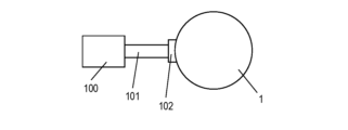
- FIG. 5 is a schematic diagram of an electric motor and a power source that supplies current to the electric motor according to the embodiment.
- FIG. 6 is a partial sectional view of a rotor according to a modification of the embodiment.
- the electric motor 1 is an inner rotor type motor.
- FIG. 1 is a schematic top view of an electric motor 1 according to an embodiment.
- FIG. 2 is a perspective view of the rotor 3 according to the embodiment.
- FIG. 3 is a partially enlarged view of FIG. 1, and is a diagram showing the positional relationship between the first magnet placement hole 13 and the second magnet placement hole 18.
- the electric motor 1 has a stator 2 and a rotor 3.
- the direction in which the axis 14 (described later) of the rotating shaft 10 (described later) extends is referred to as an axial direction A1
- the circumferential direction of the rotor 3 is referred to as a circumferential direction C1.
- a direction along a line segment connecting a point on a plane perpendicular to the axis 14 and an intersection of the plane and the axis 14 is referred to as a radial direction F1.
- the axial direction A1, the circumferential direction C1, and the radial direction F1 are orthogonal to each other.
- the stator 2 includes a stator core 4 and a plurality of (nine in FIG. 1) coils 6.
- the stator core 4 is a laminated core in which a plurality of electromagnetic steel plates are laminated in the thickness direction.
- the stator core 4 is formed into a substantially cylindrical column shape.
- the stator core 4 includes an annular core back 7 and a plurality of (nine teeth in FIG. 1) teeth 8.
- the plurality of teeth 8 are arranged on the inner peripheral surface of the core back 7 at regular intervals along the circumferential direction C1, and extend toward the axial center 14 in the radial direction F1.
- the plurality of coils 6 correspond to the plurality of teeth 8, and each coil 6 is formed by winding a conductor around the corresponding tooth 8.
- the rotor 3 is an IPM (Interior Permanent Magnet) type rotor in which a permanent magnet is embedded inside the rotor core.
- the rotor 3 is arranged in the radial direction F1 of the stator 2 and toward the axis 14, and includes a rotor core 9, a rotating shaft 10, and a plurality of (10 in FIG. 1) permanent magnets 11. .
- FIG. 5 shows a schematic diagram of a power supply 100 that supplies current to the electric motor 1.
- the electric motor 1 operates as follows.
- a cable 101 extends from a power supply 100 to the electric motor 1, and current is supplied through a power supply connection part 102. More specifically, three-phase currents having a phase difference of 120 degrees in electrical angle are supplied to the plurality of coils 6 through the power supply connection part 102, the stator 2 is excited, and a rotating magnetic field is generated.
- This rotating magnetic field interacts with the magnetic field generated by the permanent magnet 11 provided on the rotor 3 to generate rotational torque in the rotor 3, and as a result, the rotor 3 rotates around the axis 14. .
- FIG. 4 is a partial sectional view of the rotor 3 according to the embodiment.
- FIG. 4 is a cross-sectional view taken along a plane passing through the rotor core 9 and the permanent magnets 11, including the line IV-IV perpendicular to the radial direction F1, and along the circumferential direction C1 in FIG. Note that the IV-IV line segment is also shown in FIG.
- the rotor core 9 includes a first rotor core 21 and a second rotor core 22, which are divided in the axial direction A1 of the rotating shaft 10.
- Each of the first rotor core 21 and the second rotor core 22 is a laminated core in which a plurality of electromagnetic steel plates 17 are laminated in the thickness direction.
- Each of the first rotor core 21 and the second rotor core 22 has a circular center shaft hole 12 and is formed into a cylindrical shape.
- the first rotor core 21 and the second rotor core 22 have the same thickness in the axial direction A1, and the second rotor core 22 is arranged below the first rotor core 21 in the axial direction A1. There is.
- a plurality of first magnet arrangement holes 13 arranged in the circumferential direction C1 are formed in the first rotor core 21.
- the first magnet arrangement hole 13 has a substantially rectangular opening shape, and specifically, the longitudinal direction extends in the radial direction. In this embodiment, the first magnet arrangement hole 13 penetrates in the axial direction A1.
- a plurality of second magnet arrangement holes 18 are formed in the second rotor core 22 and arranged in the circumferential direction C1.
- the second magnet arrangement hole 18 has a substantially rectangular opening shape, and specifically, the longitudinal direction extends in the radial direction.
- the second magnet arrangement hole 18 has the same size, shape, radial and circumferential position, and arrangement interval in the circumferential direction C1 as the first magnet arrangement hole 13.
- the first rotor core 21 and the second rotor core 22 are stacked such that the first magnet placement hole 13 and the second magnet placement hole 18 overlap.
- the second magnet arrangement hole 18 penetrates in the axial direction A1.
- the rotating shaft 10 is a cylindrical member and has an axis 14 that is the center of rotation.
- the rotating shaft 10 is inserted into the central shaft hole 12 of the first rotor core 21 and the second rotor core 22 and is fixed therein.
- Each of the plurality of (10 in FIG. 1) permanent magnets 11 is arranged and fixed in a corresponding one of the plurality of first magnet arrangement holes 13 and second magnet arrangement holes 18 of the rotor core 9. .
- Each permanent magnet 11 has, for example, a rectangular parallelepiped shape. The cross-sectional area of the permanent magnet 11 is smaller than the opening area of the first magnet placement hole 13 and the second magnet placement hole 18 .
- a samarium-cobalt permanent magnet, a neodymium magnet, or the like can be used as the permanent magnet 11, Neodymium magnets are suitable for use in automobile motors.
- the positions of the first magnet arrangement hole 13 and the second magnet arrangement hole 18 are slightly shifted in the circumferential direction C1, as shown in FIGS. 3 and 4. Specifically, the second magnet arrangement hole 18 is offset from the first magnet arrangement hole 13 in the counterclockwise direction in the circumferential direction C1 in the plane of the paper of FIG.
- the permanent magnets 11 are arranged in the first magnet arrangement hole 13 and the second magnet arrangement hole 18 so as to be located on average at the center in the circumferential direction.
- the above configuration will be explained in detail below.
- the clockwise direction along the circumferential direction C1 is simply referred to as the "clockwise direction”
- the counterclockwise direction along the circumferential direction C1 is referred to as "clockwise direction”.
- the permanent magnet 11 is in contact with the first inner surface 131 (the counterclockwise side surface in the circumferential direction C1) of the first magnet placement hole 13 of the first rotor core 21, and , is in contact with the third inner surface 181 (clockwise side surface in the circumferential direction C1) of the second magnet arrangement hole 18 of the second rotor core 22.
- the permanent magnets 11 are inserted into the first magnet arrangement holes 13 of the first rotor core 21 from both sides of the circumferential direction C1 (clockwise side of the circumferential direction C1 and counterclockwise side of the circumferential direction C1). Then, it comes into contact with the second magnet arrangement hole 18 of the second rotor core 22 and is positioned within the first magnet arrangement hole 13 and the second magnet arrangement hole 18 .
- the permanent magnet 11 has a first side surface 111 and a second side surface 112, as shown in FIGS. 3 and 4.
- the first side surface 111 and the second side surface 112 face opposite sides in the circumferential direction C1.
- the upper portion 111A of the first side surface 111 is in contact with the first inner surface 131 of the first magnet placement hole 13.
- the lower portion 111B of the first side surface 111 has a fourth inner surface 182 of the first magnet arrangement hole 13 (the fourth inner surface 182 is recessed counterclockwise in the circumferential direction C1 when viewed from the first inner surface 131).
- the first gap 31 is provided between the first gap 31 and the first gap 31 .
- the lower portion 112B of the second side surface 112 includes a third inner surface 181 of the second magnet arrangement hole 18 (the third inner surface 181 protrudes counterclockwise in the circumferential direction C1 when viewed from the second inner surface 132). ) is in contact with the The upper portion 112A of the second side surface 112 is the second inner surface 132 of the second magnet arrangement hole 18 (the second inner surface 132 is recessed in the circumferential direction C1 counterclockwise when viewed from the third inner surface 181). They are arranged with a second gap 32 between them.
- the rotor 3 has a first adhesive layer 25 and a second adhesive layer 26 for fixing the permanent magnets 11 to the first magnet placement hole 13 and the second magnet placement hole 18.
- the first adhesive layer 25 and the second adhesive layer 26 are, for example, adhesives made of thermosetting resin, and specifically may be epoxy resin or silicone resin.
- the first adhesive layer 25 is arranged in the second gap 32, and the second adhesive layer 26 is arranged in the first gap 31. Note that between the upper portion 111A of the first side surface 111 and the first inner surface 131 of the first magnet placement hole 13, and between the lower portion 112B of the second side surface 112 and the third inner surface 181 of the second magnet placement hole 18, No adhesive is placed between them.
- the permanent magnet 11 is arranged in the first magnet arrangement hole 13 and the second magnet arrangement hole 18 so as to be parallel to the axial direction A1.
- parallel here means that the longitudinal axis of the permanent magnet 11 is parallel to the axial direction A1, and includes, for example, an inclination of 5 degrees or less.
- parallel here means that the longitudinal axis of the permanent magnet 11 is completely parallel to the axial direction A1 (the angle between the longitudinal axis of the permanent magnet 11 and the axial direction A1 is 0 degrees). ) and cases where the angle between the longitudinal axis of the permanent magnet 11 and the axial direction A1 is 5 degrees or less.
- the upper portion 111A of the first side surface 111 and the first inner side surface 131 of the first magnet placement hole 13 are in surface contact.
- the lower portion 112B of the second side surface 112 and the third inner side surface 181 of the second magnet placement hole 18 are in surface contact.
- surface contact refers to a relationship in which the surfaces are in contact with or close to each other and support each other.
- Rotor manufacturing method A manufacturing method of the rotor 3 will be explained. Note that the manufacturing method described below is an example and does not limit the present disclosure.
- a first rotor core 21 and a second rotor core 22 are prepared. Specifically, a plurality of electromagnetic steel plates 17 are formed by punching out an original electromagnetic steel plate using a press machine, and then the electromagnetic steel plates 17 are laminated to produce the first rotor core 21 and the second rotor core 22. do.
- the permanent magnets 11 are inserted into each set of the first magnet arrangement hole 13 and the second magnet arrangement hole 18 in the stacked first rotor core 21 and second rotor core 22. At this time, the first magnet arrangement hole 13 and the second magnet arrangement hole 18 are aligned with each other.
- the first rotor core 21 and the second rotor core 22 are rotated relative to each other in the circumferential direction C1.
- the upper portion 111A of the first side surface 111 of the permanent magnet 11 comes into surface contact with the first inner side surface 131 of the first magnet placement hole 13 in the circumferential direction C1.
- the lower portion 112B of the second side surface 112 of the permanent magnet 11 makes surface contact with the third inner side surface 181 of the second magnet placement hole 18 in the circumferential direction C1.
- the permanent magnets 11 are fixed to the rotor core 9 by applying the second adhesive layer 26 and the first adhesive layer 25 to the first gap 31 and the second gap 32, respectively.
- the rotating shaft 10 is attached to the first rotor core 21 and the second rotor core 22. Specifically, the rotating shaft 10 is fixed to the center shaft hole 12 of the first rotor core 21 and the second rotor core 22.
- FIG. 6 is a partial sectional view of the rotor 3 according to a modification of the embodiment. At least a portion between the upper part 111A of the first side surface 111 and the first inner surface 131 of the first magnet arrangement hole 13, and the lower part 112B of the second side surface 112 and the third inner part of the second magnet arrangement hole 18.
- the third adhesive layer 27 and the fourth adhesive layer 28 may be arranged at least in part between the side surface 181 and the side surface 181 .
- the amount of adhesive in the third adhesive layer 27 and the fourth adhesive layer 28 is smaller than that in the first adhesive layer 25 and the second adhesive layer 26, respectively.
- the structure of the permanent magnet, the first magnet arrangement hole, and the second magnet arrangement hole described above was realized in all the sets of the first magnet arrangement hole and the second magnet arrangement hole, but the above structure It may be realized only in some sets of the arrangement hole and the second magnet arrangement hole.
- the thickness in the axial direction of the first rotor core and the second rotor core may be different.
- the rotor core may be divided into three or more parts in the axial direction.
- the adhesive may be omitted.
- the shape, number, and position of the magnet placement holes and permanent magnets are not limited.
- the permanent magnet may have a rectangular shape with a short radial length in plan view.
- the rotor core may be a powder core whose main component is a powder material formed by pressure-molding a powdered magnetic material.
- the rotor (3) includes a rotating shaft (10), a first rotor core (21), and a second rotor core (22).
- the rotating shaft (10) rotates around the axial center (14).
- the first rotor core (21) is fixed to the rotating shaft (10), and has a first magnet placement hole (13) formed therein.
- the second rotor core (22) is fixed to the rotary shaft (10) in line with the first rotor core (21) in the axial direction of the rotary shaft (10), and is fixed to the first magnet arrangement hole (13).
- ) is formed with a second magnet arrangement hole (18) corresponding to the second magnet arrangement hole (18).
- the permanent magnet (11) is arranged in a set of a first magnet arrangement hole (13) and a second magnet arrangement hole (18).
- the permanent magnet (11) are positioned within the first magnet placement hole (13) and the second magnet placement hole (18).
- the permanent magnet (11) can be positioned within the set of the first magnet placement hole (13) and the second magnet placement hole (18).
- the rotor (3) according to the second aspect of the present disclosure has an adhesive (25) that fixes the permanent magnet (11) to the first magnet placement hole (13) and the second magnet placement hole (18). , 26).
- the permanent magnet (11) can be fixed within the set of the first magnet placement hole (13) and the second magnet placement hole (18) using the adhesive (25, 26).
- the permanent magnet (11) is connected to the first inner surface (131) of the first magnet arrangement hole (13) in the circumferential direction (C1).
- a first side surface (111, 111A) that is close to or in contact with each other, and a second side surface that is arranged with a gap (32) from the second inner surface (132) of the first magnet placement hole (13) in the circumferential direction (C1). (112, 112A).
- the adhesive (25, 26) has a first adhesive (25) disposed in at least a portion of the gap (32).
- the adhesive by disposing the adhesive (25) in the gap (32), the adhesive can be brought into contact with the members on both sides over a large area.
- the adhesive is applied to the first side surface (111A) of the permanent magnet (11) and the first inner surface of the first magnet placement hole (13). (131).
- the amount of adhesive used can be reduced.
- the first side surface (111, 111A) of the permanent magnet (11) is the first inner surface ( 131).
- the amount of adhesive is smaller than the first adhesive (25), and the amount of adhesive is between the first side surface (111, 111A) of the permanent magnet (11) and the first inner surface (131) of the first magnet placement hole (13). It further includes a second adhesive disposed at least partially in between.
- the permanent magnet (11) can be firmly fixed in the first magnet placement hole (13).
- the second side surface (112, 112B) of the permanent magnet (11) is arranged in the circumferential direction (C1). Close to or in contact with the third inner surface (181) of the second magnet arrangement hole (18).
- the first side surface (111, 111B) of the permanent magnet (11) is arranged with a gap (31) from the fourth inner surface (182) of the second magnet arrangement hole (18) in the circumferential direction (C1). .
- the permanent magnet (11) is supported by the first magnet placement hole (13) and the second magnet placement hole (18) on both sides in the circumferential direction. Moreover, the permanent magnet (11) secures a gap with respect to the first magnet arrangement hole (13) and the second magnet arrangement hole (18) on both sides in the circumferential direction.
- the first side surface (111, 111A) of the permanent magnet (11) is arranged such that the first magnet arrangement hole ( It is in surface contact with the first inner surface (131) of 13).
- the attitude of the permanent magnet (11) is stabilized.
- the permanent magnet (11) is arranged in the first magnet so as to be parallel to the axial direction. It is arranged in the hole (13) and the second magnet arrangement hole (18).
- the attitude of the permanent magnet (11) is stabilized.
- At least one of the first rotor core (21) and the second rotor core (22) includes: It consists of a plurality of laminated electromagnetic steel sheets (17).
- the first rotor core (21) and the second rotor core (22) can be manufactured relatively inexpensively.
- the first rotor core (21) has a plurality of first magnet placement holes (13).
- the second rotor core (22) has a plurality of second magnet placement holes (18).
- the plurality of first magnet arrangement holes (13) are lined up in the circumferential direction (C1) of the first rotor core (21).
- the plurality of second magnet arrangement holes (18) are lined up in the circumferential direction (C1) of the second rotor core, and correspond to the plurality of first magnet arrangement holes (13), respectively.
- the positioning of the plurality of permanent magnets (11) is performed simultaneously.
- An electric motor (1) according to an eleventh aspect of the present disclosure includes a rotor (3) and a stator (4) according to any one of the first to tenth aspects.
- the attitude of the permanent magnet (11) in the rotor (3) is stabilized.
- the permanent magnets included in the rotor can be held in an appropriate posture. Therefore, the rotor core can be prevented from being deformed during high-speed rotation of the rotor, thereby minimizing the generation of torque ripple and suppressing a decrease in the magnetic flux that can be taken out.
- the rotor and electric motor of the present disclosure are industrially useful.
Landscapes
- Engineering & Computer Science (AREA)
- Power Engineering (AREA)
- Permanent Field Magnets Of Synchronous Machinery (AREA)
Abstract
永久磁石の位置や姿勢を向上できる回転子及び電動機を提供する。回転子(3)では、第1回転子鉄心(21)は、回転軸に固定され、第1磁石配置穴(13)が形成されている。第2回転子鉄心(22)は、回転軸の軸心方向(A1)において第1回転子鉄心(21)と並んでかつ回転軸に固定されており、第1磁石配置穴(13)に対応する第2磁石配置穴(18)が形成されている。永久磁石(11)は、第1磁石配置穴(13)と第2磁石配置穴(18)の組に配置されている。第1磁石配置穴(13)と第2磁石配置穴(18)の位置が回転軸の軸心方向(A1)と直交する周方向(C1)に互いにずれていることにより、永久磁石(11)は第1磁石配置穴(13)及び第2磁石配置穴(18)内で位置決めされている。
Description
本開示は、回転子及び電動機に関し、特に、永久磁石を備える回転子、及びその回転子を備える電動機に関する。
特許文献1には、電動機のロータの磁石位置決め方法が開示されている。この方法では、回転軸方向に分割されたロータコアを用意し、磁石挿入穴に永久磁石と接着剤を挿入し、分割されたロータコアを回転方向にねじることで、磁石挿入穴内で永久磁石を位置決めする。
特許文献1では、分割されたロータコアを回転方向にねじるときに、永久磁石は、接着剤と共に磁石挿入穴内で移動することで、角部分が磁石挿入穴の壁に当たり、面接触ではなく線接触しやすくなる。このように両部材の接触面積が減少すると、高速回転時にロータコアが変形し、それにより、トルクリップルが生じるため、取り出せる磁束が減少する。
本開示は上記の点に鑑みてなされたものであり、適切な姿勢になるように永久磁石を保持できる回転子及び電動機を提供することを目的とする。
本開示の一態様に係る回転子は、回転軸と、第1回転子鉄心と、第2回転子鉄心と、永久磁石とを備えている。前記回転軸は、軸心を回転中心とする。前記第1回転子鉄心は、前記回転軸に固定され、第1磁石配置穴が形成されている。前記第2回転子鉄心は、前記回転軸の軸心方向において前記第1回転子鉄心と並んでかつ前記回転軸に固定されており、前記第1磁石配置穴に対応する第2磁石配置穴が形成されている。前記永久磁石は、前記第1磁石配置穴と前記第2磁石配置穴の組に配置されている。前記第1磁石配置穴と前記第2磁石配置穴の位置が前記回転軸の前記軸心方向と直交する周方向に互いにずれていることにより、前記永久磁石は前記第1磁石配置穴及び前記第2磁石配置穴内に位置決めされている。
本開示の他の一態様に係る電動機は、前記回転子と固定子とを備えている。
本開示の一態様に係る回転子及び電動機によれば、永久磁石を適切な姿勢に保持できる。
(実施形態)
以下、本開示の実施形態に係る回転子及び電動機について図面を参照して詳細に説明する。ただし、下記の実施形態において説明する各図は模式的な図であり、各構成要素の大きさ及び厚さのそれぞれの比が必ずしも実際の寸法比を反映しているとは限らない。なお、以下の実施形態で説明する構成は本開示の一例に過ぎない。本開示は、以下の実施形態に限定されず、本開示の効果を奏することができれば、設計等に応じて種々の変更が可能である。
以下、本開示の実施形態に係る回転子及び電動機について図面を参照して詳細に説明する。ただし、下記の実施形態において説明する各図は模式的な図であり、各構成要素の大きさ及び厚さのそれぞれの比が必ずしも実際の寸法比を反映しているとは限らない。なお、以下の実施形態で説明する構成は本開示の一例に過ぎない。本開示は、以下の実施形態に限定されず、本開示の効果を奏することができれば、設計等に応じて種々の変更が可能である。
(1)電動機の概要
図1~図3を用いて、本開示の実施形態に係る電動機1を説明する。電動機1は、インナーロータタイプのモータである。
図1~図3を用いて、本開示の実施形態に係る電動機1を説明する。電動機1は、インナーロータタイプのモータである。
図1は、実施形態に係る電動機1の概略上面図である。図2は、実施形態に係る回転子3の斜視図である。図3は、図1の部分拡大図であり、第1磁石配置穴13と第2磁石配置穴18の位置関係を示す図である。
電動機1は、固定子2と、回転子3とを有している。なお、これ以降の説明において、回転軸10(後述)の軸心14(後述)が延びる方向を軸心方向A1とし、回転子3の周方向を周方向C1と呼ぶ。また、軸心14に垂直な平面上の1点と、当該平面と軸心14との交点とを結ぶ線分に沿う方向を径方向F1と呼ぶ。電動機1に含まれる任意の1点において、軸心方向A1と、周方向C1と、径方向F1とは、互いに直交する。
固定子2は、固定子鉄心4と、複数(図1では9個)のコイル6と、を有する。固定子鉄心4は、複数の電磁鋼板が厚さ方向に積層された積層コアである。固定子鉄心4は、略円筒柱状に形成されている。固定子鉄心4は、円環状のコアバック7と、複数(図1では9個)のティース8とを有している。複数のティース8は、コアバック7の内周面に周方向C1に沿って一定間隔で配置されており、径方向F1かつ軸心14に向かって延びている。複数のコイル6は、複数のティース8に対応し、各コイル6は、対応するティース8に導体が巻かれることによって形成されている。
回転子3は、回転子鉄心の内部に永久磁石が埋め込まれたIPM(Interior Permanent Magnet)タイプのロータである。回転子3は、固定子2の径方向F1かつ軸心14に向かって配置され、回転子鉄心9と、回転軸10と、複数(図1では10個)の永久磁石11とを備えている。
図5に、電動機1に電流を供給する電源100の模式図を示す。電動機1は、以下のように動作する。電動機1は、電源100からケーブル101が延び、電源接続部102を通じて電流が供給される。より具体的には、電源接続部102を通じて、互いに電気角で120°の位相差を有する3相の電流が複数のコイル6に供給されて固定子2が励磁され、回転磁界が発生する。この回転磁界と、回転子3に設けられた永久磁石11が発生する磁界とが相互作用して、回転子3に回転トルクが発生し、その結果、回転子3が軸心14回りに回転する。
(2)回転子
図4は、実施形態に係る回転子3の部分断面図である。図4は、図2において、回転子鉄心9および永久磁石11を通り、径方向F1に垂直なIV-IV線分を含み、かつ周方向C1に沿う平面で切った断面図である。なお、図3にもIV-IV線分を記載している。回転子鉄心9は、図2及び図4に示すように、回転軸10の軸心方向A1に分割された、第1回転子鉄心21と、第2回転子鉄心22とを有している。第1回転子鉄心21及び第2回転子鉄心22の各々は、複数の電磁鋼板17が厚さ方向に積層された積層コアである。第1回転子鉄心21及び第2回転子鉄心22の各々は、円形の中心軸孔12を有しており、円筒形状に形成されている。第1回転子鉄心21と第2回転子鉄心22は、軸心方向A1において厚みが同じであり、第2回転子鉄心22は軸心方向A1において第1回転子鉄心21の下方に配置されている。
図4は、実施形態に係る回転子3の部分断面図である。図4は、図2において、回転子鉄心9および永久磁石11を通り、径方向F1に垂直なIV-IV線分を含み、かつ周方向C1に沿う平面で切った断面図である。なお、図3にもIV-IV線分を記載している。回転子鉄心9は、図2及び図4に示すように、回転軸10の軸心方向A1に分割された、第1回転子鉄心21と、第2回転子鉄心22とを有している。第1回転子鉄心21及び第2回転子鉄心22の各々は、複数の電磁鋼板17が厚さ方向に積層された積層コアである。第1回転子鉄心21及び第2回転子鉄心22の各々は、円形の中心軸孔12を有しており、円筒形状に形成されている。第1回転子鉄心21と第2回転子鉄心22は、軸心方向A1において厚みが同じであり、第2回転子鉄心22は軸心方向A1において第1回転子鉄心21の下方に配置されている。
第1回転子鉄心21には、周方向C1に並んだ複数の第1磁石配置穴13が形成されている。第1磁石配置穴13は、開口形状が略長方形状であり、具体的には長手方向が径方向に延在している。この実施形態では第1磁石配置穴13は軸心方向A1に貫通している。
第2回転子鉄心22には、周方向C1に並んだ複数の第2磁石配置穴18が形成されている。第2磁石配置穴18は、開口形状が略長方形状であり、具体的には長手方向が径方向に延在している。第2磁石配置穴18は、第1磁石配置穴13とサイズ、形状、径方向及び周方向位置、周方向C1における配置間隔が同じである。第1回転子鉄心21と第2回転子鉄心22は、第1磁石配置穴13及び第2磁石配置穴18が重なるように、積層される。なお、この実施形態では第2磁石配置穴18は軸心方向A1に貫通している。
回転軸10は、円柱状の部材であり、回転中心となる軸心14を有している。回転軸10は、第1回転子鉄心21及び第2回転子鉄心22の中心軸孔12に挿入され固定されている。
複数(図1では10個)の永久磁石11の各々は、回転子鉄心9の複数の第1磁石配置穴13及び第2磁石配置穴18の組のうち対応するものに配置され固定されている。各永久磁石11は、例えば、直方体状である。永久磁石11の横断面積は第1磁石配置穴13及び第2磁石配置穴18の開口面積よりも小さい。永久磁石11は、サマリウム・コバルト系の永久磁石、ネオジウム磁石等を用いることができる。自動車のモータ用としては、ネオジウム磁石が好適である。
第1磁石配置穴13と第2磁石配置穴18の位置は、図3及び図4に示すように、周方向C1にわずかにずれている。具体的には、第2磁石配置穴18が第1磁石配置穴13に対して、図3の紙面中、周方向C1において反時計回りの方向にずれている。永久磁石11は、第1磁石配置穴13及び第2磁石配置穴18内に、平均して周方向中心に位置するように配置されている。以下、上記の構成を詳細に説明する。なお、以下、図3および図4の紙面中、周方向C1に沿って時計回りの方向のことを単に「時計回りの方向」といい、周方向C1に沿って反時計回りの方向のことを単に「反時計回りの方向」という。また、以下、図3および図4の紙面中のある1点からみて周方向C1に沿って時計回りに位置することを「周方向C1の時計回り側といい、図3および図4の紙面中のある1点からみて周方向C1に沿って反時計回りに位置することを「周方向C1の反時計回り側」という。また、図4の紙面中、ある物体の中心を基準にして紙面の上方向に位置する場合をその物体の「上側」といい、その物体の中心を基準にして紙面の下方向に位置する場合をその物体の「下側」という。
永久磁石11は、図3及び図4に示すように、第1回転子鉄心21の第1磁石配置穴13の第1内側面131(周方向C1の反時計回り側の側面)に当接すると共に、第2回転子鉄心22の第2磁石配置穴18の第3内側面181(周方向C1の時計回り側の側面)に当接している。このような構成によって、永久磁石11は、周方向C1の両側(周方向C1の時計回り側および周方向C1の反時計回り側)から、それぞれ第1回転子鉄心21の第1磁石配置穴13と、第2回転子鉄心22の第2磁石配置穴18と当接することになり、第1磁石配置穴13及び第2磁石配置穴18の中において位置決めされる。
上記の位置決めを更に詳細に説明する。永久磁石11は、図3及び図4に示すように、第1側面111と、第2側面112とを有している。第1側面111と、第2側面112は、周方向C1において反対側を向いている。第1側面111の上側部分111Aは、第1磁石配置穴13の第1内側面131と当接している。第1側面111の下側部分111Bは、第1磁石配置穴13の第4内側面182(第4内側面182は、第1内側面131からみて周方向C1の反時計回りに向けて凹んでいる)から第1隙間31を空けて配置されている。第2側面112の下側部分112Bは、第2磁石配置穴18の第3内側面181(第3内側面181は、第2内側面132からみて周方向C1の反時計回りに向けて突出している)と当接している。第2側面112の上側部分112Aは、第2磁石配置穴18の第2内側面132(第2内側面132は、第3内側面181からみて周方向C1反時計回りに向けて凹んでいる)から第2隙間32を空けて配置されている。
回転子3は、図4に示すように、永久磁石11を第1磁石配置穴13及び第2磁石配置穴18に固定するための第1接着層25及び第2接着層26を有している。第1接着層25及び第2接着層26は、例えば、熱硬化性樹脂からなる接着剤であり、具体的にはエポキシ樹脂やシリコーン樹脂であってもよい。具体的には、第1接着層25は第2隙間32に配置され、第2接着層26は第1隙間31に配置されている。なお、第1側面111の上側部分111Aと第1磁石配置穴13の第1内側面131との間、及び第2側面112の下側部分112Bと第2磁石配置穴18の第3内側面181との間には、接着剤は配置されていない。
永久磁石11は、軸心方向A1に対して平行になるように前記第1磁石配置穴13及び第2磁石配置穴18内に配置されている。なお、ここでの「平行」とは、永久磁石11の長手方向軸が軸心方向A1に平行であることを意味し、例えば5度以下の傾きを含む。つまり、ここでの「平行」とは、永久磁石11の長手方向軸が軸心方向A1に完全に平行である場合(永久磁石11の長手方向軸と軸心方向A1とでなす角が0度である場合)と、永久磁石11の長手方向軸と軸心方向A1とでなす角が5度以下である場合との両方を含む。
第1側面111の上側部分111Aと第1磁石配置穴13の第1内側面131は、面接触している。第2側面112の下側部分112Bと第2磁石配置穴18の第3内側面181は、面接触している。ここでの「面接触」とは面同士が互いに当接又は近接して支持し合う関係にあることをいう。
(3)回転子の製造方法
回転子3の製造方法を説明する。なお、下記の製造方法は一例であって、本開示を限定するものではない。
回転子3の製造方法を説明する。なお、下記の製造方法は一例であって、本開示を限定するものではない。
第1工程として、第1回転子鉄心21及び第2回転子鉄心22を準備する。具体的には、元の電磁鋼板をプレス機により打ち抜いて、電磁鋼板17を複数枚形成し、次に電磁鋼板17を積層することで第1回転子鉄心21及び第2回転子鉄心22を製造する。
第2工程として、積層した第1回転子鉄心21及び第2回転子鉄心22に対し、第1磁石配置穴13及び第2磁石配置穴18の各組に永久磁石11を挿入する。このとき、第1磁石配置穴13及び第2磁石配置穴18は互いに一致している。
第3工程として、第1回転子鉄心21及び第2回転子鉄心22を周方向C1に相対回転させる。これにより、永久磁石11の第1側面111の上側部分111Aは、周方向C1において第1磁石配置穴13の第1内側面131と面接触する。さらに、永久磁石11の第2側面112の下側部分112Bは、周方向C1において第2磁石配置穴18の第3内側面181と面接触する。
第4工程として、第1隙間31と第2隙間32に第2接着層26及び第1接着層25をそれぞれ塗布することで、永久磁石11を回転子鉄心9に固定する。
第5工程として、第1回転子鉄心21と第2回転子鉄心22に回転軸10を取り付ける。具体的には、第1回転子鉄心21と第2回転子鉄心22の中心軸孔12に、回転軸10を固定する。
(変形例)
上述の実施形態は、本開示の様々な実施形態の一つに過ぎない。上述の実施形態は、本開示の目的を達成できれば、設計等に応じて種々の変更が可能である。以下、上述の実施形態の変形例を列挙する。以下に説明する変形例は、適宜組み合わせて適用可能である。
上述の実施形態は、本開示の様々な実施形態の一つに過ぎない。上述の実施形態は、本開示の目的を達成できれば、設計等に応じて種々の変更が可能である。以下、上述の実施形態の変形例を列挙する。以下に説明する変形例は、適宜組み合わせて適用可能である。
図6は、実施形態の変形例に係る回転子3の部分断面図である。第1側面111の上側部分111Aと第1磁石配置穴13の第1内側面131との間の少なくとも一部、及び第2側面112の下側部分112Bと第2磁石配置穴18の第3内側面181との間の少なくとも一部には、第3接着層27及び第4接着層28が配置されていてもよい。第3接着層27及び第4接着層28は接着剤の量が第1接着層25及び第2接着層26よりそれぞれ少ない量である。
先に説明した永久磁石、第1磁石配置穴、及び第2磁石配置穴の構造は第1磁石配置穴及び第2磁石配置穴の全ての組において実現されていたが、上記構造は第1磁石配置穴及び第2磁石配置穴の一部の組のみにおいて実現されていてもよい。
第1回転子鉄心と第2回転子鉄心の軸心方向厚みは異なっていてもよい。
回転子鉄心は、軸心方向に3つ以上に分割されてもよい。
永久磁石が第1磁石配置穴及び第2磁石配置穴において他の手段で固く固定されていれば、接着剤は省略されてもよい。
上述の実施形態はインナーロータ型の電動機を対象にしていたが、本開示はアウターロータ型の電動機にも適用できる。
磁石配置穴及び永久磁石の形状、数、位置は限定されない。永久磁石の形状は、平面視半径方向長さが短い矩形形状でもよい。
回転子鉄心は、粉状の磁性体を加圧成形してなる圧粉材を主な構成要素とする圧粉コアであってもよい。
(態様)
本明細書には、以下の態様が開示されている。
本明細書には、以下の態様が開示されている。
本開示の第1態様に係る回転子(3)は、回転軸(10)と、第1回転子鉄心(21)と、第2回転子鉄心(22)と、を備えている。回転軸(10)は、軸心(14)を回転中心とする。第1回転子鉄心(21)は、回転軸(10)に固定され、第1磁石配置穴(13)が形成されている。第2回転子鉄心(22)は、回転軸(10)の軸心方向において第1回転子鉄心(21)と並んでかつ回転軸(10)に固定されており、第1磁石配置穴(13)に対応する第2磁石配置穴(18)が形成されている。永久磁石(11)は、第1磁石配置穴(13)と第2磁石配置穴(18)の組に配置されている。第1磁石配置穴(13)と第2磁石配置穴(18)の位置が回転軸(10)の軸心方向と直交する周方向(C1)に互いにずれていることにより、永久磁石(11)は第1磁石配置穴(13)及び第2磁石配置穴(18)内に位置決めされている。
この態様によれば、永久磁石(11)を第1磁石配置穴(13)と第2磁石配置穴(18)の組内に位置決めできる。
本開示の第2態様に係る回転子(3)は、第1態様において、永久磁石(11)を第1磁石配置穴(13)及び第2磁石配置穴(18)に固定する接着剤(25、26)を更に備える。
この態様によれば、接着剤(25、26)によって、永久磁石(11)を第1磁石配置穴(13)と第2磁石配置穴(18)の組内に固定できる。
本開示の第3態様に係る回転子(3)では、第2態様において、永久磁石(11)は、周方向(C1)において第1磁石配置穴(13)の第1内側面(131)と近接又は当接する第1側面(111、111A)と、周方向(C1)において第1磁石配置穴(13)の第2内側面(132)から隙間(32)を空けて配置される第2側面(112、112A)とを有する。接着剤(25、26)は、隙間(32)の少なくとも一部に配置されている第1接着剤(25)を有する。
この態様によれば、隙間(32)に接着剤(25)が配置されることで、接着剤を大面積で両側の部材に接触させることができる。
本開示の第4態様に係る回転子(3)は、第3態様において、接着剤は、永久磁石(11)の第1側面(111A)と第1磁石配置穴(13)の第1内側面(131)との間には配置されていない。
この態様によれば、接着剤の使用量を少なくできる。
本開示の第5態様に係る回転子(3)は、第3態様において、永久磁石(11)の第1側面(111、111A)は、第1磁石配置穴(13)の第1内側面(131)と近接している。接着剤は、第1接着剤(25)より少ない量であり、永久磁石(11)の第1側面(111、111A)と第1磁石配置穴(13)の第1内側面(131)との間の少なくとも一部に配置されている第2接着剤を更に有する。
この態様によれば、永久磁石(11)を固く第1磁石配置穴(13)に固定できる。
本開示の第6態様に係る回転子(3)は、第3~第5態様のいずれか1つにおいて、永久磁石(11)の第2側面(112、112B)は、周方向(C1)において第2磁石配置穴(18)の第3内側面(181)と近接又は当接する。永久磁石(11)の第1側面(111、111B)は、周方向(C1)において第2磁石配置穴(18)の第4内側面(182)から隙間(31)を空けて配置されている。
この態様によれば、永久磁石(11)は、周方向両側において、第1磁石配置穴(13)及び第2磁石配置穴(18)に支持されている。また、永久磁石(11)は、周方向両側において、第1磁石配置穴(13)及び第2磁石配置穴(18)に対して隙間を確保している。
本開示の第7態様に係る回転子(3)は、第3~第6態様のいずれか1つにおいて、永久磁石(11)の第1側面(111、111A)は、第1磁石配置穴(13)の第1内側面(131)と面接触している。
この態様によれば、永久磁石(11)の姿勢が安定する。
本開示の第8態様に係る回転子(3)は、第1~第7態様のいずれか1つにおいて、永久磁石(11)は、軸心方向に対して平行になるように第1磁石配置穴(13)及び第2磁石配置穴(18)内に配置されている。
この態様によれば、永久磁石(11)の姿勢が安定する。
本開示の第9態様に係る回転子(3)は、第1~第8態様のいずれか1つにおいて、第1回転子鉄心(21)及び第2回転子鉄心(22)の少なくとも一方は、積層された複数の電磁鋼板(17)からなる。
この態様によれば、比較的安価に第1回転子鉄心(21)及び第2回転子鉄心(22)を製造できる。
本開示の第10態様に係る回転子(3)は、第1~第9態様のいずれか1つにおいて、第1回転子鉄心(21)は、第1磁石配置穴(13)を複数有している。第2回転子鉄心(22)は、第2磁石配置穴(18)を複数有している。複数の第1磁石配置穴(13)は、第1回転子鉄心(21)の周方向(C1)に並んでいる。複数の第2磁石配置穴(18)は、第2回転子鉄心の周方向(C1)に並んでおり、複数の第1磁石配置穴(13)に各々対応する。
この態様によれば、複数の永久磁石(11)の位置決めが同時に行われる。
本開示の第11態様に係る電動機(1)は、第1~第10態様のいずれか1つに記載の回転子(3)と、固定子(4)と、を備える。
この態様によれば、回転子(3)における永久磁石(11)の姿勢が安定する。
本開示の回転子及び電動機によれは、回転子が備える永久磁石を適切な姿勢に保持することができる。そのため、回転子の高速回転時にロータコアが変形しないようにでき、それによりトルクリップルを極力発生させず、取り出せる磁束の減少を抑えることができる。このように、本開示の回転子及び電動機は、産業上有用である。
1 :電動機
2 :固定子
3 :回転子
9 :回転子鉄心
10 :回転軸
11 :永久磁石
12 :中心軸孔
13 :第1磁石配置穴
14 :軸心
17 :電磁鋼板
18 :第2磁石配置穴
21 :第1回転子鉄心
22 :第2回転子鉄心
25 :第1接着層
26 :第2接着層
27 :第3接着層
28 :第4接着層
31 :第1隙間
32 :第2隙間
111 :第1側面
111A :上側部分
111B :下側部分
112 :第2側面
112A :上側部分
112B :下側部分
131 :第1内側面
132 :第2内側面
181 :第3内側面
182 :第4内側面
A1 :軸心方向
C1 :周方向
2 :固定子
3 :回転子
9 :回転子鉄心
10 :回転軸
11 :永久磁石
12 :中心軸孔
13 :第1磁石配置穴
14 :軸心
17 :電磁鋼板
18 :第2磁石配置穴
21 :第1回転子鉄心
22 :第2回転子鉄心
25 :第1接着層
26 :第2接着層
27 :第3接着層
28 :第4接着層
31 :第1隙間
32 :第2隙間
111 :第1側面
111A :上側部分
111B :下側部分
112 :第2側面
112A :上側部分
112B :下側部分
131 :第1内側面
132 :第2内側面
181 :第3内側面
182 :第4内側面
A1 :軸心方向
C1 :周方向
Claims (11)
- 軸心を回転中心とする回転軸と、
前記回転軸に固定され、第1磁石配置穴が形成された第1回転子鉄心と、
前記回転軸の軸心方向において前記第1回転子鉄心と並んでかつ前記回転軸に固定されており、前記第1磁石配置穴に対応する第2磁石配置穴が形成された第2回転子鉄心と、
前記第1磁石配置穴と前記第2磁石配置穴の組に配置された永久磁石と、を備えており、
前記第1磁石配置穴と前記第2磁石配置穴の位置が前記回転軸の前記軸心方向と直交する周方向に互いにずれていることにより、前記永久磁石は前記第1磁石配置穴及び前記第2磁石配置穴内で位置決めされている、
回転子。 - 前記永久磁石を前記第1磁石配置穴及び前記第2磁石配置穴に固定する接着剤を更に備える、
請求項1に記載の回転子。 - 前記永久磁石は、
前記周方向において前記第1磁石配置穴の第1内側面と近接又は当接する第1側面と、
前記周方向において前記第1磁石配置穴の第2内側面から隙間を空けて配置される第2側面とを有し、
前記接着剤は、前記隙間の少なくとも一部に配置されている第1接着剤を有する、
請求項2に記載の回転子。 - 前記接着剤は、前記永久磁石の前記第1側面と前記第1磁石配置穴の前記第1内側面との間には配置されていない、
請求項3に記載の回転子。 - 前記永久磁石の前記第1側面は、前記第1磁石配置穴の前記第1内側面と近接し、
前記接着剤は、前記第1接着剤より少ない量であり、前記永久磁石の前記第1側面と前記第1磁石配置穴の前記第1内側面との間の少なくとも一部に配置されている第2接着剤を更に有する、
請求項3に記載の回転子。 - 前記永久磁石の前記第2側面は、前記周方向において前記第2磁石配置穴の第3内側面と近接又は当接し、
前記永久磁石の前記第1側面は、前記周方向において前記第2磁石配置穴の第4内側面から隙間を空けて配置されている、
請求項3~5のいずれか1項に記載の回転子。 - 前記永久磁石の前記第1側面は、前記第1磁石配置穴の前記第1内側面と面接触している、
請求項3~6のいずれか1項に記載の回転子。 - 前記永久磁石は、前記軸心方向に対して平行になるように前記第1磁石配置穴及び前記第2磁石配置穴内に配置されている、
請求項1~7のいずれか1項に記載の回転子。 - 前記第1回転子鉄心及び前記第2回転子鉄心の少なくとも一方は、積層された複数の電磁鋼板からなる、
請求項1~8のいずれか1項に記載の回転子。 - 前記第1回転子鉄心は、前記第1磁石配置穴を複数有し、
前記第2回転子鉄心は、前記第2磁石配置穴を複数有し、
前記複数の第1磁石配置穴は、前記第1回転子鉄心の前記周方向に並んでおり、
前記複数の第2磁石配置穴は、前記第2回転子鉄心の前記周方向に並んでおり、前記複数の第1磁石配置穴にそれぞれ対応する、
請求項1~9のいずれか1項に記載の回転子。 - 請求項1~10のいずれか1項に記載の回転子と、
固定子と、を備える、
電動機。
Applications Claiming Priority (2)
| Application Number | Priority Date | Filing Date | Title |
|---|---|---|---|
| JP2022-057424 | 2022-03-30 | ||
| JP2022057424 | 2022-03-30 |
Publications (1)
| Publication Number | Publication Date |
|---|---|
| WO2023189285A1 true WO2023189285A1 (ja) | 2023-10-05 |
Family
ID=88201376
Family Applications (1)
| Application Number | Title | Priority Date | Filing Date |
|---|---|---|---|
| PCT/JP2023/008571 WO2023189285A1 (ja) | 2022-03-30 | 2023-03-07 | 回転子及び電動機 |
Country Status (1)
| Country | Link |
|---|---|
| WO (1) | WO2023189285A1 (ja) |
Citations (1)
| Publication number | Priority date | Publication date | Assignee | Title |
|---|---|---|---|---|
| JP2011083188A (ja) * | 2010-11-24 | 2011-04-21 | Hitachi Automotive Systems Ltd | 回転電機および電気自動車 |
-
2023
- 2023-03-07 WO PCT/JP2023/008571 patent/WO2023189285A1/ja unknown
Patent Citations (1)
| Publication number | Priority date | Publication date | Assignee | Title |
|---|---|---|---|---|
| JP2011083188A (ja) * | 2010-11-24 | 2011-04-21 | Hitachi Automotive Systems Ltd | 回転電機および電気自動車 |
Similar Documents
| Publication | Publication Date | Title |
|---|---|---|
| JP6667084B2 (ja) | 表面磁石型モータ | |
| JP4586717B2 (ja) | モータ | |
| WO2009119734A1 (ja) | モータ | |
| JP2009189163A (ja) | モータ | |
| JP6380310B2 (ja) | 回転電機のステータ | |
| JP2008193842A (ja) | アキシャルギャップ型回転電機 | |
| WO2018225296A1 (ja) | ロータ及び回転機 | |
| WO2023189285A1 (ja) | 回転子及び電動機 | |
| JP4303579B2 (ja) | 三次元ステーター構造の回転機 | |
| JP7103122B2 (ja) | 回転電機 | |
| JP2004336999A (ja) | 永久磁石形モータ | |
| JP2006187091A (ja) | コア、電機子、モータ及び圧縮機並びにそれらの製造方法 | |
| WO2018180345A1 (ja) | 電動モータ用ステータおよび電動モータ | |
| WO2018180344A1 (ja) | 電動モータ用ステータおよび電動モータ | |
| JP2019047630A (ja) | 回転電機 | |
| WO2018180343A1 (ja) | 電動モータ用ステータおよび電動モータ | |
| WO2022219942A1 (ja) | 回転子及び電動機 | |
| WO2022255038A1 (ja) | 回転子及び電動機 | |
| JP2020145853A (ja) | 空芯コイル及び空芯コイルの製造方法並びにステータ | |
| JP2018160956A (ja) | ブラシレスモータ | |
| WO2022219923A1 (ja) | 回転子及び電動機 | |
| JP2001218436A (ja) | 永久磁石電動機 | |
| WO2023276512A1 (ja) | 回転子及びその製造方法、並びに電動機 | |
| WO2023276513A1 (ja) | 回転子及びその製造方法、並びに電動機 | |
| WO2023218743A1 (ja) | ロータ及びこれを備えたipmモータ |
Legal Events
| Date | Code | Title | Description |
|---|---|---|---|
| 121 | Ep: the epo has been informed by wipo that ep was designated in this application |
Ref document number: 23779312 Country of ref document: EP Kind code of ref document: A1 |