WO2023189271A1 - 船舶情報交換装置、船舶情報交換方法および船舶情報交換プログラム - Google Patents
船舶情報交換装置、船舶情報交換方法および船舶情報交換プログラム Download PDFInfo
- Publication number
- WO2023189271A1 WO2023189271A1 PCT/JP2023/008502 JP2023008502W WO2023189271A1 WO 2023189271 A1 WO2023189271 A1 WO 2023189271A1 JP 2023008502 W JP2023008502 W JP 2023008502W WO 2023189271 A1 WO2023189271 A1 WO 2023189271A1
- Authority
- WO
- WIPO (PCT)
- Prior art keywords
- channel
- ship information
- information exchange
- received data
- ship
- Prior art date
- Legal status (The legal status is an assumption and is not a legal conclusion. Google has not performed a legal analysis and makes no representation as to the accuracy of the status listed.)
- Ceased
Links
Images




Classifications
-
- H—ELECTRICITY
- H04—ELECTRIC COMMUNICATION TECHNIQUE
- H04B—TRANSMISSION
- H04B1/00—Details of transmission systems, not covered by a single one of groups H04B3/00 - H04B13/00; Details of transmission systems not characterised by the medium used for transmission
- H04B1/06—Receivers
- H04B1/16—Circuits
Definitions
- the present disclosure relates to a ship information exchange device, a ship information exchange method, and a ship information exchange program.
- Ship information is transmitted and received using a channel in a predetermined frequency band, and is demodulated by a receiving device.
- This invention was made to solve the above-mentioned problems, and its purpose is to provide a ship information exchange device, a ship information exchange method, and a ship information exchange program that can reduce the processing load of demodulation processing. That's true.
- a ship information exchange device includes a receiver that receives a radio signal, and a receiver that receives a plurality of channels used for transmitting ship information from the radio signal.
- the demodulation unit includes a generation unit that generates data, a detection unit that detects the reception level of each channel, and a demodulation unit that demodulates the reception data, and the demodulation unit is configured to select a target for demodulation according to the detection result of the reception level. determining the received data;
- the reception data included in the radio signals of all channels can be Compared to a configuration in which data demodulation processing is performed sequentially and repeatedly in a time-sharing manner, received data that includes ship information can be selectively demodulated, making it possible to demodulate received data that does not include ship information. It is possible to suppress an increase in the processing load due to this, and further speed up the response of various processes in the demodulator. Therefore, the processing load of demodulation processing can be reduced, and the processing cost and cost cost for performing demodulation can be reduced.
- the demodulation unit may determine the number of channels used to transmit the ship information based on the detection result, and determine the received data to be demodulated based on the determination result.
- the detection unit may further detect a reception level at a frequency at a boundary between the adjacent channels.
- the demodulation unit is configured to receive the reception level of the first channel at a predetermined value or higher, and at a frequency at a boundary between the first channel and the channel adjacent to the first channel. If the level is less than a predetermined value, the received data of the first channel may be demodulated.
- the demodulation unit is configured such that the reception level of the first channel and the second channel, which are channels in continuous frequency bands, is equal to or higher than a predetermined value, and that the first channel and the second channel are If the received level at a frequency at the boundary with the channel is less than a predetermined value, the received data of the first channel and the received data of the second channel may be demodulated, respectively.
- the demodulator is configured such that the received levels of the first channel and the second channel, which are channels in continuous frequency bands, are equal to or higher than a predetermined value, and that the first channel and the second channel are When the received level at a frequency at the boundary with the channel is equal to or higher than a predetermined value, combined data obtained by combining the received data of the first channel and the second channel may be demodulated.
- the demodulator is configured such that the received level of each of the channels in a plurality of consecutive frequency bands is equal to or higher than a predetermined value, and the received level at each boundary frequency of the mutually adjacent channels is equal to or higher than a predetermined value.
- composite data obtained by combining the received data of the channels of the plurality of continuous frequency bands may be demodulated.
- the demodulation unit compares the received level of the channel with a first threshold, and compares the received level at the boundary frequency with a second threshold different from the first threshold.
- the received data to be demodulated may be determined based on the comparison result.
- the vessel information may include at least one of a vessel identification code, a vessel name, a vessel position, a vessel course, a vessel speed, and a vessel destination.
- a ship information exchange method is a ship information exchange method in a ship information exchange device, which receives a wireless signal, and from the wireless signal, ships information is exchanged. generate received data of a plurality of channels used for transmission, detect the received level of each channel, determine the received data to be demodulated according to the detection result of the received level, and determine the received data to be demodulated. Demodulate the data.
- a ship information exchange program includes a process of receiving a wireless signal, and receiving data of a plurality of channels used for transmitting ship information from the wireless signal. a process of detecting the received level of each channel; a process of determining the received data to be demodulated according to the detection result of the received level; and a process of demodulating the received data to be demodulated. and execute.
- the processing load of demodulation processing can be reduced.
- FIG. 1 is a diagram showing the configuration of a ship information exchange system according to an embodiment of the present invention.
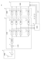
- FIG. 2 is a diagram showing the configuration of a ship information exchange device according to an embodiment of the present invention.
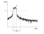
- FIG. 3 is a diagram showing an example of a frequency spectrum generated by the detection unit in the ship information exchange device according to the embodiment of the present invention.
- FIG. 4 is a diagram showing another example of the frequency spectrum generated by the detection unit in the ship information exchange device according to the embodiment of the present invention.
- FIG. 5 is a diagram showing another example of the frequency spectrum generated by the detection unit in the ship information exchange device according to the embodiment of the present invention.
- FIG. 1 is a diagram showing the configuration of a ship information exchange system according to an embodiment of the present invention.
- FIG. 2 is a diagram showing the configuration of a ship information exchange device according to an embodiment of the present invention.
- FIG. 3 is a diagram showing an example of a frequency spectrum generated by the detection unit in the ship information exchange device according to the embodiment of the present
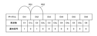
- FIG. 6 is a diagram illustrating an example of a comparison result notified to the processing unit by the detection unit in the ship information exchange device according to the embodiment of the present invention.
- FIG. 7 is a diagram showing another example of the comparison result notified to the processing unit by the detection unit in the ship information exchange device according to the embodiment of the present invention.
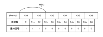
- FIG. 8 is a diagram showing another example of the comparison result notified to the processing unit by the detection unit in the ship information exchange device according to the embodiment of the present invention.
- FIG. 9 is a diagram showing another example of the comparison result notified to the processing unit by the detection unit in the ship information exchange device according to the embodiment of the present invention.
- FIG. 7 is a diagram showing another example of the comparison result notified to the processing unit by the detection unit in the ship information exchange device according to the embodiment of the present invention.
- FIG. 8 is a diagram showing another example of the comparison result notified to the processing unit by the detection unit in the ship information exchange device according to the embodiment of the present invention.
- FIG. 9 is a
- FIG. 10 is a diagram showing another example of the comparison result notified to the processing unit by the detection unit in the ship information exchange device according to the embodiment of the present invention.
- FIG. 11 is a flowchart illustrating an example of an operation when the ship information exchange device according to the embodiment of the present disclosure demodulates received data.
- FIG. 1 is a diagram showing the configuration of a ship information exchange system according to an embodiment of the present invention.
- a ship information exchange system 201 includes a plurality of ship information exchange devices 101.
- ship information exchange devices 101A, 101B, 101C, and 101D which are the ship information exchange device 101, are representatively shown.
- the ship information exchange system 201 may be configured to include two, three, or five or more ship information exchange devices 101.
- the ship information exchange device 101 is provided in the ship 1 or the land station.
- the ship information exchange device 101A is provided on the ship 1A
- the ship information exchange device 101B is provided on the ship 1B
- the ship information exchange device 101C is provided on the ship 1C
- the ship information exchange device 101D is provided on the ship 1C. It is located at the land station.
- the ship information exchange device 101 is, for example, an AIS (Automatic Identification System).
- the ship information exchange device 101 provided in the ship 1 periodically or irregularly transmits a radio signal containing the ship information of the ship 1 to other ship information exchange devices 101.
- the ship information includes at least one of a ship's identification code, a ship's name, a ship's position, a ship's course, a ship's speed, and a ship's destination.
- the ship information exchange devices 101A, 101B, and 101C generate modulated data by modulating communication data including ship information according to, for example, BPSK (Binary Phase Shift Keying), and transmit wireless signals including the generated modulated data.
- BPSK Binary Phase Shift Keying
- the ship information exchange devices 101A, 101B, and 101C may be configured to use other modulation methods such as QPSK (Quadrature PSK), 8PSK, and 16QAM (Quadrature Amplitude Modulation) instead of BPSK.
- QPSK Quadrature PSK
- 8PSK 8PSK
- 16QAM Quadrature Amplitude Modulation
- the ship information exchange device 101 receives a radio signal from another ship information exchange device 101 provided on the ship 1, and acquires modulated data from the received radio signal.
- the ship information exchange device 101 generates communication data by demodulating the acquired modulated data, and acquires ship information from the generated communication data.
- the ship information exchange device 101 notifies the user of information such as the identification code of the ship 1 indicated by the acquired ship information.
- the ship information exchange device 101 transmits and receives wireless signals using a plurality of channels that are predetermined frequency bands. As an example, the ship information exchange device 101 transmits and receives radio signals using channels CH1 to CH6, which are six channels.
- the ship information exchange devices 101A, 101B, and 101C transmit wireless signals using channels CH1, CH2, and CH3 of the six channels, respectively.
- the ship information exchange devices 101B, 101C, and 101D receive the radio signal of channel CH1 transmitted by the ship information exchange device 101A. Further, the ship information exchange devices 101A, 101C, and 101D receive the radio signal of channel CH2 transmitted by the ship information exchange device 101B. Further, the ship information exchange devices 101A, 101B, and 101D receive the radio signal of channel CH3 transmitted by the ship information exchange device 101C.
- ⁇ Assignment> For example, if the distance between the ship information exchange device 101 and another ship information exchange device 101 installed on a ship 1 other than the ships 1A, 1B, and 1C becomes less than a predetermined value, the ship information exchange device 101 The wireless signal transmitted by the information exchange device 101 is further received. Further, the ship information exchange device 101 may switch the channel of the wireless signal to be transmitted.
- the ship information exchange system 201 random access wireless communication is performed by the ship information exchange device 101. That is, the transmission order of the wireless signals of the ship information exchange device 101 provided in each ship 1 is not determined in advance, and each ship information exchange device 101 transmits the wireless signal at individual transmission timings.
- demodulation processing of six pieces of received data included in each of the six channels of wireless signals is performed in a time-sharing manner. It had to be done sequentially and iteratively.
- the ship information exchange device 101 may transmit a radio signal using a composite channel in which a plurality of channels in continuous frequency bands are combined, depending on the content of the ship information to be transmitted.
- the conventional ship information exchange device 101 in addition to demodulating the six pieces of received data included in each of the six channels of radio signals, the conventional ship information exchange device 101 demodulates the corresponding radio signals for each combination of multiple channels in continuous frequency bands. It was necessary to further demodulate the included received data.
- the processing load of demodulation processing increases, and data loss may occur due to the demodulation processing not being completed in time.
- the ship information exchange device 101 solves the above problems with the following configuration.
- FIG. 2 is a diagram showing the configuration of a ship information exchange device according to an embodiment of the present invention.
- ship information exchange device 101 includes a receiving section 10, a generating section 20, a detecting section 30, a storage section 40, and a processing section 50.
- the processing unit 50 is an example of a demodulation unit.
- the detection section 30 is connected to the processing section 50 via eleven signal lines SL1 to SL11.
- each of the signal lines SL1 to SL11 will also be referred to as signal line SL.
- Part or all of the generation unit 20 is realized by, for example, an FPGA (Field-Programmable Gate Array).
- a part or all of the detection unit 30 and the processing unit 50 are realized by, for example, a processor such as a CPU (Central Processing Unit) and a DSP (Digital Signal Processor).
- the storage unit 40 is, for example, a RAM (Random Access Memory), and includes memory areas 41_1 to 41_11.
- the receiving unit 10 includes an antenna 11 and an amplifier 12.
- the generation unit 20 includes a mixer 21, an AD (Analog to Digital) conversion unit 22, filter units 23_1 to 23_11, and transfer units 24_1 to 24_11.
- AD Analog to Digital
- filter units 23_1 to 23_11 will also be referred to as the filter unit 23
- transfer units 24_1 to 24_11 will also be referred to as the transfer unit 24.
- the transfer unit 24 is realized by, for example, DMA (Direct Memory Access).
- the receiving unit 10 receives wireless signals. More specifically, the amplifier 12 amplifies the radio signals of channels CH1 to CH6 received via the antenna 11 and outputs the amplified signals to the generation unit 20. (Generation part)
- the generation unit 20 generates received data of channels CH1 to CH6 used for transmitting ship information from the radio signal.
- the mixer 21 converts the wireless signal received from the amplifier 12 into a baseband analog signal using an LO (Local Oscillator) signal received from a local oscillator (not shown), and converts the converted analog signal into a baseband analog signal. It is output to the AD conversion section 22.
- LO Local Oscillator
- the AD conversion section 22 converts the analog signal received from the mixer 21 into a digital signal and outputs the digital signal to the filter section 23.
- the filter section 23 is, for example, a BPF (Band Pass Filter), and attenuates components outside a predetermined frequency band among the frequency components of the signal indicated by the digital signal received from the AD conversion section 22.
- BPF Band Pass Filter
- the filter units 23_1, 23_3, 23_5, 23_7, 23_9, and 23_11 attenuate components outside the frequency band corresponding to channels CH1 to CH6 among the frequency components of the signal indicated by the digital signal received from the AD conversion unit 22.
- the filter section 23_1 attenuates components outside the frequency band F1 corresponding to the channel CH1 among the frequency components of the signal indicated by the digital signal received from the AD conversion section 22.
- the filter section 23_3 attenuates components outside the frequency band F2 corresponding to the channel CH2 among the frequency components of the signal indicated by the digital signal received from the AD conversion section 22.
- the filter section 23_5 attenuates components outside the frequency band F3 corresponding to the channel CH3 among the frequency components of the signal indicated by the digital signal received from the AD conversion section 22.
- the filter section 23_7 attenuates components outside the frequency band F4 corresponding to the channel CH4 among the frequency components of the signal indicated by the digital signal received from the AD conversion section 22.
- the filter section 23_9 attenuates components outside the frequency band F5 corresponding to the channel CH5 among the frequency components of the signal indicated by the digital signal received from the AD conversion section 22. Furthermore, the filter section 23_11 attenuates components outside the frequency band F6 corresponding to the channel CH6 among the frequency components of the signal indicated by the digital signal received from the AD conversion section 22.
- the filter units 23_2, 23_4, 23_6, 23_8, and 23_10 each have a frequency band that includes the boundary frequencies of corresponding adjacent channels among the frequency components of the signal indicated by the digital signal received from the AD conversion unit 22. Attenuates external components.
- the filter section 23_2 selects a frequency band F1s between the center frequency C1 of the frequency band F1 and the center frequency C2 of the frequency band F2 among the frequency components of the signal indicated by the digital signal received from the AD conversion section 22. Attenuates external components. Furthermore, the filter section 23_4 attenuates components outside the frequency band F2s between the center frequency C2 and the center frequency C3 of the frequency band F3, among the frequency components of the signal indicated by the digital signal received from the AD conversion section 22. Furthermore, the filter section 23_6 attenuates components outside the frequency band F3s between the center frequency C3 and the center frequency C4 of the frequency band F4, among the frequency components of the signal indicated by the digital signal received from the AD conversion section 22.
- the filter section 23_8 attenuates components outside the frequency band F4s between the center frequency C4 and the center frequency C5 of the frequency band F5, among the frequency components of the signal indicated by the digital signal received from the AD conversion section 22.
- the filter section 23_10 attenuates components outside the frequency band F5s between the center frequency C5 and the center frequency C6 of the frequency band F6, among the frequency components of the signal indicated by the digital signal received from the AD conversion section 22.
- the transfer unit 24 stores the digital signal that has passed through the filter unit 23 in a memory area 41 in the storage unit 40.
- the transfer unit 24_1 stores the received data D1 of the channel CH1, which is a digital signal that has passed through the filter unit 23_1, in the memory area 41_1.
- the transfer unit 24_3 stores the received data D2 of the channel CH2, which is a digital signal that has passed through the filter unit 23_3, in the memory area 41_3.
- the transfer unit 24_5 stores the received data D3 of the channel CH3, which is a digital signal that has passed through the filter unit 23_5, in the memory area 41_5.
- the transfer unit 24_7 stores the received data D4 of the channel CH4, which is a digital signal that has passed through the filter unit 23_7, in the memory area 41_7.
- the transfer unit 24_9 stores the received data D5 of the channel CH5, which is a digital signal that has passed through the filter unit 23_9, in the memory area 41_9. Further, the transfer unit 24_11 stores the received data D6 of the channel CH6, which is a digital signal that has passed through the filter unit 23_11, in the memory area 41_11.
- the transfer unit 24_2 stores the received data D1s in the frequency band F1s, which is a digital signal that has passed through the filter unit 23_2, in the memory area 41_2.
- the transfer unit 24_4 stores the received data D2s in the frequency band F2s, which is a digital signal that has passed through the filter unit 23_4, in the memory area 41_4.
- the transfer unit 24_6 stores the received data D3s in the frequency band F3s, which is a digital signal that has passed through the filter unit 23_6, in the memory area 41_6.
- the transfer unit 24_8 stores the received data D4s in the frequency band F4s, which is a digital signal that has passed through the filter unit 23_8, in the memory area 41_8.
- the transfer unit 24_10 stores the received data D5s in the frequency band F5s, which is a digital signal that has passed through the filter unit 23_10, in the memory area 41_10.
- the detection unit 30 performs detection processing to detect the reception levels of channels CH1 to CH6. For example, in the detection process, the detection unit 30 further detects the reception level at the boundary frequency between adjacent channels.
- the detection unit 30 generates a frequency spectrum of the digital signal by performing FFT (Fast Fourier Transform) processing on the digital signal that has passed through the filter unit 23 for a predetermined length of time at a detection timing according to a predetermined detection cycle. .
- the detection unit 30 compares the signal strength of a predetermined frequency indicated by the generated frequency spectrum with a predetermined threshold TH1.
- the detection unit 30 generates the frequency spectrum SP1 of the digital signal by performing FFT processing on the digital signal that has passed through the filter unit 23_1.
- the detection unit 30 compares the signal strength at the center frequency C1 indicated by the frequency spectrum SP1 with a threshold value TH1.
- the detection unit 30 generates a frequency spectrum SP1s of the digital signal by performing FFT processing on the digital signal that has passed through the filter unit 23_2.
- the detection unit 30 compares the signal strength at the boundary frequency C1s, which is the boundary frequency between the channel CH1 and the channel CH2, indicated by the frequency spectrum SP1s, with the threshold value TH1.
- the detection unit 30 generates a frequency spectrum SP2 of the digital signal by performing FFT processing on the digital signal that has passed through the filter unit 23_3.
- the detection unit 30 compares the signal strength at the center frequency C2 indicated by the frequency spectrum SP2 and the threshold value TH1.
- the detection unit 30 generates a frequency spectrum SP2s of the digital signal by performing FFT processing on the digital signal that has passed through the filter unit 23_4.
- the detection unit 30 compares the signal strength at the boundary frequency C2s, which is the boundary frequency between the channel CH2 and the channel CH3, indicated by the frequency spectrum SP2s, with the threshold value TH1.
- the detection unit 30 generates a frequency spectrum SP3 of the digital signal by performing FFT processing on the digital signal that has passed through the filter unit 23_5.
- the detection unit 30 compares the signal strength at the center frequency C3 indicated by the frequency spectrum SP3 and the threshold value TH1.
- the detection unit 30 generates a frequency spectrum SP3s of the digital signal by performing FFT processing on the digital signal that has passed through the filter unit 23_6.
- the detection unit 30 compares the signal strength at a boundary frequency C3s, which is the boundary frequency between channel CH3 and channel CH4, indicated by the frequency spectrum SP3s, with a threshold value TH1.
- the detection unit 30 generates a frequency spectrum SP4 of the digital signal by performing FFT processing on the digital signal that has passed through the filter unit 23_7.
- the detection unit 30 compares the signal strength at the center frequency C4 indicated by the frequency spectrum SP4 with the threshold value TH1.
- the detection unit 30 generates a frequency spectrum SP4s of the digital signal by performing FFT processing on the digital signal that has passed through the filter unit 23_8.
- the detection unit 30 compares the signal strength at a boundary frequency C4s, which is the boundary frequency between channel CH4 and channel CH5, indicated by the frequency spectrum SP4s, with a threshold value TH1.
- the detection unit 30 generates a frequency spectrum SP5 of the digital signal by performing FFT processing on the digital signal that has passed through the filter unit 23_9.
- the detection unit 30 compares the signal strength at the center frequency C5 indicated by the frequency spectrum SP5 and the threshold value TH1.
- the detection unit 30 generates a frequency spectrum SP5s of the digital signal by performing FFT processing on the digital signal that has passed through the filter unit 23_10.
- the detection unit 30 compares the signal strength at a boundary frequency C5s, which is the boundary frequency between channel CH5 and channel CH6, indicated by the frequency spectrum SP5s, with a threshold value TH1.
- the detection unit 30 generates a frequency spectrum SP6 of the digital signal by performing FFT processing on the digital signal that has passed through the filter unit 23_11.
- the detection unit 30 compares the signal strength at the center frequency C6 indicated by the frequency spectrum SP6 and the threshold value TH1.
- each of the center frequencies C1 to C6 is also referred to as a center frequency C
- each of the boundary frequencies C1s to C5s is also referred to as a boundary frequency Cs.
- FIG. 3 is a diagram showing an example of a frequency spectrum generated by the detection unit in the ship information exchange device according to the embodiment of the present invention.
- FIG. 3 shows a frequency spectrum SP1 of a signal passed through the filter unit 23_1 generated by the detection unit 30 in the ship information exchange device 101 that has received the radio signal of the channel CH1 including ship information.
- the signal strength at the center frequency C1 is equal to or higher than the threshold value TH1.
- the signal strength at the boundary frequency C1s is less than the threshold TH1.
- FIG. 4 is a diagram showing another example of the frequency spectrum generated by the detection unit in the ship information exchange device according to the embodiment of the present invention.
- FIG. 4 shows a frequency spectrum SP2 of a signal passed through the filter unit 23_3 generated by the detection unit 30 in the ship information exchange device 101 that further receives the radio signal of the channel CH2 containing ship information in parallel. further shows.
- the signal strength at the center frequency C2 is at the threshold value. TH1 or more.
- the signal strength at the boundary frequency C1s is less than the threshold value TH1.
- FIG. 5 is a diagram showing another example of the frequency spectrum generated by the detection unit in the ship information exchange device according to the embodiment of the present invention.
- FIG. 5 shows a frequency spectrum SP1s of a signal passed through the filter unit 23_2 generated by the detection unit 30 in the ship information exchange device 101 that has received the radio signal of the combined channel CH12 of channels CH1 and CH2 containing ship information. .
- the signal strength at the boundary frequency C1s is equal to or higher than the threshold value TH1. be.
- the detection unit 30 notifies the processing unit 50 of the comparison result between the signal strength of the center frequency C and the boundary frequency Cs and the threshold TH1.
- the detection unit 30 sets the level of the notification signal, which is a signal output to the signal line SL, according to the comparison result between the signal strength of the center frequency C and the boundary frequency Cs and the threshold value TH1. The result is notified to the processing unit 50 via the signal line SL.
- the detection unit 30 sets the notification signal output to the corresponding signal line SL to a high level, and the signal strength of the center frequency C reaches the threshold TH1. If it is less than that, the notification signal output to the corresponding signal line SL is set to low level.
- the detection unit 30 sets the notification signal output to the corresponding signal line SL to a high level, and when the signal strength of the boundary frequency Cs is less than the threshold TH1. In this case, the notification signal output to the corresponding signal line SL is set to low level.
- FIG. 6 is a diagram showing an example of a comparison result notified to the processing unit by the detection unit in the ship information exchange device according to the embodiment of the present invention.
- FIG. 6 shows a notification signal outputted to the signal line SL by the detection unit 30 in the ship information exchange device 101 that has received the radio signal RS1 of the channel CH1 including ship information.
- a high level notification signal is shown as "1”
- a low level notification signal is shown as "0".
- FIG. 7 and subsequent figures The same applies to FIG. 7 and subsequent figures.
- the signal strength at the center frequency C1 is equal to or higher than the threshold value TH1, while the frequency spectrum SP2 ⁇ SP6 and the frequency spectrum SP1s ⁇ SP5s, the signal strength at the center frequencies C2 ⁇ C6 and the boundary frequencies C1s ⁇ C5s is less than the threshold TH1.
- the detection unit 30 sets the notification signal output to the signal line SL1 to a high level, and sets the notification signal output to the signal lines SL2 to SL11 to a low level.
- FIG. 7 is a diagram showing another example of the comparison result notified to the processing unit by the detection unit in the ship information exchange device according to the embodiment of the present invention.
- FIG. 7 shows a notification signal outputted to the signal line SL by the detection unit 30 in the ship information exchange device 101 that has received the radio signal RS1 of channel CH1 including ship information and the radio signal RS2 of channel CH2 including ship information. ing.
- the signal strength at the center frequencies C1 and C2 is equal to or higher than the threshold value TH1.
- the signal intensities at the center frequencies C3 to C6 and the boundary frequencies C1s to C5s are less than the threshold TH1.
- the detection unit 30 sets the notification signals output to the signal lines SL1 and SL2 to a high level, and sets the notification signals output to the signal lines SL2 and SL4 to SL11 to a low level.
- FIG. 8 is a diagram showing another example of the comparison result notified to the processing unit by the detection unit in the ship information exchange device according to the embodiment of the present invention.
- FIG. 8 shows a notification signal outputted to the signal line SL by the detection unit 30 in the ship information exchange device 101 that has received the radio signal RS12 of the combined channel CH12 of channels CH1 and CH2 including ship information.
- the signal strength at the center frequencies C1, C2 and the boundary frequency C1s is the threshold value.
- the signal intensities at center frequencies C3 to C6 and boundary frequencies C2s to C5s are less than threshold TH1.
- the detection unit 30 sets the notification signals output to the signal lines SL1 to SL3 to a high level, and sets the notification signals output to the signal lines SL4 to SL11 to a low level.
- FIG. 9 is a diagram showing another example of the comparison result notified to the processing unit by the detection unit in the ship information exchange device according to the embodiment of the present invention.
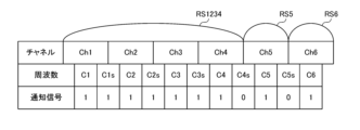
- FIG. 9 shows a ship information exchange device that receives a radio signal RS1234 of a composite channel CH1234 of channels CH1 to CH4 including ship information, a radio signal RS5 of a channel CH5 including ship information, and a radio signal RS5 of channel CH6 including ship information.
- 101 shows notification signals outputted by the detection unit 30 to the signal lines SL1 to SL11.
- the frequency spectra SP1 to SP6 and SP1s to SP3s generated by the detection unit 30 have center frequencies C1 to C6 and boundary frequencies.
- the signal strength at C1s to C3s is equal to or greater than the threshold TH1, while in the frequency spectra SP4s and SP5s, the signal strength at the boundary frequencies C4s and C5s is less than the threshold TH1.
- the detection unit 30 sets the notification signals output to the signal lines SL1 to SL7, SL9, and SL11 to a high level, and sets the notification signals output to the signal lines SL8 and SL10 to a low level.
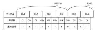
- FIG. 10 is a diagram showing another example of the comparison result notified to the processing unit by the detection unit in the ship information exchange device according to the embodiment of the present invention.
- FIG. 10 shows a detection unit in the ship information exchange device 101 that receives a radio signal RS1234 of a composite channel CH1234 of channels CH1 to CH4 including ship information and a radio signal RS56 of a composite channel CH56 of channels CH5 and CH6 including ship information.
- 30 shows notification signals output to signal lines SL1 to SL11.
- the frequency spectra SP1 to SP6, SP1s to SP3s, and SP5s generated by the detection unit 30 have center frequencies C1 to C6 and boundary frequencies.
- the signal strength at C1s to C3s and C5s is greater than or equal to the threshold TH1, while in the frequency spectrum SP4s, the signal strength at the boundary frequency C4s is less than the threshold TH1.
- the detection unit 30 sets the notification signals output to the signal lines SL1 to SL7 and SL9 to SL11 to high level, and sets the notification signal output to the signal line SL8 to low level.
- the detection unit 30 compares the signal strength at the center frequency C with a threshold TH1, and also compares the signal strength at the boundary frequency Cs with a threshold TH2 different from the threshold TH1, and sends the comparison results to the processing unit 50. It may be configured to notify.
- the detection unit 30 may be configured to use a value other than the threshold TH1 as the threshold used for comparison with the signal strength at at least one center frequency C, or may be configured to use a value other than the threshold TH1 for comparison with the signal strength at at least one center frequency Cs.
- the configuration may be such that a value other than the threshold TH1 is used as the threshold used for comparison with the signal strength.
- the processing unit 50 determines received data to be demodulated according to the detection result of the reception level by the detection unit 30, and demodulates the determined received data to be demodulated. More specifically, the processing unit 50 determines the received data to be demodulated according to the comparison result notified from the detection unit 30, that is, the level of the notification signal received from the detection unit 30 via the signal line SL. Received data to be demodulated is acquired from the storage unit 40 and demodulated.
- the processing unit 50 determines the number of channels used to transmit the ship information based on the detection result of the reception level by the detection unit 30, and determines the received data to be demodulated based on the determination result.
- the processing unit 50 demodulates the reception data D1 of the channel CH1.
- the processing unit 50 determines that the channel used for transmitting the ship information is the channel CH1. In this case, each time the transfer unit 24_1 stores the received data D1 in the memory area 41_1, the processing unit 50 extracts the received data D1 from the memory area 41_1 and demodulates the received data D1. On the other hand, while receiving the notification signal shown in FIG. 6 from the detection unit 30, the processing unit 50 erases the received data stored in the memory areas 41_2 to 41_11 by the transfer units 24_2 to 24_11 without demodulating it.
- the processing unit 50 determines that the reception level at the center frequency C1 of the channel CH1, which is a channel in a continuous frequency band, and the reception level at the center frequency C2 of the channel CH2 are equal to or higher than a predetermined value, and the reception level at the boundary frequency C1s is is less than a predetermined value, the received data D1 of channel CH1 and the received data D2 of channel CH2 are respectively demodulated.
- the processing unit 50 determines that the channels used for transmitting ship information are channels CH1 and CH2. In this case, each time the transfer unit 24_1 stores the received data D1 in the memory area 41_1, the processing unit 50 extracts the received data D1 from the memory area 41_1, demodulates it, and stores the received data D1 in the memory area 41_3 by the transfer unit 24_3. Every time D2 is saved, the received data D2 is taken out from the memory area 41_3 and demodulated. On the other hand, in a state in which the processing unit 50 receives the notification signal shown in FIG. to erase.
- the processing unit 50 determines that the reception level at the center frequency of each of the channels in the plurality of continuous frequency bands is equal to or higher than a predetermined value, and that the processing unit 50 When the reception level at the frequency is equal to or higher than a predetermined value, composite data obtained by combining each reception data of channels of a plurality of consecutive frequency bands is demodulated.
- the processing unit 50 determines that the reception level at the center frequency C1 of channel CH1, which is a channel in a continuous frequency band, and the reception level at the center frequency C2 of channel CH2 are equal to or higher than a predetermined value, and the reception level at the boundary frequency C1s is If the value is greater than or equal to the predetermined value, combined data obtained by combining received data D1 and D2 of channel CH1 and channel CH2 is demodulated.
- the processing unit 50 determines that the channel used for transmitting ship information is the composite channel CH12 of channels CH1 and CH2. judge. In this case, the processing unit 50 extracts and combines the received data D1, D2 from the memory areas 41_1, 41_3 every time the transfer units 24_1, 24_3 save the received data D1, D2 in the memory areas 41_1, 41_3.
- the synthesized data D12 is generated by the following steps, and the generated synthesized data D12 is demodulated.
- the processing unit 50 erases the received data stored in the memory areas 41_4 to 41_11 by the transfer units 24_4 to 24_11 without demodulating it.
- the processing unit 50 may be configured to generate the composite data D12 by extracting and combining the received data D1, D1s, and D2 from the memory areas 41_1 to 41_3.
- Each device in the ship information exchange system includes a computer including a memory, and an arithmetic processing unit such as a CPU in the computer executes a program including some or all of the steps in the flowchart below. Read from the memory and execute. The programs for these multiple devices can be installed from outside. The programs of these plurality of devices are stored in recording media or distributed via communication lines.
- FIG. 11 is a flowchart illustrating an example of an operation when the ship information exchange device according to the embodiment of the present disclosure demodulates received data.
- the ship information exchange device 101 starts receiving wireless signals (step S11).
- the ship information exchange device 101 starts generating and storing the received data D1 to D6 of the channels CH1 to CH6 and the received data D1s to D5s of the frequency bands F1s to F5s in the storage unit 40 (step S12).
- the ship information exchange device 101 waits for a detection timing according to a predetermined detection cycle (NO in step S13), and when the detection timing arrives (YES in step S13), performs FFT processing on the digital signal that has passed through the filter section 23. As a result, frequency spectra SP1 to SP6 and SP1s to SP5s are generated (step S14).
- the ship information exchange device 101 uses the generated frequency spectra SP1 to SP6, SP1s to SP5s to detect the reception levels of the channels CH1 to CH6 and the reception levels at the boundary frequencies C1s to C5s. More specifically, the ship information exchange device 101 compares the signal strength at the center frequency C and the signal strength at the boundary frequency Cs with the threshold value TH1 (step S15).
- the ship information exchange device 101 determines the number of channels used for transmitting ship information based on the comparison result, and determines the received data to be demodulated based on the determination result (step S16).
- the ship information exchange device 101 starts demodulating the received data determined to be demodulated. More specifically, each time the ship information exchange device 101 generates received data D1 to D6, D1s to D5s, the received data to be demodulated from among the generated received data D1 to D6, D1s to D5s is stored in the storage unit 40. The received data that is not to be demodulated is deleted from the storage unit 40 (step S17).
- the ship information exchange device 101 waits for a new detection timing (NO in step S13).
- the detection unit 30 detects the center frequencies C1 to C6 and the boundary frequencies indicated by the frequency spectra SP1 to SP6, SP1s to SP5s of the digital signal that has passed through the filter unit 23.
- the detection unit 30 may be configured to perform detection processing in an analog stage.
- a plurality of sets of analog BPFs and AD conversion sections are provided after the mixer 21, and the detection section 30 detects the signal strength of the center frequency C and boundary frequency Cs of the analog signal that has passed through each analog BPF, and the threshold value.
- the configuration may be such that the comparison result is compared with TH1 and the comparison result is notified to the processing unit 50.
- the generation unit 20 is configured to include the transfer units 24_2, 24_4, 24_6, 24_8, and 24_10, but the present invention is not limited to this.
- the generation unit 20 may include the transfer units 24_1, 24_3, 24_5, 24_7, 24_9, and 24_11, but may not include the transfer units 24_2, 24_4, 24_6, 24_8, and 24_10. In this case, the generation unit 20 generates composite data without using the received data D1s to D5s.
- the receiving unit 10 receives radio signals.
- the generation unit 20 generates received data of channels CH1 to CH6 used for transmitting ship information from the radio signal.
- the detection unit 30 detects the reception levels of channels CH1 to CH6.
- the processing unit 50 demodulates the received data.
- the processing unit 50 determines received data to be demodulated according to the detection result of the reception level.
- the radio signals of channels CH1 to CH6 each contain ship information.
- the demodulation processing of six pieces of received data is performed sequentially and repeatedly in a time-sharing manner, it is possible to selectively demodulate the received data that includes ship information, so that the received data that does not include ship information can be demodulated. It is possible to suppress an increase in the processing load caused by demodulating the data, and to further speed up the response of various processes in the processing unit 50. Therefore, the processing load of demodulation processing can be reduced, and the processing cost and cost cost for performing demodulation can be reduced.
- the processing unit 50 determines the number of channels used for transmitting the ship information based on the detection result, and determines the received data to be demodulated based on the determination result.
- received data on the composite channel can be appropriately demodulated.
- the detection unit 30 further detects the reception level at the boundary frequency between adjacent channels.
- the received data of channel CH1 can be demodulated separately from the received data of combined channel CH12 of channels CH1 and CH2.
- reception level of channel CH1 and channel CH2 in continuous frequency bands is equal to or higher than a predetermined value, and the reception level at the boundary frequency between channel CH1 and channel CH2 is less than a predetermined value,
- the received data of CH1 and the received data of channel CH2 are each demodulated.
- the received data of channel CH1 and the received data of channel CH2 can be demodulated separately from the received data of combined channel CH12 of channels CH1 and CH2.
- reception level of channel CH1 and channel CH2 in continuous frequency bands is equal to or higher than a predetermined value
- reception level at the boundary frequency between channel CH1 and channel CH2 is equal to or higher than a predetermined value
- the received data of the combined channel CH12 of channels CH1 and CH2 can be demodulated separately from the received data of channel CH1 and the received data of channel CH2.
- the processing unit 50 Combined data obtained by combining each received data of channels of a plurality of frequency bands is demodulated.
- the processing unit 50 determines the received data to be demodulated based on the comparison result between the reception level of the channel and the threshold TH1, and the comparison result between the reception level at the boundary frequency and a threshold TH2 different from the threshold TH1. do.
- the number of channels used for transmitting ship information can be determined more accurately than a configuration in which the reception level is detected using a common threshold.
- the ship information includes at least one of a ship's identification code, a ship's name, a ship's position, a ship's course, a ship's speed, and a ship's destination.
- the ship information exchange method is a ship information exchange method in the ship information exchange device 101.
- this ship information exchange method first, a radio signal is received. Next, received data for channels CH1 to CH6 used for transmitting ship information is generated from the radio signal. Next, the reception levels of channels CH1 to CH6 are detected. Next, the received data to be demodulated is determined according to the reception level detection result. Next, the received data to be demodulated is demodulated.
- the radio signals of channels CH1 to CH6 can be Compared to a configuration in which the demodulation processing of the six pieces of received data is performed sequentially and repeatedly in a time-sharing manner, it is possible to selectively demodulate the received data that includes ship information, so it is possible to demodulate the received data that does not include ship information. It is possible to suppress an increase in processing load due to data demodulation and to speed up the response of various processes. Therefore, the processing load of demodulation processing can be reduced, and the processing cost and cost cost for performing demodulation can be reduced.
Landscapes
- Engineering & Computer Science (AREA)
- Computer Networks & Wireless Communication (AREA)
- Signal Processing (AREA)
- Mobile Radio Communication Systems (AREA)
- Circuits Of Receivers In General (AREA)
Abstract
【課題】復調処理の処理負荷を低減する。 【解決手段】船舶情報交換装置は、無線信号を受信する受信部と、前記無線信号から、船舶情報の伝送に用いられる複数のチャネルの受信データを生成する生成部と、各前記チャネルの受信レベルを検知する検知部と、前記受信データを復調する復調部とを備え、前記復調部は、前記受信レベルの検知結果に応じて復調対象の前記受信データを決定する。
Description
本開示は、船舶情報交換装置、船舶情報交換方法および船舶情報交換プログラムに関する。
従来、船舶間において、船舶の識別符号等の船舶情報を送受信する技術が知られている。船舶情報は、予め定められた周波数帯域のチャネルを用いて送受信され、受信側の装置において復調される。
しかしながら、従来の技術では、船舶情報を受信した装置における復調処理の処理負荷が大きくなり、復調処理が間に合わないことによるデータロスが生じる場合がある。
この発明は、上述の課題を解決するためになされたもので、その目的は、復調処理の処理負荷を低減することが可能な船舶情報交換装置、船舶情報交換方法および船舶情報交換プログラムを提供することである。
(1)上記課題を解決するために、この発明のある局面に係る船舶情報交換装置は、無線信号を受信する受信部と、前記無線信号から、船舶情報の伝送に用いられる複数のチャネルの受信データを生成する生成部と、各前記チャネルの受信レベルを検知する検知部と、前記受信データを復調する復調部とを備え、前記復調部は、前記受信レベルの検知結果に応じて復調対象の前記受信データを決定する。
このように、複数のチャネルの受信レベルに応じて復調対象の受信データを決定する構成により、無線信号に船舶情報が含まれているか否かに関わらずすべてのチャネルの無線信号にそれぞれ含まれる受信データの復調処理を時分割で逐次的に、かつ繰り返し行う構成と比べて、船舶情報が含まれる受信データを選択的に復調することができるので、船舶情報が含まれない受信データを復調することによる処理負荷の増大を抑制し、復調部における各種処理のレスポンスをより高速化することができる。したがって、復調処理の処理負荷を低減し、復調を行うための処理コストおよび原価コストを低減することができる。
(2)前記復調部は、前記検知結果に基づいて、前記船舶情報の伝送に用いられた前記チャネルの数を判定し、判定結果に基づいて復調対象の前記受信データを決定する場合がある。
(3)前記検知部は、隣接する前記チャネルの境界の周波数における受信レベルをさらに検知する場合がある。
(4)前記復調部は、第1の前記チャネルの前記受信レベルが所定値以上であり、かつ前記第1のチャネルと、前記第1のチャネルに隣接する前記チャネルとの境界の周波数における前記受信レベルが所定値未満である場合、前記第1のチャネルの前記受信データを復調する場合がある。
(5)前記復調部は、連続する周波数帯域の前記チャネルである第1の前記チャネルおよび第2の前記チャネルの前記受信レベルが所定値以上であり、かつ前記第1のチャネルと前記第2のチャネルとの境界の周波数における前記受信レベルが所定値未満である場合、前記第1のチャネルの前記受信データおよび前記第2のチャネルの前記受信データをそれぞれ復調する場合がある。
(6)前記復調部は、連続する周波数帯域の前記チャネルである第1の前記チャネルおよび第2の前記チャネルの前記受信レベルが所定値以上であり、かつ前記第1のチャネルと前記第2のチャネルとの境界の周波数における前記受信レベルが所定値以上である場合、前記第1のチャネルおよび前記第2のチャネルの各前記受信データが合成された合成データを復調する場合がある。
(7)前記復調部は、連続する複数の周波数帯域の前記チャネルの各々の前記受信レベルが所定値以上であり、かつ互いに隣接する前記チャネルの各境界の周波数における前記受信レベルが所定値以上である場合、前記連続する複数の周波数帯域の前記チャネルの各前記受信データが合成された合成データを復調する場合がある。
(8)前記復調部は、前記チャネルの前記受信レベルと、第1の閾値との比較結果、および前記境界の周波数における前記受信レベルと、前記第1の閾値とは異なる第2の閾値との比較結果に基づいて復調対象の前記受信データを決定する場合がある。
(9)前記船舶情報は、船舶の識別符号、船名、船舶の位置、船舶の針路、船速、および船舶の目的地のうちの少なくともいずれか1つを含む場合がある。
(10)上記課題を解決するために、この発明のある局面に係る船舶情報交換方法は、船舶情報交換装置における船舶情報交換方法であって、無線信号を受信し、前記無線信号から、船舶情報の伝送に用いられる複数のチャネルの受信データを生成し、各前記チャネルの受信レベルを検知し、前記受信レベルの検知結果に応じて復調対象の前記受信データを決定し、前記復調対象の前記受信データを復調する。
(11)上記課題を解決するために、この発明のある局面に係る船舶情報交換プログラムは、無線信号を受信する処理と、前記無線信号から、船舶情報の伝送に用いられる複数のチャネルの受信データを生成する処理と、各前記チャネルの受信レベルを検知する処理と、前記受信レベルの検知結果に応じて復調対象の前記受信データを決定する処理と、前記復調対象の前記受信データを復調する処理とを実行する。
本発明によれば、復調処理の処理負荷を低減することができる。
以下、本開示の実施の形態について図面を用いて説明する。なお、図中同一または相当部分には同一符号を付してその説明は繰り返さない。また、以下に記載する実施の形態の少なくとも一部を任意に組み合わせてもよい。
[構成および基本動作]
<船舶情報交換システム>
図1は、本発明の実施の形態に係る船舶情報交換システムの構成を示す図である。図1を参照して、船舶情報交換システム201は、複数の船舶情報交換装置101を備える。図1では、船舶情報交換装置101である船舶情報交換装置101A,101B,101C,101Dを代表的に示している。船舶情報交換システム201は、2つ、3つまたは5つ以上の船舶情報交換装置101を備える構成であってもよい。
<船舶情報交換システム>
図1は、本発明の実施の形態に係る船舶情報交換システムの構成を示す図である。図1を参照して、船舶情報交換システム201は、複数の船舶情報交換装置101を備える。図1では、船舶情報交換装置101である船舶情報交換装置101A,101B,101C,101Dを代表的に示している。船舶情報交換システム201は、2つ、3つまたは5つ以上の船舶情報交換装置101を備える構成であってもよい。
船舶情報交換装置101は、船舶1または陸上局に設けられる。たとえば、船舶情報交換装置101Aは船舶1Aに設けられており、船舶情報交換装置101Bは船舶1Bに設けられており、船舶情報交換装置101Cは船舶1Cに設けられており、船舶情報交換装置101Dは陸上局に設けられている。船舶情報交換装置101は、たとえばAIS(Automatic Identification System)である。
船舶1に設けられた船舶情報交換装置101は、定期的または不定期に、当該船舶1の船舶情報を含む無線信号を他の船舶情報交換装置101へ送信する。たとえば、船舶情報は、船舶の識別符号、船名、船舶の位置、船舶の針路、船速、および船舶の目的地のうちの少なくともいずれか1つを含む。
より詳細には、船舶情報交換装置101A,101B,101Cは、船舶情報を含む通信データをたとえばBPSK(Binary Phase Shift Keying)に従って変調することにより変調データを生成し、生成した変調データを含む無線信号を送信する。なお、船舶情報交換装置101A,101B,101Cは、BPSKの代わりに、QPSK(Quadrature PSK)、8PSKおよび16QAM(Quadrature Amplitude Modulation)等の他の変調方式を用いる構成であってもよい。
船舶情報交換装置101は、船舶1に設けられた他の船舶情報交換装置101から無線信号を受信し、受信した無線信号から変調データを取得する。船舶情報交換装置101は、取得した変調データを復調することにより通信データを生成し、生成した通信データから船舶情報を取得する。船舶情報交換装置101は、取得した船舶情報が示す船舶1の識別符号等の情報をユーザに通知する。
船舶情報交換装置101は、予め定められた周波数帯域である複数のチャネルを用いて無線信号の送受信を行う。一例として、船舶情報交換装置101は、6つのチャネルであるチャネルCH1~CH6を用いて無線信号の送受信を行う。
たとえば、船舶情報交換装置101A,101B,101Cは、6つのチャネルのうちのチャネルCH1,CH2,CH3を用いて無線信号をそれぞれ送信する。
この場合、船舶情報交換装置101B,101C,101Dは、船舶情報交換装置101Aにより送信されたチャネルCH1の無線信号を受信する。また、船舶情報交換装置101A,101C,101Dは、船舶情報交換装置101Bにより送信されたチャネルCH2の無線信号を受信する。また、船舶情報交換装置101A,101B,101Dは、船舶情報交換装置101Cにより送信されたチャネルCH3の無線信号を受信する。
<課題>
たとえば、船舶情報交換装置101は、船舶1A,1B,1C以外の他の船舶1に搭載された他の船舶情報交換装置101との間の距離が所定値未満となった場合、当該他の船舶情報交換装置101により送信された無線信号をさらに受信する。また、船舶情報交換装置101は、送信する無線信号のチャネルを切り替える場合がある。
たとえば、船舶情報交換装置101は、船舶1A,1B,1C以外の他の船舶1に搭載された他の船舶情報交換装置101との間の距離が所定値未満となった場合、当該他の船舶情報交換装置101により送信された無線信号をさらに受信する。また、船舶情報交換装置101は、送信する無線信号のチャネルを切り替える場合がある。
さらに、船舶情報交換システム201では、船舶情報交換装置101によるランダムアクセス方式の無線通信が行われる。すなわち、各船舶1に設けられた船舶情報交換装置101の無線信号の送信順は予め定められておらず、各船舶情報交換装置101は個別の送信タイミングにおいて無線信号を送信する。
したがって、従来の船舶情報交換装置101では、受信した無線信号に船舶情報が含まれているか否かに関わらず、6つのチャネルの無線信号にそれぞれ含まれる6つの受信データの復調処理を時分割で逐次的に、かつ繰り返し行う必要があった。
さらに、船舶情報交換装置101は、送信すべき船舶情報の内容等に応じて、連続する周波数帯域の複数のチャネルが合成された合成チャネルを用いて無線信号を送信する場合がある。
そのため、従来の船舶情報交換装置101では、6つのチャネルの無線信号にそれぞれ含まれる6つの受信データの復調処理に加えて、連続する周波数帯域の複数のチャネルの組み合わせごとに、対応する無線信号に含まれる受信データの復調処理をさらに行う必要があった。
したがって、従来の船舶情報交換装置101では、復調処理の処理負荷が大きくなり、復調処理が間に合わないことによるデータロスが生じる場合がある。
本発明の実施の形態に係る船舶情報交換装置101では、以下のような構成により、上記の課題を解決する。
<船舶情報交換装置>
図2は、本発明の実施の形態に係る船舶情報交換装置の構成を示す図である。図2を参照して、船舶情報交換装置101は、受信部10と、生成部20と、検知部30と、記憶部40と、処理部50とを備える。処理部50は、復調部の一例である。たとえば、検知部30は、11本の信号線SL1~SL11を介して処理部50と接続されている。以下、信号線SL1~SL11の各々を信号線SLとも称する。
図2は、本発明の実施の形態に係る船舶情報交換装置の構成を示す図である。図2を参照して、船舶情報交換装置101は、受信部10と、生成部20と、検知部30と、記憶部40と、処理部50とを備える。処理部50は、復調部の一例である。たとえば、検知部30は、11本の信号線SL1~SL11を介して処理部50と接続されている。以下、信号線SL1~SL11の各々を信号線SLとも称する。
生成部20の一部または全部は、たとえばFPGA(Field-Programmable Gate Array)により実現される。検知部30および処理部50の一部または全部は、たとえば、CPU(Central Processing Unit)およびDSP(Digital Signal Processor)等のプロセッサにより実現される。記憶部40は、たとえばRAM(Random Access Memory)であり、メモリ領域41_1~41_11を含む。
受信部10は、アンテナ11と、アンプ12とを含む。
生成部20は、ミキサ21と、AD(Analog to Digital)変換部22と、フィルタ部23_1~23_11と、転送部24_1~24_11とを含む。以下、フィルタ部23_1~23_11の各々をフィルタ部23とも称し、転送部24_1~24_11の各々を転送部24とも称する。転送部24は、たとえばDMA(Direct Memory Access)により実現される。
(受信部)
受信部10は、無線信号を受信する。より詳細には、アンプ12は、アンテナ11経由で受信したチャネルCH1~CH6の無線信号を増幅して生成部20へ出力する。
(生成部)
受信部10は、無線信号を受信する。より詳細には、アンプ12は、アンテナ11経由で受信したチャネルCH1~CH6の無線信号を増幅して生成部20へ出力する。
(生成部)
生成部20は、無線信号から、船舶情報の伝送に用いられるチャネルCH1~CH6の受信データを生成する。
より詳細には、ミキサ21は、アンプ12から受けた無線信号を、図示しない局部発振器から受けたLO(Local Oscillator)信号を用いてベースバンド帯のアナログ信号に変換し、変換後のアナログ信号をAD変換部22へ出力する。
AD変換部22は、ミキサ21から受けたアナログ信号をデジタル変換したデジタル信号をフィルタ部23へ出力する。
フィルタ部23は、たとえばBPF(Band Pass Filter)であり、AD変換部22から受けたデジタル信号が示す信号の周波数成分のうち、所定の周波数帯域外の成分を減衰させる。
たとえば、フィルタ部23_1,23_3,23_5,23_7,23_9,23_11は、AD変換部22から受けたデジタル信号が示す信号の周波数成分のうち、チャネルCH1~CH6に対応する周波数帯域外の成分をそれぞれ減衰させる。
より詳細には、フィルタ部23_1は、AD変換部22から受けたデジタル信号が示す信号の周波数成分のうち、チャネルCH1に対応する周波数帯域F1外の成分を減衰させる。また、フィルタ部23_3は、AD変換部22から受けたデジタル信号が示す信号の周波数成分のうち、チャネルCH2に対応する周波数帯域F2外の成分を減衰させる。また、フィルタ部23_5は、AD変換部22から受けたデジタル信号が示す信号の周波数成分のうち、チャネルCH3に対応する周波数帯域F3外の成分を減衰させる。また、フィルタ部23_7は、AD変換部22から受けたデジタル信号が示す信号の周波数成分のうち、チャネルCH4に対応する周波数帯域F4外の成分を減衰させる。また、フィルタ部23_9は、AD変換部22から受けたデジタル信号が示す信号の周波数成分のうち、チャネルCH5に対応する周波数帯域F5外の成分を減衰させる。また、フィルタ部23_11は、AD変換部22から受けたデジタル信号が示す信号の周波数成分のうち、チャネルCH6に対応する周波数帯域F6外の成分を減衰させる。
また、たとえば、フィルタ部23_2,23_4,23_6,23_8,23_10は、AD変換部22から受けたデジタル信号が示す信号の周波数成分のうち、それぞれ対応の隣接するチャネルの境界の周波数、を含む周波数帯域外の成分を減衰させる。
より詳細には、フィルタ部23_2は、AD変換部22から受けたデジタル信号が示す信号の周波数成分のうち、周波数帯域F1の中心周波数C1と周波数帯域F2の中心周波数C2との間の周波数帯域F1s外の成分を減衰させる。また、フィルタ部23_4は、AD変換部22から受けたデジタル信号が示す信号の周波数成分のうち、中心周波数C2と周波数帯域F3の中心周波数C3との間の周波数帯域F2s外の成分を減衰させる。また、フィルタ部23_6は、AD変換部22から受けたデジタル信号が示す信号の周波数成分のうち、中心周波数C3と周波数帯域F4の中心周波数C4との間の周波数帯域F3s外の成分を減衰させる。また、フィルタ部23_8は、AD変換部22から受けたデジタル信号が示す信号の周波数成分のうち、中心周波数C4と周波数帯域F5の中心周波数C5との間の周波数帯域F4s外の成分を減衰させる。また、フィルタ部23_10は、AD変換部22から受けたデジタル信号が示す信号の周波数成分のうち、中心周波数C5と周波数帯域F6の中心周波数C6との間の周波数帯域F5s外の成分を減衰させる。
転送部24は、フィルタ部23を通過したデジタル信号を記憶部40におけるメモリ領域41に保存する。
より詳細には、転送部24_1は、フィルタ部23_1を通過したデジタル信号であるチャネルCH1の受信データD1をメモリ領域41_1に保存する。また、転送部24_3は、フィルタ部23_3を通過したデジタル信号であるチャネルCH2の受信データD2をメモリ領域41_3に保存する。また、転送部24_5は、フィルタ部23_5を通過したデジタル信号であるチャネルCH3の受信データD3をメモリ領域41_5に保存する。また、転送部24_7は、フィルタ部23_7を通過したデジタル信号であるチャネルCH4の受信データD4をメモリ領域41_7に保存する。また、転送部24_9は、フィルタ部23_9を通過したデジタル信号であるチャネルCH5の受信データD5をメモリ領域41_9に保存する。また、転送部24_11は、フィルタ部23_11を通過したデジタル信号であるチャネルCH6の受信データD6をメモリ領域41_11に保存する。
また、転送部24_2は、フィルタ部23_2を通過したデジタル信号である周波数帯域F1sの受信データD1sをメモリ領域41_2に保存する。また、転送部24_4は、フィルタ部23_4を通過したデジタル信号である周波数帯域F2sの受信データD2sをメモリ領域41_4に保存する。また、転送部24_6は、フィルタ部23_6を通過したデジタル信号である周波数帯域F3sの受信データD3sをメモリ領域41_6に保存する。また、転送部24_8は、フィルタ部23_8を通過したデジタル信号である周波数帯域F4sの受信データD4sをメモリ領域41_8に保存する。また、転送部24_10は、フィルタ部23_10を通過したデジタル信号である周波数帯域F5sの受信データD5sをメモリ領域41_10に保存する。
(検知部)
検知部30は、チャネルCH1~CH6の受信レベルを検知する検知処理を行う。たとえば、検知部30は、検知処理において、隣接するチャネルの境界の周波数における受信レベルをさらに検知する。
検知部30は、チャネルCH1~CH6の受信レベルを検知する検知処理を行う。たとえば、検知部30は、検知処理において、隣接するチャネルの境界の周波数における受信レベルをさらに検知する。
たとえば、検知部30は、所定の検知周期に従う検知タイミングにおいて、所定長の時間においてフィルタ部23を通過したデジタル信号をFFT(Fast Fourier Transform)処理することにより、当該デジタル信号の周波数スペクトルを生成する。検知部30は、生成した周波数スペクトルが示す所定の周波数の信号強度と、所定の閾値TH1とを比較する。
より詳細には、検知部30は、フィルタ部23_1を通過したデジタル信号をFFT処理することにより、当該デジタル信号の周波数スペクトルSP1を生成する。検知部30は、周波数スペクトルSP1が示す中心周波数C1における信号強度と、閾値TH1とを比較する。
また、検知部30は、フィルタ部23_2を通過したデジタル信号をFFT処理することにより、当該デジタル信号の周波数スペクトルSP1sを生成する。検知部30は、周波数スペクトルSP1sが示す、チャネルCH1とチャネルCH2との境界の周波数である境界周波数C1sにおける信号強度と、閾値TH1とを比較する。
また、検知部30は、フィルタ部23_3を通過したデジタル信号をFFT処理することにより、当該デジタル信号の周波数スペクトルSP2を生成する。検知部30は、周波数スペクトルSP2が示す中心周波数C2における信号強度と、閾値TH1とを比較する。
また、検知部30は、フィルタ部23_4を通過したデジタル信号をFFT処理することにより、当該デジタル信号の周波数スペクトルSP2sを生成する。検知部30は、周波数スペクトルSP2sが示す、チャネルCH2とチャネルCH3との境界の周波数である境界周波数C2sにおける信号強度と、閾値TH1とを比較する。
また、検知部30は、フィルタ部23_5を通過したデジタル信号をFFT処理することにより、当該デジタル信号の周波数スペクトルSP3を生成する。検知部30は、周波数スペクトルSP3が示す中心周波数C3における信号強度と、閾値TH1とを比較する。
また、検知部30は、フィルタ部23_6を通過したデジタル信号をFFT処理することにより、当該デジタル信号の周波数スペクトルSP3sを生成する。検知部30は、周波数スペクトルSP3sが示す、チャネルCH3とチャネルCH4との境界の周波数である境界周波数C3sにおける信号強度と、閾値TH1とを比較する。
また、検知部30は、フィルタ部23_7を通過したデジタル信号をFFT処理することにより、当該デジタル信号の周波数スペクトルSP4を生成する。検知部30は、周波数スペクトルSP4が示す中心周波数C4における信号強度と、閾値TH1とを比較する。
また、検知部30は、フィルタ部23_8を通過したデジタル信号をFFT処理することにより、当該デジタル信号の周波数スペクトルSP4sを生成する。検知部30は、周波数スペクトルSP4sが示す、チャネルCH4とチャネルCH5との境界の周波数である境界周波数C4sにおける信号強度と、閾値TH1とを比較する。
また、検知部30は、フィルタ部23_9を通過したデジタル信号をFFT処理することにより、当該デジタル信号の周波数スペクトルSP5を生成する。検知部30は、周波数スペクトルSP5が示す中心周波数C5における信号強度と、閾値TH1とを比較する。
また、検知部30は、フィルタ部23_10を通過したデジタル信号をFFT処理することにより、当該デジタル信号の周波数スペクトルSP5sを生成する。検知部30は、周波数スペクトルSP5sが示す、チャネルCH5とチャネルCH6との境界の周波数である境界周波数C5sにおける信号強度と、閾値TH1とを比較する。
また、検知部30は、フィルタ部23_11を通過したデジタル信号をFFT処理することにより、当該デジタル信号の周波数スペクトルSP6を生成する。検知部30は、周波数スペクトルSP6が示す中心周波数C6における信号強度と、閾値TH1とを比較する。
以下、中心周波数C1~C6の各々を中心周波数Cとも称し、境界周波数C1s~C5sの各々を境界周波数Csとも称する。
図3は、本発明の実施の形態に係る船舶情報交換装置における検知部により生成される周波数スペクトルの一例を示す図である。図3は、船舶情報を含むチャネルCH1の無線信号を受信した船舶情報交換装置101において、検知部30により生成されるフィルタ部23_1の通過信号の周波数スペクトルSP1を示している。
図3を参照して、船舶情報を含むチャネルCH1の無線信号を受信した船舶情報交換装置101において、検知部30により生成される周波数スペクトルSP1では、中心周波数C1における信号強度は閾値TH1以上である。一方、周波数スペクトルSP1では、境界周波数C1sにおける信号強度は閾値TH1未満である。
図4は、本発明の実施の形態に係る船舶情報交換装置における検知部により生成される周波数スペクトルの他の例を示す図である。図4は、図3と比べて、船舶情報を含むチャネルCH2の無線信号を並行してさらに受信した船舶情報交換装置101において、検知部30により生成されるフィルタ部23_3の通過信号の周波数スペクトルSP2をさらに示している。
図4を参照して、船舶情報を含むチャネルCH2の無線信号を並行してさらに受信した船舶情報交換装置101において、検知部30により生成される周波数スペクトルSP2では、中心周波数C2における信号強度は閾値TH1以上である。一方、周波数スペクトルSP2では、境界周波数C1sにおける信号強度は閾値TH1未満である。
図5は、本発明の実施の形態に係る船舶情報交換装置における検知部により生成される周波数スペクトルの他の例を示す図である。図5は、船舶情報を含むチャネルCH1,CH2の合成チャネルCH12の無線信号を受信した船舶情報交換装置101において、検知部30により生成されるフィルタ部23_2の通過信号の周波数スペクトルSP1sを示している。
図5を参照して、船舶情報を含む合成チャネルCH12の無線信号を受信した船舶情報交換装置101において、検知部30により生成される周波数スペクトルSP1sでは、境界周波数C1sにおける信号強度は閾値TH1以上である。
検知部30は、中心周波数Cおよび境界周波数Csの信号強度と閾値TH1との比較結果を処理部50へ通知する。一例として、検知部30は、中心周波数Cおよび境界周波数Csの信号強度と閾値TH1との比較結果に応じて、信号線SLへ出力する信号である通知信号のレベルを設定することにより、当該比較結果を信号線SL経由で処理部50へ通知する。
より詳細には、検知部30は、中心周波数Cの信号強度が閾値TH1以上である場合、対応の信号線SLへ出力する通知信号をハイレベルに設定し、中心周波数Cの信号強度が閾値TH1未満である場合、対応の信号線SLへ出力する通知信号をローレベルに設定する。
また、検知部30は、境界周波数Csの信号強度が閾値TH1以上である場合、対応の信号線SLへ出力する通知信号をハイレベルに設定し、境界周波数Csの信号強度が閾値TH1未満である場合、対応の信号線SLへ出力する通知信号をローレベルに設定する。
図6は、本発明の実施の形態に係る船舶情報交換装置における検知部により処理部へ通知される比較結果の一例を示す図である。図6は、船舶情報を含むチャネルCH1の無線信号RS1を受信した船舶情報交換装置101において、検知部30により信号線SLへ出力される通知信号を示している。図6では、ハイレベルの通知信号を「1」と図示し、ローレベルの通知信号を「0」と図示する。図7以降においても同様である。
図6を参照して、無線信号RS1を受信した船舶情報交換装置101において、検知部30により生成される周波数スペクトルSP1では、中心周波数C1における信号強度は閾値TH1以上となる一方で、周波数スペクトルSP2~SP6および周波数スペクトルSP1s~SP5sでは、中心周波数C2~C6および境界周波数C1s~C5sにおける信号強度は閾値TH1未満となる。
この場合、たとえば、検知部30は、信号線SL1へ出力する通知信号をハイレベルに設定し、信号線SL2~SL11へ出力する通知信号をローレベルに設定する。
図7は、本発明の実施の形態に係る船舶情報交換装置における検知部により処理部へ通知される比較結果の他の例を示す図である。図7は、船舶情報を含むチャネルCH1の無線信号RS1および船舶情報を含むチャネルCH2の無線信号RS2を受信した船舶情報交換装置101において、検知部30により信号線SLへ出力される通知信号を示している。
図7を参照して、無線信号RS1,RS2を受信した船舶情報交換装置101において、検知部30により生成される周波数スペクトルSP1,SP2では、中心周波数C1,C2における信号強度は閾値TH1以上となる一方で、周波数スペクトルSP3~SP6および周波数スペクトルSP1s~SP5sでは、中心周波数C3~C6および境界周波数C1s~C5sにおける信号強度は閾値TH1未満となる。
この場合、たとえば、検知部30は、信号線SL1,SL2へ出力する通知信号をハイレベルに設定し、信号線SL2,SL4~SL11へ出力する通知信号をローレベルに設定する。
図8は、本発明の実施の形態に係る船舶情報交換装置における検知部により処理部へ通知される比較結果の他の例を示す図である。図8は、船舶情報を含むチャネルCH1,CH2の合成チャネルCH12の無線信号RS12を受信した船舶情報交換装置101において、検知部30により信号線SLへ出力される通知信号を示している。
図8を参照して、無線信号RS12を受信した船舶情報交換装置101において、検知部30により生成される周波数スペクトルSP1,SP2,SP1sでは、中心周波数C1,C2および境界周波数C1sにおける信号強度は閾値TH1以上となる一方で、周波数スペクトルSP3~SP6および周波数スペクトルSP2s~SP5sでは、中心周波数C3~C6および境界周波数C2s~C5sにおける信号強度は閾値TH1未満となる。
この場合、たとえば、検知部30は、信号線SL1~SL3へ出力する通知信号をハイレベルに設定し、信号線SL4~SL11へ出力する通知信号をローレベルに設定する。
図9は、本発明の実施の形態に係る船舶情報交換装置における検知部により処理部へ通知される比較結果の他の例を示す図である。図9は、船舶情報を含むチャネルCH1~CH4の合成チャネルCH1234の無線信号RS1234、船舶情報を含むチャネルCH5の無線信号RS5、および船舶情報を含むチャネルCH6の無線信号RS5を受信した船舶情報交換装置101において、検知部30により信号線SL1~SL11へ出力される通知信号を示している。
図9を参照して、無線信号RS1234,RS5,RS6を受信した船舶情報交換装置101において、検知部30により生成される周波数スペクトルSP1~SP6,SP1s~SP3sでは、中心周波数C1~C6および境界周波数C1s~C3sにおける信号強度は閾値TH1以上となる一方で、周波数スペクトルSP4s,SP5sでは、境界周波数C4s,C5sにおける信号強度は閾値TH1未満となる。
この場合、たとえば、検知部30は、信号線SL1~SL7,SL9,SL11へ出力する通知信号をハイレベルに設定し、信号線SL8,SL10へ出力する通知信号をローレベルに設定する。
図10は、本発明の実施の形態に係る船舶情報交換装置における検知部により処理部へ通知される比較結果の他の例を示す図である。図10は、船舶情報を含むチャネルCH1~CH4の合成チャネルCH1234の無線信号RS1234、および船舶情報を含むチャネルCH5,CH6の合成チャネルCH56の無線信号RS56を受信した船舶情報交換装置101において、検知部30により信号線SL1~SL11へ出力される通知信号を示している。
図10を参照して、無線信号RS1234,RS56を受信した船舶情報交換装置101において、検知部30により生成される周波数スペクトルSP1~SP6,SP1s~SP3s,SP5sでは、中心周波数C1~C6および境界周波数C1s~C3s,C5sにおける信号強度は閾値TH1以上となる一方で、周波数スペクトルSP4sでは、境界周波数C4sにおける信号強度は閾値TH1未満となる。
この場合、たとえば、検知部30は、信号線SL1~SL7,SL9~SL11へ出力する通知信号をハイレベルに設定し、信号線SL8へ出力する通知信号をローレベルに設定する。
なお、検知部30は、中心周波数Cにおける信号強度と閾値TH1とを比較し、また、境界周波数Csにおける信号強度と、閾値TH1とは異なる閾値TH2とを比較し、比較結果を処理部50へ通知する構成であってもよい。
また、検知部30は、少なくともいずれか1つの中心周波数Cにおける信号強度との比較に用いる閾値として、閾値TH1以外の値を用いる構成であってもよいし、少なくともいずれか1つの境界周波数Csにおける信号強度との比較に用いる閾値として、閾値TH1以外の値を用いる構成であってもよい。
(処理部)
処理部50は、検知部30による受信レベルの検知結果に応じて復調対象の受信データを決定し、決定した復調対象の受信データを復調する。より詳細には、処理部50は、検知部30から通知された比較結果、すなわち信号線SL経由で検知部30から受けた通知信号のレベルに応じて復調対象の受信データを決定し、決定した復調対象の受信データを記憶部40から取得して復調する。
処理部50は、検知部30による受信レベルの検知結果に応じて復調対象の受信データを決定し、決定した復調対象の受信データを復調する。より詳細には、処理部50は、検知部30から通知された比較結果、すなわち信号線SL経由で検知部30から受けた通知信号のレベルに応じて復調対象の受信データを決定し、決定した復調対象の受信データを記憶部40から取得して復調する。
たとえば、処理部50は、検知部30による受信レベルの検知結果に基づいて、船舶情報の伝送に用いられたチャネルの数を判定し、判定結果に基づいて復調対象の受信データを決定する。
たとえば、処理部50は、チャネルCH1の中心周波数C1における受信レベルが所定値以上であり、かつ境界周波数C1sにおける受信レベルが所定値未満である場合、チャネルCH1の受信データD1を復調する。
より詳細には、処理部50は、検知部30から図6に示す通知信号を受けている状態において、船舶情報の伝送に用いられているチャネルはチャネルCH1であると判定する。この場合、処理部50は、転送部24_1によりメモリ領域41_1に受信データD1が保存されるたびに、メモリ領域41_1から当該受信データD1を取り出して復調する。一方、処理部50は、検知部30から図6に示す通知信号を受けている状態において、転送部24_2~24_11によりメモリ領域41_2~41_11に保存された受信データを復調することなく消去する。
また、たとえば、処理部50は、連続する周波数帯域のチャネルであるチャネルCH1の中心周波数C1における受信レベルおよびチャネルCH2の中心周波数C2における受信レベルが所定値以上であり、かつ境界周波数C1sにおける受信レベルが所定値未満である場合、チャネルCH1の受信データD1およびチャネルCH2の受信データD2をそれぞれ復調する。
より詳細には、処理部50は、検知部30から図7に示す通知信号を受けている状態において、船舶情報の伝送に用いられているチャネルはチャネルCH1,CH2であると判定する。この場合、処理部50は、転送部24_1によりメモリ領域41_1に受信データD1が保存されるたびに、メモリ領域41_1から当該受信データD1を取り出して復調し、転送部24_3によりメモリ領域41_3に受信データD2が保存されるたびに、メモリ領域41_3から当該受信データD2を取り出して復調する。一方、処理部50は、検知部30から図7に示す通知信号を受けている状態において、転送部24_2,24_4~24_11によりメモリ領域41_2,41_4~41_11に保存された受信データを復調することなく消去する。
また、たとえば、処理部50は、連続する複数の周波数帯域のチャネルの各々の中心周波数における受信レベルが所定値以上であり、かつ連続する複数の周波数帯域のチャネルのうちの互いに隣接するチャネルの境界の周波数における受信レベルが所定値以上である場合、連続する複数の周波数帯域のチャネルの各受信データが合成された合成データを復調する。
一例として、処理部50は、連続する周波数帯域のチャネルであるチャネルCH1の中心周波数C1における受信レベルおよびチャネルCH2の中心周波数C2における受信レベルが所定値以上であり、かつ境界周波数C1sにおける受信レベルが所定値以上である場合、チャネルCH1およびチャネルCH2の受信データD1,D2が合成された合成データを復調する。
より詳細には、処理部50は、検知部30から図8に示す通知信号を受けている状態において、船舶情報の伝送に用いられているチャネルは、チャネルCH1,CH2の合成チャネルCH12であると判定する。この場合、処理部50は、転送部24_1,24_3によりメモリ領域41_1,41_3に受信データD1,D2が保存されるたびに、メモリ領域41_1,41_3から当該受信データD1,D2を取り出して合成することにより合成データD12を生成し、生成した合成データD12を復調する。一方、処理部50は、検知部30から図8に示す通知信号を受けている状態において、転送部24_4~24_11によりメモリ領域41_4~41_11に保存された受信データを復調することなく消去する。なお、処理部50は、メモリ領域41_1~41_3から受信データD1,D1s,D2を取り出して合成することにより合成データD12を生成する構成であってもよい。
[動作の流れ]
本開示の実施の形態に係る船舶情報交換システムにおける各装置は、メモリを含むコンピュータを備え、当該コンピュータにおけるCPU等の演算処理部は、以下のフローチャートの各ステップの一部または全部を含むプログラムを当該メモリから読み出して実行する。これら複数の装置のプログラムは、それぞれ、外部からインストールすることができる。これら複数の装置のプログラムは、それぞれ、記録媒体に格納された状態でまたは通信回線を介して流通する。
本開示の実施の形態に係る船舶情報交換システムにおける各装置は、メモリを含むコンピュータを備え、当該コンピュータにおけるCPU等の演算処理部は、以下のフローチャートの各ステップの一部または全部を含むプログラムを当該メモリから読み出して実行する。これら複数の装置のプログラムは、それぞれ、外部からインストールすることができる。これら複数の装置のプログラムは、それぞれ、記録媒体に格納された状態でまたは通信回線を介して流通する。
図11は、本開示の実施の形態に係る船舶情報交換装置が受信データの復調を行う際の動作の一例を示すフローチャートである。
図11を参照して、まず、船舶情報交換装置101は、無線信号の受信を開始する(ステップS11)。
次に、船舶情報交換装置101は、チャネルCH1~CH6の受信データD1~D6および周波数帯域F1s~F5sの受信データD1s~D5sの生成ならびに記憶部40への保存を開始する(ステップS12)。
次に、船舶情報交換装置101は、所定の検知周期に従う検知タイミングを待ち受け(ステップS13でNO)、検知タイミングが到来すると(ステップS13でYES)、フィルタ部23を通過したデジタル信号をFFT処理することにより周波数スペクトルSP1~SP6,SP1s~SP5sを生成する(ステップS14)。
次に、船舶情報交換装置101は、生成した周波数スペクトルSP1~SP6,SP1s~SP5sを用いて、チャネルCH1~CH6の受信レベルおよび境界周波数C1s~C5sにおける受信レベルを検知する。より詳細には、船舶情報交換装置101は、中心周波数Cにおける信号強度および境界周波数Csにおける信号強度と、閾値TH1とを比較する(ステップS15)。
次に、船舶情報交換装置101は、比較結果に基づいて、船舶情報の伝送に用いられたチャネルの数を判定し、判定結果に基づいて復調対象の受信データを決定する(ステップS16)
次に、船舶情報交換装置101は、復調対象として決定した受信データの復調を開始する。より詳細には、船舶情報交換装置101は、受信データD1~D6,D1s~D5sを生成するたびに、生成した受信データD1~D6,D1s~D5sのうちの復調対象の受信データを記憶部40から取り出して復調し、復調対象ではない受信データを記憶部40から消去する(ステップS17)。
次に、船舶情報交換装置101は、新たな検知タイミングを待ち受ける(ステップS13でNO)。
なお、本発明の実施の形態に係る船舶情報交換装置101では、検知部30は、フィルタ部23を通過したデジタル信号の周波数スペクトルSP1~SP6,SP1s~SP5sが示す中心周波数C1~C6および境界周波数C1s~C5sの信号強度と、閾値TH1とを比較し、比較結果を処理部50へ通知する構成であるとしたが、これに限定するものではない。検知部30は、アナログ段において検知処理を行う構成であってもよい。より詳細には、ミキサ21の後段にアナログBPFおよびAD変換部の組が複数設けられ、検知部30は、各アナログBPFを通過したアナログ信号の中心周波数Cおよび境界周波数Csの信号強度と、閾値TH1とを比較し、比較結果を処理部50へ通知する構成であってもよい。
また、本発明の実施の形態に係る船舶情報交換装置101では、生成部20は、転送部24_2,24_4,24_6,24_8,24_10を含む構成であるとしたが、これに限定するものではない。生成部20は、転送部24_1,24_3,24_5,24_7,24_9,24_11を含む一方で、転送部24_2,24_4,24_6,24_8,24_10を含まない構成であってもよい。この場合、生成部20は、受信データD1s~D5sを用いることなく合成データを生成する。
ところで、復調処理の処理負荷を低減することが可能な技術が望まれる。
これに対して、本発明の実施の形態に係る船舶情報交換装置101では、受信部10は、無線信号を受信する。生成部20は、無線信号から、船舶情報の伝送に用いられるチャネルCH1~CH6の受信データを生成する。検知部30は、チャネルCH1~CH6の受信レベルを検知する。処理部50は、受信データを復調する。処理部50は、受信レベルの検知結果に応じて復調対象の受信データを決定する。
このように、チャネルCH1~CH6の受信レベルに応じて復調対象の受信データを決定する構成により、無線信号に船舶情報が含まれているか否かに関わらずチャネルCH1~CH6の無線信号にそれぞれ含まれる6つの受信データの復調処理を時分割で逐次的に、かつ繰り返し行う構成と比べて、船舶情報が含まれる受信データを選択的に復調することができるので、船舶情報が含まれない受信データを復調することによる処理負荷の増大を抑制し、処理部50における各種処理のレスポンスをより高速化することができる。したがって、復調処理の処理負荷を低減し、復調を行うための処理コストおよび原価コストを低減することができる。
また、処理部50は、検知結果に基づいて、船舶情報の伝送に用いられたチャネルの数を判定し、判定結果に基づいて復調対象の受信データを決定する。
このような構成により、複数のチャネルが合成された合成チャネルを用いて無線信号の送受信が行われるシステムにおいて、合成チャネルの受信データを適切に復調することができる。
また、検知部30は、隣接するチャネルの境界の周波数における受信レベルをさらに検知する。
このような構成により、船舶情報の伝送に用いられたチャネルの数をより正確に判定することができる。
また、処理部50は、チャネルCH1の受信レベルが所定値以上であり、かつチャネルCH1と、チャネルCH1に隣接するチャネルCH2との境界の周波数における受信レベルが所定値未満である場合、チャネルCH1の受信データを復調する。
このような構成により、チャネルCH1の受信データを、チャネルCH1,CH2の合成チャネルCH12の受信データと区別して復調することができる。
また、処理部50は、連続する周波数帯域のチャネルCH1およびチャネルCH2の受信レベルが所定値以上であり、かつチャネルCH1とチャネルCH2との境界の周波数における受信レベルが所定値未満である場合、チャネルCH1の受信データおよびチャネルCH2の受信データをそれぞれ復調する。
このような構成により、チャネルCH1の受信データおよびチャネルCH2の受信データを、チャネルCH1,CH2の合成チャネルCH12の受信データと区別して復調することができる。
また、処理部50は、連続する周波数帯域のチャネルCH1およびチャネルCH2の受信レベルが所定値以上であり、かつチャネルCH1とチャネルCH2との境界の周波数における受信レベルが所定値以上である場合、チャネルCH1およびチャネルCH2の各受信データが合成された合成データを復調する。
このような構成により、チャネルCH1,CH2の合成チャネルCH12の受信データを、チャネルCH1の受信データおよびチャネルCH2の受信データと区別して復調することができる。
また、処理部50は、連続する複数の周波数帯域のチャネルの各々の受信レベルが所定値以上であり、かつ互いに隣接するチャネルの各境界の周波数における受信レベルが所定値以上である場合、連続する複数の周波数帯域のチャネルの各受信データが合成された合成データを復調する。
このような構成により、合成チャネルの受信データを、単一チャネルの受信データと区別して復調することができる。
また、処理部50は、チャネルの受信レベルと、閾値TH1との比較結果、および境界の周波数における受信レベルと、閾値TH1とは異なる閾値TH2との比較結果に基づいて復調対象の受信データを決定する。
このような構成により、共通の閾値を用いて受信レベルを検知する構成と比べて、船舶情報の伝送に用いられたチャネルの数をより正確に判定することができる。
また、船舶情報は、船舶の識別符号、船名、船舶の位置、船舶の針路、船速、および船舶の目的地のうちの少なくともいずれか1つを含む。
このような構成により、船舶1に関する有用な情報を交換することができる。
また、本発明の実施の形態に係る船舶情報交換方法は、船舶情報交換装置101における船舶情報交換方法である。この船舶情報交換方法では、まず、無線信号を受信する。次に、無線信号から、船舶情報の伝送に用いられるチャネルCH1~CH6の受信データを生成する。次に、チャネルCH1~CH6の受信レベルを検知する。次に、受信レベルの検知結果に応じて復調対象の受信データを決定する。次に、復調対象の受信データを復調する。
このように、チャネルCH1~CH6の受信レベルに応じて復調対象の受信データを決定する方法により、無線信号に船舶情報が含まれているか否かに関わらず、チャネルCH1~CH6の無線信号にそれぞれ含まれる6つの受信データの復調処理を時分割で逐次的に、かつ繰り返し行う構成と比べて、船舶情報が含まれる受信データを選択的に復調することができるので、船舶情報が含まれない受信データを復調することによる処理負荷の増大を抑制し、各種処理のレスポンスをより高速化することができる。したがって、復調処理の処理負荷を低減し、復調を行うための処理コストおよび原価コストを低減することができる。
上記実施の形態は、すべての点で例示であって制限的なものではないと考えられるべきである。本発明の範囲は、上記説明ではなく特許請求の範囲によって示され、特許請求の範囲と均等の意味および範囲内でのすべての変更が含まれることが意図される。
1 船舶
10 受信部
11 アンテナ
12 アンプ
20 生成部
21 ミキサ
22 AD変換部
23 フィルタ部
24 転送部
30 検知部
40 記憶部
41 メモリ領域
50 処理部
101 船舶情報交換装置
201 船舶情報交換システム
SL 信号線
10 受信部
11 アンテナ
12 アンプ
20 生成部
21 ミキサ
22 AD変換部
23 フィルタ部
24 転送部
30 検知部
40 記憶部
41 メモリ領域
50 処理部
101 船舶情報交換装置
201 船舶情報交換システム
SL 信号線
Claims (11)
- 無線信号を受信する受信部と、
前記無線信号から、船舶情報の伝送に用いられる複数のチャネルの受信データを生成する生成部と、
各前記チャネルの受信レベルを検知する検知部と、
前記受信データを復調する復調部とを備え、
前記復調部は、前記受信レベルの検知結果に応じて復調対象の前記受信データを決定する、船舶情報交換装置。 - 前記復調部は、前記検知結果に基づいて、前記船舶情報の伝送に用いられた前記チャネルの数を判定し、判定結果に基づいて復調対象の前記受信データを決定する、請求項1に記載の船舶情報交換装置。
- 前記検知部は、隣接する前記チャネルの境界の周波数における受信レベルをさらに検知する、請求項2に記載の船舶情報交換装置。
- 前記復調部は、第1の前記チャネルの前記受信レベルが所定値以上であり、かつ前記第1のチャネルと、前記第1のチャネルに隣接する前記チャネルとの境界の周波数における前記受信レベルが所定値未満である場合、前記第1のチャネルの前記受信データを復調する、請求項3に記載の船舶情報交換装置。
- 前記復調部は、連続する周波数帯域の前記チャネルである第1の前記チャネルおよび第2の前記チャネルの前記受信レベルが所定値以上であり、かつ前記第1のチャネルと前記第2のチャネルとの境界の周波数における前記受信レベルが所定値未満である場合、前記第1のチャネルの前記受信データおよび前記第2のチャネルの前記受信データをそれぞれ復調する、請求項3または請求項4に記載の船舶情報交換装置。
- 前記復調部は、連続する周波数帯域の前記チャネルである第1の前記チャネルおよび第2の前記チャネルの前記受信レベルが所定値以上であり、かつ前記第1のチャネルと前記第2のチャネルとの境界の周波数における前記受信レベルが所定値以上である場合、前記第1のチャネルおよび前記第2のチャネルの各前記受信データが合成された合成データを復調する、請求項3から請求項5のいずれか1項に記載の船舶情報交換装置。
- 前記復調部は、連続する複数の周波数帯域の前記チャネルの各々の前記受信レベルが所定値以上であり、かつ互いに隣接する前記チャネルの各境界の周波数における前記受信レベルが所定値以上である場合、前記連続する複数の周波数帯域の前記チャネルの各前記受信データが合成された合成データを復調する、請求項3から請求項6のいずれか1項に記載の船舶情報交換装置。
- 前記復調部は、前記チャネルの前記受信レベルと、第1の閾値との比較結果、および前記境界の周波数における前記受信レベルと、前記第1の閾値とは異なる第2の閾値との比較結果に基づいて復調対象の前記受信データを決定する、請求項3から請求項7のいずれか1項に記載の船舶情報交換装置。
- 前記船舶情報は、船舶の識別符号、船名、船舶の位置、船舶の針路、船速、および船舶の目的地のうちの少なくともいずれか1つを含む、請求項1から請求項8のいずれか1項に記載の船舶情報交換装置。
- 船舶情報交換装置における船舶情報交換方法であって、
無線信号を受信し、
前記無線信号から、船舶情報の伝送に用いられる複数のチャネルの受信データを生成し、
各前記チャネルの受信レベルを検知し、
前記受信レベルの検知結果に応じて復調対象の前記受信データを決定し、
前記復調対象の前記受信データを復調する、船舶情報交換方法。 - 無線信号を受信する処理と、
前記無線信号から、船舶情報の伝送に用いられる複数のチャネルの受信データを生成する処理と、
各前記チャネルの受信レベルを検知する処理と、
前記受信レベルの検知結果に応じて復調対象の前記受信データを決定する処理と、
前記復調対象の前記受信データを復調する処理とを実行する、船舶情報交換プログラム。
Priority Applications (1)
| Application Number | Priority Date | Filing Date | Title |
|---|---|---|---|
| US18/901,386 US12621014B2 (en) | 2022-03-31 | 2024-09-30 | Ship information exchange device, ship information exchange method and ship information exchange program |
Applications Claiming Priority (2)
| Application Number | Priority Date | Filing Date | Title |
|---|---|---|---|
| JP2022058446A JP7781012B2 (ja) | 2022-03-31 | 2022-03-31 | 船舶情報交換装置、船舶情報交換方法および船舶情報交換プログラム |
| JP2022-058446 | 2022-03-31 |
Related Child Applications (1)
| Application Number | Title | Priority Date | Filing Date |
|---|---|---|---|
| US18/901,386 Continuation-In-Part US12621014B2 (en) | 2022-03-31 | 2024-09-30 | Ship information exchange device, ship information exchange method and ship information exchange program |
Publications (1)
| Publication Number | Publication Date |
|---|---|
| WO2023189271A1 true WO2023189271A1 (ja) | 2023-10-05 |
Family
ID=88201313
Family Applications (1)
| Application Number | Title | Priority Date | Filing Date |
|---|---|---|---|
| PCT/JP2023/008502 Ceased WO2023189271A1 (ja) | 2022-03-31 | 2023-03-07 | 船舶情報交換装置、船舶情報交換方法および船舶情報交換プログラム |
Country Status (2)
| Country | Link |
|---|---|
| JP (1) | JP7781012B2 (ja) |
| WO (1) | WO2023189271A1 (ja) |
Citations (3)
| Publication number | Priority date | Publication date | Assignee | Title |
|---|---|---|---|---|
| JP2007251931A (ja) * | 2006-02-14 | 2007-09-27 | Furuno Electric Co Ltd | 航行支援装置、及びキャリアセンス方式 |
| JP2012034287A (ja) * | 2010-08-02 | 2012-02-16 | Panasonic Electric Works Co Ltd | 無線信号の間欠受信方法及びそれを用いた無線通信システム |
| US20120263163A1 (en) * | 2009-10-23 | 2012-10-18 | Agence Spatiale Europeenne | Automatic Identification System Receiver and Satellite Payload Comprising the Same |
-
2022
- 2022-03-31 JP JP2022058446A patent/JP7781012B2/ja active Active
-
2023
- 2023-03-07 WO PCT/JP2023/008502 patent/WO2023189271A1/ja not_active Ceased
Patent Citations (3)
| Publication number | Priority date | Publication date | Assignee | Title |
|---|---|---|---|---|
| JP2007251931A (ja) * | 2006-02-14 | 2007-09-27 | Furuno Electric Co Ltd | 航行支援装置、及びキャリアセンス方式 |
| US20120263163A1 (en) * | 2009-10-23 | 2012-10-18 | Agence Spatiale Europeenne | Automatic Identification System Receiver and Satellite Payload Comprising the Same |
| JP2012034287A (ja) * | 2010-08-02 | 2012-02-16 | Panasonic Electric Works Co Ltd | 無線信号の間欠受信方法及びそれを用いた無線通信システム |
Also Published As
| Publication number | Publication date |
|---|---|
| JP2023149714A (ja) | 2023-10-13 |
| US20250023595A1 (en) | 2025-01-16 |
| JP7781012B2 (ja) | 2025-12-05 |
Similar Documents
| Publication | Publication Date | Title |
|---|---|---|
| US20120235799A1 (en) | Rfid reader/writer, rfid system, and communication method | |
| US10623215B2 (en) | Process for tunnelized cyclostationary to achieve low-energy spectrum sensing | |
| JP2019021964A (ja) | 通信システム及び通信方法 | |
| JP3979246B2 (ja) | 通信システムの応答器及び質問器 | |
| DK167418B1 (da) | Fremgangsmaade ved etablering af forbindelser i et kortboelgeradionet, samt modtager til brug ved udoevelse af fremgangsmaaden | |
| JP7781012B2 (ja) | 船舶情報交換装置、船舶情報交換方法および船舶情報交換プログラム | |
| WO2010032237A1 (en) | System and method for coordinating multiple jamming devices | |
| US6101213A (en) | Method system and computer program product for spread spectrum communication using circular waveform shift-keying | |
| KR20100059794A (ko) | 사이클로-스테이션너리 신호를 감지하는 방법 | |
| KR101544705B1 (ko) | 희생 시스템 검출 장치, 희생 시스템 검출 방법, 통신 장치및 통신 방법 | |
| US8194787B2 (en) | Communication system, transmitter, communication method, and transmitter detection method | |
| JPH09270768A (ja) | パイロツト信号検出方法、パイロツト信号検出装置及び受信装置 | |
| JP2001230752A (ja) | マルチキャリア無線受信装置およびマルチキャリア無線伝送装置 | |
| US12621014B2 (en) | Ship information exchange device, ship information exchange method and ship information exchange program | |
| JP2000252870A (ja) | スペクトル拡散信号の符号同期捕捉回路 | |
| JP5042072B2 (ja) | 無線装置及び信号検出方法 | |
| JP3931808B2 (ja) | 通信システムの質問器、及び応答器 | |
| JP2025505049A (ja) | ブルートゥースに基づいた時空間位置特定 | |
| JP6166204B2 (ja) | 通信装置 | |
| JPH11191745A (ja) | 情報通信装置、情報通信システムおよび情報記憶媒体 | |
| JP2008245041A (ja) | 無線通信装置及び無線通信システム | |
| JP4847963B2 (ja) | マルチキャリア受信装置 | |
| JP4084269B2 (ja) | 自動電波監視装置 | |
| JP2001223623A (ja) | デジタル無線通信システム | |
| JP3910972B2 (ja) | 変調信号解析装置 |
Legal Events
| Date | Code | Title | Description |
|---|---|---|---|
| 121 | Ep: the epo has been informed by wipo that ep was designated in this application |
Ref document number: 23779298 Country of ref document: EP Kind code of ref document: A1 |
|
| NENP | Non-entry into the national phase |
Ref country code: DE |
|
| 122 | Ep: pct application non-entry in european phase |
Ref document number: 23779298 Country of ref document: EP Kind code of ref document: A1 |