WO2023189239A1 - サーボシステム - Google Patents
サーボシステム Download PDFInfo
- Publication number
- WO2023189239A1 WO2023189239A1 PCT/JP2023/008338 JP2023008338W WO2023189239A1 WO 2023189239 A1 WO2023189239 A1 WO 2023189239A1 JP 2023008338 W JP2023008338 W JP 2023008338W WO 2023189239 A1 WO2023189239 A1 WO 2023189239A1
- Authority
- WO
- WIPO (PCT)
- Prior art keywords
- unit
- servo system
- control units
- bus
- option
- Prior art date
- Legal status (The legal status is an assumption and is not a legal conclusion. Google has not performed a legal analysis and makes no representation as to the accuracy of the status listed.)
- Ceased
Links
Images


Classifications
-
- H—ELECTRICITY
- H02—GENERATION; CONVERSION OR DISTRIBUTION OF ELECTRIC POWER
- H02P—CONTROL OR REGULATION OF ELECTRIC MOTORS, ELECTRIC GENERATORS OR DYNAMO-ELECTRIC CONVERTERS; CONTROLLING TRANSFORMERS, REACTORS OR CHOKE COILS
- H02P5/00—Arrangements specially adapted for regulating or controlling the speed or torque of two or more electric motors
- H02P5/46—Arrangements specially adapted for regulating or controlling the speed or torque of two or more electric motors for speed regulation of two or more dynamo-electric motors in relation to one another
Definitions
- the present invention relates to a servo system.
- building block type servo systems in which a plurality of inverter units that control motors are connected to a converter unit that outputs AC power to DC power. It is also conceivable to connect optional units such as various sensors to such a building block type servo system.
- optional units such as various sensors to such a building block type servo system.
- the option unit and the inverter unit are connected on a one-to-one basis, there is a lack of flexibility in the arrangement of the option units.
- One aspect of the disclosed technology is to provide a servo system that can more flexibly connect optional units that output detected sensor values.
- This servo system includes a plurality of control units that control connected electric motors, and a bus that connects the plurality of control units so as to be able to communicate with each other, and the bus includes sensor values related to control of the electric motors.
- An optional unit that broadcasts the information to the plurality of control units is detachably connected.
- both the control unit and the option unit are connected to the bus. Then, the option unit outputs the sensor value by broadcasting via the bus. Therefore, the optional unit can transmit sensor values to any of the plurality of control units even if it is placed at an arbitrary position on the bus. Therefore, according to the above servo system, the option unit can be connected to the servo system more flexibly.
- the above servo system may have the following features.
- the device further includes a management unit connected to the bus and assigning different identification numbers to each of the plurality of control units and the option unit. According to the above servo system, each unit connected to the bus can be uniquely identified.
- the above servo system may have the following features.
- the optional unit broadcasts the sensor value with the identification number assigned by the management unit, and the plurality of control units are notified of the optional unit that is the source of the sensor value to be acquired.
- the identification number is designated, and the plurality of control units acquire the sensor value to which the designated identification number is attached, and control the electric motor using the acquired sensor value.
- the control unit since an identification number is attached to the option unit, the control unit can control the electric motor using the identification number and the sensor value transmitted from the desired option unit.
- the above servo system may have the following features.
- the management unit broadcasts a first signal via the bus, and upon receiving the first signal, each of the plurality of control units receives an identification number determined based on the identification number assigned to the own unit. After the delay time has elapsed, a response to the first signal is broadcast via the bus, and upon receiving the first signal, the option unit transmits the delay time determined based on the identification number. After a period of time, the sensor value is broadcast via the bus in response to the first signal. Since the delay time is determined based on the identification numbers assigned to each unit differently, it is possible to suppress the responses from a plurality of units to be output to the bus simultaneously. Furthermore, since the occurrence of collisions on the bus can be suppressed, deterioration in communication efficiency of communication using the bus can be suppressed.
- the above servo system may have the following features.
- the management unit recognizes that, among the plurality of control units and the optional units, a unit that does not respond to the first signal has been removed from the bus.
- the servo system can recognize removal of the unit from the bus without any additional work by the user.
- the above servo system may have the following features.
- the management unit sets a priority for the plurality of control units and the option unit, and each of the plurality of control units and the option unit controls the first control unit at a frequency according to the set priority. Send the above response to the signal.
- the servo system described above can preferentially execute communication using a bus for units to which a high priority is set.
- the above servo system may have the following features.
- the plurality of control units and the option unit are connected to a host device that outputs a command to the plurality of control units to drive the electric motor, using wiring different from the bus.
- the option unit drives the electric motor according to a command received from the higher-level device via wiring, and also transmits the sensor value to the higher-level device via the wiring.
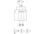
- FIG. 1 is a diagram showing an example of a servo system according to an embodiment.
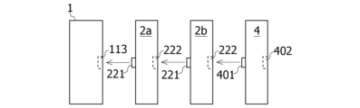
- FIG. 2 is a diagram schematically showing connections between a converter unit, an inverter unit, and an option unit in the servo system according to the embodiment.
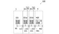
- FIG. 3 is a diagram illustrating a state in which a converter unit, an inverter unit, and an option unit are connected via an internal bus in the servo system according to the embodiment.
- FIG. 4 is a diagram showing a schematic configuration of functional units included in the control circuit of the converter unit.
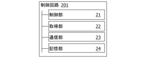
- FIG. 5 is a diagram showing a schematic configuration of functional sections included in the control circuit of the inverter unit.
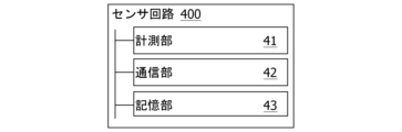
- FIG. 6 is a diagram showing a schematic configuration of a functional section included in the sensor circuit of the option unit.
- FIG. 1 is a diagram showing an example of a servo system according to an embodiment.
- FIG. 2 is a diagram schematically showing connections between a converter unit, an inverter unit, and an option unit in the servo system
- FIG. 7 is a diagram showing an example of a processing flow for detecting a unit newly connected to an internal bus in a servo system.
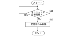
- FIG. 8 is a diagram showing an example of a processing flow for detecting removal of a unit connected to an internal bus in a servo system.
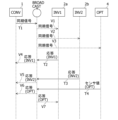
- FIG. 9 is a diagram showing an example of a communication sequence using an internal bus in a servo system.
- FIG. 1 is a diagram showing an example of a servo system 100 according to an embodiment.
- the servo system 100 includes a converter unit 1, an inverter unit 2a, an inverter unit 2b, and an option unit 4.
- a servo motor 3a is connected to the inverter unit 2a
- a servo motor 3b is connected to the inverter unit 2b.
- the inverter unit 2a and the inverter unit 2b are not distinguished, they are also referred to as the inverter unit 2.
- the servo motor 3a and the servo motor 3b are not distinguished, they are also referred to as the servo motor 3.
- a PLC 5 is connected to the servo system 100 via an industrial network N1.
- the PLC 5 outputs command signals to the converter unit 1 and inverter unit 2 of the servo system 100 via the industrial network N1.
- the PLC 5 functions, for example, as a monitoring device for the servo system 100 by executing processing according to a program prepared in advance.
- the industrial network N1 is, for example, a TCP/IP network.
- the PLC 5 is an example of a "superior device”.
- the industrial network N1 is an example of "wiring".
- the servo system 100 is a building block type servo system including a converter unit 1 and a plurality of inverter units 2.
- a plurality of inverter units 2 can be connected to one converter unit 1, and the inverter unit 2 connected to the converter unit 1 can be separated from the converter unit 1.
- the servo system 100 includes three inverter units 2, but the number of inverter units 2 may be two or less, or four or more.
- Converter unit 1 and inverter unit 2 receive command signals from PLC 5 via industrial network N1.
- Converter unit 1 distributes current received from a power source (not shown) to inverter unit 2 .
- Converter unit 1 is an example of a "management unit.”
- the inverter unit 2 receives current from the converter unit 1 and supplies drive current to the servo motor 3. Inverter unit 2 receives a feedback signal from servo motor 3. Each inverter unit 2 has a servo system that performs feedback control using a position controller, speed controller, current controller, etc. These signals are used to servo control the servo motor 3. Drive. Furthermore, the inverter unit 2 uses sensor values provided from the option unit 4 for servo control of the servo motor 3. Inverter unit 2 is an example of a "control unit.”
- the servo motor 3 is, for example, an AC servo motor.
- the servo motor 3 operates in response to drive current supplied from the inverter unit 2 .
- the servo motor 3 detects the displacement of the output shaft of the servo motor 3 and outputs a feedback signal indicating the detected displacement to the inverter unit 2.
- the servo motor 3 is an example of an "electric motor.”
- the option unit 4 is a unit having sensors such as a temperature sensor, a pressure sensor, a fully closed sensor, and the like.
- the option unit 4 provides the inverter unit 2 with sensor values detected by the sensors.
- Option unit 4 is an example of an "option unit.”
- FIG. 2 is a diagram schematically showing the connections of the converter unit 1, inverter unit 2, and option unit 4 in the servo system 100 according to the embodiment.
- a female type other unit connection port 113 is provided on the side surface of the converter unit 1 .
- a male upstream connection terminal 221 is provided on the side surface of the inverter unit 2 on the converter unit 1 side (upstream side).
- a female downstream connection port 222 is provided on the side surface of the inverter unit 2 on the opposite side (downstream side) from the converter unit 1 side.
- An upstream connection terminal 401 is provided on the upstream side surface of the option unit 4.
- a downstream connection port 402 is provided on the downstream side of the option unit 4.
- FIG. 3 is a diagram illustrating a state in which the converter unit 1, inverter unit 2, and option unit 4 are connected via the internal bus B1 in the servo system 100 according to the embodiment.
- a control circuit 101 that controls the supply of current to the inverter unit 2 and the exchange of information with the inverter unit 2 is connected to an internal bus B1.
- a control circuit 201a that controls the servo motor 3a is connected to the internal bus B1.
- a control circuit 201b that controls the servo motor 3b is connected to the internal bus B1.
- the control circuit 201a and the control circuit 201b are not distinguished, they are also referred to as the control circuit 201.
- a sensor circuit 400 that outputs a sensor value detected by the sensor is connected to the internal bus B1.
- Internal bus B1 is an example of a "bus”.
- the internal bus B1 is a multi-drop type bus that connects units. Data output by a certain unit connected to internal bus B1 can be received by all other units connected to internal bus B1. That is, the units connected to the internal bus B1 output data by broadcast to the internal bus B1. Examples of the internal bus B1 include RS-485 and CAN buses.
- the internal bus B1 of the converter unit 1, inverter unit 2, and option unit 4 is connected.
- the control circuit 101 is connected to the internal bus B1
- the sensor circuit 400 can output a sensor value detected by the sensor to the control circuit 201 by being connected to the internal bus B1.
- the sensor circuit 400 outputs sensor values to the internal bus B1 by broadcasting.
- FIG. 4 is a diagram showing a schematic configuration of functional sections included in control circuit 101 of converter unit 1.
- the control circuit 101 can be regarded as a computer having an arithmetic unit, a storage device, and the like.
- the functional units shown in FIG. 4 are realized by executing a predetermined program or the like in the control circuit 101.
- the control circuit 101 includes a communication control unit 11, a power supply unit 12, a management unit 13, and a storage unit 14, but may include functional units other than these.
- the communication control unit 11 outputs a synchronization signal that triggers the start of communication to the inverter unit 2 and option unit 4 that communicate using the internal bus B1.
- the power supply section 12 converts an alternating current supplied from an external power source into a direct current, and supplies the DC current to the inverter unit 2 .
- the synchronization signal is an example of a "first signal.”
- the management unit 13 detects a unit newly connected to the internal bus B1 based on the response to the synchronization signal from the inverter unit 2 and the option unit 4.
- the management unit 13 assigns a unique ID among the units connected to the internal bus B1 to the detected new unit.
- the management unit 13 allocates IDs such that, for example, units connected to the upstream side are assigned a lower number.
- the assigned ID is stored in the storage unit 14 in association with, for example, the serial number of the unit included in the response that transmitted the response.
- the management unit 13 detects that the unit has been removed from the servo system 100. For example, the ID assigned to the unit whose removal was detected is deleted from the storage unit 14.
- ID is an example of an "identification number.”
- the storage unit 14 stores IDs assigned to the inverter unit 2 and option units 4 by the management unit 13 and information related to processing performed by the control circuit 101.
- the storage unit 14 is, for example, an EEPROM.
- FIG. 5 is a diagram showing a schematic configuration of functional sections included in the control circuit 201 of the inverter unit 2.
- the control circuit 201 can be considered as a computer having an arithmetic unit, a storage device, and the like.
- the functional units shown in FIG. 5 are realized by executing a predetermined program or the like in the control circuit 201.
- the control circuit 201 includes a control section 21, an acquisition section 22, a communication section 23, and a storage section 24, but may include functional sections other than these.
- the control unit 21 servo-controls the servo motor 3 according to instructions from the PLC 5.
- sensor values acquired by the acquisition unit 22 may be used.
- the acquisition unit 22 acquires sensor values output by broadcast from the option unit 4 via the internal bus B1.
- the acquisition unit 22 stores the ID of the option unit 4 designated by the user or the like in the storage unit 24, and acquires the sensor value transmitted from the option unit 4 with the ID stored in the storage unit 24. Good too.
- the communication section 23 outputs a response signal according to the synchronization signal from the converter unit 1 to the converter unit 1 via the internal bus B1.
- the response signal may include, for example, the serial number of the own unit.
- the communication section 23 may determine the transmission timing of the response signal based on the ID assigned to the inverter unit 2. For example, the communication unit 23 may transmit the response signal after a time period obtained by multiplying the ID assigned to the own unit by a predetermined response time after receiving the synchronization signal.
- the predetermined response time may be stored in the storage unit 24 in advance, for example.
- the storage unit 24 stores information related to the processing performed by the control circuit 201.
- the storage unit 24 is, for example, a nonvolatile storage unit such as an EEPROM.
- FIG. 6 is a diagram showing a schematic configuration of functional units included in the sensor circuit 400 of the option unit 4.
- the sensor circuit 400 can be regarded as a computer having a calculation device, a storage device, and the like.
- the functional units shown in FIG. 6 are realized by executing a predetermined program or the like in the sensor circuit 400.
- the sensor circuit 400 includes a measurement section 41, a communication section 42, and a storage section 43, but may include functional sections other than these.
- the measurement unit 41 performs measurement using a sensor included in the option unit 4. For example, if the sensor included in the option unit 4 is a temperature sensor, the measurement unit 41 measures the temperature. Further, for example, if the sensor included in the option unit 4 is a pressure sensor, the measurement unit 41 measures pressure.
- Option unit 4 may include multiple sensors. When the optional unit 4 has a plurality of sensors, the measurement section 41 may perform measurement using each sensor.
- the communication unit 42 transmits the sensor value measured by the measurement unit 41 via the internal bus B1 in response to the synchronization signal from the converter unit 1. Transmission via the internal bus B1 is performed by broadcast, as described above.
- the serial number of the optional unit 4 may be attached to the sensor value.
- the communication unit 42 may determine the transmission timing of the response signal based on the ID assigned to its own unit. For example, the communication unit 42 may transmit the sensor value to the internal bus B1 after a time period obtained by multiplying the ID assigned to the own unit by a predetermined response time after receiving the synchronization signal.
- the predetermined response time may be stored in the storage unit 43 in advance, for example.
- the communication unit 42 may further transmit the sensor value to the PLC 5 via the industrial network N1. Transmission via the industrial network N1 may be performed by specifying the PLC 5 as the destination device.
- the storage unit 43 stores information related to the processing performed by the sensor circuit 400.
- the storage unit 43 is, for example, a nonvolatile storage unit such as an EEPROM.
- FIG. 7 is a diagram showing an example of a processing flow for detecting a unit newly connected to the internal bus B1 in the servo system 100.
- An example of a processing flow for detecting a unit newly connected to the internal bus B1 will be described below with reference to FIG. 7. It is assumed that the communication control section 11 of the converter unit 1 outputs a synchronization signal to the internal bus B1 at predetermined intervals.
- the management section 13 of the converter unit 1 determines whether or not a response to the synchronization signal outputted by the communication control section 11 at predetermined intervals has been received. If received (YES in S1), the process proceeds to S2. If not received (YES in S2), the process proceeds to S1.
- the management unit 13 determines whether the response received in S1 is a response from a unit to which no ID has been assigned. The management unit 13 determines whether the response is from a unit to which no ID has been assigned, based on whether the serial number included in the response received in S1 is stored in the storage unit 14, for example. If the response is from a unit to which no ID has been assigned (YES in S2), the process proceeds to S3. If the response is not from a unit to which no ID has been assigned (NO in S2), the process proceeds to S1.
- the management unit 13 assigns an ID to the source unit of the response received by the converter unit 1. For example, the management unit 13 associates the assigned ID with the serial number included in the response received in S1 and causes the storage unit 14 to store the associated ID.
- FIG. 8 is a diagram showing an example of a processing flow for detecting removal of a unit connected to the internal bus B1 in the servo system 100.
- An example of a processing flow for detecting removal of a unit connected to internal bus B1 in servo system 100 will be described below with reference to FIG. 8. It is assumed that the communication control section 11 of the converter unit 1 outputs a synchronization signal to the internal bus B1 at predetermined intervals.
- the management unit 13 determines whether responses to the synchronization signal have been confirmed from all units to which IDs have been assigned. If responses from all units to which IDs have been assigned are confirmed (YES in S11), the process in S11 is repeated. If responses from at least some of the ID-assigned units are not confirmed (NO in S11), the process proceeds to S12.
- the management unit 13 deletes from the storage unit 14 the ID of the unit whose response was not confirmed in S11.
- FIG. 9 is a diagram showing an example of a communication sequence using the internal bus B1 in the servo system 100.
- an ID is assigned to each unit.
- An example of a communication sequence using internal bus B1 in servo system 100 will be described below with reference to FIG.
- the inverter unit 2a uses the sensor value from the option unit 4.
- FIG. 9 it is assumed that time passes from top to bottom.
- the converter unit 1 is written as "CONV”
- the inverter unit 2a is written as "INV1”
- the inverter unit 2b is written as "INV2”
- the option unit 4 is written as "OPT”.
- solid line arrows illustrate actual signal transmission.
- a solid arrow with "BROADCAST” at the end exemplifies a signal transmitted by broadcast.
- the dotted arrow extending from the broadcast exemplifies the receiving destination of the signal transmitted by the broadcast.
- the converter unit 1 broadcasts a synchronization signal to the internal bus B1.
- the synchronization signal broadcasted at T1 is received by the inverter unit 2a, the inverter unit 2b, and the option unit 4, as exemplified by V1, V2, and V3.
- the inverter unit 2a broadcasts a response to the synchronization signal transmitted at T1 to the internal bus B1.
- the response broadcasted at T2 is received by the converter unit 1, as illustrated at V4.
- the inverter unit 2b broadcasts a response to the synchronization signal transmitted at T1 to the internal bus B1.
- the response broadcasted at T3 is received by the converter unit 1, as illustrated at V5.
- the option unit 4 broadcasts the sensor value to the internal bus B1 in response to the synchronization signal transmitted at T1.
- the sensor values broadcasted at T4 are received by the converter unit 1 and the inverter unit 2a, as illustrated at V6 and V7.
- both the inverter unit 2 and the option unit 4 are connected to the internal bus B1.
- the data output to the internal bus B1 is then transmitted by broadcast. Therefore, the option unit 4 can transmit sensor values to both inverter units 2a and 2b even if it is placed at any position. Therefore, according to this embodiment, the option unit 4 including the sensor can be connected to the servo system 100 more flexibly.
- the converter unit 1 assigns different IDs to each of the inverter unit 2 and the option unit 4. Therefore, according to this embodiment, each unit can be uniquely identified. Further, according to the present embodiment, the ID of the option unit 4 is attached to the sensor value transmitted from the option unit 4, so that the inverter unit 2 can use the sensor value sent from the desired option unit 4. The servo motor 3 can be controlled.
- the inverter unit 2 and the option unit 4 after receiving the synchronization signal from the converter unit 1, the inverter unit 2 and the option unit 4 output a response after delaying by a delay time according to the assigned ID.
- Such a configuration prevents a plurality of units from simultaneously outputting responses to the internal bus B1. Furthermore, since it is possible to suppress the occurrence of collisions on the internal bus B1, a decrease in communication efficiency of communication using the internal bus B1 is suppressed.
- the converter unit 1 detects the removal of that unit from the servo system 100 (or internal bus B1). Furthermore, upon receiving a response to the synchronization signal from a unit to which no ID has been assigned, converter unit 1 detects the connection of that unit to servo system 100 . That is, according to the present embodiment, connection and disconnection of units can be easily detected without any additional work by the user.
- the option unit 4 is connected to the PLC 5 via the industrial network N1.
- the option unit 4 can output the sensor value to the PLC 5 via the industrial network N1. Therefore, according to this embodiment, for example, it is possible to cause the PLC 5 to monitor the servo system 100 including changes in sensor values.
- the converter unit 1 may set priorities to the inverter unit 2 and the option unit 4. Then, the inverter unit 2 and the option unit 4 may determine the response frequency to the synchronization signal according to the set priority. For example, a unit set with a high priority may transmit a response every time it receives a synchronization signal. Further, for example, a unit to which a low priority is set only needs to transmit a response once when receiving a synchronization signal twice. By setting the frequency of responses to the synchronization signal in accordance with the priority in this manner, it is possible to effectively use the internal bus B1 for units that prefer to transmit responses at a high frequency.
Landscapes
- Engineering & Computer Science (AREA)
- Power Engineering (AREA)
- Control Of Multiple Motors (AREA)
Abstract
検出したセンサ値を出力するオプションユニットをより柔軟に接続することができるサーボシステムを提供する。本サーボシステムは、接続された電動機を制御する複数の制御ユニットと、複数の上記制御ユニットを相互に通信可能に接続するバスと、を含み、上記バスには、上記電動機の制御に係るセンサ値を複数の上記制御ユニットに対してブロードキャストで送信するオプションユニットが着脱可能に接続される。
Description
本発明は、サーボシステムに関する。
サーボシステムにおけるサーボ制御では、モータからのフィードバック信号に加えて、フルクローズドセンサや圧力センサ等の各種センサの検出値が利用される(例えば、特許文献1、2参照)。
近年では、交流電力を直流電力に出力するコンバータユニットに対し、モータを制御するインバータユニットを複数接続する、いわゆるビルディングブロック形式のサーボシステムも利用されている。このようなビルディングブロック形式のサーボシステムに対して、各種センサに例示されるオプションユニットを接続することも考えられる。しかしながら、オプションユニットとインバータユニットとは1対1で接続されることから、オプションユニットの配置において柔軟性に欠けていた。
開示の技術の1つの側面は、検出したセンサ値を出力するオプションユニットをより柔軟に接続することができるサーボシステムを提供することを目的とする。
開示の技術の1つの側面は、次のようなサーボシステムによって例示される。本サーボシステムは、接続された電動機を制御する複数の制御ユニットと、複数の上記制御ユニットを相互に通信可能に接続するバスと、を含み、上記バスには、上記電動機の制御に係るセンサ値を複数の上記制御ユニットに対してブロードキャストで送信するオプションユニットが着脱可能に接続される。
上記サーボシステムでは、制御ユニット及びオプションユニットはいずれもバスに接続される。そして、オプションユニットは、上記バスを介してブロードキャストでセンサ値を出力する。そのため、オプションユニットは、バス上の任意に位置に配置されても複数の制御ユニットの何れに対してもセンサ値を送信することができる。そのため、上記サーボシステムによれば、オプションユニットをサーボシステムに対してより柔軟に接続することができる。
上記サーボシステムは、次の特徴を備えてもよい。上記バスに接続され、上記複数の制御ユニット及び上記オプションユニットの夫々に対して、互いに異なる識別番号を割り当てる管理ユニットをさらに備える。上記サーボシステムによれば、バスに接続された各ユニットを一意に識別することができる。
上記サーボシステムは、次の特徴を備えてもよい。上記オプションユニットは、上記管理ユニットによって割り当てられた上記識別番号を付して上記センサ値をブロードキャストで送信し、上記複数の制御ユニットには、取得する上記センサ値の送信元となる上記オプションユニットの上記識別番号が指定されており、上記複数の制御ユニットは、上記指定された識別番号が付された上記センサ値を取得し、取得した上記センサ値を用いて上記電動機を制御する。上記サーボシステムによれば、オプションユニットに識別番号が付されるので、制御ユニットは、当該識別番号を用いて所望のオプションユニットが送信元であるセンサ値を用いて電動機を制御することができる。
上記サーボシステムは、次の特徴を備えてもよい。上記管理ユニットは、上記バスを介して第1信号をブロードキャストで送信し、上記複数の制御ユニットの夫々は、上記第1信号を受信すると、自ユニットに割り当てられた識別番号を基に決定された遅延時間が経過してから、上記第1信号に対する応答を上記バスを介してブロードキャストで送信し、上記オプションユニットは、上記第1信号を受信すると、上記識別番号を基に決定された遅延時間が経過してから、上記第1信号に対する応答として上記センサ値を上記バスを介してブロードキャスト送信する。各ユニットに対して互いに異なるように割り当てられた識別番号を基に遅延時間が決定されるので、複数のユニットからバスに対して同時に上記応答が出力されることが抑制される。ひいては、バス上でのコリジョンの発生を抑制することができるため、バスを利用した通信の通信効率低下が抑制される。
上記サーボシステムは、次の特徴を備えてもよい。上記管理ユニットは、上記複数の制御ユニット及び上記オプションユニットのうち、上記第1信号に対する応答がないユニットが上記バスから取り外されたと認識する。上記サーボシステムは、このような特徴を備えることで、ユーザによる追加の作業無しに、ユニットのバスからの取り外しを認識することができる。
上記サーボシステムは、次の特徴を備えてもよい。上記管理ユニットは、上記複数の制御ユニット及び上記オプションユニットに対して優先度を設定し、上記複数の制御ユニット及び上記オプションユニットの夫々は、設定された上記優先度に応じた頻度で上記第1信号に対する上記応答を送信する。上記サーボシステムは、このような特徴を備えることで、高い優先度が設定されたユニットに対して優先的にバスを用いた通信を実行させることができる。
上記サーボシステムは、次の特徴を備えてもよい。上記複数の制御ユニットと上記オプションユニットは、上記複数の制御ユニットに対して上記電動機を駆動させる指令を出力する上位装置と、上記バスとは異なる配線で接続され、上記複数の制御ユニットは、上記配線を介して上記上位装置から受ける指令にしたがって上記電動機を駆動し、上記オプションユニットは、上記センサ値を上記配線を介して上記上位装置にも送信する。上記サーボシステムは、このような特徴を備えることで、センサ値の変動を含むサーボシステムの監視を上記上位装置に行わせることができる。
開示の技術によれば、センサを含むオプションユニットをより柔軟に接続することができるサーボシステムを提供することができる。
<実施形態>
以下、図面を参照して実施形態に係るサーボシステムについて説明する。図1は、実施形態に係るサーボシステム100の一例を示す図である。サーボシステム100は、コンバータユニット1、インバータユニット2a、インバータユニット2b及びオプションユニット4を含む。インバータユニット2aにはサーボモータ3aが接続され、インバータユニット2bにはサーボモータ3bが接続される。インバータユニット2a、インバータユニット2bを区別しない場合、インバータユニット2とも称する。また、サーボモータ3a、サーボモータ3bを区別しない場合、サーボモータ3とも称する。サーボシステム100には、産業用ネットワークN1によってPLC5が接続される。
以下、図面を参照して実施形態に係るサーボシステムについて説明する。図1は、実施形態に係るサーボシステム100の一例を示す図である。サーボシステム100は、コンバータユニット1、インバータユニット2a、インバータユニット2b及びオプションユニット4を含む。インバータユニット2aにはサーボモータ3aが接続され、インバータユニット2bにはサーボモータ3bが接続される。インバータユニット2a、インバータユニット2bを区別しない場合、インバータユニット2とも称する。また、サーボモータ3a、サーボモータ3bを区別しない場合、サーボモータ3とも称する。サーボシステム100には、産業用ネットワークN1によってPLC5が接続される。
PLC5は、サーボシステム100のコンバータユニット1及びインバータユニット2に対する指令信号を産業用ネットワークN1を介して出力する。PLC5は、予め準備されたプログラムに従う処理を実行することによって、例えば、サーボシステム100の監視装置として機能する。産業用ネットワークN1は、例えば、TCP/IPネットワークである。PLC5は、「上位装置」の一例である。産業用ネットワークN1は、「配線」の一例である。
サーボシステム100は、コンバータユニット1及び複数のインバータユニット2を含むビルディングブロック形式のサーボシステムである。サーボシステム100では、1台のコンバータユニット1に対して複数のインバータユニット2を接続することや、コンバータユニット1に接続したインバータユニット2をコンバータユニット1から切り離すことができる。図1では、サーボシステム100は3台のインバータユニット2を含むが、インバータユニット2の数は2台以下でもよいし、4台以上であってもよい。
コンバータユニット1及びインバータユニット2は、産業用ネットワークN1を介してPLC5から指令信号を受ける。コンバータユニット1は、図示しない電源から受けた電流をインバータユニット2に分配する。コンバータユニット1は、「管理ユニット」の一例である。
インバータユニット2は、コンバータユニット1から電流の供給を受けてサーボモータ3に駆動電流を供給する。インバータユニット2は、サーボモータ3からフィードバック信号を受ける。インバータユニット2においては、それぞれ、位置制御器、速度制御器、電流制御器等を利用したフィードバック制御を行うサーボ系が形成されており、これらの信号を利用して、サーボモータ3をサーボ制御し駆動する。また、インバータユニット2は、オプションユニット4から提供されるセンサ値をサーボモータ3のサーボ制御に利用する。インバータユニット2は、「制御ユニット」の一例である。
サーボモータ3は、例えば、ACサーボモータである。サーボモータ3は、インバータユニット2から給電された駆動電流を受けて動作する。サーボモータ3は、サーボモータ3の出力軸の変位を検出し、検出した変位を示すフィードバック信号をインバータユニット2に出力する。サーボモータ3は、「電動機」の一例である。
オプションユニット4は、温度センサ、圧力センサ、フルクローズドセンサ等によって例示されるセンサを有するユニットである。オプションユニット4は、センサによって検出したセンサ値をインバータユニット2に提供する。オプションユニット4は、「オプションユニット」の一例である。
図2は、実施形態に係るサーボシステム100におけるコンバータユニット1、インバータユニット2及びオプションユニット4の接続を模式的に示す図である。コンバータユニット1の側面には、メス型の他ユニット接続ポート113が設けられる。インバータユニット2のコンバータユニット1側(上流側)の側面にはオス型の上流側接続端子221が設けられる。また、インバータユニット2のコンバータユニット1側とは反対側(下流側)の側面には、メス型の下流側接続ポート222が設けられる。オプションユニット4の上流側の側面には上流側接続端子401が設けられる。また、オプションユニット4の下流側の側面には下流側接続ポート402が設けられる。
コンバータユニット1の他ユニット接続ポート113とインバータユニット2aの上流側接続端子221とが接続され、インバータユニット2aの下流側接続ポート222とインバータユニット2bの上流側接続端子221とが接続される。そして、インバータユニット2bの下流側接続ポート222にはオプションユニット4の上流側接続端子401が接続される。そして、ビルディングブロック形式のサーボシステム100では、このように各ユニットの接続端子及び接続ポートが接続されることで、コンバータユニット1、インバータユニット2及びオプションユニット4が互いに着脱可能に接続される。
図3は、実施形態に係るサーボシステム100において、コンバータユニット1、インバータユニット2及びオプションユニット4が内部バスB1で接続される状態を例示する図である。コンバータユニット1では、インバータユニット2への電流の供給やインバータユニット2との情報の授受を制御する制御回路101が内部バスB1に接続される。インバータユニット2aでは、サーボモータ3aを制御する制御回路201aが内部バスB1に接続される。インバータユニット2bでは、サーボモータ3bを制御する制御回路201bが内部バスB1に接続される。制御回路201a、制御回路201bを区別しない場合、制御回路201とも称する。そして、オプションユニット4では、センサによって検出されたセンサ値を出力するセンサ回路400が内部バスB1に接続される。内部バスB1は、「バス」の一例である。
内部バスB1は、マルチドロップ型でユニット間を接続するバスである。内部バスB1に接続されたあるユニットが出力したデータは、内部バスB1に接続された他の全てのユニットが受信可能となる。すなわち、内部バスB1に接続されたユニットは、内部バスB1に対してブロードキャストでデータを出力する。内部バスB1としては、例えば、RS-485、CANバス等を挙げることができる。
サーボシステム100では、図2に例示するようにコンバータユニット1、インバータユニット2及びオプションユニット4が接続されることで、コンバータユニット1、インバータユニット2及びオプションユニット4の内部バスB1が接続される。制御回路101は、内部バスB1が接続されることで、制御回路201への電流の供給や、制御回路201との情報の授受が可能となる。また、センサ回路400は、内部バスB1が接続されることで、制御回路201に対してセンサによって検出されたセンサ値を出力できる。上記の通り、内部バスB1がマルチドロップ型のバスであることから、センサ回路400は内部バスB1に対してブロードキャストでセンサ値を出力する。
<コンバータユニット1の機能部>
図4は、コンバータユニット1の制御回路101が有する機能部の概略構成を示す図である。制御回路101は、演算装置、記憶装置等を有するコンピュータとみなすことができる。図4に示す機能部は、制御回路101において所定のプログラム等が実行されることで実現される。制御回路101は、通信制御部11、給電部12、管理部13及び記憶部14を有するが、これら以外の機能部を有していても構わない。
図4は、コンバータユニット1の制御回路101が有する機能部の概略構成を示す図である。制御回路101は、演算装置、記憶装置等を有するコンピュータとみなすことができる。図4に示す機能部は、制御回路101において所定のプログラム等が実行されることで実現される。制御回路101は、通信制御部11、給電部12、管理部13及び記憶部14を有するが、これら以外の機能部を有していても構わない。
通信制御部11は、内部バスB1を利用した通信を行うインバータユニット2及びオプションユニット4に対して、通信開始の契機とする同期信号を出力する。給電部12は、外部の電源から供給された交流電流を直流電流に変換してインバータユニット2に供給する。同期信号は、「第1信号」の一例である。
管理部13は、インバータユニット2やオプションユニット4からの同期信号に対する応答を基に、内部バスB1に新たに接続されたユニットを検出する。管理部13は、検出した新たなユニットに対して、内部バスB1に接続されたユニット間でユニークなIDを割り当てる。管理部13は、例えば、上流側に接続されたユニット程若い番号が割り当てられるように、IDの割り当てを行う。割り当てられたIDは、例えば、応答に含まれる当該応答を送信したユニットのシリアル番号等に対応付けて記憶部14に記憶される。また、管理部13は、ID割り当て済みのユニットから同期信号に対する応答がなかった場合には、当該ユニットのサーボシステム100からの取り外しを検出する。取り外しが検出されたユニットに割り当てられていたIDは、例えば、記憶部14から削除される。IDは、「識別番号」の一例である。
記憶部14は、管理部13によってインバータユニット2やオプションユニット4に割り当てられたIDや、制御回路101で行われる処理に関連する情報を記憶する。記憶部14は、例えば、EEPROMである。
<インバータユニット2の機能部>
図5は、インバータユニット2の制御回路201が有する機能部の概略構成を示す図である。制御回路201は、演算装置、記憶装置等を有するコンピュータとみなすことができる。図5に示す機能部は、制御回路201において所定のプログラム等が実行されることで実現される。制御回路201は、制御部21、取得部22、通信部23及び記憶部24を有するが、これら以外の機能部を有していても構わない。
図5は、インバータユニット2の制御回路201が有する機能部の概略構成を示す図である。制御回路201は、演算装置、記憶装置等を有するコンピュータとみなすことができる。図5に示す機能部は、制御回路201において所定のプログラム等が実行されることで実現される。制御回路201は、制御部21、取得部22、通信部23及び記憶部24を有するが、これら以外の機能部を有していても構わない。
制御部21は、PLC5からの指令にしたがって、サーボモータ3をサーボ制御する。制御部21によるサーボ制御では、例えば、取得部22によって取得されたセンサ値が利用されてもよい。
取得部22は、オプションユニット4から内部バスB1を介してブロードキャストで出力されるセンサ値を取得する。取得部22は、例えば、ユーザ等によって指定されたオプションユニット4のIDを記憶部24に記憶しておき、記憶部24に記憶されたIDのオプションユニット4から送信されたセンサ値を取得してもよい。
通信部23は、コンバータユニット1からの同期信号に応じた応答信号を内部バスB1を介してコンバータユニット1に対して出力する。応答信号には、例えば、自ユニットのシリアル番号を含めてもよい。通信部23は、インバータユニット2に割り当てられたIDに基づいて応答信号の送信タイミングを決定してもよい。通信部23は、例えば、同期信号を受信してから、自ユニットに割り当てられたIDと所定の応答時間とを乗じた時間の経過後に、応答信号を送信してもよい。所定の応答時間は、例えば、予め記憶部24に記憶されればよい。
記憶部24は、制御回路201で行われる処理に関連する情報を記憶する。記憶部24は、例えば、EEPROM等の不揮発性の記憶部である。
<オプションユニット4の機能部>
図6は、オプションユニット4のセンサ回路400が有する機能部の概略構成を示す図である。センサ回路400は、演算装置、記憶装置等を有するコンピュータとみなすことができる。図6に示す機能部は、センサ回路400において所定のプログラム等が実行されることで実現される。センサ回路400は、計測部41、通信部42及び記憶部43を有するが、これら以外の機能部を有していても構わない。
図6は、オプションユニット4のセンサ回路400が有する機能部の概略構成を示す図である。センサ回路400は、演算装置、記憶装置等を有するコンピュータとみなすことができる。図6に示す機能部は、センサ回路400において所定のプログラム等が実行されることで実現される。センサ回路400は、計測部41、通信部42及び記憶部43を有するが、これら以外の機能部を有していても構わない。
計測部41は、オプションユニット4が有するセンサによる計測を行う。例えば、オプションユニット4が有するセンサが温度センサである場合には、計測部41は温度の計測を行う。また、例えば、オプションユニット4が有するセンサが圧力センサである場合には、計測部41は圧力の計測を行う。オプションユニット4は複数のセンサを有してもよい。オプションユニット4が複数のセンサを有する場合、計測部41は夫々のセンサによる計測を行えばよい。
通信部42は、コンバータユニット1からの同期信号に応じて、計測部41によって計測されたセンサ値を内部バスB1を介して送信する。内部バスB1を介した送信は、上記の通り、ブロードキャストで行われる。センサ値には、例えば、オプションユニット4のシリアル番号を付してもよい。
通信部42は、自ユニットに割り当てられたIDに基づいて応答信号の送信タイミングを決定してもよい。通信部42は、例えば、同期信号を受信してから、自ユニットに割り当てられたIDと所定の応答時間とを乗じた時間の経過後に、センサ値を内部バスB1に送信してもよい。所定の応答時間は、例えば、予め記憶部43に記憶されればよい。
通信部42は、さらに、産業用ネットワークN1を介してセンサ値をPLC5に対して送信してもよい。産業用ネットワークN1を介した送信は、宛先装置であるPLC5を指定して行われてもよい。
記憶部43は、センサ回路400で行われる処理に関連する情報を記憶する。記憶部43は、例えば、EEPROM等の不揮発性の記憶部である。
図7は、サーボシステム100において、新たに内部バスB1に接続されたユニットを検出する処理フローの一例を示す図である。以下、図7を参照して、新たに内部バスB1に接続されたユニットを検出する処理フローの一例について説明する。なお、コンバータユニット1の通信制御部11は、所定間隔で同期信号を内部バスB1に対して出力しているものとする。
S1では、コンバータユニット1の管理部13は、通信制御部11によって所定間隔で出力される同期信号に対する応答を受信したか否かを判定する。受信した場合(S1でYES)、処理はS2に進められる。受信しない場合(S2でYES)、処理はS1に進められる。
S2では、管理部13は、S1で受信した応答がID未割当のユニットからの応答であるか否かを判定する。管理部13は、例えば、S1で受信した応答に含まれるシリアル番号が記憶部14に記憶されているか否かに基づいて、ID未割当のユニットからの応答であるか否かを判定する。ID未割当のユニットからの応答である場合(S2でYES)、処理はS3に進められる。ID未割当のユニットからの応答ではない場合(S2でNO)、処理はS1に進められる。
S3では、管理部13は、コンバータユニット1で受信した応答の送信元ユニットに対してIDを割り当てる。管理部13は、例えば、割り当てたIDとS1で受信した応答に含まれるシリアル番号とを対応付けて記憶部14に記憶させる。
図8は、サーボシステム100において、内部バスB1に接続されたユニットの取り外しを検出する処理フローの一例を示す図である。以下、図8を参照して、サーボシステム100において、内部バスB1に接続されたユニットの取り外しを検出する処理フローの一例について説明する。なお、コンバータユニット1の通信制御部11は、所定間隔で同期信号を内部バスB1に対して出力しているものとする。
S11では、管理部13は、ID割り当て済みの全ユニットから、同期信号に対する応答が確認されたか否かを判定する。ID割り当て済みの全ユニットからの応答が確認された場合(S11でYES)、S11の処理が繰り返される。ID割り当て済みのユニットのうち少なくとも一部のユニットの応答が確認されなかった場合(S11でNO)、処理はS12に進められる。
S12では、管理部13は、S11で応答が確認されなかったユニットのIDを記憶部14から削除する。
図9は、サーボシステム100における内部バスB1を利用した通信シーケンスの一例を示す図である。図9では、各ユニットに対してIDが割り当てられた状態であるものとする。以下、図9を参照して、サーボシステム100における内部バスB1を利用した通信シーケンスの一例について説明する。なお、図9の例では、インバータユニット2のうち、インバータユニット2aがオプションユニット4からのセンサ値を利用するものとする。
図9では、上から下に向けて時間が経過するものとする。図9では、コンバータユニット1は「CONV」、インバータユニット2aは「INV1」、インバータユニット2bは「INV2」、オプションユニット4は「OPT」と記載される。また、図9において、実線の矢印は実際の信号の送信を例示する。そして、実線の矢印の先が「BROADCAST」であるものは、ブロードキャストで送信された信号を例示する。また、ブロードキャストから延びる点線の矢印は、ブロードキャストで送信された信号の受信先を例示する。
T1では、コンバータユニット1は、内部バスB1に対してブロードキャストで同期信号を送信する。T1においてブロードキャストで送信された同期信号は、V1、V2、V3で例示するように、インバータユニット2a、インバータユニット2b、オプションユニット4に受信される。
T2では、インバータユニット2aは、T1で送信された同期信号に対する応答を内部バスB1に対してブロードキャストで送信する。T2においてブロードキャストで送信された応答は、V4で例示するように、コンバータユニット1によって受信される。
T3では、インバータユニット2bは、T1で送信された同期信号に対する応答を内部バスB1に対してブロードキャストで送信する。T3においてブロードキャストで送信された応答は、V5で例示するように、コンバータユニット1によって受信される。
T4では、オプションユニット4は、T1で送信された同期信号に対する応答としてセンサ値を内部バスB1に対してブロードキャストで送信する。T4においてブロードキャストで送信されたセンサ値は、V6及びV7で例示するように、コンバータユニット1及びインバータユニット2aによって受信される。
<実施形態の作用効果>
本実施形態では、インバータユニット2及びオプションユニット4はいずれも内部バスB1に接続される。そして、内部バスB1に出力されるデータは、ブロードキャストで送信される。そのため、オプションユニット4は、任意の位置に配置されてもインバータユニット2a、2bの何れに対してもセンサ値を送信することができる。そのため、本実施形態によれば、センサを含むオプションユニット4をサーボシステム100に対してより柔軟に接続することができる。
本実施形態では、インバータユニット2及びオプションユニット4はいずれも内部バスB1に接続される。そして、内部バスB1に出力されるデータは、ブロードキャストで送信される。そのため、オプションユニット4は、任意の位置に配置されてもインバータユニット2a、2bの何れに対してもセンサ値を送信することができる。そのため、本実施形態によれば、センサを含むオプションユニット4をサーボシステム100に対してより柔軟に接続することができる。
本実施形態では、コンバータユニット1は、インバータユニット2及びオプションユニット4の夫々に対して互いに異なるIDを割り当てる。そのため、本実施形態によれば、各ユニットを一意に識別することができる。また、本実施形態によれば、オプションユニット4から送信されるセンサ値にオプションユニット4のIDが付されることで、インバータユニット2は所望のオプションユニット4が送信元であるセンサ値を用いてサーボモータ3を制御することができる。
本実施形態では、コンバータユニット1からの同期信号を受信してから、インバータユニット2及びオプションユニット4は割り当てられたIDに応じた遅延時間だけ遅延させてから応答を出力する。このような構成により、複数のユニットから同時に内部バスB1に対して応答が出力されることが抑制される。ひいては、内部バスB1上でのコリジョンの発生を抑制することができるため、内部バスB1を利用した通信の通信効率低下が抑制される。
本実施形態では、コンバータユニット1は、ID割り当て済みにユニットのうち、同期信号に応答しないユニットが存在する場合、サーボシステム100(または内部バスB1)から当該ユニットの取り外しを検出する。また、コンバータユニット1は、ID未割当のユニットから同期信号に対する応答を受信すると、サーボシステム100への当該ユニットの接続を検出する。すなわち、本実施形態によれば、ユーザによる追加の作業が行われなくとも、ユニットの接続と取り外しを容易に検出することができる。
本実施形態では、オプションユニット4は産業用ネットワークN1によってPLC5と接続される。そして、オプションユニット4は、産業用ネットワークN1を介して、センサ値をPLC5に出力することができる。そのため、本実施形態によれば、例えば、センサ値の変動を含むサーボシステム100の監視をPLC5に実行させることができる。
<変形例>
コンバータユニット1は、インバータユニット2及びオプションユニット4に優先度を設定してもよい。そして、インバータユニット2及びオプションユニット4は、設定された優先度に応じて、同期信号に対する応答頻度を決定してもよい。例えば、高い優先度が設定されたユニットは同期信号を受信する度に応答を送信すればよい。また、例えば、低い優先度が設定されたユニットは、同期信号を2回受信すると応答を1回送信すればよい。このように優先度に応じて同期信号に対する応答の頻度が設定されることで、高頻度での応答の送信が好ましいユニットに対して有効に内部バスB1を利用させることができる。
コンバータユニット1は、インバータユニット2及びオプションユニット4に優先度を設定してもよい。そして、インバータユニット2及びオプションユニット4は、設定された優先度に応じて、同期信号に対する応答頻度を決定してもよい。例えば、高い優先度が設定されたユニットは同期信号を受信する度に応答を送信すればよい。また、例えば、低い優先度が設定されたユニットは、同期信号を2回受信すると応答を1回送信すればよい。このように優先度に応じて同期信号に対する応答の頻度が設定されることで、高頻度での応答の送信が好ましいユニットに対して有効に内部バスB1を利用させることができる。
<付記1>
接続された電動機(3)を制御する複数の制御ユニット(2)と、
複数の前記制御ユニット(2)を相互に通信可能に接続するバス(B1)と、を含み、
前記バス(B1)には、前記電動機(3)の制御に係るセンサ値を複数の前記制御ユニット(2)に対してブロードキャストで送信するオプションユニット(4)が着脱可能に接続される、
サーボシステム(100)。
接続された電動機(3)を制御する複数の制御ユニット(2)と、
複数の前記制御ユニット(2)を相互に通信可能に接続するバス(B1)と、を含み、
前記バス(B1)には、前記電動機(3)の制御に係るセンサ値を複数の前記制御ユニット(2)に対してブロードキャストで送信するオプションユニット(4)が着脱可能に接続される、
サーボシステム(100)。
1・・コンバータユニット
2・・インバータユニット
2a・・インバータユニット
2b・・インバータユニット
3・・サーボモータ
3a・・サーボモータ
3b・・サーボモータ
4・・オプションユニット
5・・PLC
11・・通信制御部
12・・給電部
13・・管理部
14・・記憶部
21・・制御部
22・・取得部
23・・通信部
24・・記憶部
41・・計測部
42・・通信部
43・・記憶部
100・・サーボシステム
101・・制御回路
113・・他ユニット接続ポート
201・・制御回路
201a・・制御回路
201b・・制御回路
221・・上流側接続端子
222・・下流側接続ポート
400・・センサ回路
401・・上流側接続端子
402・・下流側接続ポート
B1・・内部バス
N1・・産業用ネットワーク
2・・インバータユニット
2a・・インバータユニット
2b・・インバータユニット
3・・サーボモータ
3a・・サーボモータ
3b・・サーボモータ
4・・オプションユニット
5・・PLC
11・・通信制御部
12・・給電部
13・・管理部
14・・記憶部
21・・制御部
22・・取得部
23・・通信部
24・・記憶部
41・・計測部
42・・通信部
43・・記憶部
100・・サーボシステム
101・・制御回路
113・・他ユニット接続ポート
201・・制御回路
201a・・制御回路
201b・・制御回路
221・・上流側接続端子
222・・下流側接続ポート
400・・センサ回路
401・・上流側接続端子
402・・下流側接続ポート
B1・・内部バス
N1・・産業用ネットワーク
Claims (7)
- 接続された電動機を制御する複数の制御ユニットと、
複数の前記制御ユニットを相互に通信可能に接続するバスと、を含み、
前記バスには、前記電動機の制御に係るセンサ値を複数の前記制御ユニットに対してブロードキャストで送信するオプションユニットが着脱可能に接続される、
サーボシステム。 - 前記バスに接続され、前記複数の制御ユニット及び前記オプションユニットの夫々に対して、互いに異なる識別番号を割り当てる管理ユニットをさらに備える、
請求項1に記載のサーボシステム。 - 前記オプションユニットは、前記管理ユニットによって割り当てられた前記識別番号を付して前記センサ値をブロードキャストで送信し、
前記複数の制御ユニットには、取得する前記センサ値の送信元となる前記オプションユニットの前記識別番号が指定されており、
前記複数の制御ユニットは、前記指定された識別番号が付された前記センサ値を取得し、取得した前記センサ値を用いて前記電動機を制御する、
請求項2に記載のサーボシステム。 - 前記管理ユニットは、前記バスを介して第1信号をブロードキャスト送信し、
前記複数の制御ユニットの夫々は、前記第1信号を受信すると、自ユニットに割り当てられた識別番号を基に決定された遅延時間が経過してから、前記第1信号に対する応答を前記バスを介してブロードキャストで送信し、
前記オプションユニットは、前記第1信号を受信すると、前記遅延時間が経過してから、前記第1信号に対する応答として前記センサ値を前記バスを介してブロードキャスト送信する、
請求項2に記載のサーボシステム。 - 前記管理ユニットは、前記複数の制御ユニット及び前記オプションユニットのうち、前記第1信号に対する応答がないユニットが前記バスから取り外されたと認識する、
請求項4に記載のサーボシステム。 - 前記管理ユニットは、前記複数の制御ユニット及び前記オプションユニットに対して優先度を設定し、
前記複数の制御ユニット及び前記オプションユニットの夫々は、設定された前記優先度に応じた頻度で前記第1信号に対する前記応答を送信する、
請求項4に記載のサーボシステム。 - 前記複数の制御ユニットと前記オプションユニットは、前記複数の制御ユニットに対して前記電動機を駆動させる指令を出力する上位装置と、前記バスとは異なる配線で接続され、
前記複数の制御ユニットは、前記配線を介して前記上位装置から受ける指令にしたがって前記電動機を駆動し、
前記オプションユニットは、前記センサ値を前記配線を介して前記上位装置にも送信する、
請求項1から6のいずれか一項に記載のサーボシステム。
Applications Claiming Priority (2)
| Application Number | Priority Date | Filing Date | Title |
|---|---|---|---|
| JP2022062015A JP2023152074A (ja) | 2022-04-01 | 2022-04-01 | サーボシステム |
| JP2022-062015 | 2022-04-01 |
Publications (1)
| Publication Number | Publication Date |
|---|---|
| WO2023189239A1 true WO2023189239A1 (ja) | 2023-10-05 |
Family
ID=88201382
Family Applications (1)
| Application Number | Title | Priority Date | Filing Date |
|---|---|---|---|
| PCT/JP2023/008338 Ceased WO2023189239A1 (ja) | 2022-04-01 | 2023-03-06 | サーボシステム |
Country Status (2)
| Country | Link |
|---|---|
| JP (1) | JP2023152074A (ja) |
| WO (1) | WO2023189239A1 (ja) |
Citations (7)
| Publication number | Priority date | Publication date | Assignee | Title |
|---|---|---|---|---|
| JPH04304504A (ja) * | 1991-04-02 | 1992-10-27 | Mitsubishi Electric Corp | 駆動装置 |
| WO2002037663A1 (en) * | 2000-10-27 | 2002-05-10 | Mitsubishi Denki Kabushiki Kaisha | Servocontrol system |
| JP2005261120A (ja) * | 2004-03-12 | 2005-09-22 | Yaskawa Electric Corp | 多軸サーボドライブ装置 |
| JP2005327237A (ja) * | 2003-10-22 | 2005-11-24 | Omron Corp | 制御システム設定装置および制御システム設定方法ならびに設定プログラム |
| JP2009205598A (ja) * | 2008-02-29 | 2009-09-10 | Omron Corp | I/oシステム |
| JP2018085105A (ja) * | 2016-11-23 | 2018-05-31 | 横河電機株式会社 | フィールド機器と人員の位置を特定するための低電力ブルートゥースビーコンの使用 |
| WO2018117221A1 (ja) * | 2016-12-22 | 2018-06-28 | 日本電産株式会社 | モータユニットおよびマルチモータシステム |
-
2022
- 2022-04-01 JP JP2022062015A patent/JP2023152074A/ja not_active Withdrawn
-
2023
- 2023-03-06 WO PCT/JP2023/008338 patent/WO2023189239A1/ja not_active Ceased
Patent Citations (7)
| Publication number | Priority date | Publication date | Assignee | Title |
|---|---|---|---|---|
| JPH04304504A (ja) * | 1991-04-02 | 1992-10-27 | Mitsubishi Electric Corp | 駆動装置 |
| WO2002037663A1 (en) * | 2000-10-27 | 2002-05-10 | Mitsubishi Denki Kabushiki Kaisha | Servocontrol system |
| JP2005327237A (ja) * | 2003-10-22 | 2005-11-24 | Omron Corp | 制御システム設定装置および制御システム設定方法ならびに設定プログラム |
| JP2005261120A (ja) * | 2004-03-12 | 2005-09-22 | Yaskawa Electric Corp | 多軸サーボドライブ装置 |
| JP2009205598A (ja) * | 2008-02-29 | 2009-09-10 | Omron Corp | I/oシステム |
| JP2018085105A (ja) * | 2016-11-23 | 2018-05-31 | 横河電機株式会社 | フィールド機器と人員の位置を特定するための低電力ブルートゥースビーコンの使用 |
| WO2018117221A1 (ja) * | 2016-12-22 | 2018-06-28 | 日本電産株式会社 | モータユニットおよびマルチモータシステム |
Also Published As
| Publication number | Publication date |
|---|---|
| JP2023152074A (ja) | 2023-10-16 |
Similar Documents
| Publication | Publication Date | Title |
|---|---|---|
| US9887659B2 (en) | Networked motor controller with safety control unit | |
| CN103843287A (zh) | 电照明系统功率控制 | |
| CN113915742A (zh) | 多联机空调系统的通信控制方法和装置 | |
| CN102843238B (zh) | 在自动化网络的网络节点中节能 | |
| JPH05157333A (ja) | 空調制御装置の電力供給装置 | |
| US7792155B2 (en) | Communication system and slave and repeater units therefor | |
| CN108418606B (zh) | 数据发送方法及装置、多联机系统 | |
| EP3157155A1 (en) | Method of controlling inverters | |
| JP6252102B2 (ja) | 電子機器および電子機器用モジュール | |
| JP2023152074A (ja) | サーボシステム | |
| JP2005339358A (ja) | 数値制御装置及びサーボモータ制御システム | |
| CN105991381A (zh) | 数据总线联接器和用于运行的方法 | |
| EP2915222B1 (en) | Intelligent connector | |
| CN109085786B (zh) | 双通道现场总线设计方法、控制系统及计算机终端 | |
| JPH11259184A (ja) | 外部インタフェース回路 | |
| JP2012198841A (ja) | フィールドネットワークシステム | |
| JP2002031391A (ja) | 集中制御システムの異機種間通信装置 | |
| JP4633784B2 (ja) | 分散型直列制御システム | |
| JP5301088B2 (ja) | モータ制御用シリアル通信装置 | |
| JP6943064B2 (ja) | 制御装置、制御システム、方法及びプログラム | |
| JP2019004400A (ja) | アドレス設定装置およびシステム | |
| JP2019201470A (ja) | 並列冗長式upsシステムおよびそれを用いた監視方法 | |
| JP7746890B2 (ja) | サーボシステム | |
| JP2008172329A (ja) | 電力線通信方法と装置 | |
| WO2019054196A1 (ja) | センサシステム |
Legal Events
| Date | Code | Title | Description |
|---|---|---|---|
| 121 | Ep: the epo has been informed by wipo that ep was designated in this application |
Ref document number: 23779268 Country of ref document: EP Kind code of ref document: A1 |
|
| NENP | Non-entry into the national phase |
Ref country code: DE |
|
| 122 | Ep: pct application non-entry in european phase |
Ref document number: 23779268 Country of ref document: EP Kind code of ref document: A1 |