WO2023188139A1 - 電動車両の電源管理装置 - Google Patents
電動車両の電源管理装置 Download PDFInfo
- Publication number
- WO2023188139A1 WO2023188139A1 PCT/JP2022/016090 JP2022016090W WO2023188139A1 WO 2023188139 A1 WO2023188139 A1 WO 2023188139A1 JP 2022016090 W JP2022016090 W JP 2022016090W WO 2023188139 A1 WO2023188139 A1 WO 2023188139A1
- Authority
- WO
- WIPO (PCT)
- Prior art keywords
- connection
- opening
- unit
- determination unit
- management device
- Prior art date
- Legal status (The legal status is an assumption and is not a legal conclusion. Google has not performed a legal analysis and makes no representation as to the accuracy of the status listed.)
- Ceased
Links
Images


Classifications
-
- B—PERFORMING OPERATIONS; TRANSPORTING
- B60—VEHICLES IN GENERAL
- B60L—PROPULSION OF ELECTRICALLY-PROPELLED VEHICLES; SUPPLYING ELECTRIC POWER FOR AUXILIARY EQUIPMENT OF ELECTRICALLY-PROPELLED VEHICLES; ELECTRODYNAMIC BRAKE SYSTEMS FOR VEHICLES IN GENERAL; MAGNETIC SUSPENSION OR LEVITATION FOR VEHICLES; MONITORING OPERATING VARIABLES OF ELECTRICALLY-PROPELLED VEHICLES; ELECTRIC SAFETY DEVICES FOR ELECTRICALLY-PROPELLED VEHICLES
- B60L1/00—Supplying electric power to auxiliary equipment of vehicles
-
- B—PERFORMING OPERATIONS; TRANSPORTING
- B60—VEHICLES IN GENERAL
- B60L—PROPULSION OF ELECTRICALLY-PROPELLED VEHICLES; SUPPLYING ELECTRIC POWER FOR AUXILIARY EQUIPMENT OF ELECTRICALLY-PROPELLED VEHICLES; ELECTRODYNAMIC BRAKE SYSTEMS FOR VEHICLES IN GENERAL; MAGNETIC SUSPENSION OR LEVITATION FOR VEHICLES; MONITORING OPERATING VARIABLES OF ELECTRICALLY-PROPELLED VEHICLES; ELECTRIC SAFETY DEVICES FOR ELECTRICALLY-PROPELLED VEHICLES
- B60L3/00—Electric devices on electrically-propelled vehicles for safety purposes; Monitoring operating variables, e.g. speed, deceleration or energy consumption
-
- B—PERFORMING OPERATIONS; TRANSPORTING
- B60—VEHICLES IN GENERAL
- B60L—PROPULSION OF ELECTRICALLY-PROPELLED VEHICLES; SUPPLYING ELECTRIC POWER FOR AUXILIARY EQUIPMENT OF ELECTRICALLY-PROPELLED VEHICLES; ELECTRODYNAMIC BRAKE SYSTEMS FOR VEHICLES IN GENERAL; MAGNETIC SUSPENSION OR LEVITATION FOR VEHICLES; MONITORING OPERATING VARIABLES OF ELECTRICALLY-PROPELLED VEHICLES; ELECTRIC SAFETY DEVICES FOR ELECTRICALLY-PROPELLED VEHICLES
- B60L50/00—Electric propulsion with power supplied within the vehicle
- B60L50/50—Electric propulsion with power supplied within the vehicle using propulsion power supplied by batteries or fuel cells
- B60L50/60—Electric propulsion with power supplied within the vehicle using propulsion power supplied by batteries or fuel cells using power supplied by batteries
Definitions
- the present disclosure relates to a power management device for an electric vehicle.
- Patent Document 1 discloses a power supply control device that includes a relay that electrically connects a high-power battery and a low-power battery, a power switch, and a controller that controls on/off of the relay.
- a power supply control device when the power supply position is in the second state (this state is referred to as auto ACC), the relay is on, and power is supplied from the high-power battery to the low-power battery via the relay.
- the power source position is in the third state (this state is referred to as ignition on)
- the relay is on, and power is supplied from the high-power battery to the low-power battery via the relay.
- the relay may continuously repeat electrical connection and disconnection depending on the operation.
- a power management device for an electric vehicle is a power management device for an electric vehicle that includes a contactor that electrically connects or disconnects an auxiliary battery and a driving battery.
- a state management unit provided with a state determination section that determines whether the ignition is on or auto ACC, and an information acquisition section that acquires opening/closing information of an opening/closing member; a determination result of the state determination section and information acquired by the information acquisition section; a connection determination unit that determines whether or not the contactor can be connected based on the connection determination unit; and an elapsed period determination unit that determines whether or not a period during which the connection determination unit determines that connection is possible exceeds a predetermined period. and a management unit, and the contactor electrically connects the auxiliary battery and the drive battery when the elapsed period determining section determines that the predetermined period has exceeded.
- the contactor does not electrically connect the drive battery and the auxiliary battery until the period in which the connection determination unit determines that connection is possible exceeds a predetermined period. It is possible to suppress the number of times that electrical connection and disconnection are continuously repeated.
- the display management unit includes a display management unit connected to a display device, and when the connection determination unit determines that connection is not possible, the display management unit Displaying the opening information of the opening/closing member on the display.
- the user can see by looking at the display that the reason for the electrical disconnection between the auxiliary battery and the drive battery is due to the opening/closing member being opened.
- connection determination unit determines that connection is possible, power can be supplied from the drive battery to the auxiliary battery. It is equipped with a DC-DC converter.
- the opening/closing member is an engine hood.
- the cooling fan operates with the power supplied from the drive battery to the engine compartment. Even if a rotating device such as the above is installed, the risk of being caught in the rotating body can be suppressed.
- the opening/closing member is a tailgate.
- the auxiliary equipment battery and the drive battery are electrically disconnected, so the auxiliary equipment battery is installed under the floor of the cargo compartment, and the battery for the auxiliary equipment is installed under the floor of the cargo compartment. Even when the auxiliary battery is accessible, the risk of electric shock due to the high voltage current supplied from the drive battery to the auxiliary battery can be suppressed.
- the opening/closing member is a rear door.
- the auxiliary battery and the drive battery are electrically disconnected, so the drive battery is installed under the rear seat, and the drive battery is connected from the rear seat to the drive battery. Even if the device is accessible, the risk of electric shock due to the high voltage current supplied from the drive battery to the external device can be suppressed.
- FIG. 1 is a block diagram schematically showing a power management device for an electric vehicle according to a first embodiment
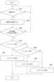
- FIG. 2 is a flowchart schematically showing the operation contents of the power management device for an electric vehicle according to the first embodiment.
- FIG. 2 is a block diagram schematically showing a power management device for an electric vehicle according to a second embodiment.
- 7 is a flowchart schematically showing the operation details of the power management device for an electric vehicle according to the second embodiment.
- FIG. 1 is a block diagram schematically showing a power management device 1A for an electric vehicle according to the first embodiment.
- a power management device 1A for an electric vehicle according to the first embodiment is employed in an electric vehicle such as an electric vehicle, a hybrid vehicle, or a plug-in hybrid vehicle.
- the plug-in hybrid vehicle can be externally charged and externally supplied with power, and is equipped with the electric vehicle power management device 1A according to the first embodiment.
- the electric vehicle includes a contactor 7 that electrically connects or disconnects the drive battery 3 and the auxiliary battery 5.
- a DC/DC converter 9 is provided between the contactor 7 and the auxiliary battery 5.
- the DCDC converter 9 is for converting the voltage of the driving battery 3 into a voltage that can be supplied to the auxiliary battery 5, and the driving battery 3 and the auxiliary battery 5 are electrically connected by the contactor 7. It is activated when the drive battery 3 and the auxiliary battery 5 are electrically cut off by the contactor 7, and is stopped when the contactor 7 electrically cuts off the drive battery 3 and the auxiliary battery 5.
- the electric vehicle power management device 1A includes a state management unit 11 and a connection management unit 13.
- the state management unit 11 and the connection management unit 13 each include a processor (not shown), a ROM (Read Only Memory), and a RAM (Random Access Memory (not shown), and an input interface (not shown).
- An auxiliary battery 5 is connected to the state management unit 11 and the connection management unit 13, and power is constantly supplied to the state management unit 11 and the connection management unit 13 from the auxiliary battery 5.
- the state management unit 11 is provided with a state determination section 15 that determines whether the ignition is on or auto ACC, and an information acquisition section 17 that acquires opening/closing information of the opening/closing member.
- Ignition on means that the ignition power is on; for example, pressing the power switch twice turns it on, and pressing it once again turns it off.
- Auto ACC is a state in which the accessory power is automatically turned on. For example, when the door is unlocked using the keyless operation key system, Auto ACC is turned on, and after the door is locked using the keyless operation key system, the auto ACC is turned on. It turns off when the specified time has elapsed.
- the opening/closing members are, for example, the front door, the engine hood 51, the tailgate 53, and the rear door 55, and in this embodiment, the engine hood 51, the tailgate 53, and the rear door 55 are particularly targeted.
- the tailgate 53 also includes a trunk lid.
- the connection management unit 13 is provided with a connection determination section 19 and a period determination section 21.
- the connection determination unit 19 is a part that determines whether or not the contactor 7 can be connected based on the determination result of the status determination unit 15 and the acquired information of the information acquisition unit 17, and the status determination unit 15 determines whether the ignition is on or auto ACC, In addition, when the information acquisition unit 17 acquires the closing information of the opening/closing member, it is determined that the connection is possible, and when the information acquisition unit 17 acquires the opening information of the opening/closing member, it is determined that the connection is not possible.
- the connection determination unit 19 determines that connection is not possible when the information acquisition unit 17 acquires the opening information of at least one of the engine hood 51, the tailgate 53, or the rear door 55, and acquires the opening information of the front door. Even if the connection is not possible.
- the reason why it is determined that the connection is not possible when the opening information of the engine hood 51 is obtained is that the opening of the engine hood 51 is considered to be a sign of access to a rotating body such as a cooling fan installed in the engine room.
- the reason why it is determined that connection is not possible when information on the opening of the tailgate 53 is obtained is because the opening of the tailgate 53 is considered to be a sign of access to the auxiliary battery 5 installed in the luggage compartment.
- the reason why it is determined that the connection is not possible when the opening information of the rear door 55 is obtained is that the opening of the rear door 55 is considered to be a sign of access to the drive battery 3 installed in the rear seat.
- connection determination unit 19 outputs a cutoff request to the contactor 7 when determining that connection is not possible. Thereby, the contactor 7 electrically disconnects the drive battery 3 and the auxiliary battery 5 when the connection determination unit 19 determines that the connection is not possible.
- the period determining unit 21 is a part that determines whether the period during which the connection determining unit 19 determines that connection is possible exceeds a predetermined period.
- the predetermined period is, for example, the time required for loading and unloading cargo, and can be set arbitrarily.
- the period determination unit 21 outputs a connection request to the contactor 7 when the connection determination unit 19 determines that the period in which connection is possible exceeds a predetermined period. Thereby, the contactor 7 electrically connects the driving battery 3 and the auxiliary battery 5 when the period determining unit 21 determines that the predetermined period has exceeded.
- FIG. 2 is a flowchart schematically showing the operation contents of the electric vehicle power management device 1A according to the first embodiment.
- the power management device 1A for an electric vehicle according to the first embodiment power is constantly supplied from the auxiliary battery 5 to the state management unit 11 and the connection management unit 13.
- the state management unit 11 the state determination section 15 monitors the ignition or auto ACC, and the information acquisition section 17 acquires the opening/closing information of the opening/closing member.
- a connection determination section 19 determines whether or not the contactor 7 can be connected.
- the connection determination section 19 determines whether or not the contactor 7 can be connected based on the determination result of the state determination section 15 and the acquired information of the information acquisition section 17. Specifically, as shown in FIG. 2, the determination result of the state determination unit 15 is that the ignition is on or the auto ACC is on (step S11: Yes), and the information acquired by the information acquisition unit 17 is all closed (step S13: Yes), the connection determination unit 19 determines that connection is possible. Then, when the period in which the connection determination section 19 determines that connection is possible exceeds a predetermined period, the period determination section 21 determines that the period has exceeded the predetermined period (step S15: Yes), and the period determination section 21 determines that the period has exceeded the predetermined period.
- a connection request is output to the contactor 7 (step S17).
- the contactor 7 electrically connects the drive battery 3 and the auxiliary battery 5.
- the DCDC converter 9 is activated, and the electric power charged in the drive battery 3 is converted into voltage by the DCDC converter 9 and supplied to the auxiliary battery 5.
- the auxiliary battery 5 is charged.
- step S11: Yes if the determination result of the state determination unit 15 is that the ignition is on or the auto ACC is on (step S11: Yes), if at least one of the acquired information of the information acquisition unit 17 is open (step S13: No), The connection determination unit 19 determines that connection is not possible. As a result, even if the connection determination unit 19 determines that the connection is possible (step S13: Yes), if the connection determination unit 19 determines that the connection is not possible before the predetermined period expires (step S13: No), the period determination The unit 21 never outputs a connection request to the contactor 7.
- connection request is output to the contactor 7 until the period during which the connection determination section 19 determines that connection is possible exceeds a predetermined period. There's nothing to do.
- connection determination unit 19 determines that the connection is not possible, and outputs a cutoff request to the contactor 7 (step S19).
- a cutoff request is input to the contactor 7, the contactor 7 electrically cuts off the drive battery 3 and the auxiliary battery 5. As a result, the DCDC converter 9 is stopped.
- the judgment result of the state judgment unit 15 is that the ignition is turned off and the auto ACC is turned off (step S21: No), and the connection judgment unit 19 judges that connection is not possible, and the connection judgment unit 19 outputs a cutoff request to the contactor 7 (step S19).
- the contactor 7 electrically cuts off the drive battery 3 and the auxiliary battery 5. As a result, the DCDC converter 9 is stopped.
- the contactor 7 connects the drive battery 3 and the auxiliary battery 5 until the period in which the connection determination unit 19 determines that connection is possible exceeds a predetermined period. Since the contactor 7 is not electrically connected to the contactor 7, the number of times the contactor 7 continuously repeats electrical connection and disconnection can be suppressed.
- the driving battery 3 and the auxiliary battery 5 are electrically cut off, so even if you accidentally access dangerous objects such as parts that carry high voltage current, you will not get an electric shock or the motor will rotate. It can reduce the risk of getting caught in the body. This makes electric vehicles safer.
- opening/closing member is the engine hood 51
- opening the engine hood 51 electrically cuts off the drive battery 3 and the auxiliary battery 5, so that the power supplied from the drive battery 3 to the engine room is Even if a rotating device such as a cooling fan operated by electric power is installed, the risk of being caught in the rotating body can be suppressed.
- opening/closing member is the tailgate 53
- opening the tailgate 53 electrically cuts off the drive battery 3 and the auxiliary battery 5, so the auxiliary battery 5 is located under the floor of the cargo compartment. Even if the auxiliary battery 5 is installed and accessible from the luggage compartment, the risk of electric shock due to the high voltage current supplied from the drive battery 3 to the auxiliary battery 5 can be suppressed.
- opening/closing member is the rear door 55
- opening the rear door 55 electrically cuts off the driving battery 3 and the auxiliary battery 5, so the driving battery 3 is installed under the rear seat, and the driving battery 3 is installed under the rear seat.
- the driving battery 3 is accessible from the outside, the risk of electric shock due to the high voltage current supplied from the driving battery 3 to external equipment can be suppressed.
- FIG. 3 is a block diagram schematically showing a power management device 1B for an electric vehicle according to the second embodiment.
- the configurations of the state management unit 11 of the power management device 1B for an electric vehicle according to the second embodiment and the connection determination unit 19 of the connection management unit 13 are the same as the state management unit 11 of the power management device 1B for an electric vehicle according to the first embodiment, and the connection determination section 19 of the connection management unit 13.
- connection management unit 13 is provided with a connection failure reason identification unit 23.
- the connection failure reason identifying unit 23 identifies the reason when the connection determination unit 19 determines that connection is not possible. For example, when the connection determination unit 19 determines that connection is not possible, the connection failure reason determination unit identifies the reason for connection failure based on the determination result of the status determination unit 15 and the acquired information of the information acquisition unit 17. do. For example, when the information obtained by the information acquisition unit 17 indicates that the opening/closing member is open, the connection failure reason specifying unit 23 identifies the reason for the connection failure as “opening/closing member opening”.
- connection failure reason determination unit also identifies the opening/closing member that is open when the information acquisition unit 17 acquires opening information for at least one of the engine hood 51, the tailgate 53, or the rear door 55. .
- opening/closing member that is open when the information acquisition unit 17 acquires opening information for at least one of the engine hood 51, the tailgate 53, or the rear door 55.
- connection failure reason identification unit 23 counts the number of times the connection determination unit 19 has made the connection failure, and when the number of times has exceeded a predetermined number, identifies the reason why the connection has been made impossible.
- the power management device 1B for an electric vehicle includes a display management unit 25 in addition to the state management unit 11 and the connection management unit 13.
- the display management unit 25 includes a processor (not shown) consisting of an arithmetic unit, a register for storing instructions and information, peripheral circuits, etc., and a memory (not shown) such as ROM (Read Only Memory) and RAM (Random Access Memory). (not shown) and an input interface (not shown).
- An auxiliary battery 5 is connected to the display management unit 25, and power is supplied from the auxiliary battery 5 to the display management unit 25.
- a display 27 is connected to the display management unit 25, and a connection failure reason display section 29 is provided.
- the display device 27 is, for example, a multi-information display 33 provided on the meter 31, and the connection failure reason display section 29 causes the display device 27 to display the reason for the connection failure specified by the connection failure reason specifying section 23.
- the reason for connection failure is "open engine hood 51”
- the display 27 Display.
- the reason for the connection failure is "the tailgate 53 is open”
- the message "The auxiliary battery has not been charged for a while. Please close the tailgate.” is displayed on the display 27.
- the reason for the inability to connect is "open rear door 55”
- the message "The auxiliary battery has not been charged for a while. Please close the rear seat door.” is displayed on the display 27.
- FIG. 4 is a flowchart schematically showing the operation contents of the electric vehicle power management device 1B according to the second embodiment.
- the operation of the state management unit 11 of the power management device 1B for an electric vehicle according to the second embodiment and the connection determination unit 19 of the connection management unit 13 is the same as that of the state management unit 11 of the power management device 1A for an electric vehicle according to the first embodiment. and the connection determination section 19 of the connection management unit 13.
- connection failure reason specifying unit 23 when the connection determining unit 19 determines that connection is not possible (Step S31; Yes), the connection failure reason specifying unit 23 counts the number of times (Step S33). If the number of times is equal to or greater than a predetermined number (step S35: Yes), the connection failure reason specifying unit 23 specifies the reason for the last connection failure (steps S37, S39). For example, when the connection failure reason specifying unit 23 identifies the reason for connection failure as the open engine hood (step S37: Yes), the connection failure reason display unit 29 displays a message A on the display 27 (“The auxiliary equipment battery will not be charged for a while. "Please close the bonnet.") is displayed (step S41).
- connection failure reason display unit 29 displays message B ( ⁇ The auxiliary battery has not been charged for a while. Please close the tailgate.'' (Step S43), and when the reason for the connection failure is specified as ⁇ Rear door 55 open'' (Step S39: No), the connection failure reason display section 29 displays the display 27. Message C ( ⁇ The auxiliary battery has not been charged for a while. Please close the rear seat door.'') is displayed on the screen (S45).
- the display 27 displays the opening information of the opening/closing member, so that the user does not have to look at the display 27. This shows that the reason for the electrical disconnection between the driving battery 3 and the auxiliary battery 5 is the opening of the opening/closing member.
Landscapes
- Engineering & Computer Science (AREA)
- Power Engineering (AREA)
- Transportation (AREA)
- Mechanical Engineering (AREA)
- Life Sciences & Earth Sciences (AREA)
- Sustainable Development (AREA)
- Sustainable Energy (AREA)
- Electric Propulsion And Braking For Vehicles (AREA)
Priority Applications (2)
| Application Number | Priority Date | Filing Date | Title |
|---|---|---|---|
| JP2024510913A JP7772199B2 (ja) | 2022-03-30 | 2022-03-30 | 電動車両の電源管理装置 |
| PCT/JP2022/016090 WO2023188139A1 (ja) | 2022-03-30 | 2022-03-30 | 電動車両の電源管理装置 |
Applications Claiming Priority (1)
| Application Number | Priority Date | Filing Date | Title |
|---|---|---|---|
| PCT/JP2022/016090 WO2023188139A1 (ja) | 2022-03-30 | 2022-03-30 | 電動車両の電源管理装置 |
Publications (1)
| Publication Number | Publication Date |
|---|---|
| WO2023188139A1 true WO2023188139A1 (ja) | 2023-10-05 |
Family
ID=88199753
Family Applications (1)
| Application Number | Title | Priority Date | Filing Date |
|---|---|---|---|
| PCT/JP2022/016090 Ceased WO2023188139A1 (ja) | 2022-03-30 | 2022-03-30 | 電動車両の電源管理装置 |
Country Status (2)
| Country | Link |
|---|---|
| JP (1) | JP7772199B2 (https=) |
| WO (1) | WO2023188139A1 (https=) |
Citations (7)
| Publication number | Priority date | Publication date | Assignee | Title |
|---|---|---|---|---|
| JPH0183232U (https=) * | 1987-11-25 | 1989-06-02 | ||
| JPH0765664A (ja) * | 1993-08-23 | 1995-03-10 | Sharp Corp | スイッチ制御回路 |
| JPH11176272A (ja) * | 1997-12-12 | 1999-07-02 | Toa Corp | スイッチの誤操作防止装置及びスイッチの誤操作防止装置を備えた音響信号処理装置 |
| JP2002087203A (ja) * | 2000-09-19 | 2002-03-27 | Honda Motor Co Ltd | 車両用フード装置 |
| JP2003082904A (ja) * | 2001-09-10 | 2003-03-19 | Mazda Motor Corp | 開閉体制御装置 |
| JP5247001B2 (ja) * | 2006-01-11 | 2013-07-24 | 富士通テン株式会社 | 車両の電源制御装置 |
| WO2021220340A1 (ja) * | 2020-04-27 | 2021-11-04 | 日産自動車株式会社 | 電源制御方法及び電源制御装置 |
-
2022
- 2022-03-30 WO PCT/JP2022/016090 patent/WO2023188139A1/ja not_active Ceased
- 2022-03-30 JP JP2024510913A patent/JP7772199B2/ja active Active
Patent Citations (7)
| Publication number | Priority date | Publication date | Assignee | Title |
|---|---|---|---|---|
| JPH0183232U (https=) * | 1987-11-25 | 1989-06-02 | ||
| JPH0765664A (ja) * | 1993-08-23 | 1995-03-10 | Sharp Corp | スイッチ制御回路 |
| JPH11176272A (ja) * | 1997-12-12 | 1999-07-02 | Toa Corp | スイッチの誤操作防止装置及びスイッチの誤操作防止装置を備えた音響信号処理装置 |
| JP2002087203A (ja) * | 2000-09-19 | 2002-03-27 | Honda Motor Co Ltd | 車両用フード装置 |
| JP2003082904A (ja) * | 2001-09-10 | 2003-03-19 | Mazda Motor Corp | 開閉体制御装置 |
| JP5247001B2 (ja) * | 2006-01-11 | 2013-07-24 | 富士通テン株式会社 | 車両の電源制御装置 |
| WO2021220340A1 (ja) * | 2020-04-27 | 2021-11-04 | 日産自動車株式会社 | 電源制御方法及び電源制御装置 |
Also Published As
| Publication number | Publication date |
|---|---|
| JP7772199B2 (ja) | 2025-11-18 |
| JPWO2023188139A1 (https=) | 2023-10-05 |
Similar Documents
| Publication | Publication Date | Title |
|---|---|---|
| US10639998B2 (en) | Service disconnect notification strategy | |
| JP3450220B2 (ja) | 車両用電源装置 | |
| US20130030621A1 (en) | Discharge technique for residual high voltage in hybrid vehicle and method thereof | |
| US20150188345A1 (en) | Vehicle door | |
| CN110494320B (zh) | 车辆用电源系统 | |
| JP2013035466A (ja) | 車両駆動用モータを有する自動車 | |
| CN113895383A (zh) | 车辆控制设备、控制方法、非暂时性存储介质和车辆 | |
| EP3620331A1 (en) | Vehicle surroundings display device | |
| CN113954690A (zh) | 用于机动车辆的电池放电控制系统及方法 | |
| US20250178457A1 (en) | Electric work vehicle | |
| JP6546949B2 (ja) | 車両 | |
| CN114585791A (zh) | 用于锁定和/或解锁可移动的汽车闭合机构的闭锁装置 | |
| WO2023188139A1 (ja) | 電動車両の電源管理装置 | |
| WO2023188133A1 (ja) | 電動車両の電源管理装置 | |
| CN109693567A (zh) | 用于控制充电插口的锁定的方法及系统 | |
| CN107461106A (zh) | 根据变速器状态关闭机动车辆的闭合装置的自动化系统 | |
| JP2005255085A (ja) | 車両用空調装置 | |
| JP2017216830A (ja) | 車両用電源装置 | |
| CN115303211A (zh) | 用于保护卡车的车载电气网络的方法 | |
| CN112793523A (zh) | 包括连接到电池的远程端子以防止电子篡改的车辆 | |
| JP2019094718A (ja) | 車両用電動ドアの制御装置 | |
| US12459390B2 (en) | Method and a master control unit for controlling an electrical system of an electric vehicle | |
| JP2020156269A (ja) | 架装物駆動制御システム | |
| CN117597247A (zh) | 包括电池的机动车辆 | |
| JPH10284136A (ja) | 電気自動車用電池温度調整装置 |
Legal Events
| Date | Code | Title | Description |
|---|---|---|---|
| 121 | Ep: the epo has been informed by wipo that ep was designated in this application |
Ref document number: 22935284 Country of ref document: EP Kind code of ref document: A1 |
|
| DPE1 | Request for preliminary examination filed after expiration of 19th month from priority date (pct application filed from 20040101) | ||
| ENP | Entry into the national phase |
Ref document number: 2024510913 Country of ref document: JP Kind code of ref document: A |
|
| NENP | Non-entry into the national phase |
Ref country code: DE |
|
| 122 | Ep: pct application non-entry in european phase |
Ref document number: 22935284 Country of ref document: EP Kind code of ref document: A1 |