WO2023188067A1 - エレベータの脱レール検出システム - Google Patents
エレベータの脱レール検出システム Download PDFInfo
- Publication number
- WO2023188067A1 WO2023188067A1 PCT/JP2022/015832 JP2022015832W WO2023188067A1 WO 2023188067 A1 WO2023188067 A1 WO 2023188067A1 JP 2022015832 W JP2022015832 W JP 2022015832W WO 2023188067 A1 WO2023188067 A1 WO 2023188067A1
- Authority
- WO
- WIPO (PCT)
- Prior art keywords
- distance
- counterweight
- rail
- elevator
- hoistway
- Prior art date
Links
- 238000001514 detection method Methods 0.000 title claims abstract description 45
- 238000010586 diagram Methods 0.000 description 11
- 230000000694 effects Effects 0.000 description 2
- 238000000034 method Methods 0.000 description 2
- 230000003028 elevating effect Effects 0.000 description 1
- 230000006870 function Effects 0.000 description 1
- 238000009434 installation Methods 0.000 description 1
- 230000002452 interceptive effect Effects 0.000 description 1
- 230000003068 static effect Effects 0.000 description 1
Images


Classifications
-
- B—PERFORMING OPERATIONS; TRANSPORTING
- B66—HOISTING; LIFTING; HAULING
- B66B—ELEVATORS; ESCALATORS OR MOVING WALKWAYS
- B66B5/00—Applications of checking, fault-correcting, or safety devices in elevators
- B66B5/02—Applications of checking, fault-correcting, or safety devices in elevators responsive to abnormal operating conditions
Definitions
- the present disclosure relates to an elevator off-rail detection system that detects when an elevator counterweight has come off the rail due to an earthquake or the like.
- a conventional elevator off-rail detection system uses a photoelectric sensor to measure the distance to a detected object at the lower end of a wire suspended parallel to the counterweight rail.
- the method of detecting off-rails using a photoelectric sensor detects that when the counterweight comes off and the wire is pulled, the distance to the object to be detected connected to the lower end of the wire changes (for example, Patent Document 1).
- the present disclosure has been made in order to solve the above-mentioned problems, and there is a possibility of interference with lifting objects such as cars and counterweights moving in the hoistway, and there is a possibility of interference with lifting objects such as cars and counterweights that move in the hoistway, and parallel to the rail of the counterweight.
- An elevator off-rail detection system includes a counterweight that moves up and down along a rail installed in an elevator hoistway, and a counterweight that is installed on the counterweight and that is connected between a wall surface of the hoistway and the counterweight.
- the distance measuring means detects at least one of the distance and the distance between the rail and the counterweight, and the distance determining means outputs a distance detection signal based on the distance transmitted from the distance measuring means.
- the distance determining means outputs ON as a distance detection signal when the distance is a first distance or more and less than a second distance larger than the first distance, and when the distance is less than the first distance or more than a second distance, It is characterized by outputting OFF as a distance detection signal.
- FIG. 1 is an overall configuration diagram of a general elevator.
- FIG. 3 is a view of a counterweight viewed from the upper side of the hoisting path of the elevator in Embodiment 1.
- 1 is a block diagram of an elevator derailment detection system in Embodiment 1.
- FIG. 2 is a flowchart of the elevator derailment detection system in the first embodiment.
- FIG. 3 is a configuration diagram in which the height of the counterweight from the bottom of the hoistway and the wall distance in the first embodiment are stored.
- FIG. 1 is an overall configuration diagram of a general elevator.
- the elevator includes a car 1, a main rope 2, a counterweight 3, a hoist 4, a rotation detector 5, a control panel 7, and a communication cable 8.
- a main rope 2 is connected to the upper end of the car 1, and a counterweight 3 is connected to the other end of the main rope 2.
- the hoist 4 is installed in the middle of the main rope 2 so that the car 1 and the counterweight 3 move up and down in opposite directions.
- the counterweight 3 moves along the hoistway wall 12 of the hoistway.
- the hoistway wall 12 is defined as a wall surface of the hoistway.
- the control panel 7 drives the hoisting machine 4 to control the raising and lowering of the car 1, and also controls the movement of the car 1 and the counterweight 3 based on a signal from a rotation detector 5 attached to the rotating shaft of the hoisting machine 4. Calculate the position (height) from the bottom of the hoistway in the hoistway.
- the control panel 7 receives signals from devices installed on the counterweight 3 via a communication cable 8.
- FIG. 2 is a view of the counterweight viewed from the upper side of the hoistway of the elevator according to the first embodiment.
- the counterweight 3 moves up and down in the hoistway along the rails 13, 13a. Further, the counterweight 3 includes distance measuring means 21 and 21a.
- the distance measuring means 21 measures the left wall surface distance (D1 in FIG. 2), which is the distance to the hoistway wall 12, and the left rail distance (L1 in FIG. 2), which is the distance to the rail 13, and connects the communication cable 8. The left wall distance and left rail distance are sent to the control panel 7 via.
- the distance measuring means 21a measures the right wall surface distance (D2 in FIG. 2), which is the distance to the hoistway wall 12, and the right rail distance (L2 in FIG. 2), which is the distance to the rail 13a. The right wall distance and the right rail distance are transmitted to the control panel 7 via the communication cable 8.
- a distance measuring means 21, 21a a distance meter, such as a laser distance meter or an ultrasonic distance meter, is used, which utilizes the time it takes for light, sound, etc. to reflect from an object and return.
- the distance measuring means 21 and 21a are shown installed at the top of the counterweight 3, they may be installed at the bottom of the counterweight 3, or at two locations on the top and two locations on the bottom of the counterweight 3. They may be installed at different locations.
- FIG. 3 is a block diagram of the elevator derailment detection system according to the first embodiment.
- the control panel 7 of the elevator derailment detection system includes an I/F means 31, a CPU 32, a storage means 33, and an elevation control means 34.
- the I/F means 31 of the control panel 7 receives the left wall distance, right wall distance, left rail distance, and right rail distance transmitted from the distance measuring means 21 and 21a installed on the counterweight 3, and The received distance information of each distance is transmitted to the CPU 32.
- the CPU 32 receives a rotation detection signal from the rotation detector 5 attached to the hoisting machine 4 via the lift control means 34, and determines the height of the counterweight 3 from the floor of the hoistway. calculate.
- the CPU 32 receives the distance information from the distance measuring means 21, 21a and the rotation detection signal from the rotation detector 5 via the elevation control means 34, and detects when the counterweight 3 comes off the rails 13, 13a. Determine whether or not.
- the CPU 32 has a function of distance determining means.
- the storage means 33 stores the control program for the CPU section 32, the data of control calculations, and the values that associate the height of the counterweight with the determination value of the distance information.
- the storage means 32 may be any means that can store data and read the stored data, such as SRAM (Static Random Access Memory) or EEPROM (Electrically Erasable Programmable Read Only Memory). .
- the lift control means 34 receives a signal transmitted from the CPU 32 and operates and stops the car 1.
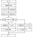
- FIG. 4 is a flowchart of the elevator derailment detection system according to the first embodiment.
- FIG. 5 is a configuration diagram in which the height of the counterweight of the rail derailment detection system and the first distance and second distance between the wall and the rail are stored.
- step S1 the CPU 32 of the elevator control panel 7 receives the left wall distance, right wall distance, left rail distance, and right rail distance transmitted from the distance measuring means 21 and 21a.
- step S2 the CPU 32 receives a rotation detection signal from the rotation detector 5 attached to the hoisting machine 4 via the lift control means 34, and adjusts the balance of the counterweight 3 from the floor in the hoistway. Calculate the weight height.
- step S3 the CPU 32 controls the first and second left wall distances, the first and second right wall distances, and the first and second left rail distances associated with the height of the counterweight 3.
- the first distance, the second distance, and the first distance and the second distance of the right rail distance are read from the storage means 33.
- FIG. 5 a configuration diagram in which the height of the counterweight 3 of the rail derailment detection system, distance information to the hoistway wall 12, and distance information to the rail are stored will be described using FIG.
- the first distance and the second distance of the left wall surface distance are stored in the storage means 33 as 240 mm and 260 mm, respectively.
- the first distance and the second distance of the right wall surface distance are stored in the storage means 33 as 490 mm and 510 mm, respectively.
- the first distance and the second distance of the left rail distance are stored in the storage means 33 as 90 mm and 110 mm, respectively.
- the first distance and the second distance of the right rail distance are stored in the storage means 33 as 100 mm and 120 mm, respectively.
- the difference between the left wall surface distance and the right wall surface distance depends on the case where the shaft wall 12 of the shaft has irregularities or a building beam protrudes.
- the difference between the left rail distance and the right rail distance is due to the unevenness of the rail clip used when fixing the device to the rail 13 via the mounting arm.
- the counterweight height may be set in 100 mm steps over the entire length of the hoistway.
- the left wall distance, right wall distance, left rail distance, and right rail distance with respect to the height of the counterweight are set in advance using information on the structure of the building where elevator car 1 is installed, the hoistway, etc.
- the left wall distance, right wall distance, left rail distance, and right rail distance with respect to the height of the counterweight may be determined.
- the first distance and the second distance may be stored in the storage means 33.
- step S4 the CPU 32 determines whether the left wall distance, right wall distance, left rail distance, and right rail distance are all greater than or equal to the first distance and less than a second distance that is greater than the first distance. If the left wall distance, right wall distance, left rail distance, and right rail distance are all greater than or equal to the first distance and less than the second distance, which is greater than the first distance, the CPU 32 moves to step S5 (step S4 YES). On the other hand, if at least one of the left wall distance, right wall distance, left rail distance, and right rail distance is less than the first distance or greater than or equal to the second distance, the process moves to step S7 (NO in step S4). ).
- step S5 the CPU 32 outputs the distance detection signal as ON.
- step S6 the lift control means 34 receives the ON distance detection signal transmitted from the CPU 32, and causes the car 1 to continue operating.
- step S7 the CPU 32 outputs that the distance detection signal is OFF.
- step S8 the lift control means 34 receives the OFF of the distance detection signal transmitted from the CPU 32, and stops the operation of the car 1.
- the first and second left wall distances, the first and second right wall distances, and the first left rail distance are related to the height of the counterweight.
- the distance and the second distance, and the first and second distances of the right rail distance are read out from the storage means 33, if there is no change in the distance to the hoistway wall 12 or the rail, the first distance and the second distance are read out from the storage means 33.
- the distance may be a constant value regardless of the height of the counterweight.
- the balance weight 3 has been described as having two distance measuring means 21 and 21a, one distance measuring means 21 may be provided.
- the distance measuring means 21 has been described as measuring the wall distance to the hoistway wall 12 and the rail distance to the rail 13, it may measure at least one of the wall distance and the rail distance. Installing a plurality of distance measuring means 21 improves the reliability of rail deviation detection.
- the elevator off-rail detection system of the present disclosure configured as described above includes a counterweight 3 that moves up and down along the rails 13 and 13a installed in the hoistway of the elevator, and a counterweight 3 that is installed in the counterweight 3 and that moves up and down.
- the distance measuring means 21 detects at least one of the distance between the road wall surface and the counterweight 3, and the distance between the rails 13, 13a and the counterweight 3; distance determination means for outputting a distance detection signal based on the distance determined, the distance determination means turning ON as the distance detection signal when the distance is greater than or equal to the first distance and less than a second distance greater than the first distance. When the distance is less than the first distance or greater than or equal to the second distance, OFF is output as the distance detection signal.
- the elevator derailment detection system also includes a lift control means 34 in which the car 1 and the counterweight 3 are connected by the main rope 2, and controls the car 1 and the counterweight 3 to move up and down in opposite directions.
- the elevator control means 34 is characterized in that it stops the car 1 and the counterweight 3 when receiving the OFF state of the distance detection signal.
Landscapes
- Maintenance And Inspection Apparatuses For Elevators (AREA)
Abstract
本開示は、地震等によりエレベータの釣合おもりがレールから外れたことを検出するエレベータの脱レール検出システムに関するものである。 従来のエレベータの脱レール検出システムには、昇降路内を移動するかご、釣合おもりなどの昇降体と移動空間が干渉しないようにし、かつ釣合おもりのレールと平行に吊り下げられるワイヤ線が必要となるといった課題がある。 エレベータの脱レール検出システムは、昇降路内を移動するかご、釣合おもりなどの昇降体との干渉の可能性が有り、釣合おもりのレールと平行に吊り下げが必要となるワイヤ線を使用すること無しに、脱レールの検出が可能なエレベータの脱レール検出システムを提供することを目的とする。
Description
本開示は、地震等によりエレベータの釣合おもりがレールから外れたことを検出するエレベータの脱レール検出システムに関するものである。
従来のエレベータの脱レール検出システムは光電センサを利用し、釣合おもりのレールと平行に吊り下げられるワイヤの下端にある被検出体との距離を測定する。その光電センサによる脱レール検出の方法は、釣合おもりが外れてワイヤが引っ張られたときに、ワイヤの下端に接続された被検出体との距離が変化したことを検出する(例えば、特許文献1)。
従来のエレベータの脱レール検出システムには、昇降路内を移動するかご、釣合おもりなどの昇降体と移動空間が干渉しないようにし、かつ釣合おもりのレールと平行に吊り下げられるワイヤ線が必要となるといった課題がある。
本開示は、上記した問題点を解決するためになされたものであり、昇降路内を移動するかご、釣合おもりなどの昇降体との干渉の可能性が有り、釣合おもりのレールと平行に吊り下げが必要となるワイヤ線を使用すること無しに、脱レールの検出が可能なエレベータの脱レール検出システムを提供することを目的とする。
本開示に係るエレベータの脱レール検出システムは、エレベータの昇降路に設置されたレールに沿って昇降する釣合おもりと、釣合おもりに設置され、昇降路の壁面と釣合おもりとの間の距離と、レールと釣合おもりとの間の距離と、の少なくとも一方を検出する距離計測手段と、距離計測手段から送信された距離に基いて距離検知信号を出力する距離判定手段と、を備え、距離判定手段は、距離が第1距離以上、かつ第1距離より大きい第2距離未満の場合に距離検知信号としてONを出力し、距離が第1距離未満または第2距離以上の場合に、距離検知信号としてOFFを出力することを特徴とする。
本開示によれば、昇降路内を移動するかご、釣合おもりなどの昇降体との干渉の可能性が有り、釣合おもりのレールと平行に吊り下げが必要となるワイヤ線を使用すること無しに、脱レールの検出が可能になるという効果を奏する。
実施の形態1.
図1を用いて一般的なエレベータの全体構成図を説明する。図1は、一般的なエレベータの全体構成図である。
図1を用いて一般的なエレベータの全体構成図を説明する。図1は、一般的なエレベータの全体構成図である。
エレベータは、かご1、主ロープ2、釣合おもり3、巻上機4、回転検出器5、制御盤7、及び通信ケーブル8を備える。
かご1の上端には、主ロープ2の一端が接続され、主ロープ2の他端には、釣合おもり3が接続されている。巻上機4は、かご1と釣合おもり3が互いに相反する方向に昇降するよう主ロープ2の中間部に設置されている。
釣合おもり3は、昇降路の昇降路壁12に沿って移動する。
昇降路壁12は、昇降路の壁面と定義する。
かご1の上端には、主ロープ2の一端が接続され、主ロープ2の他端には、釣合おもり3が接続されている。巻上機4は、かご1と釣合おもり3が互いに相反する方向に昇降するよう主ロープ2の中間部に設置されている。
釣合おもり3は、昇降路の昇降路壁12に沿って移動する。
昇降路壁12は、昇降路の壁面と定義する。
制御盤7は、巻上機4を駆動し、かご1の昇降制御を行うとともに、巻上機4の回転軸に取り付けられた回転検出器5からの信号により、かご1と釣合おもり3との昇降路内での昇降路底面からの位置(高さ)を算出する。
制御盤7は、通信ケーブル8により釣合おもり3に設置された機器からの信号を受信する。
制御盤7は、通信ケーブル8により釣合おもり3に設置された機器からの信号を受信する。
図2を用いて実施の形態1に係る釣合おもり3に設置された機器を、エレベータの昇降路上部側から釣合おもりを見た図で説明する。
図2は、実施の形態1に係るエレベータの昇降路上部側から釣合おもりを見た図である。
図2は、実施の形態1に係るエレベータの昇降路上部側から釣合おもりを見た図である。
釣合おもり3は、レール13、13aに沿って昇降路内を昇降する。また、釣合おもり3は、距離計測手段21、21aを備える。
距離計測手段21は、昇降路壁12までの距離である左壁面距離(図2のD1)や、レール13までの距離である左レール距離(図2のL1)をそれぞれ計測し、通信ケーブル8を経由して制御盤7に左壁面距離と左レール距離とを送信する。
同様に、距離計測手段21aは、昇降路壁12までの距離である右壁面距離(図2のD2)や、レール13aまでの距離である右レール距離(図2のL2)をそれぞれ計測し、通信ケーブル8を経由して制御盤7に右壁面距離と右レール距離とを送信する。
距離計測手段21は、昇降路壁12までの距離である左壁面距離(図2のD1)や、レール13までの距離である左レール距離(図2のL1)をそれぞれ計測し、通信ケーブル8を経由して制御盤7に左壁面距離と左レール距離とを送信する。
同様に、距離計測手段21aは、昇降路壁12までの距離である右壁面距離(図2のD2)や、レール13aまでの距離である右レール距離(図2のL2)をそれぞれ計測し、通信ケーブル8を経由して制御盤7に右壁面距離と右レール距離とを送信する。
例えば、距離計測手段21、21aとしては、レーザ距離計や超音波距離計のような、光や音などが物体に反射して帰ってくるまでの時間を利用した距離計を利用する。
距離計測手段21、21aは、釣合おもり3の上部に設置された状態を図示したが、釣合おもり3の下部に設置されてもよし、釣合おもり3の上部の2箇所と下部の2箇所に、それぞれ設置してもよい。
距離計測手段21、21aは、釣合おもり3の上部に設置された状態を図示したが、釣合おもり3の下部に設置されてもよし、釣合おもり3の上部の2箇所と下部の2箇所に、それぞれ設置してもよい。
図3を用いて実施の形態1に係るエレベータの脱レール検出システムのブロック図を説明する。図3は、実施の形態1に係るエレベータの脱レール検出システムのブロック図である。
エレベータの脱レール検出システムの制御盤7は、I/F手段31、CPU32、記憶手段33、及び昇降制御手段34を備える。
制御盤7のI/F手段31は、釣合おもり3に設置された距離計測手段21、21aから送信される左壁面距離、右壁面距離、左レール距離、及び右レール距離を受信して、その受信したそれぞれの距離の距離情報をCPU32に送信する。
制御盤7のI/F手段31は、釣合おもり3に設置された距離計測手段21、21aから送信される左壁面距離、右壁面距離、左レール距離、及び右レール距離を受信して、その受信したそれぞれの距離の距離情報をCPU32に送信する。
CPU32は、昇降制御手段34を経由して巻上機4に取付けられた回転検出器5からの回転検出信号を受信し、昇降路の床面からの釣合おもり3の釣合おもり高さを算出する。
CPU32は、距離計測手段21、21aからの距離情報の受信と、昇降制御手段34を経由して回転検出器5からの回転検出信号とを受信し、釣合おもり3がレール13,13aから外れたか否かを判定する。
CPU32は、距離判定手段の機能を備える。
CPU32は、距離計測手段21、21aからの距離情報の受信と、昇降制御手段34を経由して回転検出器5からの回転検出信号とを受信し、釣合おもり3がレール13,13aから外れたか否かを判定する。
CPU32は、距離判定手段の機能を備える。
記憶手段33は、CPU部32の制御プログラムの格納、制御演算のデータの保存、釣合おもり高さと距離情報の判定値とを関連づけした値などの保存を行う。
記憶手段32は、SRAM(Static Random access Memory)、EEPROM(Electrically Erasable Programmable Read Only Memorey)などを使用し、データを記憶し、その記憶したデータを読み出せる手段であれば何でもよい。
昇降制御手段34は、CPU32から送信された信号を受信し、かご1の運転と停止とを行う。
記憶手段32は、SRAM(Static Random access Memory)、EEPROM(Electrically Erasable Programmable Read Only Memorey)などを使用し、データを記憶し、その記憶したデータを読み出せる手段であれば何でもよい。
昇降制御手段34は、CPU32から送信された信号を受信し、かご1の運転と停止とを行う。
図4と図5とを用いて実施の形態1に係るエレベータの脱レール検出システムのフローチャートを説明する。図4は、実施の形態1に係るエレベータの脱レール検出システムのフローチャートである。
図5は、脱レール検出システムの釣合おもり高さと、壁面及びレールとのそれぞれの第1距離と第2距離とを記憶した構成図である。
図5は、脱レール検出システムの釣合おもり高さと、壁面及びレールとのそれぞれの第1距離と第2距離とを記憶した構成図である。
ステップS1において、エレベータの制御盤7のCPU32は、距離計測手段21、21aから送信される左壁面距離、右壁面距離、左レール距離、及び右レール距離を受信する。
ステップS2において、CPU32は、昇降制御手段34を経由して巻上機4に取付けられた回転検出器5からの回転検出信号を受信し、昇降路内の床面から釣合おもり3の釣合おもり高さを算出する。
ステップS2において、CPU32は、昇降制御手段34を経由して巻上機4に取付けられた回転検出器5からの回転検出信号を受信し、昇降路内の床面から釣合おもり3の釣合おもり高さを算出する。
ステップS3において、CPU32は、釣合おもり3の釣合おもり高さに関連付けられた左壁面距離の第1距離と第2距離、右壁面距離の第1距離と第2距離、左レール距離の第1距離と第2距離、及び右レール距離の第1距離と第2距離を記憶手段33から読み出す。
ここで、図5を用いて脱レール検出システムの釣合おもり3の釣合おもり高さと、昇降路壁12までの距離情報及びレールまでの距離情報とを記憶した構成図について説明する。
図5の構成図では、釣合おもり3の釣合おもり高さが5.3mの時に、左壁面距離の第1距離と第2距離とは、それぞれ240mm、260mmが記憶手段33に記憶されている。
同様に、右壁面距離の第1距離と第2距離とは、それぞれ490mm、510mmが記憶手段33に記憶されている。
左レール距離の第1距離と第2距離とは、それぞれ90mm、110mmが記憶手段33に記憶されている。
右レール距離の第1距離と第2距離とは、それぞれ100mm、120mmが記憶手段33に記憶されている。
図5の構成図では、釣合おもり3の釣合おもり高さが5.3mの時に、左壁面距離の第1距離と第2距離とは、それぞれ240mm、260mmが記憶手段33に記憶されている。
同様に、右壁面距離の第1距離と第2距離とは、それぞれ490mm、510mmが記憶手段33に記憶されている。
左レール距離の第1距離と第2距離とは、それぞれ90mm、110mmが記憶手段33に記憶されている。
右レール距離の第1距離と第2距離とは、それぞれ100mm、120mmが記憶手段33に記憶されている。
この左壁面距離と右壁面距離との違いは、昇降路の昇降路壁12に凹凸があったり、建物梁が突出していたりする場合による。
左レール距離と右レール距離との違いは、レール13に取付腕を介して機器を固定する際に使用するレールクリップの凹凸による。
左レール距離と右レール距離との違いは、レール13に取付腕を介して機器を固定する際に使用するレールクリップの凹凸による。
図5の構成図では、釣合おもり高さが4種類であるが、細かく設定してもよい。
例えば、釣合おもり高さは100mmステップごとに、昇降路の全行程にわたって設定してもよい。また、釣合おもり高さに対する左壁面距離、右壁面距離、左レール距離、及び右レール距離は、あらかじめエレベータのかご1が設置される建物や昇降路などの構造の情報を利用して設定してもよいし、エレベータを据付完了した後に、釣合おもり3を最下位置から最上位置まで昇降させながら、釣合おもり高さに対する左壁面距離、右壁面距離、左レール距離、及び右レール距離における第1距離と第2距離とを記憶手段33に記憶させてもよい。
例えば、釣合おもり高さは100mmステップごとに、昇降路の全行程にわたって設定してもよい。また、釣合おもり高さに対する左壁面距離、右壁面距離、左レール距離、及び右レール距離は、あらかじめエレベータのかご1が設置される建物や昇降路などの構造の情報を利用して設定してもよいし、エレベータを据付完了した後に、釣合おもり3を最下位置から最上位置まで昇降させながら、釣合おもり高さに対する左壁面距離、右壁面距離、左レール距離、及び右レール距離における第1距離と第2距離とを記憶手段33に記憶させてもよい。
ステップS4において、CPU32は、左壁面距離、右壁面距離、左レール距離、及び右レール距離の距離が全て第1距離以上、かつ第1距離より大きい第2距離未満か否かを判定する。
CPU32は、左壁面距離、右壁面距離、左レール距離、及び右レール距離の距離が全て第1距離以上、かつ第1距離より大きい第2距離未満の場合は、ステップS5に移行する(ステップS4のYES)。一方、左壁面距離、右壁面距離、左レール距離、及び右レール距離の内、少なくともひとつの距離が第1距離未満、または第2距離以上の場合は、ステップS7に移行する(ステップS4のNO)。
CPU32は、左壁面距離、右壁面距離、左レール距離、及び右レール距離の距離が全て第1距離以上、かつ第1距離より大きい第2距離未満の場合は、ステップS5に移行する(ステップS4のYES)。一方、左壁面距離、右壁面距離、左レール距離、及び右レール距離の内、少なくともひとつの距離が第1距離未満、または第2距離以上の場合は、ステップS7に移行する(ステップS4のNO)。
ステップS5において、CPU32は、距離検知信号がONを出力する。
ステップS6において、昇降制御手段34は、CPU32から送信された距離検知信号のONを受信し、かご1の運転を継続させる。
ステップS6において、昇降制御手段34は、CPU32から送信された距離検知信号のONを受信し、かご1の運転を継続させる。
ステップS7において、CPU32は、距離検知信号がOFFを出力する。
ステップS8において、昇降制御手段34は、CPU32から送信された距離検知信号のOFFを受信し、かご1の運転を停止させる。
ステップS8において、昇降制御手段34は、CPU32から送信された距離検知信号のOFFを受信し、かご1の運転を停止させる。
図4と図5のフローチャートの説明において、釣合おもり高さに関連付けられた左壁面距離の第1距離と第2距離、右壁面距離の第1距離と第2距離、左レール距離の第1距離と第2距離、及び右レール距離の第1距離と第2距離を記憶手段33から読み出すとしたが、昇降路壁12やレールとの距離に変化がない場合は、第1距離と第2距離は、釣合おもり高さに関係なく一定値としてもよい。
また、距離計測手段21、21aは、釣合おもり3に2個を備える内容で説明したが、距離計測手段21が1個でもよい。
距離計測手段21は、昇降路壁12までの壁面距離とレール13とのレール距離とをそれぞれ計測する内容で説明したが、壁面距離とレール距離との少なくとも一方であってもよい。
距離計測手段21を複数設置することは、脱レール検出の信頼性が向上する。
距離計測手段21は、昇降路壁12までの壁面距離とレール13とのレール距離とをそれぞれ計測する内容で説明したが、壁面距離とレール距離との少なくとも一方であってもよい。
距離計測手段21を複数設置することは、脱レール検出の信頼性が向上する。
以上のように構成された本開示のエレベータの脱レール検出システムは、エレベータの昇降路に設置されたレール13,13aに沿って昇降する釣合おもり3と、釣合おもり3に設置され、昇降路の壁面と釣合おもり3との間の距離と、レール13,13aと釣合おもり3との間の距離と、の少なくとも一方を検出する距離計測手段21と、距離計測手段21から送信された距離に基いて距離検知信号を出力する距離判定手段と、を備え、距離判定手段は、距離が第1距離以上、かつ第1距離より大きい第2距離未満の場合に距離検知信号としてONを出力し、距離が第1距離未満または第2距離以上の場合に、距離検知信号としてOFFを出力することを特徴とする。
これにより、昇降路内を移動するかご、釣合おもりなどの昇降体との干渉の可能性が有り、釣合おもりのレールと平行に吊り下げが必要となるワイヤ線を使用すること無しに、脱レールの検出が可能になるという効果を奏する。
さらに、昇降路壁12が平面ではなく、凹凸があったり、建物梁が突出していたりする場合でも、脱レールの検出が可能なエレベータの脱レール検出システムを提供できるという効果を奏する。
さらに、昇降路壁12が平面ではなく、凹凸があったり、建物梁が突出していたりする場合でも、脱レールの検出が可能なエレベータの脱レール検出システムを提供できるという効果を奏する。
また、エレベータの脱レール検出システムは、かご1と釣合おもり3とが主ロープ2によって接続され、かご1と釣合おもり3とを相反する方向に昇降させる制御を行う昇降制御手段34を備え、昇降制御手段34は、距離検知信号のOFFを受信したときに、かご1と釣合おもり3とを停止させることを特徴とする。
これにより、釣合おもりが何らかの理由によりレールから外れた場合に、エレベータの脱レール検出システムからの距離検知信号に基いて、すぐにかごと釣合おもりとを停止させるこが可能となるという効果を奏する。
1 かご1、 2 主ロープ、 3 釣合おもり、 4 巻上機、 5 回転検出器、 7 制御盤、 8 通信ケーブル、 11 乗場の戸、 12、12a 昇降路壁、 13、13a レール、 21、21a 距離計測手段、 31 I/F手段、 32 CPU、 33 記憶手段、 34 昇降制御手段
Claims (2)
- エレベータの昇降路に設置されたレールに沿って昇降する釣合おもりと、前記釣合おもりに設置され、前記昇降路の壁面と前記釣合おもりとの間の距離と、前記レールと前記釣合おもりとの間の距離と、の少なくとも一方を検出する距離計測手段と、前記距離計測手段から送信された前記距離に基いて距離検知信号を出力する距離判定手段と、を備え、
前記距離判定手段は、前記距離が第1距離以上、かつ前記第1距離より大きい第2距離未満の場合に前記距離検知信号としてONを出力し、前記距離が前記第1距離未満または前記第2距離以上の場合に、前記距離検知信号としてOFFを出力することを特徴とするエレベータの脱レール検出システム。 - かごと前記釣合おもりとが主ロープによって接続され、前記かごと前記釣合おもりとを相反する方向に昇降させる制御を行う昇降制御手段を備え、
前記昇降制御手段は、前記距離検知信号のOFFを受信したときに、前記かごと前記釣合おもりとを停止させることを特徴とする請求項1に記載のエレベータの脱レール検出システム。
Priority Applications (1)
| Application Number | Priority Date | Filing Date | Title |
|---|---|---|---|
| PCT/JP2022/015832 WO2023188067A1 (ja) | 2022-03-30 | 2022-03-30 | エレベータの脱レール検出システム |
Applications Claiming Priority (1)
| Application Number | Priority Date | Filing Date | Title |
|---|---|---|---|
| PCT/JP2022/015832 WO2023188067A1 (ja) | 2022-03-30 | 2022-03-30 | エレベータの脱レール検出システム |
Publications (1)
| Publication Number | Publication Date |
|---|---|
| WO2023188067A1 true WO2023188067A1 (ja) | 2023-10-05 |
Family
ID=88200284
Family Applications (1)
| Application Number | Title | Priority Date | Filing Date |
|---|---|---|---|
| PCT/JP2022/015832 WO2023188067A1 (ja) | 2022-03-30 | 2022-03-30 | エレベータの脱レール検出システム |
Country Status (1)
| Country | Link |
|---|---|
| WO (1) | WO2023188067A1 (ja) |
Citations (5)
| Publication number | Priority date | Publication date | Assignee | Title |
|---|---|---|---|---|
| JPS62168418U (ja) * | 1986-04-16 | 1987-10-26 | ||
| US20130206515A1 (en) * | 2012-02-14 | 2013-08-15 | Daniel Quinn | Movable body derailment detection system |
| WO2017183084A1 (ja) * | 2016-04-18 | 2017-10-26 | 三菱電機株式会社 | エレベータの脱レール検出装置 |
| WO2018198243A1 (ja) * | 2017-04-26 | 2018-11-01 | 三菱電機株式会社 | エレベータの釣合おもりの脱レール検出装置 |
| JP2022036525A (ja) * | 2020-08-24 | 2022-03-08 | 東芝エレベータ株式会社 | エレベータの脱レール検出装置 |
-
2022
- 2022-03-30 WO PCT/JP2022/015832 patent/WO2023188067A1/ja active Application Filing
Patent Citations (5)
| Publication number | Priority date | Publication date | Assignee | Title |
|---|---|---|---|---|
| JPS62168418U (ja) * | 1986-04-16 | 1987-10-26 | ||
| US20130206515A1 (en) * | 2012-02-14 | 2013-08-15 | Daniel Quinn | Movable body derailment detection system |
| WO2017183084A1 (ja) * | 2016-04-18 | 2017-10-26 | 三菱電機株式会社 | エレベータの脱レール検出装置 |
| WO2018198243A1 (ja) * | 2017-04-26 | 2018-11-01 | 三菱電機株式会社 | エレベータの釣合おもりの脱レール検出装置 |
| JP2022036525A (ja) * | 2020-08-24 | 2022-03-08 | 東芝エレベータ株式会社 | エレベータの脱レール検出装置 |
Similar Documents
| Publication | Publication Date | Title |
|---|---|---|
| JP5595582B2 (ja) | エレベータロープ揺れ検出装置 | |
| CN1093498C (zh) | 双层或多层电梯 | |
| CN106429679B (zh) | 用于测量安装平台在电梯竖井内的位置的设备和方法 | |
| JP5354575B2 (ja) | エレベータおよびエレベータの制御方法 | |
| US20200180910A1 (en) | Method and an elevator system for defining an elongation of an elevator car suspension means | |
| JP4869790B2 (ja) | エレベータのかご位置検出装置 | |
| CN103991767A (zh) | 电梯装置及其绳索摆动抑制方法 | |
| CN109941859B (zh) | 电梯轿厢绝对位置的测量方法及其测量系统 | |
| JP5087853B2 (ja) | エレベータ装置 | |
| JP2007210720A (ja) | エレベータ | |
| JP6683184B2 (ja) | エレベータ | |
| CN111717764A (zh) | 电梯装置 | |
| WO2020031284A1 (ja) | エレベータ診断システム | |
| JP2008179432A (ja) | エレベータの位置検出装置 | |
| WO2023188067A1 (ja) | エレベータの脱レール検出システム | |
| WO2013175521A1 (ja) | エレベータの制御装置 | |
| JP4844165B2 (ja) | エレベータの異常検出装置 | |
| CN103534191B (zh) | 电梯装置 | |
| JP7281482B2 (ja) | エレベーター装置 | |
| JP2009196807A (ja) | エレベータ装置 | |
| JP2014088242A (ja) | エレベータ用長周期振動検出装置およびエレベータ用長周期振動検出方法 | |
| KR102182981B1 (ko) | 엘리베이터 카 위치 검출 시스템 | |
| JP4952366B2 (ja) | エレベータ釣合い錘・調速機ロープ張り車のクリアランス管理測定装置及びその方法 | |
| JP6806108B2 (ja) | ダブルデッキエレベータ | |
| WO2020026439A1 (ja) | 健全性診断装置 |
Legal Events
| Date | Code | Title | Description |
|---|---|---|---|
| 121 | Ep: the epo has been informed by wipo that ep was designated in this application |
Ref document number: 22935213 Country of ref document: EP Kind code of ref document: A1 |
|
| WWE | Wipo information: entry into national phase |
Ref document number: 2024510852 Country of ref document: JP |