WO2023182449A1 - 動力伝達装置 - Google Patents
動力伝達装置 Download PDFInfo
- Publication number
- WO2023182449A1 WO2023182449A1 PCT/JP2023/011612 JP2023011612W WO2023182449A1 WO 2023182449 A1 WO2023182449 A1 WO 2023182449A1 JP 2023011612 W JP2023011612 W JP 2023011612W WO 2023182449 A1 WO2023182449 A1 WO 2023182449A1
- Authority
- WO
- WIPO (PCT)
- Prior art keywords
- power transmission
- chamber
- electric wire
- transmission device
- case
- Prior art date
- Legal status (The legal status is an assumption and is not a legal conclusion. Google has not performed a legal analysis and makes no representation as to the accuracy of the status listed.)
- Ceased
Links
Images




Classifications
-
- F—MECHANICAL ENGINEERING; LIGHTING; HEATING; WEAPONS; BLASTING
- F16—ENGINEERING ELEMENTS AND UNITS; GENERAL MEASURES FOR PRODUCING AND MAINTAINING EFFECTIVE FUNCTIONING OF MACHINES OR INSTALLATIONS; THERMAL INSULATION IN GENERAL
- F16H—GEARING
- F16H61/00—Control functions within control units of change-speed- or reversing-gearings for conveying rotary motion ; Control of exclusively fluid gearing, friction gearing, gearings with endless flexible members or other particular types of gearing
- F16H61/0003—Arrangement or mounting of elements of the control apparatus, e.g. valve assemblies or snapfittings of valves; Arrangements of the control unit on or in the transmission gearbox
- F16H61/0006—Electronic control units for transmission control, e.g. connectors, casings or circuit boards
-
- F—MECHANICAL ENGINEERING; LIGHTING; HEATING; WEAPONS; BLASTING
- F16—ENGINEERING ELEMENTS AND UNITS; GENERAL MEASURES FOR PRODUCING AND MAINTAINING EFFECTIVE FUNCTIONING OF MACHINES OR INSTALLATIONS; THERMAL INSULATION IN GENERAL
- F16H—GEARING
- F16H57/00—General details of gearing
-
- F—MECHANICAL ENGINEERING; LIGHTING; HEATING; WEAPONS; BLASTING
- F16—ENGINEERING ELEMENTS AND UNITS; GENERAL MEASURES FOR PRODUCING AND MAINTAINING EFFECTIVE FUNCTIONING OF MACHINES OR INSTALLATIONS; THERMAL INSULATION IN GENERAL
- F16H—GEARING
- F16H57/00—General details of gearing
- F16H57/02—Gearboxes; Mounting gearing therein
- F16H57/029—Gearboxes; Mounting gearing therein characterised by means for sealing the gearboxes, e.g. to improve airtightness
-
- F—MECHANICAL ENGINEERING; LIGHTING; HEATING; WEAPONS; BLASTING
- F16—ENGINEERING ELEMENTS AND UNITS; GENERAL MEASURES FOR PRODUCING AND MAINTAINING EFFECTIVE FUNCTIONING OF MACHINES OR INSTALLATIONS; THERMAL INSULATION IN GENERAL
- F16H—GEARING
- F16H57/00—General details of gearing
- F16H57/02—Gearboxes; Mounting gearing therein
- F16H57/031—Gearboxes; Mounting gearing therein characterised by covers or lids for gearboxes
-
- F—MECHANICAL ENGINEERING; LIGHTING; HEATING; WEAPONS; BLASTING
- F16—ENGINEERING ELEMENTS AND UNITS; GENERAL MEASURES FOR PRODUCING AND MAINTAINING EFFECTIVE FUNCTIONING OF MACHINES OR INSTALLATIONS; THERMAL INSULATION IN GENERAL
- F16H—GEARING
- F16H57/00—General details of gearing
- F16H57/02—Gearboxes; Mounting gearing therein
- F16H57/035—Gearboxes for gearing with endless flexible members
-
- F—MECHANICAL ENGINEERING; LIGHTING; HEATING; WEAPONS; BLASTING
- F16—ENGINEERING ELEMENTS AND UNITS; GENERAL MEASURES FOR PRODUCING AND MAINTAINING EFFECTIVE FUNCTIONING OF MACHINES OR INSTALLATIONS; THERMAL INSULATION IN GENERAL
- F16H—GEARING
- F16H59/00—Control inputs to control units of change-speed- or reversing-gearings for conveying rotary motion
- F16H59/68—Inputs being a function of gearing status
- F16H59/72—Inputs being a function of gearing status dependent on oil characteristics, e.g. temperature, viscosity
-
- F—MECHANICAL ENGINEERING; LIGHTING; HEATING; WEAPONS; BLASTING
- F16—ENGINEERING ELEMENTS AND UNITS; GENERAL MEASURES FOR PRODUCING AND MAINTAINING EFFECTIVE FUNCTIONING OF MACHINES OR INSTALLATIONS; THERMAL INSULATION IN GENERAL
- F16H—GEARING
- F16H61/00—Control functions within control units of change-speed- or reversing-gearings for conveying rotary motion ; Control of exclusively fluid gearing, friction gearing, gearings with endless flexible members or other particular types of gearing
-
- F—MECHANICAL ENGINEERING; LIGHTING; HEATING; WEAPONS; BLASTING
- F16—ENGINEERING ELEMENTS AND UNITS; GENERAL MEASURES FOR PRODUCING AND MAINTAINING EFFECTIVE FUNCTIONING OF MACHINES OR INSTALLATIONS; THERMAL INSULATION IN GENERAL
- F16H—GEARING
- F16H57/00—General details of gearing
- F16H57/02—Gearboxes; Mounting gearing therein
- F16H2057/02026—Connection of auxiliaries with a gear case; Mounting of auxiliaries on the gearbox
Definitions
- the present invention relates to a power transmission device.
- Patent Document 1 discloses a mounting structure for an oil temperature detection device in an automatic transmission for a vehicle.
- Patent Document 1 discloses that an oil temperature sensor is disposed in a dead space between a strainer and an oil pan.
- the oil temperature sensor has an electric wire for outputting a detection signal of the oil temperature sensor.
- a connector portion for connecting to another terminal is provided at the end of the electric wire.
- the oil temperature sensor When arranging the oil temperature sensor inside the case, the oil temperature sensor needs to be submerged in the oil stored inside the case.
- the connector part needs to be connected to other terminals at a position where it will not be submerged in oil stored in the case.
- the case becomes larger depending on the layout (routing) of the wiring extending from the oil temperature sensor. Therefore, there is a need to be able to arrange sensors without increasing the size of the case.
- An aspect of the present invention is a power transmission mechanism having a plurality of rotating elements; a case housing the power transmission mechanism; a sensor placed at the bottom of the case; A power transmission device comprising: an electric wire electrically connecting the sensor and a connector part, When viewed from the direction of the rotation axis of the power transmission mechanism, the electric wire is routed through between the plurality of rotating elements to the top of the case, and the connector part is disposed at the top of the case. It was used as a device.
- the senor section can be arranged without increasing the size of the case.
- FIG. 1 is a schematic diagram illustrating the arrangement of a power transmission device in a vehicle.
- FIG. 2 is a schematic diagram showing a schematic configuration of the power transmission device.
- FIG. 3 is a schematic diagram of the case viewed from the second cover side.
- FIG. 4 is a schematic diagram of the housing viewed from the front side of the vehicle.
- FIG. 5 is an enlarged view of the area around the opening that communicates the first chamber and the second chamber.
- FIG. 6 is a perspective view illustrating a locking portion in the control unit.
- FIG. 7 is a diagram illustrating the wiring of electric wires in the first room.
- FIG. 8 is a diagram illustrating a dummy cover that supports electric wires.
- FIG. 9 is a diagram illustrating how the electric wire is supported by the fixture.
- FIG. 10 is a schematic diagram illustrating the wiring of electric wires in the first room.
- FIG. 11 is a schematic diagram illustrating a power transmission device according to a modification.
- the power transmission device is a device having at least a power transmission mechanism, and the power transmission mechanism is, for example, at least one of a gear mechanism, a differential gear mechanism, and a speed reduction mechanism.
- the power transmission device 1 has a function of transmitting the output rotation of the engine, but the power transmission device 1 transmits the output rotation of at least one of the engine and the motor (rotating electric machine). It's fine as long as it's something you do.
- “Overlapping in a predetermined direction” means that a plurality of elements are lined up in a predetermined direction, and has the same meaning as "overlapping in a predetermined direction.”
- the "predetermined direction” is, for example, an axial direction, a radial direction, a gravity direction, a vehicle longitudinal direction, or the like. If a drawing shows multiple elements (parts, parts, etc.) lining up in a predetermined direction, there is a sentence in the description explaining that they overlap when viewed in the predetermined direction. It can be considered as.
- “Do not overlap when viewed in a predetermined direction” and “offset when viewed in a predetermined direction” mean that multiple elements are not lined up in a predetermined direction, and "do not overlap in a predetermined direction” , is synonymous with the expression “offset in a predetermined direction”.
- the "predetermined direction” is, for example, an axial direction, a radial direction, a gravity direction, a vehicle longitudinal direction (vehicle forward direction, vehicle backward direction), or the like. If a drawing shows that multiple elements (parts, parts, etc.) are not lined up in a predetermined direction, there is a sentence in the description explaining that they do not overlap when viewed in a predetermined direction. It can be considered as.
- the first element (component, section, etc.) is located between the second element (component, section, etc.) and the third element (component, section, etc.) when viewed from a predetermined direction" means In this case, the first element can be observed to be between the second and third elements.
- the "predetermined direction" includes an axial direction, a radial direction, a direction of gravity, a vehicle running direction (vehicle forward direction, vehicle backward direction), and the like.
- vehicle forward direction vehicle backward direction
- the first element is located between the second element and the third element when viewed in the radial direction. It can be said that it is located.
- Axial direction means the axial direction of the rotating shaft of the components that constitute the power transmission device.
- Ring direction means a direction perpendicular to the rotational axis of the components constituting the power transmission device.
- the parts are, for example, a motor, a gear mechanism, a differential gear mechanism, etc.
- “Vertical installation” of a control valve means that in the case of a control valve that has a basic configuration with a separate plate sandwiched between the valve bodies, the valve body of the control valve is placed horizontally with respect to the installation state of the power transmission device in the vehicle. This means that they are laminated in the same direction.
- the term "horizontal direction” as used herein does not mean the horizontal direction in a strict sense, but also includes cases where the stacking direction is tilted with respect to the horizontal line.
- vertical installation of a control valve means that the control valve is arranged in such a way that the multiple pressure regulating valves in the control valve are arranged in the vertical line VL direction based on the installation state of the power transmission device in the vehicle.
- a plurality of pressure regulating valves are arranged in the direction of the vertical line VL means that the pressure regulating valves (valve bodies) in the control valve are arranged with their positions shifted in the direction of the vertical line VL.
- the plurality of pressure regulating valves do not need to be strictly lined up in a line in the vertical line VL direction.
- the plurality of pressure regulating valves are shifted in the direction of stacking of the valve bodies, and the vertical line VL They may be lined up in the same direction.
- the plurality of pressure regulating valves do not need to be lined up at intervals in the vertical line VL direction.
- the plurality of pressure regulating valves do not need to be adjacent to each other in the vertical line VL direction.
- pressure regulating valves lined up in the vertical line VL direction are arranged with their positions shifted in the stacking direction (horizontal line direction) of the valve body, the pressure regulating valves lined up in the vertical line VL direction are shifted when viewed from the stacking direction.
- This also includes cases where adjacent pressure regulating valves are provided in a positional relationship that partially overlaps.
- the multiple pressure regulating valves in the control valve are arranged in such a way that the moving direction of the valve body (spool valve) of the pressure regulating valve is along the horizontal direction.
- the moving direction of the valve body (spool valve) in this case is not limited to the horizontal direction in the strict sense.
- the moving direction of the valve body (spool valve) in this case is a direction along the rotation axis X of the power transmission device. In this case, the rotation axis X direction and the sliding direction of the valve body (spool valve) are the same.
- FIG. 1 is a schematic diagram illustrating the arrangement of a power transmission device 1 in a vehicle V.
- FIG. 2 is a schematic diagram illustrating a schematic configuration of the power transmission device 1. As shown in FIG.
- the power transmission device 1 is disposed at the front of the vehicle V between the left and right frames FR, FR.
- the housing HS of the power transmission device 1 includes a case 6, a first cover 7, a second cover 8, and a third cover 9.
- a torque converter T/C As shown in FIG. 2, inside the housing HS, a torque converter T/C, a forward/reverse switching mechanism 2, a variator 3, a reduction mechanism 4, a differential device 5, an electric oil pump EOP, a mechanical oil pump MOP, and a control valve CV are provided. etc. are accommodated.
- the output rotation of the engine ENG (drive source) is input to the forward/reverse switching mechanism 2 via the torque converter T/C.
- the rotation input to the forward/reverse switching mechanism 2 is input to the primary pulley 31 of the variator 3 in forward or reverse rotation.
- the rotation input to the primary pulley 31 is changed at a desired gear ratio, and the rotation is transferred to the output shaft 33 of the secondary pulley 32. is output from.
- the output rotation of the secondary pulley 32 is input to the differential device 5 (differential gear mechanism) via the reduction mechanism 4, and then transmitted to the drive wheels WH, WH via the left and right drive shafts 55A, 55B. .
- the speed reduction mechanism 4 includes an output gear 41, an idler gear 42, a reduction gear 43, and a final gear 45.
- the output gear 41 rotates together with the output shaft 33 of the secondary pulley 32.
- the idler gear 42 meshes with the output gear 41 so that rotation can be transmitted thereto.
- the idler gear 42 is spline-fitted to the idler shaft 44.
- the idler gear 42 rotates together with the idler shaft 44.
- the idler shaft 44 is provided with a reduction gear 43 having a smaller diameter than the idler gear 42.
- the reduction gear 43 meshes with a final gear 45 fixed to the outer periphery of the differential case 50 of the differential device 5 so as to be able to transmit rotation.
- the forward/reverse switching mechanism 2, the torque converter T/C, and the output shaft of the engine ENG are coaxially arranged on the rotation axis X1 (first axis: input shaft of the power transmission mechanism) of the primary pulley 31. (concentric).
- the output shaft 33 of the secondary pulley 32 and the output gear 41 are coaxially arranged on the rotation axis X2 (second axis) of the secondary pulley 32.
- the idler gear 42 and the reduction gear 43 are coaxially arranged on a common rotation axis X3 (third axis).
- the final gear 45 and the drive shafts 55A and 55B are arranged coaxially on a common rotation axis X4 (fourth axis: output shaft of the power transmission mechanism).
- these rotational axes X1 to X4 are set in a positional relationship in which they are parallel to each other.
- these rotational axes X1 to X4 will be collectively referred to as the rotational axis X of the power transmission device 1 (power transmission mechanism), if necessary.
- FIG. 3 is a schematic diagram showing the case 6 viewed from the second cover 8 side.
- the case 6 includes a cylindrical peripheral wall portion 61 and a partition wall portion 62.
- a housing portion 68 that forms a second chamber S2, which will be described later, is attached to the outer periphery of the peripheral wall portion 61 on the vehicle front side.
- the partition wall portion 62 is provided in a range that crosses the rotation axis (rotation axis X1 to rotation axis X4) of the power transmission mechanism.
- the partition wall 62 divides the space inside the peripheral wall 61 into two in the direction of the rotation axis X1.
- One side of the partition wall portion 62 in the direction of the rotation axis X1 is the first chamber S1, and the other side is the third chamber S3.
- the forward/reverse switching mechanism 2, the speed reduction mechanism 4, and the differential gear 5 are housed in the first chamber S1.
- the variator 3 is accommodated in the third chamber S3.
- the opening on the first chamber S1 side is sealed with a second cover 8 (torque converter cover).
- the opening on the third chamber S3 side is sealed with the first cover 7 (side cover).
- the operation of the power transmission device 1 and the lubrication of the components of the power transmission device 1 are provided in the lower part of the space between the first cover 7 and the second cover 8 (first chamber S1, third chamber S3).
- the oil used for this purpose is stored.
- the end surface of the case 6 on the second cover 8 side forms a joint 611 with the second cover 8.
- the joint portion 611 is a flange-shaped portion that surrounds the entire circumference of the opening of the partition wall portion 62 on the second cover 8 side.
- a joint portion 811 (see FIG. 2) on the second cover 8 side is joined to the joint portion 611 over the entire circumference.
- the case 6 and the second cover 8 are connected with bolts (not shown) with their joints 611 and 811 joined together. Thereby, the opening of the case 6 is held in a sealed state with the second cover 8, and a closed first chamber S1 is formed.
- the partition wall portion 62 is located inside the joint portion 611.
- the partition wall portion 62 of the case 6 is provided in a direction substantially perpendicular to the rotation axis (rotation axes X1 to X4).
- the partition wall portion 62 is provided with through holes 621, 622, 624 and a support hole 623.
- the through hole 621 is formed around the rotation axis X1.
- a cylindrical support wall 631 surrounding the through hole 621 and a peripheral wall 641 surrounding the outer periphery of the support wall 631 with an interval are provided. , is provided.
- the support wall portion 631 and the peripheral wall portion 641 protrude toward the front side of the paper (the second cover 8 side in FIG. 2).
- a region 651 between the support wall portion 631 and the peripheral wall portion 641 is a ring-shaped space that accommodates a piston (not shown) of the forward/reverse switching mechanism 2, a friction plate (forward clutch, reverse brake), and the like.
- the input shaft 34 (see FIG. 2) of the primary pulley 31 is rotatably supported on the inner periphery of the support wall portion 631 via a bearing B.
- the through hole 622 is formed around the rotation axis X2.
- the rotation axis X2 is located diagonally above the rear side of the vehicle when viewed from the rotation axis X1.
- a cylindrical support wall portion 632 surrounding the through hole 622 is provided on the surface of the partition wall portion 62 on the first chamber S1 side (the front side in the drawing).
- the output shaft 33 (see FIG. 2) of the secondary pulley 32 is rotatably supported on the inner periphery of the support wall portion 632 via a bearing B.
- the support hole 623 is a bottomed hole formed around the rotation axis X3.
- the rotation axis X3 is located diagonally above the rear side of the vehicle when viewed from the rotation axis X1, and diagonally below the rear side of the vehicle when viewed from the rotation axis X2.
- a cylindrical support wall portion 633 surrounding the support hole 623 is provided on the surface of the partition wall portion 62 on the first chamber S1 side (the front side in the drawing).
- One end side of the idler shaft 44 (see FIG. 2) of the speed reduction mechanism 4 is rotatably supported on the inner periphery of the support wall portion 633 via a bearing B.
- the through hole 624 is formed around the rotation axis X4.
- the rotation axis X4 is located diagonally downward on the rear side of the vehicle when viewed from the rotation axis X1, diagonally downward on the rear side of the vehicle when viewed from the rotation axis X2, and diagonally downward on the rear side of the vehicle when viewed from the rotation axis X3. It is located diagonally below the front of the vehicle.
- a cylindrical support wall portion 634 surrounding the through hole 624 is provided on the surface of the partition wall portion 62 on the first chamber S1 side (the front side in the drawing).
- a differential case 50 (see FIG. 2) of the differential device 5 is rotatably supported on the inner periphery of the support wall portion 634 via a bearing B.
- a ring-shaped final gear 45 is fixed to the outer periphery of the differential case 50 when viewed from the direction of the rotation axis X4.
- Final gear 45 rotates around rotation axis X4 together with differential case 50.
- an area below the arcuate peripheral wall portion 641 and further forward of the vehicle than the final gear 45 serves as an oil storage portion 67.
- the oil storage portion 67 is a bottomed space with an opening facing the second cover 8 side (the front side in the paper plane in FIG. 3).
- the lower region within the case 6 in the direction of the vertical line VL with respect to the installed state of the power transmission device 1 in the vehicle is the oil storage portion 67 in the first chamber S1.
- a strainer 10 supported by a partition wall 62 is arranged within the oil storage section 67 with the suction port 11 facing downward.
- the strainer 10 When viewed from the direction of the rotation axis X of the power transmission device 1, the strainer 10 is located between the input shaft (rotation axis X1) of the power transmission mechanism and the output shaft (rotation axis X4) of the power transmission mechanism.
- the strainer 10 is provided at a position intersecting the tangent line Lm and the straight line Ln.
- the tangent Lm is a straight line connecting the outer periphery of the peripheral wall portion 641 and the outer periphery of the final gear 45.
- Straight line Ln is a straight line that passes between peripheral wall portion 641 and final gear 45 and is orthogonal to tangent line Lm.
- the area between the peripheral wall portion 641 and the final gear 45 tends to be a dead space that is not used.
- the strainer 10 By arranging the strainer 10 toward the upper side in the vertical line VL direction in this dead space, the case 6 is prevented from increasing in size in the vertical line VL direction.
- the oil OL even if the height position (oil level) of the oil OL in the housing HS (case 6) changes due to acceleration or deceleration while the vehicle V is running, the oil OL is always present in the case 6.
- An oil reservoir 67 is set in the area. Therefore, by arranging the strainer 10 within the oil reservoir 67 with the suction port 11 facing downward, the oil OL suction port 11 is submerged in the oil within the oil reservoir 67 . This makes it difficult for so-called air suction to occur when the oil OL in the oil reservoir 67 is sucked into the strainer 10.
- the input shaft (rotary shaft X1) of the power transmission mechanism is located above the output shaft (rotary shaft X4) of the power transmission mechanism. Therefore, there is a spatial margin in the direction of the vertical line VL on the front side of the vehicle when viewed from the strainer 10.
- a mechanical oil pump MOP is arranged on the front side of the vehicle when viewed from the strainer 10.
- a connecting portion 105 of the strainer 10 is connected to a connecting port 120 of a mechanical oil pump MOP.
- a suction port 11 is located at a position closer to the mechanical oil pump MOP (a position closer to the right in the figure).
- the suction port 11 is located near the vehicle rear side of the vertical line VL passing through the input shaft (rotation axis X1) of the power transmission mechanism.
- the strainer 10 has a connecting portion 106.
- the connecting portion 106 is provided in a direction perpendicular to the connecting portion 105.
- the connecting portion 106 extends toward the back of the paper in FIG. 3 .
- the connecting portion 106 connects to the oil passage within the partition wall portion 62 described above.
- the connecting portion 106 communicates with the electric oil pump EOP via an oil passage (not shown) within the partition wall portion 62.
- the connecting portion 105 of the strainer 10 is supported by a mechanical oil pump MOP fixed to the partition wall portion 62.
- the connecting portion 106 of the strainer 10 is supported by the partition wall portion 62.
- the strainer 10 is supported at two points: the mechanical oil pump MOP and the partition wall 62.
- a housing portion 68 is attached to the side surface on the front side of the vehicle.
- the housing portion 68 is provided with an opening facing toward the front side of the vehicle.
- the housing portion 68 is provided in a direction along the rotation axis X1.
- the accommodating portion 68 is formed to have a range in the rotation axis X1 direction extending from the area of the peripheral wall portion 61 of the case 6 to the side of the first cover 7.
- a region of the bottom wall portion 682 that is integrated with the peripheral wall portion 61 (a region shared with the peripheral wall portion 61) will be referred to as a partition wall 685 as necessary.
- a partition wall 685 When it is written as a partition wall 685, it indicates a region of the bottom wall portion 682 shown in FIG. 6 that overlaps with the peripheral wall portion 61 of the case 6.
- cross hatching is attached to the area of the partition wall 685.
- FIG. 4 is a schematic diagram showing the housing HS viewed from the front side of the vehicle.
- the accommodating portion 68 has a surrounding wall 681 that surrounds the entire outer periphery of a bottom wall portion 682 when viewed from the front side of the vehicle.
- the end surface of the surrounding wall 681 on the near side in the drawing forms a joint portion 683 with the third cover 9.
- the joint portion 683 is a flange-shaped portion that surrounds the entire circumference of the opening of the surrounding wall 681 on the third cover 9 side.
- a joint portion 911 on the third cover 9 side is joined to the joint portion 683 over the entire circumference.
- the accommodating portion 68 and the third cover 9 are connected with bolts (not shown) with their joint portions 683 and 911 joined together. Thereby, the opening of the accommodating portion 68 is held in a sealed state with the third cover 9, and a closed second chamber S2 is formed.
- a control valve CV and an electric oil pump EOP are housed in the second chamber S2.
- the control valve CV has a basic configuration in which a separate plate 920 is sandwiched between valve bodies 921, 921.
- a hydraulic control circuit (not shown) is formed inside the control valve CV.
- the hydraulic control circuit is provided with a solenoid that is driven based on a command from a control device (not shown) and a pressure regulating valve (spool valve) that is operated by signal pressure generated by the solenoid.
- the control valve CV is vertically placed with the stacking direction of the valve bodies 921, 921 aligned with the longitudinal direction of the vehicle (in the paper, front to back direction). .
- the control valve CV is vertically placed so as to satisfy the following conditions.
- (a) A plurality of pressure regulating valves SP (spool valves) in the control valve CV are lined up in the vertical line VL direction (vertical direction) based on the installation state of the power transmission device 1 in the vehicle V,
- Pressure regulating valve The forward and backward movement direction Xp of SP (spool valve) is along the horizontal direction.
- the forward and backward movement direction of the spool valve within the control valve is arranged along the horizontal direction. Furthermore, the spool valve within the control valve is arranged with its position shifted in the vertical line VL direction. Therefore, the forward and backward movement of the spool valve is not obstructed, and the second chamber S2 is prevented from increasing in size in the longitudinal direction of the vehicle.
- the control valve CV has a substantially L-shape in which a notch 923 is provided in a rectangular valve body 921 when viewed from the front side of the vehicle.
- the notch 923 is located at the lower part of the region overlapping with the first cover 7 when viewed from the front side of the vehicle.
- An electric oil pump EOP is accommodated in the notch 923 when viewed from the front side of the vehicle.
- the electric oil pump EOP has a basic configuration in which a control section 931, a motor section 932, and a pump section 933 are arranged in series in the direction of the rotation axis Z1 of the motor.
- the electric oil pump EOP is provided with a rotation axis Z1 perpendicular to a rotation axis X of the power transmission device 1.
- the pump section 933 is located at the lowest part within the second chamber S2.
- the suction port 933a and the discharge port 933b of the pump section 933 are located on the boundary side with the motor section 932.
- a suction port 933a of the pump section 933 is connected to the strainer 10 via an oil passage inside the case 6.
- the discharge port 933b of the pump section 933 is connected to the control valve CV via another oil passage inside the case 6.
- the control valve CV is housed in a second chamber S2 that is separate from the first chamber S1 (see FIG. 3) in which the strainer 10 is arranged.
- the strainer 10 is disposed at the bottom of the second chamber S2 on the back side of the drawing when viewed from the front side of the vehicle (see hidden lines in the figure).
- the pump part 933 of the electric oil pump EOP is located at the lower part of the second chamber S2, so that the position of the suction port 933a of the pump part 933 and the strainer 10 in the vertical line VL direction becomes close to each other. I have to. This is to ensure that the length of the oil path connecting the strainer 10 and the suction port 933a of the electric oil pump EOP is the shortest.
- the upper side of the control valve CV extends above the electric oil pump EOP.
- the electric oil pump EOP When viewed from the vertical line VL direction (rotational axis Z1 direction of the electric oil pump EOP), the electric oil pump EOP is provided in a positional relationship overlapping with the control valve CV.
- a hydraulic control circuit within the control valve CV regulates the operating hydraulic pressure of the power transmission mechanism (torque converter T/C, etc.) from the hydraulic pressure generated by the oil pump.
- the power transmission device 1 includes one mechanical oil pump MOP and one electric oil pump EOP as oil pumps. These oil pumps suck in and pressurize the oil OL stored in the lower part of the housing HS, and supply it to the hydraulic control circuit in the control valve CV. At least one of these oil pumps is driven while the vehicle equipped with the power transmission device 1 is running.
- oil pump OP the mechanical oil pump MOP and the electric oil pump EOP are not to be distinguished, they will simply be referred to as oil pump OP.
- the strainer 10 is shared by the electric oil pump EOP and the mechanical oil pump MOP.
- the mechanical oil pump MOP When the mechanical oil pump MOP is driven, the oil OL stored in the oil storage section 67 at the lower part of the housing HS is sucked into the mechanical oil pump MOP via the strainer 10.
- the oil OL sucked into the mechanical oil pump MOP is pressurized and then supplied to the control valve CV through the oil passage inside the case.
- the electric oil pump EOP is driven, the oil OL stored in the oil storage section 67 at the lower part of the housing HS is sucked toward the electric oil pump EOP via the strainer 10 and the oil passage in the case.
- the oil OL sucked into the electric oil pump EOP is pressurized and then supplied to the control valve CV.
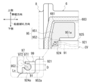
- FIG. 5 is an enlarged view of the area around the opening 95 that communicates the first chamber S1 and the second chamber S2.
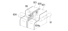
- FIG. 6 is a perspective view illustrating the locking portion 99 in the control valve CV. In FIG. 5, in order to make the position of the opening 95 easier to understand, the area of the opening 95 is shown with crossed hatching similar to the area of the joint 683.
- the opening 95 has a substantially L-shape when viewed from the front side of the vehicle (the front side in the drawing).
- the opening 95 has a first region 951 and a second region 952.
- the first region 951 extends inside the surrounding wall 681 in the vehicle width direction (in the left-right direction in the figure).
- the lower edge 951a of the first region 951 is located above the upper edge 925 of the control valve CV.
- the second region 952 extends from the first region 951 on the second cover 8 side (left side in the figure) to the lower side on the control valve CV side.
- a recess 924 is provided in the upper part on the second cover 8 side.
- the second region 952 of the opening 95 extends to the recess 924 of the control valve CV.
- the lower side 952a of the second region 952 is located at approximately the same height as the upper edge 924a of the recess 924 of the control valve CV.
- the control valve CV has a basic configuration in which a separate plate 920 is sandwiched between valve bodies 921, 921 (see FIG. 6).
- a separate plate 920 is sandwiched between valve bodies 921, 921 (see FIG. 6).
- the upper corner region of the separate plate 920 is exposed within the recess 924 .
- the area exposed in the recess 924 of the separate plate 920 is used as a locking part 99 for the electric wire 91 extending from the temperature sensor 90 (see FIG. 7).
- the locking portion 99 has a notch hole 97 .
- the notch hole 97 has a first region 971 and a second region 972.
- the first region 971 is a substantially circular region with an inner diameter slightly larger than the diameter D of the electric wire 91 .
- the second area 972 is a notched area in the upper part of the first area 971 on the second cover 8 side (left side in the figure).
- the second region 972 is formed with a gap Lx slightly smaller than the diameter D of the electric wire 91.
- the gap Lx is set to a width that allows the electric wire 91 extending toward the front side of the paper through the opening 95 (second region 952) to be inserted into the first region 971 from the second region 972.
- the locking portion 99 is provided to hold a region of the electric wire 91 disposed across the first chamber S1 and the second chamber S2, which is located within the second chamber S2. ing.
- FIG. 7 is a diagram illustrating the arrangement of the electric wires 91 in the first room S1.
- FIG. 8 is a diagram illustrating the dummy cover 21 that supports the electric wire 91.
- FIG. 9 is a diagram illustrating how the electric wire 91 is supported by the fixture 96.
- a mechanical oil pump MOP driven by a rotation transmission mechanism 150 is located in the housing section 68 (on the right side in the figure) when viewed from the strainer 10.
- the rotation transmission mechanism 150 includes a drive sprocket 151, a driven sprocket 152, and a chain 153.
- the drive sprocket 151 rotates around the rotation axis X1 by a rotational driving force input through the impeller sleeve 155 of the torque converter T/C.
- the impeller sleeve 155 is fitted onto the input shaft 20 of the forward/reverse switching mechanism 2 .
- the input shaft 20 is rotatably supported by a dummy cover 21 that closes an opening in the peripheral wall 641 .
- the drive sprocket 151 and the impeller sleeve 155 are rotatably supported by the input shaft 20 of the forward/reverse switching mechanism 2 .
- rotation input to drive sprocket 151 is transmitted to driven sprocket 152 via chain 153.
- the driven sprocket 152 rotates around the rotation axis X5 by the transmitted rotation.
- the rotating shaft of the mechanical oil pump MOP to which the driven sprocket 152 is connected rotates, thereby driving the mechanical oil pump MOP.
- the oil OL stored in the lower part of the case 6 is sucked through the strainer 10.
- the strainer 10 has a temperature sensor 90 (sensor, oil temperature sensor) for measuring the temperature of the oil OL sucked into the strainer 10.
- the temperature sensor 90 is attached to the side surface of the strainer 10.
- the temperature sensor 90 has a sensor portion 901 on the tip side disposed on the side of the suction port 11 of the strainer 10.
- the temperature sensor 90 is provided at a position where at least the sensor portion 901 is immersed in the oil OL stored in the oil storage portion 67.
- an electric wire 91 is connected to the sensor section 901 of the temperature sensor 90. As shown in FIG. 2, the other end of the electric wire 91 is connected to a connector portion 92 (see FIG. 4) that is connected to a mating connector 93. Electric wire 91 electrically connects temperature sensor 90 and connector section 92 . An output signal from the sensor unit 901 is output to an external processing device (for example, a control device for the power transmission device 1) via the electric wire 91.
- an external processing device for example, a control device for the power transmission device 1
- the connector portion 92 is connected to a mating connector 93 within the second chamber S2 that accommodates the control valve CV.
- the mating connector 93 is connected to a control device (not shown) and is also connected to an external connection terminal 98 via wiring 94 .
- the connection terminals 98 are exposed on the surface of the third cover 9. A connector on the vehicle side is connected to this connection terminal 98.
- the connector portion 92 is connected to the mating connector 93 within the second chamber S2 partitioned from the first chamber S1.
- the rotation transmission mechanism 150 described above is located on the second chamber S2 side (on the accommodating section 68 side where the connector section 92 is arranged) when viewed from the temperature sensor 90.
- the chain 153 of the rotation transmission mechanism 150 crosses the path Rm that connects the temperature sensor 90 and the accommodation portion 68 (opening 95: see FIG. 10) in the vertical line VL direction (vertical direction in the figure). Therefore, in the power transmission device 1 when viewed from the direction of the rotation axis X, it is necessary to route the electric wire 91 extending from the temperature sensor 90 to bypass the rotation transmission mechanism 150.
- the wiring route for the electric wire 91 includes a route 1 that detours around the upper side of the drive sprocket 151 and a route 2 that detours around the lower side of the driven sprocket 152.
- the electric wire 91 is pulled out from above the temperature sensor 90 in order to arrange the sensor part 901 facing downward.
- the peripheral wall portion 61 is arranged close to the second chamber S2 side (right side in the figure) of the rotation transmission mechanism 150, there is insufficient space to arrange the electric wire 91.
- the electric wire 91 is routed so as to bypass the upper side of the drive sprocket 151.
- FIG. 8 is a diagram illustrating the dummy cover 21 that supports the electric wire 91.
- FIG. 9 is a diagram illustrating how the electric wire 91 is supported by the fixture 96.
- a vertical line VL and a horizontal line HL based on the installation state of the power transmission device 1 in the vehicle are displayed in a superimposed manner.
- a peripheral wall portion 641 for forming a housing portion for the forward/reverse switching mechanism 2 is provided with an opening toward the front side (second cover 8) in the drawing.
- a dummy cover 21 (see FIG. 2) that closes the opening of the peripheral wall portion 641 is assembled to the peripheral wall portion 641 from the second cover 8 side and fixed with bolts BL, BL1, and BL2 (see FIG. 7).
- the dummy cover 21 has a peripheral portion 220 having bolt holes 221, 221A, and 221B.
- the inner side of the peripheral portion 220 is a cover portion 230 that covers the side surface of the forward/reverse switching mechanism 2 on the second cover 8 side (the front side in the drawing).
- An insertion hole 231 is opened in the center of the cover part 230.
- the dummy cover 21 is a plate-like member having a predetermined thickness in the direction of the rotation axis penetrate.
- bolt holes 221 are provided at intervals in the circumferential direction around the central axis (rotation axis X1).
- fixtures 96A and 96B for supporting the electric wire 91 are attached at two locations on the vehicle rear side relative to the vertical line VL passing through the center of the insertion hole 231 when viewed from the direction of the central axis (rotation axis X1). ing.
- These fixtures 96A and 96B are located above and below a horizontal line HL passing through the center of the insertion hole 231, respectively, on the front side of the vehicle (on the right side in the figure) with respect to the bolt hole 221A.
- a fixture 96C is also attached to the front side of the vehicle from the vertical line VL and above the horizontal line HL.
- fixtures 96A, 96B, and 96C are simply referred to as fixtures 96.
- the fixture 96 has a support part 962 having an insertion hole 962a for the electric wire 91 located on one side of a disc part 961, and four leg parts 963 on the other side. There is.
- the leg portion 963 is supported by the disk portion 961 in a cantilever manner.
- the distal end side of the leg portion 963 is elastically displaceable in the radial direction of the center line C96 of the fixture 96.
- the return part 963a provided in the leg part 963 is locked to the peripheral edge of the mounting hole 222, so that it can be removed from the mounting hole 222. It is attached to the peripheral edge part 220 in a state in which falling off is regulated.
- a rib 240 having an oil passage inside is located between the fixtures 96A and 96B in the vertical line VL direction.
- the rib 240 bulges further toward the front in the drawing than the peripheral portion 220 and the cover portion 230.
- the rib 240 is provided in a range that crosses the upper side of the insertion hole 231 in the horizontal direction.
- An end 240a of the rib 240 on the rear side of the vehicle is located on the rear side of the vehicle with respect to the fixtures 96A and 96B.
- the rib 240 is inclined so that its height in the direction of the vertical line VL decreases toward the rear of the vehicle (on the left side in the figure) from the boundary point 240c.
- the bolt hole 221A is located on the extension of the rib 240 on the end 240a side.
- the end portion 240a of the rib 240 is rounded.
- a region of the electric wire 91 between the fixtures 96A and 96B is in pressure contact with the rounded end 240a from the rear side of the vehicle.
- the rib 240 is inclined in such a direction that the height in the direction of the vertical line VL decreases on the vehicle front side from the boundary point 240c toward the end 240b on the vehicle front side.
- a fixture 96C is located above the rib 240 on the vehicle front side relative to the vertical line VL. Above the rib 240, the fixtures 96B and 96C are arranged at substantially the same height position in the vertical line VL direction. A bolt hole 221B is located above these fixtures 96B and 96C.
- the temperature sensor 90 is connected to a connector section 92 via an electric wire 91.
- the temperature sensor 90 is installed in the power transmission device 1 from the connector portion 92 side.
- a part of the wiring 94 attached to the control valve CV is connected to a mating connector 93.
- the connector portion 92 of the electric wire 91 extending from the temperature sensor 90 is connected to the mating connector 93.
- the electric wire 91 extending from the connector portion 92 is routed toward the second cover 8 side (the left side in the figure) where the opening 95 is located.
- a recess 924 is provided in an area overlapping with the opening 95 when viewed from the front side of the vehicle, and the separate plate 920 is engaged in the recess 924. Part 99 is exposed.
- the locking portion 99 has a notch hole 97.
- the notch hole 97 has a first region 971 for holding the electric wire 91 and a second region 972 that allows the electric wire 91 to be inserted into the first region 971.
- the electric wire 91 routed from the connector portion 92 side is hooked on the corner of the recess 924 of the control valve CV and routed to the opening 95 side. Then, the electric wire 91 is inserted into the first area 971 from the second area 972, and the electric wire 91 is locked in the notch hole 97 of the locking part 99. As a result, in the second chamber S2, the area between the connector portion 92 and the locking portion 99 of the electric wire 91 is arranged without significantly sagging.
- the electric wire 91 extending from the opening 95 is inserted into the mounting hole 222 of the dummy cover 21 by inserting the fixtures 96A, 96B, and 96C through which the electric wire 91 is inserted. , are fixed by fixtures 96A, 96B, and 96C.
- the fixtures 96B and 96C were inserted into the mounting holes 222 of the dummy cover 21, and then the area between the fixtures 96C and 96B in the electric wire 91 was screwed into the bolt hole 221B of the peripheral portion 220.
- upward displacement of the area between the fixture 96C and the fixture 96B in the electric wire 91 is regulated by the bolt BL2.
- the electric wire 91 is inserted into the end of the rib 240 from the rear side of the vehicle.
- the fixture 96A is attached to the dummy cover 21 while being brought into pressure contact with the dummy cover 240a.
- the temperature sensor 90 is locked to the locking piece 13 attached to the strainer 10, and the sensor part 901 of the temperature sensor 90 is connected to the oil OL in the oil storage part 67 on the side of the suction port 11. Place it in a position where it will be submerged in oil.
- the locking piece 13 is supported by a cantilever on the side surface of the strainer 10, and the tip of the locking piece 13 is elastic in the direction toward and away from the side surface of the strainer 10 (the installation surface of the temperature sensor 90). Displaceable. Therefore, the temperature sensor 90 can be easily attached to the side surface of the strainer 10.
- the electric wire 91 When the electric wire 91 is routed in this manner, the electric wire 91 extending from the temperature sensor 90 is arranged along the peripheral edge 220 of the dummy cover 21. Thereby, the electric wire 91 is arranged in a substantially arc shape along the outer periphery of the drive sprocket 151 (see FIG. 7) supported by the dummy cover 21. That is, when viewed from the rotation axis X1, the electric wire 91 bypasses the other rotation axes X2, X3, and X4, and passes through the area between the rotation axis X and the other rotation axes X2, X3, and X4. , are arranged from the bottom to the top of the case 6.
- the electric wire 91 is positioned by the fixtures 96A, 96B, and 96C, and also between the bolt BL1 and the rib 240. Thereby, the electric wire 91 is firmly supported by the dummy cover 21, and the electric wire 91 is prevented from interfering with surrounding rotating bodies.
- the electric wire 91 drawn out from the temperature sensor 90 to the upper part of the case 6 passes above the rotation axis X1 in the direction of the vertical line VL, and is drawn out into the second chamber S2.
- the connector portion 92 of the electric wire 91 connected to the end opposite to the temperature sensor 90 is connected to the mating connector 93 at the upper part of the second chamber S2.
- oil OL is not stored in the area where the electric wire 91 is routed in the second chamber S2, so the oil OL interferes with the connection between the connector part 92 and the mating connector 93. It is designed not to.
- the power transmission device 1 is a power transmission mechanism having a plurality of rotating elements; a housing HS (case) that houses the power transmission mechanism; a temperature sensor 90 (sensor) disposed at the lower part of the housing HS; An electric wire 91 that electrically connects the temperature sensor 90 and the connector section 92 is provided.
- the temperature sensor 90 is arranged in the oil reservoir 67 at the bottom of the housing HS.
- the electric wire 91 is routed through the plurality of rotating elements to the upper part of the housing HS, and the connector part 92 is disposed at the upper part of the housing HS.
- the temperature sensor 90 located at the lower part of the housing HS and the connector section 92 located at the upper part of the housing HS are connected by the electric wire 91 routed between the plurality of rotating elements. be done.
- the electric wire 91 is routed by bypassing the plurality of rotating elements, the overall length of the electric wire 91 becomes longer, and the housing HS becomes larger because the electric wire 91 is routed by bypassing the plurality of rotating elements.
- the housing HS has a region 651 that serves as a housing portion for housing the forward/reverse switching mechanism 2 (first rotating element).
- the electric wire 91 is supported by a dummy cover 21 (cover member) that closes the opening of the region 651 and covers the sides of the forward/reverse switching mechanism 2 .
- the housing HS has a first chamber S1 that houses the power transmission mechanism, and a second chamber S2 that houses the control valve CV that is a control unit of the power transmission mechanism.
- the temperature sensor 90 is arranged in the oil storage section 67 at the lower part of the first chamber S1.
- the connector portion 92 is arranged in the second chamber S2.
- the electric wire 91 is routed between the upper part of the first chamber S1 and the second chamber S2.
- the electric wire 91 that passes between the plurality of rotating elements in the first chamber S1 and is routed from the bottom to the top of the first chamber S1 is routed as it is to the second chamber S2, and is connected to the connector.
- the section 92 is arranged in the second chamber S2.
- the total length of the electric wire 91 can be made shorter than when the electric wire 91 is routed to the second chamber S2 by detouring around the outside of the plurality of rotating elements.
- the housing HS has a partition wall 685 (partition wall portion) that partitions the first chamber S1 and the second chamber S2.
- An opening 95 is provided at the top of the partition wall 685 to communicate the first chamber S1 and the second chamber S2.
- the electric wire 91 can be routed between the upper part of the first chamber S1 and the second chamber S2 without making a detour around the outside of the housing HS.
- the power transmission device 1 becomes larger by the amount of the electric wire 91 that is routed around the outside.
- the housing HS includes a surrounding wall 681 that surrounds the area of the second chamber S2, and a third cover 9 (cover) that closes the opening of the surrounding wall 681.
- the surrounding wall 681 is provided with an opening facing toward the front of the vehicle based on the state in which the power transmission device 1 is installed in the vehicle.
- the second chamber S2 in which the connector portion 92 is arranged opens toward the front side of the vehicle.
- the second chamber S2 can be accessed simply by removing the third cover 9, the work of connecting the connector part 92 of the electric wire 91 in the second chamber S2 to the mating connector 93 located in the second chamber S2 is unnecessary. Easy to implement.
- the control valve CV is provided with a locking portion 99 for the electric wire 91 routed through the opening 95 between the first chamber S1 and the second chamber S2.
- the electric wire 91 located in the second chamber S2 can be supported by the control valve CV. Thereby, there is no need to separately prepare a component for supporting the electric wire 91 in the second chamber S2. If separate parts are prepared, there are concerns that the size of the second chamber S2 and the weight of the power transmission device 1 will increase, but such situations can be preferably prevented from occurring.
- the control valve CV (control unit) has a basic configuration in which a separate plate 920 is sandwiched between valve bodies 921, 921.
- the locking portion 99 is a notch hole 97 (notch portion) provided in the separate plate 920.
- the locking portion can be provided more easily by providing the notch hole 97 corresponding to the locking portion in the separate plate 920 than by providing the locking portion in the main body of the valve body 921.
- valve bodies 921, 921 are provided with a recess 924 that exposes the region of the notch hole 97 of the separate plate 920.
- the recess 924 and the region of the notch hole 97 are provided in an overlapping positional relationship.
- the separate plate 920 With this configuration, there is no need for the separate plate 920 to protrude significantly from the valve bodies 921, 921 in order to lock the electric wire 91 in the notch hole 97 of the separate plate 920. In such a case, the separate plate 920 becomes large. When the separate plate 920 becomes larger, the housing HS also becomes larger. As described above, by providing the recesses 924, 924 on the valve bodies 921, 921 side, it is possible to provide a locking part for the electric wire 91 without increasing the size of the control valve CV, which increases the size of the housing HS. can be suitably prevented.
- the electric wire 91 is connected using the rib 240 (protrusion) that protrudes from the dummy cover 21 toward the second cover 8 side and the bolt BL1 that fixes the dummy cover 21 to the housing HS (case 6). , is positioned.
- the electric wire 91 can be gripped and provided between the bolt BL1 and the rib 240, so the electric wire 91 can be held at a predetermined position on the dummy cover 21. Furthermore, it is possible to reduce the number of fixtures 96 used to support the electric wires 91 on the dummy cover 21 when routing the electric wires 91 extending from the temperature sensor 90 to avoid interference with the components of the rotation transmission mechanism 150. can.
- the input shaft (rotary shaft X1) of the power transmission mechanism and the output shaft (rotary shaft X4) of the power transmission mechanism are located apart in the longitudinal direction of the vehicle along the horizontal line HL direction. .
- the strainer 10 is arranged between the input shaft (rotary shaft X1) and the output shaft (rotary shaft X2) when viewed from the direction of the rotary shaft X of the power transmission device 1.
- the temperature sensor 90 is an oil temperature sensor disposed in the lower oil storage section 67 in the housing HS (first chamber S1). A temperature sensor 90 is attached to the strainer 10.
- the temperature sensor 90 can be attached to the strainer 10 that is submerged in the oil OL in the oil storage section 67, so the temperature sensor 90 can be reliably submerged in the oil OL. Thereby, the temperature sensor 90 can appropriately measure the temperature of the oil OL in the oil storage section 67. Moreover, since the strainer 10 is supported at two points, the mechanical oil pump MOP and the partition wall portion 62, the support stability is high. By attaching the temperature sensor 90 to the strainer 10 with high support stability, the installation stability of the temperature sensor 90 can be ensured.
- a locking piece 13 supported in a cantilever by the main body of the strainer 10 is provided on the side surface of the strainer 10 on the second cover 8 side.
- the temperature sensor 90 is held between the main body of the strainer 10 and the locking piece 13.
- the temperature sensor 90 is arranged with the sensor section 901 facing downward. When viewed from the second cover 8 side, the sensor section 901 is provided in a positional relationship overlapping the suction port 11 of the strainer 10 .
- Electric wire 91 is connected to the top of temperature sensor 90 .
- the temperature sensor 90 can be easily attached to the strainer 10. Furthermore, since the sensor section 901 is disposed near the oil OL suction port 11, the temperature of the oil OL sucked into the strainer 10 can be appropriately measured. Since the oil OL sucked into the strainer 10 is used for driving and lubricating the power transmission mechanism, the temperature of the oil OL supplied to the power transmission mechanism can be appropriately detected.
- a transmission mechanism 150 is provided.
- the drive sprocket 151 is rotatably supported by the dummy cover 21.
- the electric wire 91 supported by the dummy cover 21 is routed from the bottom to the top of the first chamber S1 along the outer periphery of the drive sprocket 151.
- the electric wire 91 extending from the temperature sensor 90 can be routed while avoiding interference with the components of the rotation transmission mechanism 150.
- the rotation transmission mechanism 150 includes a pair of rotating bodies (drive sprocket 151, driven sprocket 152) and a chain 153 wound around the pair of rotating bodies (drive sprocket 151, driven sprocket 152). .
- the pair of rotating bodies are chain sprockets.
- the chain 153 of the rotation transmission mechanism 150 crosses the path Rm that connects the temperature sensor 90 and the housing section 68 (opening section 95) in the direction of the vertical line VL.
- the rotation transmission mechanism 150 is disposed across the path that routes the electric wire 91 extending from the temperature sensor 90 in the shortest distance toward the second chamber S2, the rotation transmission mechanism 150 is configured as described above.
- the electric wire 91 can be appropriately routed while avoiding interference with the components of the electric wire 91.
- FIG. 11 is a schematic diagram illustrating a power transmission device 1A according to a modification.
- the power transmission device 1A may employ a case 6A in which the first chamber S1 and the second chamber S2 communicate with each other through an opening 95A.
- the control valve CV is arranged to close the opening 95A and partition the first chamber S1 and the second chamber S2. Even with the power transmission device 1A having such a configuration, it is possible to prevent the power transmission device 1A from increasing in size, create a spatial margin in the housing HS, and improve layout properties in the housing HS. .
- the case where the electric wire 91 extending from the temperature sensor 90 is arranged is illustrated, but for example, the electric wire extending from the sensor (rotation sensor) that detects the rotation of the input shaft 20 of the forward/reverse switching mechanism 2 may be arranged.
- the electric wire 91 extending from the temperature sensor 90 and the electric wire extending from the rotation sensor may be bundled, and support by the dummy cover 21 or support by the locking portion 99 may be used for routing the bundled wiring.
- the power transmission device 1 transmits the rotation of the engine ENG to the drive wheels WH, WH is illustrated, but the power transmission device 1 transmits the rotation of the engine ENG and the motor (rotating electric machine).
- the rotation may be transmitted to the drive wheels WH, WH.
- a one-motor, two-clutch type (the motor is arranged between the engine ENG and the power transmission device, the first clutch is arranged between the engine ENG and the motor, and the second clutch is arranged inside the power transmission device 1)
- It may also be a power transmission device of the following type.
- the power transmission device 1 has a speed change function, but the power transmission mechanism does not have a speed change function and simply decelerates (or may speed up). It's okay. If the power transmission device does not have a speed change function and is configured to decelerate the rotation of the motor and transmit it to the drive wheels WH, the oil OL for cooling the motor and the deceleration A hydraulic control circuit for supplying oil OL for lubricating the mechanism is arranged in the second chamber S2 together with the electric oil pump EOP. Further, in the above embodiment, the control unit of the power transmission device 1 is provided with the control valve CV, but the power transmission device 1 does not have a speed change mechanism, and the drive source is not the engine ENG. In the case of a motor (rotating electric machine), it may be a control unit including an inverter or the like that drives and controls the motor.
Landscapes
- Engineering & Computer Science (AREA)
- General Engineering & Computer Science (AREA)
- Mechanical Engineering (AREA)
- Oil, Petroleum & Natural Gas (AREA)
- General Details Of Gearings (AREA)
Priority Applications (3)
| Application Number | Priority Date | Filing Date | Title |
|---|---|---|---|
| CN202380028167.6A CN118974446A (zh) | 2022-03-23 | 2023-03-23 | 动力传递装置 |
| JP2024509228A JP7592377B2 (ja) | 2022-03-23 | 2023-03-23 | 動力伝達装置 |
| US18/846,954 US12516729B2 (en) | 2022-03-23 | 2023-03-23 | Power transmission device |
Applications Claiming Priority (2)
| Application Number | Priority Date | Filing Date | Title |
|---|---|---|---|
| JP2022047608 | 2022-03-23 | ||
| JP2022-047608 | 2022-03-23 |
Publications (1)
| Publication Number | Publication Date |
|---|---|
| WO2023182449A1 true WO2023182449A1 (ja) | 2023-09-28 |
Family
ID=88101659
Family Applications (1)
| Application Number | Title | Priority Date | Filing Date |
|---|---|---|---|
| PCT/JP2023/011612 Ceased WO2023182449A1 (ja) | 2022-03-23 | 2023-03-23 | 動力伝達装置 |
Country Status (4)
| Country | Link |
|---|---|
| US (1) | US12516729B2 (https=) |
| JP (1) | JP7592377B2 (https=) |
| CN (1) | CN118974446A (https=) |
| WO (1) | WO2023182449A1 (https=) |
Cited By (2)
| Publication number | Priority date | Publication date | Assignee | Title |
|---|---|---|---|---|
| US20250207661A1 (en) * | 2022-03-23 | 2025-06-26 | Jatco Ltd | Power transmission device |
| US20250224029A1 (en) * | 2022-03-23 | 2025-07-10 | Jatco Ltd | Power transmission device |
Families Citing this family (1)
| Publication number | Priority date | Publication date | Assignee | Title |
|---|---|---|---|---|
| JP7584878B2 (ja) * | 2022-03-23 | 2024-11-18 | ジヤトコ株式会社 | 動力伝達装置および油圧装置 |
Citations (6)
| Publication number | Priority date | Publication date | Assignee | Title |
|---|---|---|---|---|
| JPH09145487A (ja) * | 1995-11-17 | 1997-06-06 | Mazda Motor Corp | 自動変速機の油温検出装置取付構造 |
| JP2016223452A (ja) * | 2013-09-18 | 2016-12-28 | アイシン・エィ・ダブリュ株式会社 | 車両用駆動装置 |
| JP2018103977A (ja) * | 2016-12-26 | 2018-07-05 | Ntn株式会社 | インホイールモータ駆動装置 |
| JP2018179253A (ja) * | 2017-04-20 | 2018-11-15 | マツダ株式会社 | 自動変速機のバルブボディ構造 |
| JP2019065885A (ja) * | 2017-09-28 | 2019-04-25 | ダイハツ工業株式会社 | 変速機におけるセンサ保持構造および配線処理構造 |
| WO2021015205A1 (ja) * | 2019-07-25 | 2021-01-28 | ジヤトコ株式会社 | 動力伝達装置 |
Family Cites Families (4)
| Publication number | Priority date | Publication date | Assignee | Title |
|---|---|---|---|---|
| US5662007A (en) * | 1993-05-12 | 1997-09-02 | Siemens Aktiengesellschaft | Motor vehicle gearbox control system in an oil-filled casing |
| DE9307228U1 (de) * | 1993-05-12 | 1993-07-15 | Siemens AG, 8000 München | Steuersystem, insbesondere Getriebesteuerungssystem für ein Kraftfahrzeug |
| JP3980292B2 (ja) * | 2001-05-08 | 2007-09-26 | ジヤトコ株式会社 | 自動変速機の車速センサ取付構造 |
| KR102852658B1 (ko) * | 2020-01-08 | 2025-08-29 | 현대모비스 주식회사 | 그로멧 및 와이어 정렬 장치 |
-
2023
- 2023-03-23 WO PCT/JP2023/011612 patent/WO2023182449A1/ja not_active Ceased
- 2023-03-23 JP JP2024509228A patent/JP7592377B2/ja active Active
- 2023-03-23 US US18/846,954 patent/US12516729B2/en active Active
- 2023-03-23 CN CN202380028167.6A patent/CN118974446A/zh active Pending
Patent Citations (6)
| Publication number | Priority date | Publication date | Assignee | Title |
|---|---|---|---|---|
| JPH09145487A (ja) * | 1995-11-17 | 1997-06-06 | Mazda Motor Corp | 自動変速機の油温検出装置取付構造 |
| JP2016223452A (ja) * | 2013-09-18 | 2016-12-28 | アイシン・エィ・ダブリュ株式会社 | 車両用駆動装置 |
| JP2018103977A (ja) * | 2016-12-26 | 2018-07-05 | Ntn株式会社 | インホイールモータ駆動装置 |
| JP2018179253A (ja) * | 2017-04-20 | 2018-11-15 | マツダ株式会社 | 自動変速機のバルブボディ構造 |
| JP2019065885A (ja) * | 2017-09-28 | 2019-04-25 | ダイハツ工業株式会社 | 変速機におけるセンサ保持構造および配線処理構造 |
| WO2021015205A1 (ja) * | 2019-07-25 | 2021-01-28 | ジヤトコ株式会社 | 動力伝達装置 |
Cited By (4)
| Publication number | Priority date | Publication date | Assignee | Title |
|---|---|---|---|---|
| US20250207661A1 (en) * | 2022-03-23 | 2025-06-26 | Jatco Ltd | Power transmission device |
| US20250224029A1 (en) * | 2022-03-23 | 2025-07-10 | Jatco Ltd | Power transmission device |
| US12504065B2 (en) * | 2022-03-23 | 2025-12-23 | Jatco Ltd | Power transmission device |
| US12553512B2 (en) * | 2022-03-23 | 2026-02-17 | Jatco Ltd | Power transmission device |
Also Published As
| Publication number | Publication date |
|---|---|
| US12516729B2 (en) | 2026-01-06 |
| JPWO2023182449A1 (https=) | 2023-09-28 |
| US20250224032A1 (en) | 2025-07-10 |
| JP7592377B2 (ja) | 2024-12-02 |
| CN118974446A (zh) | 2024-11-15 |
Similar Documents
| Publication | Publication Date | Title |
|---|---|---|
| WO2023182449A1 (ja) | 動力伝達装置 | |
| JP7584879B2 (ja) | 動力伝達装置 | |
| JP5041249B2 (ja) | 車両用駆動装置 | |
| WO2023182447A1 (ja) | 動力伝達装置 | |
| US12331829B2 (en) | Power transmission device | |
| JP7580900B2 (ja) | 動力伝達装置 | |
| JP7604087B2 (ja) | 動力伝達装置 | |
| JP2016223452A (ja) | 車両用駆動装置 | |
| JP7596055B2 (ja) | 動力伝達装置 | |
| JP7580901B2 (ja) | 動力伝達装置 | |
| JP7618375B2 (ja) | 動力伝達装置 | |
| KR102113129B1 (ko) | 자동 변속기 | |
| US20250067333A1 (en) | Power transmission device and hydraulic device | |
| WO2023182450A1 (ja) | 動力伝達装置 | |
| WO2023182446A1 (ja) | 動力伝達装置 | |
| US12140222B2 (en) | Power transmission device | |
| CN115817158A (zh) | 动力传递装置 | |
| EP4692602A1 (en) | Vehicle drive device | |
| JP2023141341A (ja) | 動力伝達装置 | |
| WO2023182452A1 (ja) | 動力伝達装置 | |
| US12578012B2 (en) | Oil accumulation portion in a cover member of a drive device | |
| JP7849287B2 (ja) | 変速機ケース、コントロールバルブ、並びに変速機 | |
| JP2023154845A (ja) | 動力伝達装置 |
Legal Events
| Date | Code | Title | Description |
|---|---|---|---|
| 121 | Ep: the epo has been informed by wipo that ep was designated in this application |
Ref document number: 23775043 Country of ref document: EP Kind code of ref document: A1 |
|
| DPE1 | Request for preliminary examination filed after expiration of 19th month from priority date (pct application filed from 20040101) | ||
| WWE | Wipo information: entry into national phase |
Ref document number: 18846954 Country of ref document: US |
|
| WWE | Wipo information: entry into national phase |
Ref document number: 202380028167.6 Country of ref document: CN |
|
| ENP | Entry into the national phase |
Ref document number: 2024509228 Country of ref document: JP Kind code of ref document: A |
|
| NENP | Non-entry into the national phase |
Ref country code: DE |
|
| 122 | Ep: pct application non-entry in european phase |
Ref document number: 23775043 Country of ref document: EP Kind code of ref document: A1 |
|
| WWP | Wipo information: published in national office |
Ref document number: 18846954 Country of ref document: US |
|
| WWG | Wipo information: grant in national office |
Ref document number: 18846954 Country of ref document: US |