WO2023181574A1 - 入力装置およびその制御方法、プログラム - Google Patents
入力装置およびその制御方法、プログラム Download PDFInfo
- Publication number
- WO2023181574A1 WO2023181574A1 PCT/JP2022/048240 JP2022048240W WO2023181574A1 WO 2023181574 A1 WO2023181574 A1 WO 2023181574A1 JP 2022048240 W JP2022048240 W JP 2022048240W WO 2023181574 A1 WO2023181574 A1 WO 2023181574A1
- Authority
- WO
- WIPO (PCT)
- Prior art keywords
- group
- setting
- operators
- input device
- sound
- Prior art date
- Legal status (The legal status is an assumption and is not a legal conclusion. Google has not performed a legal analysis and makes no representation as to the accuracy of the status listed.)
- Ceased
Links
Images


Classifications
-
- G—PHYSICS
- G10—MUSICAL INSTRUMENTS; ACOUSTICS
- G10H—ELECTROPHONIC MUSICAL INSTRUMENTS; INSTRUMENTS IN WHICH THE TONES ARE GENERATED BY ELECTROMECHANICAL MEANS OR ELECTRONIC GENERATORS, OR IN WHICH THE TONES ARE SYNTHESISED FROM A DATA STORE
- G10H1/00—Details of electrophonic musical instruments
- G10H1/32—Constructional details
- G10H1/34—Switch arrangements, e.g. keyboards or mechanical switches specially adapted for electrophonic musical instruments
-
- G—PHYSICS
- G10—MUSICAL INSTRUMENTS; ACOUSTICS
- G10H—ELECTROPHONIC MUSICAL INSTRUMENTS; INSTRUMENTS IN WHICH THE TONES ARE GENERATED BY ELECTROMECHANICAL MEANS OR ELECTRONIC GENERATORS, OR IN WHICH THE TONES ARE SYNTHESISED FROM A DATA STORE
- G10H1/00—Details of electrophonic musical instruments
- G10H1/0008—Associated control or indicating means
-
- G—PHYSICS
- G10—MUSICAL INSTRUMENTS; ACOUSTICS
- G10H—ELECTROPHONIC MUSICAL INSTRUMENTS; INSTRUMENTS IN WHICH THE TONES ARE GENERATED BY ELECTROMECHANICAL MEANS OR ELECTRONIC GENERATORS, OR IN WHICH THE TONES ARE SYNTHESISED FROM A DATA STORE
- G10H2220/00—Input/output interfacing specifically adapted for electrophonic musical tools or instruments
- G10H2220/091—Graphical user interface [GUI] specifically adapted for electrophonic musical instruments, e.g. interactive musical displays, musical instrument icons or menus; Details of user interactions therewith
- G10H2220/101—Graphical user interface [GUI] specifically adapted for electrophonic musical instruments, e.g. interactive musical displays, musical instrument icons or menus; Details of user interactions therewith for graphical creation, edition or control of musical data or parameters
- G10H2220/116—Graphical user interface [GUI] specifically adapted for electrophonic musical instruments, e.g. interactive musical displays, musical instrument icons or menus; Details of user interactions therewith for graphical creation, edition or control of musical data or parameters for graphical editing of sound parameters or waveforms, e.g. by graphical interactive control of timbre, partials or envelope
-
- G—PHYSICS
- G10—MUSICAL INSTRUMENTS; ACOUSTICS
- G10H—ELECTROPHONIC MUSICAL INSTRUMENTS; INSTRUMENTS IN WHICH THE TONES ARE GENERATED BY ELECTROMECHANICAL MEANS OR ELECTRONIC GENERATORS, OR IN WHICH THE TONES ARE SYNTHESISED FROM A DATA STORE
- G10H2220/00—Input/output interfacing specifically adapted for electrophonic musical tools or instruments
- G10H2220/155—User input interfaces for electrophonic musical instruments
- G10H2220/221—Keyboards, i.e. configuration of several keys or key-like input devices relative to one another
Definitions
- the present invention relates to an input device, a control method thereof, and a program.
- Patent Document 1 does not disclose how to set the sound parameters.
- a user may want to set a desired sound parameter to a desired operator.
- the operation of setting sound parameters one by one for each operator is complicated.
- a right-handed user and a left-handed user want to use the same device. Therefore, it is desirable to be able to perform sound parameter setting operations efficiently.
- One object of the present invention is to provide an input device that can facilitate sound parameter setting operations.
- a first group includes a plurality of operators
- a second group includes a plurality of operators arranged at symmetrical positions with respect to the plurality of operators included in the first group.
- an instruction receiving unit that receives a sound parameter setting instruction, and in response to the reception of the setting instruction, sets at least one set of controls that are symmetrically positioned with respect to each other.
- a control unit that executes a setting process for setting sound parameters as a target, and the control unit sets sound parameters for the first group of operators in the set of setting targets as the setting process. or execute a first process that causes the sound parameters set for the first group of operators and the operations of the second group to be reflected on the second group of operators in the set to be set.
- An input device is provided that executes a second process of exchanging sound parameters set for a child.
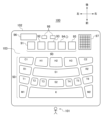
- FIG. 1 is a plan view of an input device according to a first embodiment.
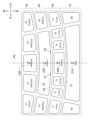
- FIG. 3 is a plan view of a pad operation section.
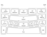
- FIG. 3 is a plan view of a pad operation section.
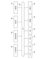
- FIG. 2 is a block diagram of an input device. It is a figure which shows the example of a display of a display part at the time of setting "group which can be a setting target.”
- FIG. 3 is a diagram showing functional blocks that implement sound parameter setting processing. It is a flowchart which shows sound parameter setting processing. It is a top view of the pad operation part of a modification.
- FIG. 3 is a perspective view of an input device according to a second embodiment.
- FIG. 1 is a plan view of an input device according to a first embodiment of the invention.
- the input device 100 is an input device suitable for inputting performance operations, and is configured as an electronic musical instrument (electronic percussion instrument), for example.
- the input device 100 is a device for setting or inputting sound parameters.
- the input device 100 has a housing 102.
- a panel 103 is provided on the upper surface side of the housing 102.
- a pad operation section 50, a setting operation section 90, a display section 96, and a speaker 97 are arranged on the panel 103.
- the setting operation unit 90 is an instruction receiving unit that includes an operator that receives sound parameter setting instructions (or input instructions) from the user 101.
- the setting operation section 90 includes a menu button 91, an interlock mode enable/disable button 92 (designation section), a swap mode enable/disable button 93 (designation section), a swap execution button 94, a decision button 95, and an increase/decrease button 98.
- the pad operation unit 50 is an operation reception unit that includes a plurality of operators (hereinafter referred to as pads) for the user 101 to input performance information.
- the plurality of pads included in the pad operation section 50 include pads K, H1 to H3, C1, C2, S1, S2, R1, R2, M1, M2, and T1 to T6.
- the user 101 normally uses the input device 100 in a position where the pad K is on the front side, as shown in FIG.
- the front side as viewed from the user 101 will be referred to as the front side
- the back side as the rear side and the left and right directions will also be referred to as the direction viewed from the user 101.
- Each pad has a different shape, the basic configuration is the same.
- Each pad is a physical switch that constitutes an input area for input operations (performance operations).
- Each pad has a top sheet, a base plate (not shown), and a sensor (not shown).
- the base plate is, for example, a metal plate or a plastic plate.
- a sensor is placed on the base plate, and a top sheet is placed on top of the sensor.
- the topsheet constitutes the surface of the pad.
- the surface of the pad is flat and exposed from the panel 103.
- the user 101 usually hits a pad with his or her finger when performing an input operation.
- a rubber plate for example, is used as the top sheet.
- the above sensor detects an input operation by the user 101.
- the above sensor is provided for each pad.
- the above-mentioned sensor is, for example, a pressure sensor that detects a change in pressure applied to a corresponding pad.
- the sensor outputs a signal with an amplitude corresponding to a change in pressure as information indicating an input operation.
- the above sensor is not limited to a pressure sensor, but may be a vibration sensor.
- each pad is configured as follows.
- a conductive pattern on a substrate, a conductive sheet, and a rubber sheet are arranged in order from the bottom. There is a spacer under the conductive sheet, and even when the rubber sheet is placed on it, the conductive pattern and the conductive sheet are not electrically connected or are only slightly electrically conductive.
- pressure is applied from above by tapping (or pushing) the rubber sheet with a finger, the conductive sheet is pushed and comes into contact with the conductive pattern, and the voltage value changes depending on the contact area.
- By detecting the voltage value with the above-mentioned sensor, it is possible to detect the force with which the finger is tapped (or pressed).
- Each pad is assigned an electronic tone, for example, a drum (which may also include percussion) tone.
- the tone of the electronic sound that can be assigned does not matter.
- the speaker 97 emits a tone corresponding to the pad.
- the tone color assigned to each pad can be changed. Note that the tones assigned to some pads may remain unchanged (fixed).
- FIG. 2 is a plan view of the pad operation section 50.
- the pad operation section 50 has a first region 10, a second region 20, a third region 30, and a fourth region 40.
- the direction in which the first, second, third, and fourth regions are arranged is the front-back direction.
- the direction perpendicular to the arrangement direction is the left-right direction.
- the first region 10, the fourth region 40, the second region 20, and the third region 30 are arranged in order in the direction away from the first region 10 (rearward).
- a fourth region 40 exists between the first region 10 and the third region 30.
- the shapes of the first region 10, the second region 20, and the third region 30 are different from each other.
- the first region 10 and the second region 20 are adjacent to each other in the front-back direction.
- the first area 10 mainly includes one or more pads to which a bass drum tone is assigned, and includes pads K, M1, and M2 as an example.
- the second area 20 mainly includes one or more pads to which a snare drum tone is assigned, and includes pads S1, R1, and R2 as an example.
- the third area 30 mainly includes one or more pads to which cymbal tones are assigned, and includes pads H1 to H3, C1, and C2 as an example.
- the fourth area 40 mainly includes one or more pads to which a Tom tone is assigned, and includes pads S2 and T1 to T6 as an example.
- P0 is a virtual straight line passing through G10, G40, G20, and G30 when viewed from above.
- the virtual straight line P0 is also the center line of the pad operation section 50 in the left-right direction.
- the virtual straight line P0 is also the center line of each of the first region 10, second region 20, third region 30, and fourth region 40 in the left-right direction.
- the input device 100 is assumed to be operated by either a right-handed person or a left-handed person, and is also assumed to be operated by both hands. Therefore, the entire pad is laid out in left-right symmetrical layout with the virtual straight line P0 as the center.
- pads K, S2, S1, and H2 are arranged at the center in the left-right direction.
- the pads T1, T2, and T3 and the pads T6, T5, and T4 are each line-symmetrical with respect to the virtual straight line P0 (centered on the virtual straight line P0).
- the pads M1, R1, C1 and the pads M2, R2, C2 are line symmetrical with respect to the virtual straight line P0.
- Pad H1 and pad H3 are line symmetrical with respect to virtual straight line P0.
- the boundary line 51 between the first area 10 and the fourth area 40, the boundary line 53 between the second area 20 and the third area 30, and the boundary line 52 between the fourth area 40 and the second area 20 are Both curves are convex toward the front. Furthermore, when viewed from above, the opposing end surfaces of the pads that are adjacent to each other in the left and right direction are straight lines, and are inclined so that the farther back they are, the closer they are to the imaginary straight line P0. The inclination of the end face and the curvature of the boundary line facilitate musical performance input in a comfortable and natural posture.
- the pad S1 is provided with convex portions 61 and 62 that protrude upward. By touching either of the convex portions 61, 62, the user can recognize the position of the pad S1 without relying on vision.
- FIG. 3 is a plan view of the pad operation section 50.
- a pair of controls (pads) that are symmetrically positioned with each other is called a "set".
- the pad group on the left is the first group GrL
- the pad group on the right is the second group GrR.
- the first group GrL includes pads T1, T2, T3, M1, R1, C1, and H1.
- the second group GrR includes pads T6, T5, T4, M2, R2, C2, and H3.
- FIG. 4 is a block diagram of the input device 100.
- Performance information generated by operating each pad in the pad operating section 50 and operation information generated by operating each operator in the setting operating section 90 are sent to the CPU 81 via the bus 80.
- the display section 96 is composed of an LCD or the like, and displays various information according to instructions from the CPU 81.
- the CPU 81 is connected via a bus 80 to a sound generating section 79, a ROM 82, a RAM 83, a timer 84, a storage section 85, and various I/Fs (interfaces) 86.
- the CPU 81 controls the entire device.
- the ROM 82 stores control programs executed by the CPU 81 and various data.
- the RAM 83 provides a work area when the CPU 81 executes a control program.
- the storage unit 85 includes a nonvolatile memory and stores various information.
- the various I/Fs 86 may include a MIDI (Musical Instrument Digital Interface) in addition to a wired or wireless communication I/F.
- the sound generating section 79 includes a speaker 97 (FIG. 1), a sound source circuit, and an effect circuit (not shown), and generates sounds based on performance information generated by operating each pad.
- the sound parameter setting modes include a "link mode” and a “swap mode.” These setting modes are applied to sets of pads that are symmetrically positioned with respect to each other.
- the set to which the setting mode is applied is called the "setting target set.”
- the sound parameter settings for the pads of the first group GrL are set for the pads of the second group GrR (or the first group GrL), which are arranged symmetrically with respect to the pads in the target group.
- the exchange mode is to exchange the sound parameters set for the pads of the first group GrL and the sound parameters set for the pads of the second group GrR, which are arranged symmetrically with the relevant pads, in the set to be set. This is a mode in which a replacement process (second process) is executed.
- Validity/invalidity of the interlocking mode can be specified by a user operation on the interlock mode valid/invalid button 92
- validation/invalidity of the exchange mode can be specified by a user operation on the exchange mode valid/invalid button 93.
- the user can instruct execution of linked processing by pressing the enter button 95 while inputting sound parameter candidates to be set. For example, if pad H1 and pad H3 are a pair to be set, and the linked mode is enabled, when the first sound parameter is assigned to pad H1, the first sound parameter is automatically assigned to pad H3. Sound parameters are assigned. The opposite is also true.
- pad C1 and pad C2 are the set to be set, and the swap mode is enabled.
- the second sound parameter is assigned to pad C1
- the second sound parameter is assigned to pad C1.
- the first sound parameter is assigned to C2.
- the assigned sound parameters are exchanged between pads C1 and C2.
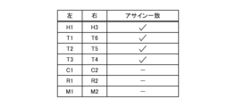
- FIG. 5 is a diagram showing an example of the display on the display unit 96 when setting "groups that can be set targets.”
- the groups that can be set are set by the user's operations on the menu button 91, increase/decrease button 98, enter button 95, etc. By marking "assignment matching", the user can set possible sets of settings. For example, in the example of FIG. 5, pads H1 and H3, pads T1 and T6, pads T2 and T5, and pads C1 and C2 are set as a set that can be set. Note that the "groups that can be set targets" may be set separately in the interlocking mode and the exchange mode.
- the method for setting the sets that can be set is not limited to this method, and it is not essential to use screen display. Furthermore, all pads or some pads may be fixedly treated as a set that can be set, regardless of user operations.
- the interlocking direction may be unidirectional instead of both directions.
- the interlocking direction may be determined in advance, or may be set by user operation.
- groups for which mutually different sound parameters are set before receiving the setting instruction may be excluded from the groups to be set.
- the method for determining the set of settings in the linked mode is not limited to this example. That is, other methods may be used as long as it is possible to achieve a state in which one pad is selected from among a plurality of pads. For example, the user may hit a desired pad with a force greater than a threshold, or the user may select a desired pad using the UI.
- the interlocking process in the interlocking mode is executed, for example, when the user performs an operation to set sound parameters (including changing settings). That is, in the linked mode, when an instruction to set a sound parameter for one of the pads in the group to be set is accepted as a setting instruction, the linked process is executed as the setting process.
- the sound parameter setting instruction is accepted when the user operates the menu button 91, increase/decrease button 98, enter button 95, etc.
- swapping processing is executed as a setting process. For example, when the exchange execution button 94 is pressed, an instruction to execute exchange of sound parameters is accepted.
- One or more sound parameters can be set at one time for one pad, and two or more sound parameters can also be set at once.
- sound parameters that mainly depend on the timbre include “Category”, “Number”, “Volume”, “Pan”, “Tuning”, “Decay”, “Cutoff”, “ ⁇ Resonance'', ⁇ Reverb Send'', ⁇ Chorus Send'', etc.
- the sound parameters include “Choke”, “Link”, “Velocity Limit Low”, “Velocity Limit High”, “Note Repeat”, etc., which are mainly independent of tone (Pad).
- the sound parameters mainly relate to the performance feel of MIDI and pads (Trigger), such as "MIDI Channel”, “MIDI Note Number”, “Velocity Curve”, “Velocity Fixed Value”, “Velocity Minimum”, There are “Velocity Maximum”, “After Touch Curve”, “After Touch Fixed Value”, “After Touch Minimum”, “After Touch Maximum”, etc.
- FIG. 6 is a diagram showing functional blocks that implement the sound parameter setting process.
- This functional block includes a screen display control section 74, an instruction reception section 75, and a processing control section 76.
- the functions of the screen display control section 74, instruction reception section 75, and processing control section 76 are realized by the cooperation of the CPU 81, ROM 82, RAM 83, timer 84, storage section 85, and the like. Note that the screen display control section 74 is not essential in this embodiment, and the screen display control section 74 will be explained in the second embodiment.
- the instruction receiving unit 75 receives a setting instruction for setting sound parameters. For example, the instruction receiving unit 75 receives user operations on the menu button 91, increase/decrease button 98, enter button 95, etc. as setting instructions.
- the processing control unit 76 executes a setting process for setting sound parameters for the group to be set.
- the processing control unit 76 executes the above-mentioned interlocking process (first process) in the interlocking mode, and executes the above-mentioned exchanging process (second process) in the exchange mode.
- FIG. 7 is a flowchart showing the sound parameter setting process. This processing is realized by the CPU 81 loading a program stored in the ROM 82 into the RAM 83 and executing it. This process is started when the main power of the input device 100 is turned on. Alternatively, this process may be started when the setting operation section 90 receives an instruction to start setting sound parameters.
- step S101 the CPU 81 performs initialization. For example, the CPU 81 sets the sound parameters for each pad to the previous setting state. Further, the CPU 81 sets the sound parameter setting mode to the default setting, and enables both the interlocking mode and the exchange mode, for example.
- step S102 the CPU 81 executes other processing.
- the CPU 81 executes processing such as terminating the sound parameter setting processing in response to a user operation or the passage of a certain period of time.
- the CPU 81 may execute assignment processing for a pad alone, which does not correspond to interlocking processing or replacement processing.
- step S103 the CPU 81 determines whether there is a hit on the pad, that is, a performance input. If there is a performance input, the CPU 81 executes performance processing based on the sound parameters assigned to the hit pad in step S111. For example, if pad S1 to which a snare drum tone is assigned is hit, the CPU 81 causes the sound generation section 79 to generate a sound that is the snare drum tone and corresponds to the set values such as Volume and Pan. let
- step S104 the CPU 81 determines whether an operation related to sound parameter setting has been performed.
- the operations here include an operation for setting a setting mode (linkage mode, exchange mode) and an operation for setting a group that can be set, but do not include an instruction to set a sound parameter. It also includes input operations for sound parameter candidates to be set in the linked mode. By operating the setting operation section 90, the user can change the sound parameter candidates to be set at any time.
- step S112 If there is an operation related to sound parameter setting, the CPU 81 executes a process corresponding to the operation in step S112, and proceeds to step S105. If there is no operation related to sound parameter setting, the CPU 81 proceeds to step S105.
- step S105 the CPU 81 determines whether the exchange mode is set to "valid". If the exchange mode is not set to "valid”, the CPU 81 proceeds to step S106; if the exchange mode is set to "valid”, the CPU 81 proceeds to step S113.
- step S113 the CPU 81 determines whether there is an instruction to execute the replacement process (setting instruction). As described above, when the exchange execution button 94 is pressed, it is determined that there has been an instruction to execute the exchange process. The CPU 81 proceeds to step S106 if there is no instruction to execute the swapping process, and proceeds to step S114 if there is an instruction to execute the swapping process. Note that even if the swap execution button 94 is pressed when the swap mode is set to "invalid", this will not be accepted as an instruction to execute the swap process.
- the switching process can also be considered as essentially switching between right-handed and left-handed devices.
- the instruction to execute the switching process may be interpreted as an instruction to execute the switching of the dominant hand.
- step S114 the CPU 81 executes a replacement process. That is, the CPU 81 exchanges the set sound parameters between the pads of the first group GrL and the pads of the second group GrR in each of the sets to be set. For example, if the first and second crash cymbal tones are assigned to pads C1 and C2, respectively, the swapping process will assign the second crash cymbal tone to pad C1, and the first crash cymbal tone to pad C2. The cymbal tone is assigned. Alternatively, if the set that can be set is in the setting state shown in FIG. The assigned sound parameters will be swapped. The process in step S114 is effective, for example, for switching between "for left-handed users" and "for right-handed users.” After step S114, the CPU 81 proceeds to step S106.
- step S106 the CPU 81 determines whether the interlocking mode is set to "valid". Then, the CPU 81 returns to step S102 if the interlocking mode is not set to "valid", and proceeds to step S107 if the interlocking mode is set to "valid".
- step S107 the CPU 81 specifies the set to be set.
- the CPU 81 specifies the group to which the pad that was hit last (immediately before) belongs among the groups that can be set as the group to be set. Note that when the last pad hit is not stored, such as when the pad is used for the first time, the CPU 81 may specify the default pad set as the set target set. Note that normally, the user only needs to hit one or more pads in the group to which the interlocking process is to be applied once or more, and then proceed to the operation for the interlocking process.
- step S108 the CPU 81 determines whether or not candidates for sound parameters to be set have been input. This candidate is input in step S112. Then, the CPU 81 returns to step S102 if the sound parameter candidates have not been input, and proceeds to step S109 if the sound parameter candidates have been input.
- step S109 the CPU 81 determines whether an operation (setting instruction) for determining the sound parameters to be set in the linked mode has been accepted. Here, it is determined whether or not the determination button 95 has been pressed. Then, the CPU 81 returns to step S102 if the operation to determine the sound parameters to be set is not accepted, and proceeds to step S110 if the operation to determine the sound parameters to be set is accepted.
- step S110 the CPU 81 sets the sound parameters for the set to be set by linked processing. For example, if the enter button 95 is pressed with the candidate "Maple Floor Tom" among tom tones entered in pad T1, "Maple Floor Tom” is assigned to both pads T1 and T6. This processing is effective, for example, in maintaining an assignment state suitable for both "left-handed users" and "right-handed users.” After that, the CPU 81 returns to step S102.
- step S107 if it is set to exclude groups in which mutually different sound parameters are set from the groups to be set, the following process is performed in step S107. That is, if different sound parameters are set for the pads of the group to which the last hit pad belongs, the CPU 81 determines that the set to be set does not exist, and proceeds to step S108. Thereafter, when the process progresses from S108 to S109 to S110, in step S110, the CPU 81 independently sets sound parameter candidates for the last hit pad.
- step S107 if the interlocking direction is set to be unidirectional, the following process is performed in step S107. For example, let us take a case where a unidirectional setting is made in which the assignment in the first group GrL is reflected in the second group GrR, but the assignment in the second group GrR is not reflected in the first group GrL. If the pad that was hit last belongs to the first group GrL, the CPU 81 specifies the group to which the pad that was hit last belongs as the group to be set, as usual.
- step S107 the CPU 81 determines that there is no group to be set, and proceeds to step S108. Thereafter, when the process progresses from S108 to S109 to S110, in step S110, the CPU 81 independently sets sound parameter candidates for the last hit pad.
- the pad operation unit 50 includes a first group GrL including a plurality of pads, and a first group GrL including a plurality of pads arranged symmetrically with respect to the plurality of pads included in the first group GrL.
- Group 2 GrR At least one of the sets of pads (operators) that are symmetrically positioned with respect to each other is the set to be set.
- the CPU 81 serving as a control unit executes a setting process for setting sound parameters for a set of setting targets in response to receiving a sound parameter setting instruction.
- the CPU 81 executes an interlocking process (first process) as a setting process.
- the CPU 81 causes the sound parameter settings for the pads of the first group GrL (or the second group GrR) to also be reflected on the pads of the second group GrR (or the first group GrL) in the set to be set.
- the CPU 81 receives an instruction to perform sound parameter replacement as a setting instruction
- the CPU 81 executes a replacement process (second process) as a setting process.
- the replacement process the CPU 81 replaces the sound parameters set for the pads of the first group GrL and the sound parameters set for the pads of the second group GrR in the set to be set.
- finger drummers can easily create typical pad assignments.
- one input device 100 can be easily used by multiple users with different handedness. Therefore, finger drummers can obtain the same performance feeling regardless of their dominant hand. It is also possible to change the assignment of multiple pads with simple operations.
- the set to be set can be determined according to user operations. Furthermore, in the interlocking mode, it is possible to specify whether the interlocking direction is bidirectional or unidirectional. Therefore, usability can be improved.
- step S107 the following processing is performed.
- step S107 the CPU 81 identifies all of the "sets that can be set targets" marked with "assignment matching" on the display screen shown in FIG. 5 as sets to be set. Furthermore, the CPU 81 specifies whether the group (referred to as the upper group) to which the pad hit last among the set targets belongs is the first group GrL or the second group GrRg.
- step S109 when a setting instruction is issued by pressing the enter button 95, the CPU 81, in step S110, changes the assignment state of each pad in the upper group in all the setting target groups to each corresponding one. Reflect this on each pad that is symmetrically positioned with the pad.
- the CPU 81 sets the assignment settings of the sound parameters of the non-superordinate group to the same state as the assignment settings of the sound parameters of the superior group.
- This processing is effective, for example, in creating an assignment state suitable for both "left-handed users" and "right-handed users.”
- each mode may be enabled/disabled on a pad-by-pad basis. It may be possible to select whether to enable or disable each mode when executing the mode. Either mode may always be valid. The interlocking mode and the exchange mode may be made to be exclusively valid. Each mode may be enabled/disabled in conjunction with other settings. Each mode may be enabled/disabled with reference to other settings (according to other settings). Each mode may be enabled/disabled depending on the type of sound parameter that has been changed.
- the setting state immediately before execution of the setting process may be stored so that it can be restored by a predetermined operation.
- boundary lines 51, 53, and 52 were all curved lines convex toward the front side. However, this is not essential, and all of the boundary lines 51, 53, and 52 may be straight lines parallel to the left-right direction.
- the present invention is applied to an apparatus in which a plurality of pads included in the first group GrL and a plurality of pads included in the second group GrR are located at symmetrical positions.
- symmetry is not limited to left-right symmetry, nor is it limited to line symmetry. Therefore, vertical symmetry and point symmetry are also included.
- the device may have point-symmetric pads.
- a first pad operating section 50-A and a second pad operating section 50-B having the same pad layout are arranged symmetrically with respect to point P1 in one housing. There is.
- the first pad operation section 50-A corresponds to the first group GrL
- the second pad operation section 50-B corresponds to the second group GrR.
- all pads are symmetrical with respect to point P1. Therefore, the pads K, S1, S2, and H2 of the first pad operating section 50-A are symmetrical with respect to the pads K, S1, S2, and H2 of the second pad operating section 50-B.
- the pads were physical switches.
- the present invention is applicable even to virtual pads.
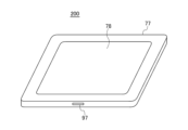
- FIG. 9 is a perspective view of an input device according to a second embodiment of the invention.
- This input device 200 has a main body 77 and a screen section 78.
- the input device 200 has the elements shown in FIG. 4 except for the pad operation section 50 and the setting operation section 90, plus a screen section 78.
- the pad operation section 50 and the setting operation section 90 are realized by being displayed on the screen section 78.
- the setting operation section 90 may be physically provided as in the first embodiment.
- illustration of the display section 96 is omitted, the display section 96 may also be realized by the screen section 78.
- the screen display control unit 74 (FIG. 6) includes a first group GrL including a plurality of pads (operators) and a plurality of pads arranged at symmetrical positions with respect to the plurality of pads included in the first group GrL.
- the second group GrR is displayed on the screen section 78 (on the screen). That is, a group of pads having the same layout as that shown in FIG. 3 is displayed on the screen section 78 in a touch-operable manner. Note that this process is executed, for example, in step S102 of FIG.
- the processing after step S103 is the same as that described in the first embodiment.
- the same effects as the first embodiment can be achieved with regard to facilitating the sound parameter setting operation.
- the input device may be provided with an output terminal, and sound information corresponding to input operations may be outputted from the output terminal to the outside.
- a sound generator (not shown) may be connected to the output terminal, and the sound generator may generate sound.
- the input device may be used to input performance information to be recorded by recording the input performance information in a memory (not shown) or outputting it to the outside. Furthermore, the input performance information may be reproduced or recorded on another device.
- the physical pad operating section 50 shown in the first embodiment or the virtual pad operating section 50 shown in the second embodiment is provided on the panel surface of an electronic musical instrument (electronic keyboard instrument, etc.). It's okay to be hit.
- the input device 100 may be installed in other electronic devices such as an electronic musical instrument (portable keyboard, etc.) or a MIDI keyboard.
- the keyboard itself may be used as the physical pad operation section 50.
- the definition is centered around the entire keyboard or a specific key range, at least the white keys can be said to be left-right symmetrical, so the present invention can be applied. In these cases, the electronic musical instrument becomes the input device of the present invention.
- the same effect as the present invention may be achieved by reading a storage medium storing a control program represented by software for achieving the present invention into the present input device, and in that case, the storage medium
- the program code itself read out realizes the novel function of the present invention, and the non-transitory computer-readable recording medium that stores the program code constitutes the present invention.
- the program code may be supplied via a transmission medium or the like, in which case the program code itself constitutes the present invention.
- the storage medium in these cases may be a floppy disk, a hard disk, an optical disk, a magneto-optical disk, a CD-ROM, a CD-R, a magnetic tape, a nonvolatile memory card, or the like.
- Non-transitory computer-readable recording media include volatile memory (for example, DRAM) inside a computer system that serves as a server or client when a program is transmitted via a network such as the Internet or a communication line such as a telephone line. (Dynamic Random Access Memory) that retains programs for a certain period of time is also included.
- volatile memory for example, DRAM
- DRAM Dynamic Random Access Memory
- GrL 1st group, GrR 2nd group, 50 Pad operation section 74 Screen display control section, 75 Instruction reception section, 76 Processing control section, 78 Screen section, 81 CPU, 90 Setting operation section, 92 Interlock mode enable/disable button , 93 Swap mode enable/disable button, 94 Swap execution button, 95 Confirm button, 100, 200 Input device
Landscapes
- Physics & Mathematics (AREA)
- Engineering & Computer Science (AREA)
- Acoustics & Sound (AREA)
- Multimedia (AREA)
- Electrophonic Musical Instruments (AREA)
Abstract
パッド操作部50は、複数のパッドを含む第1群GrLと、第1群GrLに含まれる複数のパッドに対して対称位置に配置された複数のパッドを含む第2群GrRとを含む。CPU81は、音パラメータの設定指示が受け付けられたことに応じて、互いに対称位置関係にあるパッドの組のうち少なくとも1つの組を設定対象として、音パラメータを設定する設定処理を実行する。設定処理として、設定対象の組において、第1群GrLのパッドに対する音パラメータの設定を第2群GrRのパッドにも反映させる連動処理、または、第1群GrLのパッドに設定されている音パラメータと第2群GrRのパッドに設定されている音パラメータとを入れ替える入れ替え処理が実行される。
Description
本発明は、入力装置およびその制御方法、プログラムに関する。
従来、複数の操作子に音パラメータを設定する入力装置が知られている。特許文献1の装置では、演奏情報を入力するための操作子(パッド)の各々に音パラメータが割り当てられている。
しかし、特許文献1では、音パラメータをどのように設定するかについて開示されていない。ユーザは、所望する操作子に所望する音パラメータを設定したい場合がある。各操作子に音パラメータを1つ1つ設定する操作は煩雑である。また、同じ装置を、右利きのユーザと左利きのユーザとで使い回したい場合もある。従って、音パラメータの設定操作を効率的に行うことができるようにすることが望ましい。
本発明の一つの目的は、音パラメータの設定操作を容易にすることができる入力装置を提供することである。
本発明の一形態によれば、複数の操作子を含む第1群と、前記第1群に含まれる複数の操作子に対して対称位置に配置された複数の操作子を含む第2群と、を含む操作受付部と、音パラメータの設定指示を受け付ける指示受付部と、前記設定指示が受け付けられたことに応じて、互いに対称位置関係にある操作子の組のうち少なくとも1つの組を設定対象として、音パラメータを設定する設定処理を実行する制御部と、を有し、前記制御部は、前記設定処理として、前記設定対象の組において、前記第1群の操作子に対する音パラメータの設定を前記第2群の操作子にも反映させる第1処理を実行するか、または、前記設定対象の組において、前記第1群の操作子に設定されている音パラメータと前記第2群の操作子に設定されている音パラメータとを入れ替える第2処理を実行する、入力装置が提供される。
本発明の一形態によれば、音パラメータの設定操作を容易にすることができる。
以下、図面を参照して本発明の実施の形態を説明する。
(第1の実施の形態)
図1は、本発明の第1の実施の形態に係る入力装置の平面図である。この入力装置100は、演奏操作の入力に適した入力装置であり、一例として電子楽器(電子打楽器)として構成される。入力装置100は、音パラメータを設定乃至入力するための装置である。
図1は、本発明の第1の実施の形態に係る入力装置の平面図である。この入力装置100は、演奏操作の入力に適した入力装置であり、一例として電子楽器(電子打楽器)として構成される。入力装置100は、音パラメータを設定乃至入力するための装置である。
入力装置100は筐体102を有する。筐体102の上面側にはパネル103が設けられている。パネル103には、パッド操作部50、設定操作部90、表示部96、スピーカ97が配置される。設定操作部90は、ユーザ101から音パラメータの設定指示(あるいは入力指示)などを受け付ける操作子を含む指示受付部である。設定操作部90は、メニューボタン91、連動モード有効/無効ボタン92(指定部)、入れ替えモード有効/無効ボタン93(指定部)、入れ替え実行ボタン94、決定ボタン95、増減ボタン98を含む。
パッド操作部50は、ユーザ101が演奏情報を入力するための複数の操作子(以下、パッドという)を含む操作受付部である。パッド操作部50に含まれる複数のパッドには、パッドK、H1~H3、C1、C2、S1、S2、R1、R2、M1、M2、T1~T6がある。
ユーザ101は、通常、図1に示すように、パッドKが手前側となる位置で入力装置100を使用する。以降、便宜上、ユーザ101から見て手前側を前側、奥側を後ろ側とし、左右方向についてもユーザ101から見た方向を基準とする。
パッドごとに形状は異なるが、基本構成は互いに共通である。各パッドは、入力操作(演奏操作)の対象となる入力エリアを構成する物理的なスイッチである。各パッドは、表面シートと、土台プレート(図示略)と、センサ(図示略)とを有する。土台プレートは、例えば、金属の板やプラスチックの板である。土台プレートの上にはセンサが配置されており、さらにその上には表面シートが配置されている。表面シートは、パッドの表面を構成する。パッドの表面は平らになっており、パネル103から露出している。ユーザ101は、通常、入力操作をする際、指でパッドを叩く。指への衝撃を和らげるために、表面シートには、例えばゴム板などが採用される。
上記センサは、ユーザ101による入力操作を検知する。上記センサは、パッド毎に設けられている。上記センサは、例えば対応するパッドへ加わる圧力の変化を検知する圧力センサなどである。上記センサは、圧力の変化に応じた振幅の信号を、入力操作を示す情報として出力する。なお、上記センサは、圧力センサに限らず、振動センサであってもよい。
一例として、各パッドは次のように構成される。下から順に、基板上の導電パターン、導電シート、ゴムシートが配置される。導電シートの下にはスペーサがあり、ゴムシートが乗った状態でも導電パターンと導電シートは導通しないか、もしくはごく僅かに導通する。ゴムシートを指で叩く(または押し込む)などによって上から圧力を加えると、導電シートが押されて導電パターンと接触し、その接触面積に応じて電圧値が変化する。上記センサが電圧値を検出することで、指で叩いた(または押し込んだ)強さなどを検出することができる。
各パッドには、電子音の音色、例えばドラム(パーカッションを含んでもよい)の音色が割り当てられて(アサインされて)いる。割り当てられる電子音の音色は問わない。ユーザ101がパッドを入力操作すると、そのパッドに対応付けられた音色の音がスピーカ97から発せられる。後述するように、各パッドに割り当てる音色は変更可能である。なお、一部のパッドについては割り当てられている音色が不変(固定)であってもよい。
図2は、パッド操作部50の平面図である。
図2に示すように、パッド操作部50は、第1領域10と、第2領域20と、第3領域30と、第4領域40とを有する。第1、第2、第3、第4領域の並び方向が前後方向である。当該並び方向に直交する方向が左右方向である。第1領域10から遠ざかる方向(後方)に、順番に第1領域10、第4領域40、第2領域20、第3領域30が配置されている。第1領域10と第3領域30との間に第4領域40がある。第1領域10、第2領域20、第3領域30の形状は互いに異なる。第1領域10と第2領域20とは前後方向に隣り合っている。
第1領域10は、主としてバスドラムの音色が割り当てられた1以上のパッドを含み、一例としてパッドK、M1、M2を含む。第2領域20は、主としてスネアドラムの音色が割り当てられた1以上のパッドを含み、一例としてパッドS1、R1、R2を含む。第3領域30は、主としてシンバルの音色が割り当てられた1以上のパッドを含み、一例としてパッドH1~H3、C1、C2を含む。第4領域40は、主としてタム(Tom)の音色が割り当てられた1以上のパッドを含み、一例としてパッドS2、T1~T6を含む。
パッドK、S2、S1、H2の重心をそれぞれ、G10、G40、G20、G30とする。上方から見て、G10、G40、G20、G30を通る仮想直線をP0とする。仮想直線P0は、左右方向におけるパッド操作部50の中央線でもある。仮想直線P0は、左右方向における第1領域10、第2領域20、第3領域30、第4領域40の各々の中央線でもある。入力装置100は、右利き、左利きのいずれの利き手でも操作されることを想定し、且つ、両手で操作されることも想定している。そのため、パッド全体は、仮想直線P0を中心とする左右線対称にレイアウトされている。
まず、パッドK、S2、S1、H2は左右方向における中央に配置されている。パッドT1、T2、T3とパッドT6、T5、T4とは、それぞれ、仮想直線P0に対して(仮想直線P0を中心として)線対称である。パッドM1、R1、C1とパッドM2、R2、C2とは仮想直線P0に対して線対称である。パッドH1とパッドH3とは仮想直線P0に対して線対称である。
上方から見て、第1領域10と第4領域40との境界線51、第2領域20と第3領域30との境界線53、第4領域40と第2領域20との境界線52はいずれも、手前側に凸となっている曲線である。また、上方から見て、左右方向に隣り合うパッド同士の対向する端面は、直線で且つ、後方ほど仮想直線P0に近くなるように傾斜している。このような端面の傾斜や境界線の湾曲によって、無理のない自然な姿勢での演奏入力が容易となる。
パッドS1には、上方へ突出した凸部61、62が設けられている。ユーザは、凸部61、62のいずれかに接触することで、視覚によらずにパッドS1の位置を認識することができる。
図3は、パッド操作部50の平面図である。互いに対称位置関係にある一対の操作子(パッド)を「組」と呼ぶ。左側のパッド群が第1群GrLで、右側のパッド群が第2群GrRである。第1群GrLには、パッドT1、T2、T3、M1、R1、C1、H1が含まれる。第2群GrRには、パッドT6、T5、T4、M2、R2、C2、H3が含まれる。
図4は、入力装置100のブロック図である。パッド操作部50における各パッドの操作により生成された演奏情報や、設定操作部90における各操作子の操作により生成された操作情報は、バス80を介してCPU81に送られる。表示部96はLCD等で構成され、CPU81からの指示に従って各種情報を表示する。このほか、CPU81には、バス80を介して、発音部79、ROM82、RAM83、タイマ84、記憶部85、各種I/F(インターフェイス)86が接続される。
CPU81は、本装置全体を制御する。ROM82は、CPU81が実行する制御プログラムや各種データを記憶している。RAM83は、CPU81が制御プログラムを実行する際のワークエリアを提供する。記憶部85は、不揮発メモリを含み、各種情報を記憶する。各種I/F86は、有線または無線の通信I/Fのほか、MIDI(Musical Instrument Digital Interface)を含んでもよい。発音部79は、スピーカ97(図1)のほか音源回路や効果回路を含み(図示せず)、各パッドの操作により生成された演奏情報に基づく音を発生させる。
本実施の形態では、音パラメータの設定モードとして「連動モード」と「入れ替えモード」とがある。これらの設定モードは、互いに対称位置関係にあるパッドの組に適用される。設定モードが適用される組を「設定対象の組」と呼ぶ。
連動モードは、設定対象の組において、第1群GrL(または第2群GrR)のパッドに対する音パラメータの設定を、当該パッドとは対称位置に配置された第2群GrR(または第1群GrL)のパッドにも反映させる連動処理(第1処理)を実行するモードである。入れ替えモードは、設定対象の組において、第1群GrLのパッドに設定されている音パラメータと、当該パッドとは対称位置に配置された第2群GrRのパッドに設定されている音パラメータとを入れ替える入れ替え処理(第2処理)を実行するモードである。
これら2つの設定モードは、排他的に設定されるのではなく、個々に有効/無効の設定が可能で、併存することができる。連動モードの有効/無効は、連動モード有効/無効ボタン92に対するユーザ操作により指定でき、入れ替えモードの有効/無効は、入れ替えモード有効/無効ボタン93に対するユーザ操作により指定できる。
連動モードにおいては、ユーザは、設定する音パラメータの候補を入力した状態で、決定ボタン95を押すことで、連動処理の実行を指示することができる。例えば、パッドH1とパッドH3とが設定対象の組で、且つ、連動モードが有効である場合に、パッドH1に第1の音パラメータがアサインされると、自動的にパッドH3にも第1の音パラメータがアサインされる。この逆も成り立つ。
一方、パッドC1とパッドC2とが設定対象の組で、且つ、入れ替えモードが有効であるとする。パッドC1に第1の音パラメータがアサインされ、パッドC2に第2の音パラメータがアサインされている状態で、入れ替えの実行が指示されると、パッドC1に第2の音パラメータがアサインされ、パッドC2に第1の音パラメータがアサインされる。つまり、パッドC1、C2間で、アサインされている音パラメータが入れ替わる。
図5は、「設定対象となり得る組」を設定する際の表示部96の表示例を示す図である。設定対象となり得る組は、メニューボタン91、増減ボタン98、決定ボタン95等へのユーザ操作により設定される。ユーザは、「アサイン一致」にマークを付けることで、設定対象となり得る組を設定することができる。例えば、図5の例では、パッドH1、H3、パッドT1、T6、パッドT2、T5、パッドC1、C2が、設定対象となり得る組に設定されている。なお、「設定対象となり得る組」は、連動モードと入れ替えモードとで個別に設定できるようにしてもよい。
なお、設定対象となり得る組の設定方法はこの手法に限定されず、画面表示を用いることも必須でない。また、ユーザ操作によらず、固定的に、全パッドまたは一部のパッドを設定対象となり得る組として扱ってもよい。
なお、連動モードにおいて、連動する方向は両方向でなく片方向であってもよい。例えば片方向の場合、パッドH1に第1の音パラメータがアサインされると、自動的にパッドH3にも第1の音パラメータがアサインされるが、パッドH3に第2の音パラメータがアサインされても、パッドH1にアサインされた音パラメータは変更されない。連動する方向を両方向とするか片方向とするかは、予め決められていてもよいし、ユーザ操作により設定できるようにしてもよい。また、連動モードにおいて、設定指示の受け付け前の時点で互いに異なる音パラメータが設定されている組は、設定対象の組から除外されるようにしてもよい。
入れ替えモードでは、設定対象となり得る組の全てが設定対象の組となる。一方、連動モードでは、設定対象となり得る組のうち最後に打撃された(叩かれた)パッドとそれの対称関係にあるパッドとの組が、設定対象の組となる。なお、連動モードにおける設定対象の組を決める手法はこの例に限定されない。すなわち、複数のパッドの中から1つのパッドが選択されている状態を実現できれば他の手法を採用してもよい。例えば、ユーザが所望するパッドを閾値以上の強さで叩く、あるいは、ユーザがUIを用いて所望するパッドを選択する、等が考えられる。
連動モードでの連動処理は、例えば、ユーザが音パラメータを設定(設定変更を含む)する操作をすると実行される。すなわち、連動モードでは、設定指示として、設定対象の組のいずれかのパッドに対する音パラメータの設定指示が受け付けられた場合に、設定処理として連動処理が実行される。音パラメータの設定指示は、メニューボタン91、増減ボタン98、決定ボタン95等へのユーザ操作があることで受け付けられる。
入れ替えモードでは、設定指示として、音パラメータの入れ替えを実行する指示が受け付けられた場合に、設定処理として入れ替え処理が実行される。例えば、入れ替え実行ボタン94が押されることで音パラメータの入れ替えを実行する指示が受け付けられる。
1つのパッドに対して1度に設定できる音パラメータは1つ以上であり、2つ以上の音パラメータを一括して設定することもできる。例えば、音パラメータには、主に音色に依存するもの(ボイス:Voice)として、「Category」、「Number」、「Volume」、「Pan」、「Tuning」、「Decay」、「Cutoff」、「Resonance」、「Reverb Send」、「Chorus Send」等がある。このほか、音パラメータには、主に音色に依存しないもの(Pad)として、「Choke」、「Link」、「Velocity Limit Low」、「Velocity Limit High」、「Note Repeat」等がある。このほか、音パラメータには、主にMIDIとパッドの演奏感に関するもの(Trigger)として、「MIDI Channel」、「MIDI Note Number」、「Velocity Curve」、「Velocity Fixed Value」、「Velocity Minimum」、「Velocity Maximum」、「After Touch Curve」、「After Touch Fixed Value」、「After Touch Minimum」、「After Touch Maximum」等がある。
図6は、音パラメータ設定処理を実現する機能ブロックを示す図である。この機能ブロックには、画面表示制御部74、指示受付部75、処理制御部76が含まれる。画面表示制御部74、指示受付部75、処理制御部76の各機能は、CPU81、ROM82、RAM83、タイマ84、記憶部85等の協働により実現される。なお、本実施の形態では画面表示制御部74は必須でなく、画面表示制御部74は第2の実施の形態で説明される。
指示受付部75は、音パラメータの設定を指示する設定指示を受け付ける。例えば指示受付部75は、メニューボタン91、増減ボタン98、決定ボタン95等へのユーザ操作を設定指示として受け付ける。処理制御部76は、設定指示が受け付けられたことに応じて、設定対象の組に対して音パラメータを設定する設定処理を実行する。処理制御部76は、連動モードにおいては上記連動処理(第1処理)を実行し、入れ替えモードにおいては上記入れ替え処理(第2処理)を実行する。
図7は、音パラメータ設定処理を示すフローチャートである。この処理は、ROM82に格納されたプログラムをCPU81がRAM83に展開して実行することにより実現される。この処理は、入力装置100の主電源がオンにされると開始される。あるいは、この処理は、音パラメータの設定開始の指示が設定操作部90により受け付けられると開始されてもよい。
ステップS101では、CPU81は初期化を行う。例えばCPU81は、各パッドへの音パラメータの設定を前回の設定状態にする。また、CPU81は、音パラメータの設定モードをデフォルト設定にし、例えば、連動モード、入れ替えモードをいずれも有効にする。
ステップS102では、CPU81は、その他の処理を実行する。例えば、CPU81は、ユーザ操作や一定の時間経過に応じて、音パラメータ設定処理を終了させる等の処理を実行する。あるいは、CPU81は、連動処理や入れ替え処理に該当しない、パッド単独でのアサイン処理を実行してもよい。
ステップS103では、CPU81は、パッドに対する打撃、すなわち演奏入力があったか否かを判別する。そしてCPU81は、演奏入力があった場合は、ステップS111で、打撃されたパッドにアサインされている音パラメータに基づいて演奏処理を実行する。例えばスネアドラムの音色がアサインされているパッドS1が打撃されたなら、CPU81は、スネアドラムの音色であって、設定されているVolumeやPan等の値に応じた音を、発音部79から発音させる。
CPU81は、ステップS103で演奏入力がない場合はステップS104に進み、また、ステップS111の後はステップS104に進む。ステップS104では、CPU81は、音パラメータ設定に関する操作があったか否かを判別する。ここでの操作には、設定モード(連動モード、入れ替えモード)を設定する操作、設定対象となり得る組の設定する操作が含まれるが、音パラメータの設定指示は含まれない。また、連動モードにおける設定する音パラメータの候補の入力操作等も含まれる。ユーザは、設定操作部90を操作することで、設定する音パラメータの候補を随時変更可能である。
音パラメータ設定に関する操作があった場合は、CPU81は、ステップS112で、当該操作に対応する処理を実行し、ステップS105に進む。CPU81は、音パラメータ設定に関する操作がない場合は、ステップS105に進む。
ステップS105では、CPU81は、入れ替えモードが「有効」に設定されているか否かを判別する。CPU81は、入れ替えモードが「有効」に設定されていない場合はステップS106に進み、入れ替えモードが「有効」に設定されている場合は、ステップS113に進む。
ステップS113では、CPU81は、入れ替え処理の実行指示(設定指示)があったか否かを判別する。上述したように、入れ替え実行ボタン94が押された場合に、入れ替え処理の実行指示があったと判別される。CPU81は、入れ替え処理の実行指示がない場合はステップS106に進み、入れ替え処理の実行指示があった場合は、ステップS114に進む。なお、仮に、入れ替えモードが「無効」に設定されている場合に入れ替え実行ボタン94が押されたとしても、入れ替え処理の実行指示として受け付けられない。
なお、入力装置100は、いずれの利き手でも操作されることを想定しているので、入れ替え処理は、実質的に右利き用と左利き用とに切り替えることとみなすこともできる。この観点からは、入れ替え処理の実行指示を、利き手の切り替え実行指示と解釈してもよい。
ステップS114では、CPU81は、入れ替え処理を実行する。すなわちCPU81は、設定対象の組の各々において、第1群GrLのパッドと第2群GrRのパッドとで、設定されている音パラメータを入れ替える。例えば、パッドC1、C2にそれぞれ第1、第2のクラッシュシンバルの音色がアサインされていた場合、入れ替え処理により、パッドC1に第2のクラッシュシンバルの音色がアサインされ、パッドC2に第1のクラッシュシンバルの音色がアサインされる。あるいは、設定対象となり得る組が図5に示す設定状態であるとすると、第1群GrL、第2群GrRのうち、パッドH1、T1、T2、T3と、パッドH3、T6、T5、T4とで、アサインされる音パラメータが入れ替わる。ステップS114の処理は、例えば、「左利き向け」と「右利き向け」とを切り替えるのに有効である。ステップS114の後、CPU81は、ステップS106に進む。
ステップS106では、CPU81は、連動モードが「有効」に設定されているか否かを判別する。そしてCPU81は、連動モードが「有効」に設定されていない場合はステップS102に戻り、連動モードが「有効」に設定されている場合はステップS107に進む。
ステップS107では、CPU81は、設定対象の組を特定する。上述のように、CPU81は、設定対象となり得る組のうち最後に(直前に)打撃されたパッドが属する組を、設定対象の組として特定する。なお、初回使用時のように、最後に打撃されたパッドが記憶されていない場合は、CPU81は、デフォルトのパッドの組を設定対象の組と特定してもよい。なお、通常、ユーザは、連動処理を適用したい組のいずれかのパッドを1回以上叩いてから、連動処理のための操作へ移行すればよい。
ステップS108では、CPU81は、設定する音パラメータの候補が入力済みか否かを判別する。この候補はステップS112で入力される。そしてCPU81は、音パラメータの候補が入力済みでない場合はステップS102に戻り、音パラメータの候補が入力済みである場合はステップS109に進む。
ステップS109では、CPU81は、連動モードにおいて設定する音パラメータを決定する操作(設定指示)が受け付けられたか否かを判別する。ここでは、決定ボタン95が押されたか否かが判別される。そしてCPU81は、設定する音パラメータを決定する操作が受け付けられていない場合はステップS102に戻り、設定する音パラメータを決定する操作が受け付けられた場合は、ステップS110に進む。
ステップS110では、CPU81は、設定対象の組に対して、連動処理により音パラメータを設定する。例えば、パッドT1に、タム音色のうち「Maple Floor Tom」という候補が入力された状態で決定ボタン95が押されたとすると、パッドT1、T6の双方に「Maple Floor Tom」がアサインされる。この処理は、例えば、「左利き向け」と「右利き向け」の両方に適したアサイン状態を維持するのに有効である。その後、CPU81は、ステップS102に戻る。
なお、互いに異なる音パラメータが設定されている組を設定対象の組から除外するよう設定されていた場合は、ステップS107において次のように処理される。すなわち、最後に打撃されたパッドが属する組のパッドに、互いに異なる音パラメータが設定されていた場合は、CPU81は、設定対象の組が存在しないと判定し、ステップS108に進む。その後、S108→S109→S110と推移した場合、ステップS110では、CPU81は、音パラメータの候補を、最後に打撃されたパッドに対して単独で設定する。
なお、連動する方向が片方向であると設定されていた場合は、ステップS107において次のように処理される。例えば、第1群GrLでのアサインを第2群GrRにも反映させるが、第2群GrRでのアサインを第1群GrLに反映させないという片方向設定がされていた場合を例にとる。CPU81は、最後に打撃されたパッドが第1群GrLに属する場合は、通常通り、最後に打撃されたパッドが属する組を、設定対象の組として特定する。
しかし、最後に打撃されたパッドが第2群GrRに属する場合は、ステップS107において、CPU81は、設定対象の組が存在しないと判定し、ステップS108に進む。その後、S108→S109→S110と推移した場合、ステップS110では、CPU81は、音パラメータの候補を、最後に打撃されたパッドに対して単独で設定する。
本実施の形態によれば、パッド操作部50は、複数のパッドを含む第1群GrLと、第1群GrLに含まれる複数のパッドに対して対称位置に配置された複数のパッドを含む第2群GrRとを含む。互いに対称位置関係にあるパッド(操作子)の組のうち少なくとも1つの組が設定対象の組となる。制御部としてのCPU81は、音パラメータの設定指示が受け付けられたことに応じて、設定対象の組に対して音パラメータを設定する設定処理を実行する。
CPU81は、設定指示として、設定対象の組のいずれかのパッドに対する音パラメータの設定指示が受け付けられた場合に、設定処理として連動処理(第1処理)を実行する。連動処理では、CPU81は、設定対象の組において、第1群GrL(または第2群GrR)のパッドに対する音パラメータの設定を第2群GrR(または第1群GrL)のパッドにも反映させる。CPU81は、設定指示として、音パラメータの入れ替えを実行する指示が受け付けられた場合に、設定処理として入れ替え処理(第2処理)を実行する。入れ替え処理では、CPU81は、設定対象の組において、第1群GrLのパッドに設定されている音パラメータと第2群GrRのパッドに設定されている音パラメータとを入れ替える。これらの処理により、音パラメータの設定操作を容易にすることができる。
例えば、フィンガードラマーは典型的なパッドアサインを簡単に作り込むことができる。また、1つの入力装置100を利き手が異なる複数のユーザ間で簡単に使い回すことができる。従って、フィンガードラマーは利き手を問わずに同じ演奏感を得ることができる。簡単な操作により、複数のパッドのアサインを変更することも可能である。
また、互いに異なる音パラメータが設定されている組を設定対象の組から除外することで、連動設定する意図がないと考えられるパッドの連動設定を回避し、使い勝手を向上させることができる。
また、連動モード、入れ替えモードのそれぞれの有効/無効を指定できる。また、設定対象の組は、ユーザ操作に応じて決定できる。さらに、連動モードにおいて、連動する方向を両方向とするか片方向とするかを指定できる。従って、使い勝手を向上させることができる。
また、設定処理を実行する際、1つのパッドに対して2つ以上の音パラメータを一括して設定可能であるので、設定作業を簡単にすることができる。
なお、本実施の形態において、連動モードにおいても、複数の組を設定対象の組として指定できるようにし、且つ、アサイン状態を第1群GrLまたは第2群GrRのいずれかに揃える(統一する乃至一致させる)ようにしてもよい。この場合、音パラメータの候補の入力は必要でなく、ステップS108は廃止されてもよい。ステップS107以降では次のように処理される。
例えば、ステップS107では、CPU81は、図5に示す表示画面上で「アサイン一致」にマークを付けた「設定対象となり得る組」の全てを設定対象の組と特定する。さらにCPU81は、設定対象の組のうち最後に打撃されたパッドが属する群(上位側の群と称する)が第1群GrLまたは第2群GrRgのいずれであるかを特定する。次に、ステップS109で、決定ボタン95が押されることで設定指示があると、CPU81は、ステップS110で、全ての設定対象の組において、上位側の群の各パッドのアサイン状態を、当該各パッドと対称位置関係にある各パッドに反映させる。つまりCPU81は、上位側でない群の音パラメータのアサイン設定を、上位側の群の音パラメータのアサイン設定と同じ状態にする。この処理は、例えば、「左利き向け」と「右利き向け」の両方に適したアサイン状態にするのに有効である。
なお、連動モード、入れ替えモードの有効/無効を指定できることは必須でなく、常に両モードを有効としてもよい。
このほか、各モードの有効/無効に関し、次のように構成してもよい。まず、各モードの有効/無効はパッド単位で設定できるようにしてもよい。各モードの実行時に有効/無効を選択できるようにしてもよい。いずれか片方のモードが常に有効であってもよい。連動モードと入れ替えモードとは排他的に有効となるようにしてもよい。他の設定と連動して各モードの有効/無効が切り替わるようにしてもよい。他の設定を参照して(他の設定に応じて)各モードの有効/無効が切り替わるようにしてもよい。変更された音パラメータの種類によって各モードの有効/無効が切り替わるようにしてもよい。
なお、設定処理の実行直前の設定状態を記憶しておき、所定の操作により復元できるようにしてもよい。
なお、境界線51、53、52はいずれも手前側に凸となっている曲線であった。しかしこれは必須でなく、境界線51、53、52はいずれも左右方向に平行な直線であってもよい。
なお、第1群GrLに含まれる複数のパッドと第2群GrRに含まれる複数のパッドとが対称位置にある装置に本発明は適用される。ここで、「対称」は、左右対称に限らず、また、線対称に限らない。従って、上下対称や点対称も含まれる。
例えば、図8に変形例を示すように、点対称のパッドを有する装置であってもよい。図8に示す例では、1つの筐体に、同じパッドレイアウトの第1のパッド操作部50-Aと第2のパッド操作部50-Bとが、点P1を基準に点対称に配置されている。
第1のパッド操作部50-Aが第1群GrLに相当し、第2のパッド操作部50-Bが第2群GrRに相当すると考えることができる。この例であれば、全てのパッドが、点P1を中心として互いに点対称の関係にあるパッドを有する。従って、第1のパッド操作部50-AのパッドK、S1、S2、H2と第2のパッド操作部50-BのパッドK、S1、S2、H2とも点対称の関係にある。
(第2の実施の形態)
第1の実施の形態では、パッドは物理的なスイッチであった。しかし、仮想的なパッドであっても本発明を適用可能である。
第1の実施の形態では、パッドは物理的なスイッチであった。しかし、仮想的なパッドであっても本発明を適用可能である。
図9は、本発明の第2の実施の形態に係る入力装置の斜視図である。この入力装置200は、本体77と画面部78とを有する。入力装置200は、図4に示す要素のうちパッド操作部50および設定操作部90を除いたものに、画面部78を加えたものである。パッド操作部50および設定操作部90は、画面部78に表示されることで実現される。なお、設定操作部90を、第1の実施の形態と同様に物理的に備えてもよい。また、表示部96の図示は省略されているが、表示部96も画面部78によって実現されてもよい。
画面表示制御部74(図6)は、複数のパッド(操作子)を含む第1群GrLと、第1群GrLに含まれる複数のパッドに対して対称位置に配置された複数のパッドを含む第2群GrRとを画面部78に(画面上に)表示させる。つまり、画面部78には、図3に示すものと同じレイアウトのパッド群が、タッチ操作可能に表示される。なお、この処理は、例えば、図7のステップS102で実行される。ステップS103以降の処理は、第1の実施の形態で説明したのと同様である。
本実施の形態によれば、音パラメータの設定操作を容易にすることに関し、第1の実施の形態と同様の効果を奏することができる。
なお、第1~第4領域の全てを設けることは必須でなく、例示したパッドの全てを備えることも必須でない。
なお、入力装置は電子楽器として構成されることは必須でなく、また、発音機能を有することも必須でない。従ってスピーカ97を設けることは必須でない。例えば、入力装置に出力端子を設け、入力操作に応じた音情報を出力端子から外部へ出力してもよい。例えば、出力端子に不図示の音発生装置を接続し、音発生装置から音を発生させてもよい。また、入力された演奏情報を不図示のメモリに記録するか、外部に出力することで、入力装置を、記録すべき演奏情報の入力のために用いてもよい。また、入力された演奏情報を、他の装置で再生または記録してもよい。
なお、第1の実施の形態で示した物理的なパッド操作部50または第2の実施の形態で示した仮想的なパッド操作部は、電子楽器(電子鍵盤楽器等)のパネル面等に設けられてもよい。また、電子楽器(ポータブルキーボード等)やMIDIキーボード等、他の電子機器に本入力装置100を搭載してもよい。あるいは、電子鍵盤楽器においては鍵盤自体を物理的なパッド操作部50として利用してもよい。例えば鍵盤全体または特定の鍵域を中心に定義すれば、少なくとも白鍵は左右対称と言えるので、本発明を適用することが可能である。これらの場合、当該電子楽器が、本発明の入力装置となる。
以上、本発明をその好適な実施形態に基づいて詳述してきたが、本発明はこれら特定の実施形態に限られるものではなく、この発明の要旨を逸脱しない範囲の様々な形態も本発明に含まれる。上述の実施形態の一部を適宜組み合わせてもよい。
なお、本発明を達成するためのソフトウェアによって表される制御プログラムを記憶した記憶媒体を、本入力装置に読み出すことによって、本発明と同様の効果を奏するようにしてもよく、その場合、記憶媒体から読み出されたプログラムコード自体が本発明の新規な機能を実現することになり、そのプログラムコードを記憶した、非一過性のコンピュータ読み取り可能な記録媒体は本発明を構成することになる。また、プログラムコードを伝送媒体等を介して供給してもよく、その場合は、プログラムコード自体が本発明を構成することになる。なお、これらの場合の記憶媒体としては、ROMのほか、フロッピディスク、ハードディスク、光ディスク、光磁気ディスク、CD-ROM、CD-R、磁気テープ、不揮発性のメモリカード等を用いることができる。非一過性のコンピュータ読み取り可能な記録媒体としては、インターネット等のネットワークや電話回線等の通信回線を介してプログラムが送信された場合のサーバやクライアントとなるコンピュータシステム内部の揮発性メモリ(例えばDRAM(Dynamic Random Access Memory))のように、一定時間プログラムを保持しているものも含む。
GrL 第1群、 GrR 第2群、 50 パッド操作部、 74 画面表示制御部、 75 指示受付部、 76 処理制御部、 78 画面部、 81 CPU、 90 設定操作部、 92 連動モード有効/無効ボタン、 93 入れ替えモード有効/無効ボタン、 94 入れ替え実行ボタン、 95 決定ボタン、 100、200 入力装置
Claims (16)
- 複数の操作子を含む第1群と、前記第1群に含まれる複数の操作子に対して対称位置に配置された複数の操作子を含む第2群と、を含む操作受付部と、
音パラメータの設定指示を受け付ける指示受付部と、
前記設定指示が受け付けられたことに応じて、互いに対称位置関係にある操作子の組のうち少なくとも1つの組を設定対象として、音パラメータを設定する設定処理を実行する制御部と、を有し、
前記制御部は、前記設定処理として、前記設定対象の組において、前記第1群の操作子に対する音パラメータの設定を前記第2群の操作子にも反映させる第1処理を実行するか、または、前記設定対象の組において、前記第1群の操作子に設定されている音パラメータと前記第2群の操作子に設定されている音パラメータとを入れ替える第2処理を実行する、入力装置。 - 前記制御部は、前記設定指示として、前記第1群の操作子に対する前記音パラメータの設定指示が受け付けられた場合は、前記設定処理として前記第1処理を実行する、請求項1に記載の入力装置。
- 前記制御部は、前記第2群の操作子に対する前記音パラメータの設定指示が受け付けられた場合は、前記設定対象の組において、前記第2群の操作子に対する前記音パラメータの設定を前記第1群の操作子にも反映させる、請求項2に記載の入力装置。
- 前記設定指示の受け付け前の時点で互いに異なる音パラメータが設定されている組は、前記設定対象の組から除外される、請求項2または3に記載の入力装置。
- 前記第1処理の有効/無効を指定する指定部を有し、
前記制御部は、前記第1処理が有効であることを条件に前記第1処理を実行する、請求項1乃至4のいずれか1項に記載の入力装置。 - 前記制御部は、前記設定指示として、音パラメータの入れ替えを実行する指示が受け付けられた場合は、前記設定処理として前記第2処理を実行する、請求項1に記載の入力装置。
- 前記第2処理の有効/無効を指定する指定部を有し、
前記指示受付部は、前記第2処理が有効な場合にのみ、音パラメータの入れ替えを実行する前記指示を前記設定指示として受け付ける、請求項6に記載の入力装置。 - 前記制御部は、前記設定処理を実行する際、1つの前記操作子に対して2つ以上の音パラメータを一括して設定可能である、請求項1乃至7のいずれか1項に記載の入力装置。
- 前記設定対象の組は、予め決まっている、請求項1乃至8のいずれか1項に記載の入力装置。
- 前記設定対象の組は、ユーザ操作に応じて決定される、請求項1乃至8のいずれか1項に記載の入力装置。
- 前記対称位置は、線対称の位置である、請求項1乃至10のいずれか1項に記載の入力装置。
- 前記音パラメータには、少なくともボイスが含まれる、請求項1乃至11のいずれか1項に記載の入力装置。
- コンピュータにより実現される入力装置の制御方法であって、
音パラメータの設定を指示する設定指示を受け付け、
前記設定指示が受け付けられたことに応じて、複数の操作子を含む第1群と、前記第1群に含まれる複数の操作子に対して対称位置に配置された複数の操作子を含む第2群とにおいて、互いに対称位置関係にある操作子の組のうち少なくとも1つの組を設定対象として、音パラメータを設定する設定処理を実行し、
前記設定処理を実行する際には、前記設定対象の組において、前記第1群の操作子に対する音パラメータの設定を前記第2群の操作子にも反映させる第1処理を実行するか、または、前記設定対象の組において、前記第1群の操作子に設定されている音パラメータと前記第2群の操作子に設定されている音パラメータとを入れ替える第2処理を実行する、入力装置の制御方法。 - コンピュータにより実現される入力装置の制御方法であって、
複数の操作子を含む第1群と、前記第1群に含まれる複数の操作子に対して対称位置に配置された複数の操作子を含む第2群とを画面上に表示させ、
音パラメータの設定を指示する設定指示を受け付け、
前記設定指示が受け付けられたことに応じて、互いに対称位置関係にある操作子の組のうち少なくとも1つの組を設定対象として、音パラメータを設定する設定処理を実行し、
前記設定処理を実行する際には、前記設定対象の組において、前記第1群の操作子に対する音パラメータの設定を前記第2群の操作子にも反映させる第1処理を実行するか、または、前記設定対象の組において、前記第1群の操作子に設定されている音パラメータと前記第2群の操作子に設定されている音パラメータとを入れ替える第2処理を実行する、入力装置の制御方法。 - 入力装置の制御方法をコンピュータに実行させるプログラムであって、
前記入力装置の制御方法は、
音パラメータの設定を指示する設定指示を受け付け、
前記設定指示が受け付けられたことに応じて、複数の操作子を含む第1群と、前記第1群に含まれる複数の操作子に対して対称位置に配置された複数の操作子を含む第2群とにおいて、互いに対称位置関係にある操作子の組のうち少なくとも1つの組を設定対象として、音パラメータを設定する設定処理を実行し、
前記設定処理を実行する際には、前記設定対象の組において、前記第1群の操作子に対する音パラメータの設定を前記第2群の操作子にも反映させる第1処理を実行するか、または、前記設定対象の組において、前記第1群の操作子に設定されている音パラメータと前記第2群の操作子に設定されている音パラメータとを入れ替える第2処理を実行する、プログラム。 - 入力装置の制御方法をコンピュータに実行させるプログラムであって、
前記入力装置の制御方法は、
複数の操作子を含む第1群と、前記第1群に含まれる複数の操作子に対して対称位置に配置された複数の操作子を含む第2群とを画面上に表示させ、
音パラメータの設定を指示する設定指示を受け付け、
前記設定指示が受け付けられたことに応じて、互いに対称位置関係にある操作子の組のうち少なくとも1つの組を設定対象として、音パラメータを設定する設定処理を実行し、
前記設定処理を実行する際には、前記設定対象の組において、前記第1群の操作子に対する音パラメータの設定を前記第2群の操作子にも反映させる第1処理を実行するか、または、前記設定対象の組において、前記第1群の操作子に設定されている音パラメータと前記第2群の操作子に設定されている音パラメータとを入れ替える第2処理を実行する、プログラム。
Priority Applications (2)
| Application Number | Priority Date | Filing Date | Title |
|---|---|---|---|
| CN202280094069.8A CN118922882A (zh) | 2022-03-25 | 2022-12-27 | 输入装置及其控制方法、程序 |
| US18/895,869 US20250014544A1 (en) | 2022-03-25 | 2024-09-25 | Input device, control method of the same, and non-transitory computer-readable storage medium |
Applications Claiming Priority (2)
| Application Number | Priority Date | Filing Date | Title |
|---|---|---|---|
| JP2022-049447 | 2022-03-25 | ||
| JP2022049447A JP7835076B2 (ja) | 2022-03-25 | 2022-03-25 | 入力装置およびその制御方法、プログラム |
Related Child Applications (1)
| Application Number | Title | Priority Date | Filing Date |
|---|---|---|---|
| US18/895,869 Continuation US20250014544A1 (en) | 2022-03-25 | 2024-09-25 | Input device, control method of the same, and non-transitory computer-readable storage medium |
Publications (1)
| Publication Number | Publication Date |
|---|---|
| WO2023181574A1 true WO2023181574A1 (ja) | 2023-09-28 |
Family
ID=88100913
Family Applications (1)
| Application Number | Title | Priority Date | Filing Date |
|---|---|---|---|
| PCT/JP2022/048240 Ceased WO2023181574A1 (ja) | 2022-03-25 | 2022-12-27 | 入力装置およびその制御方法、プログラム |
Country Status (4)
| Country | Link |
|---|---|
| US (1) | US20250014544A1 (ja) |
| JP (1) | JP7835076B2 (ja) |
| CN (1) | CN118922882A (ja) |
| WO (1) | WO2023181574A1 (ja) |
Citations (4)
| Publication number | Priority date | Publication date | Assignee | Title |
|---|---|---|---|---|
| JP2005252542A (ja) * | 2004-03-03 | 2005-09-15 | Yamaha Corp | 音響信号処理装置の制御用プログラム |
| JP2010066659A (ja) * | 2008-09-12 | 2010-03-25 | Yamaha Corp | 電子打楽器 |
| JP2010256408A (ja) * | 2009-04-21 | 2010-11-11 | Yamaha Corp | 電子打楽器 |
| JP2021060572A (ja) * | 2019-10-04 | 2021-04-15 | 国立大学法人大阪大学 | 楽音入力装置、操作子の配置方法、楽譜の作成方法、楽譜、楽譜教示装置、入力装置、楽音入力方法、楽譜教示方法、及び入力方法 |
-
2022
- 2022-03-25 JP JP2022049447A patent/JP7835076B2/ja active Active
- 2022-12-27 CN CN202280094069.8A patent/CN118922882A/zh active Pending
- 2022-12-27 WO PCT/JP2022/048240 patent/WO2023181574A1/ja not_active Ceased
-
2024
- 2024-09-25 US US18/895,869 patent/US20250014544A1/en active Pending
Patent Citations (4)
| Publication number | Priority date | Publication date | Assignee | Title |
|---|---|---|---|---|
| JP2005252542A (ja) * | 2004-03-03 | 2005-09-15 | Yamaha Corp | 音響信号処理装置の制御用プログラム |
| JP2010066659A (ja) * | 2008-09-12 | 2010-03-25 | Yamaha Corp | 電子打楽器 |
| JP2010256408A (ja) * | 2009-04-21 | 2010-11-11 | Yamaha Corp | 電子打楽器 |
| JP2021060572A (ja) * | 2019-10-04 | 2021-04-15 | 国立大学法人大阪大学 | 楽音入力装置、操作子の配置方法、楽譜の作成方法、楽譜、楽譜教示装置、入力装置、楽音入力方法、楽譜教示方法、及び入力方法 |
Also Published As
| Publication number | Publication date |
|---|---|
| CN118922882A (zh) | 2024-11-08 |
| JP2023142499A (ja) | 2023-10-05 |
| US20250014544A1 (en) | 2025-01-09 |
| JP7835076B2 (ja) | 2026-03-25 |
Similar Documents
| Publication | Publication Date | Title |
|---|---|---|
| JP5163383B2 (ja) | 電子打楽器 | |
| JP5428567B2 (ja) | 電子打楽器 | |
| KR900011493A (ko) | 의사-입체음향을 발생시키는 능력을 갖는 전자게임기구 | |
| JP7732534B2 (ja) | 電子楽器、電子楽器の制御方法及びプログラム | |
| JP7501026B2 (ja) | 楽器および楽器連携プログラム | |
| JP2004535593A (ja) | サウンドボックス型電子楽器を操作するための装置 | |
| JP7835076B2 (ja) | 入力装置およびその制御方法、プログラム | |
| JP5251382B2 (ja) | 電子打楽器 | |
| KR0132526B1 (ko) | 다기능 키보드를 가진 전자 키보드 악기 | |
| JP3656781B2 (ja) | エフェクト制御装置 | |
| JP5272665B2 (ja) | 電子打楽器 | |
| JPS62157092A (ja) | 肩掛け形電子ドラム | |
| JP2000090051A (ja) | 暗証システム | |
| WO2020091022A1 (ja) | コントローラ、リズムゲーム機、及びカラオケシステム | |
| JP5407583B2 (ja) | 電子打楽器 | |
| JPH02199500A (ja) | 電子楽器 | |
| US20250014553A1 (en) | Input device | |
| JP2767122B2 (ja) | 電子打楽器 | |
| JP7722090B2 (ja) | 電子楽器、方法及びプログラム | |
| JP7353136B2 (ja) | コントローラ | |
| JP2000315083A (ja) | 電子鍵盤楽器 | |
| JP2011039248A (ja) | 携帯型音出力装置、コンピュータプログラムおよび記録媒体 | |
| JP7308605B2 (ja) | コントローラ、リズムゲーム機、及びカラオケシステム | |
| JP2000020063A (ja) | 電子楽器 | |
| JP2006171499A (ja) | 電子楽器 |
Legal Events
| Date | Code | Title | Description |
|---|---|---|---|
| 121 | Ep: the epo has been informed by wipo that ep was designated in this application |
Ref document number: 22933701 Country of ref document: EP Kind code of ref document: A1 |
|
| WWE | Wipo information: entry into national phase |
Ref document number: 202280094069.8 Country of ref document: CN |
|
| NENP | Non-entry into the national phase |
Ref country code: DE |
|
| 122 | Ep: pct application non-entry in european phase |
Ref document number: 22933701 Country of ref document: EP Kind code of ref document: A1 |