WO2023181235A1 - 車両のサービスプラグ保護構造 - Google Patents
車両のサービスプラグ保護構造 Download PDFInfo
- Publication number
- WO2023181235A1 WO2023181235A1 PCT/JP2022/013839 JP2022013839W WO2023181235A1 WO 2023181235 A1 WO2023181235 A1 WO 2023181235A1 JP 2022013839 W JP2022013839 W JP 2022013839W WO 2023181235 A1 WO2023181235 A1 WO 2023181235A1
- Authority
- WO
- WIPO (PCT)
- Prior art keywords
- vehicle
- pair
- service plug
- battery pack
- top plate
- Prior art date
- Legal status (The legal status is an assumption and is not a legal conclusion. Google has not performed a legal analysis and makes no representation as to the accuracy of the status listed.)
- Ceased
Links
Images


Classifications
-
- B—PERFORMING OPERATIONS; TRANSPORTING
- B60—VEHICLES IN GENERAL
- B60K—ARRANGEMENT OR MOUNTING OF PROPULSION UNITS OR OF TRANSMISSIONS IN VEHICLES; ARRANGEMENT OR MOUNTING OF PLURAL DIVERSE PRIME-MOVERS IN VEHICLES; AUXILIARY DRIVES FOR VEHICLES; INSTRUMENTATION OR DASHBOARDS FOR VEHICLES; ARRANGEMENTS IN CONNECTION WITH COOLING, AIR INTAKE, GAS EXHAUST OR FUEL SUPPLY OF PROPULSION UNITS IN VEHICLES
- B60K1/00—Arrangement or mounting of electrical propulsion units
- B60K1/04—Arrangement or mounting of electrical propulsion units of the electric storage means for propulsion
-
- B—PERFORMING OPERATIONS; TRANSPORTING
- B60—VEHICLES IN GENERAL
- B60L—PROPULSION OF ELECTRICALLY-PROPELLED VEHICLES; SUPPLYING ELECTRIC POWER FOR AUXILIARY EQUIPMENT OF ELECTRICALLY-PROPELLED VEHICLES; ELECTRODYNAMIC BRAKE SYSTEMS FOR VEHICLES IN GENERAL; MAGNETIC SUSPENSION OR LEVITATION FOR VEHICLES; MONITORING OPERATING VARIABLES OF ELECTRICALLY-PROPELLED VEHICLES; ELECTRIC SAFETY DEVICES FOR ELECTRICALLY-PROPELLED VEHICLES
- B60L50/00—Electric propulsion with power supplied within the vehicle
- B60L50/50—Electric propulsion with power supplied within the vehicle using propulsion power supplied by batteries or fuel cells
- B60L50/60—Electric propulsion with power supplied within the vehicle using propulsion power supplied by batteries or fuel cells using power supplied by batteries
- B60L50/64—Constructional details of batteries specially adapted for electric vehicles
-
- B—PERFORMING OPERATIONS; TRANSPORTING
- B62—LAND VEHICLES FOR TRAVELLING OTHERWISE THAN ON RAILS
- B62D—MOTOR VEHICLES; TRAILERS
- B62D25/00—Superstructure or monocoque structure sub-units; Parts or details thereof not otherwise provided for
- B62D25/20—Floors or bottom sub-units
-
- Y—GENERAL TAGGING OF NEW TECHNOLOGICAL DEVELOPMENTS; GENERAL TAGGING OF CROSS-SECTIONAL TECHNOLOGIES SPANNING OVER SEVERAL SECTIONS OF THE IPC; TECHNICAL SUBJECTS COVERED BY FORMER USPC CROSS-REFERENCE ART COLLECTIONS [XRACs] AND DIGESTS
- Y02—TECHNOLOGIES OR APPLICATIONS FOR MITIGATION OR ADAPTATION AGAINST CLIMATE CHANGE
- Y02E—REDUCTION OF GREENHOUSE GAS [GHG] EMISSIONS, RELATED TO ENERGY GENERATION, TRANSMISSION OR DISTRIBUTION
- Y02E60/00—Enabling technologies; Technologies with a potential or indirect contribution to GHG emissions mitigation
- Y02E60/10—Energy storage using batteries
Definitions
- the present invention relates to a service plug protection structure for a vehicle, and particularly to a protection structure for a service plug disposed between a pair of front seats.
- Patent Document 1 describes a vehicle that includes a center console that is disposed between a pair of left and right front seats and houses an electrical device including a battery.
- the rear surface of the center console is formed by a removable cover member, and a maintenance check switch (service plug) is provided in the space between the cover member and the electrical device. It is easy to access.
- the service plug is appropriately protected even in the event of a vehicle collision, particularly in the event of a side collision, and that the service plug is easily accessible.
- the electric device including the service plug is only installed in the center console, and protection of the service plug in the event of a vehicle collision is not considered.
- the present invention has been made in view of the above problems, and its purpose is to improve the ease of access and protection in the event of a vehicle collision with respect to a service plug for maintenance and inspection that is included in a battery pack for driving a vehicle. It's about trying.
- the vehicle service plug protection structure of the present invention includes a floor panel forming the bottom of the vehicle interior, a frame member as a vehicle body structure provided on the floor panel, and a vehicle service plug protection structure that extends in the vehicle width direction.
- a battery pack for driving a vehicle that is disposed between a pair of front seats and the floor panel that are spaced apart from each other, and a protection that covers the battery pack from above between the pair of front seats.
- a service plug for maintenance and inspection is provided on the rear surface of the battery pack, and the protection member is a metal member and is connected to the frame member to connect the service plug to the upper side and It is arranged so as to surround it from both sides in the vehicle width direction.
- the service plug is provided at the rear of the battery pack, and the protective member surrounds the top of the service plug and both sides in the vehicle width direction, so the service plug can be easily accessed from the rear of the pair of front seats. be able to. Further, even if a side collision occurs in the vehicle, deformation of the peripheral portion of the service plug can be suppressed by the metal protection member that is connected to the frame member and functions as one of the vehicle body structures. Therefore, according to the service plug protection structure of the present invention, the service plug for maintenance and inspection included in the battery pack for driving the vehicle can be easily accessed and protected in the event of a vehicle collision.
- the protective member includes a top plate portion that covers the battery pack from above between the pair of front seats, and a top plate portion that extends downward from both ends in the vehicle width direction at a rear end of the top plate portion, and It is preferable that the vehicle has a pair of rear leg portions connected to the rear leg portions, and the pair of rear leg portions have leg side flange portions that project inward in the vehicle width direction and are connected to the top plate portion.
- the battery pack includes a cover member that covers the service plug, and the top plate portion has a top plate side flange portion that protrudes downward from the rear end and is attached with a restraining member that suppresses the cover member, and
- the leg side flange portion is preferably connected to the top plate side flange portion.
- the pair of rear leg portions have a fixing portion that extends outward in the vehicle width direction from the lower end portion and is connected to the frame member.
- the pair of rear leg portions be formed in a tapered shape so as to extend toward the front in the longitudinal direction of the vehicle from the lower end toward the top plate portion.
- the pair of rear leg portions are formed to expand in the longitudinal direction of the vehicle, so that deformation of the pair of rear leg portions can be suppressed when a frontal collision occurs in the vehicle.
- deformation and changes in posture of the battery pack covered by the protection member can be suppressed, and accessibility of the service plug after a vehicle collision can be ensured.
- the protection member has a connection part that connects the lower ends of the pair of rear leg parts.
- the skeleton member is located in front of the battery pack in the longitudinal direction of the vehicle, and includes a backbone that extends in a tunnel shape in the longitudinal direction of the vehicle through the central portion of the floor panel in the vehicle longitudinal direction, and a backbone that sandwiches the battery pack in the longitudinal direction of the vehicle.
- a pair of cross members extending in the vehicle width direction, and the protection member is preferably connected to the backbone and the pair of cross members.
- the protection member functions as one of the vehicle body structures that connects the backbone and the pair of cross members. Thereby, the service plug can be appropriately protected by the protection member in the event of a vehicle collision.
- the vehicle service plug protection structure of the present invention it is possible to ensure protection and ease of access in the event of a vehicle collision for the service plug for maintenance and inspection that the drive battery pack has.
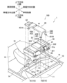
- FIG. 1 is an exploded perspective view showing a protective structure for a vehicle service plug according to an embodiment.
- FIG. 2 is a perspective view showing a protective structure for a vehicle service plug according to an embodiment.
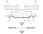
- FIG. 3 is an explanatory diagram schematically showing a cross section taken along line AA in FIG. 2.
- FIG. 3 is a perspective view showing the inside of the vehicle compartment.
- FIG. 2 is an explanatory diagram of the battery pack in an attached state, viewed from the rear and right side in the vehicle width direction. It is a top view which shows a protection member. It is a side view which shows a protection member. It is a back view which shows a protection member. It is a back view which shows the modification of a protection member.
- vehicle longitudinal direction, vehicle width direction (horizontal direction), and vertical direction will be expressed based on a vehicle to which the vehicle body structure according to the embodiment is applied.
- FIG. 1 is an exploded perspective view showing a protective structure for a vehicle service plug according to an embodiment
- FIG. 2 is a perspective view showing a protective structure for a vehicle service plug according to an embodiment
- FIG. 2 is an explanatory diagram schematically showing a cross section along line AA of No. 2.
- FIG. 4 is a perspective view showing the inside of the vehicle compartment.
- the vehicle service plug protection structure 100 according to the embodiment is applied to a vehicle 1 such as a plug-in hybrid vehicle (PHEV), a hybrid vehicle (HEV), or an electric vehicle (BEV) capable of external charging or external power supply.
- PHEV plug-in hybrid vehicle
- HEV hybrid vehicle
- BEV electric vehicle
- the vehicle 1 includes a frame member 10 as a vehicle body structure, a floor panel 11, a dash panel 12, a pair of front seats 20, a battery pack 30, and a protection member 40.
- a portion of the frame member 10, the battery pack 30, and the protection member 40 constitute a service plug protection structure 100 according to the embodiment. Note that in FIG. 1, the illustration of the pair of front seats 20 is omitted, and in FIG. 2, the illustration of the front seat 20 provided on the left side in the vehicle width direction is omitted.
- the floor panel 11 extends in the vehicle longitudinal direction and the vehicle width direction, and forms the bottom of the vehicle interior.
- the dash panel 12 is a member that partitions an engine compartment (not shown) of the vehicle 1 and a vehicle interior, and is connected to the front end of the floor panel 11 and extends while curving upward toward the front.
- the skeleton member 10 includes a pair of side members 13, a pair of side sills 14, a pair of cross members 15, and a backbone 16.
- Each frame member 10 is formed of a steel plate.
- the pair of side members 13 are provided as a pair on the left and right with an interval between them in the vehicle width direction.
- Each side member 13 is connected to the lower surface of the floor panel 11 and the dash panel 12, and extends along the vehicle longitudinal direction.
- the pair of side sills 14 are connected to each end of the floor panel 11 in the vehicle width direction, and extend along the vehicle longitudinal direction.
- the pair of cross members 15 includes a first cross member 151 and a second cross member 152 provided on the rear side of the first cross member 151.
- the first cross member 151 and the second cross member 152 are provided at intervals from each other in the longitudinal direction of the vehicle, extend along the vehicle width direction, and are bridged between the pair of side sills 14 and attached to the floor panel 11. It is connected.
- the first cross member 151 and the second cross member 152 are provided at positions sandwiching a battery pack 30, which will be described later, in the vehicle longitudinal direction.
- the first cross member 151 is formed with a support portion 151a that protrudes upward and supports a pair of front leg portions 43A (see FIGS. 6 and 7) of the protection member 40, which will be described later.
- the backbone 16 extends in the longitudinal direction of the vehicle in a tunnel shape while protruding upward from the floor panel 11 at the center in the vehicle width direction, and is connected to the floor panel 11 and the dash panel 12. Further, in this embodiment, the backbone 16 extends to the first cross member 151 and is connected to the first cross member 151.
- the floor panel 11 includes a housing section 121 for housing the battery pack 30, as shown in FIGS. 1 and 3. is provided.
- the housing portion 121 is a portion of the floor panel 11 that is depressed downward between the first cross member 151 and the second cross member 152 and between the pair of side members 13 .
- the accommodating portion 121 may have a shape that corresponds to the bottom shape of the battery pack 30, and in this embodiment, it is formed into a trapezoidal shape. Note that a heat shielding sheet may be provided between the battery pack 30 and the housing section 121.
- each front seat 20 is fastened to a first cross member 151 and a second cross member 152 via a plurality of legs 21.
- a center console 25 is provided in the space between the pair of front seats 20, as shown in FIG.
- the center console 25 is provided with, for example, a cup holder 251, a shift knob attachment portion 252 (not shown), an armrest 253 for a passenger seated on the front seat 20, and an interior space covered by an exterior cover 254. Note that in FIG. 3, the center console 25 is not shown.
- the battery pack 30 includes a battery module (not shown) having a plurality of battery cells, such as a lithium ion battery, and various devices (not shown) such as a DC-DC converter, and a tray 31 and a cover 32. It is housed and configured.
- the tray 31 is a casing with an open top.
- a plurality of fixing parts 321 for fixing the battery pack 30 to the frame member 10 are provided on the outer periphery of the tray 31 . Note that some of the plurality of fixing parts 321 may be fixed to a pedestal welded to the skeleton member 10.
- the cover 32 is a casing with an open bottom, and is housed inside the tray 31 while blocking the top opening of the tray 31 .
- the battery pack 30 is housed inside a housing portion 121 in which a portion of the tray 31 is formed in the floor panel 11.
- Two mounting brackets 322 are fixed to the battery pack 30, and each mounting bracket 322 is provided with a plurality of fixing parts 321 for fixing the battery pack 30.
- two mounting brackets 322 are fastened to the first cross member 151 and the second cross member 152 at the plurality of fixing parts 321, as illustrated by the dashed line in FIG. That is, the battery pack 30 is suspended above the housing section 121 by the first cross member 151 and the second cross member 152 via the two mounting brackets 322 .
- the battery pack 30 In the fixed state as described above, the battery pack 30 is located below the pair of front seats 20 as shown in FIG. Located in Therefore, the battery pack 30 is arranged between the pair of front seats 20 and the floor panel 11.
- FIG. 5 is an explanatory diagram of the battery pack 30 in an attached state, viewed from the rear side and the right side in the vehicle width direction.
- a service plug 36 is provided on the rear surface 30a of the battery pack 30.
- the service plug 36 is a maintenance/inspection switch for cutting off the power supply circuit at an intermediate point of the battery pack 30 when performing maintenance/inspection of each device to which power is supplied from the battery pack 30 or the battery pack 30 itself.
- the service plug 36 is provided above the boundary surface between the tray 31 and the cover 32, that is, the upper end 31a of the tray 31, in the center of the battery pack 30 in the vehicle width direction. As a result, the service plug 36 is located between the pair of front seats 20 and above the floor 3 of the vehicle interior.
- the service plug 36 is covered by a service lid 37 (cover member).
- a lid support portion 35 (see FIG. 5) is formed on the rear surface 30a of the battery pack 30, and the service lid 37 is supported by the lid support portion 35, and the service lid 37 is attached to a restraining member attached to a protection member 40, which will be described later. 38 prevents it from moving. Note that if the restraining member 38 is removed from the protection member 40, the service lid 37 can be manually attached or detached through the rear opening 40a of the protection member 40. Thereby, when it is necessary to operate the service plug 36 during maintenance and inspection, the service plug 36 can be easily accessed.
- the protection member 40 is provided between the pair of front seats 20 and covers a portion of the battery pack 30 from above. Further, an exterior cover 254 of the center console 25 is attached around the protection member 40. That is, the protection member 40 is interposed between the battery pack 30 and the center console 25, and serves as an attachment part for the center console 25 while protecting the upper part of the battery pack 30. That is, in this embodiment, the protection member 40 is a console bracket that supports the center console 25. Note that a cooling fan (not shown) for supplying cooling air to the battery pack 30 is arranged between the protection member 40 and the center console 25.
- the protection member 40 will be explained with reference to FIGS. 2 and 6 to 8.
- 6 is a top view showing the protection member 40
- FIG. 7 is a side view showing the protection member 40
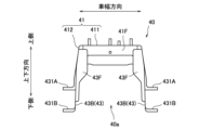
- FIG. 8 is a rear view showing the protection member 40.
- the protection member 40 is formed of a steel plate. Note that the protection member 40 may be any kind of metal member as long as sufficient rigidity and strength can be ensured.
- the protection member 40 has a top plate part 41, a backbone connection part 42, and a plurality of legs 43, as shown in FIGS. 6 to 8.
- the top plate part 41 is a part that covers the upper part of the battery pack 30, and is formed longer than the battery pack 30 in the vehicle front-rear direction. Further, the top plate portion 41 is formed to be wider in the vehicle width direction than the service lid 37 that covers the service plug 36 of the battery pack 30.
- the top plate part 41 includes a base plate part 411 that extends in the vehicle longitudinal direction, and side plate parts 412 that extend downward along both ends of the base plate part 411 in the vehicle width direction.
- a backbone connecting portion 42 for connecting the battery pack 30 to the backbone 16 is attached to the front end 41 a of the top plate portion 41 .
- the rear end 41b of the top plate part 41 is provided with a top plate side flange part 41F that projects downward, as shown in FIG.
- a restraining member 38 for fixing the service lid 37 is detachably attached to the top plate side flange portion 41F with bolts and nuts.
- the top plate portion 41 is formed with an opening 413 for supplying cooling air from a cooling fan (not shown) to the battery pack 30 side.
- the backbone connecting part 42 is fastened to the tip of the top plate part 41, for example.
- the backbone connecting portion 42 may be joined to the top plate portion 41 by welding.
- the backbone connecting part 42 includes a base plate part 421 that extends in the longitudinal direction of the vehicle, and side plate parts 422 that extend downward along both ends of the base plate part 421 in the vehicle width direction.
- the substrate portion 421 is formed wider than the backbone 16 in the vehicle width direction.
- the base plate portion 421 extends downward from the top plate portion 41 side toward the front side, and has a distal end portion extending in the horizontal direction. Thereby, the difference in position between the top plate part 41 and the backbone 16 in the vertical direction is adjusted by the backbone connecting part 42.
- a contact portion 423 extends from the side plate portion 422 of the backbone connecting portion 42 and comes into contact with the side plate portion 412 of the top plate portion 41 and a front leg portion 43A to be described later.
- the plurality of legs 43 includes a pair of front legs 43A and a pair of rear legs 43B.
- the pair of front leg portions 43A are provided one at each end of the front end 41a of the top plate portion 41 in the vehicle width direction.
- Each front leg portion 43A extends downward from the side plate portion 412 of the top plate portion 41.
- each front leg portion 43A extends downward continuously from the side plate portion 412.
- a front fixing portion 431A is formed that extends horizontally outward in the vehicle width direction when viewed from the center line A1 of the protection member 40 (see FIG. 6).
- each front leg portion 43A is formed in a tapered shape so as to extend rearward in the longitudinal direction of the vehicle as it goes from the lower end toward the top plate portion 41 side.
- the pair of rear leg portions 43B are provided one at each end in the vehicle width direction at the rear end 41b of the top plate portion 41.
- Each rear leg portion 43B extends downward from the side plate portion 412 of the top plate portion 41, similarly to each front leg portion 43A.
- each rear leg portion 43B extends downward continuously from the side plate portion 412. Therefore, when viewed from the rear side in the longitudinal direction of the vehicle, the protection member 40 has a gate-like shape formed by the top plate portion 41 and the pair of rear leg portions 43B, as shown in FIG. In other words, the protection member 40 has a rear opening 40a surrounded by the top plate portion 41 and the pair of rear leg portions 43B at the rear end portion.
- a rear fixing portion 431B (fixing portion) is formed at the lower end of each rear leg portion 43B and extends horizontally outward in the vehicle width direction when viewed from the center line A1. Further, as shown in FIG. 7, each rear leg portion 43B is formed in a tapered shape so as to extend forward in the longitudinal direction of the vehicle as it goes from the lower end toward the top plate portion 41 side.
- each rear leg portion 43B is formed with a leg side flange portion 43F that projects inward in the vehicle width direction.
- Each leg side flange portion 43F extends to a position where it overlaps with the top plate side flange portion 41F of the top plate portion 41 when viewed from the longitudinal direction of the vehicle, and is connected to the top plate side flange portion 41F.
- Each leg side flange portion 43F and top plate side flange portion 41F may be connected by welding, or may be connected by fastening using bolts and nuts.
- each leg side flange portion 43F extends in a tapered shape such that the length in the vehicle width direction becomes shorter as it goes downward from the center portion in the vertical direction, and furthermore, in a straight line from the tapered portion to the lower end. Extends to. In this way, the weight of the protection member 40 can be reduced by shortening the length in the vehicle width direction from the center portion in the vertical direction to the lower end of each leg side flange portion 43F.
- the protection member 40 configured as described above is arranged to cover the battery pack 30 from above. Note that, as described above, a space is provided between the upper surface of the battery pack 30 and the protection member 40 in which a cooling fan (not shown) is disposed. Then, as illustrated by the dashed line in FIG. 1, the backbone connecting portion 42 is fixed to the upper surface of the backbone 16 by fastening while covering the backbone 16 from above. Further, the front fixing portion 431A of each front leg portion 43A is supported by the support portion 151a of the first cross member 151, and is fixed to the support portion 151a by fastening. Further, the rear fixing portion 431B of each rear leg portion 43B is supported on the upper surface of the second cross member 152 and fixed to the upper surface by fastening.
- the protection member 40 which is a metal member, functions as one of the vehicle body structures extending in the longitudinal direction of the vehicle so as to connect the backbone 16 and the cross member 15. That is, for example, when a frontal collision occurs in the vehicle 1, a load is transmitted from the backbone 16 to each cross member 15 via the protection member 40.
- the floor panel 11 is provided with the accommodating part 121 for accommodating the battery pack 30, and the backbone 16 is configured to extend only to the front side of the accommodating part 121 in the longitudinal direction of the vehicle. 40 can serve as a load transmission path.
- the battery pack 30 is housed in the housing section 121 between the first cross member 151 and the second cross member 152. Therefore, the pair of front legs 43A of the protection member 40 are located on the front side of the battery pack 30 in the longitudinal direction of the vehicle, and the pair of rear legs 43B are located on the rear side of the rear surface 30a of the battery pack 30.
- the service plug 36 of the battery pack 30 is surrounded by the top plate part 41 of the protection member 40 and the pair of rear leg parts 43B from above and both sides in the vehicle width direction.
- the service plug 36 is exposed through the rear opening 40a of the gate-shaped protection member 40 so as to face the rear seat (not shown). However, the service plug 36 is located on the front side of the protection member 40 in the longitudinal direction of the vehicle.
- the service plug 36 is surrounded and protected by the protection member 40 which is made of metal and functions as one of the frame members 10.
- the service plug 36 is covered by the service lid 37 as described above, and the restraining member 38 is attached to the protective member 40.
- the service plug 36 is covered from the rear side in the longitudinal direction of the vehicle by the rear cover 254a of the center console 25.
- the vehicle service plug protection structure 100 includes the floor panel 11 forming the bottom of the vehicle interior, the frame member 10 as a vehicle body structure provided on the floor panel 11, and the vehicle service plug protection structure 100 according to the embodiment.
- a battery pack 30 for driving the vehicle 1 is placed between a pair of front seats 20 and a floor panel 11 that are spaced apart from each other in the width direction, and a battery pack 30 is placed between the pair of front seats 20.
- a service plug 36 for maintenance and inspection is provided on the rear surface 30a of the battery pack 30.
- the protection member 40 is a metal member and is attached to the frame member 10.
- the service plug 36 is connected and arranged so as to surround the service plug 36 from above and from both sides in the vehicle width direction.
- the service plug 36 is provided on the rear surface 30a of the battery pack 30, and the protection member 40 surrounds the service plug 36 from the upper side and both sides in the vehicle width direction. can be easily accessed. Further, even if a side collision occurs in the vehicle 1, deformation of the peripheral portion of the service plug 36 can be suppressed by the metal protection member 40, which is connected to the frame member 10 and functions as one of the vehicle body structures. can. Therefore, according to the service plug protection structure 100 according to the embodiment, the service plug 36 for maintenance and inspection included in the drive battery pack 30 can be easily accessed and protected in the event of a vehicle collision.
- the protective member 40 extends downward from a top plate portion 41 that covers the battery pack 30 from above between the pair of front seats 20 and both ends in the vehicle width direction at the rear end 41b of the top plate portion 41, and extends downward from both ends in the vehicle width direction. It has a pair of rear leg parts 43B connected to the member 10, and the pair of rear leg parts 43B has a leg side flange part 43F that extends inward in the vehicle width direction and is connected to the top plate part 41.
- the top plate portion 41 of the protection member 40 and the leg side flange portions 43F formed on the pair of rear leg portions 43B are connected, so that the rigidity around the pair of rear leg portions 43B in the vehicle width direction is reduced. can be increased. As a result, when a side collision occurs in the vehicle 1, deformation of the peripheral portion of the service plug 36 can be better suppressed.
- the battery pack 30 includes a service lid 37 that covers the service plug 36, and the top plate portion 41 has a top plate side flange portion 41F that protrudes downward from the rear end 41b and to which a restraining member 38 for suppressing the service lid 37 is attached.
- the leg side flange portion 43F is connected to the top plate side flange portion 41F.
- the pair of rear leg portions 43B includes a rear fixing portion 431B (fixing portion) that extends outward in the vehicle width direction from the lower end and is connected to the frame member 10.
- pair of rear leg portions 43B are formed in a tapered shape so as to extend toward the front in the longitudinal direction of the vehicle from the lower end toward the top plate portion 41.
- the pair of rear leg portions 43B are formed to expand in the longitudinal direction of the vehicle, so that when a frontal collision occurs in the vehicle 1, deformation of the pair of rear leg portions 43B can be suppressed. .
- deformation and change in posture of the battery pack 30 covered by the protection member 40 can be suppressed, and accessibility of the service plug 36 after a vehicle collision can be ensured.
- the frame member 10 is located in front of the battery pack 30 in the vehicle longitudinal direction, and has a backbone 16 that extends in the vehicle width direction central part of the floor panel 11 in a tunnel shape in the vehicle longitudinal direction, and a backbone 16 that sandwiches the battery pack 30 in the vehicle longitudinal direction.
- the protection member 40 includes a pair of cross members 15 (a first cross member 151 and a second cross member 152) extending in the vehicle width direction, and is connected to the backbone 16 and the pair of cross members 15.
- the protection member 40 functions as one of the vehicle body structures that connects the backbone 16 and the pair of cross members 15. Thereby, the protection member 40 can appropriately protect the service plug 36 in the event of a vehicle collision.
- the battery pack 30 is housed in a housing section 121 that is formed by recessing the floor panel 11 downward between the pair of cross members 15 and between the pair of side members 13.
- the service plug 36 is provided above the interface between the tray 31 and the cover 32 of the battery pack 30, that is, the upper end 31a of the tray 31.
- the protective member 40 covers the upper part of the service plug 36, even if an occupant spills a drink or the like around the center console 25 and the liquid enters the center console 25, the protective member prevents the liquid from splashing onto the service plug 36. 40 can be suppressed.
- the service plug 36 is arranged on the rear surface 30a of the battery pack 30, and in normal times when the service plug 36 does not need to be operated, the rear cover 254a of the center console 25 covers the area around the service plug 36 (the service lid 37 and the restraining member 38). is covered.
- the area around the service plug 36 can be hidden without using a dedicated cover member, that is, by using the conventional rear cover 254a of the center console 25. It can improve the appearance of the room.
- the service plug 36 is located on the front side of the rear end of the protection member 40 in the longitudinal direction of the vehicle. With this configuration, it is possible to prevent the feet of an occupant seated in a rear seat (not shown) from colliding with the service plug 36.
- the protection member 40 may be connected to a frame member 10 other than the backbone 16 and the cross member 15 as long as it is configured to function as one of the vehicle body structures. Further, the protection member 40 does not need to function as a console bracket that supports the center console 25.
- leg side flange portions 43F formed on the pair of rear leg portions 43B are not limited to the top plate side flange portions 41F, and may be connected to any position on the top plate portion 41. Further, the leg side flange portion 43F may be omitted from the protection member 40. Further, the top plate side flange portion 41F may be omitted from the protection member 40 if the service lid 37 can be made immovable without using the restraining member 38.
- the pair of rear leg parts 43B do not need to have the rear fixing part 431B extending outward in the vehicle width direction, as long as they can be connected to either of the frame members 10. Further, the pair of rear legs 43B may extend linearly from the lower end to the top plate 41.
- FIG. 9 is a rear view showing a modification of the protection member 40.
- the protection member 40 may include a connecting portion 44 that connects the lower ends of the pair of rear leg portions 43B.
- the connecting portion 44 can further increase the rigidity around the pair of rear leg portions 43B in the vehicle width direction. As a result, when a side collision occurs in the vehicle, deformation of the peripheral portion of the service plug 36 can be better suppressed.
Landscapes
- Engineering & Computer Science (AREA)
- Transportation (AREA)
- Mechanical Engineering (AREA)
- Chemical & Material Sciences (AREA)
- Combustion & Propulsion (AREA)
- Life Sciences & Earth Sciences (AREA)
- Sustainable Development (AREA)
- Sustainable Energy (AREA)
- Power Engineering (AREA)
- Body Structure For Vehicles (AREA)
- Arrangement Or Mounting Of Propulsion Units For Vehicles (AREA)
- Electric Propulsion And Braking For Vehicles (AREA)
Priority Applications (2)
| Application Number | Priority Date | Filing Date | Title |
|---|---|---|---|
| PCT/JP2022/013839 WO2023181235A1 (ja) | 2022-03-24 | 2022-03-24 | 車両のサービスプラグ保護構造 |
| JP2022554648A JP7239907B1 (ja) | 2022-03-24 | 2022-03-24 | 車両のサービスプラグ保護構造 |
Applications Claiming Priority (1)
| Application Number | Priority Date | Filing Date | Title |
|---|---|---|---|
| PCT/JP2022/013839 WO2023181235A1 (ja) | 2022-03-24 | 2022-03-24 | 車両のサービスプラグ保護構造 |
Publications (1)
| Publication Number | Publication Date |
|---|---|
| WO2023181235A1 true WO2023181235A1 (ja) | 2023-09-28 |
Family
ID=85569511
Family Applications (1)
| Application Number | Title | Priority Date | Filing Date |
|---|---|---|---|
| PCT/JP2022/013839 Ceased WO2023181235A1 (ja) | 2022-03-24 | 2022-03-24 | 車両のサービスプラグ保護構造 |
Country Status (2)
| Country | Link |
|---|---|
| JP (1) | JP7239907B1 (https=) |
| WO (1) | WO2023181235A1 (https=) |
Families Citing this family (2)
| Publication number | Priority date | Publication date | Assignee | Title |
|---|---|---|---|---|
| JP7720345B2 (ja) * | 2023-03-31 | 2025-08-07 | ダイハツ工業株式会社 | 電動車 |
| WO2025220167A1 (ja) * | 2024-04-17 | 2025-10-23 | 日産自動車株式会社 | 車両下部構造 |
Citations (5)
| Publication number | Priority date | Publication date | Assignee | Title |
|---|---|---|---|---|
| JP2013023163A (ja) * | 2011-07-25 | 2013-02-04 | Toyota Motor Corp | バッテリ搭載車両の構造 |
| JP2014226972A (ja) * | 2013-05-20 | 2014-12-08 | 三菱自動車工業株式会社 | 自動車の車体構造 |
| JP2016084025A (ja) * | 2014-10-27 | 2016-05-19 | 本田技研工業株式会社 | 車両 |
| JP2019001190A (ja) * | 2017-06-12 | 2019-01-10 | 日産自動車株式会社 | 車両の電源装置の保護構造 |
| JP2020185904A (ja) * | 2019-05-15 | 2020-11-19 | マツダ株式会社 | 電動車両の下部車体構造 |
-
2022
- 2022-03-24 JP JP2022554648A patent/JP7239907B1/ja active Active
- 2022-03-24 WO PCT/JP2022/013839 patent/WO2023181235A1/ja not_active Ceased
Patent Citations (5)
| Publication number | Priority date | Publication date | Assignee | Title |
|---|---|---|---|---|
| JP2013023163A (ja) * | 2011-07-25 | 2013-02-04 | Toyota Motor Corp | バッテリ搭載車両の構造 |
| JP2014226972A (ja) * | 2013-05-20 | 2014-12-08 | 三菱自動車工業株式会社 | 自動車の車体構造 |
| JP2016084025A (ja) * | 2014-10-27 | 2016-05-19 | 本田技研工業株式会社 | 車両 |
| JP2019001190A (ja) * | 2017-06-12 | 2019-01-10 | 日産自動車株式会社 | 車両の電源装置の保護構造 |
| JP2020185904A (ja) * | 2019-05-15 | 2020-11-19 | マツダ株式会社 | 電動車両の下部車体構造 |
Also Published As
| Publication number | Publication date |
|---|---|
| JP7239907B1 (ja) | 2023-03-15 |
| JPWO2023181235A1 (https=) | 2023-09-28 |
Similar Documents
| Publication | Publication Date | Title |
|---|---|---|
| JP7275836B2 (ja) | 電動車両の下部車体構造 | |
| JP4121898B2 (ja) | 高圧電装部品の車載構造 | |
| CN114537117B (zh) | 电池组搭载车辆 | |
| US20200070671A1 (en) | Battery case fixing structure | |
| US8739911B2 (en) | Structure for mounting power supply device in vehicle | |
| US7503585B2 (en) | Rear vehicle structure | |
| JP4259694B2 (ja) | 車両用バッテリの搭載構造 | |
| US9186957B2 (en) | Electric component arrangement structure of vehicle | |
| JP5729207B2 (ja) | 車両の電源装置支持構造 | |
| JP7326376B2 (ja) | 車体構造 | |
| JP4592366B2 (ja) | 車両後部構造 | |
| JP6944972B2 (ja) | 車両用バッテリユニット | |
| JP2013103586A (ja) | 電気自動車の電力制御ユニット支持構造 | |
| WO2023181235A1 (ja) | 車両のサービスプラグ保護構造 | |
| JP5987480B2 (ja) | サービスディスコネクタの保護構造 | |
| JP2019059478A (ja) | 車両用バッテリパックの取付け構造 | |
| JP2014133464A (ja) | 車両用バッテリパック支持構造 | |
| US20220402404A1 (en) | Vehicle seat support structure | |
| JP2017218036A (ja) | 電池パックの保護構造 | |
| JP2016084023A (ja) | 車両 | |
| JP7276638B1 (ja) | 電動車両の車体構造 | |
| EP4124515B1 (en) | Battery unit arrangement structure for vehicle and vehicle | |
| JP7720345B2 (ja) | 電動車 | |
| US20250167693A1 (en) | Inverter mounting structure | |
| JP2026054783A (ja) | 車両骨格構造 |
Legal Events
| Date | Code | Title | Description |
|---|---|---|---|
| WWE | Wipo information: entry into national phase |
Ref document number: 2022554648 Country of ref document: JP |
|
| 121 | Ep: the epo has been informed by wipo that ep was designated in this application |
Ref document number: 22933376 Country of ref document: EP Kind code of ref document: A1 |
|
| NENP | Non-entry into the national phase |
Ref country code: DE |
|
| 122 | Ep: pct application non-entry in european phase |
Ref document number: 22933376 Country of ref document: EP Kind code of ref document: A1 |