WO2023181156A1 - 工作機械 - Google Patents
工作機械 Download PDFInfo
- Publication number
- WO2023181156A1 WO2023181156A1 PCT/JP2022/013438 JP2022013438W WO2023181156A1 WO 2023181156 A1 WO2023181156 A1 WO 2023181156A1 JP 2022013438 W JP2022013438 W JP 2022013438W WO 2023181156 A1 WO2023181156 A1 WO 2023181156A1
- Authority
- WO
- WIPO (PCT)
- Prior art keywords
- workpiece
- contact detection
- robot
- control device
- input value
- Prior art date
- Legal status (The legal status is an assumption and is not a legal conclusion. Google has not performed a legal analysis and makes no representation as to the accuracy of the status listed.)
- Ceased
Links
Images




Classifications
-
- B—PERFORMING OPERATIONS; TRANSPORTING
- B23—MACHINE TOOLS; METAL-WORKING NOT OTHERWISE PROVIDED FOR
- B23Q—DETAILS, COMPONENTS, OR ACCESSORIES FOR MACHINE TOOLS, e.g. ARRANGEMENTS FOR COPYING OR CONTROLLING; MACHINE TOOLS IN GENERAL CHARACTERISED BY THE CONSTRUCTION OF PARTICULAR DETAILS OR COMPONENTS; COMBINATIONS OR ASSOCIATIONS OF METAL-WORKING MACHINES, NOT DIRECTED TO A PARTICULAR RESULT
- B23Q7/00—Arrangements for handling work specially combined with or arranged in, or specially adapted for use in connection with, machine tools, e.g. for conveying, loading, positioning, discharging, sorting
-
- B—PERFORMING OPERATIONS; TRANSPORTING
- B23—MACHINE TOOLS; METAL-WORKING NOT OTHERWISE PROVIDED FOR
- B23Q—DETAILS, COMPONENTS, OR ACCESSORIES FOR MACHINE TOOLS, e.g. ARRANGEMENTS FOR COPYING OR CONTROLLING; MACHINE TOOLS IN GENERAL CHARACTERISED BY THE CONSTRUCTION OF PARTICULAR DETAILS OR COMPONENTS; COMBINATIONS OR ASSOCIATIONS OF METAL-WORKING MACHINES, NOT DIRECTED TO A PARTICULAR RESULT
- B23Q7/00—Arrangements for handling work specially combined with or arranged in, or specially adapted for use in connection with, machine tools, e.g. for conveying, loading, positioning, discharging, sorting
- B23Q7/04—Arrangements for handling work specially combined with or arranged in, or specially adapted for use in connection with, machine tools, e.g. for conveying, loading, positioning, discharging, sorting by means of grippers
Definitions
- the present disclosure relates to a technology for setting a transfer position for transferring a workpiece between a robot and a partner device.
- Patent Document 1 listed below describes an industrial robot that transfers a workpiece to and from a table.
- the industrial robot is an articulated robot that uses its hand to grasp and transport a workpiece placed on a stand.
- a workpiece measurement sensor that measures the length of the workpiece is provided on the table.
- the industrial robot inputs the measurement signal of the workpiece measurement sensor, calculates the longitudinal center position of the workpiece, and sets the grasping position of the hand based on the calculated value.
- the position of the robot needs to be adjusted not only when the above-mentioned workpiece is received by the robot, but also when the workpiece is transferred from the robot to a partner device such as a placing table. Furthermore, due to errors in the accuracy of assembling parts of the robot or the partner device, there is a risk that the workpiece transfer control may not be able to accurately execute the transfer. In the above-mentioned industrial robot technology, it is necessary to provide a workpiece measurement sensor in each partner device that receives a workpiece, which may complicate the entire device.
- the present disclosure has been made in view of the above-mentioned problems, and aims to provide a machine tool that can set the delivery position for delivering a workpiece to a partner device based on measurement results while simplifying the structure of the device. purpose.
- the present specification provides a contact detection device, a robot that has a holding member and that holds a workpiece with the holding member and transports the workpiece, and a partner device that receives the workpiece from the robot. , a control device, the contact detection device outputs a contact detection signal according to the contact to the control device, and the control device controls the robot to cause the contact detection device to contact the partner device.
- a reference position setting for acquiring the contact detection signal from the contact detection device when contact with the partner device is detected, and setting the position of the robot at the time of contact as a reference position based on the acquisition of the contact detection signal; processing, obtaining the length of the workpiece as an input value, and transferring the workpiece having the length of the input value from the robot to the partner device based on the obtained input value and the reference position;
- a machine tool is disclosed that executes a position setting process for setting a delivery position that is the position of the robot.
- the present specification includes a robot having a holding member, holding a workpiece by the holding member and transporting the workpiece, a partner device receiving the workpiece from the robot, and a control device, the robot , the contact detection device can be held by the holding member, the contact detection device outputs a contact detection signal according to the contact to the control device, and the control device is capable of holding the contact detection device by the holding member of the robot.
- a machine tool executes a position setting process for setting a transfer position that is a position of the robot when the workpiece having the length of the input value is transferred from the robot to the partner device.
- the contact detection device of the robot and the counterpart device are brought into contact, and the reference position of the robot is set based on the contact detection signal at the time of contact.
- the control device sets a transfer position for transferring the workpiece from the robot to the partner device, based on the input value indicating the length of the workpiece and the reference position.
- FIG. 2 is a front view of the machine tool according to the present embodiment.
- Block diagram of machine tool FIG. 2 is a perspective view showing the main body of the machine tool with the device cover removed. The right side view of the machine tool in the state of FIG. 3.
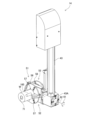
- FIG. 3 is a perspective view of a lifting arm and a head.
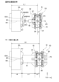
- FIG. 7 is a diagram showing the states of the left spindle device and the head when setting a reference position and transferring a workpiece. The figure which shows the reception screen of a control panel.
- FIG. 7 is a diagram showing the states of the stocker device and the head when setting a reference position and transferring a workpiece.
- FIG. 1 shows a front view of a machine tool 1 of this embodiment.
- FIG. 2 shows a block diagram of the machine tool 1.
- FIG. 3 shows a perspective view of the main body of the machine tool 1 with the device cover 2 (see FIG. 1) removed.
- the Z direction the right direction in the machine width direction and horizontal to the device installation surface
- the Z direction the direction when the machine tool 1 is viewed from the front.
- the front direction parallel to and perpendicular to the Z direction will be referred to as the Y direction
- the Z direction and the upper direction perpendicular to the Y direction will be referred to as the X direction.
- the letter “L” will generally be added to the reference numerals relating to the devices disposed on the left side of the machine tool 1
- the letter “R” will be added to the reference numerals relating to the apparatuses disposed on the right side.
- FIGS. 1 and 2 (Configuration of machine tool 1) As shown in FIGS. 1 and 2, the front surface of the machine tool 1 is covered with a device cover 2, and a movable operation panel 3 is provided on the front surface of the machine.
- the operation panel 3 is movable in the Z direction from the center of the front surface of the device to the right end along a rail 6 provided on the lower right side of the front surface of the device cover 2.
- the device cover 2 is provided with a left front door 5L on the left side of the machine tool 1, and a right front door 5R on the right side.
- the left and right front doors 5L and 5R are, for example, sliding doors, and by opening the doors, it is possible to access the processing space behind the doors.
- the machine tool 1 includes, in addition to the operation panel 3, a left processing device 11L, a right processing device 11R, a stocker device 9, a workpiece transfer device 14, and a control device 15.
- a processing space for a left processing device 11L is provided behind the left front door 5L.
- the left processing device 11L is, for example, a turret-type lathe, and includes a left spindle device 12L and a left turret 13L.
- the left spindle device 12L includes, for example, a plurality of child claws that chuck a workpiece, grips the workpiece with the plurality of child claws, and rotates the workpiece around a main axis parallel to the Z direction.
- the left turret 13L has a tool rest to which a plurality of tools (rotary tools and cutting tools) can be attached, and performs tool indexing.
- the left turret 13L executes machining (cutting, drilling, etc.) on the workpiece gripped by the left spindle device 12L using the indexed tool.
- the user checks the machining state of the workpiece and replaces deteriorated tools through the left front door 5L.
- the right processing device 11R has the same configuration as the left processing device 11L except for the direction of the main axis (device). Therefore, in the description of the right side processing device 11R, description of the same contents as the left side processing device 11L will be omitted.
- a processing space for the right spindle device 12R and the right turret 13R of the right processing device 11R is provided.
- the main axis of the right main spindle device 12R is parallel to the Z direction, and faces (opposes) the main axis of the left main spindle device 12L of the left processing device 11L in the left-right direction. Therefore, the left and right processing devices 11L and 11R are so-called opposed two-axis lathes arranged symmetrically.
- the left and right processing devices 11L and 11R do not have to have a symmetrical configuration. Further, the right processing device 11R may not have the same configuration as the left processing device 11L. For example, at least one of the left processing device 11L and the right processing device 11R may be another type of processing device such as a machining center.
- the machine tool 1 is a multi-tasking machine that has the functions of both an NC lathe and a machining center.
- FIG. 4 is a right side view of the machine tool 1 in the state shown in FIG.
- a tool spindle device 21 is provided approximately at the center of the machine tool 1 in the left-right direction.
- the tool spindle device 21 performs machining that is difficult for the left and right machining devices 11L and 11R, which are lathes.
- the tool spindle device 21 can, for example, perform drilling in addition to lathe processing on the workpieces gripped by the left and right spindle devices 12L and 12R, respectively, and can drill holes at depths that are difficult to perform with the left and right turrets 13L and 13R. This enables workpiece machining at the sheath angle.
- the machine tool 1 includes a multi-tasking machine including left and right processing devices 11L, 11R, and a tool spindle device 21 on one bed 22.
- Each of the left and right spindle devices 12L, 12R rotates the work W (see FIG. 4) based on the drive of spindle motors 14L, 14R provided outside the devices.
- the left and right spindle devices 12L and 12R including the spindle motors 14L and 14R are slidable in a direction parallel to the Z direction along an inclined surface 23 on a bed 22 having a slant bed structure.
- the left and right spindle devices 12L and 12R move in a direction parallel to the Z direction by driving a ball screw mechanism (not shown) by, for example, a Z-axis servo motor 17 (see FIG. 4) provided at the bottom.
- the left and right turrets 13L, 13R and the tool spindle device 21 are both movable in the machine body longitudinal direction and the machine body vertical direction perpendicular to the spindle. For example, while the tool spindle device 21 moves in the horizontal Y direction and the vertical X direction, the left and right turrets 13L and 13R move in the YL direction, which is the Y direction and the It is in the XL direction.
- an automatic tool changer 25 is provided on the front side of the tool spindle device 21.
- the tool spindle device 21 can exchange a tool T (spindle head tool) with an automatic tool changer 25.
- the automatic tool changer 25 is equipped with a tool magazine 25A storing a plurality of tools T at the top of the device, and a tool changer 25B provided at a position facing the tool spindle device 21 exchanges tools T from the tool magazine 25A. , the tool is transported to the tool exchange position of the tool spindle device 21.
- the machine tool 1 can also perform tool exchange in the tool spindle device 21 while machining the workpiece W in each of the left and right machining devices 11L and 11R.
- the machine tool 1 includes, for example, separation shutters (not shown) disposed on both left and right sides of the tool spindle device 21 in the Z direction.
- the machine tool 1 is capable of individually moving two separation shutters in the Y direction by a drive mechanism (not shown).
- FIG. 3 shows a state in which this separation shutter is housed.
- the machine tool 1 separates the machining spaces of the left machining device 11L and the right machining device 11R from the tool exchange space of the tool spindle device 21 by two separation shutters. This makes it possible to prevent each device from being affected by coolant or chips. Further, by closing only one separation shutter, the space including the tool exchange space can be expanded to the machining space for one of the turrets and the tool spindle device 21.
- the work transport device 14 transfers the work W to and from the left and right processing devices 11L, 11R, and each device for carrying in, discharging, inspecting, etc. the work.
- the left and right processing devices 11L, 11R and each device that transfers the workpiece W are examples of counterpart devices of the present disclosure.
- the machine tool 1 includes a stocker device 9 as one of the partner devices. As shown in FIG. 1, the stocker device 9 includes a plurality of pallets 10 on which workpieces W can be stacked, and replaces the pallets 10 at the working position based on the control of the control device 15.
- the workpiece conveyance device 14 receives the workpiece W before processing and delivers the workpiece W after processing to and from the pallet 10 at the working position. Details of the workpiece conveyance device 14 will be described later.
- the operation panel 3 is provided on the front surface of the device cover 2, and includes a touch panel 3A and an operation device 3B.
- the operating device 3B includes, for example, operating switches, push buttons, dials, display lamps, and the like.
- the operation panel 3 receives operation inputs from the user on the touch panel 3A and the operation device 3B, and outputs a signal corresponding to the received operation inputs to the control device 15. Further, the operation panel 3 changes the display content of the touch panel 3A and the lighting state of the display lamp of the operation device 3B based on the control of the control device 15. Furthermore, a pendant 8 for operating the machine tool 1 can be hung below the center of the device cover 2.
- the control device 15 of the machine tool 1 is a processing device mainly composed of a computer, and includes a CPU 15A and a storage device 15B.
- the storage device 15B includes, for example, RAM, ROM, flash memory, and the like.
- the control device 15 is electrically connected to each device (the left processing device 11L, the workpiece transfer device 14, etc.) and can control each device.
- Various control programs 16 are stored in the storage device 15B.
- the control program 16 includes, for example, an NC program that controls the operation of the left and right processing devices 11L and 11R in processing a workpiece, a program that controls the operation of the workpiece conveyance device 14, and a ladder circuit program that processes various signals. It includes programs, etc.
- control program 16 is associated with, for example, the XYZ coordinates of the transfer position where the work transfer device 14 executes the transfer of the workpiece W, the name of the process in which the work is performed at the transfer position, identification information for identifying the process, etc. is memorized.
- the coordinates in each of the XYZ directions will be referred to as the X coordinate, Y coordinate, and Z coordinate. This coordinate system is for convenience of explanation and can be changed as appropriate.
- the setting of each coordinate is not limited to the above-described setting, and for example, the left-right direction (Z direction) may be set as the X coordinate, the front-back direction as the Y coordinate, and the up-down direction (X direction) as the Z coordinate.
- the workpiece conveyance device 14 is, for example, a gantry-type conveyance device, and is capable of moving the gripped workpiece W in three directions, XYZ directions. Note that FIG. 1 illustrates in one figure the state of the workpiece conveyance device 14 that moves to a plurality of positions.
- the machine tool 1 includes a turret-shaped frame structure 31 in which beams are connected to front, rear, left and right columns that are erected to match the width of the bed 22.
- Each device on the bed 22 such as the tool spindle device 21, the automatic tool changer 25, and the workpiece transfer device 14 are covered on the front side by a device cover 2 supported by a frame structure 31.
- the workpiece conveyance device 14 includes a rail stand 32 and a traveling table 33.
- the rail stand 32 is provided on the frame structure 31 and on the front side of the apparatus.
- Two running rails 34 parallel to the Z direction and one running rack 35 are provided on the rail stand 32.
- the traveling table 33 is slidable along the traveling rail 34.
- a traveling motor 37 is fixed to the traveling table 33.
- the traveling table 33 can be moved in the Z direction by a pinion fixed to the rotating shaft of the traveling motor 37 meshing with the traveling rack 35.
- the control device 15 can move the workpiece conveyance device 14 to any position in the Z direction by controlling the travel motor 37.
- a slide table 39 is provided on the top surface of the traveling table 33 so as to be slidable in the Y direction.
- a rack for moving in the Y direction is provided on the side surface of the slide table 39.
- a front and rear motor 41 is fixed to the traveling table 33.
- a pinion fixed to the rotating shaft of the front and rear motor 41 is meshed with a rack of the slide base 39.
- the control device 15 can move the slide base 39 to any position in the Y-axis direction (front-back direction) by controlling the front-back motor 41 .
- the slide table 39 protrudes forward from the frame structure 31, and is provided with an elevating arm 43 that moves up and down at its tip.
- a support column 45 equipped with a lifting rail is fixed to the front end of the slide table 39 in a posture parallel to the X direction.
- a lifting arm 43 is provided in front of the support column 45.
- the lifting arm 43 is movable in the X direction along the lifting rail of the support column 45.
- a lifting motor 47 is provided at the top of the support column 45.
- a pulley is fixed to the rotating shaft of the lifting motor 47.
- a belt is stretched between the pulley of the lifting motor 47 and a pulley pivotally supported at the lower part of the support column 45.
- the lifting arm 43 is connected to the belt, and its position in the X direction is changed according to the driving of the lifting motor 47.
- the control device 15 can change the position of the lifting arm 43 in the X-axis direction (vertical direction) by controlling the lifting motor 47.
- a head 51 for gripping the work W is provided at the lower end 43A of the lifting arm 43. Therefore, the control device 15 can move the head 51 to any position in the XYZ directions by controlling the traveling motor 37, the front-rear motor 41, and the lifting motor 47.
- the head 51 is attached to the rear side surface of the lower end portion 43A, and is arranged at a position on the rear side with respect to the lifting arm 43.
- FIG. 5 shows a perspective view of the lifting arm 43 and head 51.
- the head 51 has two gripping parts, a first gripping part 52 and a second gripping part 53.
- the second grip part 53 has the same configuration as the first grip part 52. Therefore, in the following description, description of the second grip part 53 will be omitted as appropriate.
- the head 51 includes a support member 56, a first claw member 57, and a second claw member 58.
- the support member 56 is attached to the rear of the lower end portion 43A of the lifting arm 43.
- the support member 56 has a substantially rectangular plate shape with a predetermined thickness.
- a first gripping portion 52 and a second gripping portion 53 are provided on each surface of the support member 56 that faces each other in the thickness direction (direction from the left front to the right back in FIG. 5).
- the support member 56 is rotatably attached to the lower end portion 43A.
- the control device 15 rotates the head 51 around a rotation axis 62 (see FIGS.
- the head 51 rotates, for example, in the rotation direction 61 (clockwise or counterclockwise) by 90 degrees in response to the drive of the turning motor.
- the head 51 has a turning position (two turning positions including a 180 degree reversed position) in which each of the first and second gripping parts 52 and 53 is directed to both sides in the Z direction (left and right sides), and a second turning position.
- the first and second gripping parts 52 and 53 are rotated to a total of four rotational positions (two rotational positions including a 180 degree inverted position) in which each of the first and second gripping parts 52 and 53 is directed to both sides in the X direction (both upper and lower sides). do.
- the control device 15 sets the head 51 to the first rotation position RP1.
- the control device 15 controls the first gripping part 52 to face downward.
- the head 51 is rotated to the fourth rotation position RP4.
- the rotation angle and pivot position of the head 51 described above are merely examples.
- the head 51 may be configured to rotate at intervals of an angle larger than 90 degrees (such as 180 degrees), or at intervals of a small angle (such as 45 degrees), or may be configured to rotate at an arbitrary rotation angle.
- three first claw members 57 can be attached to the first grip part 52.
- Each of the three first claw members 57 has, for example, the same shape and is attached at a position shifted by 120 degrees in the circumferential direction.
- the three first claw members 57 are removably attached to the support member 56, and can be replaced with a different type of first claw member 57 depending on the type of work W or the like.
- the three first claw members 57 slide (open and close) in the radial direction in accordance with the drive of a hydraulic cylinder (not shown) provided in the head 51.
- the control device 15 closes the three first claw members 57 to clamp the workpiece W, or opens the three first claw members 57 to release the clamping by driving the hydraulic cylinder.
- the second gripping portion 53 is capable of attaching and detaching, for example, three second claw members 58, and the second claw members 58 can be opened and closed.
- the control device 15 executes processing on the workpiece W based on the control program 16.
- the workpiece W to be processed is transported from the stocker device 9 to the left spindle device 12L and the right spindle device 12L by the workpiece transfer device 14, for example.
- the control device 15 executes predetermined machining using the left and right turrets 13L, 13R and the tool spindle device 21.
- the control device 15 receives the processed workpiece W from the left spindle device 12L or the like to the workpiece transfer device 14, and transfers it to the stocker device 9.
- the XYZ coordinates of the transfer position which is the position of the head 51 that transfers the work W between the work transfer device 14 and each partner device.
- the control device 15 places the head 51 at the delivery position (XYZ coordinates) set in this NC program, turns the head 51 to a predetermined turning position, and transfers the workpiece W between the head 51 and the partner device. do.
- the machine tool 1 of this embodiment is capable of setting a reference position, which is a reference for setting a delivery position, using a contact detection device.
- the control device 15 uses the length of the workpiece W input by the user as an input value, and corrects each delivery position based on a preset reference position and the length of the input value.
- the upper diagram shows the state of the left spindle device 12L and the head 51 when setting the reference position
- the lower diagram shows the state of the left spindle device 12L and the head 51 when the workpiece is transferred.
- a master work 63 is attached to the left spindle device 12L when setting the reference position. This master work 63 is used as a member brought into contact with the contact detection device 65 when setting the reference position P1, and is also used as a member for checking misalignment of the main spindle during centering work of the main spindle.
- the master work 63 includes, for example, a disc-shaped clamped part 63A and a substantially cylindrical convex part 63B protruding from the center of the clamped part 63A. Note that the shape of the master work 63 shown in FIG. 6 is an example.
- the left spindle device 12L is capable of attaching a plurality of (for example, three) child claws 67 that can hold the workpiece W or the master workpiece 63, for example.
- Each of the plurality of child claws 67 has, for example, the same shape, and is attached at a position shifted in the circumferential direction by a predetermined rotation angle (for example, 120 degrees). Further, the plurality of child claws 67 move in the radial direction based on the drive of a drive source (such as a hydraulic cylinder) provided in the left spindle device 12L, and grip the workpiece W and the master workpiece 63.
- a drive source such as a hydraulic cylinder
- the member that holds the workpiece W and the master workpiece 63 is not limited to the claw members such as the child claws 67, but may be other members such as a collet chuck.
- the master work 63 is held between the plurality of child claws 67.
- the user operates the operation panel 3 to open the child claws 67 and seats the master work 63 on the left spindle device 12L.
- the user operates the operation panel 3 to close the sub-claws 67 and causes the sub-claws 67 to clamp the clamped portion 63A of the master work 63.
- the master work 63 is placed in contact with the abutment portion 67A formed on the child pawl 67, and is restricted from moving toward the base end side (left side in FIG. 6) of the left spindle device 12L.
- the centers of the pinched portion 63A and the convex portion 63B are on the main shaft 69. That is, when the master work 63 is placed at the correct position for measurement, movement toward the proximal end is restricted, and the center of rotation is on the main shaft 69.
- the work of placing the master work 63 on the left spindle device 12L may be automatically performed by the head 51 of the work transfer device 14.
- the control device 15 causes the head 51 to grip the master work 63 placed in the stocker device 9, transports the master work 63 to the left spindle device 12L, and transfers the master work 63 from the head 51 to the left spindle device 12L. Masterwork 63 may also be handed over to 12L.
- the user When the user installs the master work 63 on the left spindle device 12L, the user causes the contact detection device 65 to be held by the first gripping portion 52 of the head 51.
- the operation of holding the contact detection device 65 between the heads 51 may be carried out by the user operating the operation panel 3 similarly to the master work 63, or the contact detection device 65 may be placed in the stocker device 9, work station, etc. Alternatively, the head 51 may automatically grab it.
- the first claw member 57 has a different shape when setting the reference position (upper figure) and when transferring the workpiece (lower figure).
- the first claw member 57 is preferably changed to one suitable for holding the contact detection device 65 and the workpiece W, but the same type of first claw member 57 is used when setting the reference position and when transferring the workpiece. It's okay.
- the contact detection device 65 is, for example, a touch probe, and when the tip of the stylus 65A comes into contact with another member, it transmits a contact detection signal indicating the occurrence of contact via wireless communication.
- the control device 15 includes a wireless device 18 that can communicate wirelessly with the contact detection device 65.
- the control device 15 is capable of receiving a contact detection signal SI from the contact detection device 65 held by the first claw member 57 of the head 51 via wireless communication.
- the contact detection method in the contact detection device 65 is not particularly limited, but a movable contact method, a pressure sensor method, an optical sensor method, etc. can be adopted.
- the contact detection device of the present disclosure is not limited to a touch probe, and may use a push button switch having a movable contact or a pressure sensor.
- the method of transmitting the contact detection signal SI to the control device 15 is not limited to wireless communication, but may be a method using infrared rays or electromagnetic induction. Further, the contact detection signal SI may be transmitted by wired communication.
- the control device 15 places the head 51 at a predetermined measurement start position P2 (see FIG. 6).
- This measurement start position P2 is a position where the head 51 is placed when starting measurement of the reference position P1. For example, if the head 51 is placed at the measurement start position P2 in FIG. 6 by performing centering work etc. in advance, the X coordinate in the X direction and the Y coordinate in the Y direction of the head 51 at the measurement start position P2 are This coincides with the XY coordinates of the main axis 69 of 12L.
- the control device 15 brings the stylus 65A of the contact detection device 65 into contact with a plurality of locations on the convex portion 63B of the master work 63 based on the user's operation instruction, detects the center position of the convex portion 63B, The amount of deviation from the main shaft 69 is corrected and centering is performed.
- the control device 15 moves the head 51 in the Z direction and sets the Z coordinate in the Z direction based on the detection by the contact detection device 65.
- the control device 15 can use the XY coordinates of the main axis as the XY coordinates. Therefore, the control device 15 sets the XY coordinates of the main shaft 69 (XY coordinates of the measurement start position P2) determined by performing the centering operation as the XY coordinates of the reference position P1.
- the control device 15 When the head 51 is placed at the measurement start position P2, the control device 15 keeps the XY coordinates constant and moves the head 51 toward the left spindle device 12L along a direction parallel to the Z direction (from the measurement start position P2 in FIG. 6). (see arrow). The control device 15 controls the travel motor 37 to move the head 51 in a direction parallel to the Z direction.
- the contact detection device 65 transmits a contact detection signal SI when the stylus 65A contacts the surface of the convex portion 63B on the head 51 side. Upon acquiring the contact detection signal SI from the contact detection device 65, the control device 15 sets the Z coordinate of the reference position P1.
- the control device 15 corrects the delay time necessary for transmitting the contact detection signal SI from the contact detection device 65 to the control device 15 with respect to the time when the contact detection signal SI is acquired, and Calculate the output time when is output. Then, the control device 15 sets the Z coordinate where the head 51 was placed at the output time as the Z coordinate of the reference position P1.
- the Z coordinate of the head 51 can be detected based on the position information of the traveling motor 37 described above. Note that the control device 15 does not need to perform the above-described transmission time delay correction.
- the control device 15 may set the Z coordinate of the head 51 at the time when the contact detection signal SI is input as the Z coordinate of the reference position P1.
- the control device 15 sets, for example, the distance along the Z direction from the origin position P3 to the reference position P1 shown in FIG. 6 as the reference distance L1.
- This origin position P3 is a reference position (origin) for determining the delivery position.
- the origin position P3 may be set at a position other than the left spindle device 12L (such as a predetermined position on the frame structure 31). That is, the origin position P3 is not limited to the position of the left spindle device 12L, but can be set at any position of the machine tool 1.
- the control device 15 displays on the operation panel 3 that the reference position setting process is completed.
- the user confirms the completion indication, the user removes the contact detection device 65 from the head 51, removes the master work 63 from the left spindle device 12L, and replaces the first claw member 57 with one suitable for the workpiece W to be machined.
- the control device 15 receives the length of the workpiece W to be machined before processing the workpiece W.
- the control device 15 may perform the process of accepting this length as an input value before receiving the processing start instruction.
- the control device 15 displays on the touch panel 3A a reception screen for inputting the length of the workpiece W in response to a predetermined operation input on the touch panel 3A.
- FIG. 7 shows an example of a reception screen 73 for inputting the length of the work W.
- the control device 15 receives information such as the position name, the weight of the workpiece W, the length of the workpiece W, the turning position, and whether or not there is a transfer as input values. Note that the input values shown in FIG. 7 are just an example.
- the control device 15 sets the position names NO1 to NO6 as the names of the delivery positions for these six deliveries, and identifies the delivery positions.
- the head 51 receives the workpiece W from the stocker device 9 to the first gripping section 52 at position number NO1, and transfers the workpiece W from the first gripping section 52 to the left spindle device 12L at position number NO2.
- the head 51 receives the work W after the first machining process from the left spindle device 12L to the first gripping section 52 at NO3, and delivers the work W from the first gripping section 52 to the right spindle device 12R at NO4. Then, the head 51 receives the workpiece W after the second machining process from the right spindle device 12R at NO5, and delivers the workpiece W to the stocker device 9 at NO6.
- input value names 75 for explaining each input value are displayed. Further, below each input value name 75, an input field 76 is provided for inputting each input value for each position name (delivery position).
- the top position name NO1 is a delivery position where the unprocessed workpiece W is delivered from the stocker device 9 to the first gripping section 52. Therefore, the user inputs the weight of the unprocessed work W as the input value weight X1, and inputs the length of the unprocessed work W as the length Y1 in the input field 76. For example, when inputting the weight X2 and length Y2 of No.
- the user inputs the weight X2 that has become lighter and the length Y2 that has become shorter due to the first processing step. Further, the user can input, for example, information on the rotational position of the head 51 for each position name (first to fourth rotational positions RP1 to RP4) and information on whether or not to transfer the workpiece W from the head 51 on the reception screen 73. Enter.
- the control device 15 stores the input value on the reception screen 73 in the storage device 15B, and uses it to correct the delivery position, which will be described later. In this way, the control device 15 receives the length of the workpiece W as an input value for each delivery position.
- the control device 15 discards the information received on the reception screen 73.
- the method for obtaining the weight input value is not limited to the method of inputting it using the operation panel 3 described above, and for example, a setting file in which the input value is written may be read into the control device 15.
- the control device 15 may not accept the length input value on the reception screen 73 in advance, but may accept the length input value after receiving the machining start instruction and before starting the machining.
- the screen configuration of the reception screen 73 in FIG. 7 is an example, and the reception screen 73 does not need to include information such as weight, turning position, and information on whether or not there is a delivery.
- the control device 15 receives the length L2 (see FIG. 6) of the unprocessed workpiece W as the length Y1 of the workpiece W having the position name NO2.
- the user may input, for example, a value on the drawing (design) of the unprocessed workpiece W, or a value obtained by actually measuring the workpiece W before processing.
- the control device 15 uses the received length L2 of the workpiece W to set the delivery position of position name NO2. For example, as shown in the lower diagram of FIG.
- the control device 15 calculates a designed position P5, which is the designed position of the head 51 during delivery, based on the length L2 of the received workpiece W.
- the designed position P5 is, for example, a calculated position taking into consideration the designed length of each member, and does not include an error in the Z direction due to an assembly error of the members.
- the workpiece W transferred from the first gripping part 52 comes into contact with the abutting part 67A of the sub-claws 67 and is seated, and is held between the plural sub-claws 67.
- the XY coordinates of the designed position P5 have been adjusted, for example, by centering work, and therefore are the same coordinates as the reference position P1.
- the distance L4 corresponds to the distance from the origin position P3 to the workpiece W held by the sub-jaw 67 of the left spindle device 12L, and can be set in advance according to the structure of the sub-jaw 67, etc.
- the distance L5 is, for example, the distance from the end of the workpiece W held by the first claw member 57 on the support member 56 side to the center of the head 51, and can be set in advance according to the structure of the head 51 and the like.
- the control device 15 calculates a correction distance L6 that is the difference between the distance L3 and the reference distance L1 calculated at the time of setting the reference position.
- the control device 15 can set the delivery position with the error corrected. Specifically, for example, as shown in FIG. 6, the control device 15 sets a position obtained by adding a correction distance L6 to the reference distance L1 in the Z direction as the Z coordinate of the delivery position P6 of position name No. 2. Correct the Z coordinate with .
- the delivery position P6 is on the right side of the reference position P1, but the positional relationship is changed depending on the length of the contact detection device 65 and the workpiece W.
- the control device 15 sets this transfer position P6 in the NC program, and sets it as the transfer position of position name NO2 for transferring the workpiece W from the first gripping section 52 to the left spindle device 12L. Thereby, it is possible to set the delivery position P6 in which parts assembly errors and the like have been corrected, and the workpiece W can be delivered with high accuracy.
- the control device 15 transfers the workpiece W from the head 51 to the left spindle device 12L using the set transfer position P6. Specifically, when the head 51 holding the work W is placed at the delivery position P6, the control device 15 causes the child claws 67 to grip the work W. After releasing the chuck of the first claw member 57 and retracting the head 51, the control device 15 rotates the left spindle device 12L to start machining.
- the control device 15 of this embodiment sets the reference position P1 using the origin position P3 of the left spindle device 12L as a reference.
- the reference position P1 can be set with high precision by using a predetermined position of the left spindle device 12L, which is the counterpart device, as the origin, and using the measurement result of the contact detection device 65 with the origin as a reference.
- the control device 15 calculates the designed position P5 of the head 51 based on the input length of the workpiece W and the origin position P3 of the left spindle device 12L.
- the control device 15 corrects the delivery position P6 based on the difference (correction distance L6) between the designed position P5 and the reference position P1.
- the corrected distance L6 can be calculated with high accuracy using the reference distance L1, which is an actual measurement value, and the designed distance L3.
- the method for calculating the correction distance L6 is not limited to the method using the origin position P3 described above, but may also be based on the initial position of the workpiece transport device 14, etc., for example.
- the control device 15 uses the contact detection device 65, which is a touch probe, to bring the stylus 65A into contact with the left spindle device 12L (master work 63), and acquires the contact detection signal SI through wireless communication. .
- the control device 15 sets the reference position P1 based on the position of the head 51 at the timing when the contact detection signal SI is output. This eliminates the need for a cable connecting the contact detection device 65 and the control device 15 when the head 51 holds the contact detection device 65 for measurement.
- each machine tool 1 can acquire the contact detection signal SI from the contact detection device 65, and the contact detection device 65 can be reused by the plurality of machine tools 1. can do. It is not necessary to provide the contact detection device 65 in every machine tool 1, and the manufacturing cost of the machine tool 1 can be reduced.
- the control device 15 acquires, as the length L2 of the workpiece W, the length along the spindle 69 of the workpiece W held by the left spindle device 12L as an input value.
- the control device 15 sets a delivery position P6 in the Z direction parallel to the main shaft 69 based on the acquired input value and the reference position P1. Thereby, the error in the delivery position P6 in the direction along the main shaft 69 of the left main shaft device 12L can be corrected using the input value.
- the delivery position with position name No. 2 was explained, but correction can be made in the same way for other delivery positions.
- machining is performed twice, so the length of the workpiece W is the unmachined length Y1, the length after the first machining step Y2, and the second machining step.
- the control device 15 receives the three types of lengths Y1, Y2, and Y3 described above, as shown in the reception screen 73 of FIG.
- the control device 15 sets the reference position P1 and reference distance L1 necessary for other position names No. 1, 3 to 6, as well as the above-mentioned position name No. Execute using Further, as shown in FIG. 7, the control device 15 receives three types of lengths Y1, Y2, and Y3 as input values.
- the control device 15 may accept the length values themselves as input values for the three types of lengths Y1, Y2, and Y3, or may accept the differences in length.
- the control device 15 may receive the unprocessed length Y1 and the length difference that becomes shorter after each processing step.
- the control device 15 uses the unprocessed length Y1 for position names Nos. 1 and 2, uses the length Y2 after the first machining process for position names Nos. 3 and 4, and uses the length Y2 after the first machining process for position names Nos. 5 and 6. Correction is performed using the length Y3 after the second processing step.
- the control device 15 inputs, for example, the length Y1 of the workpiece W before processing as a first input value, and the length Y2 of the workpiece W after processing is completed by the left processing device 11L as a second input value.
- the length Y3 of the workpiece W after the processing is completed by the right processing device 11R is obtained as the third input value.
- the control device 15 sets a transfer position P6 when transferring the workpiece W to the left processing device 11L based on the length Y1. Further, the control device 15 sets the transfer position when transferring the workpiece W to the right processing device 11R based on the length Y2. Further, the control device 15 sets the transfer position when transferring the workpiece W to the stocker device 9 based on the length Y3.
- FIG. 8 shows, as an example, the case where the workpiece W is transferred between the head 51 and the stocker device 9.
- the pallet 10 in FIG. 8 is the pallet 10 placed at the working position of the stocker device 9.
- the pallet 10 of the stocker device 9 is provided with a plurality of positioning pins 10A.
- the work W placed on the upper surface of the pallet 10 is placed with its axial direction aligned with the up-down direction by a plurality of positioning pins 10A.
- the head 51 transfers the workpiece W to and from the pallet 10, for example, at the fourth rotation position RP4 with the first gripping part 52 facing downward.
- the control device 15 corrects the X coordinate in the X direction. As shown in the upper diagram of FIG.
- the control device 15 uses the contact detection device 65 held by the head 51 as a reference in the Set position P1.
- the control device 15 receives, for example, the length of the unprocessed workpiece W (the length Y1 of the position name No. 1 on the reception screen 73) as the length of the workpiece W when the workpiece W is received from the pallet 10 to the head 51. Further, the control device 15 receives the length after the second processing (length Y3 of position name No. 6 on the reception screen 73) as the length to deliver the workpiece W to the pallet 10. Then, the control device 15 calculates the distance L3 in the X direction and the correction distance L6 based on the received lengths Y1 and Y3, and corrects the X coordinate of the delivery position P6 of the position names NO1 and NO6.
- the control device 15 performs various operations such as transferring the unprocessed workpiece W, transferring the processed workpiece W, transferring the workpiece W from the head 51 to the other device, and receiving the workpiece W from the other device to the head 51.
- the delivery position P6 can be set for each case.
- the control device 15 calculates the correction distance L6 and the reference position P1 based on the respective lengths Y1 to Y3, as in the case of FIG. 6 described above. Accordingly, the delivery position P6 can be corrected with high accuracy.
- the user can change the delivery position of each position by changing each length Y1 to Y3.
- the same reference position P1 and reference distance L1 can be used for different types of workpieces W. Even if the types of workpieces W are different, the same reference position P1 can basically be used as long as the distance between the left spindle device 12L and the head 51 varies depending on the length of the workpiece W. For example, the user inputs the length of the workpiece W to be processed next on the reception screen 73 each time a setup change is made to change the workpiece W to be processed.
- the control device 15 sets the transfer position P6 when transferring an arbitrary work W from the head 51 to the partner device, and when setting the transfer position P6 for a work W different in type from the arbitrary work W. , using the same reference position P1.
- the reference position setting process using the contact detection device 65 may be performed every time the setup is changed.
- the stocker device 9 is an example of a counterpart device and a placing stand.
- the left spindle device 12L is an example of a counterpart device, a first spindle device.
- the right spindle device 12R is an example of a counterpart device, a second spindle device.
- the left turret 13L is an example of a first processing device.
- the right turret 13R is an example of a second processing device.
- the work transfer device 14 is an example of a robot.
- the tool spindle device 21 is an example of the first and second processing devices.
- the first claw member 57 and the second claw member 58 are examples of holding members.
- the lengths Y1, Y2, and Y3 are examples of the first input value, the second input value, and the third input value.
- the control device 15 brings the contact detection device 65 held by the head 51 into contact with the left spindle device 12L, and based on the acquisition of the contact detection signal SI of the contact detection device 65, the control device 15 causes the head 51 to A reference position P1 is set. This makes it possible to set the reference position P1 that takes into account errors in assembly accuracy of components such as the head 51. Then, the control device 15 obtains the length L2 of the workpiece W as an input value, and sets a transfer position P6 for transferring the workpiece W from the head 51 to the left spindle device 12L based on the input value and the reference position P1. do. Thereby, there is no need to provide a sensor or the like in the counterpart device, and the delivery position P6 can be set accurately based on the measurement results while simplifying the entire device of the machine tool 1.
- the machine tool 1 may be configured to include (permanently installed) the contact detection device 65.
- the contact detection device 65 may be permanently installed at a stand where the workpiece W is placed or a station where a tool is placed.
- the control device 15 may pick up the contact detection device 65 using the workpiece transport device 14 and perform the measurement when measurement or the like is necessary.
- a contact detection device 165 may be attached to the head 51, as shown by the broken line in FIG.
- the contact detection device 165 may be configured, for example, to be able to extend and retract the stylus 65A, and may be configured to project the stylus 65A further forward than the first claw member 57 during measurement under the control of the control device 15. Further, the contact detection device 165 may have a configuration in which the stylus 65A is housed within the support member 56 when measurement is not performed. In this way, the machine tool 1 may include the contact detection device 165 as a part of the device. Furthermore, the configuration of the head 51 in the above embodiment is merely an example. For example, although the second gripping part 53 has the same structure as the first gripping part 52, it may have a different structure. The number of second claw members 58 may be greater than the number of first claw members 57.
- first and second gripping parts 52 and 53 are provided at positions rotated by 180 degrees, the present invention is not limited thereto.
- the second gripping part 53 may be provided at a position rotated by 90 degrees from the first gripping part 52.
- the head 51 may include only the first gripping portion 52 and may not include the second gripping portion 53.
- the reference position P1 may be set by bringing the contact detection device 65 into contact with the center of the head 51 side surface of the left spindle device 12L (the center surrounded by the plurality of child claws 67, the position on the main spindle 69). . Therefore, in the above embodiment, the master work 63 is used as the member of the partner device with which the contact detection device 65 comes into contact, but the invention is not limited to this. For example, when the left spindle device 12L is provided with a stopper for seating the workpiece W and gripping the workpiece W between it and the child claw 67, the member with which the contact detection device 65 comes into contact may be a stopper.
- the member with which the contact detection device 65 comes into contact may be the main claw.
- the chuck of the left spindle device 12L is a collet chuck
- the member with which the contact detection device 65 comes into contact may be a collet chuck.
- the counterpart devices are not limited to the left and right spindle devices 12L, 12R, and the stocker device 9, but include, for example, a work reversing device that reverses the direction of the work W, and a workpiece W that is placed for the user to check after processing.
- the machine tool 1 may also be a temporary storage stand for discharging workpieces W, or a discharge chute for discharging defective workpieces W.
- the machine tool 1 is equipped with a plurality of partner devices (left and right spindle devices 12L, 12R, stocker device 9) as partner devices of the present disclosure, only one partner device (for example, one main spindle device) is provided. It is also possible to have a configuration with only one).
- the control device 15 may execute the reference position setting process for each type of workpiece W.
- the robot in the present disclosure is not limited to the above-described gantry type loader, but may be an articulated robot.
- the left and right processing devices 11L and 11R are not limited to lathes with two opposing axes, but may be lathes with two parallel axes. Furthermore, various configurations can be adopted as the left and right processing devices 11L and 11R, such as a horizontal lathe, a front lathe, a vertical lathe, a machining center, a milling machine, and a drilling machine.
Landscapes
- Engineering & Computer Science (AREA)
- Mechanical Engineering (AREA)
- Numerical Control (AREA)
- Feeding Of Workpieces (AREA)
Priority Applications (2)
| Application Number | Priority Date | Filing Date | Title |
|---|---|---|---|
| PCT/JP2022/013438 WO2023181156A1 (ja) | 2022-03-23 | 2022-03-23 | 工作機械 |
| JP2024508878A JP7791985B2 (ja) | 2022-03-23 | 2022-03-23 | 工作機械 |
Applications Claiming Priority (1)
| Application Number | Priority Date | Filing Date | Title |
|---|---|---|---|
| PCT/JP2022/013438 WO2023181156A1 (ja) | 2022-03-23 | 2022-03-23 | 工作機械 |
Publications (1)
| Publication Number | Publication Date |
|---|---|
| WO2023181156A1 true WO2023181156A1 (ja) | 2023-09-28 |
Family
ID=88100437
Family Applications (1)
| Application Number | Title | Priority Date | Filing Date |
|---|---|---|---|
| PCT/JP2022/013438 Ceased WO2023181156A1 (ja) | 2022-03-23 | 2022-03-23 | 工作機械 |
Country Status (2)
| Country | Link |
|---|---|
| JP (1) | JP7791985B2 (https=) |
| WO (1) | WO2023181156A1 (https=) |
Citations (4)
| Publication number | Priority date | Publication date | Assignee | Title |
|---|---|---|---|---|
| JPH03213241A (ja) * | 1990-01-17 | 1991-09-18 | Murata Mach Ltd | ワーク搬送方法 |
| JPH11333672A (ja) * | 1998-05-22 | 1999-12-07 | Okuma Corp | ワーク搬送装置 |
| US6257077B1 (en) * | 1998-09-08 | 2001-07-10 | Alan C. Patterson | Remotely powered sensing arrangement for a rotatable device |
| JP2002187041A (ja) * | 2000-12-19 | 2002-07-02 | Murata Mach Ltd | ローダ制御装置 |
Family Cites Families (1)
| Publication number | Priority date | Publication date | Assignee | Title |
|---|---|---|---|---|
| JPH10301609A (ja) * | 1997-04-28 | 1998-11-13 | Denso Corp | ロボットの位置誤差検出方法及びその装置 |
-
2022
- 2022-03-23 WO PCT/JP2022/013438 patent/WO2023181156A1/ja not_active Ceased
- 2022-03-23 JP JP2024508878A patent/JP7791985B2/ja active Active
Patent Citations (4)
| Publication number | Priority date | Publication date | Assignee | Title |
|---|---|---|---|---|
| JPH03213241A (ja) * | 1990-01-17 | 1991-09-18 | Murata Mach Ltd | ワーク搬送方法 |
| JPH11333672A (ja) * | 1998-05-22 | 1999-12-07 | Okuma Corp | ワーク搬送装置 |
| US6257077B1 (en) * | 1998-09-08 | 2001-07-10 | Alan C. Patterson | Remotely powered sensing arrangement for a rotatable device |
| JP2002187041A (ja) * | 2000-12-19 | 2002-07-02 | Murata Mach Ltd | ローダ制御装置 |
Also Published As
| Publication number | Publication date |
|---|---|
| JPWO2023181156A1 (https=) | 2023-09-28 |
| JP7791985B2 (ja) | 2025-12-24 |
Similar Documents
| Publication | Publication Date | Title |
|---|---|---|
| JP5073340B2 (ja) | ワーク加工システム | |
| US11376739B2 (en) | Workpiece transport robot | |
| US20170355052A1 (en) | Handling apparatus for use at a machine tool | |
| JP7545488B2 (ja) | 自動工具交換装置 | |
| CN107405748A (zh) | 机床 | |
| CN113639702A (zh) | 一种加工及平面度检测的自动化系统及方法 | |
| CN112888533B (zh) | 工件自动搬运机 | |
| JP2009533229A (ja) | コンパクトで高精度のコンピュータ制御式多スピンドル工作機械 | |
| US20210379709A1 (en) | Machining center and workpiece processing method | |
| WO2004037485A1 (ja) | 工作機械におけるワーク位相決め方法と、その装置 | |
| JP2003275941A (ja) | Nc工作機械 | |
| WO2026004624A1 (ja) | 表示制御装置 | |
| JP7791985B2 (ja) | 工作機械 | |
| JPS61231406A (ja) | 寸法測定装置 | |
| JP7796206B2 (ja) | 工作機械 | |
| JP4898290B2 (ja) | 測定機能付電動チャックを備えたワーク搬送装置 | |
| JPH11333672A (ja) | ワーク搬送装置 | |
| KR102479602B1 (ko) | 공작기계 및 그 제어방법 | |
| JP7572453B2 (ja) | ワーク自動搬送装置のティーチングシステム | |
| JPH11188513A (ja) | 工作機械のチャックの自動交換方法及び自動チャック交換装置 | |
| JP7675905B6 (ja) | ロボット制御装置およびロボット制御方法 | |
| WO2026004177A1 (ja) | 搬送システムおよびロボット | |
| JP7516718B2 (ja) | 加工システム | |
| JP2783013B2 (ja) | 自動段替え装置 | |
| JP2026006536A (ja) | 加工システム |
Legal Events
| Date | Code | Title | Description |
|---|---|---|---|
| 121 | Ep: the epo has been informed by wipo that ep was designated in this application |
Ref document number: 22933301 Country of ref document: EP Kind code of ref document: A1 |
|
| WWE | Wipo information: entry into national phase |
Ref document number: 2024508878 Country of ref document: JP |
|
| NENP | Non-entry into the national phase |
Ref country code: DE |
|
| 122 | Ep: pct application non-entry in european phase |
Ref document number: 22933301 Country of ref document: EP Kind code of ref document: A1 |