WO2023181156A1 - Machine tool - Google Patents
Machine tool Download PDFInfo
- Publication number
- WO2023181156A1 WO2023181156A1 PCT/JP2022/013438 JP2022013438W WO2023181156A1 WO 2023181156 A1 WO2023181156 A1 WO 2023181156A1 JP 2022013438 W JP2022013438 W JP 2022013438W WO 2023181156 A1 WO2023181156 A1 WO 2023181156A1
- Authority
- WO
- WIPO (PCT)
- Prior art keywords
- workpiece
- contact detection
- robot
- control device
- input value
- Prior art date
Links
- 238000001514 detection method Methods 0.000 claims abstract description 106
- 238000012384 transportation and delivery Methods 0.000 claims abstract description 47
- 238000000034 method Methods 0.000 claims abstract description 41
- 230000008569 process Effects 0.000 claims abstract description 31
- 238000012545 processing Methods 0.000 claims description 70
- 238000012546 transfer Methods 0.000 claims description 49
- 238000004891 communication Methods 0.000 claims description 6
- 239000000523 sample Substances 0.000 claims description 5
- 238000005259 measurement Methods 0.000 abstract description 27
- 210000000078 claw Anatomy 0.000 description 41
- 238000003754 machining Methods 0.000 description 31
- 238000010586 diagram Methods 0.000 description 10
- 238000007514 turning Methods 0.000 description 10
- 238000012937 correction Methods 0.000 description 9
- 241001422033 Thestylus Species 0.000 description 7
- 230000032258 transport Effects 0.000 description 6
- 230000008859 change Effects 0.000 description 5
- 238000000926 separation method Methods 0.000 description 5
- 238000003860 storage Methods 0.000 description 5
- 238000013461 design Methods 0.000 description 4
- 238000007599 discharging Methods 0.000 description 3
- 238000005553 drilling Methods 0.000 description 3
- 230000004044 response Effects 0.000 description 3
- 238000005520 cutting process Methods 0.000 description 2
- 238000005516 engineering process Methods 0.000 description 2
- 238000004519 manufacturing process Methods 0.000 description 2
- 230000007246 mechanism Effects 0.000 description 2
- 230000005540 biological transmission Effects 0.000 description 1
- 239000002826 coolant Substances 0.000 description 1
- 230000002950 deficient Effects 0.000 description 1
- 230000000694 effects Effects 0.000 description 1
- 230000005674 electromagnetic induction Effects 0.000 description 1
- 230000003028 elevating effect Effects 0.000 description 1
- 230000006870 function Effects 0.000 description 1
- 238000009434 installation Methods 0.000 description 1
- 238000003801 milling Methods 0.000 description 1
- 230000003287 optical effect Effects 0.000 description 1
Images


Classifications
-
- B—PERFORMING OPERATIONS; TRANSPORTING
- B23—MACHINE TOOLS; METAL-WORKING NOT OTHERWISE PROVIDED FOR
- B23Q—DETAILS, COMPONENTS, OR ACCESSORIES FOR MACHINE TOOLS, e.g. ARRANGEMENTS FOR COPYING OR CONTROLLING; MACHINE TOOLS IN GENERAL CHARACTERISED BY THE CONSTRUCTION OF PARTICULAR DETAILS OR COMPONENTS; COMBINATIONS OR ASSOCIATIONS OF METAL-WORKING MACHINES, NOT DIRECTED TO A PARTICULAR RESULT
- B23Q7/00—Arrangements for handling work specially combined with or arranged in, or specially adapted for use in connection with, machine tools, e.g. for conveying, loading, positioning, discharging, sorting
- B23Q7/04—Arrangements for handling work specially combined with or arranged in, or specially adapted for use in connection with, machine tools, e.g. for conveying, loading, positioning, discharging, sorting by means of grippers
Definitions
- the present disclosure relates to a technology for setting a transfer position for transferring a workpiece between a robot and a partner device.
- Patent Document 1 listed below describes an industrial robot that transfers a workpiece to and from a table.
- the industrial robot is an articulated robot that uses its hand to grasp and transport a workpiece placed on a stand.
- a workpiece measurement sensor that measures the length of the workpiece is provided on the table.
- the industrial robot inputs the measurement signal of the workpiece measurement sensor, calculates the longitudinal center position of the workpiece, and sets the grasping position of the hand based on the calculated value.
- the position of the robot needs to be adjusted not only when the above-mentioned workpiece is received by the robot, but also when the workpiece is transferred from the robot to a partner device such as a placing table. Furthermore, due to errors in the accuracy of assembling parts of the robot or the partner device, there is a risk that the workpiece transfer control may not be able to accurately execute the transfer. In the above-mentioned industrial robot technology, it is necessary to provide a workpiece measurement sensor in each partner device that receives a workpiece, which may complicate the entire device.
- the present disclosure has been made in view of the above-mentioned problems, and aims to provide a machine tool that can set the delivery position for delivering a workpiece to a partner device based on measurement results while simplifying the structure of the device. purpose.
- the present specification provides a contact detection device, a robot that has a holding member and that holds a workpiece with the holding member and transports the workpiece, and a partner device that receives the workpiece from the robot. , a control device, the contact detection device outputs a contact detection signal according to the contact to the control device, and the control device controls the robot to cause the contact detection device to contact the partner device.
- a reference position setting for acquiring the contact detection signal from the contact detection device when contact with the partner device is detected, and setting the position of the robot at the time of contact as a reference position based on the acquisition of the contact detection signal; processing, obtaining the length of the workpiece as an input value, and transferring the workpiece having the length of the input value from the robot to the partner device based on the obtained input value and the reference position;
- a machine tool is disclosed that executes a position setting process for setting a delivery position that is the position of the robot.
- the present specification includes a robot having a holding member, holding a workpiece by the holding member and transporting the workpiece, a partner device receiving the workpiece from the robot, and a control device, the robot , the contact detection device can be held by the holding member, the contact detection device outputs a contact detection signal according to the contact to the control device, and the control device is capable of holding the contact detection device by the holding member of the robot.
- a machine tool executes a position setting process for setting a transfer position that is a position of the robot when the workpiece having the length of the input value is transferred from the robot to the partner device.
- the contact detection device of the robot and the counterpart device are brought into contact, and the reference position of the robot is set based on the contact detection signal at the time of contact.
- the control device sets a transfer position for transferring the workpiece from the robot to the partner device, based on the input value indicating the length of the workpiece and the reference position.
- FIG. 2 is a front view of the machine tool according to the present embodiment.
- Block diagram of machine tool FIG. 2 is a perspective view showing the main body of the machine tool with the device cover removed. The right side view of the machine tool in the state of FIG. 3.
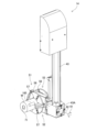
- FIG. 3 is a perspective view of a lifting arm and a head.
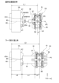
- FIG. 7 is a diagram showing the states of the left spindle device and the head when setting a reference position and transferring a workpiece. The figure which shows the reception screen of a control panel.
- FIG. 7 is a diagram showing the states of the stocker device and the head when setting a reference position and transferring a workpiece.
- FIG. 1 shows a front view of a machine tool 1 of this embodiment.
- FIG. 2 shows a block diagram of the machine tool 1.
- FIG. 3 shows a perspective view of the main body of the machine tool 1 with the device cover 2 (see FIG. 1) removed.
- the Z direction the right direction in the machine width direction and horizontal to the device installation surface
- the Z direction the direction when the machine tool 1 is viewed from the front.
- the front direction parallel to and perpendicular to the Z direction will be referred to as the Y direction
- the Z direction and the upper direction perpendicular to the Y direction will be referred to as the X direction.
- the letter “L” will generally be added to the reference numerals relating to the devices disposed on the left side of the machine tool 1
- the letter “R” will be added to the reference numerals relating to the apparatuses disposed on the right side.
- FIGS. 1 and 2 (Configuration of machine tool 1) As shown in FIGS. 1 and 2, the front surface of the machine tool 1 is covered with a device cover 2, and a movable operation panel 3 is provided on the front surface of the machine.
- the operation panel 3 is movable in the Z direction from the center of the front surface of the device to the right end along a rail 6 provided on the lower right side of the front surface of the device cover 2.
- the device cover 2 is provided with a left front door 5L on the left side of the machine tool 1, and a right front door 5R on the right side.
- the left and right front doors 5L and 5R are, for example, sliding doors, and by opening the doors, it is possible to access the processing space behind the doors.
- the machine tool 1 includes, in addition to the operation panel 3, a left processing device 11L, a right processing device 11R, a stocker device 9, a workpiece transfer device 14, and a control device 15.
- a processing space for a left processing device 11L is provided behind the left front door 5L.
- the left processing device 11L is, for example, a turret-type lathe, and includes a left spindle device 12L and a left turret 13L.
- the left spindle device 12L includes, for example, a plurality of child claws that chuck a workpiece, grips the workpiece with the plurality of child claws, and rotates the workpiece around a main axis parallel to the Z direction.
- the left turret 13L has a tool rest to which a plurality of tools (rotary tools and cutting tools) can be attached, and performs tool indexing.
- the left turret 13L executes machining (cutting, drilling, etc.) on the workpiece gripped by the left spindle device 12L using the indexed tool.
- the user checks the machining state of the workpiece and replaces deteriorated tools through the left front door 5L.
- the right processing device 11R has the same configuration as the left processing device 11L except for the direction of the main axis (device). Therefore, in the description of the right side processing device 11R, description of the same contents as the left side processing device 11L will be omitted.
- a processing space for the right spindle device 12R and the right turret 13R of the right processing device 11R is provided.
- the main axis of the right main spindle device 12R is parallel to the Z direction, and faces (opposes) the main axis of the left main spindle device 12L of the left processing device 11L in the left-right direction. Therefore, the left and right processing devices 11L and 11R are so-called opposed two-axis lathes arranged symmetrically.
- the left and right processing devices 11L and 11R do not have to have a symmetrical configuration. Further, the right processing device 11R may not have the same configuration as the left processing device 11L. For example, at least one of the left processing device 11L and the right processing device 11R may be another type of processing device such as a machining center.
- the machine tool 1 is a multi-tasking machine that has the functions of both an NC lathe and a machining center.
- FIG. 4 is a right side view of the machine tool 1 in the state shown in FIG.
- a tool spindle device 21 is provided approximately at the center of the machine tool 1 in the left-right direction.
- the tool spindle device 21 performs machining that is difficult for the left and right machining devices 11L and 11R, which are lathes.
- the tool spindle device 21 can, for example, perform drilling in addition to lathe processing on the workpieces gripped by the left and right spindle devices 12L and 12R, respectively, and can drill holes at depths that are difficult to perform with the left and right turrets 13L and 13R. This enables workpiece machining at the sheath angle.
- the machine tool 1 includes a multi-tasking machine including left and right processing devices 11L, 11R, and a tool spindle device 21 on one bed 22.
- Each of the left and right spindle devices 12L, 12R rotates the work W (see FIG. 4) based on the drive of spindle motors 14L, 14R provided outside the devices.
- the left and right spindle devices 12L and 12R including the spindle motors 14L and 14R are slidable in a direction parallel to the Z direction along an inclined surface 23 on a bed 22 having a slant bed structure.
- the left and right spindle devices 12L and 12R move in a direction parallel to the Z direction by driving a ball screw mechanism (not shown) by, for example, a Z-axis servo motor 17 (see FIG. 4) provided at the bottom.
- the left and right turrets 13L, 13R and the tool spindle device 21 are both movable in the machine body longitudinal direction and the machine body vertical direction perpendicular to the spindle. For example, while the tool spindle device 21 moves in the horizontal Y direction and the vertical X direction, the left and right turrets 13L and 13R move in the YL direction, which is the Y direction and the It is in the XL direction.
- an automatic tool changer 25 is provided on the front side of the tool spindle device 21.
- the tool spindle device 21 can exchange a tool T (spindle head tool) with an automatic tool changer 25.
- the automatic tool changer 25 is equipped with a tool magazine 25A storing a plurality of tools T at the top of the device, and a tool changer 25B provided at a position facing the tool spindle device 21 exchanges tools T from the tool magazine 25A. , the tool is transported to the tool exchange position of the tool spindle device 21.
- the machine tool 1 can also perform tool exchange in the tool spindle device 21 while machining the workpiece W in each of the left and right machining devices 11L and 11R.
- the machine tool 1 includes, for example, separation shutters (not shown) disposed on both left and right sides of the tool spindle device 21 in the Z direction.
- the machine tool 1 is capable of individually moving two separation shutters in the Y direction by a drive mechanism (not shown).
- FIG. 3 shows a state in which this separation shutter is housed.
- the machine tool 1 separates the machining spaces of the left machining device 11L and the right machining device 11R from the tool exchange space of the tool spindle device 21 by two separation shutters. This makes it possible to prevent each device from being affected by coolant or chips. Further, by closing only one separation shutter, the space including the tool exchange space can be expanded to the machining space for one of the turrets and the tool spindle device 21.
- the work transport device 14 transfers the work W to and from the left and right processing devices 11L, 11R, and each device for carrying in, discharging, inspecting, etc. the work.
- the left and right processing devices 11L, 11R and each device that transfers the workpiece W are examples of counterpart devices of the present disclosure.
- the machine tool 1 includes a stocker device 9 as one of the partner devices. As shown in FIG. 1, the stocker device 9 includes a plurality of pallets 10 on which workpieces W can be stacked, and replaces the pallets 10 at the working position based on the control of the control device 15.
- the workpiece conveyance device 14 receives the workpiece W before processing and delivers the workpiece W after processing to and from the pallet 10 at the working position. Details of the workpiece conveyance device 14 will be described later.
- the operation panel 3 is provided on the front surface of the device cover 2, and includes a touch panel 3A and an operation device 3B.
- the operating device 3B includes, for example, operating switches, push buttons, dials, display lamps, and the like.
- the operation panel 3 receives operation inputs from the user on the touch panel 3A and the operation device 3B, and outputs a signal corresponding to the received operation inputs to the control device 15. Further, the operation panel 3 changes the display content of the touch panel 3A and the lighting state of the display lamp of the operation device 3B based on the control of the control device 15. Furthermore, a pendant 8 for operating the machine tool 1 can be hung below the center of the device cover 2.
- the control device 15 of the machine tool 1 is a processing device mainly composed of a computer, and includes a CPU 15A and a storage device 15B.
- the storage device 15B includes, for example, RAM, ROM, flash memory, and the like.
- the control device 15 is electrically connected to each device (the left processing device 11L, the workpiece transfer device 14, etc.) and can control each device.
- Various control programs 16 are stored in the storage device 15B.
- the control program 16 includes, for example, an NC program that controls the operation of the left and right processing devices 11L and 11R in processing a workpiece, a program that controls the operation of the workpiece conveyance device 14, and a ladder circuit program that processes various signals. It includes programs, etc.
- control program 16 is associated with, for example, the XYZ coordinates of the transfer position where the work transfer device 14 executes the transfer of the workpiece W, the name of the process in which the work is performed at the transfer position, identification information for identifying the process, etc. is memorized.
- the coordinates in each of the XYZ directions will be referred to as the X coordinate, Y coordinate, and Z coordinate. This coordinate system is for convenience of explanation and can be changed as appropriate.
- the setting of each coordinate is not limited to the above-described setting, and for example, the left-right direction (Z direction) may be set as the X coordinate, the front-back direction as the Y coordinate, and the up-down direction (X direction) as the Z coordinate.
- the workpiece conveyance device 14 is, for example, a gantry-type conveyance device, and is capable of moving the gripped workpiece W in three directions, XYZ directions. Note that FIG. 1 illustrates in one figure the state of the workpiece conveyance device 14 that moves to a plurality of positions.
- the machine tool 1 includes a turret-shaped frame structure 31 in which beams are connected to front, rear, left and right columns that are erected to match the width of the bed 22.
- Each device on the bed 22 such as the tool spindle device 21, the automatic tool changer 25, and the workpiece transfer device 14 are covered on the front side by a device cover 2 supported by a frame structure 31.
- the workpiece conveyance device 14 includes a rail stand 32 and a traveling table 33.
- the rail stand 32 is provided on the frame structure 31 and on the front side of the apparatus.
- Two running rails 34 parallel to the Z direction and one running rack 35 are provided on the rail stand 32.
- the traveling table 33 is slidable along the traveling rail 34.
- a traveling motor 37 is fixed to the traveling table 33.
- the traveling table 33 can be moved in the Z direction by a pinion fixed to the rotating shaft of the traveling motor 37 meshing with the traveling rack 35.
- the control device 15 can move the workpiece conveyance device 14 to any position in the Z direction by controlling the travel motor 37.
- a slide table 39 is provided on the top surface of the traveling table 33 so as to be slidable in the Y direction.
- a rack for moving in the Y direction is provided on the side surface of the slide table 39.
- a front and rear motor 41 is fixed to the traveling table 33.
- a pinion fixed to the rotating shaft of the front and rear motor 41 is meshed with a rack of the slide base 39.
- the control device 15 can move the slide base 39 to any position in the Y-axis direction (front-back direction) by controlling the front-back motor 41 .
- the slide table 39 protrudes forward from the frame structure 31, and is provided with an elevating arm 43 that moves up and down at its tip.
- a support column 45 equipped with a lifting rail is fixed to the front end of the slide table 39 in a posture parallel to the X direction.
- a lifting arm 43 is provided in front of the support column 45.
- the lifting arm 43 is movable in the X direction along the lifting rail of the support column 45.
- a lifting motor 47 is provided at the top of the support column 45.
- a pulley is fixed to the rotating shaft of the lifting motor 47.
- a belt is stretched between the pulley of the lifting motor 47 and a pulley pivotally supported at the lower part of the support column 45.
- the lifting arm 43 is connected to the belt, and its position in the X direction is changed according to the driving of the lifting motor 47.
- the control device 15 can change the position of the lifting arm 43 in the X-axis direction (vertical direction) by controlling the lifting motor 47.
- a head 51 for gripping the work W is provided at the lower end 43A of the lifting arm 43. Therefore, the control device 15 can move the head 51 to any position in the XYZ directions by controlling the traveling motor 37, the front-rear motor 41, and the lifting motor 47.
- the head 51 is attached to the rear side surface of the lower end portion 43A, and is arranged at a position on the rear side with respect to the lifting arm 43.
- FIG. 5 shows a perspective view of the lifting arm 43 and head 51.
- the head 51 has two gripping parts, a first gripping part 52 and a second gripping part 53.
- the second grip part 53 has the same configuration as the first grip part 52. Therefore, in the following description, description of the second grip part 53 will be omitted as appropriate.
- the head 51 includes a support member 56, a first claw member 57, and a second claw member 58.
- the support member 56 is attached to the rear of the lower end portion 43A of the lifting arm 43.
- the support member 56 has a substantially rectangular plate shape with a predetermined thickness.
- a first gripping portion 52 and a second gripping portion 53 are provided on each surface of the support member 56 that faces each other in the thickness direction (direction from the left front to the right back in FIG. 5).
- the support member 56 is rotatably attached to the lower end portion 43A.
- the control device 15 rotates the head 51 around a rotation axis 62 (see FIGS.
- the head 51 rotates, for example, in the rotation direction 61 (clockwise or counterclockwise) by 90 degrees in response to the drive of the turning motor.
- the head 51 has a turning position (two turning positions including a 180 degree reversed position) in which each of the first and second gripping parts 52 and 53 is directed to both sides in the Z direction (left and right sides), and a second turning position.
- the first and second gripping parts 52 and 53 are rotated to a total of four rotational positions (two rotational positions including a 180 degree inverted position) in which each of the first and second gripping parts 52 and 53 is directed to both sides in the X direction (both upper and lower sides). do.
- the control device 15 sets the head 51 to the first rotation position RP1.
- the control device 15 controls the first gripping part 52 to face downward.
- the head 51 is rotated to the fourth rotation position RP4.
- the rotation angle and pivot position of the head 51 described above are merely examples.
- the head 51 may be configured to rotate at intervals of an angle larger than 90 degrees (such as 180 degrees), or at intervals of a small angle (such as 45 degrees), or may be configured to rotate at an arbitrary rotation angle.
- three first claw members 57 can be attached to the first grip part 52.
- Each of the three first claw members 57 has, for example, the same shape and is attached at a position shifted by 120 degrees in the circumferential direction.
- the three first claw members 57 are removably attached to the support member 56, and can be replaced with a different type of first claw member 57 depending on the type of work W or the like.
- the three first claw members 57 slide (open and close) in the radial direction in accordance with the drive of a hydraulic cylinder (not shown) provided in the head 51.
- the control device 15 closes the three first claw members 57 to clamp the workpiece W, or opens the three first claw members 57 to release the clamping by driving the hydraulic cylinder.
- the second gripping portion 53 is capable of attaching and detaching, for example, three second claw members 58, and the second claw members 58 can be opened and closed.
- the control device 15 executes processing on the workpiece W based on the control program 16.
- the workpiece W to be processed is transported from the stocker device 9 to the left spindle device 12L and the right spindle device 12L by the workpiece transfer device 14, for example.
- the control device 15 executes predetermined machining using the left and right turrets 13L, 13R and the tool spindle device 21.
- the control device 15 receives the processed workpiece W from the left spindle device 12L or the like to the workpiece transfer device 14, and transfers it to the stocker device 9.
- the XYZ coordinates of the transfer position which is the position of the head 51 that transfers the work W between the work transfer device 14 and each partner device.
- the control device 15 places the head 51 at the delivery position (XYZ coordinates) set in this NC program, turns the head 51 to a predetermined turning position, and transfers the workpiece W between the head 51 and the partner device. do.
- the machine tool 1 of this embodiment is capable of setting a reference position, which is a reference for setting a delivery position, using a contact detection device.
- the control device 15 uses the length of the workpiece W input by the user as an input value, and corrects each delivery position based on a preset reference position and the length of the input value.
- the upper diagram shows the state of the left spindle device 12L and the head 51 when setting the reference position
- the lower diagram shows the state of the left spindle device 12L and the head 51 when the workpiece is transferred.
- a master work 63 is attached to the left spindle device 12L when setting the reference position. This master work 63 is used as a member brought into contact with the contact detection device 65 when setting the reference position P1, and is also used as a member for checking misalignment of the main spindle during centering work of the main spindle.
- the master work 63 includes, for example, a disc-shaped clamped part 63A and a substantially cylindrical convex part 63B protruding from the center of the clamped part 63A. Note that the shape of the master work 63 shown in FIG. 6 is an example.
- the left spindle device 12L is capable of attaching a plurality of (for example, three) child claws 67 that can hold the workpiece W or the master workpiece 63, for example.
- Each of the plurality of child claws 67 has, for example, the same shape, and is attached at a position shifted in the circumferential direction by a predetermined rotation angle (for example, 120 degrees). Further, the plurality of child claws 67 move in the radial direction based on the drive of a drive source (such as a hydraulic cylinder) provided in the left spindle device 12L, and grip the workpiece W and the master workpiece 63.
- a drive source such as a hydraulic cylinder
- the member that holds the workpiece W and the master workpiece 63 is not limited to the claw members such as the child claws 67, but may be other members such as a collet chuck.
- the master work 63 is held between the plurality of child claws 67.
- the user operates the operation panel 3 to open the child claws 67 and seats the master work 63 on the left spindle device 12L.
- the user operates the operation panel 3 to close the sub-claws 67 and causes the sub-claws 67 to clamp the clamped portion 63A of the master work 63.
- the master work 63 is placed in contact with the abutment portion 67A formed on the child pawl 67, and is restricted from moving toward the base end side (left side in FIG. 6) of the left spindle device 12L.
- the centers of the pinched portion 63A and the convex portion 63B are on the main shaft 69. That is, when the master work 63 is placed at the correct position for measurement, movement toward the proximal end is restricted, and the center of rotation is on the main shaft 69.
- the work of placing the master work 63 on the left spindle device 12L may be automatically performed by the head 51 of the work transfer device 14.
- the control device 15 causes the head 51 to grip the master work 63 placed in the stocker device 9, transports the master work 63 to the left spindle device 12L, and transfers the master work 63 from the head 51 to the left spindle device 12L. Masterwork 63 may also be handed over to 12L.
- the user When the user installs the master work 63 on the left spindle device 12L, the user causes the contact detection device 65 to be held by the first gripping portion 52 of the head 51.
- the operation of holding the contact detection device 65 between the heads 51 may be carried out by the user operating the operation panel 3 similarly to the master work 63, or the contact detection device 65 may be placed in the stocker device 9, work station, etc. Alternatively, the head 51 may automatically grab it.
- the first claw member 57 has a different shape when setting the reference position (upper figure) and when transferring the workpiece (lower figure).
- the first claw member 57 is preferably changed to one suitable for holding the contact detection device 65 and the workpiece W, but the same type of first claw member 57 is used when setting the reference position and when transferring the workpiece. It's okay.
- the contact detection device 65 is, for example, a touch probe, and when the tip of the stylus 65A comes into contact with another member, it transmits a contact detection signal indicating the occurrence of contact via wireless communication.
- the control device 15 includes a wireless device 18 that can communicate wirelessly with the contact detection device 65.
- the control device 15 is capable of receiving a contact detection signal SI from the contact detection device 65 held by the first claw member 57 of the head 51 via wireless communication.
- the contact detection method in the contact detection device 65 is not particularly limited, but a movable contact method, a pressure sensor method, an optical sensor method, etc. can be adopted.
- the contact detection device of the present disclosure is not limited to a touch probe, and may use a push button switch having a movable contact or a pressure sensor.
- the method of transmitting the contact detection signal SI to the control device 15 is not limited to wireless communication, but may be a method using infrared rays or electromagnetic induction. Further, the contact detection signal SI may be transmitted by wired communication.
- the control device 15 places the head 51 at a predetermined measurement start position P2 (see FIG. 6).
- This measurement start position P2 is a position where the head 51 is placed when starting measurement of the reference position P1. For example, if the head 51 is placed at the measurement start position P2 in FIG. 6 by performing centering work etc. in advance, the X coordinate in the X direction and the Y coordinate in the Y direction of the head 51 at the measurement start position P2 are This coincides with the XY coordinates of the main axis 69 of 12L.
- the control device 15 brings the stylus 65A of the contact detection device 65 into contact with a plurality of locations on the convex portion 63B of the master work 63 based on the user's operation instruction, detects the center position of the convex portion 63B, The amount of deviation from the main shaft 69 is corrected and centering is performed.
- the control device 15 moves the head 51 in the Z direction and sets the Z coordinate in the Z direction based on the detection by the contact detection device 65.
- the control device 15 can use the XY coordinates of the main axis as the XY coordinates. Therefore, the control device 15 sets the XY coordinates of the main shaft 69 (XY coordinates of the measurement start position P2) determined by performing the centering operation as the XY coordinates of the reference position P1.
- the control device 15 When the head 51 is placed at the measurement start position P2, the control device 15 keeps the XY coordinates constant and moves the head 51 toward the left spindle device 12L along a direction parallel to the Z direction (from the measurement start position P2 in FIG. 6). (see arrow). The control device 15 controls the travel motor 37 to move the head 51 in a direction parallel to the Z direction.
- the contact detection device 65 transmits a contact detection signal SI when the stylus 65A contacts the surface of the convex portion 63B on the head 51 side. Upon acquiring the contact detection signal SI from the contact detection device 65, the control device 15 sets the Z coordinate of the reference position P1.
- the control device 15 corrects the delay time necessary for transmitting the contact detection signal SI from the contact detection device 65 to the control device 15 with respect to the time when the contact detection signal SI is acquired, and Calculate the output time when is output. Then, the control device 15 sets the Z coordinate where the head 51 was placed at the output time as the Z coordinate of the reference position P1.
- the Z coordinate of the head 51 can be detected based on the position information of the traveling motor 37 described above. Note that the control device 15 does not need to perform the above-described transmission time delay correction.
- the control device 15 may set the Z coordinate of the head 51 at the time when the contact detection signal SI is input as the Z coordinate of the reference position P1.
- the control device 15 sets, for example, the distance along the Z direction from the origin position P3 to the reference position P1 shown in FIG. 6 as the reference distance L1.
- This origin position P3 is a reference position (origin) for determining the delivery position.
- the origin position P3 may be set at a position other than the left spindle device 12L (such as a predetermined position on the frame structure 31). That is, the origin position P3 is not limited to the position of the left spindle device 12L, but can be set at any position of the machine tool 1.
- the control device 15 displays on the operation panel 3 that the reference position setting process is completed.
- the user confirms the completion indication, the user removes the contact detection device 65 from the head 51, removes the master work 63 from the left spindle device 12L, and replaces the first claw member 57 with one suitable for the workpiece W to be machined.
- the control device 15 receives the length of the workpiece W to be machined before processing the workpiece W.
- the control device 15 may perform the process of accepting this length as an input value before receiving the processing start instruction.
- the control device 15 displays on the touch panel 3A a reception screen for inputting the length of the workpiece W in response to a predetermined operation input on the touch panel 3A.
- FIG. 7 shows an example of a reception screen 73 for inputting the length of the work W.
- the control device 15 receives information such as the position name, the weight of the workpiece W, the length of the workpiece W, the turning position, and whether or not there is a transfer as input values. Note that the input values shown in FIG. 7 are just an example.
- the control device 15 sets the position names NO1 to NO6 as the names of the delivery positions for these six deliveries, and identifies the delivery positions.
- the head 51 receives the workpiece W from the stocker device 9 to the first gripping section 52 at position number NO1, and transfers the workpiece W from the first gripping section 52 to the left spindle device 12L at position number NO2.
- the head 51 receives the work W after the first machining process from the left spindle device 12L to the first gripping section 52 at NO3, and delivers the work W from the first gripping section 52 to the right spindle device 12R at NO4. Then, the head 51 receives the workpiece W after the second machining process from the right spindle device 12R at NO5, and delivers the workpiece W to the stocker device 9 at NO6.
- input value names 75 for explaining each input value are displayed. Further, below each input value name 75, an input field 76 is provided for inputting each input value for each position name (delivery position).
- the top position name NO1 is a delivery position where the unprocessed workpiece W is delivered from the stocker device 9 to the first gripping section 52. Therefore, the user inputs the weight of the unprocessed work W as the input value weight X1, and inputs the length of the unprocessed work W as the length Y1 in the input field 76. For example, when inputting the weight X2 and length Y2 of No.
- the user inputs the weight X2 that has become lighter and the length Y2 that has become shorter due to the first processing step. Further, the user can input, for example, information on the rotational position of the head 51 for each position name (first to fourth rotational positions RP1 to RP4) and information on whether or not to transfer the workpiece W from the head 51 on the reception screen 73. Enter.
- the control device 15 stores the input value on the reception screen 73 in the storage device 15B, and uses it to correct the delivery position, which will be described later. In this way, the control device 15 receives the length of the workpiece W as an input value for each delivery position.
- the control device 15 discards the information received on the reception screen 73.
- the method for obtaining the weight input value is not limited to the method of inputting it using the operation panel 3 described above, and for example, a setting file in which the input value is written may be read into the control device 15.
- the control device 15 may not accept the length input value on the reception screen 73 in advance, but may accept the length input value after receiving the machining start instruction and before starting the machining.
- the screen configuration of the reception screen 73 in FIG. 7 is an example, and the reception screen 73 does not need to include information such as weight, turning position, and information on whether or not there is a delivery.
- the control device 15 receives the length L2 (see FIG. 6) of the unprocessed workpiece W as the length Y1 of the workpiece W having the position name NO2.
- the user may input, for example, a value on the drawing (design) of the unprocessed workpiece W, or a value obtained by actually measuring the workpiece W before processing.
- the control device 15 uses the received length L2 of the workpiece W to set the delivery position of position name NO2. For example, as shown in the lower diagram of FIG.
- the control device 15 calculates a designed position P5, which is the designed position of the head 51 during delivery, based on the length L2 of the received workpiece W.
- the designed position P5 is, for example, a calculated position taking into consideration the designed length of each member, and does not include an error in the Z direction due to an assembly error of the members.
- the workpiece W transferred from the first gripping part 52 comes into contact with the abutting part 67A of the sub-claws 67 and is seated, and is held between the plural sub-claws 67.
- the XY coordinates of the designed position P5 have been adjusted, for example, by centering work, and therefore are the same coordinates as the reference position P1.
- the distance L4 corresponds to the distance from the origin position P3 to the workpiece W held by the sub-jaw 67 of the left spindle device 12L, and can be set in advance according to the structure of the sub-jaw 67, etc.
- the distance L5 is, for example, the distance from the end of the workpiece W held by the first claw member 57 on the support member 56 side to the center of the head 51, and can be set in advance according to the structure of the head 51 and the like.
- the control device 15 calculates a correction distance L6 that is the difference between the distance L3 and the reference distance L1 calculated at the time of setting the reference position.
- the control device 15 can set the delivery position with the error corrected. Specifically, for example, as shown in FIG. 6, the control device 15 sets a position obtained by adding a correction distance L6 to the reference distance L1 in the Z direction as the Z coordinate of the delivery position P6 of position name No. 2. Correct the Z coordinate with .
- the delivery position P6 is on the right side of the reference position P1, but the positional relationship is changed depending on the length of the contact detection device 65 and the workpiece W.
- the control device 15 sets this transfer position P6 in the NC program, and sets it as the transfer position of position name NO2 for transferring the workpiece W from the first gripping section 52 to the left spindle device 12L. Thereby, it is possible to set the delivery position P6 in which parts assembly errors and the like have been corrected, and the workpiece W can be delivered with high accuracy.
- the control device 15 transfers the workpiece W from the head 51 to the left spindle device 12L using the set transfer position P6. Specifically, when the head 51 holding the work W is placed at the delivery position P6, the control device 15 causes the child claws 67 to grip the work W. After releasing the chuck of the first claw member 57 and retracting the head 51, the control device 15 rotates the left spindle device 12L to start machining.
- the control device 15 of this embodiment sets the reference position P1 using the origin position P3 of the left spindle device 12L as a reference.
- the reference position P1 can be set with high precision by using a predetermined position of the left spindle device 12L, which is the counterpart device, as the origin, and using the measurement result of the contact detection device 65 with the origin as a reference.
- the control device 15 calculates the designed position P5 of the head 51 based on the input length of the workpiece W and the origin position P3 of the left spindle device 12L.
- the control device 15 corrects the delivery position P6 based on the difference (correction distance L6) between the designed position P5 and the reference position P1.
- the corrected distance L6 can be calculated with high accuracy using the reference distance L1, which is an actual measurement value, and the designed distance L3.
- the method for calculating the correction distance L6 is not limited to the method using the origin position P3 described above, but may also be based on the initial position of the workpiece transport device 14, etc., for example.
- the control device 15 uses the contact detection device 65, which is a touch probe, to bring the stylus 65A into contact with the left spindle device 12L (master work 63), and acquires the contact detection signal SI through wireless communication. .
- the control device 15 sets the reference position P1 based on the position of the head 51 at the timing when the contact detection signal SI is output. This eliminates the need for a cable connecting the contact detection device 65 and the control device 15 when the head 51 holds the contact detection device 65 for measurement.
- each machine tool 1 can acquire the contact detection signal SI from the contact detection device 65, and the contact detection device 65 can be reused by the plurality of machine tools 1. can do. It is not necessary to provide the contact detection device 65 in every machine tool 1, and the manufacturing cost of the machine tool 1 can be reduced.
- the control device 15 acquires, as the length L2 of the workpiece W, the length along the spindle 69 of the workpiece W held by the left spindle device 12L as an input value.
- the control device 15 sets a delivery position P6 in the Z direction parallel to the main shaft 69 based on the acquired input value and the reference position P1. Thereby, the error in the delivery position P6 in the direction along the main shaft 69 of the left main shaft device 12L can be corrected using the input value.
- the delivery position with position name No. 2 was explained, but correction can be made in the same way for other delivery positions.
- machining is performed twice, so the length of the workpiece W is the unmachined length Y1, the length after the first machining step Y2, and the second machining step.
- the control device 15 receives the three types of lengths Y1, Y2, and Y3 described above, as shown in the reception screen 73 of FIG.
- the control device 15 sets the reference position P1 and reference distance L1 necessary for other position names No. 1, 3 to 6, as well as the above-mentioned position name No. Execute using Further, as shown in FIG. 7, the control device 15 receives three types of lengths Y1, Y2, and Y3 as input values.
- the control device 15 may accept the length values themselves as input values for the three types of lengths Y1, Y2, and Y3, or may accept the differences in length.
- the control device 15 may receive the unprocessed length Y1 and the length difference that becomes shorter after each processing step.
- the control device 15 uses the unprocessed length Y1 for position names Nos. 1 and 2, uses the length Y2 after the first machining process for position names Nos. 3 and 4, and uses the length Y2 after the first machining process for position names Nos. 5 and 6. Correction is performed using the length Y3 after the second processing step.
- the control device 15 inputs, for example, the length Y1 of the workpiece W before processing as a first input value, and the length Y2 of the workpiece W after processing is completed by the left processing device 11L as a second input value.
- the length Y3 of the workpiece W after the processing is completed by the right processing device 11R is obtained as the third input value.
- the control device 15 sets a transfer position P6 when transferring the workpiece W to the left processing device 11L based on the length Y1. Further, the control device 15 sets the transfer position when transferring the workpiece W to the right processing device 11R based on the length Y2. Further, the control device 15 sets the transfer position when transferring the workpiece W to the stocker device 9 based on the length Y3.
- FIG. 8 shows, as an example, the case where the workpiece W is transferred between the head 51 and the stocker device 9.
- the pallet 10 in FIG. 8 is the pallet 10 placed at the working position of the stocker device 9.
- the pallet 10 of the stocker device 9 is provided with a plurality of positioning pins 10A.
- the work W placed on the upper surface of the pallet 10 is placed with its axial direction aligned with the up-down direction by a plurality of positioning pins 10A.
- the head 51 transfers the workpiece W to and from the pallet 10, for example, at the fourth rotation position RP4 with the first gripping part 52 facing downward.
- the control device 15 corrects the X coordinate in the X direction. As shown in the upper diagram of FIG.
- the control device 15 uses the contact detection device 65 held by the head 51 as a reference in the Set position P1.
- the control device 15 receives, for example, the length of the unprocessed workpiece W (the length Y1 of the position name No. 1 on the reception screen 73) as the length of the workpiece W when the workpiece W is received from the pallet 10 to the head 51. Further, the control device 15 receives the length after the second processing (length Y3 of position name No. 6 on the reception screen 73) as the length to deliver the workpiece W to the pallet 10. Then, the control device 15 calculates the distance L3 in the X direction and the correction distance L6 based on the received lengths Y1 and Y3, and corrects the X coordinate of the delivery position P6 of the position names NO1 and NO6.
- the control device 15 performs various operations such as transferring the unprocessed workpiece W, transferring the processed workpiece W, transferring the workpiece W from the head 51 to the other device, and receiving the workpiece W from the other device to the head 51.
- the delivery position P6 can be set for each case.
- the control device 15 calculates the correction distance L6 and the reference position P1 based on the respective lengths Y1 to Y3, as in the case of FIG. 6 described above. Accordingly, the delivery position P6 can be corrected with high accuracy.
- the user can change the delivery position of each position by changing each length Y1 to Y3.
- the same reference position P1 and reference distance L1 can be used for different types of workpieces W. Even if the types of workpieces W are different, the same reference position P1 can basically be used as long as the distance between the left spindle device 12L and the head 51 varies depending on the length of the workpiece W. For example, the user inputs the length of the workpiece W to be processed next on the reception screen 73 each time a setup change is made to change the workpiece W to be processed.
- the control device 15 sets the transfer position P6 when transferring an arbitrary work W from the head 51 to the partner device, and when setting the transfer position P6 for a work W different in type from the arbitrary work W. , using the same reference position P1.
- the reference position setting process using the contact detection device 65 may be performed every time the setup is changed.
- the stocker device 9 is an example of a counterpart device and a placing stand.
- the left spindle device 12L is an example of a counterpart device, a first spindle device.
- the right spindle device 12R is an example of a counterpart device, a second spindle device.
- the left turret 13L is an example of a first processing device.
- the right turret 13R is an example of a second processing device.
- the work transfer device 14 is an example of a robot.
- the tool spindle device 21 is an example of the first and second processing devices.
- the first claw member 57 and the second claw member 58 are examples of holding members.
- the lengths Y1, Y2, and Y3 are examples of the first input value, the second input value, and the third input value.
- the control device 15 brings the contact detection device 65 held by the head 51 into contact with the left spindle device 12L, and based on the acquisition of the contact detection signal SI of the contact detection device 65, the control device 15 causes the head 51 to A reference position P1 is set. This makes it possible to set the reference position P1 that takes into account errors in assembly accuracy of components such as the head 51. Then, the control device 15 obtains the length L2 of the workpiece W as an input value, and sets a transfer position P6 for transferring the workpiece W from the head 51 to the left spindle device 12L based on the input value and the reference position P1. do. Thereby, there is no need to provide a sensor or the like in the counterpart device, and the delivery position P6 can be set accurately based on the measurement results while simplifying the entire device of the machine tool 1.
- the machine tool 1 may be configured to include (permanently installed) the contact detection device 65.
- the contact detection device 65 may be permanently installed at a stand where the workpiece W is placed or a station where a tool is placed.
- the control device 15 may pick up the contact detection device 65 using the workpiece transport device 14 and perform the measurement when measurement or the like is necessary.
- a contact detection device 165 may be attached to the head 51, as shown by the broken line in FIG.
- the contact detection device 165 may be configured, for example, to be able to extend and retract the stylus 65A, and may be configured to project the stylus 65A further forward than the first claw member 57 during measurement under the control of the control device 15. Further, the contact detection device 165 may have a configuration in which the stylus 65A is housed within the support member 56 when measurement is not performed. In this way, the machine tool 1 may include the contact detection device 165 as a part of the device. Furthermore, the configuration of the head 51 in the above embodiment is merely an example. For example, although the second gripping part 53 has the same structure as the first gripping part 52, it may have a different structure. The number of second claw members 58 may be greater than the number of first claw members 57.
- first and second gripping parts 52 and 53 are provided at positions rotated by 180 degrees, the present invention is not limited thereto.
- the second gripping part 53 may be provided at a position rotated by 90 degrees from the first gripping part 52.
- the head 51 may include only the first gripping portion 52 and may not include the second gripping portion 53.
- the reference position P1 may be set by bringing the contact detection device 65 into contact with the center of the head 51 side surface of the left spindle device 12L (the center surrounded by the plurality of child claws 67, the position on the main spindle 69). . Therefore, in the above embodiment, the master work 63 is used as the member of the partner device with which the contact detection device 65 comes into contact, but the invention is not limited to this. For example, when the left spindle device 12L is provided with a stopper for seating the workpiece W and gripping the workpiece W between it and the child claw 67, the member with which the contact detection device 65 comes into contact may be a stopper.
- the member with which the contact detection device 65 comes into contact may be the main claw.
- the chuck of the left spindle device 12L is a collet chuck
- the member with which the contact detection device 65 comes into contact may be a collet chuck.
- the counterpart devices are not limited to the left and right spindle devices 12L, 12R, and the stocker device 9, but include, for example, a work reversing device that reverses the direction of the work W, and a workpiece W that is placed for the user to check after processing.
- the machine tool 1 may also be a temporary storage stand for discharging workpieces W, or a discharge chute for discharging defective workpieces W.
- the machine tool 1 is equipped with a plurality of partner devices (left and right spindle devices 12L, 12R, stocker device 9) as partner devices of the present disclosure, only one partner device (for example, one main spindle device) is provided. It is also possible to have a configuration with only one).
- the control device 15 may execute the reference position setting process for each type of workpiece W.
- the robot in the present disclosure is not limited to the above-described gantry type loader, but may be an articulated robot.
- the left and right processing devices 11L and 11R are not limited to lathes with two opposing axes, but may be lathes with two parallel axes. Furthermore, various configurations can be adopted as the left and right processing devices 11L and 11R, such as a horizontal lathe, a front lathe, a vertical lathe, a machining center, a milling machine, and a drilling machine.
Abstract
Provided is a machine tool with which a delivery position for delivering a workpiece to a partner device is set on the basis of a measurement result, while achieving a simplified device structure. This machine tool comprises: a contact detection device; a robot that has a holding member and holds a workpiece with the holding member and conveys the workpiece; a partner device that accepts the workpiece from the robot; and a control device. The contact detection device outputs, to the control device, a contact detection signal corresponding to a contact. The control device executes: a reference position setting process that involves controlling the robot and causing the contact detection device to come into contact with the partner device, acquiring, from the contact detection device, a contact detection signal when the contact with the partner device is detected, and setting the position of the robot at the time of contact as a reference position on the basis of the acquisition of the contact detection signal; and a position setting process that involves acquiring the length of the workpiece as an input value and setting a delivery position that is the position of the robot when the workpiece of the input value length is delivered from the robot to the partner device, on the basis of the acquired input value and the reference position.
Description
本開示は、ロボットと相手装置との間でワークの受け渡しを行なう受渡位置を設定する技術に関するものである。
The present disclosure relates to a technology for setting a transfer position for transferring a workpiece between a robot and a partner device.
従来、ワークの受け渡しを行う受渡位置を設定する技術について種々提案されている。例えば、下記特許文献1には、置台との間でワークの受け渡しを実行する産業ロボットについて記載されている。産業ロボットは、多関節ロボットであり、置台に配置されたワークをハンドによって把持して搬送する。置台には、ワークの長さを測定するワーク測定センサが設けられている。産業ロボットは、ワーク測定センサの測定信号を入力し、ワークの長手方向の中心位置を演算し、ハンドによる把持位置を演算した値に基づいて設定する。
Conventionally, various techniques have been proposed for setting the transfer position at which workpieces are transferred. For example, Patent Document 1 listed below describes an industrial robot that transfers a workpiece to and from a table. The industrial robot is an articulated robot that uses its hand to grasp and transport a workpiece placed on a stand. A workpiece measurement sensor that measures the length of the workpiece is provided on the table. The industrial robot inputs the measurement signal of the workpiece measurement sensor, calculates the longitudinal center position of the workpiece, and sets the grasping position of the hand based on the calculated value.
また、上記したワークをロボットに受け取る際だけでなく、ワークをロボットから置台などの相手装置に受け渡す場合にもロボットの位置調整が必要となる。そして、ロボットや相手装置の部品の組み付け精度の誤差などに起因して、ワークの受け渡し制御において受け渡しを精度良く実行できなくなる虞がある。上記した産業ロボットの技術では、ワークを受け取る相手装置のそれぞれにワーク測定センサを設ける必要があり、装置全体が複雑化する虞があった。
Further, the position of the robot needs to be adjusted not only when the above-mentioned workpiece is received by the robot, but also when the workpiece is transferred from the robot to a partner device such as a placing table. Furthermore, due to errors in the accuracy of assembling parts of the robot or the partner device, there is a risk that the workpiece transfer control may not be able to accurately execute the transfer. In the above-mentioned industrial robot technology, it is necessary to provide a workpiece measurement sensor in each partner device that receives a workpiece, which may complicate the entire device.
本開示は、上記の課題に鑑みてなされたものであり、装置の構造の簡素化を図りつつ、相手装置にワークを受け渡す受渡位置を測定結果に基づいて設定できる工作機械を提供することを目的とする。
The present disclosure has been made in view of the above-mentioned problems, and aims to provide a machine tool that can set the delivery position for delivering a workpiece to a partner device based on measurement results while simplifying the structure of the device. purpose.
上記課題を解決するために、本明細書は、接触検出装置と、保持部材を有し、前記保持部材によりワークを保持し前記ワークを搬送するロボットと、前記ロボットから前記ワークを受け取る相手装置と、制御装置と、を備え、前記接触検出装置は、接触に応じた接触検出信号を前記制御装置へ出力し、前記制御装置は、前記ロボットを制御し前記接触検出装置を前記相手装置に接触させ、前記相手装置との接触を検出した際の前記接触検出信号を前記接触検出装置から取得し、前記接触検出信号の取得に基づいて接触時の前記ロボットの位置を基準位置として設定する基準位置設定処理と、前記ワークの長さを入力値として取得し、取得した前記入力値と前記基準位置とに基づいて、前記入力値の長さの前記ワークを前記ロボットから前記相手装置へ受け渡す際の前記ロボットの位置である受渡位置を設定する位置設定処理と、を実行する、工作機械を開示する。
In order to solve the above problems, the present specification provides a contact detection device, a robot that has a holding member and that holds a workpiece with the holding member and transports the workpiece, and a partner device that receives the workpiece from the robot. , a control device, the contact detection device outputs a contact detection signal according to the contact to the control device, and the control device controls the robot to cause the contact detection device to contact the partner device. , a reference position setting for acquiring the contact detection signal from the contact detection device when contact with the partner device is detected, and setting the position of the robot at the time of contact as a reference position based on the acquisition of the contact detection signal; processing, obtaining the length of the workpiece as an input value, and transferring the workpiece having the length of the input value from the robot to the partner device based on the obtained input value and the reference position; A machine tool is disclosed that executes a position setting process for setting a delivery position that is the position of the robot.
また、本明細書は、保持部材を有し、前記保持部材によりワークを保持し前記ワークを搬送するロボットと、前記ロボットから前記ワークを受け取る相手装置と、制御装置と、を備え、前記ロボットは、前記保持部材により接触検出装置を保持可能であり、前記接触検出装置は、接触に応じた接触検出信号を前記制御装置へ出力し、前記制御装置は、前記ロボットの前記保持部材により前記接触検出装置を保持させた状態で前記ロボットを移動させ、前記接触検出装置を前記相手装置に接触させ、前記相手装置との接触を検出した際の前記接触検出信号を前記接触検出装置から取得し、前記接触検出信号の取得に基づいて接触時の前記ロボットの位置を基準位置として設定する基準位置設定処理と、前記ワークの長さを入力値として取得し、取得した前記入力値と前記基準位置とに基づいて、前記入力値の長さの前記ワークを前記ロボットから前記相手装置へ受け渡す際の前記ロボットの位置である受渡位置を設定する位置設定処理と、を実行する、工作機械を開示する。
Further, the present specification includes a robot having a holding member, holding a workpiece by the holding member and transporting the workpiece, a partner device receiving the workpiece from the robot, and a control device, the robot , the contact detection device can be held by the holding member, the contact detection device outputs a contact detection signal according to the contact to the control device, and the control device is capable of holding the contact detection device by the holding member of the robot. moving the robot while holding the device, bringing the contact detection device into contact with the partner device, acquiring the contact detection signal from the contact detection device when contact with the partner device is detected; a reference position setting process of setting the position of the robot at the time of contact as a reference position based on the acquisition of a contact detection signal; and acquiring the length of the workpiece as an input value, and setting the acquired input value and the reference position. Based on the above, a machine tool is disclosed that executes a position setting process for setting a transfer position that is a position of the robot when the workpiece having the length of the input value is transferred from the robot to the partner device.
本開示の工作機械によれば、ロボットの接触検出装置と相手装置を接触させ、接触時の接触検出信号に基づいてロボットの基準位置を設定する。これにより、ロボットや相手装置の部品の組み付け精度の誤差を加味した基準位置を設定することができる。そして、制御装置は、ワークの長さを示す入力値と基準位置とに基づいて、ワークをロボットから相手装置へ受け渡す際の受渡位置を設定する。これにより、相手装置にセンサ等を設ける必要がなく、装置全体の簡素化を図りつつ、受渡位置を測定結果に基づいて精度良く設定できる。
According to the machine tool of the present disclosure, the contact detection device of the robot and the counterpart device are brought into contact, and the reference position of the robot is set based on the contact detection signal at the time of contact. Thereby, it is possible to set a reference position that takes into account errors in assembly accuracy of parts of the robot or the partner device. Then, the control device sets a transfer position for transferring the workpiece from the robot to the partner device, based on the input value indicating the length of the workpiece and the reference position. Thereby, there is no need to provide a sensor or the like in the counterpart device, and the delivery position can be set with high accuracy based on the measurement results while simplifying the entire device.
以下、本開示の工作機械を具体化した一実施例について、図を参照しつつ詳しく説明する。図1は、本実施例の工作機械1の正面図を示している。図2は、工作機械1のブロック図を示している。図3は、工作機械1の装置カバー2(図1参照)を取り外した本体部分の斜視図を示している。以下の説明では、図1に示すように、工作機械1を正面から見た方向を基準として、機械幅方向であって装置の設置面に水平な方向における右方向をZ方向、装置の設置面に平行でZ方向に垂直な前方向をY方向、Z方向及びY方向に垂直な上方向をX方向と称して説明する。また、以下の説明では、概ね、工作機械1の左側に配置された装置に関する符号に「L」の文字を、右側に配置された装置に関する符号に「R」の文字を付加する。
Hereinafter, one embodiment of the machine tool of the present disclosure will be described in detail with reference to the drawings. FIG. 1 shows a front view of a machine tool 1 of this embodiment. FIG. 2 shows a block diagram of the machine tool 1. As shown in FIG. FIG. 3 shows a perspective view of the main body of the machine tool 1 with the device cover 2 (see FIG. 1) removed. In the following explanation, as shown in Fig. 1, the right direction in the machine width direction and horizontal to the device installation surface is referred to as the Z direction, and the direction when the machine tool 1 is viewed from the front is referred to as the Z direction. In the following description, the front direction parallel to and perpendicular to the Z direction will be referred to as the Y direction, and the Z direction and the upper direction perpendicular to the Y direction will be referred to as the X direction. Furthermore, in the following description, the letter "L" will generally be added to the reference numerals relating to the devices disposed on the left side of the machine tool 1, and the letter "R" will be added to the reference numerals relating to the apparatuses disposed on the right side.
(工作機械1の構成)
図1及び図2に示すように、工作機械1は、前面を装置カバー2によって覆われており、機械正面には可動式の操作盤3が設けられている。操作盤3は、装置カバー2の前面における右下に設けられたレール6に沿って、装置前面の中央から右端までZ方向へ移動可能となっている。装置カバー2は、工作機械1の左側に左側正面扉5Lが設けられ、右側に右側正面扉5Rが設けられている。左側及び右側正面扉5L,5Rは、例えば、スライド扉であり、扉を開けることで、扉の後方の加工スペースにアクセス可能となっている。 (Configuration of machine tool 1)
As shown in FIGS. 1 and 2, the front surface of themachine tool 1 is covered with a device cover 2, and a movable operation panel 3 is provided on the front surface of the machine. The operation panel 3 is movable in the Z direction from the center of the front surface of the device to the right end along a rail 6 provided on the lower right side of the front surface of the device cover 2. The device cover 2 is provided with a left front door 5L on the left side of the machine tool 1, and a right front door 5R on the right side. The left and right front doors 5L and 5R are, for example, sliding doors, and by opening the doors, it is possible to access the processing space behind the doors.
図1及び図2に示すように、工作機械1は、前面を装置カバー2によって覆われており、機械正面には可動式の操作盤3が設けられている。操作盤3は、装置カバー2の前面における右下に設けられたレール6に沿って、装置前面の中央から右端までZ方向へ移動可能となっている。装置カバー2は、工作機械1の左側に左側正面扉5Lが設けられ、右側に右側正面扉5Rが設けられている。左側及び右側正面扉5L,5Rは、例えば、スライド扉であり、扉を開けることで、扉の後方の加工スペースにアクセス可能となっている。 (Configuration of machine tool 1)
As shown in FIGS. 1 and 2, the front surface of the
図1~図3に示すように、工作機械1は、操作盤3の他に、左側加工装置11L、右側加工装置11R、ストッカ装置9、ワーク搬送装置14、制御装置15を備えている。左側正面扉5Lの後方には、左側加工装置11Lの加工スペースが設けられている。左側加工装置11Lは、例えば、タレット型の旋盤であり、左側主軸装置12Lと、左側タレット13Lを備えている。左側主軸装置12Lは、例えば、ワークをチャックする複数の子爪を備え、複数の子爪によってワークを把持し、Z方向と平行な主軸を中心にワークを回転させる。左側タレット13Lは、複数の工具(回転工具や切削工具)を取り付け可能な刃物台を有し、工具の割り出しを実行する。左側タレット13Lは、割り出した工具によって左側主軸装置12Lに把持されたワークに対する加工(切削加工や穴開け加工など)を実行する。ユーザは、左側正面扉5Lを介してワークの加工状態の確認や劣化した工具の交換などを実行する。
As shown in FIGS. 1 to 3, the machine tool 1 includes, in addition to the operation panel 3, a left processing device 11L, a right processing device 11R, a stocker device 9, a workpiece transfer device 14, and a control device 15. A processing space for a left processing device 11L is provided behind the left front door 5L. The left processing device 11L is, for example, a turret-type lathe, and includes a left spindle device 12L and a left turret 13L. The left spindle device 12L includes, for example, a plurality of child claws that chuck a workpiece, grips the workpiece with the plurality of child claws, and rotates the workpiece around a main axis parallel to the Z direction. The left turret 13L has a tool rest to which a plurality of tools (rotary tools and cutting tools) can be attached, and performs tool indexing. The left turret 13L executes machining (cutting, drilling, etc.) on the workpiece gripped by the left spindle device 12L using the indexed tool. The user checks the machining state of the workpiece and replaces deteriorated tools through the left front door 5L.
右側加工装置11Rは、主軸(装置)の向きを除いて、左側加工装置11Lと同一の構成となっている。このため、右側加工装置11Rの説明において左側加工装置11Lと同様の内容についての説明を省略する。右側正面扉5Rの後方には、右側加工装置11Rの右側主軸装置12R及び右側タレット13Rの加工スペースが設けられている。右側主軸装置12Rの主軸は、Z方向と平行であり、左側加工装置11Lの左側主軸装置12Lの主軸と左右方向で対向している(向き合っている)。従って、左側及び右側加工装置11L,11Rは、左右対称に配置された所謂、対向2軸型の旋盤である。尚、左側及び右側加工装置11L,11Rは、左右対称な構成でなくとも良い。また、右側加工装置11Rは、左側加工装置11Lと同一構成でなくとも良い。例えば、左側加工装置11L及び右側加工装置11Rの少なくとも一方が、マシニングセンタなどの他の種類の加工装置でも良い。
The right processing device 11R has the same configuration as the left processing device 11L except for the direction of the main axis (device). Therefore, in the description of the right side processing device 11R, description of the same contents as the left side processing device 11L will be omitted. Behind the right front door 5R, a processing space for the right spindle device 12R and the right turret 13R of the right processing device 11R is provided. The main axis of the right main spindle device 12R is parallel to the Z direction, and faces (opposes) the main axis of the left main spindle device 12L of the left processing device 11L in the left-right direction. Therefore, the left and right processing devices 11L and 11R are so-called opposed two-axis lathes arranged symmetrically. Note that the left and right processing devices 11L and 11R do not have to have a symmetrical configuration. Further, the right processing device 11R may not have the same configuration as the left processing device 11L. For example, at least one of the left processing device 11L and the right processing device 11R may be another type of processing device such as a machining center.
また、工作機械1は、NC旋盤とマシニングセンタの両方の機能を備えた複合加工機である。図4は、図3の状態における工作機械1の右側面図である。図2~図4に示すように、左右方向における工作機械1の略中央には、工具主軸装置21が設けられている。工具主軸装置21は、旋盤である左側及び右側加工装置11L,11Rでは難しい加工を実行する。工具主軸装置21は、例えば、左側及び右側主軸装置12L,12Rのそれぞれに把持されたワークに対し旋盤加工の他にも穴あけ加工などをすることができ、左側及び右側タレット13L,13Rでは難しい深さや角度でのワーク加工を可能にするものである。
Furthermore, the machine tool 1 is a multi-tasking machine that has the functions of both an NC lathe and a machining center. FIG. 4 is a right side view of the machine tool 1 in the state shown in FIG. As shown in FIGS. 2 to 4, a tool spindle device 21 is provided approximately at the center of the machine tool 1 in the left-right direction. The tool spindle device 21 performs machining that is difficult for the left and right machining devices 11L and 11R, which are lathes. The tool spindle device 21 can, for example, perform drilling in addition to lathe processing on the workpieces gripped by the left and right spindle devices 12L and 12R, respectively, and can drill holes at depths that are difficult to perform with the left and right turrets 13L and 13R. This enables workpiece machining at the sheath angle.
工作機械1は、左側及び右側加工装置11L,11R、及び工具主軸装置21を備える複合加工機を一つのベッド22の上に備えている。左側及び右側主軸装置12L,12Rの各々は、装置の外側に設けられたスピンドルモータ14L,14Rの駆動に基づいてワークW(図4参照)を回転させる。また、スピンドルモータ14L,14Rを含む左側及び右側主軸装置12L,12Rは、スラントベッド構造のベッド22の上の傾斜面23に沿ってZ方向と平行な方向にスライド移動可能となっている。左側及び右側主軸装置12L,12Rは、例えば、下部に設けられたZ軸サーボモータ17(図4参照)によりボールネジ機構(図示略)を駆動させ、Z方向と平行な方向に移動する。左側及び右側タレット13L,13Rと工具主軸装置21は、何れも主軸と直交する機体前後方向と機体上下方向に移動可能となっている。例えば、工具主軸装置21の移動方向が水平なY方向と鉛直なX方向であるのに対し、左側及び右側タレット13L,13Rの移動方向は、Y方向及びX方向を45度傾けたYL方向とXL方向となっている。
The machine tool 1 includes a multi-tasking machine including left and right processing devices 11L, 11R, and a tool spindle device 21 on one bed 22. Each of the left and right spindle devices 12L, 12R rotates the work W (see FIG. 4) based on the drive of spindle motors 14L, 14R provided outside the devices. Further, the left and right spindle devices 12L and 12R including the spindle motors 14L and 14R are slidable in a direction parallel to the Z direction along an inclined surface 23 on a bed 22 having a slant bed structure. The left and right spindle devices 12L and 12R move in a direction parallel to the Z direction by driving a ball screw mechanism (not shown) by, for example, a Z-axis servo motor 17 (see FIG. 4) provided at the bottom. The left and right turrets 13L, 13R and the tool spindle device 21 are both movable in the machine body longitudinal direction and the machine body vertical direction perpendicular to the spindle. For example, while the tool spindle device 21 moves in the horizontal Y direction and the vertical X direction, the left and right turrets 13L and 13R move in the YL direction, which is the Y direction and the It is in the XL direction.
また、工具主軸装置21の前方側には、自動工具交換装置25が設けられている。工具主軸装置21は、自動工具交換装置25との間で工具T(主軸ヘッド工具)を取り替え可能となっている。自動工具交換装置25は、複数の工具Tを収納したツールマガジン25Aを装置上部に備え、工具主軸装置21と向かい合った位置に設けられたツールチェンジャ25Bによって、ツールマガジン25Aから交換用の工具Tを、工具主軸装置21の工具交換位置まで搬送する。工作機械1は、左側及び右側加工装置11L,11Rの各々でワークWの加工を実行中に、工具主軸装置21の工具交換も実行できる。工作機械1は、例えば、Z方向における工具主軸装置21の左右両側にそれぞれ配置された分離シャッタ(図示略)を備えている。工作機械1は、駆動機構(図示略)によってY方向に2枚の分離シャッタを個別に移動可能となっている。図3は、この分離シャッタを収納した状態を示している。工作機械1は、2枚の分離シャッタにより、左側加工装置11L、右側加工装置11Rの各々の加工スペースと、工具主軸装置21の工具交換スペースを分離する。これにより、各装置がクーラントや切屑の影響を受けないようにすることができる。また、一方の分離シャッタだけを閉じることにより、工具交換スペースを含めた空間を一方のタレットや工具主軸装置21の加工スペースに拡張することもできる。
Furthermore, an automatic tool changer 25 is provided on the front side of the tool spindle device 21. The tool spindle device 21 can exchange a tool T (spindle head tool) with an automatic tool changer 25. The automatic tool changer 25 is equipped with a tool magazine 25A storing a plurality of tools T at the top of the device, and a tool changer 25B provided at a position facing the tool spindle device 21 exchanges tools T from the tool magazine 25A. , the tool is transported to the tool exchange position of the tool spindle device 21. The machine tool 1 can also perform tool exchange in the tool spindle device 21 while machining the workpiece W in each of the left and right machining devices 11L and 11R. The machine tool 1 includes, for example, separation shutters (not shown) disposed on both left and right sides of the tool spindle device 21 in the Z direction. The machine tool 1 is capable of individually moving two separation shutters in the Y direction by a drive mechanism (not shown). FIG. 3 shows a state in which this separation shutter is housed. The machine tool 1 separates the machining spaces of the left machining device 11L and the right machining device 11R from the tool exchange space of the tool spindle device 21 by two separation shutters. This makes it possible to prevent each device from being affected by coolant or chips. Further, by closing only one separation shutter, the space including the tool exchange space can be expanded to the machining space for one of the turrets and the tool spindle device 21.
ワーク搬送装置14は、左側及び右側加工装置11L,11Rや、ワークの搬入、排出、検査等を行なうための各装置との間でワークWの受け渡しを実行する。この左側及び右側加工装置11L,11Rや、ワークWの受け渡しを実行する各装置は、本開示の相手装置の一例である。工作機械1は、相手装置の1つとして、ストッカ装置9を備えている。図1に示すように、ストッカ装置9は、ワークWを積み上げ可能な複数のパレット10を備え、制御装置15の制御に基づいて作業位置のパレット10を入れ替える。ワーク搬送装置14は、作業位置のパレット10との間で、加工前のワークWの受け取りや加工後のワークWの受け渡しを実行する。ワーク搬送装置14の詳細については後述する。
The work transport device 14 transfers the work W to and from the left and right processing devices 11L, 11R, and each device for carrying in, discharging, inspecting, etc. the work. The left and right processing devices 11L, 11R and each device that transfers the workpiece W are examples of counterpart devices of the present disclosure. The machine tool 1 includes a stocker device 9 as one of the partner devices. As shown in FIG. 1, the stocker device 9 includes a plurality of pallets 10 on which workpieces W can be stacked, and replaces the pallets 10 at the working position based on the control of the control device 15. The workpiece conveyance device 14 receives the workpiece W before processing and delivers the workpiece W after processing to and from the pallet 10 at the working position. Details of the workpiece conveyance device 14 will be described later.
また、図1及び図2に示すように、操作盤3は、装置カバー2の前面に設けられ、タッチパネル3Aや操作装置3Bを備えている。操作装置3Bは、例えば、操作スイッチ、押しボタン、ダイヤル、表示ランプ等を備えている。操作盤3は、タッチパネル3Aや操作装置3Bに対する操作入力をユーザから受け付け、受け付けた操作入力に応じた信号を制御装置15に出力する。また、操作盤3は、制御装置15の制御に基づいてタッチパネル3Aの表示内容や操作装置3Bの表示ランプの点灯状態を変更する。また、装置カバー2の中央の下方には、工作機械1を操作するペンダント8が吊り下げ可能となっている。
Further, as shown in FIGS. 1 and 2, the operation panel 3 is provided on the front surface of the device cover 2, and includes a touch panel 3A and an operation device 3B. The operating device 3B includes, for example, operating switches, push buttons, dials, display lamps, and the like. The operation panel 3 receives operation inputs from the user on the touch panel 3A and the operation device 3B, and outputs a signal corresponding to the received operation inputs to the control device 15. Further, the operation panel 3 changes the display content of the touch panel 3A and the lighting state of the display lamp of the operation device 3B based on the control of the control device 15. Furthermore, a pendant 8 for operating the machine tool 1 can be hung below the center of the device cover 2.
また、図2に示すように、工作機械1の制御装置15は、CPU15Aと、記憶装置15Bを備え、コンピュータを主体とする処理装置である。記憶装置15Bは、例えば、RAM、ROM、フラッシュメモリ等を備える。制御装置15は、各装置(左側加工装置11Lやワーク搬送装置14等)と電気的に接続され、各装置を制御可能となっている。記憶装置15Bには、各種の制御プログラム16が記憶されている。制御プログラム16には、例えば、ワークに対する加工において左側及び右側加工装置11L,11Rの各々の動作を制御するNCプログラム、ワーク搬送装置14の動作を制御するプログラム、各種の信号を処理するラダー回路用のプログラム等が含まれている。また、制御プログラム16には、例えば、ワーク搬送装置14がワークWの受け渡しを実行する受渡位置のXYZ座標、その受渡位置で作業を行なう工程名、その工程を識別するための識別情報等が関連付けて記憶されている。尚、以下の説明では、XYZの各方向の座標をX座標、Y座標、Z座標と称して説明する。この座標系は、説明の便宜上であり適宜変更可能である。各座標の設定は、上記した設定に限らず、例えば、左右方向(Z方向)をX座標、前後方向をY座標、上下方向(X方向)をZ座標として設定しても良い。
Further, as shown in FIG. 2, the control device 15 of the machine tool 1 is a processing device mainly composed of a computer, and includes a CPU 15A and a storage device 15B. The storage device 15B includes, for example, RAM, ROM, flash memory, and the like. The control device 15 is electrically connected to each device (the left processing device 11L, the workpiece transfer device 14, etc.) and can control each device. Various control programs 16 are stored in the storage device 15B. The control program 16 includes, for example, an NC program that controls the operation of the left and right processing devices 11L and 11R in processing a workpiece, a program that controls the operation of the workpiece conveyance device 14, and a ladder circuit program that processes various signals. It includes programs, etc. In addition, the control program 16 is associated with, for example, the XYZ coordinates of the transfer position where the work transfer device 14 executes the transfer of the workpiece W, the name of the process in which the work is performed at the transfer position, identification information for identifying the process, etc. is memorized. In the following description, the coordinates in each of the XYZ directions will be referred to as the X coordinate, Y coordinate, and Z coordinate. This coordinate system is for convenience of explanation and can be changed as appropriate. The setting of each coordinate is not limited to the above-described setting, and for example, the left-right direction (Z direction) may be set as the X coordinate, the front-back direction as the Y coordinate, and the up-down direction (X direction) as the Z coordinate.
(ワーク搬送装置14について)
次に、ワーク搬送装置14の詳細について説明する。図1、図3、図4に示すように、ワーク搬送装置14は、例えば、ガントリ式の搬送装置であり、把持したワークWをXYZ方向の3方向に移動可能となっている。尚、図1は、複数の位置に移動するワーク搬送装置14の様子を1つの図の中に図示している。 (About the workpiece conveyance device 14)
Next, details of theworkpiece conveyance device 14 will be explained. As shown in FIGS. 1, 3, and 4, the workpiece conveyance device 14 is, for example, a gantry-type conveyance device, and is capable of moving the gripped workpiece W in three directions, XYZ directions. Note that FIG. 1 illustrates in one figure the state of the workpiece conveyance device 14 that moves to a plurality of positions.
次に、ワーク搬送装置14の詳細について説明する。図1、図3、図4に示すように、ワーク搬送装置14は、例えば、ガントリ式の搬送装置であり、把持したワークWをXYZ方向の3方向に移動可能となっている。尚、図1は、複数の位置に移動するワーク搬送装置14の様子を1つの図の中に図示している。 (About the workpiece conveyance device 14)
Next, details of the
工作機械1は、ベッド22の幅に合わせて立てられた前後左右の柱に前後左右に梁が接続された櫓型のフレーム構体31を備えている。工具主軸装置21などのベッド22上の各装置や自動工具交換装置25及びワーク搬送装置14は、フレーム構体31に支持された装置カバー2によって前面側を覆われている。また、図3及び図4に示すように、ワーク搬送装置14は、レール台32と、走行テーブル33を備えている。レール台32は、フレーム構体31の上であって、装置前方側に設けられている。レール台32の上には、Z方向と平行な2本の走行レール34と、1本の走行用ラック35が設けられている。走行テーブル33は、走行レール34に沿って摺動可能となっている。走行テーブル33には走行用モータ37が固定されている。走行テーブル33は、走行用モータ37の回転軸に固定されたピニオンが走行用ラック35と噛合することによりZ方向の移動が可能になっている。制御装置15は、走行用モータ37を制御することで、ワーク搬送装置14をZ方向の任意の位置に移動させることができる。
The machine tool 1 includes a turret-shaped frame structure 31 in which beams are connected to front, rear, left and right columns that are erected to match the width of the bed 22. Each device on the bed 22 such as the tool spindle device 21, the automatic tool changer 25, and the workpiece transfer device 14 are covered on the front side by a device cover 2 supported by a frame structure 31. Further, as shown in FIGS. 3 and 4, the workpiece conveyance device 14 includes a rail stand 32 and a traveling table 33. The rail stand 32 is provided on the frame structure 31 and on the front side of the apparatus. Two running rails 34 parallel to the Z direction and one running rack 35 are provided on the rail stand 32. The traveling table 33 is slidable along the traveling rail 34. A traveling motor 37 is fixed to the traveling table 33. The traveling table 33 can be moved in the Z direction by a pinion fixed to the rotating shaft of the traveling motor 37 meshing with the traveling rack 35. The control device 15 can move the workpiece conveyance device 14 to any position in the Z direction by controlling the travel motor 37.
走行テーブル33の上面には、スライド台39がY方向にスライド移動可能に設けられている。スライド台39の側面には、Y方向に移動するためのラックが設けられている。走行テーブル33には、前後モータ41が固定されている。前後モータ41の回転軸に固定したピニオンはスライド台39のラックに噛合されている。制御装置15は、前後モータ41を制御することで、Y軸方向(前後方向)の任意の位置にスライド台39を移動させることができる。スライド台39は、フレーム構体31から前方へと突き出しており、その先端部分において上下移動する昇降アーム43が設けられている。
A slide table 39 is provided on the top surface of the traveling table 33 so as to be slidable in the Y direction. A rack for moving in the Y direction is provided on the side surface of the slide table 39. A front and rear motor 41 is fixed to the traveling table 33. A pinion fixed to the rotating shaft of the front and rear motor 41 is meshed with a rack of the slide base 39. The control device 15 can move the slide base 39 to any position in the Y-axis direction (front-back direction) by controlling the front-back motor 41 . The slide table 39 protrudes forward from the frame structure 31, and is provided with an elevating arm 43 that moves up and down at its tip.
スライド台39の前端部には、昇降用レールを備えた支持柱45がX方向と平行な姿勢で固定されている。支持柱45の前方には、昇降アーム43が設けられている。昇降アーム43は、支持柱45の昇降用レールに沿ってX方向へ移動可能となっている。支持柱45の頂部には昇降用モータ47が設けられている。昇降用モータ47の回転軸にはプーリが固定されている。昇降用モータ47のプーリは、支持柱45の下部に軸支されたプーリとの間にベルトが掛け渡されている。昇降アーム43は、そのベルトに連結され、昇降用モータ47の駆動に応じてX方向の位置を変更される。制御装置15は、昇降用モータ47を制御することで、X軸方向(上下方向)における昇降アーム43の位置を変更できる。昇降アーム43の下端部43Aには、ワークWを把持するヘッド51が設けられている。従って、制御装置15は、走行用モータ37、前後モータ41、昇降用モータ47を制御することで、XYZ方向の任意の位置にヘッド51を移動させることができる。
A support column 45 equipped with a lifting rail is fixed to the front end of the slide table 39 in a posture parallel to the X direction. A lifting arm 43 is provided in front of the support column 45. The lifting arm 43 is movable in the X direction along the lifting rail of the support column 45. A lifting motor 47 is provided at the top of the support column 45. A pulley is fixed to the rotating shaft of the lifting motor 47. A belt is stretched between the pulley of the lifting motor 47 and a pulley pivotally supported at the lower part of the support column 45. The lifting arm 43 is connected to the belt, and its position in the X direction is changed according to the driving of the lifting motor 47. The control device 15 can change the position of the lifting arm 43 in the X-axis direction (vertical direction) by controlling the lifting motor 47. A head 51 for gripping the work W is provided at the lower end 43A of the lifting arm 43. Therefore, the control device 15 can move the head 51 to any position in the XYZ directions by controlling the traveling motor 37, the front-rear motor 41, and the lifting motor 47.
ヘッド51は、下端部43Aの後方側の面に取り付けられ、昇降アーム43に対して後方側となる位置に配置されている。図5は、昇降アーム43及びヘッド51の斜視図を示している。ヘッド51は、第1把持部52と第2把持部53の2つの把持部を有している。第2把持部53は、第1把持部52と同一構成となっている。このため、以下の説明では、第2把持部53についての説明を適宜省略する。
The head 51 is attached to the rear side surface of the lower end portion 43A, and is arranged at a position on the rear side with respect to the lifting arm 43. FIG. 5 shows a perspective view of the lifting arm 43 and head 51. The head 51 has two gripping parts, a first gripping part 52 and a second gripping part 53. The second grip part 53 has the same configuration as the first grip part 52. Therefore, in the following description, description of the second grip part 53 will be omitted as appropriate.
図5に示すように、ヘッド51は、支持部材56、第1爪部材57、第2爪部材58を備えている。支持部材56は、昇降アーム43の下端部43Aの後方に取り付けられている。支持部材56は、所定の厚さを有する略長方形の板状をなしている。厚さ方向(図5における左手前から右奥に向かう方向)で対向する支持部材56の各面には、第1把持部52及び第2把持部53がそれぞれ設けられている。支持部材56は、下端部43Aに対して回転可能に取り付けられている。制御装置15は、例えば、下端部43Aの中に設けられた旋回用モータ(図示略)を駆動することで、Y方向と平行な回転軸62(図4、図5参照)を中心にヘッド51を回転させる。これにより、支持部材56は、回転方向61(図4、図5参照)へ回転し、第1及び第2把持部52,53を異なる方向に向ける。
As shown in FIG. 5, the head 51 includes a support member 56, a first claw member 57, and a second claw member 58. The support member 56 is attached to the rear of the lower end portion 43A of the lifting arm 43. The support member 56 has a substantially rectangular plate shape with a predetermined thickness. A first gripping portion 52 and a second gripping portion 53 are provided on each surface of the support member 56 that faces each other in the thickness direction (direction from the left front to the right back in FIG. 5). The support member 56 is rotatably attached to the lower end portion 43A. For example, the control device 15 rotates the head 51 around a rotation axis 62 (see FIGS. 4 and 5) parallel to the Y direction by driving a turning motor (not shown) provided in the lower end portion 43A. Rotate. As a result, the support member 56 rotates in the rotation direction 61 (see FIGS. 4 and 5), and the first and second gripping parts 52 and 53 are oriented in different directions.
ヘッド51は、例えば、旋回用モータの駆動に応じて90度ずつ回転方向61へ(時計回り又は反時計回りの方向へ)回転する。ヘッド51は、第1及び第2把持部52,53の各々をZ方向の両側(左右両側)に向けた状態となる旋回位置(180度反転した位置を含めて2つの旋回位置)と、第1及び第2把持部52,53の各々をX方向の両側(上下両側)に向けた状態となる旋回位置(180度反転した位置を含めて2つの旋回位置)の合計4つの旋回位置に回転する。以下の説明では、第1把持部52を左、上、右、下のそれぞれに向けた旋回位置を、第1~第4旋回位置RP1~RP4と称する。制御装置15は、例えば、後述する図6のように第1把持部52と左側主軸装置12Lとの間でワークWの受け渡しを実行する場合、ヘッド51を第1旋回位置RP1とする。また、制御装置15は、例えば、後述する図8に示すように、第1把持部52とストッカ装置9との間でワークWの受け渡しを実行する場合、第1把持部52を下に向けた第4旋回位置RP4までヘッド51を回転させる。尚、上記したヘッド51の回転角度や旋回位置は一例である。例えば、ヘッド51は、90度よりも大きい角度(180度など)の間隔や、小さい角度(45度など)の間隔で回転する構成でも良く、任意の回転角度に回転する構成でも良い。
The head 51 rotates, for example, in the rotation direction 61 (clockwise or counterclockwise) by 90 degrees in response to the drive of the turning motor. The head 51 has a turning position (two turning positions including a 180 degree reversed position) in which each of the first and second gripping parts 52 and 53 is directed to both sides in the Z direction (left and right sides), and a second turning position. The first and second gripping parts 52 and 53 are rotated to a total of four rotational positions (two rotational positions including a 180 degree inverted position) in which each of the first and second gripping parts 52 and 53 is directed to both sides in the X direction (both upper and lower sides). do. In the following description, the turning positions in which the first gripping part 52 is directed left, upward, right, and downward are referred to as first to fourth turning positions RP1 to RP4. For example, when transferring the workpiece W between the first gripping section 52 and the left spindle device 12L as shown in FIG. 6, which will be described later, the control device 15 sets the head 51 to the first rotation position RP1. In addition, for example, as shown in FIG. 8, which will be described later, when transferring the workpiece W between the first gripping part 52 and the stocker device 9, the control device 15 controls the first gripping part 52 to face downward. The head 51 is rotated to the fourth rotation position RP4. It should be noted that the rotation angle and pivot position of the head 51 described above are merely examples. For example, the head 51 may be configured to rotate at intervals of an angle larger than 90 degrees (such as 180 degrees), or at intervals of a small angle (such as 45 degrees), or may be configured to rotate at an arbitrary rotation angle.
第1把持部52には、例えば、3つの第1爪部材57を取り付け可能となっている。3つの第1爪部材57の各々は、例えば、同一形状をなし、120度だけ周方向にずれた位置に取り付けられている。3つの第1爪部材57は、支持部材56に対して着脱可能に設けられ、ワークWの種類等に応じて異なる種類の第1爪部材57に交換可能となっている。また、3つの第1爪部材57は、ヘッド51に設けられた油圧シリンダ(図示略)の駆動に応じて半径方向へスライド移動する(開閉する)。これにより、制御装置15は、油圧シリンダを駆動することで、3つの第1爪部材57を閉じてワークWを挟持する、あるいは3つの第1爪部材57を開いて挟持を解除する。同様に、第2把持部53は、例えば、3つの第2爪部材58を着脱可能であり、第2爪部材58を開閉可能となっている。
For example, three first claw members 57 can be attached to the first grip part 52. Each of the three first claw members 57 has, for example, the same shape and is attached at a position shifted by 120 degrees in the circumferential direction. The three first claw members 57 are removably attached to the support member 56, and can be replaced with a different type of first claw member 57 depending on the type of work W or the like. Further, the three first claw members 57 slide (open and close) in the radial direction in accordance with the drive of a hydraulic cylinder (not shown) provided in the head 51. Thereby, the control device 15 closes the three first claw members 57 to clamp the workpiece W, or opens the three first claw members 57 to release the clamping by driving the hydraulic cylinder. Similarly, the second gripping portion 53 is capable of attaching and detaching, for example, three second claw members 58, and the second claw members 58 can be opened and closed.
(基準位置設定処理について)
次に、ヘッド51の基準位置の設定処理について説明する。制御装置15は、制御プログラム16に基づいて、ワークWに対する加工を実行する。加工対象となるワークWは、例えば、ワーク搬送装置14によってストッカ装置9から左側主軸装置12Lや右側主軸装置12Lへ搬送される。制御装置15は、ワークWを各主軸装置に受け渡した後、左側及び右側タレット13L,13Rや工具主軸装置21による所定の加工を実行する。制御装置15は、加工が完了したワークWを、左側主軸装置12L等からワーク搬送装置14に受け取り、ストッカ装置9へ搬送する。 (About reference position setting process)
Next, a process for setting the reference position of thehead 51 will be explained. The control device 15 executes processing on the workpiece W based on the control program 16. The workpiece W to be processed is transported from the stocker device 9 to the left spindle device 12L and the right spindle device 12L by the workpiece transfer device 14, for example. After delivering the workpiece W to each spindle device, the control device 15 executes predetermined machining using the left and right turrets 13L, 13R and the tool spindle device 21. The control device 15 receives the processed workpiece W from the left spindle device 12L or the like to the workpiece transfer device 14, and transfers it to the stocker device 9.
次に、ヘッド51の基準位置の設定処理について説明する。制御装置15は、制御プログラム16に基づいて、ワークWに対する加工を実行する。加工対象となるワークWは、例えば、ワーク搬送装置14によってストッカ装置9から左側主軸装置12Lや右側主軸装置12Lへ搬送される。制御装置15は、ワークWを各主軸装置に受け渡した後、左側及び右側タレット13L,13Rや工具主軸装置21による所定の加工を実行する。制御装置15は、加工が完了したワークWを、左側主軸装置12L等からワーク搬送装置14に受け取り、ストッカ装置9へ搬送する。 (About reference position setting process)
Next, a process for setting the reference position of the
例えば、制御プログラム16のNCプログラムには、上記したワーク搬送装置14と各相手装置との間でワークWの受け渡しを行うヘッド51の位置である受渡位置のXYZ座標が設定されている。制御装置15は、このNCプログラムに設定された受渡位置(XYZ座標)にヘッド51を配置するとともにヘッド51を所定の旋回位置に旋回させ、ヘッド51と相手装置の間でワークWの受け渡しを実行する。そして、本実施例の工作機械1は、受渡位置を設定するための基準となる基準位置を、接触検出装置を用いて設定可能となっている。制御装置15は、ユーザから入力されたワークWの長さを入力値として、予め設定した基準位置と入力値の長さに基づいて各受渡位置を補正する。以下の説明では、一例として、相手装置として左側主軸装置12Lを採用し、ヘッド51の第1把持部52から左側主軸装置12LへワークWを受け渡す場合について説明する。尚、図8で後述するように、他の受渡位置についても同様に設定等を実施できる。
For example, in the NC program of the control program 16, the XYZ coordinates of the transfer position, which is the position of the head 51 that transfers the work W between the work transfer device 14 and each partner device, are set. The control device 15 places the head 51 at the delivery position (XYZ coordinates) set in this NC program, turns the head 51 to a predetermined turning position, and transfers the workpiece W between the head 51 and the partner device. do. The machine tool 1 of this embodiment is capable of setting a reference position, which is a reference for setting a delivery position, using a contact detection device. The control device 15 uses the length of the workpiece W input by the user as an input value, and corrects each delivery position based on a preset reference position and the length of the input value. In the following description, as an example, a case will be described in which the left spindle device 12L is employed as a partner device and the workpiece W is transferred from the first gripping portion 52 of the head 51 to the left spindle device 12L. Note that, as will be described later with reference to FIG. 8, settings etc. can be similarly performed for other delivery positions.
図6は、上図が基準位置設定時における左側主軸装置12Lとヘッド51の状態を示しており、下図がワーク受け渡し時における左側主軸装置12Lとヘッド51の状態を示している。図6の上図に示すように、基準位置設定時において、左側主軸装置12Lには、マスターワーク63を装着する。このマスターワーク63は、基準位置P1を設定する際に接触検出装置65と接触させる部材として用いられ、主軸の芯出し作業において主軸のズレを確認するための部材としても用いられるものである。マスターワーク63は、例えば、円盤形状の被挟持部63Aと、被挟持部63Aの中心から突出する略円柱形状の凸状部63Bとを有している。尚、図6に示すマスターワーク63の形状は、一例である。
In FIG. 6, the upper diagram shows the state of the left spindle device 12L and the head 51 when setting the reference position, and the lower diagram shows the state of the left spindle device 12L and the head 51 when the workpiece is transferred. As shown in the upper diagram of FIG. 6, a master work 63 is attached to the left spindle device 12L when setting the reference position. This master work 63 is used as a member brought into contact with the contact detection device 65 when setting the reference position P1, and is also used as a member for checking misalignment of the main spindle during centering work of the main spindle. The master work 63 includes, for example, a disc-shaped clamped part 63A and a substantially cylindrical convex part 63B protruding from the center of the clamped part 63A. Note that the shape of the master work 63 shown in FIG. 6 is an example.
左側主軸装置12Lは、例えば、ワークWやマスターワーク63を挟持可能な複数(例えば、3つ)の子爪67を取り付け可能となっている。複数の子爪67の各々は、例えば、同一形状をなし、所定の回転角度(例えば、120度)だけ周方向にずれた位置に取り付けられる。また、複数の子爪67は、左側主軸装置12Lに設けられた駆動源(油圧シリンダなど)の駆動に基づいて半径方向へ移動し、ワークWやマスターワーク63を挟持する。尚、ワークWやマスターワーク63を保持する部材は、子爪67などの爪部材に限らず、コレットチャックなどの他の部材でも良い。
The left spindle device 12L is capable of attaching a plurality of (for example, three) child claws 67 that can hold the workpiece W or the master workpiece 63, for example. Each of the plurality of child claws 67 has, for example, the same shape, and is attached at a position shifted in the circumferential direction by a predetermined rotation angle (for example, 120 degrees). Further, the plurality of child claws 67 move in the radial direction based on the drive of a drive source (such as a hydraulic cylinder) provided in the left spindle device 12L, and grip the workpiece W and the master workpiece 63. Note that the member that holds the workpiece W and the master workpiece 63 is not limited to the claw members such as the child claws 67, but may be other members such as a collet chuck.
接触検出装置65を用いた基準位置P1の設定作業では、マスターワーク63は、複数の子爪67によって挟持される。例えば、ユーザは、操作盤3を操作して子爪67を開いた状態にし、マスターワーク63を左側主軸装置12Lに着座させる。ユーザは、操作盤3を操作して子爪67を閉じて子爪67にマスターワーク63の被挟持部63Aを挟持させる。マスターワーク63は、子爪67に形成された当金部67Aに接触し、左側主軸装置12Lの基端側(図6の左側)への移動を規制される状態で配置される。また、マスターワーク63は、被挟持部63A及び凸状部63Bの中心が主軸69上となる。即ち、マスターワーク63は、測定するための正しい位置に配置されると、基端側への移動を規制され、回転中心が主軸69上となる。尚、マスターワーク63を左側主軸装置12Lに配置する作業をワーク搬送装置14のヘッド51によって自動で実施しても良い。例えば、制御装置15は、測定開始の指示に応じて、ストッカ装置9に配置されたマスターワーク63をヘッド51で把持させ、左側主軸装置12Lまでマスターワーク63を搬送し、ヘッド51から左側主軸装置12Lへマスターワーク63を受け渡しても良い。
In setting the reference position P1 using the contact detection device 65, the master work 63 is held between the plurality of child claws 67. For example, the user operates the operation panel 3 to open the child claws 67 and seats the master work 63 on the left spindle device 12L. The user operates the operation panel 3 to close the sub-claws 67 and causes the sub-claws 67 to clamp the clamped portion 63A of the master work 63. The master work 63 is placed in contact with the abutment portion 67A formed on the child pawl 67, and is restricted from moving toward the base end side (left side in FIG. 6) of the left spindle device 12L. Further, in the master work 63, the centers of the pinched portion 63A and the convex portion 63B are on the main shaft 69. That is, when the master work 63 is placed at the correct position for measurement, movement toward the proximal end is restricted, and the center of rotation is on the main shaft 69. Note that the work of placing the master work 63 on the left spindle device 12L may be automatically performed by the head 51 of the work transfer device 14. For example, in response to an instruction to start measurement, the control device 15 causes the head 51 to grip the master work 63 placed in the stocker device 9, transports the master work 63 to the left spindle device 12L, and transfers the master work 63 from the head 51 to the left spindle device 12L. Masterwork 63 may also be handed over to 12L.
ユーザは、マスターワーク63を左側主軸装置12Lに設置すると、接触検出装置65をヘッド51の第1把持部52に挟持させる。接触検出装置65をヘッド51に挟持させる作業は、マスターワーク63と同様に、ユーザが操作盤3を操作して実施しても良く、ストッカ装置9やワークステーションなどに接触検出装置65を配置してヘッド51が自動で掴み取っても良い。尚、図6に示す例では、基準位置設定時(上図)とワーク受け渡し時(下図)とで異なる形状の第1爪部材57を用いている。第1爪部材57は、接触検出装置65の挟持やワークWの挟持に適したものに変更されることが好ましいが、基準位置設定時とワーク受け渡し時で同一種類の第1爪部材57を用いても良い。
When the user installs the master work 63 on the left spindle device 12L, the user causes the contact detection device 65 to be held by the first gripping portion 52 of the head 51. The operation of holding the contact detection device 65 between the heads 51 may be carried out by the user operating the operation panel 3 similarly to the master work 63, or the contact detection device 65 may be placed in the stocker device 9, work station, etc. Alternatively, the head 51 may automatically grab it. In the example shown in FIG. 6, the first claw member 57 has a different shape when setting the reference position (upper figure) and when transferring the workpiece (lower figure). The first claw member 57 is preferably changed to one suitable for holding the contact detection device 65 and the workpiece W, but the same type of first claw member 57 is used when setting the reference position and when transferring the workpiece. It's okay.
接触検出装置65は、例えば、タッチプローブであり、スタイラス65Aの先端が他の部材に接触すると、接触の発生を示す接触検出信号を無線通信により送信する。図2に示すように、制御装置15は、接触検出装置65と無線通信可能な無線装置18を備えている。制御装置15は、ヘッド51の第1爪部材57により保持された接触検出装置65から、接触検出信号SIを無線通信により受信可能となっている。尚、接触検出装置65(タッチプローブ)における接触の検出方式は、特に限定されないが、可動接点方式、圧力センサ方式、光学センサ方式などを採用できる。従って、本開示の接触検出装置は、タッチプローブに限らず、可動接点を有する押しボタンスイッチを用いるものや、圧力センサを用いるものでも良い。また、接触検出信号SIを制御装置15へ送信する方法は、無線通信に限らず、赤外線や電磁誘導を用いた方法でも良い。また、接触検出信号SIを有線通信により送信しても良い。
The contact detection device 65 is, for example, a touch probe, and when the tip of the stylus 65A comes into contact with another member, it transmits a contact detection signal indicating the occurrence of contact via wireless communication. As shown in FIG. 2, the control device 15 includes a wireless device 18 that can communicate wirelessly with the contact detection device 65. The control device 15 is capable of receiving a contact detection signal SI from the contact detection device 65 held by the first claw member 57 of the head 51 via wireless communication. Note that the contact detection method in the contact detection device 65 (touch probe) is not particularly limited, but a movable contact method, a pressure sensor method, an optical sensor method, etc. can be adopted. Therefore, the contact detection device of the present disclosure is not limited to a touch probe, and may use a push button switch having a movable contact or a pressure sensor. Further, the method of transmitting the contact detection signal SI to the control device 15 is not limited to wireless communication, but may be a method using infrared rays or electromagnetic induction. Further, the contact detection signal SI may be transmitted by wired communication.
ユーザは、接触検出装置65をヘッド51に挟持させると、操作盤3を操作して基準位置P1の測定を開始する指示を行う。制御装置15は、測定開始の指示を受け付けると、ヘッド51を所定の測定開始位置P2(図6参照)に配置する。この測定開始位置P2は、基準位置P1の測定を開始する際に、ヘッド51を配置する位置である。例えば、予め芯出し作業等を実施し、図6における測定開始位置P2にヘッド51を配置した場合、測定開始位置P2のヘッド51のX方向のX座標及びY方向のY座標は、左側主軸装置12Lの主軸69のXY座標と一致する。例えば、制御装置15は、ユーザの操作指示に基づいて、接触検出装置65のスタイラス65Aを、マスターワーク63の凸状部63Bの複数箇所に接触させ、凸状部63Bの中心位置を検出し、主軸69とのズレ量を補正し芯出しを行う。制御装置15は、ヘッド51を測定開始位置P2に配置した後、Z方向にヘッド51を移動させ、接触検出装置65の検出に基づいてZ方向のZ座標を設定する。制御装置15は、XY座標については、主軸のXY座標を用いることができる。このため、制御装置15は、芯出し作業を行って決定した主軸69のXY座標(測定開始位置P2のXY座標)を、基準位置P1のXY座標として設定する。
Once the contact detection device 65 is held between the head 51, the user operates the operation panel 3 to issue an instruction to start measuring the reference position P1. Upon receiving the instruction to start measurement, the control device 15 places the head 51 at a predetermined measurement start position P2 (see FIG. 6). This measurement start position P2 is a position where the head 51 is placed when starting measurement of the reference position P1. For example, if the head 51 is placed at the measurement start position P2 in FIG. 6 by performing centering work etc. in advance, the X coordinate in the X direction and the Y coordinate in the Y direction of the head 51 at the measurement start position P2 are This coincides with the XY coordinates of the main axis 69 of 12L. For example, the control device 15 brings the stylus 65A of the contact detection device 65 into contact with a plurality of locations on the convex portion 63B of the master work 63 based on the user's operation instruction, detects the center position of the convex portion 63B, The amount of deviation from the main shaft 69 is corrected and centering is performed. After placing the head 51 at the measurement start position P2, the control device 15 moves the head 51 in the Z direction and sets the Z coordinate in the Z direction based on the detection by the contact detection device 65. The control device 15 can use the XY coordinates of the main axis as the XY coordinates. Therefore, the control device 15 sets the XY coordinates of the main shaft 69 (XY coordinates of the measurement start position P2) determined by performing the centering operation as the XY coordinates of the reference position P1.
制御装置15は、ヘッド51を測定開始位置P2に配置すると、XY座標を一定とし、ヘッド51をZ方向と平行な方向に沿って左側主軸装置12L側へ移動させる(図6の測定開始位置P2の矢印参照)。制御装置15は、走行用モータ37を制御して、ヘッド51をZ方向と平行な方向へ移動させる。接触検出装置65は、スタイラス65Aが凸状部63Bのヘッド51側の面に接触すると、接触検出信号SIを送信する。制御装置15は、接触検出装置65から接触検出信号SIを取得すると基準位置P1のZ座標を設定する。制御装置15は、例えば、接触検出信号SIを取得した時間に対して、接触検出信号SIを接触検出装置65から制御装置15へ送信するのに必要な遅延時間の補正を行い、接触検出信号SIが出力された出力時間を演算する。そして、制御装置15は、出力時間においてヘッド51が配置されていたZ座標を、基準位置P1のZ座標として設定する。ヘッド51のZ座標は、上記した走行用モータ37の位置情報等に基づいて検出できる。尚、制御装置15は、上記した送信時間の遅延補正を実施しなくとも良い。例えば、制御装置15は、接触検出信号SIを入力した時間のヘッド51のZ座標を、基準位置P1のZ座標として設定しても良い。
When the head 51 is placed at the measurement start position P2, the control device 15 keeps the XY coordinates constant and moves the head 51 toward the left spindle device 12L along a direction parallel to the Z direction (from the measurement start position P2 in FIG. 6). (see arrow). The control device 15 controls the travel motor 37 to move the head 51 in a direction parallel to the Z direction. The contact detection device 65 transmits a contact detection signal SI when the stylus 65A contacts the surface of the convex portion 63B on the head 51 side. Upon acquiring the contact detection signal SI from the contact detection device 65, the control device 15 sets the Z coordinate of the reference position P1. For example, the control device 15 corrects the delay time necessary for transmitting the contact detection signal SI from the contact detection device 65 to the control device 15 with respect to the time when the contact detection signal SI is acquired, and Calculate the output time when is output. Then, the control device 15 sets the Z coordinate where the head 51 was placed at the output time as the Z coordinate of the reference position P1. The Z coordinate of the head 51 can be detected based on the position information of the traveling motor 37 described above. Note that the control device 15 does not need to perform the above-described transmission time delay correction. For example, the control device 15 may set the Z coordinate of the head 51 at the time when the contact detection signal SI is input as the Z coordinate of the reference position P1.
制御装置15は、例えば、図6に示す原点位置P3から基準位置P1までのZ方向に沿った距離を基準距離L1として設定する。この原点位置P3は、受渡位置を決定するための基準(原点)となる位置である。尚、原点位置P3を、左側主軸装置12L以外の位置(フレーム構体31の所定の位置など)に設定しても良い。即ち、原点位置P3は、左側主軸装置12Lの位置に限らず、工作機械1の任意の位置に設定することができる。制御装置15は、基準距離L1の設定が完了すると、基準位置設定処理が完了したことを操作盤3に表示する。ユーザは、完了の表示を確認すると、接触検出装置65をヘッド51から取り外し、マスターワーク63を左側主軸装置12Lから取り外し、第1爪部材57を加工対象のワークWに合ったものに交換する。
The control device 15 sets, for example, the distance along the Z direction from the origin position P3 to the reference position P1 shown in FIG. 6 as the reference distance L1. This origin position P3 is a reference position (origin) for determining the delivery position. Note that the origin position P3 may be set at a position other than the left spindle device 12L (such as a predetermined position on the frame structure 31). That is, the origin position P3 is not limited to the position of the left spindle device 12L, but can be set at any position of the machine tool 1. When the setting of the reference distance L1 is completed, the control device 15 displays on the operation panel 3 that the reference position setting process is completed. When the user confirms the completion indication, the user removes the contact detection device 65 from the head 51, removes the master work 63 from the left spindle device 12L, and replaces the first claw member 57 with one suitable for the workpiece W to be machined.
(位置設定処理、加工動作)
次に、工作機械1の位置設定処理及び加工動作について説明する。制御装置15は、ワークWに対する加工を実行する前に、加工対象のワークWの長さを受け付ける。制御装置15は、この長さを入力値として受け付ける処理を、加工の開始指示を受け付ける前に実施しても良い。例えば、制御装置15は、タッチパネル3Aに対する所定の操作入力に応じてワークWの長さを入力する受付画面をタッチパネル3Aに表示する。図7は、ワークWの長さを入力する受付画面73の一例を示している。図7に示すように、制御装置15は、入力値として、例えば、ポジション名、ワークWの重さ、ワークWの長さ、旋回位置、受け渡しの有無の情報を受け付ける。尚、図7に示す入力値は一例である。 (Position setting process, machining operation)
Next, the position setting process and machining operation of themachine tool 1 will be explained. The control device 15 receives the length of the workpiece W to be machined before processing the workpiece W. The control device 15 may perform the process of accepting this length as an input value before receiving the processing start instruction. For example, the control device 15 displays on the touch panel 3A a reception screen for inputting the length of the workpiece W in response to a predetermined operation input on the touch panel 3A. FIG. 7 shows an example of a reception screen 73 for inputting the length of the work W. As shown in FIG. 7, the control device 15 receives information such as the position name, the weight of the workpiece W, the length of the workpiece W, the turning position, and whether or not there is a transfer as input values. Note that the input values shown in FIG. 7 are just an example.
次に、工作機械1の位置設定処理及び加工動作について説明する。制御装置15は、ワークWに対する加工を実行する前に、加工対象のワークWの長さを受け付ける。制御装置15は、この長さを入力値として受け付ける処理を、加工の開始指示を受け付ける前に実施しても良い。例えば、制御装置15は、タッチパネル3Aに対する所定の操作入力に応じてワークWの長さを入力する受付画面をタッチパネル3Aに表示する。図7は、ワークWの長さを入力する受付画面73の一例を示している。図7に示すように、制御装置15は、入力値として、例えば、ポジション名、ワークWの重さ、ワークWの長さ、旋回位置、受け渡しの有無の情報を受け付ける。尚、図7に示す入力値は一例である。 (Position setting process, machining operation)
Next, the position setting process and machining operation of the
例えば、加工工程として、左側主軸装置12Lに保持したワークWの加工(第1加工工程)、右側主軸装置12Rに保持したワークWの加工(第2加工工程)、を順番に実行する場合を考える。この場合、ワークWの受け渡し作業は、例えば、6回発生する。制御装置15は、この6回の受け渡しの受渡位置の名前として、NO1~NO6のポジション名を設定し、受渡位置を識別する。具体的には、ヘッド51は、ポジション名NO1においてストッカ装置9から第1把持部52にワークWを受け取り、NO2において第1把持部52から左側主軸装置12LへワークWを受け渡す。また、ヘッド51は、NO3において左側主軸装置12Lから第1把持部52へ第1加工工程後のワークWを受け取り、NO4において第1把持部52から右側主軸装置12RへワークWを受け渡す。そして、ヘッド51は、NO5において右側主軸装置12Rから第2加工工程後のワークW受け取り、NO6においてストッカ装置9にワークWを受け渡す。
For example, consider a case where, as a machining process, machining of a workpiece W held in the left spindle device 12L (first machining process) and machining of a workpiece W held in the right spindle device 12R (second machining process) are executed in order. . In this case, the work of transferring the work W occurs, for example, six times. The control device 15 sets the position names NO1 to NO6 as the names of the delivery positions for these six deliveries, and identifies the delivery positions. Specifically, the head 51 receives the workpiece W from the stocker device 9 to the first gripping section 52 at position number NO1, and transfers the workpiece W from the first gripping section 52 to the left spindle device 12L at position number NO2. Further, the head 51 receives the work W after the first machining process from the left spindle device 12L to the first gripping section 52 at NO3, and delivers the work W from the first gripping section 52 to the right spindle device 12R at NO4. Then, the head 51 receives the workpiece W after the second machining process from the right spindle device 12R at NO5, and delivers the workpiece W to the stocker device 9 at NO6.
図7の受付画面73の上部には、各入力値を説明するための入力値名75が表示されている。また、各入力値名75の下部には、各ポジション名(受渡位置)における各入力値を入力するための入力欄76が設けられている。図7に示す例では、上から順番にNO1~NO6の受渡位置が設定されている。一番上のポジション名NO1は、ストッカ装置9から第1把持部52へ未加工のワークWを受け渡す受渡位置である。このため、ユーザは、入力値の重さX1として未加工のワークWの重さを入力し、長さY1として未加工のワークWの長さを入力欄76に入力する。また、例えば、ユーザは、NO3の第1加工工程後の重さX2及び長さY2を入力する場合、第1加工工程によって軽くなった重さX2及び短くなった長さY2を入力する。また、ユーザは、例えば、各ポジション名におけるヘッド51の旋回位置の情報(第1~第4旋回位置RP1~RP4)、ワークWをヘッド51から受け渡すか否かの情報)を、受付画面73で入力する。制御装置15は、受付画面73の設定ボタン77をタッチ操作されると、受付画面73の入力値を記憶装置15Bに記憶し、後述する受渡位置の補正に用いる。このようにして、制御装置15は、各受渡位置について、ワークWの長さを入力値として受け付ける。また、制御装置15は、受付画面73のキャンセルボタン78をタッチ操作されると、受付画面73で受け付けた情報を破棄する。尚、重さの入力値の取得方法は、上記した操作盤3によって入力する方法に限らず、例えば、入力値を記載した設定ファイルを制御装置15に読み込ませても良い。また、制御装置15は、予め受付画面73で長さの入力値を受け付けずに、加工の開始指示を受け付けた後に、加工を開始する前に長さの入力値を受け付けも良い。また、図7の受付画面73の画面構成は、一例であり、重さ、旋回位置、受け渡しの有無情報などを受付画面73に設けなくとも良い。
At the top of the reception screen 73 in FIG. 7, input value names 75 for explaining each input value are displayed. Further, below each input value name 75, an input field 76 is provided for inputting each input value for each position name (delivery position). In the example shown in FIG. 7, the delivery positions NO1 to NO6 are set in order from the top. The top position name NO1 is a delivery position where the unprocessed workpiece W is delivered from the stocker device 9 to the first gripping section 52. Therefore, the user inputs the weight of the unprocessed work W as the input value weight X1, and inputs the length of the unprocessed work W as the length Y1 in the input field 76. For example, when inputting the weight X2 and length Y2 of No. 3 after the first processing step, the user inputs the weight X2 that has become lighter and the length Y2 that has become shorter due to the first processing step. Further, the user can input, for example, information on the rotational position of the head 51 for each position name (first to fourth rotational positions RP1 to RP4) and information on whether or not to transfer the workpiece W from the head 51 on the reception screen 73. Enter. When the setting button 77 on the reception screen 73 is touched, the control device 15 stores the input value on the reception screen 73 in the storage device 15B, and uses it to correct the delivery position, which will be described later. In this way, the control device 15 receives the length of the workpiece W as an input value for each delivery position. Further, when the cancel button 78 on the reception screen 73 is touched, the control device 15 discards the information received on the reception screen 73. Note that the method for obtaining the weight input value is not limited to the method of inputting it using the operation panel 3 described above, and for example, a setting file in which the input value is written may be read into the control device 15. Alternatively, the control device 15 may not accept the length input value on the reception screen 73 in advance, but may accept the length input value after receiving the machining start instruction and before starting the machining. Further, the screen configuration of the reception screen 73 in FIG. 7 is an example, and the reception screen 73 does not need to include information such as weight, turning position, and information on whether or not there is a delivery.
以下の説明では、図6の下図に示すヘッド51の第1把持部52から左側主軸装置12LへワークWを受け渡すポジション名NO2(図7参照)について主に説明する。この場合、制御装置15は、ポジション名NO2のワークWの長さY1として未加工のワークWの長さL2(図6参照)を受け付ける。ユーザは、長さL2として、例えば、未加工のワークWの図面上(設計上)の値を入力しも良く、加工前のワークWを実測した値を入力しても良い。制御装置15は、受け付けたワークWの長さL2を用いてポジション名NO2の受渡位置を設定する。例えば、図6の下図に示すように、制御装置15は、受け付けたワークWの長さL2に基づいて、受け渡しにおけるヘッド51の設計上の位置である設計上位置P5を演算する。設計上位置P5は、例えば、各部材の設計上の長さ等を考慮した計算上の位置であり、部材の組み付け誤差によるZ方向の誤差を含んでいない。下図に示すように、第1把持部52から受け渡されたワークWは、子爪67の当金部67Aに当接して着座し、複数の子爪67によって挟持された状態となる。設計上位置P5のXY座標は、例えば、芯出し作業によって調整されているため、基準位置P1と同一座標となる。一方、原点位置P3から設計上位置P5までのZ方向の距離L3は、例えば、原点位置P3から子爪67の当金部67Aまでの距離L4、ワークWの長さL2、ワークWから設計上位置P5までの距離L5を加算した値となる(L3=L4+L2+L5)。
In the following description, the position name No. 2 (see FIG. 7) for transferring the workpiece W from the first gripping part 52 of the head 51 to the left spindle device 12L shown in the lower diagram of FIG. 6 will be mainly explained. In this case, the control device 15 receives the length L2 (see FIG. 6) of the unprocessed workpiece W as the length Y1 of the workpiece W having the position name NO2. As the length L2, the user may input, for example, a value on the drawing (design) of the unprocessed workpiece W, or a value obtained by actually measuring the workpiece W before processing. The control device 15 uses the received length L2 of the workpiece W to set the delivery position of position name NO2. For example, as shown in the lower diagram of FIG. 6, the control device 15 calculates a designed position P5, which is the designed position of the head 51 during delivery, based on the length L2 of the received workpiece W. The designed position P5 is, for example, a calculated position taking into consideration the designed length of each member, and does not include an error in the Z direction due to an assembly error of the members. As shown in the figure below, the workpiece W transferred from the first gripping part 52 comes into contact with the abutting part 67A of the sub-claws 67 and is seated, and is held between the plural sub-claws 67. The XY coordinates of the designed position P5 have been adjusted, for example, by centering work, and therefore are the same coordinates as the reference position P1. On the other hand, the distance L3 in the Z direction from the origin position P3 to the design position P5 is, for example, the distance L4 from the origin position P3 to the abutting part 67A of the child claw 67, the length L2 of the work W, and the design distance from the work W to the design position P5. This is the value obtained by adding the distance L5 to the position P5 (L3=L4+L2+L5).
距離L4は、原点位置P3から、左側主軸装置12Lの子爪67に保持されたワークWまでの距離に相当し、子爪67の構造などに応じて予め設定できる。距離L5は、例えば、第1爪部材57に保持されたワークWの支持部材56側の端部から、ヘッド51の中心までの距離であり、ヘッド51の構造などに応じて予め設定できる。制御装置15は、距離L3を演算すると、基準位置設定時に演算した基準距離L1と、距離L3の差となる補正距離L6を演算する。ここで、ワーク搬送装置14や左側主軸装置12L等には、装置固有の部品の組み付け誤差が発生する可能性がある。このため、設計上の受渡位置と、実際の組み付け誤差を含む受渡位置とがずれ、受け渡し動作を精度良く実行できなくなる虞がある。具体的には、ワークWのチャックミスや、ワークWと子爪67の干渉などが発生する。
The distance L4 corresponds to the distance from the origin position P3 to the workpiece W held by the sub-jaw 67 of the left spindle device 12L, and can be set in advance according to the structure of the sub-jaw 67, etc. The distance L5 is, for example, the distance from the end of the workpiece W held by the first claw member 57 on the support member 56 side to the center of the head 51, and can be set in advance according to the structure of the head 51 and the like. After calculating the distance L3, the control device 15 calculates a correction distance L6 that is the difference between the distance L3 and the reference distance L1 calculated at the time of setting the reference position. Here, there is a possibility that errors in assembling equipment-specific parts may occur in the workpiece conveyance device 14, the left spindle device 12L, and the like. For this reason, there is a possibility that the designed delivery position and the actual delivery position including assembly errors may deviate, making it impossible to accurately perform the delivery operation. Specifically, a chuck error of the workpiece W or interference between the workpiece W and the child claw 67 may occur.
上記した基準距離L1の設定では、接触検出装置65を用いた設定を実行することで、左側主軸装置12Lやワーク搬送装置14の部品の組み付け精度の誤差が含まれた距離、即ち、実測上の距離を基準距離L1として設定する。そして、制御装置15は、この基準距離L1を基準としてヘッド51の受渡位置を設定することで、誤差を補正した受渡位置を設定できる。具体的には、制御装置15は、例えば、図6に示すように、Z方向において、基準距離L1に補正距離L6だけ加算した位置を、ポジション名NO2の受渡位置P6のZ座標として設定することでZ座標を補正する。図6に示す例では、受渡位置P6は、基準位置P1よりも右側の位置となっているが、接触検出装置65やワークWの長さに応じて位置関係は変更される。
In setting the reference distance L1 described above, by executing the setting using the contact detection device 65, the distance including the error in the assembly accuracy of the parts of the left spindle device 12L and the workpiece transfer device 14, that is, the actually measured distance The distance is set as the reference distance L1. Then, by setting the delivery position of the head 51 using this reference distance L1 as a reference, the control device 15 can set the delivery position with the error corrected. Specifically, for example, as shown in FIG. 6, the control device 15 sets a position obtained by adding a correction distance L6 to the reference distance L1 in the Z direction as the Z coordinate of the delivery position P6 of position name No. 2. Correct the Z coordinate with . In the example shown in FIG. 6, the delivery position P6 is on the right side of the reference position P1, but the positional relationship is changed depending on the length of the contact detection device 65 and the workpiece W.
そして、制御装置15は、この受渡位置P6をNCプログラムに設定し、第1把持部52から左側主軸装置12LへワークWを受け渡すポジション名NO2の受渡位置として設定する。これにより、部品の組み付け誤差等を補正した受渡位置P6を設定でき、ワークWの受け渡しを精度良く実行できる。制御装置15は、設定した受渡位置P6を用いてヘッド51から左側主軸装置12LへのワークWの受け渡しを実行する。具体的には、制御装置15は、ワークWを把持したヘッド51を受渡位置P6に配置すると、子爪67によってワークWを挟持させる。制御装置15は、第1爪部材57のチャックを解除し、ヘッド51を退避させた後に、左側主軸装置12Lを回転させ加工を開始する。
Then, the control device 15 sets this transfer position P6 in the NC program, and sets it as the transfer position of position name NO2 for transferring the workpiece W from the first gripping section 52 to the left spindle device 12L. Thereby, it is possible to set the delivery position P6 in which parts assembly errors and the like have been corrected, and the workpiece W can be delivered with high accuracy. The control device 15 transfers the workpiece W from the head 51 to the left spindle device 12L using the set transfer position P6. Specifically, when the head 51 holding the work W is placed at the delivery position P6, the control device 15 causes the child claws 67 to grip the work W. After releasing the chuck of the first claw member 57 and retracting the head 51, the control device 15 rotates the left spindle device 12L to start machining.
上記したように、本実施例の制御装置15は、基準位置設定処理において、左側主軸装置12Lの原点位置P3を基準として基準位置P1を設定する。これにより、相手装置である左側主軸装置12Lの所定の位置を原点とし、その原点を基準として接触検出装置65の測定結果を用いて、基準位置P1を精度良く設定できる。また、制御装置15は、位置設定処理において、入力されたワークWの長さと、左側主軸装置12Lの原点位置P3に基づいて、ヘッド51の設計上位置P5を演算する。制御装置15は、設計上位置P5と基準位置P1の差(補正距離L6)に基づいて受渡位置P6を補正する。これにより、実測値である基準距離L1と、設計上の距離L3を用いて補正距離L6を精度良く演算できる。尚、補正距離L6の演算方法は、上記した原点位置P3を用いる方法に限らず、例えば、ワーク搬送装置14の初期位置等を基準としても良い。
As described above, in the reference position setting process, the control device 15 of this embodiment sets the reference position P1 using the origin position P3 of the left spindle device 12L as a reference. As a result, the reference position P1 can be set with high precision by using a predetermined position of the left spindle device 12L, which is the counterpart device, as the origin, and using the measurement result of the contact detection device 65 with the origin as a reference. Further, in the position setting process, the control device 15 calculates the designed position P5 of the head 51 based on the input length of the workpiece W and the origin position P3 of the left spindle device 12L. The control device 15 corrects the delivery position P6 based on the difference (correction distance L6) between the designed position P5 and the reference position P1. Thereby, the corrected distance L6 can be calculated with high accuracy using the reference distance L1, which is an actual measurement value, and the designed distance L3. Note that the method for calculating the correction distance L6 is not limited to the method using the origin position P3 described above, but may also be based on the initial position of the workpiece transport device 14, etc., for example.
また、制御装置15は、基準位置設定処理においてタッチプローブである接触検出装置65を用いて、スタイラス65Aを左側主軸装置12L(マスターワーク63)に接触させ、無線通信で接触検出信号SIを取得する。制御装置15は、接触検出信号SIが出力されるタイミングにおけるヘッド51の位置に基づいて基準位置P1を設定する。これにより、ヘッド51に接触検出装置65を保持させて計測する場合に、接触検出装置65と制御装置15を接続するケーブルが不要となる。また、複数の工作機械1の各々に無線装置18を設けることで、各工作機械1で接触検出装置65から接触検出信号SIを取得可能となり、接触検出装置65を複数の工作機械1で使い回しすることができる。全ての工作機械1に接触検出装置65を設ける必要がなく、工作機械1の製造コストを低減できる。
Further, in the reference position setting process, the control device 15 uses the contact detection device 65, which is a touch probe, to bring the stylus 65A into contact with the left spindle device 12L (master work 63), and acquires the contact detection signal SI through wireless communication. . The control device 15 sets the reference position P1 based on the position of the head 51 at the timing when the contact detection signal SI is output. This eliminates the need for a cable connecting the contact detection device 65 and the control device 15 when the head 51 holds the contact detection device 65 for measurement. Furthermore, by providing the wireless device 18 in each of the plurality of machine tools 1, each machine tool 1 can acquire the contact detection signal SI from the contact detection device 65, and the contact detection device 65 can be reused by the plurality of machine tools 1. can do. It is not necessary to provide the contact detection device 65 in every machine tool 1, and the manufacturing cost of the machine tool 1 can be reduced.
また、制御装置15は、位置設定処理において、ワークWの長さL2として、左側主軸装置12Lに保持された状態のワークWにおける主軸69に沿った長さを入力値として取得している。制御装置15は、取得した入力値と基準位置P1とに基づいて、主軸69と平行なZ方向における受渡位置P6を設定する。これにより、左側主軸装置12Lの主軸69に沿った方向における受渡位置P6の誤差を、入力値により補正できる。
In addition, in the position setting process, the control device 15 acquires, as the length L2 of the workpiece W, the length along the spindle 69 of the workpiece W held by the left spindle device 12L as an input value. The control device 15 sets a delivery position P6 in the Z direction parallel to the main shaft 69 based on the acquired input value and the reference position P1. Thereby, the error in the delivery position P6 in the direction along the main shaft 69 of the left main shaft device 12L can be corrected using the input value.
上記した例では、ポジション名NO2の受渡位置について説明したが、他の受渡位置についても、同様に、補正を行うことができる。例えば、上記したポジション名NO1~NO6の加工工程では、2回の加工が実行されるため、ワークWの長さが、未加工の長さY1、第1加工工程後の長さY2、第2加工工程後の長さY3の3種類に変化する可能性がある。そこで、制御装置15は、図7の受付画面73に示すように、上記した3種類の長さY1、Y2、Y3を受け付ける。
In the above example, the delivery position with position name No. 2 was explained, but correction can be made in the same way for other delivery positions. For example, in the machining steps of position names NO1 to NO6 described above, machining is performed twice, so the length of the workpiece W is the unmachined length Y1, the length after the first machining step Y2, and the second machining step. There is a possibility that the length Y3 after the machining process changes into three types. Therefore, the control device 15 receives the three types of lengths Y1, Y2, and Y3 described above, as shown in the reception screen 73 of FIG.
例えば、制御装置15は、ユーザの操作に基づいて、上記したポジション名NO2と同様に、他のポジション名NO1、3~6で必要な基準位置P1、基準距離L1の設定を、接触検出装置65を用いて実行する。また、制御装置15は、図7に示すように、3種類の長さY1,Y2、Y3を入力値として受け付ける。制御装置15は、3種類の長さY1、Y2、Y3について、長さの値そのものを入力値として受け付けても良く、長さの差分を受け付けても良い。例えば、制御装置15は、未加工の長さY1と、各加工工程後に短くなる差分の長さを受け付けても良い。制御装置15は、例えば、ポジション名NO1,2では未加工の長さY1を用いて、ポジション名NO3,4では、第1加工工程後の長さY2を用いて、ポジション名NO5,6では第2加工工程後の長さY3を用いて補正を実施する。
For example, based on the user's operation, the control device 15 sets the reference position P1 and reference distance L1 necessary for other position names No. 1, 3 to 6, as well as the above-mentioned position name No. Execute using Further, as shown in FIG. 7, the control device 15 receives three types of lengths Y1, Y2, and Y3 as input values. The control device 15 may accept the length values themselves as input values for the three types of lengths Y1, Y2, and Y3, or may accept the differences in length. For example, the control device 15 may receive the unprocessed length Y1 and the length difference that becomes shorter after each processing step. For example, the control device 15 uses the unprocessed length Y1 for position names Nos. 1 and 2, uses the length Y2 after the first machining process for position names Nos. 3 and 4, and uses the length Y2 after the first machining process for position names Nos. 5 and 6. Correction is performed using the length Y3 after the second processing step.
従って、制御装置15は、位置設定処理において、例えば、加工前のワークWの長さY1を第1入力値、左側加工装置11Lにより加工が完了した後のワークWの長さY2を第2入力値、右側加工装置11Rにより加工が完了した後のワークWの長さY3を第3入力値として取得する。制御装置15は、左側加工装置11LへワークWを受け渡す際の受渡位置P6を長さY1に基づいて設定する。また、制御装置15は、右側加工装置11RへワークWを受け渡す際の受渡位置を長さY2に基づいて設定する。また、制御装置15は、ストッカ装置9へワークWを受け渡す際の受渡位置を長さY3に基づいて設定する。これにより、上記した第1把持部52から左側主軸装置12Lへの受け渡しと同様に、部品の組み付け誤差を補正した各受渡位置を設定し、精度良く受け渡しを実行できる。
Therefore, in the position setting process, the control device 15 inputs, for example, the length Y1 of the workpiece W before processing as a first input value, and the length Y2 of the workpiece W after processing is completed by the left processing device 11L as a second input value. The length Y3 of the workpiece W after the processing is completed by the right processing device 11R is obtained as the third input value. The control device 15 sets a transfer position P6 when transferring the workpiece W to the left processing device 11L based on the length Y1. Further, the control device 15 sets the transfer position when transferring the workpiece W to the right processing device 11R based on the length Y2. Further, the control device 15 sets the transfer position when transferring the workpiece W to the stocker device 9 based on the length Y3. Thereby, in the same way as the above-described transfer from the first gripping part 52 to the left spindle device 12L, each transfer position can be set with the assembly error of the components corrected, and the transfer can be executed with high accuracy.
図8は、一例として、ヘッド51とストッカ装置9の間でワークWを受け渡す場合を示している。図8のパレット10は、ストッカ装置9の作業位置に配置されたパレット10である。ストッカ装置9のパレット10には、例えば、複数の位置決めピン10Aが設けられている。パレット10の上面に載置されたワークWは、複数の位置決めピン10Aによって軸方向を上下方向に沿わせた状態で載置される。ヘッド51は、例えば、第1把持部52を下方へ向けた第4旋回位置RP4において、パレット10との間でワークWの受け渡しを実行する。この場合、制御装置15は、X方向におけるX座標を補正する。図8の上図に示すように、制御装置15は、ヘッド51に保持した接触検出装置65を、例えば、パレット10の上面に接触させた際のヘッド51の位置に基づいて、X方向の基準位置P1を設定する。制御装置15は、例えば、パレット10からワークWをヘッド51に受け取る際のワークWの長さとして、未加工のワークWの長さ(受付画面73のポジション名NO1の長さY1)を受け付ける。また、制御装置15は、パレット10にワークWを受け渡す長さとして第2加工後の長さ(受付画面73のポジション名NO6の長さY3)を受け付ける。そして、制御装置15は、受け付けた長さY1,Y3に基づいて、X方向における距離L3や補正距離L6を演算し、ポジション名NO1,NO6の受渡位置P6のX座標を補正する。
FIG. 8 shows, as an example, the case where the workpiece W is transferred between the head 51 and the stocker device 9. The pallet 10 in FIG. 8 is the pallet 10 placed at the working position of the stocker device 9. For example, the pallet 10 of the stocker device 9 is provided with a plurality of positioning pins 10A. The work W placed on the upper surface of the pallet 10 is placed with its axial direction aligned with the up-down direction by a plurality of positioning pins 10A. The head 51 transfers the workpiece W to and from the pallet 10, for example, at the fourth rotation position RP4 with the first gripping part 52 facing downward. In this case, the control device 15 corrects the X coordinate in the X direction. As shown in the upper diagram of FIG. 8, the control device 15 uses the contact detection device 65 held by the head 51 as a reference in the Set position P1. The control device 15 receives, for example, the length of the unprocessed workpiece W (the length Y1 of the position name No. 1 on the reception screen 73) as the length of the workpiece W when the workpiece W is received from the pallet 10 to the head 51. Further, the control device 15 receives the length after the second processing (length Y3 of position name No. 6 on the reception screen 73) as the length to deliver the workpiece W to the pallet 10. Then, the control device 15 calculates the distance L3 in the X direction and the correction distance L6 based on the received lengths Y1 and Y3, and corrects the X coordinate of the delivery position P6 of the position names NO1 and NO6.
従って、制御装置15は、未加工のワークWの受け渡し、加工後のワークWの受け渡し、ヘッド51から相手装置へのワークWの受け渡し、相手装置からヘッド51へのワークWの受け取りなど、様々な場合について受渡位置P6を設定できる。制御装置15は、3種類のワークWの長さY1~Y3を入力値として受け付けることで、上記した図6の場合と同様に、各長さY1~Y3に基づく補正距離L6と基準位置P1とによって受渡位置P6を精度良く補正できる。ユーザは、各長さY1~Y3を変更することで、各ポジションの受渡位置を変更できる。
Therefore, the control device 15 performs various operations such as transferring the unprocessed workpiece W, transferring the processed workpiece W, transferring the workpiece W from the head 51 to the other device, and receiving the workpiece W from the other device to the head 51. The delivery position P6 can be set for each case. By receiving the lengths Y1 to Y3 of the three types of workpieces W as input values, the control device 15 calculates the correction distance L6 and the reference position P1 based on the respective lengths Y1 to Y3, as in the case of FIG. 6 described above. Accordingly, the delivery position P6 can be corrected with high accuracy. The user can change the delivery position of each position by changing each length Y1 to Y3.
また、上記した構成であれば、種類の異なるワークWに対しても、同じ基準位置P1、基準距離L1を用いることができる。ワークWの種類が異なっていても、左側主軸装置12Lとヘッド51の距離がワークWの長さに応じて変動するだけで、基本的には、同一の基準位置P1を流用できる。例えば、ユーザは、加工対象のワークWを変更する段取り替えごとに、受付画面73において、次に加工するワークWの長さを入力する。制御装置15は、任意のワークWをヘッド51から相手装置に受け渡す際の受渡位置P6を設定する場合と、任意のワークWとは種類が異なるワークWの受渡位置P6を設定する場合とで、同じ基準位置P1を用いる。このような構成では、段取り替えを実施しても、接触検出装置65を用いた基準位置設定処理を再度実施する必要がなくなる。このため、段取り替えにともなう作業時間を短縮し、生産効率を向上できる。尚、段取り替えごとに接触検出装置65を用いた基準位置設定処理を実施しても良い。
Furthermore, with the above configuration, the same reference position P1 and reference distance L1 can be used for different types of workpieces W. Even if the types of workpieces W are different, the same reference position P1 can basically be used as long as the distance between the left spindle device 12L and the head 51 varies depending on the length of the workpiece W. For example, the user inputs the length of the workpiece W to be processed next on the reception screen 73 each time a setup change is made to change the workpiece W to be processed. The control device 15 sets the transfer position P6 when transferring an arbitrary work W from the head 51 to the partner device, and when setting the transfer position P6 for a work W different in type from the arbitrary work W. , using the same reference position P1. With such a configuration, even if a setup change is performed, there is no need to perform the reference position setting process using the contact detection device 65 again. Therefore, it is possible to shorten the work time associated with setup changes and improve production efficiency. Note that the reference position setting process using the contact detection device 65 may be performed every time the setup is changed.
因みに、ストッカ装置9は、相手装置、置台の一例である。左側主軸装置12Lは、相手装置、第1主軸装置の一例である。右側主軸装置12Rは、相手装置、第2主軸装置の一例である。左側タレット13Lは、第1加工装置の一例である。右側タレット13Rは、第2加工装置の一例である。ワーク搬送装置14は、ロボットの一例である。工具主軸装置21は、第1及び第2加工装置の一例である。第1爪部材57、第2爪部材58は、保持部材の一例である。長さY1、Y2、Y3は、第1入力値、第2入力値、第3入力値の一例である。
Incidentally, the stocker device 9 is an example of a counterpart device and a placing stand. The left spindle device 12L is an example of a counterpart device, a first spindle device. The right spindle device 12R is an example of a counterpart device, a second spindle device. The left turret 13L is an example of a first processing device. The right turret 13R is an example of a second processing device. The work transfer device 14 is an example of a robot. The tool spindle device 21 is an example of the first and second processing devices. The first claw member 57 and the second claw member 58 are examples of holding members. The lengths Y1, Y2, and Y3 are examples of the first input value, the second input value, and the third input value.
以上、上記した本実施例によれば以下の効果を奏する。
本実施例の一態様では、制御装置15は、ヘッド51で保持した接触検出装置65を左側主軸装置12Lに接触させ、接触検出装置65の接触検出信号SIの取得に基づいて接触時のヘッド51の基準位置P1を設定する。これにより、ヘッド51等の部品の組み付け精度の誤差を加味した基準位置P1を設定できる。そして、制御装置15は、ワークWの長さL2を入力値として取得し、入力値と基準位置P1とに基づいてヘッド51から左側主軸装置12LへワークWを受け渡す際の受渡位置P6を設定する。これにより、相手装置にセンサ等を設ける必要がなく、工作機械1の装置全体の簡素化を図りつつ、受渡位置P6を測定結果に基づいて精度良く設定できる。 As described above, the present embodiment described above provides the following effects.
In one aspect of the present embodiment, thecontrol device 15 brings the contact detection device 65 held by the head 51 into contact with the left spindle device 12L, and based on the acquisition of the contact detection signal SI of the contact detection device 65, the control device 15 causes the head 51 to A reference position P1 is set. This makes it possible to set the reference position P1 that takes into account errors in assembly accuracy of components such as the head 51. Then, the control device 15 obtains the length L2 of the workpiece W as an input value, and sets a transfer position P6 for transferring the workpiece W from the head 51 to the left spindle device 12L based on the input value and the reference position P1. do. Thereby, there is no need to provide a sensor or the like in the counterpart device, and the delivery position P6 can be set accurately based on the measurement results while simplifying the entire device of the machine tool 1.
本実施例の一態様では、制御装置15は、ヘッド51で保持した接触検出装置65を左側主軸装置12Lに接触させ、接触検出装置65の接触検出信号SIの取得に基づいて接触時のヘッド51の基準位置P1を設定する。これにより、ヘッド51等の部品の組み付け精度の誤差を加味した基準位置P1を設定できる。そして、制御装置15は、ワークWの長さL2を入力値として取得し、入力値と基準位置P1とに基づいてヘッド51から左側主軸装置12LへワークWを受け渡す際の受渡位置P6を設定する。これにより、相手装置にセンサ等を設ける必要がなく、工作機械1の装置全体の簡素化を図りつつ、受渡位置P6を測定結果に基づいて精度良く設定できる。 As described above, the present embodiment described above provides the following effects.
In one aspect of the present embodiment, the
尚、本開示は上記の実施例に限定されるものではなく、本開示の趣旨を逸脱しない範囲内での種々の改良、変更が可能であることは言うまでもない。
例えば、上記実施例において、工作機械1は、接触検出装置65を備える(常設された)構成でも良い。例えば、ワークWの置台や工具を置くステーションに接触検出装置65を常設しても良い。この場合、制御装置15は、測定等の必要な時に、接触検出装置65をワーク搬送装置14で取りに行き、測定を実施しても良い。
あるいは、図5の破線で示すように、ヘッド51に接触検出装置165を取り付けても良い。接触検出装置165は、例えば、スタイラス65Aを伸縮可能に構成され、制御装置15の制御に基づいて測定時はスタイラス65Aを第1爪部材57よりも前方へ突出する構成でも良い。また、接触検出装置165は、測定を実施しない不要な時は、スタイラス65Aを、支持部材56内に収納する構成でも良い。このように、工作機械1が、装置の一部に接触検出装置165を備えても良い。
また、上記実施例のヘッド51の構成は一例である。例えば、第2把持部53を第1把持部52と同一構造としたが、異なる構造でも良い。第2爪部材58の数が第1爪部材57の数よりも多くとも良い。また、第1及び第2把持部52,53は、180度だけ回転した位置に設けられたが、これに限らない。例えば、第2把持部53を、第1把持部52から90度だけ回転した位置に設けても良い。また、ヘッド51は、第1把持部52だけを備え、第2把持部53を備えなくとも良い。 It goes without saying that the present disclosure is not limited to the above embodiments, and that various improvements and changes can be made without departing from the spirit of the present disclosure.
For example, in the above embodiment, themachine tool 1 may be configured to include (permanently installed) the contact detection device 65. For example, the contact detection device 65 may be permanently installed at a stand where the workpiece W is placed or a station where a tool is placed. In this case, the control device 15 may pick up the contact detection device 65 using the workpiece transport device 14 and perform the measurement when measurement or the like is necessary.
Alternatively, acontact detection device 165 may be attached to the head 51, as shown by the broken line in FIG. The contact detection device 165 may be configured, for example, to be able to extend and retract the stylus 65A, and may be configured to project the stylus 65A further forward than the first claw member 57 during measurement under the control of the control device 15. Further, the contact detection device 165 may have a configuration in which the stylus 65A is housed within the support member 56 when measurement is not performed. In this way, the machine tool 1 may include the contact detection device 165 as a part of the device.
Furthermore, the configuration of thehead 51 in the above embodiment is merely an example. For example, although the second gripping part 53 has the same structure as the first gripping part 52, it may have a different structure. The number of second claw members 58 may be greater than the number of first claw members 57. Further, although the first and second gripping parts 52 and 53 are provided at positions rotated by 180 degrees, the present invention is not limited thereto. For example, the second gripping part 53 may be provided at a position rotated by 90 degrees from the first gripping part 52. Furthermore, the head 51 may include only the first gripping portion 52 and may not include the second gripping portion 53.
例えば、上記実施例において、工作機械1は、接触検出装置65を備える(常設された)構成でも良い。例えば、ワークWの置台や工具を置くステーションに接触検出装置65を常設しても良い。この場合、制御装置15は、測定等の必要な時に、接触検出装置65をワーク搬送装置14で取りに行き、測定を実施しても良い。
あるいは、図5の破線で示すように、ヘッド51に接触検出装置165を取り付けても良い。接触検出装置165は、例えば、スタイラス65Aを伸縮可能に構成され、制御装置15の制御に基づいて測定時はスタイラス65Aを第1爪部材57よりも前方へ突出する構成でも良い。また、接触検出装置165は、測定を実施しない不要な時は、スタイラス65Aを、支持部材56内に収納する構成でも良い。このように、工作機械1が、装置の一部に接触検出装置165を備えても良い。
また、上記実施例のヘッド51の構成は一例である。例えば、第2把持部53を第1把持部52と同一構造としたが、異なる構造でも良い。第2爪部材58の数が第1爪部材57の数よりも多くとも良い。また、第1及び第2把持部52,53は、180度だけ回転した位置に設けられたが、これに限らない。例えば、第2把持部53を、第1把持部52から90度だけ回転した位置に設けても良い。また、ヘッド51は、第1把持部52だけを備え、第2把持部53を備えなくとも良い。 It goes without saying that the present disclosure is not limited to the above embodiments, and that various improvements and changes can be made without departing from the spirit of the present disclosure.
For example, in the above embodiment, the
Alternatively, a
Furthermore, the configuration of the
また、図6に示す基準位置設定時においてマスターワーク63を用いなくとも良い。例えば、左側主軸装置12Lにおけるヘッド51側の面の中心(複数の子爪67に囲まれた中心、主軸69上の位置)に接触検出装置65を接触させて基準位置P1を設定しても良い。従って、上記実施例では、接触検出装置65を接触させる相手装置の部材として、マスターワーク63を採用したが、これに限らない。例えば、左側主軸装置12Lが、ワークWを着座させ子爪67との間にワークWを把持する当金を備える場合、接触検出装置65を接触させる部材は、当金でも良い。また、左側主軸装置12Lが、子爪67と対向して配置され子爪67との間にワークWを把持する親爪を備える場合、接触検出装置65を接触させる部材は、親爪でも良い。また、左側主軸装置12Lのチャックが、コレットチャックである場合、接触検出装置65を接触させる部材は、コレットチャックでも良い。
また、相手装置としては、左側及び右側主軸装置12L,12R、ストッカ装置9に限らず、例えば、ワークWの向きを反転させるワーク反転装置、加工後のワークWをユーザが確認するために載置する仮置台、加工不良のワークWを排出する排出シュートでも良い。また、工作機械1は、本開示の相手装置として、複数の相手装置(左側及び右側主軸装置12L,12R、ストッカ装置9)を備えたが、相手装置を1つだけ(例えば、主軸装置を1つだけ)備える構成でも良い。
制御装置15は、種類の異なるワークWごとに基準位置設定処理を実行しても良い。
本開示におけるロボットは、上記したガントリ式のローダに限らず、多関節ロボットでも良い。
また、左側及び右側加工装置11L,11Rは、対向2軸の旋盤に限らず、平行2軸の旋盤でも良い。また、左側及び右側加工装置11L,11Rとしては、例えば、横型旋盤、正面旋盤、立型旋盤、マシニングセンタ、フライス盤、ボール盤など、様々な構成を採用できる。 Furthermore, it is not necessary to use themaster work 63 when setting the reference position shown in FIG. For example, the reference position P1 may be set by bringing the contact detection device 65 into contact with the center of the head 51 side surface of the left spindle device 12L (the center surrounded by the plurality of child claws 67, the position on the main spindle 69). . Therefore, in the above embodiment, the master work 63 is used as the member of the partner device with which the contact detection device 65 comes into contact, but the invention is not limited to this. For example, when the left spindle device 12L is provided with a stopper for seating the workpiece W and gripping the workpiece W between it and the child claw 67, the member with which the contact detection device 65 comes into contact may be a stopper. Further, when the left spindle device 12L is provided with a main claw that is arranged to face the sub-claw 67 and grips the workpiece W between the sub-claw 67, the member with which the contact detection device 65 comes into contact may be the main claw. Further, when the chuck of the left spindle device 12L is a collet chuck, the member with which the contact detection device 65 comes into contact may be a collet chuck.
In addition, the counterpart devices are not limited to the left and right spindle devices 12L, 12R, and the stocker device 9, but include, for example, a work reversing device that reverses the direction of the work W, and a workpiece W that is placed for the user to check after processing. It may also be a temporary storage stand for discharging workpieces W, or a discharge chute for discharging defective workpieces W. Further, although the machine tool 1 is equipped with a plurality of partner devices (left and right spindle devices 12L, 12R, stocker device 9) as partner devices of the present disclosure, only one partner device (for example, one main spindle device) is provided. It is also possible to have a configuration with only one).
Thecontrol device 15 may execute the reference position setting process for each type of workpiece W.
The robot in the present disclosure is not limited to the above-described gantry type loader, but may be an articulated robot.
Further, the left and right processing devices 11L and 11R are not limited to lathes with two opposing axes, but may be lathes with two parallel axes. Furthermore, various configurations can be adopted as the left and right processing devices 11L and 11R, such as a horizontal lathe, a front lathe, a vertical lathe, a machining center, a milling machine, and a drilling machine.
また、相手装置としては、左側及び右側主軸装置12L,12R、ストッカ装置9に限らず、例えば、ワークWの向きを反転させるワーク反転装置、加工後のワークWをユーザが確認するために載置する仮置台、加工不良のワークWを排出する排出シュートでも良い。また、工作機械1は、本開示の相手装置として、複数の相手装置(左側及び右側主軸装置12L,12R、ストッカ装置9)を備えたが、相手装置を1つだけ(例えば、主軸装置を1つだけ)備える構成でも良い。
制御装置15は、種類の異なるワークWごとに基準位置設定処理を実行しても良い。
本開示におけるロボットは、上記したガントリ式のローダに限らず、多関節ロボットでも良い。
また、左側及び右側加工装置11L,11Rは、対向2軸の旋盤に限らず、平行2軸の旋盤でも良い。また、左側及び右側加工装置11L,11Rとしては、例えば、横型旋盤、正面旋盤、立型旋盤、マシニングセンタ、フライス盤、ボール盤など、様々な構成を採用できる。 Furthermore, it is not necessary to use the
In addition, the counterpart devices are not limited to the left and
The
The robot in the present disclosure is not limited to the above-described gantry type loader, but may be an articulated robot.
Further, the left and
1 工作機械、9 ストッカ装置(相手装置、置台)、12L 左側主軸装置(相手装置、第1主軸装置)、12R 右側主軸装置(相手装置、第2主軸装置)、13L 左側タレット(第1加工装置)、13R 右側タレット(第2加工装置)、14 ワーク搬送装置(ロボット)、15 制御装置、21 工具主軸装置(第1、第2加工装置)、57 第1爪部材(保持部材)、58 第2爪部材(保持部材)、63 マスターワーク、65 接触検出装置、69 主軸、L2 長さ、P1 基準位置、P3 原点位置、P6 受渡位置、SI 接触検出信号、Y1 長さ(第1入力値)、Y2 長さ(第2入力値)、Y3 長さ(第3入力値)、W ワーク。
1 Machine tool, 9 Stocker device (matching device, mounting stand), 12L Left spindle device (matching device, 1st spindle device), 12R Right spindle device (matching device, 2nd spindle device), 13L Left turret (first processing device ), 13R right turret (second processing device), 14 workpiece transfer device (robot), 15 control device, 21 tool spindle device (first and second processing device), 57 first claw member (holding member), 58 th 2 claw member (holding member), 63 master work, 65 contact detection device, 69 main shaft, L2 length, P1 reference position, P3 origin position, P6 delivery position, SI contact detection signal, Y1 length (first input value) , Y2 length (second input value), Y3 length (third input value), W work.
Claims (7)
- 接触検出装置と、
保持部材を有し、前記保持部材によりワークを保持し前記ワークを搬送するロボットと、
前記ロボットから前記ワークを受け取る相手装置と、
制御装置と、
を備え、
前記接触検出装置は、
接触に応じた接触検出信号を前記制御装置へ出力し、
前記制御装置は、
前記ロボットを制御し前記接触検出装置を前記相手装置に接触させ、前記相手装置との接触を検出した際の前記接触検出信号を前記接触検出装置から取得し、前記接触検出信号の取得に基づいて接触時の前記ロボットの位置を基準位置として設定する基準位置設定処理と、
前記ワークの長さを入力値として取得し、取得した前記入力値と前記基準位置とに基づいて、前記入力値の長さの前記ワークを前記ロボットから前記相手装置へ受け渡す際の前記ロボットの位置である受渡位置を設定する位置設定処理と、
を実行する、工作機械。 a contact detection device;
a robot having a holding member, holding a work by the holding member and transporting the work;
a partner device that receives the workpiece from the robot;
a control device;
Equipped with
The contact detection device includes:
outputting a contact detection signal according to the contact to the control device;
The control device includes:
controlling the robot to bring the contact detection device into contact with the partner device, acquiring the contact detection signal from the contact detection device when contact with the partner device is detected, and based on the acquisition of the contact detection signal; a reference position setting process of setting the position of the robot at the time of contact as a reference position;
The length of the workpiece is obtained as an input value, and based on the obtained input value and the reference position, the robot transfers the workpiece having the length of the input value from the robot to the partner device. a position setting process for setting a delivery position, which is a position;
A machine tool that performs. - 保持部材を有し、前記保持部材によりワークを保持し前記ワークを搬送するロボットと、
前記ロボットから前記ワークを受け取る相手装置と、
制御装置と、
を備え、
前記ロボットは、
前記保持部材により接触検出装置を保持可能であり、
前記接触検出装置は、
接触に応じた接触検出信号を前記制御装置へ出力し、
前記制御装置は、
前記ロボットの前記保持部材により前記接触検出装置を保持させた状態で前記ロボットを移動させ、前記接触検出装置を前記相手装置に接触させ、前記相手装置との接触を検出した際の前記接触検出信号を前記接触検出装置から取得し、前記接触検出信号の取得に基づいて接触時の前記ロボットの位置を基準位置として設定する基準位置設定処理と、
前記ワークの長さを入力値として取得し、取得した前記入力値と前記基準位置とに基づいて、前記入力値の長さの前記ワークを前記ロボットから前記相手装置へ受け渡す際の前記ロボットの位置である受渡位置を設定する位置設定処理と、を実行する、工作機械。 a robot having a holding member, holding a work by the holding member and transporting the work;
a partner device that receives the workpiece from the robot;
a control device;
Equipped with
The robot is
The contact detection device can be held by the holding member,
The contact detection device includes:
outputting a contact detection signal according to the contact to the control device;
The control device includes:
The contact detection signal when the robot is moved with the contact detection device held by the holding member of the robot, the contact detection device is brought into contact with the partner device, and contact with the partner device is detected. a reference position setting process of acquiring from the contact detection device and setting the position of the robot at the time of contact as a reference position based on the acquisition of the contact detection signal;
The length of the workpiece is obtained as an input value, and based on the obtained input value and the reference position, the robot transfers the workpiece having the length of the input value from the robot to the partner device. A machine tool that executes a position setting process that sets a delivery position. - 前記制御装置は、
前記基準位置設定処理において、前記相手装置の原点位置を基準として前記基準位置を設定する、請求項1又は請求項2に記載の工作機械。 The control device includes:
The machine tool according to claim 1 or 2, wherein in the reference position setting process, the reference position is set based on the origin position of the partner device. - 前記制御装置
前記位置設定処理において、前記ワークの種類ごとに前記入力値をそれぞれ取得し、任意の前記ワークを前記ロボットから前記相手装置に受け渡す際の前記受渡位置を設定する場合と、任意の前記ワークとは種類が異なるワークを前記ロボットから前記相手装置に受け渡す際の前記受渡位置を設定する場合とで、同じ前記基準位置を用いる、請求項1又は請求項2に記載の工作機械。 In the position setting process, the control device obtains the input values for each type of workpiece and sets the transfer position when transferring any workpiece from the robot to the partner device; 3. The machine tool according to claim 1, wherein the same reference position is used when setting the transfer position when transferring a workpiece of a different type from the robot to the partner device. - 前記接触検出装置は、
前記ロボットの前記保持部材により保持された状態で、前記接触検出信号を無線通信により前記制御装置へ送信するタッチプローブであり、
前記制御装置
前記基準位置設定処理において、前記相手装置に前記接触検出装置を接触させた際に前記接触検出装置から前記接触検出信号が出力されるタイミングにおける前記ロボットの位置に基づいて前記基準位置を設定する、請求項1又は請求項2に記載の工作機械。 The contact detection device includes:
a touch probe that transmits the contact detection signal to the control device by wireless communication while being held by the holding member of the robot;
In the reference position setting process, the control device determines the reference position based on the position of the robot at the timing when the contact detection signal is output from the contact detection device when the contact detection device is brought into contact with the partner device. The machine tool according to claim 1 or claim 2. - 複数の前記相手装置を備え、
複数の前記相手装置は、
前記ワークを保持して回転する第1主軸装置及び第2主軸装置と、
前記ワークを載置可能な置台と、
を含み、
前記工作機械は、
前記第1主軸装置により保持された前記ワークに対する加工を実行する第1加工装置と、
前記第2主軸装置により保持された前記ワークに対する加工を実行する第2加工装置と、
を備え、
前記置台は、
前記第1加工装置及び前記第2加工装置による加工が完了した後の前記ワークを載置可能であり、
前記制御装置
前記位置設定処理において、加工前の前記ワークの長さを第1入力値、前記第1加工装置により加工が完了した後の前記ワークの長さを第2入力値、前記第2加工装置により加工が完了した後の前記ワークの長さを第3入力値として取得し、前記第1加工装置へ前記ワークを受け渡す際の前記受渡位置を前記第1入力値に基づいて設定し、前記第2加工装置へ前記ワークを受け渡す際の前記受渡位置を前記第2入力値に基づいて設定し、前記置台へ前記ワークを受け渡す際の前記受渡位置を前記第3入力値に基づいて設定する、請求項1又請求項2に記載の工作機械。 comprising a plurality of the partner devices,
The plurality of partner devices are
a first spindle device and a second spindle device that hold and rotate the work;
a table on which the work can be placed;
including;
The machine tool is
a first processing device that executes processing on the workpiece held by the first spindle device;
a second processing device that executes processing on the workpiece held by the second spindle device;
Equipped with
The said stand is
The workpiece can be placed after processing by the first processing device and the second processing device is completed,
In the position setting process, the control device sets the length of the workpiece before processing as a first input value, the length of the workpiece after processing is completed by the first processing device as a second input value, and sets the length of the workpiece as a second input value, and the second processing obtaining the length of the workpiece after processing is completed by the device as a third input value, and setting the delivery position when delivering the workpiece to the first processing device based on the first input value; The delivery position when delivering the workpiece to the second processing device is set based on the second input value, and the delivery position when delivering the workpiece to the placing table is set based on the third input value. The machine tool according to claim 1 or claim 2. - 前記相手装置は、
前記ワークを保持し主軸を中心に前記ワークを回転させる主軸装置であり、
前記制御装置
前記位置設定処理において、前記ワークの長さとして、前記主軸装置に保持された状態の前記ワークにおける前記主軸に沿った長さを前記入力値として取得し、取得した前記入力値と前記基準位置とに基づいて、前記主軸と平行な方向における前記受渡位置を設定する、請求項1又は請求項2に記載の工作機械。 The partner device is
a spindle device that holds the work and rotates the work around a spindle;
The control device In the position setting process, the length of the workpiece held in the spindle device along the main axis is acquired as the input value, and the obtained input value and the The machine tool according to claim 1 or 2, wherein the delivery position in a direction parallel to the main axis is set based on a reference position.
Priority Applications (1)
| Application Number | Priority Date | Filing Date | Title |
|---|---|---|---|
| PCT/JP2022/013438 WO2023181156A1 (en) | 2022-03-23 | 2022-03-23 | Machine tool |
Applications Claiming Priority (1)
| Application Number | Priority Date | Filing Date | Title |
|---|---|---|---|
| PCT/JP2022/013438 WO2023181156A1 (en) | 2022-03-23 | 2022-03-23 | Machine tool |
Publications (1)
| Publication Number | Publication Date |
|---|---|
| WO2023181156A1 true WO2023181156A1 (en) | 2023-09-28 |
Family
ID=88100437
Family Applications (1)
| Application Number | Title | Priority Date | Filing Date |
|---|---|---|---|
| PCT/JP2022/013438 WO2023181156A1 (en) | 2022-03-23 | 2022-03-23 | Machine tool |
Country Status (1)
| Country | Link |
|---|---|
| WO (1) | WO2023181156A1 (en) |
Citations (4)
| Publication number | Priority date | Publication date | Assignee | Title |
|---|---|---|---|---|
| JPH03213241A (en) * | 1990-01-17 | 1991-09-18 | Murata Mach Ltd | Workpiece conveying method |
| JPH11333672A (en) * | 1998-05-22 | 1999-12-07 | Okuma Corp | Work conveying device |
| US6257077B1 (en) * | 1998-09-08 | 2001-07-10 | Alan C. Patterson | Remotely powered sensing arrangement for a rotatable device |
| JP2002187041A (en) * | 2000-12-19 | 2002-07-02 | Murata Mach Ltd | Loader control equipment |
-
2022
- 2022-03-23 WO PCT/JP2022/013438 patent/WO2023181156A1/en active Application Filing
Patent Citations (4)
| Publication number | Priority date | Publication date | Assignee | Title |
|---|---|---|---|---|
| JPH03213241A (en) * | 1990-01-17 | 1991-09-18 | Murata Mach Ltd | Workpiece conveying method |
| JPH11333672A (en) * | 1998-05-22 | 1999-12-07 | Okuma Corp | Work conveying device |
| US6257077B1 (en) * | 1998-09-08 | 2001-07-10 | Alan C. Patterson | Remotely powered sensing arrangement for a rotatable device |
| JP2002187041A (en) * | 2000-12-19 | 2002-07-02 | Murata Mach Ltd | Loader control equipment |
Similar Documents
| Publication | Publication Date | Title |
|---|---|---|
| CN107498366B (en) | Processing device for machine tool | |
| JP5073340B2 (en) | Work processing system | |
| US11376739B2 (en) | Workpiece transport robot | |
| JP4898290B2 (en) | Work transfer device with electric chuck with measurement function | |
| WO2004037485A1 (en) | Work phase determination method for machine tools, and device therefor | |
| WO2023181156A1 (en) | Machine tool | |
| CN112888533B (en) | Automatic workpiece conveyor | |
| JPS61231406A (en) | Size measuring device | |
| WO2023181157A1 (en) | Machine tool | |
| US20210379709A1 (en) | Machining center and workpiece processing method | |
| JP2003275941A (en) | Nc machine tool | |
| JPH11333672A (en) | Work conveying device | |
| WO2022130495A1 (en) | Teaching system for workpiece automatic conveyance device | |
| JPH1076492A (en) | Part inserting device and part inserting method | |
| WO2022180921A1 (en) | Processing system | |
| KR102479602B1 (en) | Machine tools and control method of the same | |
| WO2022195760A1 (en) | Inspection device | |
| CN113910002B (en) | Machining method of double-spindle and double-Y-axis composite numerical control machine tool | |
| JPH05177494A (en) | Automatic machining device | |
| US20220234162A1 (en) | Honing apparatus | |
| WO2023067805A1 (en) | Forward-facing two-spindle lathe | |
| JPH04152050A (en) | Automatic working device | |
| JPH11188513A (en) | Automatic changing method for chuck of machine tool and automatic chuck changing device | |
| JP2783013B2 (en) | Automatic change device | |
| JP2003334737A (en) | Work delivery device |
Legal Events
| Date | Code | Title | Description |
|---|---|---|---|
| 121 | Ep: the epo has been informed by wipo that ep was designated in this application |
Ref document number: 22933301 Country of ref document: EP Kind code of ref document: A1 |
|
| WWE | Wipo information: entry into national phase |
Ref document number: 2024508878 Country of ref document: JP |