WO2023176791A1 - 鉄鋳物およびそれを製造する方法 - Google Patents
鉄鋳物およびそれを製造する方法 Download PDFInfo
- Publication number
- WO2023176791A1 WO2023176791A1 PCT/JP2023/009691 JP2023009691W WO2023176791A1 WO 2023176791 A1 WO2023176791 A1 WO 2023176791A1 JP 2023009691 W JP2023009691 W JP 2023009691W WO 2023176791 A1 WO2023176791 A1 WO 2023176791A1
- Authority
- WO
- WIPO (PCT)
- Prior art keywords
- mass
- cooling
- less
- heat treatment
- holding
- Prior art date
- Legal status (The legal status is an assumption and is not a legal conclusion. Google has not performed a legal analysis and makes no representation as to the accuracy of the status listed.)
- Ceased
Links
Images



Classifications
-
- C—CHEMISTRY; METALLURGY
- C22—METALLURGY; FERROUS OR NON-FERROUS ALLOYS; TREATMENT OF ALLOYS OR NON-FERROUS METALS
- C22C—ALLOYS
- C22C37/00—Cast-iron alloys
- C22C37/10—Cast-iron alloys containing aluminium or silicon
-
- C—CHEMISTRY; METALLURGY
- C21—METALLURGY OF IRON
- C21D—MODIFYING THE PHYSICAL STRUCTURE OF FERROUS METALS; GENERAL DEVICES FOR HEAT TREATMENT OF FERROUS OR NON-FERROUS METALS OR ALLOYS; MAKING METAL MALLEABLE, e.g. BY DECARBURISATION OR TEMPERING
- C21D1/00—General methods or devices for heat treatment, e.g. annealing, hardening, quenching or tempering
- C21D1/26—Methods of annealing
-
- C—CHEMISTRY; METALLURGY
- C21—METALLURGY OF IRON
- C21D—MODIFYING THE PHYSICAL STRUCTURE OF FERROUS METALS; GENERAL DEVICES FOR HEAT TREATMENT OF FERROUS OR NON-FERROUS METALS OR ALLOYS; MAKING METAL MALLEABLE, e.g. BY DECARBURISATION OR TEMPERING
- C21D1/00—General methods or devices for heat treatment, e.g. annealing, hardening, quenching or tempering
- C21D1/84—Controlled slow cooling
-
- C—CHEMISTRY; METALLURGY
- C21—METALLURGY OF IRON
- C21D—MODIFYING THE PHYSICAL STRUCTURE OF FERROUS METALS; GENERAL DEVICES FOR HEAT TREATMENT OF FERROUS OR NON-FERROUS METALS OR ALLOYS; MAKING METAL MALLEABLE, e.g. BY DECARBURISATION OR TEMPERING
- C21D5/00—Heat treatments of cast-iron
-
- C—CHEMISTRY; METALLURGY
- C21—METALLURGY OF IRON
- C21D—MODIFYING THE PHYSICAL STRUCTURE OF FERROUS METALS; GENERAL DEVICES FOR HEAT TREATMENT OF FERROUS OR NON-FERROUS METALS OR ALLOYS; MAKING METAL MALLEABLE, e.g. BY DECARBURISATION OR TEMPERING
- C21D6/00—Heat treatment of ferrous alloys
- C21D6/001—Heat treatment of ferrous alloys containing Ni
-
- C—CHEMISTRY; METALLURGY
- C21—METALLURGY OF IRON
- C21D—MODIFYING THE PHYSICAL STRUCTURE OF FERROUS METALS; GENERAL DEVICES FOR HEAT TREATMENT OF FERROUS OR NON-FERROUS METALS OR ALLOYS; MAKING METAL MALLEABLE, e.g. BY DECARBURISATION OR TEMPERING
- C21D6/00—Heat treatment of ferrous alloys
- C21D6/007—Heat treatment of ferrous alloys containing Co
-
- C—CHEMISTRY; METALLURGY
- C21—METALLURGY OF IRON
- C21D—MODIFYING THE PHYSICAL STRUCTURE OF FERROUS METALS; GENERAL DEVICES FOR HEAT TREATMENT OF FERROUS OR NON-FERROUS METALS OR ALLOYS; MAKING METAL MALLEABLE, e.g. BY DECARBURISATION OR TEMPERING
- C21D6/00—Heat treatment of ferrous alloys
- C21D6/008—Heat treatment of ferrous alloys containing Si
-
- C—CHEMISTRY; METALLURGY
- C21—METALLURGY OF IRON
- C21D—MODIFYING THE PHYSICAL STRUCTURE OF FERROUS METALS; GENERAL DEVICES FOR HEAT TREATMENT OF FERROUS OR NON-FERROUS METALS OR ALLOYS; MAKING METAL MALLEABLE, e.g. BY DECARBURISATION OR TEMPERING
- C21D8/00—Modifying the physical properties of ferrous metals or ferrous alloys by deformation combined with, or followed by, heat treatment
-
- C—CHEMISTRY; METALLURGY
- C21—METALLURGY OF IRON
- C21D—MODIFYING THE PHYSICAL STRUCTURE OF FERROUS METALS; GENERAL DEVICES FOR HEAT TREATMENT OF FERROUS OR NON-FERROUS METALS OR ALLOYS; MAKING METAL MALLEABLE, e.g. BY DECARBURISATION OR TEMPERING
- C21D2201/00—Treatment for obtaining particular effects
-
- C—CHEMISTRY; METALLURGY
- C21—METALLURGY OF IRON
- C21D—MODIFYING THE PHYSICAL STRUCTURE OF FERROUS METALS; GENERAL DEVICES FOR HEAT TREATMENT OF FERROUS OR NON-FERROUS METALS OR ALLOYS; MAKING METAL MALLEABLE, e.g. BY DECARBURISATION OR TEMPERING
- C21D2211/00—Microstructure comprising significant phases
- C21D2211/001—Austenite
-
- C—CHEMISTRY; METALLURGY
- C22—METALLURGY; FERROUS OR NON-FERROUS ALLOYS; TREATMENT OF ALLOYS OR NON-FERROUS METALS
- C22C—ALLOYS
- C22C37/00—Cast-iron alloys
- C22C37/04—Cast-iron alloys containing spheroidal graphite
Definitions
- the present invention relates to iron castings and methods of manufacturing them.
- Patent Document 1 provides a method for easily manufacturing a cast iron material that has good castability and workability similar to general cast iron materials, and has even better low thermal expansion characteristics. It is stated that.
- the summary of Patent Document 1 states that a casting having a cast iron composition containing 2.5% by mass or less of carbon and 25% by mass or more and 40% by mass or less of nickel obtained by casting is heated to 550°C. After holding the casting at a temperature of 700°C or higher for 3 hours or more, annealing is performed by naturally cooling it by furnace cooling to at least 200°C, and then the annealed casting is heated to a temperature of 600°C or higher and 1150°C.
- the coefficient of thermal expansion in the temperature range of 50°C to 200°C is 4x. It is described that a cast iron material with a low thermal expansion of 10 -6 /°C or less is produced.
- a method according to one aspect of the present invention is a method for manufacturing an iron casting by heat-treating a heat-treated object cast using an austenitic casting material.
- the casting material contains Ni of 26.0% by mass or more and 50.0% by mass or less, C of 0.1% by mass or more and 3.5% by mass or less, and 0.1% by mass or more and 3.5% by mass or less. of Si, 0 mass% to 8.0 mass% Co, 0 mass% to 3.0 mass% Mn, and 0 mass% to 0.2 mass% Mg, with the balance being Fe and inevitable elements.
- the heat treatment includes a first holding step in which the heat treatment target is held at a first holding temperature of 850°C or higher and 1250°C or lower, and after the first holding step, the heat treatment target is held at a temperature of -150°C or higher and 150°C or higher. and a first cooling step of cooling to a first cooling end temperature of .degree. C. or lower.
- the first holding step includes holding the heat treatment object for a first holding time of 0.25 hours or more and 100 hours or less.
- the heat-treated object in the first holding step, is held at a first holding temperature (850° C. or more and 1250° C. or less) and a first holding time (0.25 hours or more and 100 hours or less). Then, in a first cooling step after the first holding step, the heat treatment target is cooled to a first cooling end temperature (-150° C. or higher and 150° C. or lower).
- a first holding step it is possible to reduce the solidification segregation of solute elements in the heat-treated object and to reduce the relative difference in crystal orientation (crystal orientation difference) inside each crystal grain constituting the austenite phase. can. This makes it possible to arrange the crystal lattice in the austenite phase. As a result, the coefficient of linear expansion of the iron casting can be reduced.
- the first cooling step includes cooling the object to be heat treated at a first cooling rate of 0.01° C./min or more and 300° C./min or less.
- the first cooling rate is preferably 0.01°C/min or more and 20°C/min or less.
- the first holding time is preferably 2.5 hours or more and 25 hours or less.
- the first cooling end temperature is preferably 0°C or more and 100°C or less.
- the first cooling step includes a primary cooling step in which the heat treatment target is cooled at a primary cooling rate, and after the primary cooling step, the heat treatment target is subjected to secondary cooling at a rate higher than the primary cooling rate.
- the secondary cooling step includes cooling the heat treatment object to a primary cooling end temperature of 250° C. or more and 950° C. or less, and the secondary cooling step includes Preferably, the method includes cooling the object to the first cooling end temperature.
- the first cooling step after the first holding step includes a primary cooling step in which the object to be heat treated is cooled at a primary cooling rate; and a secondary cooling step of cooling at a high secondary cooling rate.
- the primary cooling step the heat treatment target is cooled at the primary cooling rate to the primary cooling end temperature (250° C. or higher and 950° C. or lower).
- This primary cooling step allows carbon in the austenite phase to diffuse toward the graphite side. Therefore, the amount of solid solute carbon in the austenite phase can be reduced. Therefore, excessive distortion of the crystal lattice in the austenite phase can be suppressed. As a result, the coefficient of linear expansion of the iron casting can be further reduced.
- the heat-treated object is cooled to a first cooling end temperature (-150° C. or higher and 150° C. or lower) at a secondary cooling rate that is higher than the primary cooling rate.
- This secondary cooling step tends to increase the amount of change in spontaneous volumetric magnetostriction due to temperature change below the Curie point. Therefore, in a temperature change below the Curie point, the volume change due to spontaneous bulk magnetostriction and the volume change due to crystal lattice vibration are likely to cancel each other out. Therefore, it is easy to suppress volume fluctuations due to temperature changes. As a result, it is easier to further reduce the coefficient of linear expansion of iron castings.
- the primary cooling rate is preferably 0.01°C/min or more and 20°C/min or less
- the secondary cooling rate is preferably 1°C/min or more and 40000°C/min or less.
- the secondary cooling rate is preferably 100° C./min or more and 40000° C./min or less.
- the first holding time is preferably 2.5 hours or more and 25 hours or less.
- the primary cooling end temperature is preferably 450°C or more and 850°C or less.
- the first cooling end temperature is preferably 0°C or more and 100°C or less.
- the heat treatment includes, after the first cooling step, a second holding step in which the object to be heat treated is held at a second holding temperature of 250° C. or more and 950° C. or less, and the second holding step.
- the second cooling step further includes cooling the heat treatment object to a second cooling end temperature of -150° C. or more and 150° C. or less, and the second holding step cools the heat treatment object to a temperature of 0. It may include holding for a second holding time of 25 hours or more and 25 hours or less.
- the first cooling step includes cooling the object to be heat treated at a first cooling rate of 0.01° C./min or more and 300° C./min or less.
- the first cooling rate is preferably 1° C./min or more and 50° C./min or less.
- the second cooling step includes cooling the heat treatment object at a second cooling rate of 1° C./min or more and 40000° C./min or less.
- the second cooling rate is preferably 100° C./min or more and 10,000° C./min or less.
- the first holding time is preferably 2.5 hours or more and 25 hours or less.
- the first cooling end temperature is preferably 0°C or more and 100°C or less.
- the second holding temperature is preferably 550°C or more and 950°C or less.
- the second cooling end temperature is preferably 0°C or more and 50°C or less.
- the Co content of the casting material is preferably 0.1% by mass or more and 8.0% by mass or less.
- the content of Mn in the casting material is preferably 0.01% by mass or more and 3.0% by mass or less.
- the content of Mg in the casting material is preferably 0.01% by mass or more and 0.2% by mass or less.
- a method according to another aspect of the present invention is a method of manufacturing an iron casting by heat-treating a heat-treated object cast using an austenitic casting material.
- the heat treatment includes a first holding step in which the heat treatment target is held at a first holding temperature of 850°C or higher and 1250°C or lower, and after the first holding step, the heat treatment target is held at a temperature of -150°C or higher and 150°C or higher. and a first cooling step of cooling to a first cooling end temperature of .degree. C. or lower.
- the first holding step includes holding the heat treatment object for a first holding time of 0.25 hours or more and 100 hours or less.
- the first cooling step includes a primary cooling step in which the heat treatment target is cooled at a primary cooling rate, and after the primary cooling step, the heat treatment target is subjected to secondary cooling at a rate higher than the primary cooling rate.
- the secondary cooling step includes cooling the heat treatment object to a primary cooling end temperature of 250° C. or more and 950° C. or less, and the secondary cooling step includes Preferably, the method includes cooling the object to the first cooling end temperature.
- the heat treatment includes, after the first cooling step, a second holding step in which the object to be heat treated is held at a second holding temperature of 250° C. or more and 950° C. or less, and the second holding step.
- the second cooling step further includes cooling the heat treatment object to a second cooling end temperature of -150° C. or more and 150° C. or less, and the second holding step cools the heat treatment object to a temperature of 0. It may include holding for a second holding time of 25 hours or more and 25 hours or less.
- the iron casting according to one aspect of the present invention is an iron casting manufactured using the method according to the one aspect of the present invention or the method according to another aspect of the present invention.
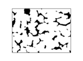
- FIG. 1 is a diagram showing an example of an image observed with a microscope of the microstructure of a heat-treated object cast using an austenitic casting material.
- FIG. 2 is a diagram showing an area occupied by graphite in the image shown in FIG.
- FIG. 3 is a diagram showing a region occupied by an intermetallic compound mainly composed of iron (Fe) in the image shown in FIG.
- FIG. 4 is a diagram showing a region occupied by the austenite phase in the image shown in FIG.
- the iron casting according to the embodiment of the present invention can be manufactured by subjecting a heat-treated object cast using an austenitic casting material to a predetermined heat treatment described below.
- austenitic casting material means a material in which the main structure of the parent phase (iron base structure excluding graphite) of a cast heat-treated object at room temperature is an austenite phase.
- the proportion of austenite phase in the matrix of the heat-treated object is 50% or more.
- the proportion of the austenite phase in the matrix of the heat-treated object is preferably 70% or more, more preferably 80% or more, more preferably 85% or more, and preferably 90% or more. More preferably, it is 95% or more.
- FIG. 1 is a diagram showing an example of an image observed with a microscope of the microstructure of a heat-treated object cast using an austenitic casting material.
- FIG. 2 is a diagram showing an area occupied by graphite in the image shown in FIG.
- FIG. 3 is a diagram showing a region occupied by an intermetallic compound mainly composed of iron (Fe) in the image shown in FIG.
- FIG. 4 is a diagram showing a region occupied by the austenite phase in the image shown in FIG.
- the "area of the matrix of the heat-treated object" can be calculated by subtracting the "area of the region occupied by graphite" shown in Figure 2 from the "area of the entire microstructure of the heat-treated object” shown in Figure 1. I can do it.
- the "area of the austenite phase” is determined by subtracting the "area of the region occupied by the intermetallic compound mainly composed of iron (Fe)" shown in Figure 3 from the "area of the matrix of the heat-treated object” calculated above. It can be calculated. Therefore, the "proportion of the austenite phase in the matrix of the heat-treated object” is calculated by dividing the "area of the austenite phase (see Figure 4)" calculated above by the "area of the matrix of the heat-treated object”. can do.
- general-purpose image processing software is used to calculate the number of pixels in the area corresponding to each area shown in Figures 1 to 4.
- the proportion of austenite phase is 84.6% (approximately 85%).
- the proportion of the austenite phase in the matrix of the heat-treated object is 100%.
- casting includes casting by various casting methods such as sand casting, metal mold casting, die casting, and lost wax casting.
- mass % of an element means the percentage of the mass of the element with respect to the mass of the austenitic casting material.
- the expression “element of X% by mass or more and Y% by mass or less” means that the mass% of the element is X% or more and Y% or less.
- the notation “0 mass % Y mass % or less of an element” means that the element is not included or that the mass % of the element is Y % or less.
- the "remainder” means components other than the listed elements among the components constituting the austenitic casting material.
- the first form of the austenitic casting material (hereinafter referred to as “this material”) contains Ni in an amount of 26.0% by mass to 50.0% by mass, and the balance is Fe and unavoidable elements.
- the first form of the present material may be referred to as “the first form of the present material (Ni--Fe composition)”.
- the first form of the present material contains Ni in an amount of 26.0% by mass or more and 50.0% by mass or less.
- Ni is segregated around graphite by setting the Ni content to 26.0% by mass or more and 50.0% by mass or less. That is, austenite is stabilized by concentrating Ni in the region around graphite.
- austenite By setting the lower limit of the Ni content to 26.0% by mass, austenite can be stabilized and martensite generation can be suppressed. Therefore, it is possible to suppress a decrease in the ductility of iron castings and to improve the machinability of iron castings.
- the upper limit of the Ni content to 50.0% by mass, it is possible to suppress an increase in the coefficient of linear expansion. The same applies to the following forms of the present material.
- the remainder in the first form of the material is Fe and unavoidable elements.
- unavoidable elements contained in the remainder include P (phosphorus), S (sulfur), Cu (copper), Al (aluminum), Cr (chromium), Mo (molybdenum), V (vanadium), and Ti (titanium). , Zn (zinc), and other elements.
- the content of unavoidable elements is preferably 10.0% by mass or less in total, more preferably 5.0% by mass or less in total, and 3.0% by mass or less in total. More preferably, the total amount is 1.0% by mass or less. The same applies to the following forms of the present material.
- the lower limit of the Ni content is preferably 26.5% by mass, more preferably 27.0% by mass, and even more preferably 27.5% by mass.
- it is 28.0% by mass, more preferably 28.5% by mass, more preferably 29.0% by mass, more preferably 29.5% by mass, More preferably 30.0% by mass, more preferably 30.5% by mass, more preferably 31.0% by mass, more preferably 31.5% by mass, 32. More preferably, it is 0% by mass.
- the upper limit of the Ni content is preferably 45.0% by mass, more preferably 42.0% by mass, more preferably 41.0% by mass, and 40.0% by mass.
- the content is more preferably 37.5% by mass, and even more preferably 37.0% by mass. The same applies to the following forms of the present material.
- the second form of this material contains Ni of 26.0% by mass or more and 50.0% by mass or less, C of 0.1% by mass or more and 3.5% by mass or less, and the balance is Fe and unavoidable elements.
- the second form of the present material may be referred to as "the second form of the present material (Ni--C--Fe composition)."
- the second form of the present material contains 0.1% by mass or more and 3.5% by mass or less of C.
- the liquidus temperature of the present material can be lowered. Therefore, the flowability of this material can be improved.
- the lower limit of the C content to 0.1% by mass
- the amount of crystallization or precipitation of graphite can be increased. Therefore, the machinability of iron castings can be improved.
- the upper limit of the C content to 3.5% by mass, graphite floating (carbon flotation) can be suppressed. Therefore, a decrease in strength and ductility of iron castings can be suppressed.
- the lower limit of the C content is preferably 0.15% by mass, more preferably 0.2% by mass, and even more preferably 0.4% by mass. Preferably, it is 0.7% by mass, more preferably 1.0% by mass, more preferably 1.25% by mass, more preferably 1.5% by mass, More preferably, it is 1.75% by mass.
- the upper limit of the content of C is preferably 3.3% by mass, more preferably 3.1% by mass, more preferably 3.0% by mass, and 2.95% by mass. It is more preferably 2.9% by mass, more preferably 2.85% by mass, more preferably 2.8% by mass, and more preferably 2.75% by mass. More preferably, it is 2.7% by mass, more preferably 2.65% by mass, more preferably 2.6% by mass, and more preferably 2.55% by mass. The content is more preferably 2.5% by mass. The same applies to the following forms of the present material.
- the third form of this material contains Ni of 26.0% by mass or more and 50.0% by mass or less, C of 0.1% by mass or more and 3.5% by mass or less, and 0.1% by mass or more and 3.5% by mass. It contains less than % by mass of Si, and the remainder is Fe and unavoidable elements.
- the third form of the present material may be referred to as "the third form of the present material (Ni-C-Si-Fe composition)".
- the third form of the present material contains 0.1% by mass or more and 3.5% by mass or less of Si.
- the Ni content is 26.0% by mass or more and 50.0% by mass or less
- the Si content is 0.1% by mass or more and 3.5% by mass or less.
- the lower limit of the Si content is preferably 0.25% by mass, more preferably 0.5% by mass, and even more preferably 0.75% by mass. It is preferably 1.0% by mass, more preferably 1.2% by mass, even more preferably 1.3% by mass, and even more preferably 1.4% by mass.
- the upper limit of the Si content is preferably 3.3% by mass, more preferably 3.1% by mass, more preferably 2.9% by mass, and more preferably 2.7% by mass. It is more preferably 2.5% by mass, more preferably 2.3% by mass, and even more preferably 2.1% by mass. The same applies to the following forms of the present material.
- the fourth form of this material includes 26.0% by mass or more and 50.0% by mass of Ni, 0.1% by mass or more and 3.5% by mass of C, and 0.1% by mass or more and 3.5% by mass. It contains Si of 0.1% by mass or more and 8.0% by mass or less of Co, and the balance is Fe and unavoidable elements.
- the fourth form of the present material may be referred to as "the fourth form of the present material (Ni-C-Si-Co-Fe composition)".
- the fourth form of the present material contains 0.1% by mass or more and 8.0% by mass or less of Co.
- the linear expansion coefficient can be further reduced due to the synergistic effect with Ni.
- the lower limit of the Co content By setting the lower limit of the Co content to 0.1% by mass, the minimum value of the coefficient of linear expansion can be reduced due to the synergistic effect with Ni.
- the upper limit of the Co content By setting the upper limit of the Co content to 8.0% by mass, it is possible to suppress the linear expansion coefficient from increasing after reaching a minimum value due to excessive addition of Co. The same applies to the following forms of the present material.
- the lower limit of the Co content is preferably 0.5% by mass, more preferably 1.0% by mass, and even more preferably 1.5% by mass.
- it is 2.0% by mass, more preferably 2.5% by mass, more preferably 3.0% by mass, more preferably 3.5% by mass, More preferably, it is 4.0% by mass.
- the upper limit of the Co content is preferably 7.5% by mass, more preferably 7.0% by mass, more preferably 6.5% by mass, and 6.25% by mass. More preferably, it is 6.0% by mass.
- the Ni content is 31.0% by mass or more and 34.0% by mass or less
- the Co content is 4.0% by mass or more and 5.5% by mass or less.
- the Co content is preferably 5.0% by mass or more and 8.0% by mass or less.
- the fifth form of this material includes 26.0% by mass or more and 50.0% by mass of Ni, 0.1% by mass or more and 3.5% by mass of C, and 0.1% by mass or more and 3.5% by mass. It contains Si of 0.1% by mass or more and 8.0% by mass or less of Co, and Mn of 0.01% by mass or more and 3.0% by mass or less, and the balance is Fe and unavoidable elements.
- the fifth form of the present material may be referred to as "the fifth form of the present material (Ni-C-Si-Co-Mn-Fe composition)."
- the fifth form of the present material contains Mn in an amount of 0.01% by mass or more and 3.0% by mass or less.
- Mn manganese
- the fifth form of this material contains Mn in an amount of 0.01% by mass or more and 3.0% by mass or less.
- the synergistic effect with Ni stabilizes austenite and suppresses the formation of martensite. can do. Therefore, the machinability of iron castings can be improved.
- austenite can be stabilized even at room temperature.
- the upper limit of the Mn content to 3.0% by mass, the amount of Mn dissolved in Fe (iron base) can be reduced. Therefore, it is possible to suppress an increase in the coefficient of linear expansion.
- the lower limit of the Mn content is preferably 0.05% by mass, more preferably 0.07% by mass, and even more preferably 0.08% by mass. It is preferably 0.09% by mass, more preferably 0.1% by mass.
- the upper limit of the Mn content is preferably 2.5% by mass, more preferably 2.0% by mass, more preferably 1.5% by mass, and 1.0% by mass. It is more preferable that it is, it is more preferable that it is 0.85 mass %, and it is still more preferable that it is 0.7 mass %. The same applies to the following forms of the present material.
- the sixth form of this material contains Ni of 26.0% by mass or more and 50.0% by mass or less, C of 0.1% by mass or more and 3.5% by mass or less, and 0.1% by mass or more and 3.5% by mass. It contains Si of 0.1% by mass or more and 8.0% by mass or less of Co, and Mg of 0.01% by mass or more and 0.2% by mass or less, and the balance is Fe and unavoidable elements.
- the sixth form of the present material may be referred to as "the sixth form of the present material (Ni-C-Si-Co-Mg-Fe composition)."
- the sixth form of the present material contains 0.01% by mass or more and 0.2% by mass or less of Mg.
- the spheroidizing effect of graphite is enhanced and Mg is segregated in the final solidified part. I can do it.
- the lower limit of the Mg content By setting the lower limit of the Mg content to 0.01% by mass, the spheroidizing effect of graphite can be enhanced.
- the upper limit of the Mg content to 0.2% by mass, it is possible to suppress the generation of Mg oxides or sulfides. Therefore, it is possible to suppress a decrease in the flowability of the present material. Furthermore, casting defects in iron castings can be reduced.
- the lower limit of the Mg content is preferably 0.02% by mass, more preferably 0.03% by mass, and even more preferably 0.04% by mass. preferable.
- the upper limit of the Mg content is preferably 0.15% by mass, more preferably 0.1% by mass, and even more preferably 0.08% by mass. The same applies to the following forms of the present material.
- the seventh form of this material contains Ni of 26.0% by mass or more and 50.0% by mass or less, C of 0.1% by mass or more and 3.5% by mass or less, and 0.1% by mass or more and 3.5% by mass. Si of not more than 0.1% by mass and not more than 8.0% by mass, Co of not less than 0.01% by mass and not more than 3.0% by mass, and not less than 0.01% by mass and not more than 0.2% by mass.
- Mg is included, and the remainder is Fe and inevitable elements.
- the seventh form of the present material may be referred to as "the seventh form of the present material (Ni-C-Si-Co-Mn-Mg-Fe composition)."
- the eighth form of this material contains Ni of 26.0% by mass or more and 50.0% by mass or less, C of 0.1% by mass or more and 3.5% by mass or less, and 0.1% by mass or more and 3.5% by mass. It contains Si of 0.01% by mass or more and 3.0% by mass or less of Mn, and the balance is Fe and unavoidable elements.
- the eighth form of the present material may be referred to as "the eighth form of the present material (Ni-C-Si-Mn-Fe composition)".
- the ninth form of this material includes Ni of 26.0% by mass or more and 50.0% by mass or less, C of 0.1% by mass or more and 3.5% by mass or less, and 0.1% by mass or more and 3.5% by mass or less. It contains Si of 0.01% by mass or more and 3.0% by mass or less of Mn, and Mg of 0.01% by mass or more and 0.2% by mass or less, and the balance is Fe and unavoidable elements.
- the ninth form of the present material may be referred to as "the ninth form of the present material (Ni-C-Si-Mn-Mg-Fe composition)".
- the tenth form of this material includes 26.0% by mass or more and 50.0% by mass of Ni, 0.1% by mass or more and 3.5% by mass of C, and 0.1% by mass or more and 3.5% by mass. It contains Si of 0.01% by mass or more and 0.2% by mass or less of Mg, and the balance is Fe and unavoidable elements.
- the tenth form of the present material may be referred to as "the tenth form of the present material (Ni-C-Si-Mg-Fe composition)."
- the first form of heat treatment performed on a heat-treated object cast using this material (hereinafter referred to as "main heat treatment") is to hold the heat-treated object at a first holding temperature of 850°C or higher and 1250°C or lower.
- the method includes a first holding step and, after the first holding step, a first cooling step of cooling the heat-treated object to a first cooling end temperature of ⁇ 150° C. or more and 150° C. or less.
- the first holding step includes holding the heat treatment object for a first holding time of 0.25 hours or more and 100 hours or less. Note that the first form of the heat treatment may include other heat treatment steps before and after each of the first holding step and the first cooling step.
- the heat treatment object cast using this material is sequentially subjected to the first holding step and the first holding step.
- the coefficient of linear expansion of iron castings can be reduced more reliably.
- the heat treatment target in the first holding step, is held at a first holding temperature (850°C or more and 1250°C or less) and a first holding time (0.25 hours or more and 100 hours or less). hold it. Then, in a first cooling step after the first holding step, the heat treatment target is cooled to a first cooling end temperature (-150° C. or higher and 150° C. or lower).
- the first cooling step includes cooling the heat treatment object at a first cooling rate of 0.01° C./min or more and 300° C./min or less.
- the first cooling rate is preferably 0.01°C/min or more and 20°C/min or less.
- the first holding time is preferably 2.5 hours or more and 25 hours or less.
- the first cooling end temperature is preferably 0°C or more and 100°C or less.
- the lower limit of the first holding temperature is preferably 875°C, more preferably 900°C, more preferably 925°C, and more preferably 950°C.
- the temperature is more preferably 975°C, more preferably 1000°C, and even more preferably 1025°C.
- the upper limit of the first holding temperature is preferably 1225°C, more preferably 1200°C, more preferably 1175°C, more preferably 1150°C, and more preferably 1125°C. It is even more preferable. The same applies to the following form of this heat treatment.
- the lower limit of the first holding time is preferably 0.5 hours, more preferably 1.0 hours, and more preferably 1.5 hours; More preferably 2.0 hours, more preferably 2.5 hours, more preferably 3.0 hours, more preferably 3.5 hours, and more preferably 4.0 hours. It is even more preferable.
- the upper limit of the first holding time is preferably 90 hours, more preferably 80 hours, more preferably 70 hours, more preferably 60 hours, and 50 hours. more preferably 40 hours, more preferably 30 hours, more preferably 25 hours, more preferably 20 hours, more preferably 15 hours, More preferably, the heating time is 10 hours. The same applies to the following form of this heat treatment.
- the lower limit of the first cooling end temperature is preferably -125°C, more preferably -100°C, more preferably -75°C, and more preferably -50°C.
- the temperature is more preferably -25°C, and even more preferably 0°C.
- the upper limit of the first cooling end temperature is preferably 125°C, more preferably 100°C, more preferably 75°C, and even more preferably 50°C. The same applies to the following form of this heat treatment.
- the lower limit of the first cooling rate is preferably 0.1°C/min, more preferably 0.2°C/min, and more preferably 0.3°C/min. More preferably, it is 0.4°C/min, more preferably 0.5°C/min, more preferably 0.6°C/min, and more preferably 0.7°C/min. More preferably, it is 0.75°C/min, and even more preferably 0.75°C/min.
- the upper limit of the first cooling rate is preferably 250°C/min, more preferably 200°C/min, more preferably 150°C/min, and more preferably 100°C/min. is more preferable, more preferably 50°C/min, more preferably 25°C/min, more preferably 10°C/min, even more preferably 5°C/min.
- the second form of heat treatment includes a first holding step in which the object to be heat treated is held at a first holding temperature of 850°C or more and 1250°C or less, and after the first holding step, the object to be heat treated is heated to -150°C. and a first cooling step of cooling to a first cooling end temperature of 150° C. or less.
- the first holding step includes holding the heat treatment object for a first holding time of 0.25 hours or more and 100 hours or less.
- the first cooling process includes a primary cooling process in which the heat treatment target is cooled at a primary cooling rate, and a secondary cooling process in which the heat treatment target is cooled at a secondary cooling rate higher than the primary cooling rate after the primary cooling process.
- the primary cooling step includes cooling the heat treatment object to a primary cooling end temperature of 250° C. or more and 950° C. or less.
- the secondary cooling step includes cooling the heat treatment object to a first cooling end temperature (-150° C. or higher and 150° C. or lower).
- the second form of the main heat treatment may include other heat treatment steps before and after each of the first holding step and the first cooling step.
- the heat treatment object cast using this material is sequentially subjected to the first holding step and the first holding step.
- the coefficient of linear expansion of iron castings can be reduced more reliably.
- the heat treatment target in the first holding step, is held at a first holding temperature (850°C or more and 1250°C or less) and a first holding time (0.25 hours or more and 100 hours or less). hold it. Then, in a first cooling step after the first holding step, the heat treatment target is cooled to a first cooling end temperature (-150° C. or higher and 150° C. or lower).
- a first holding step it is possible to reduce the solidification segregation of solute elements in the heat-treated object and to reduce the relative difference in crystal orientation (crystal orientation difference) inside each crystal grain constituting the austenite phase. can. This makes it possible to arrange the crystal lattice in the austenite phase. As a result, the coefficient of linear expansion of the iron casting can be reduced.
- the first cooling step after the first holding step is a primary cooling step in which the object to be heat treated is cooled at the primary cooling rate; and a secondary cooling step in which the object is cooled at a secondary cooling rate that is higher than the primary cooling rate.
- the heat treatment target is cooled at the primary cooling rate to the primary cooling end temperature (250° C. or higher and 950° C. or lower).
- This primary cooling step allows carbon in the austenite phase to diffuse toward the graphite side. Therefore, the amount of solid solute carbon in the austenite phase can be reduced. Therefore, excessive distortion of the crystal lattice in the austenite phase can be suppressed.
- the coefficient of linear expansion of the iron casting can be further reduced.
- the heat-treated object is cooled to a first cooling end temperature (-150° C. or higher and 150° C. or lower) at a secondary cooling rate that is higher than the primary cooling rate.
- This secondary cooling step tends to increase the amount of change in spontaneous volumetric magnetostriction due to temperature change below the Curie point. Therefore, in a temperature change below the Curie point, the volume change due to spontaneous bulk magnetostriction and the volume change due to crystal lattice vibration are likely to cancel each other out. Therefore, it is easy to suppress volume fluctuations due to temperature changes. As a result, it is easier to further reduce the coefficient of linear expansion of iron castings.
- the primary cooling rate is preferably 0.01°C/min or more and 20°C/min or less, and the secondary cooling rate is preferably 1°C/min or more and 40000°C/min or less. .
- the secondary cooling rate is preferably 100°C/min or more and 40000°C/min or less.
- the first holding time is preferably 2.5 hours or more and 25 hours or less.
- the primary cooling end temperature is preferably 450°C or more and 850°C or less.
- the first cooling end temperature is preferably 0°C or more and 100°C or less.
- the lower limit of the primary cooling end temperature is preferably 275°C, more preferably 300°C, more preferably 325°C, and most preferably 350°C.
- the temperature is 375°C, more preferably 400°C, more preferably 425°C, more preferably 450°C, more preferably 475°C, and more preferably 500°C.
- the temperature is more preferably 525°C, more preferably 550°C, more preferably 575°C, and even more preferably 600°C.
- the upper limit of the primary cooling end temperature is preferably 925°C, more preferably 900°C, more preferably 875°C, more preferably 850°C, and 825°C. is more preferable, and even more preferably 800°C.
- the lower limit of the primary cooling rate is preferably 0.1°C/min, more preferably 0.5°C/min, and more preferably 0.75°C/min. is more preferably 1.0°C/min, more preferably 1.25°C/min, more preferably 1.5°C/min, and more preferably 1.75°C/min. It is even more preferable that there be.
- the upper limit of the primary cooling rate is preferably 17.5°C/min, more preferably 15.0°C/min, more preferably 12.5°C/min, and 10.0°C/min. C/min is more preferable, and even more preferably 7.5 C/min.
- the lower limit of the secondary cooling rate is preferably 2.5°C/min, more preferably 5°C/min, and preferably 7.5°C/min. More preferably, 10°C/min, more preferably 50°C/min, more preferably 100°C/min, more preferably 200°C/min, and even more preferably 300°C/min. More preferably, it is 400°C/min, more preferably 500°C/min, and even more preferably 600°C/min.
- the upper limit of the secondary cooling rate is preferably 37,500°C/min, more preferably 35,000°C/min, more preferably 32,500°C/min, and preferably 30,000°C/min. More preferably, it is 27,500°C/min, and even more preferably 25,000°C/min.
- the third form of heat treatment includes a first holding step in which the object to be heat treated is held at a first holding temperature of 850°C to 1250°C, and after the first holding step, the object to be heat treated is heated to -150°C.
- a first cooling step in which the object is cooled to a first cooling end temperature of not less than 150°C
- a second cooling step in which the object to be heat treated is held at a second holding temperature of not less than 250°C and not more than 950°C after the first cooling step.
- a second cooling step of cooling the heat-treated object to a second cooling end temperature of ⁇ 150° C. or more and 150° C. or less.
- the first holding step includes holding the heat treatment object for a first holding time of 0.25 hours or more and 100 hours or less.
- the second holding step includes holding the heat-treated object for a second holding time of 0.25 hours or more and 25 hours or less.
- the third form of the heat treatment includes other heat treatment steps before and after each of the first holding step, first cooling step, second holding step, and second cooling step. Good too.
- the heat treatment object cast using the present material is sequentially subjected to the first holding step and the first holding step.
- the heat treatment target in the first holding step, is held at a first holding temperature (850°C or more and 1250°C or less) and a first holding time (0.25 hours or more and 100 hours or less). hold it. Then, in a first cooling step after the first holding step, the heat treatment target is cooled to a first cooling end temperature (-150° C. or higher and 150° C. or lower).
- a first holding step it is possible to reduce the solidification segregation of solute elements in the heat-treated object and to reduce the relative difference in crystal orientation (crystal orientation difference) inside each crystal grain constituting the austenite phase. can. This makes it possible to arrange the crystal lattice in the austenite phase. As a result, the coefficient of linear expansion of the iron casting can be reduced.
- the heat treatment target is held at a second holding temperature (250° C. or higher and 950° C. or lower) in a second holding step after the first cooling step. Then, in a second cooling step after the second holding step, the heat treatment target is cooled to a second cooling end temperature (-150° C. or higher and 150° C. or lower).
- This second cooling step tends to increase the amount of change in spontaneous volume magnetostriction due to temperature change below the Curie point. Therefore, in a temperature change below the Curie point, the volume change due to spontaneous bulk magnetostriction and the volume change due to crystal lattice vibration are likely to cancel each other out. Therefore, it is easy to suppress volume fluctuations due to temperature changes. As a result, it is easier to further reduce the coefficient of linear expansion of iron castings.
- the first cooling step preferably includes cooling the heat treatment object at a first cooling rate of 0.01° C./min or more and 300° C./min or less.
- the first cooling rate is preferably 1° C./min or more and 50° C./min or less.
- the second cooling step preferably includes cooling the heat-treated object at a second cooling rate of 1° C./min or more and 40000° C./min or less.
- the second cooling rate is preferably 100° C./min or more and 10000° C./min or less.
- the first holding time is preferably 2.5 hours or more and 25 hours or less.
- the first cooling end temperature is preferably 0°C or more and 100°C or less.
- the second holding temperature is preferably 550°C or more and 950°C or less.
- the second cooling end temperature is preferably 0°C or more and 50°C or less.
- the lower limit of the first cooling rate is preferably 1.0°C/min, more preferably 5.0°C/min, and more preferably 7.5°C/min. More preferably, the rate is 10.0°C/min, more preferably 12.0°C/min, and even more preferably 14.0°C/min.
- the upper limit of the first cooling rate is preferably 250°C/min, more preferably 200°C/min, more preferably 150°C/min, and more preferably 100°C/min. is more preferable, more preferably 75°C/min, more preferably 50°C/min, more preferably 45°C/min, and even more preferably 40°C/min.
- the lower limit of the second holding temperature is preferably 275°C, more preferably 300°C, more preferably 325°C, and preferably 350°C. more preferably 375°C, more preferably 400°C, more preferably 425°C, more preferably 450°C, more preferably 475°C, and more preferably 500°C.
- the temperature is more preferably 525°C, more preferably 550°C, more preferably 575°C, and even more preferably 600°C.
- the upper limit of the second holding temperature is preferably 925°C, more preferably 900°C, more preferably 875°C, more preferably 850°C, and more preferably 825°C. More preferably, the temperature is 800°C.
- the lower limit of the second holding time is preferably 0.3 hours, more preferably 0.4 hours, more preferably 0.5 hours, More preferably 0.6 hours, more preferably 0.7 hours, more preferably 0.8 hours, more preferably 0.9 hours, and 1.0 hours. It is even more preferable.
- the upper limit of the second holding time is preferably 20 hours, more preferably 15 hours, more preferably 10 hours, more preferably 9 hours, and more preferably 8 hours. is more preferable, more preferably 7 hours, more preferably 6 hours, and even more preferably 5 hours.
- the lower limit of the second cooling end temperature is preferably -125°C, more preferably -100°C, more preferably -75°C, and more preferably -50°C.
- the temperature is more preferably -25°C, and even more preferably 0°C.
- the upper limit of the second cooling end temperature is preferably 125°C, more preferably 100°C, more preferably 75°C, more preferably 50°C, and even more preferably 40°C.
- the temperature is more preferably 30°C, and even more preferably 30°C.
- the lower limit of the second cooling rate is preferably 25°C/min, more preferably 50°C/min, and more preferably 75°C/min.
- the rate is more preferably 100°C/min, more preferably 200°C/min, even more preferably 300°C/min, and even more preferably 400°C/min.
- the upper limit of the second cooling rate is preferably 35,000°C/min, more preferably 30,000°C/min, more preferably 25,000°C/min, and 20,000°C/min.
- the iron casting of the first embodiment is based on the fifth form (Ni-C-Si-Co-Mn-Fe composition) and the seventh form (Ni-C-Si-Co-Mn-Mg-Fe composition) of the present material.
- the eighth form Ni-C-Si-Mn-Fe composition
- the ninth form Ni-C-Si-Mn-Mg-Fe composition
- This is an iron casting obtained by performing the second form of this heat treatment.
- the linear expansion coefficient of the iron casting can be reduced as described above.
- the object to be heat treated is cast using an austenitic casting material with a Ni content of 26.0% by mass or more, the Ms point (from austenite to It is easy to lower the temperature at which transformation to martensite begins. Therefore, it is easy to provide iron castings in which martensite generation is suppressed.
- the solidification segregation of solute elements in the heat treatment object is reduced, and as a result, Ni distributed at a low concentration in the final solidified part of the heat treatment object can be highly concentrated. Thereby, the Ms point in the final solidification part can be further lowered.
- the generation of martensite is further suppressed. can do. Therefore, it is possible to provide an iron casting in which thermal expansion is reduced and martensite formation is suppressed. The same applies to the following embodiments.
- the iron casting of the second embodiment is based on the fifth form (Ni-C-Si-Co-Mn-Fe composition) and the seventh form (Ni-C-Si-Co-Mn-Mg-Fe composition) of the present material.
- This is an iron casting obtained by performing the third form of heat treatment on a heat-treated object cast using the composition) and the ninth form (Ni-C-Si-Mn-Mg-Fe composition).
- the linear expansion coefficient of the iron casting can be reduced as described above.
- the iron casting of the third embodiment is based on the fifth form (Ni-C-Si-Co-Mn-Fe composition) and the seventh form (Ni-C-Si-Co-Mn-Mg-Fe composition) of the present material.
- This is an iron casting obtained by performing the first form of heat treatment on a heat-treated object cast using the composition) and the ninth form (Ni-C-Si-Mn-Mg-Fe composition).
- the linear expansion coefficient of the iron casting can be reduced as described above.
- an iron casting with reduced thermal expansion can be provided. Therefore, the iron castings of the above embodiments are suitable for a wide variety of uses that require low thermal expansion (coefficient).
- uses of the iron castings of the above embodiments include component parts of semiconductor manufacturing equipment, electronic component manufacturing equipment, machine tools, and the like.
- application examples in operating environments of about 20°C to 50°C include spindle holders for dicers, calibration gauges (gauge blocks, etc.) in semiconductor manufacturing equipment, work stages in machine tools, and wires in wire electrical discharge machines. A holding member is mentioned.
- examples of applications in use environments of about 20° C. to 100° C. (or 150° C.) include dry vacuum pump parts and card holders for probers in semiconductor manufacturing equipment.
- Table 1 shows the compositions of Examples in the first embodiment and the compositions of Comparative Examples.
- Table 2 shows the compositions of Examples in the second embodiment and the compositions of Comparative Examples thereof.
- Table 3 shows the compositions of Examples in the third embodiment and the compositions of Comparative Examples.
- the C (carbon) content is the value measured by combustion-infrared absorption method using a material carbon/sulfur analyzer "EMIA-Expert" manufactured by Horiba, Ltd. be.
- the content (mass%) of Si (silicon), Ni (nickel), Mg (magnesium), and Co (cobalt) was determined using inductively coupled plasma using an emission spectrometer "SPS3520UV” manufactured by Hitachi High-Tech Science Co., Ltd. This is a value measured by emission spectrometry. Further, the contents (mass %) of other elements are values measured by emission spectrometry using an emission spectrometer "PDA-8000" manufactured by Shimadzu Corporation.
- Table 4 shows the heat treatment conditions and average linear expansion coefficients of the examples in the first embodiment, and the heat treatment conditions and average linear expansion coefficients of comparative examples with respect to these.
- Table 5 shows the heat treatment conditions and average linear expansion coefficients of the examples in the second embodiment, and the heat treatment conditions and average linear expansion coefficients of comparative examples with respect to these.
- Table 6 shows the heat treatment conditions and average linear expansion coefficients of the examples in the third embodiment, and the heat treatment conditions and average linear expansion coefficients of the comparative examples.
- the holding temperature (°C) indicates the temperature at which the heat treatment object is held in the heat treatment furnace (heat treatment apparatus).
- As the heat treatment furnace a muffle furnace "QUICK TEMPER" manufactured by TEC Co., Ltd. was used.
- the holding time indicates the time during which the heat treatment object is held in a state where the inside of the heat treatment furnace is kept at the holding temperature.
- the cooling method refers to a method for cooling the heat-treated object.Furnace cooling is a method in which the heat-treated object is gradually cooled inside the heat treatment furnace, and natural air cooling is a method for cooling the heat-treated object outside the heat treatment furnace. It is a method of cooling in air, and rapid cooling is a method of rapidly cooling the object to be heat treated by immersing it in water, oil, a coolant using dry ice, liquid nitrogen, or the like. Further, the cooling end temperature (° C.) indicates the temperature at which cooling of the heat treatment object by the cooling method ends.
- the cooling end temperature is the surface temperature of the heat treatment object measured in the heat treatment furnace by bringing the temperature measurement part of the thermocouple into contact with the heat treatment object in the heat treatment furnace.
- the cooling end temperature in the case of natural air cooling and rapid cooling is the surface temperature of the heat treatment object measured outside the heat treatment furnace by bringing the temperature measurement part of the thermocouple into contact with the heat treatment object outside the heat treatment furnace.
- the cooling rate (°C/min) or (°C/sec) indicates the amount of change in temperature with respect to the time from the start to the end of cooling of the heat-treated object.
- the average linear expansion coefficient ( ⁇ 10 -6 /°C) was obtained from an iron casting (Y type B sample material) after the specified heat treatment was applied to the heat treatment object cast by sand casting method.
- the linear expansion coefficient measurement test piece (diameter 6 mm, length 25 mm) is a value measured according to ASTM standard (ASTM E228-17) using a thermal dilatometer "DIL 402 Expedis Supreme” manufactured by NETZSCH Japan Co., Ltd.
- the average coefficient of linear expansion up to each temperature (50°C, 100°C, 150°C) in Tables 4 to 6 is shown based on °C.
- the average linear expansion coefficient at 20°C or more and 50°C or less is 3.51 ⁇ 10 -6 /°C or less (Comparative Example 1-1 is 3.63 ⁇ 10 -6 /°C), average linear expansion coefficient at 20°C to 100°C is 3.58 ⁇ 10 -6 /°C or less (Comparative Example 1-1 is 3.90 ⁇ 10 -6 /°C), 20°C
- the average linear expansion coefficient at 150°C or lower is 4.09 ⁇ 10 ⁇ 6 /°C or less (4.28 ⁇ 10 ⁇ 6 /°C in Comparative Example 1-1).
- the thermal expansion of the iron castings can be reduced by setting the primary cooling end temperature to 950° C. or lower (particularly 900° C. or lower).
- the average linear expansion coefficient at 20°C or more and 50°C or less is 3.51 ⁇ 10 -6 /°C or less (Comparative Example 1-2 is 4.98 ⁇ 10 -6 /°C), average linear expansion coefficient at 20°C to 100°C is 3.58 ⁇ 10 -6 /°C or less (4.87 ⁇ 10 -6 /°C for Comparative Example 1-2), 20°C
- the average linear expansion coefficient at 150°C or lower is 4.09 ⁇ 10 ⁇ 6 /°C or less (comparative example 1-2 is 4.87 ⁇ 10 ⁇ 6 /°C).
- the average linear expansion coefficient at 20°C or more and 50°C or less is 3.30 ⁇ 10 -6 /°C or less (Comparative Example 2-1 is 3.54 ⁇ 10 -6 /°C), average linear expansion coefficient at 20°C to 100°C is 3.55 ⁇ 10 -6 /°C or less (Comparative Example 2-1 is 3.78 ⁇ 10 -6 /°C), 20°C Above, the average linear expansion coefficient at 150°C or lower is 4.05 ⁇ 10 ⁇ 6 /°C or lower (comparative example 2-1 is 4.15 ⁇ 10 ⁇ 6 /°C). As described above, in Examples 2-1 to 2-26, by setting the second holding temperature to 950° C. or lower (particularly 900° C. or lower), the thermal expansion of the iron castings can be reduced.
- the average linear expansion coefficient at 20°C or higher and 50°C or lower is 3.30 ⁇ 10 -6 /°C or less (Comparative Example 2-2 is 5.57 ⁇ 10 -6 /°C), average linear expansion coefficient at 20°C to 100°C is 3.55 ⁇ 10 -6 /°C or less (Comparative Example 2-2 is 5.47 ⁇ 10 -6 /°C), 20°C
- the average linear expansion coefficient at 150°C or lower is 4.05 ⁇ 10 ⁇ 6 /°C or lower (5.40 ⁇ 10 ⁇ 6 /°C in Comparative Example 2-2).
- the average linear expansion coefficient at 20°C or higher and 50°C or lower is 3.80 ⁇ 10 -6 /°C or less (Comparative Example 3-1 is 4.53 ⁇ 10 -6 /°C), average linear expansion coefficient at 20°C to 100°C is 4.16 ⁇ 10 -6 /°C or less (comparative example 3-1 is 5.02 ⁇ 10 -6 /°C), 20°C
- the average linear expansion coefficient at 150°C or lower is 4.84 ⁇ 10 ⁇ 6 /°C or less (5.58 ⁇ 10 ⁇ 6 /°C in Comparative Example 3-1).
- the thermal expansion of the iron castings can be reduced.
- the average linear expansion coefficient at 20°C or more and 50°C or less is 3.80 ⁇ 10 -6 /°C or less (Comparative Example 3-2 is 3.89 ⁇ 10 -6 /°C), and the average linear expansion coefficient at temperatures above 20°C and below 100°C was 4.16 ⁇ 10 -6 /°C or less (comparative example 3-2 was 4.17 ⁇ 10 -6 /°C).
- the thermal expansion of the iron castings can be reduced.
- the average linear expansion coefficient at 20°C or more and 50°C or less is 3.80 ⁇ 10 -6 /°C or less (Comparative Example 3-3 is 5.87 ⁇ 10 -6 /°C), average linear expansion coefficient at 20°C to 100°C is 4.16 ⁇ 10 -6 /°C or less (Comparative Example 3-3 is 5.72 ⁇ 10 -6 /°C), 20°C Above, the average linear expansion coefficient at 150°C or lower is 4.84 ⁇ 10 ⁇ 6 /°C or less (comparative example 3-3 is 5.67 ⁇ 10 ⁇ 6 /°C). As described above, in Examples 3-1 to 3-13, by setting the first holding temperature to 1250° C. or lower (particularly 1200° C. or lower), the thermal expansion of the iron castings can be reduced.
- Example 3-9 Comparative Example 3-1 and Comparative Example 3-3
- the casting materials of Example 3-9, Comparative Example 3-1, and Comparative Example 3-3 do not contain Co.
- the first holding temperature in Example 3-9 is 850°C or more and 1250°C or less
- the first holding temperature in Comparative Example 3-1 is 800°C.
- the first holding temperature of Comparative Example 3-3 is 1300°C.
- Example 3-9 the average coefficient of linear expansion at temperatures above 20°C and below 150°C is reduced.
- the average linear expansion coefficient at 20°C or higher and 150°C or lower is 4.84 ⁇ 10 -6 /°C or less (Comparative Example 3-1 is 5.58 ⁇ 10 -6 /°C , Comparative Example 3-3 was 5.67 ⁇ 10 ⁇ 6 /°C).
- the thermal expansion of the iron casting at high temperatures can be reduced by not containing Co and by setting the first holding temperature to 850° C. or more and 1250° C. or less.
- Example 3-1 to 3-8 and Examples 3-10 to 3-13 are reduced compared to Comparative Example 3-2.
- the average linear expansion coefficient at 20°C or higher and 150°C or lower is 4.49 ⁇ 10 -6 / °C or less (comparative example 3-2 was 4.53 ⁇ 10 ⁇ 6 /°C).
- Co is contained and the first holding temperature is set to 850°C or more and 1250°C or less. This makes it possible to reduce the thermal expansion of iron castings at high temperatures.
- the present disclosure can also have the following configuration.
- An iron casting obtained by performing a first heat treatment on a heat treatment object cast using an austenitic casting material The iron casting, wherein performing the first heat treatment includes maintaining the heat treatment object at a first temperature range of 950°C or more and 1200°C or less.
- the iron casting according to (1), wherein holding in the first temperature range includes holding the heat treatment object for a time range of 1 hour or more and 100 hours or less.
- Further comprising performing a second heat treatment on the object to be heat treated after performing the first heat treatment The iron casting according to (1) or (2), wherein performing the second heat treatment includes cooling the object to be heat treated to a second temperature range of 300°C or higher and 900°C or lower.
- cooling to the second temperature range includes cooling the heat-treated object at a cooling rate range of 0.01° C./min to 20° C./min.
- a method for producing iron castings comprising performing a first heat treatment on a heat treatment object cast using an austenitic casting material, The manufacturing method, wherein performing the first heat treatment includes maintaining the heat treatment target at a first temperature range of 950°C or higher and 1200°C or lower.
- the manufacturing method according to (11), wherein holding the object in the first temperature range includes holding the object to be heat treated for a time range of 1 hour or more and 100 hours or less.
- Further comprising performing a second heat treatment on the heat treatment target after performing the first heat treatment The manufacturing method according to (11) or (12), wherein performing the second heat treatment includes cooling the object to be heat treated to a second temperature range of 300°C or higher and 900°C or lower.
- cooling to the second temperature range includes cooling the heat treatment target at a cooling rate range of 0.01° C./min to 20° C./min.
- cooling to the third temperature range includes cooling the heat treatment object to a third temperature range of 0° C. or higher and 100° C. or lower.
- cooling to the third temperature range includes cooling the heat treatment object at a cooling rate range of 1° C./second to 1000° C./second.
Landscapes
- Chemical & Material Sciences (AREA)
- Engineering & Computer Science (AREA)
- Mechanical Engineering (AREA)
- Materials Engineering (AREA)
- Metallurgy (AREA)
- Organic Chemistry (AREA)
- Physics & Mathematics (AREA)
- Thermal Sciences (AREA)
- Crystallography & Structural Chemistry (AREA)
- Heat Treatment Of Articles (AREA)
Priority Applications (4)
| Application Number | Priority Date | Filing Date | Title |
|---|---|---|---|
| DE112023001366.7T DE112023001366T5 (de) | 2022-03-14 | 2023-03-13 | Eisengussstück und verfahren zu dessen herstellung |
| CN202380027030.9A CN118922564A (zh) | 2022-03-14 | 2023-03-13 | 铁铸件和制造该铁铸件的方法 |
| US18/846,783 US20250188577A1 (en) | 2022-03-14 | 2023-03-13 | Iron casting and method of manufacturing it |
| JP2024508165A JP7737754B2 (ja) | 2022-03-14 | 2023-03-13 | 鉄鋳物およびそれを製造する方法 |
Applications Claiming Priority (2)
| Application Number | Priority Date | Filing Date | Title |
|---|---|---|---|
| JP2022-038788 | 2022-03-14 | ||
| JP2022038788 | 2022-03-14 |
Publications (1)
| Publication Number | Publication Date |
|---|---|
| WO2023176791A1 true WO2023176791A1 (ja) | 2023-09-21 |
Family
ID=88023791
Family Applications (1)
| Application Number | Title | Priority Date | Filing Date |
|---|---|---|---|
| PCT/JP2023/009691 Ceased WO2023176791A1 (ja) | 2022-03-14 | 2023-03-13 | 鉄鋳物およびそれを製造する方法 |
Country Status (5)
| Country | Link |
|---|---|
| US (1) | US20250188577A1 (https=) |
| JP (1) | JP7737754B2 (https=) |
| CN (1) | CN118922564A (https=) |
| DE (1) | DE112023001366T5 (https=) |
| WO (1) | WO2023176791A1 (https=) |
Citations (5)
| Publication number | Priority date | Publication date | Assignee | Title |
|---|---|---|---|---|
| JPS62284039A (ja) * | 1986-06-03 | 1987-12-09 | Nippon Chuzo Kk | 低熱膨張鋳鉄 |
| JPH04141545A (ja) * | 1990-10-01 | 1992-05-15 | Kurimoto Ltd | 高温低熱膨張鋳鉄 |
| JP2000119793A (ja) * | 1998-10-13 | 2000-04-25 | Toshiba Corp | 低温安定性低膨張鋳鉄およびその製造方法 |
| JP2003138336A (ja) * | 2001-10-31 | 2003-05-14 | Kogi Corp | 低熱膨張鋳鋼 |
| JP2019173110A (ja) * | 2018-03-29 | 2019-10-10 | 虹技株式会社 | 球状黒鉛鋳鉄とその製造方法 |
Family Cites Families (1)
| Publication number | Priority date | Publication date | Assignee | Title |
|---|---|---|---|---|
| JP2010095747A (ja) | 2008-10-15 | 2010-04-30 | Nabeya Co Ltd | 低熱膨張鋳鉄材の製造方法 |
-
2023
- 2023-03-13 DE DE112023001366.7T patent/DE112023001366T5/de active Pending
- 2023-03-13 US US18/846,783 patent/US20250188577A1/en active Pending
- 2023-03-13 CN CN202380027030.9A patent/CN118922564A/zh active Pending
- 2023-03-13 JP JP2024508165A patent/JP7737754B2/ja active Active
- 2023-03-13 WO PCT/JP2023/009691 patent/WO2023176791A1/ja not_active Ceased
Patent Citations (5)
| Publication number | Priority date | Publication date | Assignee | Title |
|---|---|---|---|---|
| JPS62284039A (ja) * | 1986-06-03 | 1987-12-09 | Nippon Chuzo Kk | 低熱膨張鋳鉄 |
| JPH04141545A (ja) * | 1990-10-01 | 1992-05-15 | Kurimoto Ltd | 高温低熱膨張鋳鉄 |
| JP2000119793A (ja) * | 1998-10-13 | 2000-04-25 | Toshiba Corp | 低温安定性低膨張鋳鉄およびその製造方法 |
| JP2003138336A (ja) * | 2001-10-31 | 2003-05-14 | Kogi Corp | 低熱膨張鋳鋼 |
| JP2019173110A (ja) * | 2018-03-29 | 2019-10-10 | 虹技株式会社 | 球状黒鉛鋳鉄とその製造方法 |
Also Published As
| Publication number | Publication date |
|---|---|
| US20250188577A1 (en) | 2025-06-12 |
| CN118922564A (zh) | 2024-11-08 |
| JP7737754B2 (ja) | 2025-09-11 |
| DE112023001366T5 (de) | 2025-01-09 |
| JPWO2023176791A1 (https=) | 2023-09-21 |
Similar Documents
| Publication | Publication Date | Title |
|---|---|---|
| JP6160942B1 (ja) | 低熱膨張超耐熱合金及びその製造方法 | |
| JP6046591B2 (ja) | オーステナイト系耐熱鋳鋼 | |
| JP6704276B2 (ja) | 鋳造用アルミニウム合金を用いた鋳造材の製造方法 | |
| JP6656013B2 (ja) | 低熱膨張鋳鋼品及びその製造方法 | |
| JP2019065344A (ja) | 低熱膨張合金 | |
| KR101571665B1 (ko) | 다이캐스팅용 알루미늄 합금 조성물 및 이를 이용하여 제조한 알루미늄 합금의 열처리 방법 | |
| JP6846806B2 (ja) | 低熱膨張合金 | |
| US11697864B2 (en) | Copper alloy strip having high heat resistance and thermal dissipation properties | |
| US20050236074A1 (en) | Copper alloy | |
| JP4768919B2 (ja) | 高強度低熱膨張鋳物鋼及び高強度低熱膨張鋳物鋼からなるガスタービンの翼環用及びシールリング保持環用リング形状部品 | |
| JP7610244B2 (ja) | 低熱膨張合金 | |
| JP7737754B2 (ja) | 鉄鋳物およびそれを製造する方法 | |
| JP2010095747A (ja) | 低熱膨張鋳鉄材の製造方法 | |
| JP4469269B2 (ja) | 高周波磁気特性の優れた電磁鋼板とその製造方法 | |
| JP7533128B2 (ja) | 過共晶Al-Si合金鋳物及びその製造方法 | |
| JP4687983B2 (ja) | Mn−Cu系制振合金の製造方法 | |
| JPH039179B2 (https=) | ||
| JP4737614B2 (ja) | Fe−Ni系合金板及びFe−Ni系合金板の製造方法 | |
| JP6802689B2 (ja) | 析出硬化型銅合金及びその製造方法 | |
| JP7666489B2 (ja) | 鋳造用アルミニウム合金、アルミニウム合金部材、及びアルミニウム合金部材の製造方法 | |
| JP6179325B2 (ja) | 連続鋳造用モールド材 | |
| JPH08269613A (ja) | 低熱膨張鋳鉄およびその製造方法 | |
| JPH06256890A (ja) | 耐熱性鋳物用鉄合金 | |
| ES2930080T3 (es) | Tamaño de grano uniforme en aleación de cobre espinodal trabajada en caliente | |
| JP6692466B2 (ja) | 低熱膨張合金 |
Legal Events
| Date | Code | Title | Description |
|---|---|---|---|
| 121 | Ep: the epo has been informed by wipo that ep was designated in this application |
Ref document number: 23770746 Country of ref document: EP Kind code of ref document: A1 |
|
| ENP | Entry into the national phase |
Ref document number: 2024508165 Country of ref document: JP Kind code of ref document: A |
|
| WWE | Wipo information: entry into national phase |
Ref document number: 202380027030.9 Country of ref document: CN |
|
| WWE | Wipo information: entry into national phase |
Ref document number: 2401005968 Country of ref document: TH |
|
| WWE | Wipo information: entry into national phase |
Ref document number: 18846783 Country of ref document: US |
|
| WWE | Wipo information: entry into national phase |
Ref document number: 112023001366 Country of ref document: DE |
|
| 122 | Ep: pct application non-entry in european phase |
Ref document number: 23770746 Country of ref document: EP Kind code of ref document: A1 |
|
| WWP | Wipo information: published in national office |
Ref document number: 18846783 Country of ref document: US |