WO2023176502A1 - 緩衝器および緩み止め構造 - Google Patents
緩衝器および緩み止め構造 Download PDFInfo
- Publication number
- WO2023176502A1 WO2023176502A1 PCT/JP2023/008015 JP2023008015W WO2023176502A1 WO 2023176502 A1 WO2023176502 A1 WO 2023176502A1 JP 2023008015 W JP2023008015 W JP 2023008015W WO 2023176502 A1 WO2023176502 A1 WO 2023176502A1
- Authority
- WO
- WIPO (PCT)
- Prior art keywords
- nut
- rod
- threaded portion
- male threaded
- axial direction
- Prior art date
- Legal status (The legal status is an assumption and is not a legal conclusion. Google has not performed a legal analysis and makes no representation as to the accuracy of the status listed.)
- Ceased
Links
Images






Classifications
-
- F—MECHANICAL ENGINEERING; LIGHTING; HEATING; WEAPONS; BLASTING
- F16—ENGINEERING ELEMENTS AND UNITS; GENERAL MEASURES FOR PRODUCING AND MAINTAINING EFFECTIVE FUNCTIONING OF MACHINES OR INSTALLATIONS; THERMAL INSULATION IN GENERAL
- F16B—DEVICES FOR FASTENING OR SECURING CONSTRUCTIONAL ELEMENTS OR MACHINE PARTS TOGETHER, e.g. NAILS, BOLTS, CIRCLIPS, CLAMPS, CLIPS OR WEDGES; JOINTS OR JOINTING
- F16B39/00—Locking of screws, bolts or nuts
- F16B39/02—Locking of screws, bolts or nuts in which the locking takes place after screwing down
- F16B39/12—Locking of screws, bolts or nuts in which the locking takes place after screwing down by means of locknuts
-
- F—MECHANICAL ENGINEERING; LIGHTING; HEATING; WEAPONS; BLASTING
- F16—ENGINEERING ELEMENTS AND UNITS; GENERAL MEASURES FOR PRODUCING AND MAINTAINING EFFECTIVE FUNCTIONING OF MACHINES OR INSTALLATIONS; THERMAL INSULATION IN GENERAL
- F16F—SPRINGS; SHOCK-ABSORBERS; MEANS FOR DAMPING VIBRATION
- F16F9/00—Springs, vibration-dampers, shock-absorbers, or similarly-constructed movement-dampers using a fluid or the equivalent as damping medium
- F16F9/10—Springs, vibration-dampers, shock-absorbers, or similarly-constructed movement-dampers using a fluid or the equivalent as damping medium using liquid only; using a fluid of which the nature is immaterial
- F16F9/14—Devices with one or more members, e.g. pistons, vanes, moving to and fro in chambers and using throttling effect
- F16F9/16—Devices with one or more members, e.g. pistons, vanes, moving to and fro in chambers and using throttling effect involving only straight-line movement of the effective parts
- F16F9/18—Devices with one or more members, e.g. pistons, vanes, moving to and fro in chambers and using throttling effect involving only straight-line movement of the effective parts with a closed cylinder and a piston separating two or more working spaces therein
-
- F—MECHANICAL ENGINEERING; LIGHTING; HEATING; WEAPONS; BLASTING
- F16—ENGINEERING ELEMENTS AND UNITS; GENERAL MEASURES FOR PRODUCING AND MAINTAINING EFFECTIVE FUNCTIONING OF MACHINES OR INSTALLATIONS; THERMAL INSULATION IN GENERAL
- F16F—SPRINGS; SHOCK-ABSORBERS; MEANS FOR DAMPING VIBRATION
- F16F9/00—Springs, vibration-dampers, shock-absorbers, or similarly-constructed movement-dampers using a fluid or the equivalent as damping medium
- F16F9/32—Details
Definitions
- the present invention relates to a shock absorber and a locking structure.
- This application claims priority based on Japanese Patent Application No. 2022-041128 filed in Japan on March 16, 2022, the contents of which are incorporated herein.
- a nut loosening device includes a first nut having a small diameter portion having a tapered surface whose diameter becomes thinner toward the tip side, and a second nut having a tapered fitting surface that fits into the small diameter portion. (For example, see Patent Document 1).
- the present invention aims to provide a shock absorber and a loosening prevention structure that can suppress the occurrence of loosening.
- a first aspect of the present invention includes a case member in which a working fluid is sealed, a flange portion, a rod-shaped portion protruding from an axial end surface of the flange portion and disposed within the case member, and a rod-shaped portion provided on the rod-shaped portion.
- a second nut is disposed so as to be sandwiched between the flange portion, and is threadedly engaged with the male threaded portion, and a first nut having a first inclined part inclined
- a second aspect of the present invention includes a cylinder in which a working fluid is sealed, a piston that is slidably fitted into the cylinder and partitions the inside of the cylinder into two chambers, and at least one chamber inside the cylinder.
- a rod-shaped member having a flange portion, a rod-shaped portion protruding from an axial end surface of the flange portion, and a male threaded portion provided in the rod-shaped portion; a fixing member into which the rod-shaped portion of the rod-shaped member is inserted;
- the rod-shaped portion of the rod-shaped member is inserted into the disk valve, and the fixing member and the disk valve are arranged so as to be sandwiched between the flange portion, and are threadedly engaged with the male threaded portion.
- the nut includes a first nut provided with a male threaded portion, and a second nut having an inclined portion whose inner diameter increases toward the first nut, and the inclined portion is threadedly engaged with the first male threade
- a third aspect of the present invention includes a rod-shaped member having a flange portion, a rod-shaped portion protruding from an axial end surface of the flange portion, and a male threaded portion provided in the rod-shaped portion, and the rod-shaped portion of the rod-shaped member is inserted.
- a fixing member arranged so as to sandwich the fixing member with the flange portion, screwed into the male threaded portion, and having an end inclined at an end opposite to the fixing member so as to be spaced apart from the male threaded portion; a first nut having an inclined portion; and a female threaded portion that is disposed between the first nut and the fixing member, and that is threadedly engaged with the male threaded portion between the first nut and the male threaded portion. and a second nut having a second inclined portion formed on the radial outer periphery of the female thread portion, the second inclined portion being at least partially in contact with the first inclined portion.
- FIG. 1 is a side sectional view showing a shock absorber according to a first embodiment of the present invention.
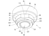
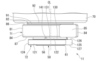
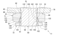
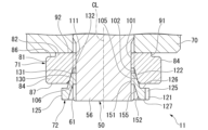
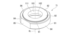
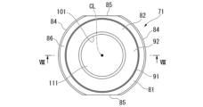
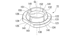
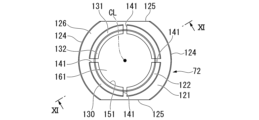
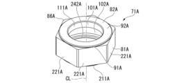
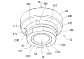
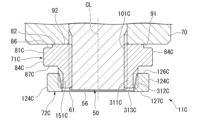
- FIG. 2 is a perspective view of main parts of the shock absorber. It is a side view of the main part which shows the same buffer. It is a side sectional view of the main part showing the same shock absorber. It is a side sectional view of the main part showing the same shock absorber. It is a perspective view which shows the 1st nut of the same shock absorber. It is a top view which shows the 1st nut of the same shock absorber.
- FIG. 8 is a sectional view taken along line VIII-VIII in FIG. 7 showing the first nut of the shock absorber. It is a perspective view which shows the 2nd nut of the same shock absorber.
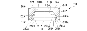
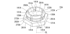
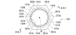
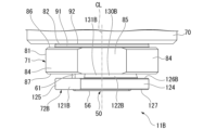
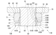
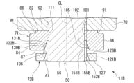
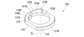
- FIG. 7 is a perspective view of essential parts of a shock absorber according to a second embodiment of the present invention. It is a side view of the main part which shows the same buffer. It is a side sectional view of the main part showing the same shock absorber. It is a side sectional view of the main part showing the same shock absorber. It is a perspective view which shows the 1st nut of the same shock absorber. It is a top view which shows the 1st nut of the shock absorber of 2nd Embodiment based on this invention.
- FIG. 7 is a perspective view of essential parts of a shock absorber according to a second embodiment of the present invention. It is a side view of the main part which shows the same buffer. It is a side sectional view of the main part showing the same shock absorber. It is a side sectional view of the main part showing the same shock absorber. It is a perspective view which shows the 1st nut of the same shock absorber. It is a top view which shows the 1st nut
- FIG. 18 is a sectional view taken along line XVIII-XVIII in FIG. 17 showing the first nut of the shock absorber. It is a perspective view which shows the 2nd nut of the same shock absorber. It is a top view which shows the 2nd nut of the same shock absorber.
- FIG. 21 is a sectional view taken along line XXI-XXI in FIG. 20 showing the second nut of the shock absorber.
- FIG. 7 is a perspective view of main parts of a shock absorber according to a third embodiment of the present invention. It is a side view of the main part which shows the same buffer. It is a side sectional view of the main part showing the same shock absorber. It is a side sectional view of the main part showing the same shock absorber.
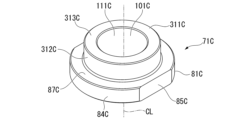
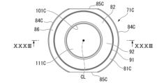
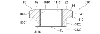
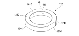
- FIG. 7 is a perspective view of essential parts of a shock absorber according to a fourth embodiment of the present invention. It is a side sectional view of the main part showing the same shock absorber. It is a perspective view which shows the 1st nut of the same shock absorber. It is a top view which shows the 1st nut of the same shock absorber.
- FIG. 33 is a sectional view taken along XXXIII-XXXIII in FIG.
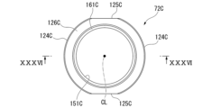
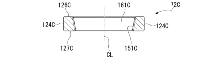
- FIG. 32 showing the first nut of the same shock absorber. It is a perspective view which shows the 2nd nut of the same shock absorber. It is a top view which shows the 2nd nut of the same shock absorber.
- FIG. 36 is a sectional view taken along XXXVI-XXXVI in FIG. 35 showing the second nut of the same shock absorber.
- FIG. 1 shows a buffer 11 according to a first embodiment.
- a shock absorber 11 shown in FIG. 1 is a shock absorber used in a suspension device of a vehicle such as an automobile or a railway vehicle.
- the shock absorber 11 is specifically a shock absorber used in a suspension device of an automobile.
- the shock absorber 11 includes a cylinder 14 that is a case member in which a working fluid is sealed.
- the cylinder 14 has an inner cylinder 15 and an outer cylinder 16.
- the inner cylinder 15 has a cylindrical shape.
- the outer cylinder 16 has a cylindrical shape with a bottom.
- the outer cylinder 16 is provided on the outer peripheral side of the inner cylinder 15 so as to cover the outer peripheral part of the inner cylinder 15.
- a reservoir chamber 18 is provided between the outer cylinder 16 and the inner cylinder 15.
- the outer cylinder 16 has a body part 21, a bottom part 22, and an opening 23.
- the body 21 has a cylindrical shape.
- the bottom portion 22 closes one end of the body portion 21 in the axial direction.
- the opening 23 is provided on the opposite side of the body 21 from the bottom 22.
- the shock absorber 11 has a valve body 25 and a rod guide 26.
- the valve body 25 has an annular shape and is fitted into one end of the inner cylinder 15 in the axial direction.
- the valve body 25 is placed on the bottom 22 of the outer cylinder 16.
- the valve body 25 constitutes a base valve 30.
- the base valve 30 is disposed within the outer tube 16 of the cylinder 14 and rests on the bottom portion 22.
- the rod guide 26 has an annular shape and is fitted into the other ends of the inner tube 15 and the outer tube 16 in the axial direction on the opposite side from the bottom portion 22 .
- One axial end of the inner cylinder 15 fits into the valve body 25 .
- the inner cylinder 15 is placed on the bottom 22 of the outer cylinder 16 via the valve body 25. Further, the other end of the inner cylinder 15 in the axial direction is fitted into the rod guide 26 .
- the inner cylinder 15 engages with the body 21 of the outer cylinder 16 via a rod guide 26. In this state, the inner cylinder 15 is positioned in the radial direction with respect to the outer cylinder 16.
- a passage groove 35 is formed in the valve body 25.
- the valve body 25 and the bottom 22 communicate with the inner cylinder 15 and the outer cylinder 16 via a passage groove 35.
- the space between the valve body 25 and the bottom portion 22 constitutes a reservoir chamber 18, similar to the space between the inner cylinder 15 and the outer cylinder 16.
- the shock absorber 11 has a seal member 41.
- the seal member 41 has an annular shape and is provided closer to the opening 23 of the outer cylinder 16 than the rod guide 26 is.
- the seal member 41 is also fitted into the inner circumferential portion of the body portion 21 similarly to the rod guide 26 .
- a locking portion 43 is formed at the end of the body portion 21 on the opening 23 side.
- the locking portion 43 is formed by plastically deforming the body portion 21 inward in the radial direction by crimping such as curling.
- the seal member 41 is held between the locking portion 43 and the rod guide 26.
- the seal member 41 closely contacts the body 21 of the outer cylinder 16 and closes the opening 23.
- the seal member 41 is specifically an oil seal. Note that the sealing member 41 may be configured with a sealing washer.
- the shock absorber 11 has a piston 45 (fixed member).
- the piston 45 is slidably fitted within the inner cylinder 15.
- the piston 45 divides the interior of the inner tube 15 of the cylinder 14 into two chambers, a first chamber 46 and a second chamber 47.
- the first chamber 46 is a portion between the piston 45 and the rod guide 26 within the inner cylinder 15.
- the second chamber 47 is a portion between the piston 45 within the inner cylinder 15 and the valve body 25.
- the second chamber 47 is defined as the reservoir chamber 18 by the valve body 25.
- the first chamber 46 and the second chamber 47 are filled with oil L as a working fluid.
- the reservoir chamber 18 is filled with gas G and oil L as working fluids.
- the shock absorber 11 has a rod 50 that is a rod-shaped member.
- the rod 50 is connected to the piston 45 at one end.
- the other side of the rod 50 extends outward from the outer tube 16 of the cylinder 14 through the opening 23.
- a piston 45 is fixed to the rod 50. Therefore, the piston 45 moves together with the rod 50 with respect to the cylinder 14.
- the rod 50 is made of metal and has a main shaft portion 55 (flange portion) and a mounting shaft portion 56 (rod-shaped portion).
- the main shaft portion 55 has a cylindrical shape.
- the main shaft portion 55 has a cylindrical outer peripheral surface.
- the attachment shaft portion 56 is rod-shaped, specifically cylindrical, and has an outer diameter smaller than that of the main shaft portion 55 . Therefore, the main shaft portion 55 has a larger outer diameter than the attachment shaft portion 56. In other words, the main shaft portion 55 spreads outward from the mounting shaft portion 56 in the radial direction of the mounting shaft portion 56 in a flange shape.
- the attachment shaft portion 56 protrudes from an axial end surface 57 at one end of the main shaft portion 55 in the axial direction.
- a rod male threaded portion 61 (external threaded portion), which is a parallel thread, is formed on the outer periphery of the attachment shaft portion 56 at the end opposite to the main shaft portion 55 in the axial direction.
- the rod 50 has a rod male threaded portion 61 provided on the mounting shaft portion 56.
- the attachment shaft portion 56 has a fitting portion 62 between the main shaft portion 55 and the male rod threaded portion 61 in the axial direction.
- the fitting portion 62 has a cylindrical outer peripheral surface. The attachment shaft portion 56 of the rod 50 is inserted into the piston 45 , and at this time, the fitting portion 62 of the rod 50 fits into the piston 45 .
- the rod 50 extends from the inner cylinder 15 and the outer cylinder 16 to the outside through the rod guide 26 and the seal member 41 at the main shaft portion 55.
- the rod 50 has a mounting shaft portion 56 at one end in the axial direction arranged inside the outer cylinder 16 and the inner cylinder 15, and a main shaft portion 55 at the other end in the axial direction inside the outer cylinder 16 and the inner cylinder 15. located outside.
- the main shaft portion 55 of the rod 50 is in sliding contact with the rod guide 26 on the outer peripheral surface.
- the rod 50 is guided by the rod guide 26 and moves in the axial direction with respect to the inner cylinder 15 and the outer cylinder 16 together with the piston 45.
- the main shaft portion 55 of the rod 50 is in sliding contact with the seal member 41 on the outer peripheral surface.
- the seal member 41 closes off the space between the outer cylinder 16 and the rod 50.
- the seal member 41 prevents the oil L in the inner cylinder 15 and the oil L and gas G in the reservoir chamber 18 from leaking to the outside.
- the shock absorber 11 includes a regulating member 65, an intervening disc 66, a plurality of valve discs 67, a plurality of valve discs 68, an intervening disc 69, and a regulating member 70.
- the piston 45, the regulating members 65, 70, the intervening disks 66, 69, and the valve disks 67, 68 are all circular with holes.
- the rod 50 has a regulating member 65, an intervening disk 66, a plurality of valve disks 67, a piston 45, a plurality of valve disks 68, an intervening A disk 69 and a regulating member 70 are provided to overlap the main shaft portion 55 in this order.
- a fitting portion 62 of the mounting shaft portion 56 fits inside these in the radial direction. In other words, the mounting shaft portion 56, which is a rod-shaped portion of the rod 50, is inserted into these parts including the piston 45.
- the rod male threaded portion 61 extends beyond the regulating member 70 to the side opposite to the piston 45.
- a first nut 71 and a second nut 72 are screwed into the extending portion of the rod male threaded portion 61 from the regulating member 70 .
- the first nut 71 is arranged on the piston 45 side, and the second nut 72 is arranged on the opposite side from the piston 45.
- the regulating member 65, the intervening disc 66, the plurality of valve discs 67, the piston 45, the plurality of valve discs 68, the intervening disc 69, and the regulating member 70 are arranged such that at least the inner peripheral side thereof is connected to the main shaft portion 55 and the first nut 71. Being pinched.
- the first nut 71 connects the regulating member 65, the intervening disc 66, the plurality of valve discs 67, the piston 45, the plurality of valve discs 68, the intervening disc 69, and the regulating member 70 to the main shaft portion 55 of the rod 50. It is placed in between.
- the second nut 72 is arranged to sandwich the first nut 71 between the piston 45, the plurality of valve discs 68, the intervening disc 69, and the regulating member 70.
- a passage 75 and a passage 76 are formed in the piston 45.
- the passages 75 and 76 both pass through the piston 45 in the axial direction of the piston 45. Both passages 75 and 76 are capable of communicating the first chamber 46 and the second chamber 47.
- the plurality of valve disks 67 constitute a disk valve 77.
- the disc valve 77 is provided on the opposite side of the piston 45 from the bottom 22 in the axial direction.
- the disc valve 77 is arranged between the main shaft portion 55 and the piston 45 in the axial direction of the rod 50.
- the disc valve 77 has an annular shape and closes the passage 75 by coming into contact with the piston 45.
- the plurality of valve disks 68 constitute a disk valve 78.
- the disc valve 78 is provided on the bottom 22 side of the piston 45 in the axial direction.
- the disc valve 78 is arranged between the piston 45 and the first nut 71 in the axial direction of the rod 50.
- the disc valve 78 has an annular shape and closes the passage 76 by coming into contact with the piston 45.
- the intervening disk 66 has an outer diameter smaller than the outer diameter of the disk valve 77.
- the outer diameter of the regulating member 65 is larger than the outer diameter of the intervening disk 66 and smaller than the outer diameter of the disk valve 77.
- the regulating member 65 is in contact with the axial end surface 57 of the main shaft portion 55 .
- the intervening disk 69 has an outer diameter smaller than the outer diameter of the disk valve 78.
- the outer diameter of the regulating member 70 is larger than the outer diameter of the intervening disc 69 and smaller than the outer diameter of the disc valve 78.
- the direction in which the rod 50 increases the amount of penetration into the inner cylinder 15 and outer cylinder 16 is defined as the contraction side.
- the piston 45 moves in a direction to narrow the second chamber 47.
- the disc valve 77 opens to open the passage 75 and transfer the oil L in the second chamber 47 to the first chamber 46. It will flow.
- the disc valve 77 generates a damping force.
- the restricting member 65 restricts further deformation of the disc valve 77 in the opening direction by coming into contact with the disc valve 77 that is opening.
- the direction in which the rod 50 increases the amount of protrusion from the inner tube 15 and the outer tube 16 is defined as the extension side.
- the piston 45 moves in a direction to narrow the first chamber 46.
- the disc valve 78 opens the passage 76 and allows the oil L in the first chamber 46 to flow into the second chamber 47. Become. At this time, the disc valve 78 generates a damping force.
- the restricting member 70 restricts further deformation of the disc valve 78 in the opening direction by coming into contact with the disc valve 78 that is opening.
- a fixed orifice (not shown) is formed in at least one of the piston 45 and the disc valve 77. This fixed orifice allows the first chamber 46 and the second chamber 47 to communicate with each other via the passage 75 even when the disc valve 77 is in the state where the passage 75 is most closed. Further, a fixed orifice (not shown) is formed in at least one of the piston 45 and the disc valve 78. This fixed orifice allows the first chamber 46 and the second chamber 47 to communicate with each other via the passage 76 even when the disc valve 78 is in the state where the passage 76 is most closed.
- the first nut 71 of the first nut 71 and the second nut 72 is disposed on the regulating member 70 side, and the second nut 72 is disposed on the first nut 70 side.
- 71 is disposed on the opposite side of the regulating member 70.
- the first nut 71 comes into contact with the regulating member 70.
- FIGS. 3 to 5 the first nut 71 comes into contact with the regulating member 70.
- the first nut 71 has a first main body portion 81 and a first protruding portion 82. As shown in FIGS.
- the first main body portion 81 has an annular shape as shown in FIGS. 6 and 7. As shown in FIG. 7, the first main body portion 81 has a pair of first arcuate surfaces 84 and a pair of first cutout surfaces 85 on the outer peripheral side.
- Each of the pair of first arcuate surfaces 84 has a shape of a part of a cylindrical surface having the same diameter.
- the pair of first arcuate surfaces 84 have central axes aligned with each other. This central axis is the central axis of the first nut 71, and the direction in which the central axis extends is the axial direction.
- the pair of first notch surfaces 85 have a planar shape parallel to the central axis of the first nut 71 .
- the pair of first notch surfaces 85 are parallel to each other. The distances between the pair of first notch surfaces 85 from the central axis of the first nut 71 are the same. As shown in FIG.
- the first main body portion 81 has an end surface portion 86 on one end side in the axial direction of the first nut 71, and an end surface portion 87 on the other end side in the axial direction of the first nut 71. have. Both the end surface portion 86 and the end surface portion 87 have a planar shape that extends perpendicularly to the central axis of the first nut 71.
- the first protruding portion 82 has an annular shape and protrudes from the end surface portion 86 along the axial direction of the first nut 71 on the opposite side to the end surface portion 87 .
- the first protruding portion 82 has a cylindrical surface portion 91 on the outer peripheral side.
- the cylindrical surface portion 91 has a cylindrical surface shape that is coaxial with the center axis of the first nut 71 .
- the outer diameter of the cylindrical surface portion 91 is smaller than the outer diameter of the pair of first arcuate surface portions 84 .
- the first protruding portion 82 has a tip end surface portion 92 on the opposite side of the first main body portion 81 in the axial direction of the first nut 71. As shown in FIGS.
- the tip end surface portion 92 has a planar shape that extends perpendicularly to the central axis of the first nut 71 .
- the first nut 71 has an end surface portion 87 at one end in the axial direction, and a tip surface portion 92 at the other end in the axial direction.
- the first nut 71 has a first female threaded portion 101 and a first inner inclined portion 102 (first inclined portion) on the inner peripheral side.
- first female threaded portion 101 of the first female threaded portion 101 and the first inner inclined portion 102 is disposed on the distal end surface portion 92 side, and the first inner inclined portion 102 is disposed on the end surface portion 87 side. It is located in In the axial direction of the first nut 71 , the first inner inclined portion 102 is entirely disposed in the first main body portion 81 .
- first female threaded portion 101 is disposed on the first protrusion 82 , and the rest is entirely disposed on the first main body portion 81 .
- the first female threaded portion 101 is a spiral parallel thread centered on the central axis of the first nut 71, and is screwed into the rod male threaded portion 61 of the rod 50 as shown in FIGS. 4 and 5.
- the first inner inclined portion 102 has a tapered inner surface portion 105 and a chamfered portion 106, both of which face radially inward.
- the tapered inner surface portion 105 extends from the thread bottom position of the first female threaded portion 101 on the end surface portion 87 side toward the end surface portion 87 side in the axial direction of the first nut 71 .
- the tapered inner surface portion 105 is a tapered surface centered on the central axis of the first nut 71, and the diameter becomes larger as the distance from the first female threaded portion 101 increases in the axial direction of the first nut 71.
- the chamfered portion 106 extends from the end position of the tapered inner surface portion 105 on the end surface portion 87 side to the end surface portion 87 side in the axial direction of the first nut 71 and is connected to the end surface portion 87 .
- the chamfered portion 106 is a tapered surface centered on the central axis of the first nut 71, and becomes larger in diameter as it moves away from the tapered inner surface portion 105 in the axial direction of the first nut 71.
- the taper of the chamfered portion 106 is larger than that of the tapered inner surface portion 105. Therefore, the first inner inclined portion 102 is inclined in the axial direction of the first nut 71 such that the diameter increases as the distance from the first female threaded portion 101 increases.
- the first nut 71 has a through hole 111 that penetrates the first nut 71 in the axial direction of the first nut 71 at its radial center.
- the through hole 111 is formed on the radially inner side of the first female threaded portion 101 and on the radially inner side of the first inner inclined portion 102 .
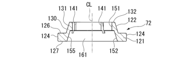
- the second nut 72 has a second main body portion 121 and a second protrusion portion 122.
- the second main body portion 121 has an annular shape.
- the second main body portion 121 has a pair of second arcuate surfaces 124 and a pair of second notch surfaces 125 on the outer circumferential side.
- the pair of second arcuate surface portions 124 are both in the shape of a portion of a cylindrical surface having the same diameter.
- the pair of second arcuate surface portions 124 have central axes aligned with each other. This central axis is defined as the central axis of the second nut 72.
- the radius of the second arcuate surface portion 124 is smaller than the radius of the first arcuate surface portion 84, as shown in FIG.
- the thickness of the second main body portion 121 is thinner than the thickness of the first main body portion 81 of the first nut 71 .
- a pair of second notch surfaces 125 shown in FIG. 10 have a planar shape parallel to the central axis of the second nut 72. As shown in FIG. The pair of second notch surfaces 125 are parallel to each other. The distances between the pair of second notch surfaces 125 from the central axis of the second nut 72 are the same. As shown in FIG. 11, the second main body portion 121 has an end surface portion 126 on one end side in the axial direction of the second nut 72, and an end surface portion 127 on the other end side in the axial direction of the second nut 72. have. Both the end surface portion 126 and the end surface portion 127 have a planar shape that extends perpendicularly to the central axis of the second nut 72.
- the second protruding portion 122 has an annular shape as a whole, and protrudes from the end surface portion 126 along the axial direction of the second nut 72 to the side opposite to the end surface portion 127.
- the second protruding portion 122 has a second outer slope portion 130 (second slope portion) on the outer peripheral side.
- the second outer inclined portion 130 has a tapered outer surface portion 131 facing radially outward.
- the tapered outer surface portion 131 has a tapered surface coaxial with the center axis of the second nut 72 . The diameter of the tapered outer surface portion 131 becomes smaller as the distance from the end surface portion 126 in the axial direction of the second nut 72 increases.
- the second outer inclined portion 130 is inclined such that the diameter thereof becomes smaller as the distance from the second main body portion 121 increases in the axial direction of the second nut 72.
- the tapered outer surface portion 131 has a maximum outer diameter smaller than the outer diameter of the pair of second arcuate surface portions 124 .
- the taper of the tapered outer surface portion 131 is equivalent to the taper of the tapered inner surface portion 105 of the first nut 71 shown in FIG.
- the minimum outer diameter of the tapered outer surface portion 131 shown in FIG. 11 is smaller than the maximum inner diameter of the tapered inner surface portion 105 shown in FIG. 8.
- the maximum outer diameter of the tapered outer surface portion 131 shown in FIG. 11 is larger than the maximum inner diameter of the tapered inner surface portion 105 shown in FIG. 8.
- the second protruding portion 122 has a tip end surface portion 132 on the opposite side of the second main body portion 121 in the axial direction of the second nut 72.
- the tip surface portion 132 extends inward in the radial direction of the second nut 72 from the edge portion of the tapered outer surface portion 131 on the opposite side to the end surface portion 126 in the axial direction of the second nut 72 .
- the tip surface portion 132 has a planar shape that extends perpendicularly to the central axis of the second nut 72 .
- the second nut 72 has an end surface portion 127 at one end in the axial direction, and a tip surface portion 132 at the other end in the axial direction.
- the second protrusion 122 is provided with a plurality of notches 141, specifically four cutouts 141.
- Each of these notches 141 passes through the second protrusion 122 in the radial direction of the second protrusion 122 over the entire length of the second protrusion 122 in the axial direction.
- the notch 141 is formed in the second protrusion 122 so as to be recessed from the tip end surface section 132 to the end surface section 126. Therefore, the second outer inclined portion 130 is provided with a plurality of notches 141 that traverse the second outer inclined portion 130 in the radial direction.
- the plurality of notches 141 are arranged at equal intervals in the circumferential direction of the second protrusion 122.
- the second protrusion 122 is divided into four equal parts by a plurality of cutouts 141, specifically four cutouts 141.
- the second outer inclined portion 130 is also divided into four equal parts by a cutout portion 141.
- the second nut 72 has a second female threaded portion 151 (female threaded portion) and a second inner inclined portion 152 on the inner peripheral side.
- the second internally threaded portion 151 of the second internally threaded portion 151 and the second internally inclined portion 152 is disposed on the distal end surface portion 132 side, and the second internally inclined portion 152 is disposed on the end surface portion 127 side. It is located in In the axial direction of the second nut 72, the second female threaded portion 151 is entirely disposed on the second protrusion 122. Therefore, the second female threaded portion 151 is also provided with a plurality of notches 141, specifically four notches 141.
- Each of these notches 141 traverses the second female threaded portion 151 in the radial direction over the entire length of the second female threaded portion 151 in the axial direction.
- the second female threaded portion 151 is also divided into four equal parts by the cutout portion 141.
- a portion of the second inner inclined portion 152 is disposed on the second protrusion 122, and the rest is entirely disposed on the second main body portion 121.
- the second female threaded portion 151 is a spiral parallel thread centered on the central axis of the second nut 72, and is screwed into the rod male threaded portion 61 of the rod 50 as shown in FIG.
- the second inner inclined portion 152 has a tapered inner surface portion 155.
- the tapered inner surface portion 155 extends from the thread bottom position of the second female threaded portion 151 on the end surface portion 127 side toward the end surface portion 127 in the axial direction of the second nut 72 and is connected to the end surface portion 127 .
- the tapered inner surface portion 155 is a tapered surface centered on the central axis of the second nut 72, and the diameter increases as the distance from the second female thread portion 151 increases in the axial direction of the second nut 72.
- the second nut 72 has a through hole 161 that penetrates the second nut 72 in the axial direction of the second nut 72 at its radial center.
- the through hole 161 is formed on the radially inner side of the second female threaded portion 151 and on the radially inner side of the second inner inclined portion 152 .
- the rod 50 includes the regulating member 65, the intervening disk 66, and the plurality of valve disks 67, with the mounting shaft portions 56 inserted inside each in the radial direction.
- a piston 45, a plurality of valve disks 68, an intervening disk 69, and a regulating member 70 are provided to be stacked on the main shaft portion 55 in this order.
- the rod male threaded portion 61 protrudes beyond the regulating member 70 to the side opposite to the piston 45.
- the first nut 71 is screwed onto the male threaded portion 61 of the rod.
- the first nut 71 is attached to the rod male threaded portion 61 at the first female threaded portion 101 with the first protruding portion 82 placed ahead of the first main body portion 81. Screwed together.
- the first nut 71 is then tightened with a predetermined tightening torque after the distal end surface portion 92 contacts the regulating member 70 in surface contact. Then, the first nut 71 sandwiches the parts from the regulating member 65 to the regulating member 70, including the piston 45 shown in FIG. 1, with the axial end surface 57 of the main shaft portion 55.
- the first nut 71 arranged in this manner is in a state where it is screwed into the rod male threaded portion 61 of the rod 50.
- the first nut 71 is inclined at the end opposite to the piston 45 in the axial direction so as to be separated from the male rod threaded portion 61 in the radial direction, as shown in FIGS. 4 and 5. It has a first inner inclined portion 102 .
- the second nut 72 is screwed into a portion of the male rod threaded portion 61 of the mounting shaft portion 56 that protrudes from the first nut 71 toward the opposite side of the regulating member 70 .
- the second nut 72 is screwed onto the rod male threaded portion 61 at the second female threaded portion 151 in such a direction that the second protruding portion 122 is located ahead of the second main body portion 121 .
- the second outer inclined portion 130 and the second female threaded portion 151 of the second protruding portion 122 enter inside the first inner inclined portion 102 of the first nut 71, and the second outer inclined portion 130 of the second outer inclined portion 130 is inserted.
- the tapered outer surface portion 131 contacts the tapered inner surface portion 105 of the first inner inclined portion 102 in surface contact, it is tightened with a predetermined tightening torque.
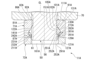
- the second nut 72 is arranged so as to sandwich the first nut 71, the regulating member 70, the intervening disk 69, and the plurality of valve disks 68 between it and the piston 45, as shown in FIG. In this state, as shown in FIG. Because of this, the second female threaded portion 151 that is screwed into the rod male threaded portion 61 is disposed between the first nut 71 and the rod male threaded portion 61 in the radial direction. In other words, the rod male threaded portion 61, the second female threaded portion 151, the second outer inclined portion 130, and the first inner inclined portion 102 overlap each other in the axial direction of the rod 50.
- the second nut 72 has a second outer inclined portion 130 formed on the radial outer periphery of the second female threaded portion 151, which at least partially abuts the first inner inclined portion 102.
- the second outer inclined portion 130 is formed due to the inclination of the tapered outer surface portion 131 of the second nut 72 and the tapered inner surface portion 105 of the first nut 71 that abuts the second nut 72. It is pushed radially inward by the first inner inclined portion 102 . Then, the second protrusion 122 elastically deforms inward in the radial direction while narrowing the width of the notch 141 in the circumferential direction.
- the second outer inclined portion 130 and the second female threaded portion 151 overlap each other in the axial direction.
- the second outer inclined portion 130 is pushed radially inward by the first inner inclined portion 102 of the first nut 71 and deforms.
- the second female threaded portion 151 is also pushed radially inward and deformed, and is pressed against the rod male threaded portion 61 and comes into close contact with the rod male threaded portion 61.
- the base valve 30 includes a valve body 25, an intervening disc 182, a plurality of valve discs 183, a disc valve 184, an intervening disc 185, a regulating member 186, a pin member 187, have.
- the pin member 187 is a rod-shaped member and has a pin flange portion 191, a pin shaft portion 192, and an engaging portion 193.
- the pin flange portion 191 has a disk shape.
- the outer peripheral surface of the pin flange portion 191 is a cylindrical surface.
- the pin shaft portion 192 is rod-shaped, specifically cylindrical, and has an outer diameter smaller than the outer diameter of the pin flange portion 191. Therefore, the pin flange portion 191 has a flange shape with an outer diameter larger than that of the pin shaft portion 192.
- the pin shaft portion 192 protrudes from an axial end surface 195 at one end of the pin flange portion 191 in the axial direction.
- the engaging portion 193 has a substantially disk shape, and its outer diameter is larger than the outer diameter of the pin shaft portion 192.
- the regulating member 186, intervening disks 182, 185, valve disk 183, disk valve 184, and valve body 25 are all circular with holes.
- the pin member 187 has an intervening disk 182, a plurality of valve disks 183, a valve body 25, and a pin shaft portion 192, which has not yet been formed with an engaging portion 193, fitted inside each in the radial direction.
- a disc valve 184, an intervening disc 185, and a regulating member 186 are provided to be stacked on the pin flange portion 191 in this order. In this state, the portion of the pin shaft portion 192 that protrudes beyond the regulating member 186 is crimped to form the engaging portion 193.
- the intervening disk 182 the plurality of valve disks 183, the valve body 25, the disk valve 184, the intervening disk 185, and the regulating member 186 are clamped by the pin flange portion 191 and the engaging portion 193 at least on their respective inner peripheral sides. Ru.
- a passage 197 and a passage 198 are formed in the valve body 25. Both the passage 197 and the passage 198 pass through the valve body 25 in the axial direction of the valve body 25. The passages 197 and 198 can communicate the second chamber 47 and the reservoir chamber 18.
- the plurality of valve disks 183 constitute a disk valve 201.
- the disc valve 201 is provided on the bottom 22 side of the valve body 25 in the axial direction.
- the disc valve 201 has an annular shape and closes the passage 197 by coming into contact with the valve body 25.
- the disc valve 184 is provided on the opposite side of the valve body 25 from the bottom 22 in the axial direction.
- the disc valve 184 has an annular shape and closes the passage 198 by coming into contact with the valve body 25.
- the outer diameter of the intervening disk 182 is smaller than the outer diameter of the disk valve 201.
- the intervening disk 185 has an outer diameter smaller than the outer diameter of the disk valve 184.
- the outer diameter of the regulating member 186 is larger than the outer diameter of the intervening disk 185 and smaller than the outer diameter of the disk valve 201.
- the regulating member 186 contacts the engaging portion 193 of the pin member 187.
- the rod 50 moves to the contraction side and the piston 45 moves in a direction to narrow the second chamber 47.
- the base valve 30 opens the disc valve 201 to open the passage 197 and drain the oil L in the second chamber 47. It will flow into the reservoir chamber 18.
- the disc valve 201 generates a damping force.
- the pin flange portion 191 of the pin member 187 restricts further deformation of the disc valve 201 in the opening direction by coming into contact with the opening disc valve 201 .
- the rod 50 moves to the extension side and the piston 45 moves to the first chamber 46 side.
- the disc valve 184 opens and the passage 198 opens, allowing the oil L in the reservoir chamber 18 to flow into the second chamber 47 . It will flow.
- the disc valve 184 allows the oil L to flow from the reservoir chamber 18 into the second chamber 47 without substantially generating damping force.
- Disc valve 184 is a suction valve.
- the restricting member 186 restricts further deformation of the disc valve 184 in the opening direction by coming into contact with the disc valve 184 that is opening.
- a portion of the rod 50 protruding from the cylinder 14 is connected to the vehicle body side of the vehicle, and the cylinder 14 is connected to the vehicle wheel side to generate a damping force against movement of the wheel relative to the vehicle body.
- Patent Document 1 discloses a first nut having a small diameter portion having a tapered surface whose diameter becomes smaller toward the tip side, and a second nut having a tapered fitting surface that fits into the small diameter portion.
- a nut locking device is disclosed. In this locking device, when the amount of engagement between the tapered surface of the first nut and the engagement surface of the second nut increases and the engagement becomes deeper, the threaded portion of the second nut deforms to expand in the radial direction. This may cause loosening.
- the shock absorber 11 of the first embodiment is arranged such that the piston 45 and the like are sandwiched between the main shaft portion 55 of the rod 50, and includes a first nut 71 that is screwed into the rod male threaded portion 61, and a first A second nut 72 is arranged to sandwich the nut 71 between the piston 45 and the like.
- the first nut 71 has a first inner inclined portion 102 that is inclined away from the rod male threaded portion 61 at the end opposite to the piston 45 .
- a second female threaded portion 151 that is threadedly engaged with the rod male threaded portion 61 is disposed between the first nut 71 and the rod male threaded portion 61, and a first A second outer inclined portion 130 is formed which at least partially abuts the inner inclined portion 102 . Therefore, when the second outer inclined part 130 is pushed radially inward and deformed by the first inner inclined part 102 as the second protruding part 122 continues to enter the first nut 71, the second female threaded part 151 is also deformed. It is pushed radially inward and deformed, and is pressed against the rod male threaded portion 61 and comes into close contact.
- the shock absorber 11 employs a locking structure having such a first nut 71 and a second nut 72, it suppresses the occurrence of loosening of the first nut 71 and the second nut 72 with respect to the rod male threaded portion 61. be able to.
- first nut 71 and the second nut 72 having such a structure can be manufactured without significantly changing the conventional processing method. Therefore, cost increases can be suppressed. For example, an increase in cost can be suppressed compared to the case of using an eccentric nut.
- first nut 71 and the second nut 72 having such a structure are not plastically deformed and can be reused. Therefore, compared to the case of using a caulking nut, an increase in cost during maintenance can be suppressed. Further, there is no need to discard parts as in the case of using a caulking nut. Further, contamination that occurs when applying a screw locking agent can be suppressed.
- the shock absorber 11 also includes a regulating member 65, an intervening disc 66, a plurality of valve discs 67, a piston 45, a plurality of valve discs 68, an intervening disc 69, and a regulating member, which are fastened by the first nut 71.
- the second nut 72 can be fastened without affecting the specified tightening force (axial force) of the nut 70.
- the shock absorber 11 is a disassembled type shock absorber, and in such a disassembled type shock absorber, the locking structure having the first nut 71 and the second nut 72 has less variation in the axial force at the time of installation. Damping force is reproducible upon reassembly.
- the shock absorber 11 includes a disc valve 77 disposed between the main shaft portion 55 and the piston 45 and a disc valve 78 disposed between the piston 45 and the first nut 71. Therefore, variations in the axial force when the disc valves 77 and 78 are attached to the rod 50 can be suppressed. Therefore, variations in damping force characteristics due to the disc valves 77 and 78 can be suppressed, and stable damping force characteristics can be obtained. Further, even if the first nut 71 and the second nut 72 are removed from the rod male threaded portion 61 and then reattached to the rod male threaded portion 61, the damping force characteristics of the disc valves 77 and 78 are reproducible.
- the locking structure having the first nut 71 and the second nut 72 is particularly effective for a type of shock absorber 11 having disc valves 77 and 78 whose damping force characteristics vary due to variations in the axial force of the screws.
- the second outer inclined part 130 is provided with a notch 141 that radially crosses the second outer inclined part 130, so that the second outer inclined part 130 is radially inward. Easy to deform. Therefore, when the second female threaded portion 151 is also pushed inward in the radial direction, it is easily deformed, and is well pressed against the rod male threaded portion 61 and comes into close contact with the rod male threaded portion 61.
- the shock absorber 11 is provided with a plurality of notches 141, the second outer inclined portion 130 is more easily deformed inward in the radial direction. Therefore, when the second female threaded portion 151 is also pushed inward in the radial direction, it becomes more easily deformed, and is well pressed against the rod male threaded portion 61 and comes into close contact.
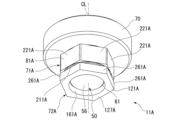
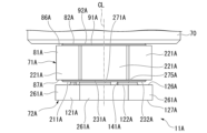
- the shock absorber 11A of the second embodiment has a first nut 71A that is partially different from the first nut 71 instead of the first nut 71, as shown in FIGS. 12 to 15. Furthermore, the shock absorber 11A includes a second nut 72A, which is partially different from the second nut 72, in place of the second nut 72.
- the first nut 71A and the second nut 72A are also screwed into a rod male threaded portion 61 that protrudes from the regulating member 70 of the mounting shaft portion 56 of the rod 50 on the opposite side of the piston 45 (see FIG. 1).
- the first nut 71A is arranged on the regulating member 70 side
- the second nut 72A is arranged on the opposite side from the regulating member 70.
- the first nut 71A also includes a regulating member 65 (see FIG. 1), an intervening disk 66 (see FIG. 1), a plurality of valve disks 67 (see FIG. 1), a piston 45 (see FIG.
- the second nut 72A is configured to sandwich the first nut 71A between the piston 45 (see FIG. 1), the plurality of valve disks 68 (see FIG. 1), the intervening disk 69 (see FIG. 1), and the regulating member 70.
- the first nut 71A has a first main body portion 81A and a protrusion 82A at one end, as shown in FIGS. 16 to 18, and a protrusion 211A at the other end, as shown in FIGS. 16 and 18. are doing.
- the first main body portion 81A has a hexagonal columnar outer shape as shown in FIGS. 16 and 17.
- the first main body portion 81A has six identically shaped surface portions 221A on the outer peripheral side. All of the six surface portions 221A have a rectangular shape, and are arranged so that the entire outer surface shape of a regular hexagonal prism is formed.
- the center axis of a regular hexagonal prism whose outer surface is formed by six surface portions 221A is the center axis of the first nut 71A.
- the six surface portions 221A are all planar parallel to the central axis of the first nut 71A, and the distances from the central axis are the same.
- the first main body portion 81A has an end surface portion 86A on one end side in the axial direction of the first nut 71A, and an end surface portion 87A on the other end side in the axial direction of the first nut 71A. have. Both the end surface portion 86A and the end surface portion 87A have a planar shape that extends perpendicularly to the central axis of the first nut 71A.
- the one end protrusion 82A has an annular shape and protrudes from the end surface 86A along the axial direction of the first nut 71A to the opposite side to the end surface 87A.
- the one end protruding portion 82A has a cylindrical surface portion 91A on the outer peripheral side.
- the cylindrical surface portion 91A has a cylindrical surface shape that is coaxial with the center axis of the first nut 71A. As shown in FIG. 17, the radius of the cylindrical surface portion 91A is equal to the distance from the central axis of the first nut 71A to the surface portion 221A. As shown in FIGS.
- the one end protruding portion 82A has a tip end surface portion 92A on the opposite side from the first main body portion 81A in the axial direction of the first nut 71A.
- the tip surface portion 92A has a planar shape that extends perpendicularly to the central axis of the first nut 71A.
- the other end protruding portion 211A shown in FIG. 18 has an annular shape and protrudes from the end surface portion 87A along the axial direction of the first nut 71A toward the side opposite to the end surface portion 86A.
- the other end protruding portion 211A has a cylindrical surface portion 231A on the outer peripheral side.
- the cylindrical surface portion 231A has a cylindrical surface shape that is coaxial with the center axis of the first nut 71A.
- the radius of the cylindrical surface portion 231A is equivalent to the distance from the central axis of the first nut 71A to the surface portion 221A shown in FIG. 17. As shown in FIG.
- the other end protruding portion 211A has a tip surface portion 232A on the opposite side of the first main body portion 81A in the axial direction of the first nut 71A.
- the tip surface portion 232A has a planar shape that extends perpendicularly to the central axis of the first nut 71A.
- the first nut 71A has a tip surface portion 92A at one end in the axial direction, and a tip surface portion 232A at the other end in the axial direction.
- the first nut 71A has a first internal threaded portion 101A, a first inner inclined portion 102A (first inclined portion), an intermediate inner circumferential portion 241A, and an inner protruding portion 242A on the inner circumferential side. There is. In the axial direction of the first nut 71A, the first female threaded portion 101A, the first inner inclined portion 102A, the intermediate inner peripheral portion 241A, and the inner peripheral protrusion 242A are arranged in this order from the distal end surface portion 92A side.
- first inner inclined portion 102A is entirely disposed in the first main body portion 81A.
- intermediate inner peripheral portion 241A is entirely disposed in the first main body portion 81A.
- a part of the inner peripheral protrusion 242A is disposed on the other end protrusion 211A, and the rest is entirely disposed on the first main body 81A.
- the first female screw portion 101A is a spiral parallel screw centered on the central axis of the first nut 71A, and is screwed into the rod male screw portion 61 of the rod 50 as shown in FIGS. 14 and 15.
- the first inner inclined portion 102A has a tapered inner surface portion 105A facing radially inward.
- the tapered inner surface portion 105A extends from the thread top position on the tip surface portion 232A side of the first female thread portion 101A toward the tip surface portion 232A side in the axial direction of the first nut 71A.
- the tapered inner surface portion 105A is a tapered surface centered on the central axis of the first nut 71A, and becomes larger in diameter as the distance from the first female threaded portion 101A increases in the axial direction of the first nut 71A.
- the intermediate inner peripheral portion 241A has a cylindrical inner surface portion 245A facing radially inward.
- the cylindrical inner surface portion 245A extends from the edge of the tapered inner surface portion 105A on the distal end surface portion 232A side toward the distal end surface portion 232A side in the axial direction of the first nut 71A.
- the cylindrical inner surface portion 245A has a cylindrical surface shape centered on the central axis of the first nut 71A.
- the inner peripheral protrusion 242A has a locking surface 251A, an inner end surface 252A, and a chamfered portion 253A.
- the locking surface portion 251A extends inward in the radial direction of the first nut 71A from the end edge of the cylindrical inner surface portion 245A on the distal end surface portion 232A side in the axial direction of the first nut 71A.
- the locking surface portion 251A has a planar shape that extends perpendicularly to the central axis of the first nut 71A.
- the inner end surface portion 252A extends from the inner end edge of the locking surface portion 251A in the radial direction of the first nut 71A toward the tip surface portion 232A along the axial direction of the first nut 71A.
- the inner end surface portion 252A has a cylindrical surface shape centered on the central axis of the first nut 71A.
- the chamfered portion 253A extends from the end position of the inner end surface portion 252A on the distal end surface portion 232A side toward the distal end surface portion 232A side in the axial direction of the first nut 71A, and is connected to the distal end surface portion 232A.
- the chamfered portion 253A is a tapered surface centered on the central axis of the first nut 71A, and becomes larger in diameter as it moves away from the inner end surface portion 252A in the axial direction of the first nut 71A.
- the first nut 71A has a through hole 111A in its radial center that passes through the first nut 71A in the axial direction of the first nut 71A.
- the through hole 111A has a radially inner side of the first female threaded portion 101A, a radially inner side of the first inner inclined portion 102A, a radially inner side of the intermediate inner peripheral portion 241A, and a radially inner side of the inner peripheral protrusion 242A. , is formed by.
- the second nut 72A has a second main body portion 121A and a second protruding portion 122A.
- the second main body portion 121A has a hexagonal columnar outer shape as shown in FIGS. 19 and 20.
- the second main body portion 121A has six identically shaped surface portions 261A on the outer peripheral side. All of the six surface portions 261A have a rectangular shape, and are arranged so that the entire outer surface shape of a regular hexagonal prism is formed.
- the center axis of a regular hexagonal prism whose outer surface is formed by six surface portions 261A is the center axis of the second nut 72A.
- the six surface portions 261A are all planar parallel to the central axis of the second nut 72A, and the distances from the central axis are the same.
- the distance of the surface portion 261A from the central axis of the second nut 72A is slightly larger than the distance of the surface portion 221A of the first nut 71A from the central axis of the second nut 72A.
- the thickness of the second main body portion 121A is thinner than the thickness of the first main body portion 81A of the first nut 71A. As shown in FIG.
- the second main body portion 121A has an end surface portion 126A on one end side in the axial direction of the second nut 72A, and an end surface portion 127A on the other end side in the axial direction of the second nut 72A. have. Both the end surface portion 126A and the end surface portion 127A have a planar shape that extends perpendicularly to the central axis of the second nut 72A.
- the second protruding portion 122A has an annular shape as a whole, and protrudes from the end surface portion 126A along the axial direction of the second nut 72A on the opposite side to the end surface portion 127A.
- the second protruding portion 122A has a proximal outer circumferential portion 271A and an outer circumferential protruding portion 272A on the outer circumferential side.
- the proximal outer peripheral portion 271A has a cylindrical outer surface portion 275A facing radially outward.
- the cylindrical outer surface portion 275A extends from the inner peripheral edge of the end surface portion 126A of the second main body portion 121A toward the side opposite to the end surface portion 127A along the axial direction of the second nut 72A.
- the cylindrical outer surface portion 275A has a cylindrical surface shape centered on the central axis of the second nut 72A.
- the outer peripheral protrusion 272A has a locking surface 281A, an outer end surface 282A, and a tapered outer surface 131A.
- the locking surface portion 281A extends outward in the radial direction of the second nut 72A from the end edge of the cylindrical outer surface portion 275A on the opposite side to the end surface portion 126A in the axial direction of the second nut 72A.
- the locking surface portion 281A has a planar shape that extends perpendicularly to the central axis of the second nut 72A.
- the outer end surface portion 282A extends from the outer end edge of the locking surface portion 281A in the radial direction of the second nut 72A to the side opposite to the end surface portion 126A along the axial direction of the second nut 72A.
- the outer end surface portion 282A has a cylindrical surface shape centered on the central axis of the second nut 72A.
- the radius of the outer end surface portion 282A is smaller than the distance of the surface portion 261A from the central axis of the second nut 72A.
- the tapered outer surface portion 131A extends in the direction opposite to the end surface portion 126A from the edge portion of the outer end surface portion 282A of the second nut 72A in the axial direction on the opposite side to the end surface portion 126A.
- the tapered outer surface portion 131A has a tapered surface coaxial with the center axis of the second nut 72A. The diameter of the tapered outer surface portion 131A becomes smaller as the distance from the end surface portion 126A increases in the axial direction of the second nut 72A.
- the second protruding portion 122A has a second outer slope portion 130A (second slope portion).
- the tapered outer surface portion 131A is provided on this second outer inclined portion 130A. Therefore, the second outer inclined portion 130A is inclined so that the diameter thereof becomes smaller as the distance from the second main body portion 121A increases in the axial direction of the second nut 72A.
- the taper of the tapered outer surface portion 131A is equivalent to the taper of the tapered inner surface portion 105A of the first nut 71A shown in FIG.
- the minimum outer diameter of the tapered outer surface portion 131A shown in FIG. 21 is smaller than the maximum inner diameter of the chamfered portion 253A shown in FIG. 18.
- the outer diameter of the outer end surface portion 282A is larger than the inner diameter of the inner end surface portion 252A shown in FIG.
- the outer diameter of the outer end surface portion 282A shown in FIG. 21 is smaller than the inner diameter of the cylindrical inner surface portion 245A shown in FIG. 18.
- the second protruding portion 122A has a tip end surface portion 132A on the opposite side from the second main body portion 121A in the axial direction of the second nut 72A.
- the tip surface portion 132A extends inward in the radial direction of the second nut 72A from the edge portion of the tapered outer surface portion 131A on the opposite side to the end surface portion 126A in the axial direction of the second nut 72A.
- the tip surface portion 132A has a planar shape that extends perpendicularly to the central axis of the second nut 72A.
- the second nut 72A has an end surface portion 127A at one end in the axial direction, and a tip surface portion 132A at the other end in the axial direction.
- the second protrusion 122A is provided with a plurality of, specifically five, notches 141A.
- Each of these notches 141A passes through the second protrusion 122A in the radial direction of the second protrusion 122A over the entire axial length of the second protrusion 122A.
- the notch 141A is formed in the second protrusion 122A so as to be recessed from the tip end surface portion 132A to the end surface portion 126A. Therefore, the second outer inclined portion 130A is provided with a plurality of notches 141A that radially cross the second outer inclined portion 130A.
- the plurality of notches 141A are arranged at equal intervals in the circumferential direction of the second protrusion 122A.
- the second protrusion 122A is divided into five equal parts by a plurality of notches 141A, specifically, five notches.
- the second outer inclined portion 130A is also divided into five equal parts by the cutout portion 141A.
- the second nut 72A has a second female threaded portion 151A (female threaded portion) and a cylindrical inner circumferential portion 291A on the inner circumferential side.
- the second female threaded part 151A of the second female threaded part 151A and the cylindrical inner peripheral part 291A is arranged on the tip surface part 132A side, and the cylindrical inner peripheral part 291A is arranged on the end surface part 127A side. It is located in In the axial direction of the second nut 72A, the second female threaded portion 151A is entirely disposed on the second protrusion 122A.
- the second female screw portion 151A is also provided with a plurality of cutout portions 141A, specifically five cutout portions. Each of these notches 141A radially crosses the second female threaded portion 151A over the entire axial length of the second female threaded portion 151A.
- the second female screw portion 151A is also divided into five equal parts by the cutout portion 141A.
- a portion of the cylindrical inner peripheral portion 291A is disposed on the second protrusion 122A, and the rest is entirely disposed on the second main body portion 121A.
- the second female threaded portion 151A is a spiral parallel thread centered on the central axis of the second nut 72A, and is screwed into the rod male threaded portion 61 of the rod 50 as shown in FIG.
- the cylindrical inner circumferential portion 291A has a cylindrical inner circumferential surface 292A facing inward in the radial direction of the second nut 72A.
- the cylindrical inner circumferential surface 292A extends from a position outside the second nut 72A in the radial direction from the thread bottom position on the end surface 127A side of the second female threaded portion 151A in the axial direction of the second nut 72A. It extends and is connected to the end face portion 127A.
- the cylindrical inner circumferential surface 292A has a cylindrical surface shape centered on the central axis of the second nut 72A.
- the second nut 72A has a through hole 161A at its radial center that passes through the second nut 72A in the axial direction of the second nut 72A.
- the through hole 161A is formed on the radially inner side of the second female threaded portion 151A and on the radially inner side of the cylindrical inner peripheral portion 291A.
- the second nut 72A is previously engaged with the first nut 71A before being screwed onto the rod 50. That is, the second nut 72A is pushed into the through hole 111A of the first nut 71A from the chamfered portion 253A side, with the second protruding portion 122A of the second main body portion 121A and the second protruding portion 122A leading. It will be done. Then, the second outer inclined portion 130A of the second protruding portion 122A of the second nut 72A forms a chamfered portion due to the inclination of its tapered outer surface portion 131A and the chamfered portion 253A of the first nut 71A that comes into contact with the tapered outer surface portion 131A.
- the second protrusion 122A elastically deforms inward in the radial direction while narrowing the width of the notch 141A in the circumferential direction.
- the entire outer protrusion 272A of the second nut 72A is located closer to the first female threaded part 101A than the inner protrusion 242A of the first nut 71A in the axial direction, the inner protrusion The radially inward pressing by 242A is released, and the radially outward direction returns. In this way, the second protrusion 122A engages with the first nut 71A.
- the diameter of the outer end surface portion 282A of the second nut 72A becomes larger than the diameter of the inner end surface portion 252A. Therefore, the second nut 72A is prevented from coming off from the first nut 71A by the locking surface portion 281A coming into contact with the locking surface portion 251A.
- the inner protrusion 242A of the first nut 71A and the outer protrusion 272A of the second nut 72A prevent the first nut 71A and the second nut 72A from moving in the axial direction toward the disengagement side.
- a stopper portion 301A is configured to suppress this.
- the rod 50 has a regulating member 65 (see FIG. 1) with its mounting shaft portion 56 inserted inside each in the radial direction.
- an intervening disk 66 see FIG. 1
- a plurality of valve disks 67 see FIG. 1
- a piston 45 see FIG. 1
- a plurality of valve disks 68 see FIG. 1
- an intervening disk 69 see FIG. 1
- a regulating member 70 see FIG. 1
- the first nut 71A and second nut 72A which were previously engaged as described above, are screwed into this rod male threaded portion 61.
- the first nut 71A is screwed into the rod male threaded portion 61 at the first female threaded portion 101A with the one end protruding portion 82A placed ahead of the first main body portion 81A.
- the second nut 72A is screwed into the rod male threaded portion 61 at the second female threaded portion 151A.
- the first nut 71A is screwed onto the rod male threaded portion 61 until the distal end surface portion 92A abuts the regulating member 70 in surface contact.
- the second nut 72A is screwed onto the rod male threaded portion 61, for example, until the tapered outer surface portion 131A abuts the tapered inner surface portion 105A of the first nut 71A in surface contact.
- the first nut 71A is tightened with a predetermined tightening torque.
- the first nut 71A moves the parts from the regulating member 65 (see FIG. 1) including the piston 45 (see FIG. 1) to the regulating member 70 onto the axial end surface 57 (see FIG.
- the first nut 71A arranged in this manner is in a state where it is screwed into the rod male threaded portion 61 of the rod 50.
- the first nut 71A has a rod male threaded portion 61 in the radial direction at the end opposite to the piston 45 (see FIG. 1) in the axial direction, as shown in FIGS. 14 and 15. It has a first inner inclined part 102A which is inclined so as to be spaced apart.
- the second nut 72A is tightened with a predetermined tightening torque.
- the second nut 72A connects the first nut 71A, the regulating member 70, the intervening disk 69 (see FIG. 1), and the plurality of valve disks 68 (see FIG. 1) with the piston 45 (see FIG. 1). It is arranged so that it is sandwiched between.
- the second nut 72A has the second outer inclined portion 130A and the second female threaded portion 151A of the second protruding portion 122A inside the first inner inclined portion 102A of the first nut 71A. I'm getting into it.
- a second female threaded portion 151A that is screwed into the rod male threaded portion 61 is disposed between the first nut 71A and the rod male threaded portion 61 in the radial direction.
- the rod male threaded portion 61, the second female threaded portion 151A, the second outer inclined portion 130A, and the first inner inclined portion 102A overlap each other in the axial direction of the rod 50.
- a part of the second outer inclined part 130A on the radial outer circumference of the second female threaded part 151A is in contact with the first inner inclined part 102A of the first nut 71A.
- the second outer inclined portion 130A may be entirely in contact with the first inner inclined portion 102A. Therefore, in the second nut 72A, a second outer inclined portion 130A, which at least partially abuts the first inner inclined portion 102A, is formed on the radial outer circumference of the second female screw portion 151A.
- the second outer inclined portion 130A is formed due to the inclination of the tapered outer surface portion 131A of the second nut 72A and the tapered inner surface portion 105A of the first nut 71A that abuts the second nut 72A. It is pushed radially inward by the first inner inclined portion 102A. Then, the second protrusion 122A elastically deforms inward in the radial direction while narrowing the width of the notch 141A in the circumferential direction.
- the second outer inclined portion 130A and the second female screw portion 151A overlap each other in the axial direction.
- the second protruding portion 122A moves into the first nut 71A
- the second outer inclined portion 130A is pushed radially inward and deformed by the first inner inclined portion 102A of the first nut 71A.
- the second female threaded portion 151A is also pushed radially inward and deformed, and is pressed against the rod male threaded portion 61 and comes into close contact with the rod male threaded portion 61.
- the shock absorber 11A of the second embodiment is arranged such that a piston 45 (see FIG. 1) and the like are sandwiched between the main shaft portion 55 (see FIG. 1) of a rod 50, and a first It has a nut 71A and a second nut 72A arranged so as to sandwich the first nut 71A between the piston 45 (see FIG. 1) and the like.
- the first nut 71A has a first inner inclined portion 102A inclined away from the rod male threaded portion 61 at the end opposite to the piston 45 (see FIG. 1).
- a second female threaded portion 151A that is threadedly engaged with the rod male threaded portion 61 is disposed between the first nut 71A and the rod male threaded portion 61, and a first A second outer inclined portion 130A is formed which at least partially abuts the inner inclined portion 102A. Therefore, when the second outer inclined portion 130A is pushed radially inward by the first inner inclined portion 102A and deforms due to the progress of the second protruding portion 122A entering the first nut 71A, the second female threaded portion 151A is also deformed. It is pushed radially inward and deformed, and is pressed against the rod male threaded portion 61 and comes into close contact. In other words, the deeper the second nut 72A is fitted into the first nut 71A, the stronger the screw fastening of the second nut 72A to the rod male threaded portion 61 becomes.
- the shock absorber 11A employs a locking structure having such a first nut 71A and a second nut 72A, the occurrence of loosening of the first nut 71A and the second nut 72A with respect to the rod male threaded portion 61 is suppressed. be able to. Therefore, the buffer 11A can provide the same effects as the buffer 11 of the first embodiment.
- the first nut 71A and the second nut 72A are provided with a stopper portion 301A for suppressing movement in the axial direction. Therefore, even if the second nut 72A becomes loose with respect to the rod male threaded portion 61, the first nut 71A can prevent the second nut 72A from falling off from the rod male threaded portion 61. Moreover, since the shock absorber 11A is provided with the stopper portion 301A, the first nut 71A and the second nut 72A can be assembled in advance and fastened to the rod male threaded portion 61 almost simultaneously. Therefore, it is possible to reduce the number of assembly steps.
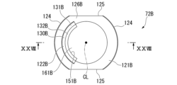
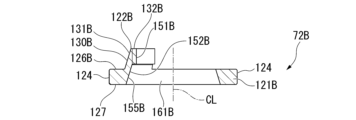
- a second nut 72B that is partially different from the second nut 72 is provided instead of the second nut 72.
- the second nut 72B is also screwed together with the first nut 71 into a rod male threaded portion 61 that protrudes from the regulating member 70 of the mounting shaft portion 56 of the rod 50 on the opposite side of the piston 45 (see FIG. 1).
- the first nut 71 is disposed on the regulating member 70 side
- the second nut 72B is disposed on the opposite side from the regulating member 70.
- the second nut 72B is configured to sandwich the first nut 71 between the piston 45 (see FIG. 1), the plurality of valve disks 68 (see FIG. 1), the intervening disk 69 (see FIG. 1), and the regulating member 70. will be placed in
- the second nut 72B has a second main body portion 121B, which is partially different from the second main body portion 121, instead of the second main body portion 121.
- the second main body portion 121B has an end surface portion 126B having a partially different shape from the end surface portion 126 instead of the end surface portion 126.
- the central axis of the pair of second circular arcuate surfaces 124 of the second main body portion 121B is the central axis of the second nut 72B.
- the end surface portion 126B has a planar shape that extends perpendicularly to the central axis of the second nut 72B.
- the second nut 72B has a second protrusion 122B that is partially different from the second protrusion 122 instead of the second protrusion 122.
- the second protruding portion 122B has an arc shape and protrudes from the end surface portion 126B of the second main body portion 121B toward the side opposite to the end surface portion 127 along the axial direction of the second nut 72B.
- the second protrusion 122B has an arc shape centered on the central axis of the second nut 72B. As shown in FIG. 27, the second protrusion 122B has an arcuate shape that is smaller than a semicircle and larger than 1/4 of a circle when viewed in the direction of the central axis of the second nut 72B.
- the second protruding portion 122B has a second outer inclined portion 130B (second inclined portion) on the outer side in the radial direction of the second nut 72B.
- the second outer inclined portion 130B has a partially tapered outer surface portion 131B facing outward in the radial direction of the second nut 72B.
- the partially tapered outer surface portion 131B has the shape of a part of a tapered surface centered on the central axis of the second nut 72B.
- the distance of the partially tapered outer surface portion 131B from the central axis of the second nut 72B decreases as the distance from the end surface portion 126B in the axial direction of the second nut 72B decreases. Therefore, the second outer inclined portion 130B is inclined such that the distance from the central axis of the second nut 72B becomes smaller as the distance from the second main body portion 121B increases in the axial direction of the second nut 72B.
- the maximum distance of the partially tapered outer surface portion 131B from the central axis of the second nut 72B is smaller than the radius of the second circular arc surface portion 124.
- the taper of the partially tapered outer surface portion 131B is equivalent to the taper of the tapered inner surface portion 105 of the first nut 71 shown in FIGS. 24 and 25.
- the minimum distance of the partially tapered outer surface portion 131B shown in FIG. 28 from the central axis of the second nut 72B is smaller than the maximum radius of the tapered inner surface portion 105 shown in FIGS. 24 and 25.
- the maximum distance of the partially tapered outer surface portion 131B shown in FIG. 28 from the central axis of the second nut 72B is larger than the maximum radius of the tapered inner surface portion 105 shown in FIGS. 24 and 25.
- the second protruding portion 122B has a tip surface portion 132B on the opposite side from the second main body portion 121B in the axial direction of the second nut 72B.
- the tip surface portion 132B extends inward in the radial direction of the second nut 72B from the edge portion of the partially tapered outer surface portion 131B on the side opposite to the end surface portion 126B in the axial direction of the second nut 72B.
- the tip surface portion 132B has a planar shape that extends perpendicularly to the central axis of the second nut 72B.
- the second nut 72B has an end surface portion 127 at one end in the axial direction, and a tip surface portion 132B at the other end in the axial direction.
- the second nut 72B has a second female threaded portion 151B (female threaded portion) and a second inner inclined portion 152B on the inner peripheral side.
- the second female threaded portion 151B of the second female threaded portion 151B and the second inner inclined portion 152B is arranged on the distal end surface portion 132B side, and the second inner inclined portion 152B is disposed on the end surface portion 127 side. It is located in In the axial direction of the second nut 72B, the second female threaded portion 151B is entirely disposed on the second protrusion 122B.
- the second female threaded portion 151B is a spiral parallel thread centered on the central axis of the second nut 72B, and is screwed into the rod male threaded portion 61 of the rod 50 as shown in FIG.
- the second inner inclined portion 152B has a tapered inner surface portion 155B.
- the tapered inner surface portion 155B extends from the end surface portion 127 toward the second female threaded portion 151B in the axial direction of the second nut 72B, and is connected to the end surface portion 126B and the thread bottom position of the second female threaded portion 151B on the end surface portion 127 side.
- the tapered inner surface portion 155B has a tapered surface shape centered on the central axis of the second nut 72B, and the further away from the second female threaded portion 151B in the axial direction of the second nut 72B, the further the tapered surface becomes from the central axis of the second nut 72B. The distance increases.
- the second nut 72B has a through hole 161B at its radial center that passes through the second nut 72B in the axial direction of the second nut 72B.
- the through hole 161B is formed from the radially inner side of the second inner inclined portion 152B.
- the rod 50 has a regulating member 65 (see FIG. 1), An intervening disk 66 (see FIG. 1), a plurality of valve disks 67 (see FIG. 1), a piston 45 (see FIG. 1), a plurality of valve disks 68 (see FIG. 1), an intervening disk 69 (see FIG. 1), and
- the regulating member 70 (see FIG. 1) is provided to overlap the main shaft portion 55 (see FIG. 1) in this order.
- the rod male screw portion 61 protrudes beyond the regulating member 70 to the side opposite to the piston 45 (see FIG. 1).
- the first nut 71 is screwed onto the rod male threaded portion 61 in the same way as the shock absorber 11 of the first embodiment, and tightened with a predetermined tightening torque.
- the second nut 72B is screwed onto a portion of the male rod threaded portion 61 of the mounting shaft portion 56 that protrudes from the first nut 71 toward the opposite side of the regulating member 70.
- the second nut 72B is screwed onto the rod male threaded portion 61 at the second female threaded portion 151B with the second protruding portion 122B placed ahead of the second main body portion 121B.
- the second outer inclined portion 130B and the second female threaded portion 151B of the second protruding portion 122B enter inside the first inner inclined portion 102 of the first nut 71, and the second outer inclined portion 130B of the second outer inclined portion 130B.
- the partially tapered outer surface portion 131B comes into surface contact with the tapered inner surface portion 105 of the first inner inclined portion 102, it is tightened with a predetermined tightening torque.
- the second nut 72B connects the first nut 71, the regulating member 70, the intervening disk 69 (see FIG. 1), and the plurality of valve disks 68 (see FIG. 1) with the piston 45 (see FIG. 1). It is arranged so that it is sandwiched between.
- the second nut 72B has the second outer inclined part 130B and the second female threaded part 151B of the second protruding part 122B inside the first inner inclined part 102 of the first nut 71, as shown in FIG.
- the second female threaded portion 151B that is screwed into the rod male threaded portion 61 is disposed between the first nut 71 and the rod male threaded portion 61 in the radial direction.
- the rod male threaded portion 61, the second female threaded portion 151B, the second outer inclined portion 130B, and the first inner inclined portion 102 overlap each other in the axial direction of the rod 50.
- a part of the second outer inclined part 130B on the radial outer circumference of the second female threaded part 151B is in contact with the first inner inclined part 102 of the first nut 71.
- the second outer inclined portion 130B may be entirely in contact with the first inner inclined portion 102. Therefore, in the second nut 72B, a second outer inclined portion 130B, which at least partially abuts the first inner inclined portion 102, is formed on the radial outer circumference of the second female threaded portion 151B.
- the second outer inclined portion 130B is formed due to the inclination of the partially tapered outer surface portion 131B of the second nut 72B and the tapered inner surface portion 105 of the first nut 71 that abuts the second nut 72B. is pushed radially inward by the first inner inclined portion 102. Then, the second protrusion 122B is elastically deformed inward in the radial direction of the second nut 72B.
- the second outer inclined portion 130B and the second female screw portion 151B overlap each other in the axial direction.
- the second outer inclined portion 130B is pushed and deformed inward in the radial direction of the second nut 72B by the first inner inclined portion 102 of the first nut 71, the second female threaded portion 151B also It is pushed inward in the direction and deforms, and is pressed against the rod male threaded portion 61 and comes into close contact.
- the shock absorber 11B of the third embodiment is arranged so that the piston 45 (see FIG. 1) and the like are sandwiched between the main shaft portion 55 (see FIG. 1) of the rod 50, and the first It has a nut 71 and a second nut 72B arranged so as to sandwich the first nut 71 between the piston 45 (see FIG. 1) and the like.
- the first nut 71 has a first inner inclined part 102 inclined away from the rod male threaded part 61 at the end opposite to the piston 45 (see FIG. 1).
- a second female threaded portion 151B that is threadedly engaged with the rod male threaded portion 61 is disposed between the first nut 71 and the rod male threaded portion 61, and a first A second outer inclined portion 130B is formed which at least partially abuts the inner inclined portion 102. Therefore, as the second protruding portion 122B moves into the first nut 71B, the second outer inclined portion 130B is pushed inward in the radial direction of the second nut 72B by the first inner inclined portion 102 and deforms.
- the second female threaded portion 151B is also deformed by being pushed inward in the radial direction of the second nut 72B, and is pressed against the rod male threaded portion 61 and comes into close contact with the rod male threaded portion 61.
- the shock absorber 11B employs a locking structure having such a first nut 71 and a second nut 72B, it suppresses the occurrence of loosening of the first nut 71 and the second nut 72B with respect to the rod male threaded portion 61. be able to. Therefore, the buffer 11B can provide the same effects as the buffer 11 of the first embodiment.
- the second protrusion 122B of the shock absorber 11B has an arcuate shape smaller than a semicircle, the weight of the second nut 72B can be reduced, and in turn, the weight of the shock absorber 11B can be reduced.
- the buffer 11B can reduce the number of man-hours related to processing, it is possible to reduce costs.
- shock absorber 11B can control the fastening friction force by freely changing at least one of the shape and strength of the second nut 72B.
- the shock absorber 11C of the fourth embodiment has a first nut 71C that is partially different from the first nut 71 instead of the first nut 71, as shown in FIGS. 29 to 33. Further, the shock absorber 11C has a second nut 72C, which is different from the second nut 72, in place of the second nut 72, as shown in FIGS. 29, 30, and 34 to 36.
- the first nut 71C is screwed into a rod male threaded portion 61 that protrudes from the regulating member 70 of the mounting shaft portion 56 of the rod 50 on the side opposite to the piston 45 (see FIG. 1).
- the first nut 71C also includes a regulating member 65 (see FIG. 1), an intervening disk 66 (see FIG. 1), a plurality of valve disks 67 (see FIG. 1), a piston 45 (see FIG. 1), and a plurality of valve disks 68. (see FIG. 1), the intervening disk 69 (see FIG. 1), and the regulating member 70 are arranged so as to be sandwiched between the main shaft portion 55 of the rod 50 (see FIG. 1).
- the first nut 71C includes a first main body 81C that is partially different from the first main body 81, and a first protrusion 82 that is similar to the first nut 71. ,have.
- the first nut 71C has a protrusion 311C at the other end, as shown in FIGS. 30, 31, and 33.
- the first main body portion 81C has a shorter axial length than the first main body portion 81.
- the first main body portion 81C has a pair of first arcuate surfaces 84C and a pair of first cutout surfaces 85C.
- the pair of first arcuate surface portions 84C differ from the pair of first arcuate surface portions 84 in that the length in the axial direction of the first nut 71C is shorter than the length of the first nut 71C.
- the center axis of the pair of first circular arcuate surfaces 84 is the center axis of the first nut 71C.
- the pair of first notch surfaces 85C differ from the pair of first notch surfaces 85 in that the length in the axial direction of the first nut 71C is shorter than the length of the first nut 71C.
- the first main body portion 81C has an end face portion 86 similar to the first nut 71 at one end side in the axial direction of the first nut 71C, and the other end surface portion 86 in the axial direction of the first nut 71C. It has an end surface portion 87C on the end side.
- the end surface portion 87C has a planar shape that extends perpendicularly to the central axis of the first nut 71C.
- the other end protruding portion 311C is cylindrical and protrudes from the radially inner side of the end surface portion 87C toward the side opposite to the end surface portion 86 along the axial direction of the first nut 71C.
- the other end protruding portion 311C has a first male screw portion 312C, which is a parallel screw (flat thread), on the outer peripheral side.
- the first male threaded portion 312C has a spiral shape that is coaxial with the center axis of the first nut 71C.
- the first male threaded portion 312C has an outer diameter smaller than the outer diameter of the first protrusion 82.
- the first nut 71C is provided with a first male threaded portion 312C on the outside in the radial direction.
- the other end protruding portion 311C has a tip end surface portion 313C on the side opposite to the first main body portion 81C in the axial direction of the first nut 71C.
- the tip surface portion 313C has a planar shape that extends perpendicularly to the central axis of the first nut 71C.
- the first nut 71C has a tip surface portion 92 at one end in the axial direction, and a tip surface portion 313C at the other end in the axial direction.
- the first nut 71C has a first female threaded portion 101C on the inner peripheral side.
- the first female screw portion 101C is formed in the first protrusion 82, the first main body portion 81C, and the other end protrusion 311C.
- the first female threaded portion 101C is formed in the first nut 71C over its entire axial length.
- the first female threaded portion 101C is a spiral parallel thread centered on the central axis of the first nut 71C, and is screwed into the rod male threaded portion 61 of the rod 50 as shown in FIG. As shown in FIGS.
- the first nut 71C has a through hole 111C at its radial center that passes through the first nut 71C in the axial direction of the first nut 71C.
- the through hole 111C is formed by the radially inner side of the first female threaded portion 101C.
- the second nut 72C has an annular shape.
- the second nut 72C has a pair of second arcuate surfaces 124C and a pair of second notched surfaces 125C on the outer circumferential side.
- the pair of second arcuate surface portions 124C are both shaped as part of a cylindrical surface having the same diameter.
- the pair of second arcuate surface portions 124C have central axes aligned with each other. This central axis is defined as the central axis of the second nut 72C.
- the radius of the second arcuate surface portion 124C is smaller than the radius of the first arcuate surface portion 84C, as shown in FIGS. 29 and 30.
- the thickness of the second nut 72C is equivalent to the thickness of the first main body portion 81C of the first nut 71C.
- a pair of second cutout surfaces 125C shown in FIG. 35 have a planar shape parallel to the central axis of the second nut 72C.
- the pair of second cutout surfaces 125C are parallel to each other.
- the pair of second notch surfaces 125C are equal in distance from the central axis of the second nut 72C.
- the second nut 72C has an end surface portion 126C at one end in the axial direction, and an end surface portion 127C at the other end in the axial direction. Both the end surface portion 126C and the end surface portion 127C have a planar shape that extends perpendicularly to the central axis of the second nut 72C.
- the second nut 72C has a second female threaded portion 151C (slanted portion) on the inner peripheral side.
- a second female threaded portion 151C is formed in the second nut 72C over its entire axial length.
- the second female threaded portion 151C is a tapered spiral tapered thread centered on the central axis of the second nut 72C.
- the second female threaded portion 151C becomes larger in diameter from the end surface portion 127C side toward the end surface portion 126C side in the axial direction of the second nut 72C.
- the second nut 72C has a through hole 161C at its radial center that passes through the second nut 72C in its axial direction.
- the through hole 161C is formed by the radially inner side of the second female threaded portion 151C.
- the rods 50 are fitted with regulating members 65 (see FIG. 1) with their mounting shafts 56 inserted inside each of the rods 50 in the radial direction.
- an intervening disk 66 see FIG. 1
- a plurality of valve disks 67 see FIG. 1
- a piston 45 see FIG. 1
- a plurality of valve disks 68 see FIG. 1
- an intervening disk 69 see FIG. 1
- a regulating member 70 see FIG. 1
- the first nut 71C is screwed onto the rod male threaded portion 61 until the distal end surface portion 92 comes into surface contact with the regulating member 70.
- the first nut 71C is tightened with a predetermined tightening torque.
- the first nut 71C moves the parts from the regulating member 65 (see FIG. 1) including the piston 45 (see FIG. 1) to the regulating member 70 onto the axial end surface 57 (see FIG. 1) of the main shaft portion 55 (see FIG. 1). (see).
- the first nut 71C arranged in this manner is in a state where it is screwed into the rod male threaded portion 61 of the rod 50. Further, in this state, the first nut 71C has a first male threaded portion 312C on the radially outer side of the end opposite to the piston 45 (see FIG. 1) in the axial direction.
- the second nut 72C is screwed into the first male threaded portion 312C of the first nut 71C.
- the second nut 72C is oriented such that the end surface 126C is ahead of the end surface 127C, in other words, the large diameter side of the second female threaded section 151C, which is a tapered thread, is ahead of the small diameter side.
- the second female threaded portion 151C is screwed into the first male threaded portion 312C.
- the second nut 72C is then tightened to the first nut 71C with a predetermined tightening torque. In this state, the second female threaded portion 151C of the second nut 72C expands in inner diameter toward the first nut 71C and is screwed into the first male threaded portion 312C.
- the second female threaded portion 151C of the second nut 72C which is a tapered thread, deforms the other end protrusion 311C of the first nut 71C inward in the radial direction.
- a portion mainly located at the other end protrusion 311C in the axial direction of the first nut 71C deforms inward in the radial direction and becomes the rod male threaded portion 61. They are pressed from the outside in the radial direction and come into close contact.
- the shock absorber 11C of the fourth embodiment is arranged so that a piston 45 (see FIG. 1) and the like are sandwiched between the main shaft portion 55 (see FIG. 1) of a rod 50, and is screwed into a rod male threaded portion 61. It has a first nut 71C with a first male threaded part 312C provided on the outside in the direction, and a second female threaded part 151C whose inner diameter increases toward the first nut 71C side, and the second female threaded part 151C is connected to the first male threaded part 312C. and a second nut 72C that is screwed into the second nut 72C.
- the first male threaded portion 312C is pushed radially inward by the second female threaded portion 151C.
- the first female threaded portion 101C is pushed and deformed, the first female threaded portion 101C is also pushed radially inward and deformed, and is pressed against the male rod threaded portion 61 and comes into close contact with the rod male threaded portion 61.
- the more the second nut 72C is screwed into the first nut 71C the stronger the screw fastening of the first nut 71C to the rod male threaded portion 61 becomes.
- the shock absorber 11C employs a locking structure having such a first nut 71C and a second nut 72C, it is possible to suppress the occurrence of loosening of the first nut 71C with respect to the male rod threaded portion 61. Therefore, the buffer 11C can provide the same effects as the buffer 11 of the first embodiment.
- the shock absorber 11C can reduce the fastening force to the rod 50 by increasing the fastening force on the first nut 71C and second nut 72C sides.
- the shock absorber 11C since the first female threaded portion 101C of the first nut 71C can be made longer in the axial direction, it is possible to ensure the permissible strength against the tightening torque of the first nut 71C.
- the shock absorber 11C has the first male threaded portion 312C as a flat pipe thread, and the second female threaded portion 151C as a tapered thread, so that the first nut 71C and the second 2 nut 72C can be manufactured.
- the locking structure of the first to fourth embodiments can be applied to the fixing structure of the fixing member to various rod-shaped members of the shock absorber.
- it can be applied to the above-described base valve 30 or to a solenoid provided in a shock absorber.
- a male threaded portion is formed on the outer peripheral portion of the pin shaft portion 192 of the pin member 187 without the engaging portion 193 on the side opposite to the pin flange portion 191 in the axial direction.
- the intervening disk 182 When the intervening disk 182, the plurality of valve disks 183, the valve body 25, the disk valve 184, the intervening disk 185, and the regulating member 186 are sandwiched between the pin flange portion 191 and fixed to such a pin member 187, , using the first nut 71 and the second nut 72, using the first nut 71A and the second nut 72A, using the first nut 71 and the second nut 72B, or using the first nut 71C and the second nut 72C. It can also be used.
Landscapes
- Engineering & Computer Science (AREA)
- General Engineering & Computer Science (AREA)
- Mechanical Engineering (AREA)
- Fluid-Damping Devices (AREA)
Abstract
この緩衝器は、作動流体が封入されるケース部材と、フランジ部、該フランジ部の軸方向端面から突出し、前記ケース部材内に配置される棒状部および該棒状部に設けられる雄ねじ部を有する棒状部材と、前記棒状部材の前記棒状部が挿入される固定部材と、前記固定部材を前記フランジ部との間に挟み込むように配置され、前記雄ねじ部と螺合し、前記固定部材と反対側の端部に前記雄ねじ部と離隔するよう傾斜する第1傾斜部を有する第1ナットと、前記第1ナットを前記固定部材との間に挟み込むように配置され、前記第1ナットと前記雄ねじ部との間に該雄ねじ部と螺合する雌ねじ部が配置され、該雌ねじ部の径方向外周に前記第1傾斜部と少なくとも一部が当接する第2傾斜部が形成されている第2ナットと、を有する。
Description
本発明は、緩衝器および緩み止め構造に関する。
本願は、2022年3月16日に、日本国に出願された特願2022-041128号に基づき優先権を主張し、その内容をここに援用する。
本願は、2022年3月16日に、日本国に出願された特願2022-041128号に基づき優先権を主張し、その内容をここに援用する。
先端側に向かうに従い径が細くなるテーパ面を有する小径部を備える第一ナットと、小径部に嵌合するテーパ状の嵌合面が形成された第二ナットとを有するナットの緩み止め装置がある(例えば、特許文献1参照)。
上記構造では、第一ナットのテーパ面と第二ナットの嵌合面との嵌合量が大きくなり嵌合が深くなると、第二ナットのねじ部が径方向に広がるように変形し、緩みを生じてしまう可能性がある。
したがって、本発明は、緩みの発生を抑制することが可能な緩衝器および緩み止め構造の提供を目的とする。
上記目的を達成するために、本発明は以下の各態様を採用した。
本発明に係る第1の態様は、作動流体が封入されるケース部材と、フランジ部、該フランジ部の軸方向端面から突出し、前記ケース部材内に配置される棒状部および該棒状部に設けられる雄ねじ部を有する棒状部材と、前記棒状部材の前記棒状部が挿入される固定部材と、前記固定部材を前記フランジ部との間に挟み込むように配置され、前記雄ねじ部と螺合し、前記固定部材と反対側の端部に前記雄ねじ部と離隔するよう傾斜する第1傾斜部を有する第1ナットと、前記第1ナットを前記固定部材との間に挟み込むように配置され、前記第1ナットと前記雄ねじ部との間に該雄ねじ部と螺合する雌ねじ部が配置され、該雌ねじ部の径方向外周に前記第1傾斜部と少なくとも一部が当接する第2傾斜部が形成されている第2ナットと、を有する。
本発明に係る第1の態様は、作動流体が封入されるケース部材と、フランジ部、該フランジ部の軸方向端面から突出し、前記ケース部材内に配置される棒状部および該棒状部に設けられる雄ねじ部を有する棒状部材と、前記棒状部材の前記棒状部が挿入される固定部材と、前記固定部材を前記フランジ部との間に挟み込むように配置され、前記雄ねじ部と螺合し、前記固定部材と反対側の端部に前記雄ねじ部と離隔するよう傾斜する第1傾斜部を有する第1ナットと、前記第1ナットを前記固定部材との間に挟み込むように配置され、前記第1ナットと前記雄ねじ部との間に該雄ねじ部と螺合する雌ねじ部が配置され、該雌ねじ部の径方向外周に前記第1傾斜部と少なくとも一部が当接する第2傾斜部が形成されている第2ナットと、を有する。
本発明に係る第2の態様は、作動流体が封入されるシリンダと、前記シリンダ内に摺動可能に嵌装され、該シリンダ内を2つの室に区画するピストンと、前記シリンダ内に少なくとも一部が配置され、フランジ部、該フランジ部の軸方向端面から突出する棒状部および該棒状部に設けられる雄ねじ部を有する棒状部材と、前記棒状部材の前記棒状部が挿入される固定部材と、前記棒状部材の前記棒状部が挿入されるディスクバルブと、前記固定部材および前記ディスクバルブを前記フランジ部との間に挟み込むように配置され、前記雄ねじ部と螺合し、径方向外側に第1雄ねじ部が設けられる第1ナットと、前記第1ナット側に向けて内径が拡径する傾斜部を有すると共に該傾斜部が前記第1雄ねじ部と螺合する第2ナットと、を有する。
本発明に係る第3の態様は、フランジ部、該フランジ部の軸方向端面から突出する棒状部および該棒状部に設けられる雄ねじ部を有する棒状部材と、前記棒状部材の前記棒状部が挿入される固定部材と、前記固定部材を前記フランジ部との間に挟み込むように配置され、前記雄ねじ部と螺合し、前記固定部材と反対側の端部に前記雄ねじ部と離隔するよう傾斜する第1傾斜部を有する第1ナットと、前記第1ナットを前記固定部材との間に挟み込むように配置され、前記第1ナットと前記雄ねじ部との間に該雄ねじ部と螺合する雌ねじ部が配置され、該雌ねじ部の径方向外周に前記第1傾斜部と少なくとも一部が当接する第2傾斜部が形成されている第2ナットと、を有する。
本発明の上記各態様によれば、緩みの発生を抑制することが可能となる。
[第1実施形態]
第1実施形態について、図1~図11を参照しつつ以下に説明する。なお、各図における符号CLは中心軸線を示す。
図1は、第1実施形態の緩衝器11を示すものである。図1に示す緩衝器11は、自動車や鉄道車両等の車両のサスペンション装置に用いられる緩衝器(Shock absorber)である。緩衝器11は、具体的には自動車のサスペンション装置に用いられる緩衝器である。緩衝器11は、作動流体が封入されるケース部材であるシリンダ14を備えている。シリンダ14は、内筒15と外筒16とを有している。
第1実施形態について、図1~図11を参照しつつ以下に説明する。なお、各図における符号CLは中心軸線を示す。
図1は、第1実施形態の緩衝器11を示すものである。図1に示す緩衝器11は、自動車や鉄道車両等の車両のサスペンション装置に用いられる緩衝器(Shock absorber)である。緩衝器11は、具体的には自動車のサスペンション装置に用いられる緩衝器である。緩衝器11は、作動流体が封入されるケース部材であるシリンダ14を備えている。シリンダ14は、内筒15と外筒16とを有している。
内筒15は円筒状である。外筒16は有底筒状である。外筒16は、内筒15の外周側に内筒15の外周部を覆って設けられている。外筒16と内筒15との間は、リザーバ室18となっている。
外筒16は、胴部21と底部22と開口23とを有している。胴部21は円筒状である。底部22は胴部21の軸方向の一端部側を閉塞している。開口23は胴部21の底部22とは反対側に設けられている。
外筒16は、胴部21と底部22と開口23とを有している。胴部21は円筒状である。底部22は胴部21の軸方向の一端部側を閉塞している。開口23は胴部21の底部22とは反対側に設けられている。
緩衝器11は、バルブボディ25とロッドガイド26とを有している。バルブボディ25は、円環状であり、内筒15の軸方向の一端部に嵌合されている。バルブボディ25は、外筒16の底部22に載置されている。バルブボディ25は、ベースバルブ30を構成するものである。ベースバルブ30は、シリンダ14の外筒16内に配置されて底部22に載置されている。ロッドガイド26は、円環状であり、内筒15および外筒16の軸方向の、底部22とは反対側の他端部に嵌合されている。
内筒15は、軸方向の一端部がバルブボディ25に嵌合している。内筒15は、このバルブボディ25を介して外筒16の底部22に載置されている。また、内筒15は、軸方向の他端部が、ロッドガイド26に嵌合している。内筒15は、ロッドガイド26を介して外筒16の胴部21に係合している。この状態で、内筒15は、外筒16に対して径方向に位置決めされている。
バルブボディ25には通路溝35が形成されている。バルブボディ25と底部22との間は、通路溝35を介して内筒15と外筒16との間に連通している。バルブボディ25と底部22との間は、内筒15と外筒16との間と同様、リザーバ室18を構成している。
バルブボディ25には通路溝35が形成されている。バルブボディ25と底部22との間は、通路溝35を介して内筒15と外筒16との間に連通している。バルブボディ25と底部22との間は、内筒15と外筒16との間と同様、リザーバ室18を構成している。
緩衝器11はシール部材41を有している。シール部材41は、円環状であり、ロッドガイド26よりも外筒16の開口23側に設けられている。シール部材41も、ロッドガイド26と同様に胴部21の内周部に嵌合されている。胴部21の開口23側の端部には係止部43が形成されている。係止部43は、胴部21をカール加工等の加締め加工によって径方向内方に塑性変形させて形成されている。シール部材41は、この係止部43とロッドガイド26とに挟持されている。シール部材41は、外筒16の胴部21に密着して開口23を閉塞する。シール部材41は、具体的にはオイルシールである。なお、シール部材41をシールワッシャで構成しても良い。
緩衝器11はピストン45(固定部材)を有している。ピストン45は内筒15内に摺動可能に嵌装されている。ピストン45は、シリンダ14の内筒15内を第1室46と第2室47との2つの室に区画している。第1室46は、内筒15内のピストン45とロッドガイド26との間の部分である。第2室47は、内筒15内のピストン45とバルブボディ25との間の部分である。第2室47は、バルブボディ25によって、リザーバ室18と画成されている。第1室46および第2室47には作動流体としての油液Lが充填されている。リザーバ室18には作動流体としてのガスGと油液Lとが充填されている。
緩衝器11は、棒状部材であるロッド50を有している。ロッド50は一端がピストン45に連結されている。ロッド50は、他側がシリンダ14の外筒16から開口23を介して外部に延出している。ロッド50には、ピストン45が固定されている。よって、ピストン45は、シリンダ14に対し、ロッド50と一体に移動する。
ロッド50は、金属製であり、主軸部55(フランジ部)と取付軸部56(棒状部)とを有している。主軸部55は円柱状である。主軸部55は、その外周面が円筒面である。取付軸部56は、棒状、具体的には円柱状であり、外径が主軸部55の外径よりも小径である。よって、主軸部55は、取付軸部56よりも外径が大径である。言い換えれば、主軸部55は、取付軸部56から取付軸部56の径方向における外側にフランジ状に広がる。取付軸部56は、主軸部55の軸方向における一端の軸方向端面57から突出している。取付軸部56には、その軸方向における主軸部55とは反対側の端部の外周部に平行ねじであるロッド雄ねじ部61(雄ねじ部)が形成されている。言い換えれば、ロッド50は、取付軸部56に設けられるロッド雄ねじ部61を有している。取付軸部56は、その軸方向における主軸部55とロッド雄ねじ部61との間が嵌合部62となっている。嵌合部62は、その外周面が円筒面である。ピストン45に、ロッド50の取付軸部56が挿入され、その際に、ロッド50は、嵌合部62がピストン45に嵌合する。
ロッド50は、主軸部55においてロッドガイド26およびシール部材41を通って内筒15および外筒16から外部へと延出している。これにより、ロッド50は、その軸方向の一端側の取付軸部56が外筒16および内筒15内に配置され、その軸方向の他端側の主軸部55が外筒16および内筒15の外部に配置されている。ロッド50は、主軸部55が外周面においてロッドガイド26に摺接する。ロッド50は、ロッドガイド26で案内されて、内筒15および外筒16に対して、ピストン45と一体に軸方向に移動する。ロッド50は、主軸部55が外周面においてシール部材41に摺接する。シール部材41は、外筒16とロッド50との間を閉塞する。シール部材41は、内筒15内の油液Lと、リザーバ室18内の油液LおよびガスGとが外部に漏出するのを規制する。
緩衝器11は、規制部材65と、介在ディスク66と、複数枚のバルブディスク67と、複数枚のバルブディスク68と、介在ディスク69と、規制部材70と、を有している。ピストン45、規制部材65,70、介在ディスク66,69およびバルブディスク67,68は、いずれも有孔の円形状である。ロッド50には、その取付軸部56をそれぞれの径方向の内側に挿入させた状態で、規制部材65、介在ディスク66、複数枚のバルブディスク67、ピストン45、複数枚のバルブディスク68、介在ディスク69および規制部材70が、この順に主軸部55に重ねられて設けられている。これらの径方向内側に取付軸部56の嵌合部62が嵌合している。言い換えれば、ピストン45を含むこれらの部品には、ロッド50の棒状部である取付軸部56が挿入される。
取付軸部56は、その軸方向において、ロッド雄ねじ部61が規制部材70よりもピストン45とは反対側に延出している。このロッド雄ねじ部61の規制部材70からの延出部分に、第1ナット71および第2ナット72が螺合される。取付軸部56の軸方向において、第1ナット71および第2ナット72のうち、第1ナット71がピストン45側に配置され、第2ナット72がピストン45とは反対側に配置されている。規制部材65、介在ディスク66、複数枚のバルブディスク67、ピストン45、複数枚のバルブディスク68、介在ディスク69および規制部材70は、それぞれの少なくとも内周側が主軸部55と第1ナット71とに挟持される。言い換えれば、第1ナット71は、規制部材65、介在ディスク66、複数枚のバルブディスク67、ピストン45、複数枚のバルブディスク68、介在ディスク69および規制部材70をロッド50の主軸部55との間に挟み込むように配置されている。第2ナット72は、第1ナット71を、ピストン45、複数枚のバルブディスク68、介在ディスク69および規制部材70との間に挟み込むように配置されている。
ピストン45には通路75および通路76が形成されている。通路75,76は、いずれもピストン45をピストン45の軸方向に貫通している。通路75,76は、いずれも第1室46と第2室47とを連通可能である。
複数枚のバルブディスク67は、ディスクバルブ77を構成している。ディスクバルブ77は、ピストン45の軸方向における底部22とは反対側に設けられている。ディスクバルブ77は、ロッド50の軸方向における主軸部55とピストン45の間に配置されている。ディスクバルブ77は、円環状であり、ピストン45に当接することで通路75を閉塞する。
複数枚のバルブディスク68は、ディスクバルブ78を構成している。ディスクバルブ78は、ピストン45の軸方向における底部22側に設けられている。ディスクバルブ78は、ロッド50の軸方向におけるピストン45と第1ナット71との間に配置されている。ディスクバルブ78は、円環状であり、ピストン45に当接することで通路76を閉塞する。
複数枚のバルブディスク68は、ディスクバルブ78を構成している。ディスクバルブ78は、ピストン45の軸方向における底部22側に設けられている。ディスクバルブ78は、ロッド50の軸方向におけるピストン45と第1ナット71との間に配置されている。ディスクバルブ78は、円環状であり、ピストン45に当接することで通路76を閉塞する。
介在ディスク66は、その外径が、ディスクバルブ77の外径よりも小径である。
規制部材65は、その外径が、介在ディスク66の外径よりも大径であり、ディスクバルブ77の外径よりも小径である。規制部材65は、主軸部55の軸方向端面57に当接している。
介在ディスク69は、その外径が、ディスクバルブ78の外径よりも小径である。
規制部材70は、その外径が、介在ディスク69の外径よりも大径であり、ディスクバルブ78の外径よりも小径である。
規制部材65は、その外径が、介在ディスク66の外径よりも大径であり、ディスクバルブ77の外径よりも小径である。規制部材65は、主軸部55の軸方向端面57に当接している。
介在ディスク69は、その外径が、ディスクバルブ78の外径よりも小径である。
規制部材70は、その外径が、介在ディスク69の外径よりも大径であり、ディスクバルブ78の外径よりも小径である。
ここで、ロッド50が内筒15および外筒16内への進入量を増やす方向を縮み側とする。ロッド50が縮み側に移動するとピストン45が第2室47を狭める方向に移動する。その結果、第2室47の圧力が第1室46の圧力よりも所定値以上高くなると、ディスクバルブ77が開弁し通路75を開いて第2室47の油液Lを第1室46に流すことになる。その際に、ディスクバルブ77は減衰力を発生させる。規制部材65は、開弁するディスクバルブ77に当接することでディスクバルブ77のそれ以上の開弁方向の変形を規制する。
ロッド50が内筒15および外筒16からの突出量を増やす方向を伸び側とする。ロッド50が伸び側に移動するとピストン45が第1室46を狭める方向に移動する。その結果、第1室46の圧力が第2室47の圧力よりも所定値以上高くなると、ディスクバルブ78が通路76を開いて第1室46の油液Lを第2室47に流すことになる。その際に、ディスクバルブ78は減衰力を発生させる。規制部材70は、開弁するディスクバルブ78に当接することでディスクバルブ78のそれ以上の開弁方向の変形を規制する。
ピストン45およびディスクバルブ77のうちの少なくとも一方には図示略の固定オリフィスが形成されている。この固定オリフィスは、ディスクバルブ77が通路75を最も閉塞した状態でも通路75を介して第1室46と第2室47とを連通させる。また、ピストン45およびディスクバルブ78のうちの少なくとも一方には図示略の固定オリフィスが形成されている。この固定オリフィスは、ディスクバルブ78が通路76を最も閉塞した状態でも通路76を介して第1室46と第2室47とを連通させる。
図2~図5に示すように、ロッド50の軸方向において、第1ナット71および第2ナット72のうちの第1ナット71が規制部材70側に配置され、第2ナット72が第1ナット71の規制部材70とは反対側に配置されている。図3~図5に示すように、第1ナット71は規制部材70に当接する。
図6~図8に示すように、第1ナット71は、第1主体部81と第1突出部82とを有している。
第1主体部81は、図6および図7に示すように円環状である。第1主体部81は、図7に示すように、外周側に一対の第1円弧状面部84と一対の第1切欠面部85とを有している。
第1主体部81は、図6および図7に示すように円環状である。第1主体部81は、図7に示すように、外周側に一対の第1円弧状面部84と一対の第1切欠面部85とを有している。
一対の第1円弧状面部84は、いずれも同径の円筒面の一部の形状をなしている。一対の第1円弧状面部84は、中心軸線を一致させている。この中心軸線を第1ナット71の中心軸線とし、中心軸線の延びる方向を軸方向とする。
一対の第1切欠面部85は、第1ナット71の中心軸線と平行な平面状である。一対の第1切欠面部85は、互いに平行である。一対の第1切欠面部85は、第1ナット71の中心軸線からの距離が同等である。
第1主体部81は、図8に示すように、第1ナット71の軸方向における一端側に端面部86を有しており、第1ナット71の軸方向における他端側に端面部87を有している。端面部86および端面部87は、いずれも第1ナット71の中心軸線に対して垂直に広がる平面状である。
一対の第1切欠面部85は、第1ナット71の中心軸線と平行な平面状である。一対の第1切欠面部85は、互いに平行である。一対の第1切欠面部85は、第1ナット71の中心軸線からの距離が同等である。
第1主体部81は、図8に示すように、第1ナット71の軸方向における一端側に端面部86を有しており、第1ナット71の軸方向における他端側に端面部87を有している。端面部86および端面部87は、いずれも第1ナット71の中心軸線に対して垂直に広がる平面状である。
第1突出部82は、円環状であり、端面部86から第1ナット71の軸方向に沿って端面部87とは反対側に突出している。第1突出部82は、外周側に筒状面部91を有している。筒状面部91は第1ナット71の中心軸線と同軸の円筒面状である。筒状面部91は、その外径が、一対の第1円弧状面部84の外径よりも小径である。
図6~図8に示すように、第1突出部82は、第1ナット71の軸方向における第1主体部81とは反対側に先端面部92を有している。先端面部92は、第1ナット71の中心軸線に対して垂直に広がる平面状である。図8に示すように、第1ナット71は、その軸方向の一端に端面部87を有し、その軸方向の他端に先端面部92を有している。
図6~図8に示すように、第1突出部82は、第1ナット71の軸方向における第1主体部81とは反対側に先端面部92を有している。先端面部92は、第1ナット71の中心軸線に対して垂直に広がる平面状である。図8に示すように、第1ナット71は、その軸方向の一端に端面部87を有し、その軸方向の他端に先端面部92を有している。
第1ナット71は、内周側に、第1雌ねじ部101と第1内側傾斜部102(第1傾斜部)とを有している。
第1ナット71の軸方向において、第1雌ねじ部101および第1内側傾斜部102のうちの第1雌ねじ部101が、先端面部92側に配置され、第1内側傾斜部102が端面部87側に配置されている。第1ナット71の軸方向において、第1内側傾斜部102は、全体が第1主体部81に配置されている。第1ナット71の軸方向において、第1雌ねじ部101は、一部が第1突出部82に配置されており、残りの全部が第1主体部81に配置されている。
第1雌ねじ部101は、第1ナット71の中心軸線を中心とする螺旋状の平行ねじであり、図4および図5に示すようにロッド50のロッド雄ねじ部61に螺合する。
第1ナット71の軸方向において、第1雌ねじ部101および第1内側傾斜部102のうちの第1雌ねじ部101が、先端面部92側に配置され、第1内側傾斜部102が端面部87側に配置されている。第1ナット71の軸方向において、第1内側傾斜部102は、全体が第1主体部81に配置されている。第1ナット71の軸方向において、第1雌ねじ部101は、一部が第1突出部82に配置されており、残りの全部が第1主体部81に配置されている。
第1雌ねじ部101は、第1ナット71の中心軸線を中心とする螺旋状の平行ねじであり、図4および図5に示すようにロッド50のロッド雄ねじ部61に螺合する。
図8に示すように、第1内側傾斜部102は、いずれも径方向内方に向くテーパ内面部105と面取部106とを有している。
テーパ内面部105は、第1ナット71の軸方向において、第1雌ねじ部101の端面部87側のねじ底位置から、端面部87側に延出している。テーパ内面部105は、第1ナット71の中心軸線を中心とするテーパ面であり、第1ナット71の軸方向において、第1雌ねじ部101から離れるほど大径となる。
面取部106は、第1ナット71の軸方向において、テーパ内面部105の端面部87側の端部位置から、端面部87側に延出して端面部87に繋がっている。面取部106は、第1ナット71の中心軸線を中心とするテーパ面であり、第1ナット71の軸方向において、テーパ内面部105から離れるほど大径となる。面取部106は、そのテーパが、テーパ内面部105のテーパよりも大きくなっている。よって、第1内側傾斜部102は、第1ナット71の軸方向において、第1雌ねじ部101から離れるほど大径となるように傾斜している。
第1ナット71は、その径方向の中央に、第1ナット71を第1ナット71の軸方向に貫通する貫通穴111を有している。貫通穴111は、第1雌ねじ部101の径方向内側と、第1内側傾斜部102の径方向内側とで形成されている。
図9~図11に示すように、第2ナット72は、第2主体部121と第2突出部122とを有している。
第2主体部121は円環状である。第2主体部121は、図10に示すように、外周側に一対の第2円弧状面部124と一対の第2切欠面部125とを有している。
一対の第2円弧状面部124は、いずれも同径の円筒面の一部の形状をなしている。一対の第2円弧状面部124は、中心軸線を一致させている。この中心軸線を第2ナット72の中心軸線とする。第2円弧状面部124の半径は、図4に示すように、第1円弧状面部84の半径よりも小径である。第2主体部121の厚さは、第1ナット71の第1主体部81の厚さよりも薄い。
第2主体部121は円環状である。第2主体部121は、図10に示すように、外周側に一対の第2円弧状面部124と一対の第2切欠面部125とを有している。
一対の第2円弧状面部124は、いずれも同径の円筒面の一部の形状をなしている。一対の第2円弧状面部124は、中心軸線を一致させている。この中心軸線を第2ナット72の中心軸線とする。第2円弧状面部124の半径は、図4に示すように、第1円弧状面部84の半径よりも小径である。第2主体部121の厚さは、第1ナット71の第1主体部81の厚さよりも薄い。
図10に示す一対の第2切欠面部125は、第2ナット72の中心軸線と平行な平面状である。一対の第2切欠面部125は、互いに平行である。一対の第2切欠面部125は、第2ナット72の中心軸線からの距離が同等である。
第2主体部121は、図11に示すように、第2ナット72の軸方向における一端側に端面部126を有しており、第2ナット72の軸方向における他端側に端面部127を有している。端面部126および端面部127は、いずれも第2ナット72の中心軸線に対して垂直に広がる平面状である。
第2主体部121は、図11に示すように、第2ナット72の軸方向における一端側に端面部126を有しており、第2ナット72の軸方向における他端側に端面部127を有している。端面部126および端面部127は、いずれも第2ナット72の中心軸線に対して垂直に広がる平面状である。
第2突出部122は、全体的に円環状をなしており、端面部126から第2ナット72の軸方向に沿って端面部127とは反対側に突出している。第2突出部122は、外周側に第2外側傾斜部130(第2傾斜部)を有している。第2外側傾斜部130は、径方向外方に向くテーパ外面部131を有している。テーパ外面部131は第2ナット72の中心軸線と同軸のテーパ面状である。テーパ外面部131は、第2ナット72の軸方向において端面部126から離れるほど小径になる。よって、第2外側傾斜部130は、第2ナット72の軸方向において第2主体部121から離れるほど小径になるように傾斜している。テーパ外面部131は、その最大外径が、一対の第2円弧状面部124の外径よりも小径である。テーパ外面部131は、そのテーパが、図8に示す第1ナット71のテーパ内面部105のテーパと同等である。図11に示すテーパ外面部131の最小外径は、図8に示すテーパ内面部105の最大内径よりも小径である。図11に示すテーパ外面部131の最大外径は、図8に示すテーパ内面部105の最大内径よりも大径である。
図9~図11に示すように、第2突出部122は、第2ナット72の軸方向における第2主体部121とは反対側に先端面部132を有している。先端面部132は、第2ナット72の軸方向におけるテーパ外面部131の端面部126とは反対側の端縁部から、第2ナット72の径方向における内方に広がっている。先端面部132は、第2ナット72の中心軸線に対して垂直に広がる平面状である。図11に示すように、第2ナット72は、その軸方向の一端に端面部127を有し、その軸方向の他端に先端面部132を有している。
図9および図10に示すように、第2突出部122には、複数、具体的には4箇所の切欠部141が設けられている。これらの切欠部141は、いずれも、第2突出部122を、第2突出部122の軸方向の全長にわたって第2突出部122の径方向に貫通している。言い換えれば、切欠部141は、第2突出部122に、先端面部132から端面部126まで凹んで形成されている。よって、第2外側傾斜部130には、第2外側傾斜部130を径方向に横断する切欠部141が複数設けられている。複数の切欠部141は、第2突出部122の周方向に等間隔で配置されている。複数、具体的には4箇所の切欠部141によって、第2突出部122は4等分されている。第2外側傾斜部130も、切欠部141によって4等分されている。
第2ナット72は、図11に示すように、内周側に、第2雌ねじ部151(雌ねじ部)と、第2内側傾斜部152とを有している。第2ナット72の軸方向において、第2雌ねじ部151および第2内側傾斜部152のうちの第2雌ねじ部151が、先端面部132側に配置され、第2内側傾斜部152が端面部127側に配置されている。第2ナット72の軸方向において、第2雌ねじ部151は、全体が第2突出部122に配置されている。よって、第2雌ねじ部151にも、複数、具体的には4箇所の切欠部141が設けられている。これらの切欠部141は、いずれも、第2雌ねじ部151を、第2雌ねじ部151の軸方向の全長にわたって径方向に横断している。第2雌ねじ部151も、切欠部141によって4等分されている。第2ナット72の軸方向において、第2内側傾斜部152は、一部が第2突出部122に配置されており、残りの全部が第2主体部121に配置されている。第2雌ねじ部151は、第2ナット72の中心軸線を中心とする螺旋状の平行ねじであり、図4に示すようにロッド50のロッド雄ねじ部61に螺合する。
図11に示すように、第2内側傾斜部152は、テーパ内面部155を有している。テーパ内面部155は、第2ナット72の軸方向において、第2雌ねじ部151の端面部127側のねじ底位置から、端面部127側に延出して端面部127に繋がっている。テーパ内面部155は、第2ナット72の中心軸線を中心とするテーパ面であり、第2ナット72の軸方向において、第2雌ねじ部151から離れるほど大径となる。
第2ナット72は、その径方向の中央に、第2ナット72を第2ナット72の軸方向に貫通する貫通穴161を有している。貫通穴161は、第2雌ねじ部151の径方向内側と、第2内側傾斜部152の径方向内側とで形成されている。
上記したように、ロッド50には、図1に示すように、その取付軸部56をそれぞれの径方向の内側に挿入させた状態で、規制部材65、介在ディスク66、複数枚のバルブディスク67、ピストン45、複数枚のバルブディスク68、介在ディスク69および規制部材70が、この順に主軸部55に重ねられて設けられる。すると、取付軸部56は、その軸方向において、ロッド雄ねじ部61が規制部材70よりもピストン45とは反対側に突出する。このロッド雄ねじ部61に、まず、第1ナット71が螺合される。その際に、第1ナット71は、図4および図5に示すように、第1突出部82が第1主体部81よりも先になる向きで、第1雌ねじ部101においてロッド雄ねじ部61に螺合される。
そして、第1ナット71は、先端面部92が規制部材70に面接触で当接した後、所定の締め付けトルクで締め付けられる。すると、第1ナット71は、図1に示すピストン45を含む規制部材65から規制部材70までの部品を、主軸部55の軸方向端面57との間で挟み込む。このように配置された第1ナット71は、ロッド50のロッド雄ねじ部61と螺合する状態となる。また、この状態で、第1ナット71は、その軸方向におけるピストン45と反対側の端部に、図4および図5に示すように、その径方向においてロッド雄ねじ部61と離隔するよう傾斜する第1内側傾斜部102を有する。
次に、取付軸部56の軸方向におけるロッド雄ねじ部61の第1ナット71よりも規制部材70とは反対側に突出する部分に、第2ナット72が螺合される。その際に、第2ナット72は、第2突出部122が第2主体部121よりも先になる向きで、ロッド雄ねじ部61に第2雌ねじ部151において螺合される。そして、第2ナット72は、第2突出部122の第2外側傾斜部130および第2雌ねじ部151が第1ナット71の第1内側傾斜部102の内側に入り込み、第2外側傾斜部130のテーパ外面部131が、第1内側傾斜部102のテーパ内面部105に面接触で当接した後、所定の締め付けトルクで締め付けられる。
これにより、第2ナット72は、図1に示すように、第1ナット71、規制部材70、介在ディスク69および複数枚のバルブディスク68を、ピストン45との間に挟み込むように配置される。この状態で、第2ナット72は、図4に示すように、第2突出部122の第2外側傾斜部130および第2雌ねじ部151が第1ナット71の第1内側傾斜部102の内側に入り込んでいることから、第1ナット71とロッド雄ねじ部61との径方向の間に、ロッド雄ねじ部61と螺合する第2雌ねじ部151が配置されている。言い換えれば、ロッド雄ねじ部61と、第2雌ねじ部151と、第2外側傾斜部130と、第1内側傾斜部102とが、ロッド50の軸方向の位置を重ね合わせている。
また、この状態で、第2ナット72は、第2雌ねじ部151の径方向外周の第2外側傾斜部130の一部が、第1ナット71の第1内側傾斜部102と当接している。なお、第2外側傾斜部130は、全部が第1内側傾斜部102と当接しても良い。よって、第2ナット72には、第2雌ねじ部151の径方向外周に、第1内側傾斜部102と少なくとも一部が当接する第2外側傾斜部130が形成されている。
このように所定の締め付けトルクで締め付けられると、第2ナット72は、そのテーパ外面部131と、これに当接する第1ナット71のテーパ内面部105との傾斜により、第2外側傾斜部130が第1内側傾斜部102によって径方向内側に押される。すると、第2突出部122が、その周方向における切欠部141の幅を狭めながら、径方向内側に弾性変形する。ここで、第2突出部122は、第2外側傾斜部130と第2雌ねじ部151とが軸方向の位置を重ね合わせている。このため、第2突出部122の第1ナット71への入り込みの進行により、第2外側傾斜部130が第1ナット71の第1内側傾斜部102で径方向内側に押されて変形すると、第2雌ねじ部151も径方向内側に押されて変形しロッド雄ねじ部61に押し付けられて密着する。
図1に示すように、ベースバルブ30は、バルブボディ25と、介在ディスク182と、複数枚のバルブディスク183と、ディスクバルブ184と、介在ディスク185と、規制部材186と、ピン部材187と、を有している。
ピン部材187は、棒状部材であり、ピンフランジ部191とピン軸部192と係合部193とを有している。ピンフランジ部191は円板状である。ピンフランジ部191は、その外周面が円筒面である。ピン軸部192は、棒状、具体的には円柱状であり、外径がピンフランジ部191の外径よりも小径である。よって、ピンフランジ部191は、ピン軸部192よりも外径が大径のフランジ状である。ピン軸部192は、ピンフランジ部191の軸方向における一端の軸方向端面195から突出している。係合部193は、略円板状であり、その外径がピン軸部192の外径よりも大径である。
規制部材186、介在ディスク182,185、バルブディスク183、ディスクバルブ184およびバルブボディ25は、いずれも有孔の円形状である。ピン部材187には、係合部193が形成される前のピン軸部192をそれぞれの径方向の内側に嵌合させた状態で、介在ディスク182、複数枚のバルブディスク183、バルブボディ25、ディスクバルブ184、介在ディスク185および規制部材186が、この順にピンフランジ部191に重ねられて設けられる。この状態で、ピン軸部192の規制部材186よりも突出する部分が加締められて係合部193が形成される。すると、介在ディスク182、複数枚のバルブディスク183、バルブボディ25、ディスクバルブ184、介在ディスク185および規制部材186は、それぞれの少なくとも内周側が、ピンフランジ部191と係合部193とにクランプされる。
バルブボディ25には通路197および通路198が形成されている。通路197および通路198は、いずれもバルブボディ25をバルブボディ25の軸方向に貫通している。通路197,198は、第2室47とリザーバ室18とを連通可能である。
複数枚のバルブディスク183は、ディスクバルブ201を構成している。ディスクバルブ201は、バルブボディ25の軸方向における底部22側に設けられている。ディスクバルブ201は、円環状であり、バルブボディ25に当接することで通路197を閉塞する。
ディスクバルブ184は、バルブボディ25の軸方向における底部22とは反対側に設けられている。ディスクバルブ184は、円環状であり、バルブボディ25に当接することで通路198を閉塞する。
ディスクバルブ184は、バルブボディ25の軸方向における底部22とは反対側に設けられている。ディスクバルブ184は、円環状であり、バルブボディ25に当接することで通路198を閉塞する。
介在ディスク182は、その外径が、ディスクバルブ201の外径よりも小径である。
介在ディスク185は、その外径が、ディスクバルブ184の外径よりも小径である。
規制部材186は、その外径が、介在ディスク185の外径よりも大径であり、ディスクバルブ201の外径よりも小径である。規制部材186は、ピン部材187の係合部193に当接する。
介在ディスク185は、その外径が、ディスクバルブ184の外径よりも小径である。
規制部材186は、その外径が、介在ディスク185の外径よりも大径であり、ディスクバルブ201の外径よりも小径である。規制部材186は、ピン部材187の係合部193に当接する。
ロッド50が縮み側に移動しピストン45が第2室47を狭める方向に移動する。その結果、第2室47の圧力がリザーバ室18の圧力よりも所定値以上高くなると、ベースバルブ30は、ディスクバルブ201が開弁し通路197を開いて、第2室47の油液Lをリザーバ室18に流すことになる。その際に、ディスクバルブ201は減衰力を発生させる。ピン部材187のピンフランジ部191は、開弁するディスクバルブ201に当接することでディスクバルブ201のそれ以上の開弁方向の変形を規制する。
ロッド50が伸び側に移動しピストン45が第1室46側に移動する。その結果、第2室47の圧力がリザーバ室18の圧力より低下すると、ベースバルブ30は、ディスクバルブ184が開弁し通路198を開いて、リザーバ室18の油液Lを第2室47に流すことになる。ディスクバルブ184は、その際にリザーバ室18から第2室47内に実質的に減衰力を発生させずに油液Lを流す。ディスクバルブ184はサクションバルブである。規制部材186は、開弁するディスクバルブ184に当接することでディスクバルブ184のそれ以上の開弁方向の変形を規制する。
緩衝器11は、例えばロッド50のシリンダ14から突出する部分が車両の車体側に連結され、シリンダ14が車両の車輪側に連結されて、車輪の車体に対する移動に対して減衰力を発生させる。
上記した特許文献1には、先端側に向かうに従い径が細くなるテーパ面を有する小径部を備える第一ナットと、小径部に嵌合するテーパ状の嵌合面が形成された第二ナットとを有するナットの緩み止め装置が開示されている。この緩み止め装置では、第一ナットのテーパ面と第二ナットの嵌合面との嵌合量が大きくなり嵌合が深くなると、第二ナットのねじ部が径方向に広がるように変形し、緩みを生じてしまう可能性がある。
これに対し、第1実施形態の緩衝器11は、ピストン45等をロッド50の主軸部55との間に挟み込むように配置され、ロッド雄ねじ部61と螺合する第1ナット71と、第1ナット71をピストン45等との間に挟み込むように配置される第2ナット72とを有している。そして、第1ナット71が、ピストン45とは反対側の端部にロッド雄ねじ部61と離隔するよう傾斜する第1内側傾斜部102を有している。また、第2ナット72は、第1ナット71とロッド雄ねじ部61との間にロッド雄ねじ部61と螺合する第2雌ねじ部151が配置され、第2雌ねじ部151の径方向外周に第1内側傾斜部102と少なくとも一部が当接する第2外側傾斜部130が形成されている。このため、第2突出部122の第1ナット71への入り込みの進行により、第2外側傾斜部130が第1内側傾斜部102で径方向内側に押されて変形すると、第2雌ねじ部151も径方向内側に押されて変形し、ロッド雄ねじ部61に押し付けられて密着する。言い換えれば、第2ナット72の第1ナット71との嵌合が深くなるほど、第2ナット72のロッド雄ねじ部61へのねじ締結が強まる。緩衝器11は、このような第1ナット71および第2ナット72を有する緩み止め構造を採用しているため、第1ナット71および第2ナット72のロッド雄ねじ部61に対する緩みの発生を抑制することができる。
しかも、このような構造の第1ナット71および第2ナット72は、従来加工工法を大きく変更することなく作製することができる。このため、コスト増を抑制することができる。例えば、偏芯ナットを用いる場合と比べてコスト増を抑制することができる。
加えて、このような構造の第1ナット71および第2ナット72は、塑性変形させられることがなく、再利用が可能となる。このため、加締めナットを用いる場合と比べて、メンテナンス時のコスト増を抑制することができる。また、加締めナットを用いる場合のような部品の廃棄が不要となる。また、ネジロック剤を塗布する場合に生じるコンタミネーションを抑制することができる。
また、緩衝器11は、第1ナット71による、その締結物である、規制部材65、介在ディスク66、複数枚のバルブディスク67、ピストン45、複数枚のバルブディスク68、介在ディスク69および規制部材70の規定の締付力(軸力)に影響を与えず、第2ナット72の締結が可能となる。
また、緩衝器11は、分解型であるが、このような分解型の緩衝器において、第1ナット71および第2ナット72を有する緩み止め構造は、取り付け時の軸力のバラツキが少ないため、再組み立て時に、減衰力に再現性がある。
また、緩衝器11は、主軸部55とピストン45との間に配置されるディスクバルブ77と、ピストン45と第1ナット71との間に配置されるディスクバルブ78とを有している。よって、ディスクバルブ77,78のロッド50への取り付け時の軸力のバラツキを抑制することができる。よって、ディスクバルブ77,78による減衰力特性のバラツキを抑制することができ、安定した減衰力特性を得ることができる。また、第1ナット71および第2ナット72をロッド雄ねじ部61から外した後、再度ロッド雄ねじ部61に組み付けることがあっても、ディスクバルブ77,78の減衰力特性に再現性がある。なお、ディスクバルブ77,78のうちのいずれか一方のみを設けても良く、その場合も、設けられた一方については、同様の効果が得られる。第1ナット71および第2ナット72を有する緩み止め構造は、特にねじの軸力変動により減衰力特性が変動するディスクバルブ77,78を有するタイプの緩衝器11に有効である。
また、緩衝器11は、第2外側傾斜部130には、第2外側傾斜部130を径方向に横断する切欠部141が設けられているため、第2外側傾斜部130が径方向内方に変形し易い。よって、第2雌ねじ部151も径方向内側に押されると変形し易くなり、ロッド雄ねじ部61に良好に押し付けられて密着する。
また、緩衝器11は、切欠部141が複数設けられているため、第2外側傾斜部130が径方向内方に、より一層変形し易い。よって、第2雌ねじ部151も径方向内側に押されると、より一層変形し易くなり、ロッド雄ねじ部61に良好に押し付けられて密着する。
[第2実施形態]
次に、第2実施形態を、主に図12~図21に基づいて、第1実施形態との相違部分を中心に説明する。なお、第1実施形態と共通する部位については、同一称呼、同一の符号で表す。
次に、第2実施形態を、主に図12~図21に基づいて、第1実施形態との相違部分を中心に説明する。なお、第1実施形態と共通する部位については、同一称呼、同一の符号で表す。
第2実施形態の緩衝器11Aにおいては、図12~図15に示すように、第1ナット71とは一部が異なる第1ナット71Aを第1ナット71に代えて有している。また、緩衝器11Aにおいては、第2ナット72とは一部が異なる第2ナット72Aを第2ナット72に代えて有している。
第1ナット71Aおよび第2ナット72Aも、ロッド50の取付軸部56の規制部材70よりもピストン45(図1参照)とは反対側に突出するロッド雄ねじ部61に螺合される。取付軸部56の軸方向において、第1ナット71Aおよび第2ナット72Aのうち、第1ナット71Aが規制部材70側に、第2ナット72Aが規制部材70とは反対側に配置される。第1ナット71Aも、規制部材65(図1参照)、介在ディスク66(図1参照)、複数枚のバルブディスク67(図1参照)、ピストン45(図1参照)、複数枚のバルブディスク68(図1参照)、介在ディスク69(図1参照)および規制部材70をロッド50の主軸部55(図1参照)との間に挟み込むように配置される。第2ナット72Aは、第1ナット71Aを、ピストン45(図1参照)、複数枚のバルブディスク68(図1参照)、介在ディスク69(図1参照)および規制部材70との間に挟み込むように配置される。
第1ナット71Aは、図16~図18に示すように、第1主体部81Aと一端突出部82Aとを有しており、図16および図18に示すように、他端突出部211Aを有している。
第1主体部81Aは、図16および図17に示すように外形が六角柱形状である。第1主体部81Aは、図17に示すように、外周側に6箇所の同形状の面部221Aを有している。6箇所の面部221Aは、いずれも長方形状であり、全体が正六角柱の外面形状をなすように並べられている。6箇所の面部221Aで外面が形成される正六角柱の中心軸線を第1ナット71Aの中心軸線とする。言い換えれば、6箇所の面部221Aは、いずれも、第1ナット71Aの中心軸線と平行な平面状であり、この中心軸線からの距離が同等である。
第1主体部81Aは、図18に示すように、第1ナット71Aの軸方向における一端側に端面部86Aを有しており、第1ナット71Aの軸方向における他端側に端面部87Aを有している。端面部86Aおよび端面部87Aは、いずれも第1ナット71Aの中心軸線に対して垂直に広がる平面状である。
一端突出部82Aは、円環状であり、端面部86Aから第1ナット71Aの軸方向に沿って端面部87Aとは反対側に突出している。一端突出部82Aは、外周側に筒状面部91Aを有している。筒状面部91Aは第1ナット71Aの中心軸線と同軸の円筒面状である。図17に示すように、筒状面部91Aは、その半径が、第1ナット71Aの中心軸線から面部221Aまでの距離と同等である。
図16~図18に示すように、一端突出部82Aは、第1ナット71Aの軸方向における第1主体部81Aとは反対側に先端面部92Aを有している。先端面部92Aは、第1ナット71Aの中心軸線に対して垂直に広がる平面状である。
図16~図18に示すように、一端突出部82Aは、第1ナット71Aの軸方向における第1主体部81Aとは反対側に先端面部92Aを有している。先端面部92Aは、第1ナット71Aの中心軸線に対して垂直に広がる平面状である。
図18に示す他端突出部211Aは、円環状であり、端面部87Aから第1ナット71Aの軸方向に沿って端面部86Aとは反対側に突出している。他端突出部211Aは、外周側に筒状面部231Aを有している。筒状面部231Aは第1ナット71Aの中心軸線と同軸の円筒面状である。筒状面部231Aは、その半径が、第1ナット71Aの中心軸線から図17に示す面部221Aまでの距離と同等である。
図18に示すように、他端突出部211Aは、第1ナット71Aの軸方向における第1主体部81Aとは反対側に先端面部232Aを有している。先端面部232Aは、第1ナット71Aの中心軸線に対して垂直に広がる平面状である。
第1ナット71Aは、その軸方向の一端に先端面部92Aを有し、その軸方向の他端に先端面部232Aを有している。
図18に示すように、他端突出部211Aは、第1ナット71Aの軸方向における第1主体部81Aとは反対側に先端面部232Aを有している。先端面部232Aは、第1ナット71Aの中心軸線に対して垂直に広がる平面状である。
第1ナット71Aは、その軸方向の一端に先端面部92Aを有し、その軸方向の他端に先端面部232Aを有している。
第1ナット71Aは、内周側に、第1雌ねじ部101Aと、第1内側傾斜部102A(第1傾斜部)と、中間内周部241Aと、内周側突出部242Aとを有している。
第1ナット71Aの軸方向において、先端面部92A側から、第1雌ねじ部101A、第1内側傾斜部102A、中間内周部241A、内周側突出部242Aの順に並んでいる。
第1ナット71Aの軸方向において、先端面部92A側から、第1雌ねじ部101A、第1内側傾斜部102A、中間内周部241A、内周側突出部242Aの順に並んでいる。
第1ナット71Aの軸方向において、第1雌ねじ部101Aは、一部が一端突出部82Aに配置されており、残りの全部が第1主体部81Aに配置されている。第1ナット71Aの軸方向において、第1内側傾斜部102Aは、全体が第1主体部81Aに配置されている。第1ナット71Aの軸方向において、中間内周部241Aは、全体が第1主体部81Aに配置されている。第1ナット71Aの軸方向において、内周側突出部242Aは、一部が他端突出部211Aに配置されており、残りの全部が第1主体部81Aに配置されている。
第1雌ねじ部101Aは、第1ナット71Aの中心軸線を中心とする螺旋状の平行ねじであり、図14および図15に示すようにロッド50のロッド雄ねじ部61に螺合する。
図18に示すように、第1内側傾斜部102Aは、径方向内方に向くテーパ内面部105Aを有している。テーパ内面部105Aは、第1ナット71Aの軸方向において、第1雌ねじ部101Aの先端面部232A側のねじ頂上位置から、先端面部232A側に延出している。テーパ内面部105Aは、第1ナット71Aの中心軸線を中心とするテーパ面であり、第1ナット71Aの軸方向において、第1雌ねじ部101Aから離れるほど大径となる。
図18に示すように、第1内側傾斜部102Aは、径方向内方に向くテーパ内面部105Aを有している。テーパ内面部105Aは、第1ナット71Aの軸方向において、第1雌ねじ部101Aの先端面部232A側のねじ頂上位置から、先端面部232A側に延出している。テーパ内面部105Aは、第1ナット71Aの中心軸線を中心とするテーパ面であり、第1ナット71Aの軸方向において、第1雌ねじ部101Aから離れるほど大径となる。
中間内周部241Aは、径方向内方に向く円筒状内面部245Aを有している。
円筒状内面部245Aは、第1ナット71Aの軸方向において、テーパ内面部105Aの先端面部232A側の端縁部から、先端面部232A側に延出している。円筒状内面部245Aは、第1ナット71Aの中心軸線を中心とする円筒面状である。
内周側突出部242Aは、係止面部251Aと、内端面部252Aと、面取部253Aとを有している。
円筒状内面部245Aは、第1ナット71Aの軸方向において、テーパ内面部105Aの先端面部232A側の端縁部から、先端面部232A側に延出している。円筒状内面部245Aは、第1ナット71Aの中心軸線を中心とする円筒面状である。
内周側突出部242Aは、係止面部251Aと、内端面部252Aと、面取部253Aとを有している。
係止面部251Aは、第1ナット71Aの軸方向における円筒状内面部245Aの先端面部232A側の端縁部から、第1ナット71Aの径方向における内方に広がっている。係止面部251Aは、第1ナット71Aの中心軸線に垂直に広がる平面状である。
内端面部252Aは、第1ナット71Aの径方向における係止面部251Aの内端縁部から第1ナット71Aの軸方向に沿って先端面部232A側に延出している。内端面部252Aは、第1ナット71Aの中心軸線を中心とする円筒面状である。
面取部253Aは、第1ナット71Aの軸方向において、内端面部252Aの先端面部232A側の端部位置から、先端面部232A側に延出して先端面部232Aに繋がっている。面取部253Aは、第1ナット71Aの中心軸線を中心とするテーパ面であり、第1ナット71Aの軸方向において、内端面部252Aから離れるほど大径となる。
内端面部252Aは、第1ナット71Aの径方向における係止面部251Aの内端縁部から第1ナット71Aの軸方向に沿って先端面部232A側に延出している。内端面部252Aは、第1ナット71Aの中心軸線を中心とする円筒面状である。
面取部253Aは、第1ナット71Aの軸方向において、内端面部252Aの先端面部232A側の端部位置から、先端面部232A側に延出して先端面部232Aに繋がっている。面取部253Aは、第1ナット71Aの中心軸線を中心とするテーパ面であり、第1ナット71Aの軸方向において、内端面部252Aから離れるほど大径となる。
第1ナット71Aは、その径方向の中央に、第1ナット71Aを第1ナット71Aの軸方向に貫通する貫通穴111Aを有している。貫通穴111Aは、第1雌ねじ部101Aの径方向内側と、第1内側傾斜部102Aの径方向内側と、中間内周部241Aの径方向内側と、内周側突出部242Aの径方向内側と、で形成されている。
図19~図21に示すように、第2ナット72Aは、第2主体部121Aと第2突出部122Aとを有している。
第2主体部121Aは、図19および図20に示すように外形が六角柱形状である。第2主体部121Aは、図20に示すように、外周側に6箇所の同形状の面部261Aを有している。6箇所の面部261Aは、いずれも長方形状であり、全体が正六角柱の外面形状をなすように並べられている。6箇所の面部261Aで外面が形成される正六角柱の中心軸線を第2ナット72Aの中心軸線とする。言い換えれば、6箇所の面部261Aは、いずれも、第2ナット72Aの中心軸線と平行な平面状であり、この中心軸線からの距離が同等である。面部261Aの第2ナット72Aの中心軸線からの距離は、第1ナット71Aの面部221Aの第2ナット72Aの中心軸線からの距離よりも若干大きい。第2主体部121Aの厚さは、第1ナット71Aの第1主体部81Aの厚さよりも薄い。
第2主体部121Aは、図21に示すように、第2ナット72Aの軸方向における一端側に端面部126Aを有しており、第2ナット72Aの軸方向における他端側に端面部127Aを有している。端面部126Aおよび端面部127Aは、いずれも第2ナット72Aの中心軸線に対して垂直に広がる平面状である。
第2突出部122Aは、全体的に円環状をなしており、端面部126Aから第2ナット72Aの軸方向に沿って端面部127Aとは反対側に突出している。第2突出部122Aは、外周側に、基端側外周部271Aと外周側突出部272Aとを有している。
基端側外周部271Aは、径方向外方に向く円筒状外面部275Aを有している。
円筒状外面部275Aは、第2主体部121Aの端面部126Aの内周縁部から、第2ナット72Aの軸方向に沿って端面部127Aとは反対側に延出している。円筒状外面部275Aは、第2ナット72Aの中心軸線を中心とする円筒面状である。
外周側突出部272Aは、係止面部281Aと、外端面部282Aと、テーパ外面部131Aとを有している。
基端側外周部271Aは、径方向外方に向く円筒状外面部275Aを有している。
円筒状外面部275Aは、第2主体部121Aの端面部126Aの内周縁部から、第2ナット72Aの軸方向に沿って端面部127Aとは反対側に延出している。円筒状外面部275Aは、第2ナット72Aの中心軸線を中心とする円筒面状である。
外周側突出部272Aは、係止面部281Aと、外端面部282Aと、テーパ外面部131Aとを有している。
係止面部281Aは、第2ナット72Aの軸方向における円筒状外面部275Aの端面部126Aとは反対側の端縁部から、第2ナット72Aの径方向における外方に広がっている。係止面部281Aは、第2ナット72Aの中心軸線に垂直に広がる平面状である。
外端面部282Aは、第2ナット72Aの径方向における係止面部281Aの外端縁部から第2ナット72Aの軸方向に沿って端面部126Aとは反対側に延出している。外端面部282Aは、第2ナット72Aの中心軸線を中心とする円筒面状である。外端面部282Aは、その半径が、面部261Aの第2ナット72Aの中心軸線からの距離よりも小さい。
テーパ外面部131Aは、第2ナット72Aの軸方向における外端面部282Aの端面部126Aとは反対側の端縁部から、端面部126Aとは反対方向に延出している。テーパ外面部131Aは第2ナット72Aの中心軸線と同軸のテーパ面状である。テーパ外面部131Aは、第2ナット72Aの軸方向において端面部126Aから離れるほど小径になる。
第2突出部122Aは、第2外側傾斜部130A(第2傾斜部)を有している。テーパ外面部131Aは、この第2外側傾斜部130Aに設けられている。よって、第2外側傾斜部130Aは、第2ナット72Aの軸方向において第2主体部121Aから離れるほど小径になるように傾斜している。テーパ外面部131Aは、そのテーパが、図18に示す第1ナット71Aのテーパ内面部105Aのテーパと同等である。図21に示すテーパ外面部131Aの最小外径は、図18に示す面取部253Aの最大内径よりも小径である。図21に示すテーパ外面部131Aの最大外径すなわち外端面部282Aの外径は、図18に示す内端面部252Aの内径よりも大径である。図21に示す外端面部282Aの外径は、図18に示す円筒状内面部245Aの内径よりも小径である。
図19~図21に示すように、第2突出部122Aは、第2ナット72Aの軸方向における第2主体部121Aとは反対側に先端面部132Aを有している。先端面部132Aは、第2ナット72Aの軸方向におけるテーパ外面部131Aの端面部126Aとは反対側の端縁部から、第2ナット72Aの径方向における内方に広がっている。先端面部132Aは、第2ナット72Aの中心軸線に対して垂直に広がる平面状である。図21に示すように、第2ナット72Aは、その軸方向の一端に端面部127Aを有し、その軸方向の他端に先端面部132Aを有している。
図19および図20に示すように、第2突出部122Aには、複数、具体的には5箇所の切欠部141Aが設けられている。これらの切欠部141Aは、いずれも、第2突出部122Aを、第2突出部122Aの軸方向の全長にわたって第2突出部122Aの径方向に貫通している。言い換えれば、切欠部141Aは、第2突出部122Aに、先端面部132Aから端面部126Aまで凹んで形成されている。よって、第2外側傾斜部130Aには、第2外側傾斜部130Aを径方向に横断する切欠部141Aが複数設けられている。複数の切欠部141Aは、第2突出部122Aの周方向に等間隔で配置されている。複数、具体的には5箇所の切欠部141Aによって、第2突出部122Aは5等分されている。第2外側傾斜部130Aも、切欠部141Aによって5等分されている。
第2ナット72Aは、図21に示すように、内周側に、第2雌ねじ部151A(雌ねじ部)と、円筒状内周部291Aとを有している。第2ナット72Aの軸方向において、第2雌ねじ部151Aおよび円筒状内周部291Aのうちの第2雌ねじ部151Aが、先端面部132A側に配置され、円筒状内周部291Aが端面部127A側に配置されている。第2ナット72Aの軸方向において、第2雌ねじ部151Aは、全体が第2突出部122Aに配置されている。よって、第2雌ねじ部151Aにも、複数、具体的には5箇所の切欠部141Aが設けられている。これらの切欠部141Aは、いずれも、第2雌ねじ部151Aを、第2雌ねじ部151Aの軸方向の全長にわたって径方向に横断している。第2雌ねじ部151Aも、切欠部141Aによって5等分されている。第2ナット72Aの軸方向において、円筒状内周部291Aは、一部が第2突出部122Aに配置されており、残りの全部が第2主体部121Aに配置されている。第2雌ねじ部151Aは、第2ナット72Aの中心軸線を中心とする螺旋状の平行ねじであり、図14に示すようにロッド50のロッド雄ねじ部61に螺合する。
図21に示すように、円筒状内周部291Aは、第2ナット72Aの径方向における内方を向く円筒状内周面292Aを有している。円筒状内周面292Aは、第2ナット72Aの軸方向における第2雌ねじ部151Aの端面部127A側のねじ底位置よりも第2ナット72Aの径方向における外側の位置から、端面部127A側に延出して端面部127Aに繋がっている。円筒状内周面292Aは、第2ナット72Aの中心軸線を中心とする円筒面状である。
第2ナット72Aは、その径方向の中央に、第2ナット72Aを第2ナット72Aの軸方向に貫通する貫通穴161Aを有している。貫通穴161Aは、第2雌ねじ部151Aの径方向内側と、円筒状内周部291Aの径方向内側とで形成されている。
第2ナット72Aは、ロッド50への螺合前に、予め第1ナット71Aに係合されている。すなわち、第2ナット72Aは、第2主体部121Aおよび第2突出部122Aのうちの第2突出部122Aを先頭にして、第1ナット71Aの貫通穴111Aに、その面取部253A側から押し込まれる。すると、第2ナット72Aは、第2突出部122Aの第2外側傾斜部130Aが、そのテーパ外面部131Aと、これに当接する第1ナット71Aの面取部253Aとの傾斜により、面取部253Aによって径方向内側に押される。すると、第2突出部122Aが、その周方向における切欠部141Aの幅を狭めながら、径方向内側に弾性変形する。そして、第2ナット72Aは、その軸方向において、外周側突出部272Aの全体が、第1ナット71Aの内周側突出部242Aよりも第1雌ねじ部101A側に位置すると、内周側突出部242Aによる径方向内方への押圧が解除されて、径方向外側に復帰する。このようにして第2突出部122Aが第1ナット71Aに係合する。すると、第2ナット72Aは、外端面部282Aの径が、内端面部252Aの径よりも大径となる。このため、第2ナット72Aは、係止面部281Aが係止面部251Aに当接することによって第1ナット71Aからの抜けが規制される。第1ナット71Aの内周側突出部242Aと、第2ナット72Aの外周側突出部272Aとが、第1ナット71Aと第2ナット72Aとの、係合解除側への軸方向への移動を抑制するためのストッパ部301Aを構成している。
緩衝器11Aにおいても、第1実施形態の緩衝器11と同様に、ロッド50には、その取付軸部56をそれぞれの径方向の内側に挿入させた状態で、規制部材65(図1参照)、介在ディスク66(図1参照)、複数枚のバルブディスク67(図1参照)、ピストン45(図1参照)、複数枚のバルブディスク68(図1参照)、介在ディスク69(図1参照)および規制部材70(図1参照)が、この順に主軸部55(図1参照)に重ねられて設けられる。すると、取付軸部56は、その軸方向において、ロッド雄ねじ部61が規制部材70よりもピストン45(図1参照)とは反対側に突出する。このロッド雄ねじ部61に、上記のように予め係合された第1ナット71Aおよび第2ナット72Aが螺合される。その際に、第1ナット71Aは、図14および図15に示すように、一端突出部82Aが第1主体部81Aよりも先になる向きで、ロッド雄ねじ部61に第1雌ねじ部101Aにおいて螺合される。また、第2ナット72Aは、ロッド雄ねじ部61に第2雌ねじ部151Aにおいて螺合される。
そして、第1ナット71Aは、先端面部92Aが規制部材70に面接触で当接するまでロッド雄ねじ部61に螺合される。このとき、第2ナット72Aは、例えば、テーパ外面部131Aが第1ナット71Aのテーパ内面部105Aに面接触で当接するまでロッド雄ねじ部61に螺合される。この状態で、まず、第1ナット71Aが所定の締め付けトルクで締め付けられる。すると、第1ナット71Aは、ピストン45(図1参照)を含む規制部材65(図1参照)から規制部材70までの部品を、主軸部55(図1参照)の軸方向端面57(図1参照)との間で挟み込む。このように配置された第1ナット71Aは、ロッド50のロッド雄ねじ部61と螺合する状態になる。また、この状態で、第1ナット71Aは、その軸方向におけるピストン45(図1参照)と反対側の端部に、図14および図15に示すように、その径方向においてロッド雄ねじ部61と離隔するよう傾斜する第1内側傾斜部102Aを有する。
次に、第2ナット72Aが、所定の締め付けトルクで締め付けられる。これにより、第2ナット72Aは、第1ナット71A、規制部材70、介在ディスク69(図1参照)および複数枚のバルブディスク68(図1参照)を、ピストン45(図1参照)との間に挟み込むように配置される。この状態で、第2ナット72Aは、図14に示すように、第2突出部122Aの第2外側傾斜部130Aおよび第2雌ねじ部151Aが第1ナット71Aの第1内側傾斜部102Aの内側に入り込んでいる。よって、第2ナット72Aは、第1ナット71Aとロッド雄ねじ部61との径方向の間に、ロッド雄ねじ部61と螺合する第2雌ねじ部151Aが配置されている。言い換えれば、ロッド雄ねじ部61と、第2雌ねじ部151Aと、第2外側傾斜部130Aと、第1内側傾斜部102Aとが、ロッド50の軸方向の位置を重ね合わせている。
また、この状態で、第2ナット72Aは、第2雌ねじ部151Aの径方向外周の第2外側傾斜部130Aの一部が、第1ナット71Aの第1内側傾斜部102Aと当接している。なお、第2外側傾斜部130Aは、その全部が第1内側傾斜部102Aと当接しても良い。よって、第2ナット72Aには、第2雌ねじ部151Aの径方向外周に、第1内側傾斜部102Aと少なくとも一部が当接する第2外側傾斜部130Aが形成されている。
このように所定の締め付けトルクで締め付けられると、第2ナット72Aは、そのテーパ外面部131Aと、これに当接する第1ナット71Aのテーパ内面部105Aとの傾斜により、第2外側傾斜部130Aが第1内側傾斜部102Aによって径方向内側に押される。すると、第2突出部122Aが、その周方向における切欠部141Aの幅を狭めながら、径方向内側に弾性変形する。ここで、第2突出部122Aは、第2外側傾斜部130Aと第2雌ねじ部151Aとが軸方向の位置を重ね合わせている。このため、第2突出部122Aの第1ナット71Aへの入り込みの進行により、第2外側傾斜部130Aが第1ナット71Aの第1内側傾斜部102Aで径方向内側に押されて変形すると、第2雌ねじ部151Aも径方向内側に押されて変形しロッド雄ねじ部61に押し付けられて密着する。
第2実施形態の緩衝器11Aは、ピストン45(図1参照)等をロッド50の主軸部55(図1参照)との間に挟み込むように配置され、ロッド雄ねじ部61と螺合する第1ナット71Aと、第1ナット71Aをピストン45(図1参照)等との間に挟み込むように配置される第2ナット72Aとを有している。そして、第1ナット71Aが、ピストン45(図1参照)とは反対側の端部にロッド雄ねじ部61と離隔するよう傾斜する第1内側傾斜部102Aを有している。また、第2ナット72Aは、第1ナット71Aとロッド雄ねじ部61との間にロッド雄ねじ部61と螺合する第2雌ねじ部151Aが配置され、第2雌ねじ部151Aの径方向外周に第1内側傾斜部102Aと少なくとも一部が当接する第2外側傾斜部130Aが形成されている。このため、第2突出部122Aの第1ナット71Aへの入り込みの進行により、第2外側傾斜部130Aが第1内側傾斜部102Aで径方向内側に押されて変形すると、第2雌ねじ部151Aも径方向内側に押されて変形し、ロッド雄ねじ部61に押し付けられて密着する。言い換えれば、第2ナット72Aの第1ナット71Aとの嵌合が深くなるほど、第2ナット72Aのロッド雄ねじ部61へのねじ締結が強まる。
緩衝器11Aは、このような第1ナット71Aおよび第2ナット72Aを有する緩み止め構造を採用しているため、第1ナット71Aおよび第2ナット72Aのロッド雄ねじ部61に対する緩みの発生を抑制することができる。よって、緩衝器11Aは、第1実施形態の緩衝器11と同様の効果を奏することができる。
加えて、緩衝器11Aは、第1ナット71Aと第2ナット72Aとに、軸方向への移動を抑制するためのストッパ部301Aが設けられている。そのため、例え第2ナット72Aがロッド雄ねじ部61に対して緩みを生じたとしても、第1ナット71Aによって第2ナット72Aのロッド雄ねじ部61からの脱落を規制することができる。
また、緩衝器11Aは、ストッパ部301Aが設けられているため、第1ナット71Aと第2ナット72Aとを、予め組み立てておいて、ロッド雄ねじ部61にほぼ同時に締結することができる。よって、組み立て作業の工数を低減することが可能となる。
また、緩衝器11Aは、ストッパ部301Aが設けられているため、第1ナット71Aと第2ナット72Aとを、予め組み立てておいて、ロッド雄ねじ部61にほぼ同時に締結することができる。よって、組み立て作業の工数を低減することが可能となる。
[第3実施形態]
次に、第3実施形態を、主に図22~図28に基づいて、第1実施形態との相違部分を中心に説明する。なお、第1実施形態と共通する部位については、同一称呼、同一の符号で表す。
次に、第3実施形態を、主に図22~図28に基づいて、第1実施形態との相違部分を中心に説明する。なお、第1実施形態と共通する部位については、同一称呼、同一の符号で表す。
第3実施形態の緩衝器11Bにおいては、図22~図25に示すように、第2ナット72とは一部が異なる第2ナット72Bを第2ナット72に代えて有している。第2ナット72Bも、第1ナット71と共に、ロッド50の取付軸部56の規制部材70よりもピストン45(図1参照)とは反対側に突出するロッド雄ねじ部61に螺合される。取付軸部56の軸方向において、第1ナット71および第2ナット72Bのうち、第1ナット71が規制部材70側に、第2ナット72Bが規制部材70とは反対側に配置されている。第2ナット72Bは、第1ナット71を、ピストン45(図1参照)、複数枚のバルブディスク68(図1参照)、介在ディスク69(図1参照)および規制部材70との間に挟み込むように配置される。
図26~図28に示すように、第2ナット72Bは、第2主体部121とは一部が異なる第2主体部121Bを第2主体部121に代えて有している。第2主体部121Bは、端面部126とは一部が異なる形状の端面部126Bを端面部126に代えて有している。第2ナット72Bにおいても、第2主体部121Bの一対の第2円弧状面部124の中心軸線を第2ナット72Bの中心軸線とする。端面部126Bは、第2ナット72Bの中心軸線に対し垂直に広がる平面状である。
第2ナット72Bは、第2突出部122とは一部が異なる第2突出部122Bを第2突出部122に代えて有している。第2突出部122Bは、円弧状であり、第2主体部121Bの端面部126Bから第2ナット72Bの軸方向に沿って端面部127とは反対側に突出している。第2突出部122Bは、第2ナット72Bの中心軸線を中心とする円弧状である。第2突出部122Bは、図27に示すように、第2ナット72Bの中心軸線の方向に見て、半円よりも小さく、円の1/4よりも大きい円弧状である。
図26~図28に示すように、第2突出部122Bは、第2ナット72Bの径方向における外側に第2外側傾斜部130B(第2傾斜部)を有している。第2外側傾斜部130Bは、第2ナット72Bの径方向における外側に向く部分テーパ外面部131Bを有している。部分テーパ外面部131Bは第2ナット72Bの中心軸線を中心とするテーパ面の一部の形状をなす。部分テーパ外面部131Bは、第2ナット72Bの軸方向において端面部126Bから離れるほど第2ナット72Bの中心軸線からの距離が小さくなる。よって、第2外側傾斜部130Bは、第2ナット72Bの軸方向において第2主体部121Bから離れるほど第2ナット72Bの中心軸線からの距離が小さくなるように傾斜している。
部分テーパ外面部131Bは、第2ナット72Bの中心軸線からの最大距離が、第2円弧状面部124の半径よりも小さい。部分テーパ外面部131Bは、そのテーパが、図24および図25に示す第1ナット71のテーパ内面部105のテーパと同等である。図28に示す部分テーパ外面部131Bの、第2ナット72Bの中心軸線からの最小距離は、図24および図25に示すテーパ内面部105の最大半径よりも小さい。図28に示す部分テーパ外面部131Bの、第2ナット72Bの中心軸線からの最大距離は、図24および図25に示すテーパ内面部105の最大半径よりも大きい。
図26~図28に示すように、第2突出部122Bは、第2ナット72Bの軸方向における第2主体部121Bとは反対側に先端面部132Bを有している。先端面部132Bは、第2ナット72Bの軸方向における部分テーパ外面部131Bの端面部126Bとは反対側の端縁部から、第2ナット72Bの径方向における内方に広がっている。先端面部132Bは、第2ナット72Bの中心軸線に対して垂直に広がる平面状である。図28に示すように、第2ナット72Bは、その軸方向の一端に端面部127を有し、その軸方向の他端に先端面部132Bを有している。
第2ナット72Bは、内周側に、第2雌ねじ部151B(雌ねじ部)と、第2内側傾斜部152Bとを有している。第2ナット72Bの軸方向において、第2雌ねじ部151Bおよび第2内側傾斜部152Bのうちの第2雌ねじ部151Bが、先端面部132B側に配置され、第2内側傾斜部152Bが端面部127側に配置されている。第2ナット72Bの軸方向において、第2雌ねじ部151Bは、全体が第2突出部122Bに配置されている。第2ナット72Bの軸方向において、第2内側傾斜部152Bは、一部が第2突出部122Bに配置されており、残りの全部が第2主体部121Bに配置されている。第2雌ねじ部151Bは、第2ナット72Bの中心軸線を中心とする螺旋状の平行ねじであり、図24に示すようにロッド50のロッド雄ねじ部61に螺合する。
図28に示すように、第2内側傾斜部152Bは、テーパ内面部155Bを有している。テーパ内面部155Bは、第2ナット72Bの軸方向において、端面部127から第2雌ねじ部151B側に延出して端面部126Bおよび第2雌ねじ部151Bの端面部127側のねじ底位置に繋がっている。テーパ内面部155Bは、第2ナット72Bの中心軸線を中心とするテーパ面状であり、第2ナット72Bの軸方向において、第2雌ねじ部151Bから離れるほど、第2ナット72Bの中心軸線からの距離が大きくなる。
第2ナット72Bは、その径方向の中央に、第2ナット72Bを第2ナット72Bの軸方向に貫通する貫通穴161Bを有している。貫通穴161Bは、第2内側傾斜部152Bの径方向内側によって形成されている。
緩衝器11Bにおいても、第1実施形態の緩衝器11と同様、ロッド50には、その取付軸部56をそれぞれの径方向の内側に挿入させた状態で、規制部材65(図1参照)、介在ディスク66(図1参照)、複数枚のバルブディスク67(図1参照)、ピストン45(図1参照)、複数枚のバルブディスク68(図1参照)、介在ディスク69(図1参照)および規制部材70(図1参照)が、この順に主軸部55(図1参照)に重ねられて設けられる。すると、取付軸部56は、その軸方向において、ロッド雄ねじ部61が規制部材70よりもピストン45(図1参照)とは反対側に突出する。このロッド雄ねじ部61に、まず、第1ナット71が、第1実施形態の緩衝器11と同様に螺合され、所定の締め付けトルクで締め付けられる。
次に、取付軸部56の軸方向におけるロッド雄ねじ部61の第1ナット71よりも規制部材70とは反対側に突出する部分に、第2ナット72Bが螺合される。その際に、第2ナット72Bは、第2突出部122Bが第2主体部121Bよりも先になる向きで、ロッド雄ねじ部61に第2雌ねじ部151Bにおいて螺合される。そして、第2ナット72Bは、第2突出部122Bの第2外側傾斜部130Bおよび第2雌ねじ部151Bが第1ナット71の第1内側傾斜部102の内側に入り込み、第2外側傾斜部130Bの部分テーパ外面部131Bが、第1内側傾斜部102のテーパ内面部105に面接触で当接した後、所定の締め付けトルクで締め付けられる。
これにより、第2ナット72Bは、第1ナット71、規制部材70、介在ディスク69(図1参照)および複数枚のバルブディスク68(図1参照)を、ピストン45(図1参照)との間に挟み込むように配置される。この状態で、第2ナット72Bは、図24に示すように、第2突出部122Bの第2外側傾斜部130Bおよび第2雌ねじ部151Bが第1ナット71の第1内側傾斜部102の内側に入り込んでいることから、第1ナット71とロッド雄ねじ部61との径方向の間に、ロッド雄ねじ部61と螺合する第2雌ねじ部151Bが配置されている。言い換えれば、ロッド雄ねじ部61と、第2雌ねじ部151Bと、第2外側傾斜部130Bと、第1内側傾斜部102とが、ロッド50の軸方向の位置を重ね合わせている。
また、この状態で、第2ナット72Bは、第2雌ねじ部151Bの径方向外周の第2外側傾斜部130Bの一部が、第1ナット71の第1内側傾斜部102と当接している。なお、第2外側傾斜部130Bは、全部が第1内側傾斜部102と当接しても良い。よって、第2ナット72Bには、第2雌ねじ部151Bの径方向外周に、第1内側傾斜部102と少なくとも一部が当接する第2外側傾斜部130Bが形成されている。
このように所定の締め付けトルクで締め付けられると、第2ナット72Bは、その部分テーパ外面部131Bと、これに当接する第1ナット71のテーパ内面部105との傾斜により、第2外側傾斜部130Bが第1内側傾斜部102によって径方向内側に押される。すると、第2突出部122Bが、第2ナット72Bの径方向における内側に弾性変形する。ここで、第2突出部122Bは、第2外側傾斜部130Bと第2雌ねじ部151Bとが軸方向の位置を重ね合わせている。このため、第2外側傾斜部130Bが第1ナット71の第1内側傾斜部102で第2ナット72Bの径方向における内側に押されて変形すると、第2雌ねじ部151Bも第2ナット72Bの径方向における内側に押されて変形しロッド雄ねじ部61に押し付けられて密着する。
第3実施形態の緩衝器11Bは、ピストン45(図1参照)等をロッド50の主軸部55(図1参照)との間に挟み込むように配置され、ロッド雄ねじ部61と螺合する第1ナット71と、第1ナット71をピストン45(図1参照)等との間に挟み込むように配置される第2ナット72Bとを有している。そして、第1ナット71が、ピストン45(図1参照)とは反対側の端部にロッド雄ねじ部61と離隔するよう傾斜する第1内側傾斜部102を有している。また、第2ナット72Bは、第1ナット71とロッド雄ねじ部61との間にロッド雄ねじ部61と螺合する第2雌ねじ部151Bが配置され、第2雌ねじ部151Bの径方向外周に第1内側傾斜部102と少なくとも一部が当接する第2外側傾斜部130Bが形成されている。このため、第2突出部122Bの第1ナット71Bへの入り込みの進行により、第2外側傾斜部130Bが第1内側傾斜部102で第2ナット72Bの径方向における内側に押されて変形すると、第2雌ねじ部151Bも第2ナット72Bの径方向における内側に押されて変形し、ロッド雄ねじ部61に押し付けられて密着する。言い換えれば、第2ナット72Bの第1ナット71との嵌合が深くなるほど、第2ナット72Bのロッド雄ねじ部61へのねじ締結が強まる。
緩衝器11Bは、このような第1ナット71および第2ナット72Bを有する緩み止め構造を採用しているため、第1ナット71および第2ナット72Bのロッド雄ねじ部61に対する緩みの発生を抑制することができる。よって、緩衝器11Bは、第1実施形態の緩衝器11と同様の効果を奏することができる。
加えて、緩衝器11Bは、第2突出部122Bが、半円よりも小さい円弧状であるため、第2ナット72Bを軽量化することができ、ひいては緩衝器11Bを軽量化することができる。
加えて、緩衝器11Bは、加工に関する工数が低減できるため、低コスト化を図ることができる。
加えて、緩衝器11Bは、第2ナット72Bの締結力に関し、形状および強度の少なくともいずれか一方を自由に変更できることにより、締結摩擦力を制御することができる。
[第4実施形態]
次に、第4実施形態を、主に図29~図36に基づいて、第1実施形態との相違部分を中心に説明する。なお、第1実施形態と共通する部位については、同一称呼、同一の符号で表す。
次に、第4実施形態を、主に図29~図36に基づいて、第1実施形態との相違部分を中心に説明する。なお、第1実施形態と共通する部位については、同一称呼、同一の符号で表す。
第4実施形態の緩衝器11Cにおいては、図29~図33に示すように、第1ナット71とは一部が異なる第1ナット71Cを第1ナット71に代えて有している。また、緩衝器11Cにおいては、図29,図30,図34~図36に示すように、第2ナット72とは異なる第2ナット72Cを第2ナット72に代えて有している。
第1ナット71Cは、ロッド50の取付軸部56の規制部材70よりもピストン45(図1参照)とは反対側に突出するロッド雄ねじ部61に螺合される。第1ナット71Cも、規制部材65(図1参照)、介在ディスク66(図1参照)、複数枚のバルブディスク67(図1参照)、ピストン45(図1参照)、複数枚のバルブディスク68(図1参照)、介在ディスク69(図1参照)および規制部材70をロッド50の主軸部55(図1参照)との間に挟み込むように配置される。
第1ナット71Cは、図30,図32,図33に示すように、第1主体部81とは一部が異なる第1主体部81Cと、第1ナット71と同様の第1突出部82と、を有している。第1ナット71Cは、図30,図31,図33に示すように、他端突出部311Cを有している。
第1主体部81Cは、第1主体部81よりも軸方向長さが短い。
第1主体部81Cは、一対の第1円弧状面部84Cと、一対の第1切欠面部85Cと、を有している。
一対の第1円弧状面部84Cは、一対の第1円弧状面部84よりも第1ナット71Cの軸方向の長さが短い点が、一対の第1円弧状面部84とは異なっている。一対の第1円弧状面部84の中心軸線を第1ナット71Cの中心軸線とする。
一対の第1切欠面部85Cは、一対の第1切欠面部85よりも第1ナット71Cの軸方向の長さが短い点が、一対の第1切欠面部85とは異なっている。
第1主体部81Cは、第1主体部81よりも軸方向長さが短い。
第1主体部81Cは、一対の第1円弧状面部84Cと、一対の第1切欠面部85Cと、を有している。
一対の第1円弧状面部84Cは、一対の第1円弧状面部84よりも第1ナット71Cの軸方向の長さが短い点が、一対の第1円弧状面部84とは異なっている。一対の第1円弧状面部84の中心軸線を第1ナット71Cの中心軸線とする。
一対の第1切欠面部85Cは、一対の第1切欠面部85よりも第1ナット71Cの軸方向の長さが短い点が、一対の第1切欠面部85とは異なっている。
図33に示すように、第1主体部81Cは、第1ナット71Cの軸方向における一端側に第1ナット71と同様の端面部86を有しており、第1ナット71Cの軸方向における他端側に端面部87Cを有している。端面部87Cは、第1ナット71Cの中心軸線に対して垂直に広がる平面状である。
他端突出部311Cは、円筒状であり、端面部87Cよりも径方向内側から第1ナット71Cの軸方向に沿って端面部86とは反対側に突出している。他端突出部311Cは、外周側に、平行ねじ(平目ねじ)である第1雄ねじ部312Cを有している。第1雄ねじ部312Cは第1ナット71Cの中心軸線と同軸の螺旋状である。第1雄ねじ部312Cは、その外径が第1突出部82の外径よりも小径である。第1ナット71Cは、径方向外側に第1雄ねじ部312Cが設けられている。
他端突出部311Cは、第1ナット71Cの軸方向における第1主体部81Cとは反対側に先端面部313Cを有している。先端面部313Cは、第1ナット71Cの中心軸線に対して垂直に広がる平面状である。
第1ナット71Cは、その軸方向の一端に先端面部92を有し、その軸方向の他端に先端面部313Cを有している。
第1ナット71Cは、その軸方向の一端に先端面部92を有し、その軸方向の他端に先端面部313Cを有している。
第1ナット71Cは、内周側に、第1雌ねじ部101Cを有している。第1雌ねじ部101Cは、第1突出部82と第1主体部81Cと他端突出部311Cとに形成されている。言い換えれば、第1ナット71Cには、その軸方向の全長にわたって第1雌ねじ部101Cが形成されている。
第1雌ねじ部101Cは、第1ナット71Cの中心軸線を中心とする螺旋状の平行ねじであり、図30に示すようにロッド50のロッド雄ねじ部61に螺合する。
図31~図33に示すように、第1ナット71Cは、その径方向の中央に、第1ナット71Cを第1ナット71Cの軸方向に貫通する貫通穴111Cを有している。貫通穴111Cは、第1雌ねじ部101Cの径方向内側によって形成されている。
第1雌ねじ部101Cは、第1ナット71Cの中心軸線を中心とする螺旋状の平行ねじであり、図30に示すようにロッド50のロッド雄ねじ部61に螺合する。
図31~図33に示すように、第1ナット71Cは、その径方向の中央に、第1ナット71Cを第1ナット71Cの軸方向に貫通する貫通穴111Cを有している。貫通穴111Cは、第1雌ねじ部101Cの径方向内側によって形成されている。
図34~図36に示すように、第2ナット72Cは、円環状である。第2ナット72Cは、外周側に一対の第2円弧状面部124Cと一対の第2切欠面部125Cとを有している。
一対の第2円弧状面部124Cは、いずれも同径の円筒面の一部の形状をなしている。一対の第2円弧状面部124Cは、中心軸線を一致させている。この中心軸線を第2ナット72Cの中心軸線とする。第2円弧状面部124Cの半径は、図29および図30に示すように、第1円弧状面部84Cの半径よりも小径である。第2ナット72Cの厚さは、第1ナット71Cの第1主体部81Cの厚さと同等である。
一対の第2円弧状面部124Cは、いずれも同径の円筒面の一部の形状をなしている。一対の第2円弧状面部124Cは、中心軸線を一致させている。この中心軸線を第2ナット72Cの中心軸線とする。第2円弧状面部124Cの半径は、図29および図30に示すように、第1円弧状面部84Cの半径よりも小径である。第2ナット72Cの厚さは、第1ナット71Cの第1主体部81Cの厚さと同等である。
図35に示す一対の第2切欠面部125Cは、第2ナット72Cの中心軸線と平行な平面状である。一対の第2切欠面部125Cは、互いに平行である。一対の第2切欠面部125Cは、第2ナット72Cの中心軸線からの距離が同等である。
第2ナット72Cは、図36に示すように、その軸方向における一端側に端面部126Cを有しており、その軸方向における他端側に端面部127Cを有している。端面部126Cおよび端面部127Cは、いずれも第2ナット72Cの中心軸線に対して垂直に広がる平面状である。
第2ナット72Cは、図36に示すように、その軸方向における一端側に端面部126Cを有しており、その軸方向における他端側に端面部127Cを有している。端面部126Cおよび端面部127Cは、いずれも第2ナット72Cの中心軸線に対して垂直に広がる平面状である。
第2ナット72Cは、内周側に、第2雌ねじ部151C(傾斜部)を有している。第2ナット72Cには、その軸方向の全長にわたって第2雌ねじ部151Cが形成されている。第2雌ねじ部151Cは、第2ナット72Cの中心軸線を中心とするテーパ螺旋状のテーパねじである。第2雌ねじ部151Cは、第2ナット72Cの軸方向において、端面部127C側から端面部126C側に向けて大径となる。
第2ナット72Cは、その径方向の中央に、第2ナット72Cを、その軸方向に貫通する貫通穴161Cを有している。貫通穴161Cは、第2雌ねじ部151Cの径方向内側によって形成されている。
第2ナット72Cは、その径方向の中央に、第2ナット72Cを、その軸方向に貫通する貫通穴161Cを有している。貫通穴161Cは、第2雌ねじ部151Cの径方向内側によって形成されている。
緩衝器11Cにおいても、第1実施形態の緩衝器11と同様に、ロッド50には、その取付軸部56をそれぞれの径方向の内側に挿入させた状態で、規制部材65(図1参照)、介在ディスク66(図1参照)、複数枚のバルブディスク67(図1参照)、ピストン45(図1参照)、複数枚のバルブディスク68(図1参照)、介在ディスク69(図1参照)および規制部材70(図1参照)が、この順に主軸部55(図1参照)に重ねられて設けられる。すると、取付軸部56は、その軸方向において、ロッド雄ねじ部61が規制部材70よりもピストン45(図1参照)とは反対側に突出する。このロッド雄ねじ部61に、第1ナット71Cが螺合される。その際に、第1ナット71Cは、図30に示すように、第1突出部82が第1主体部81Cよりも先になる向きで、ロッド雄ねじ部61に第1雌ねじ部101Cにおいて螺合される。
そして、第1ナット71Cは、先端面部92が規制部材70に面接触で当接するまでロッド雄ねじ部61に螺合される。この状態で、第1ナット71Cが所定の締め付けトルクで締め付けられる。すると、第1ナット71Cは、ピストン45(図1参照)を含む規制部材65(図1参照)から規制部材70までの部品を、主軸部55(図1参照)の軸方向端面57(図1参照)との間で挟み込む。このように配置された第1ナット71Cは、ロッド50のロッド雄ねじ部61と螺合する状態になる。また、この状態で、第1ナット71Cは、その軸方向におけるピストン45(図1参照)と反対側の端部の径方向外側に、第1雄ねじ部312Cを有する。
次に、第1ナット71Cの第1雄ねじ部312Cに、第2ナット72Cが螺合される。その際に、第2ナット72Cは、端面部126Cが端面部127Cよりも先になる向き、言い換えれば、テーパねじである第2雌ねじ部151Cの大径側が小径側よりも先になる向きで、第1雄ねじ部312Cに第2雌ねじ部151Cにおいて螺合される。そして、第2ナット72Cは、第1ナット71Cに対して所定の締め付けトルクで締め付けられる。第2ナット72Cは、この状態で、第2雌ねじ部151Cが第1ナット71C側に向けて内径が拡径すると共に第1雄ねじ部312Cに螺合する。
これにより、第2ナット72Cは、テーパねじである第2雌ねじ部151Cが、第1ナット71Cの他端突出部311Cを径方向内側に変形させる。すると、第1ナット71Cの第1雌ねじ部101Cのうち、第1ナット71Cの軸方向において主に他端突出部311Cの位置にある部分が、径方向内側に変形して、ロッド雄ねじ部61に径方向外方から押し付けられて密着する。
第4実施形態の緩衝器11Cは、ピストン45(図1参照)等をロッド50の主軸部55(図1参照)との間に挟み込むように配置され、ロッド雄ねじ部61と螺合し、径方向外側に第1雄ねじ部312Cが設けられた第1ナット71Cと、第1ナット71C側に向けて内径が拡径する第2雌ねじ部151Cを有すると共に第2雌ねじ部151Cが第1雄ねじ部312Cと螺合する第2ナット72Cと、を有している。このため、第2ナット72Cの第2雌ねじ部151Cの、第1ナット71Cの第1雄ねじ部312Cへの螺合の進行により、第1雄ねじ部312Cが第2雌ねじ部151Cで径方向内側に押されて変形すると、第1雌ねじ部101Cも径方向内側に押されて変形し、ロッド雄ねじ部61に押し付けられて密着する。言い換えれば、第2ナット72Cの第1ナット71Cへの螺合量が多くなるほど、第1ナット71Cのロッド雄ねじ部61へのねじ締結が強まる。
緩衝器11Cは、このような第1ナット71Cおよび第2ナット72Cを有する緩み止め構造を採用しているため、第1ナット71Cのロッド雄ねじ部61に対する緩みの発生を抑制することができる。よって、緩衝器11Cは、第1実施形態の緩衝器11と同様の効果を奏することができる。
また、緩衝器11Cは、第1ナット71Cおよび第2ナット72C側の締結力が増加することにより、ロッド50への締結力を緩和することが可能である。
また、緩衝器11Cは、第1ナット71Cの第1雌ねじ部101Cが、軸方向に長くとれるため、第1ナット71Cの締め付けトルクに対する許容強度を確保できる。
また、緩衝器11Cは、第1雄ねじ部312Cを管用の平目ねじとし、第2雌ねじ部151Cをテーパねじとすることにより、従来の加工工法を大幅に変更することなく、第1ナット71Cおよび第2ナット72Cの作製が可能となる。
第1~第4実施形態の緩み止め構造は、緩衝器の種々の棒状部材への固定部材の固定構造部に適用することができる。例えば、上記したベースバルブ30に適用したり、緩衝器に設けられるソレノイドに適用したりすることができる。例えば、上記したベースバルブ30に適用する場合、まず、係合部193のないピン部材187のピン軸部192の軸方向におけるピンフランジ部191とは反対側の外周部に雄ねじ部を形成する。そして、このようなピン部材187に、介在ディスク182、複数枚のバルブディスク183、バルブボディ25、ディスクバルブ184、介在ディスク185および規制部材186を、ピンフランジ部191とで挟み込んで固定する際に、第1ナット71および第2ナット72を用いたり、第1ナット71Aおよび第2ナット72Aを用いたり、第1ナット71および第2ナット72Bを用いたり、第1ナット71Cおよび第2ナット72Cを用いたりすることができる。
本発明の上記各態様によれば、緩みの発生を抑制することが可能な緩衝器および緩み止め構造を提供できる。よって、産業上の利用可能性は大である。
11,11A~11C…緩衝器、14…シリンダ(ケース部材)、50…ロッド(棒状部材)、55…主軸部(フランジ部)、56…取付軸部(棒状部)、57…軸方向端面、61…ロッド雄ねじ部(雄ねじ部)、71,71A,71C…第1ナット、72,72A~72C…第2ナット、77…ディスクバルブ、78…ディスクバルブ、102,102A…第1内側傾斜部(第1傾斜部)、130,130A,130B…第2外側傾斜部(第2傾斜部)、141,141A…切欠部、151,151A,151B…第2雌ねじ部(雌ねじ部)、151C…第2雌ねじ部(傾斜部)、301A…ストッパ部、312C…第1雄ねじ部。
Claims (9)
- 作動流体が封入されるケース部材と、
フランジ部、該フランジ部の軸方向端面から突出し、前記ケース部材内に配置される棒状部および該棒状部に設けられる雄ねじ部を有する棒状部材と、
前記棒状部材の前記棒状部が挿入される固定部材と、
前記固定部材を前記フランジ部との間に挟み込むように配置され、前記雄ねじ部と螺合し、前記固定部材と反対側の端部に前記雄ねじ部と離隔するよう傾斜する第1傾斜部を有する第1ナットと、
前記第1ナットを前記固定部材との間に挟み込むように配置され、前記第1ナットと前記雄ねじ部との間に該雄ねじ部と螺合する雌ねじ部が配置され、該雌ねじ部の径方向外周に前記第1傾斜部と少なくとも一部が当接する第2傾斜部が形成されている第2ナットと、
を有する緩衝器。 - 前記フランジ部と前記固定部材との間、または、前記固定部材と前記第1ナットとの間に配置されるディスクバルブ
を有する請求項1に記載の緩衝器。 - 前記第2傾斜部に、該第2傾斜部を径方向に横断する切欠部が設けられている請求項1に記載の緩衝器。
- 前記第2傾斜部に、該第2傾斜部を径方向に横断する切欠部が設けられている請求項2に記載の緩衝器。
- 前記切欠部が、複数設けられている請求項4に記載の緩衝器。
- 前記切欠部が、複数設けられている請求項3に記載の緩衝器。
- 前記第1ナットと前記第2ナットとに、軸方向への移動を抑制するためのストッパ部が設けられている請求項1~6のいずれか一項に記載の緩衝器。
- 作動流体が封入されるシリンダと、
前記シリンダ内に摺動可能に嵌装され、該シリンダ内を2つの室に区画するピストンと、
前記シリンダ内に少なくとも一部が配置され、フランジ部、該フランジ部の軸方向端面から突出する棒状部および該棒状部に設けられる雄ねじ部を有する棒状部材と、
前記棒状部材の前記棒状部が挿入される固定部材と、
前記棒状部材の前記棒状部が挿入されるディスクバルブと、
前記固定部材および前記ディスクバルブを前記フランジ部との間に挟み込むように配置され、前記雄ねじ部と螺合し、径方向外側に第1雄ねじ部が設けられる第1ナットと、
前記第1ナット側に向けて内径が拡径する傾斜部を有すると共に該傾斜部が前記第1雄ねじ部と螺合する第2ナットと、
を有する緩衝器。 - フランジ部、該フランジ部の軸方向端面から突出する棒状部および該棒状部に設けられる雄ねじ部を有する棒状部材と、
前記棒状部材の前記棒状部が挿入される固定部材と、
前記固定部材を前記フランジ部との間に挟み込むように配置され、前記雄ねじ部と螺合し、前記固定部材と反対側の端部に前記雄ねじ部と離隔するよう傾斜する第1傾斜部を有する第1ナットと、
前記第1ナットを前記固定部材との間に挟み込むように配置され、前記第1ナットと前記雄ねじ部との間に該雄ねじ部と螺合する雌ねじ部が配置され、該雌ねじ部の径方向外周に前記第1傾斜部と少なくとも一部が当接する第2傾斜部が形成されている第2ナットと、
を有する緩み止め構造。
Applications Claiming Priority (2)
| Application Number | Priority Date | Filing Date | Title |
|---|---|---|---|
| JP2022-041128 | 2022-03-16 | ||
| JP2022041128 | 2022-03-16 |
Publications (1)
| Publication Number | Publication Date |
|---|---|
| WO2023176502A1 true WO2023176502A1 (ja) | 2023-09-21 |
Family
ID=88023623
Family Applications (1)
| Application Number | Title | Priority Date | Filing Date |
|---|---|---|---|
| PCT/JP2023/008015 Ceased WO2023176502A1 (ja) | 2022-03-16 | 2023-03-03 | 緩衝器および緩み止め構造 |
Country Status (1)
| Country | Link |
|---|---|
| WO (1) | WO2023176502A1 (ja) |
Citations (7)
| Publication number | Priority date | Publication date | Assignee | Title |
|---|---|---|---|---|
| JPS5520776U (ja) * | 1978-07-29 | 1980-02-09 | ||
| JPH1047332A (ja) * | 1996-08-08 | 1998-02-17 | Isel Kk | 緩み止めナット機構 |
| JP2011017352A (ja) * | 2009-07-07 | 2011-01-27 | Shohei Yajima | ゆるみ止めナット |
| JP2013217486A (ja) * | 2012-04-09 | 2013-10-24 | Tanaka Masae | ロックナット |
| JP2014196749A (ja) * | 2013-03-29 | 2014-10-16 | 日立オートモティブシステムズ株式会社 | 締結方法およびシリンダ装置 |
| CN210686621U (zh) * | 2019-09-04 | 2020-06-05 | 袁明 | 外箍同心均压式防松螺母 |
| WO2021254248A1 (zh) * | 2020-06-19 | 2021-12-23 | 黄林川 | 抗振防松楔锁螺母 |
-
2023
- 2023-03-03 WO PCT/JP2023/008015 patent/WO2023176502A1/ja not_active Ceased
Patent Citations (7)
| Publication number | Priority date | Publication date | Assignee | Title |
|---|---|---|---|---|
| JPS5520776U (ja) * | 1978-07-29 | 1980-02-09 | ||
| JPH1047332A (ja) * | 1996-08-08 | 1998-02-17 | Isel Kk | 緩み止めナット機構 |
| JP2011017352A (ja) * | 2009-07-07 | 2011-01-27 | Shohei Yajima | ゆるみ止めナット |
| JP2013217486A (ja) * | 2012-04-09 | 2013-10-24 | Tanaka Masae | ロックナット |
| JP2014196749A (ja) * | 2013-03-29 | 2014-10-16 | 日立オートモティブシステムズ株式会社 | 締結方法およびシリンダ装置 |
| CN210686621U (zh) * | 2019-09-04 | 2020-06-05 | 袁明 | 外箍同心均压式防松螺母 |
| WO2021254248A1 (zh) * | 2020-06-19 | 2021-12-23 | 黄林川 | 抗振防松楔锁螺母 |
Similar Documents
| Publication | Publication Date | Title |
|---|---|---|
| RU2597048C2 (ru) | Гидравлический амортизатор | |
| US8544621B2 (en) | Shock absorber | |
| CN101514733B (zh) | 流体压缓冲器 | |
| EP2511563A1 (en) | Shock-absorbing device | |
| WO2011111354A1 (ja) | 液封防振装置およびそれの製造方法 | |
| US11906014B2 (en) | Assembly, shock absorber, and method for manufacturing assembly | |
| US20240376954A1 (en) | Shock absorber | |
| CN103998815B (zh) | 液压阻尼器及其组装方法 | |
| JP2020034068A (ja) | 流体圧緩衝器 | |
| JP5462040B2 (ja) | 液封防振装置およびそれの製造方法 | |
| CN118900959A (zh) | 缓冲器 | |
| JPWO2020174906A1 (ja) | 緩衝器 | |
| JP5555037B2 (ja) | 緩衝装置 | |
| JP7636637B2 (ja) | 緩衝器および減衰バルブ装置 | |
| JP2019060407A (ja) | シリンダ装置 | |
| JP7584368B2 (ja) | 緩衝器の製造方法および緩衝器 | |
| US12241488B1 (en) | Cylinder device | |
| JP7584366B2 (ja) | 溶接部材および緩衝器 | |
| WO2018092327A1 (ja) | 緩衝器 | |
| JP7738761B2 (ja) | 緩衝器、緩衝器の製造方法、バルブおよびバルブの製造方法 | |
| JP7770252B2 (ja) | シリンダ装置 | |
| KR20160114135A (ko) | 진동 댐퍼 및 진동 댐퍼용 피스톤 밸브 | |
| CN110573765A (zh) | 扭转阻尼器和机动车辆 | |
| JP7378343B2 (ja) | ピストンロッドアセンブリ、緩衝器およびピストンロッドアセンブリの製造方法 | |
| JP2011220491A (ja) | 緩衝装置 |
Legal Events
| Date | Code | Title | Description |
|---|---|---|---|
| 121 | Ep: the epo has been informed by wipo that ep was designated in this application |
Ref document number: 23770459 Country of ref document: EP Kind code of ref document: A1 |
|
| NENP | Non-entry into the national phase |
Ref country code: DE |
|
| 122 | Ep: pct application non-entry in european phase |
Ref document number: 23770459 Country of ref document: EP Kind code of ref document: A1 |
|
| NENP | Non-entry into the national phase |
Ref country code: JP |