WO2023176339A1 - 回転電機のステータ、回転電機、回転電機のステータの製造方法、および、回転電機の製造方法 - Google Patents
回転電機のステータ、回転電機、回転電機のステータの製造方法、および、回転電機の製造方法 Download PDFInfo
- Publication number
- WO2023176339A1 WO2023176339A1 PCT/JP2023/006362 JP2023006362W WO2023176339A1 WO 2023176339 A1 WO2023176339 A1 WO 2023176339A1 JP 2023006362 W JP2023006362 W JP 2023006362W WO 2023176339 A1 WO2023176339 A1 WO 2023176339A1
- Authority
- WO
- WIPO (PCT)
- Prior art keywords
- terminal
- mold
- stator
- electrical machine
- rotating electrical
- Prior art date
- Legal status (The legal status is an assumption and is not a legal conclusion. Google has not performed a legal analysis and makes no representation as to the accuracy of the status listed.)
- Ceased
Links
Images








Classifications
-
- H—ELECTRICITY
- H02—GENERATION; CONVERSION OR DISTRIBUTION OF ELECTRIC POWER
- H02K—DYNAMO-ELECTRIC MACHINES
- H02K15/00—Processes or apparatus specially adapted for manufacturing, assembling, maintaining or repairing of dynamo-electric machines
- H02K15/12—Impregnating, moulding insulation, heating or drying of windings, stators, rotors or machines
-
- H—ELECTRICITY
- H02—GENERATION; CONVERSION OR DISTRIBUTION OF ELECTRIC POWER
- H02K—DYNAMO-ELECTRIC MACHINES
- H02K3/00—Details of windings
- H02K3/46—Fastening of windings on the stator or rotor structure
- H02K3/50—Fastening of winding heads, equalising connectors, or connections thereto
Definitions
- the present application relates to a stator of a rotating electrical machine, a rotating electrical machine, a method of manufacturing a stator of a rotating electrical machine, and a method of manufacturing a rotating electrical machine.
- the terminals around which the terminal wires of the coils are wound are inserted into an insulator that is assembled to the stator core, or a terminal holder is assembled to the insulator and fixed with the terminal holder. . Then, during resin molding, the terminal is covered with a protective member to prevent resin from adhering to the connection portion for connection to the outside (for example, see Patent Document 1).
- the position of the terminal after molding with resin is affected by manufacturing variations of the stator core and manufacturing variations of the insulator, resulting in a problem that the positional accuracy of the terminal decreases.
- An object of the present invention is to provide a stator for a rotating electric machine, a rotating electric machine, a method for manufacturing a stator for a rotating electric machine, and a method for manufacturing a rotating electric machine, which are not affected by manufacturing variations in stator cores and insulators and can improve the positional accuracy of terminals. .
- the stator of the rotating electrical machine disclosed in this application is A stator for a rotating electrical machine that is molded with resin using a mold, a split core having a yoke portion extending in the circumferential direction, a teeth portion protruding radially inward from an inner circumferential surface on the radially inner side of the yoke portion; and a counterload on one side of the split core in the axial direction.
- a split coil winding comprising: an anti-load side insulator that covers one side, a load-side insulator that covers the other load side in the axial direction, and a coil that is wound around the teeth via the anti-load side insulator and the load-side insulator.
- the terminal holder is The connecting portion of the terminal is press-fitted from the load side in the axial direction to the anti-load side, and the connecting portion of the terminal is installed so as to protrude toward the anti-load side in the axial direction, and the contact surface that comes into contact with the mold is A contact surface portion having a contact surface portion.
- the rotating electrical machine disclosed in this application is The rotary electric machine includes the stator of the rotating electrical machine described above, and a rotor that is rotatably disposed opposite to the teeth portion of the stator with a gap in between.
- the method for manufacturing a stator of a rotating electrical machine disclosed in the present application includes: A method for manufacturing a stator of a rotating electric machine as described above,
- the terminal holder includes a first protrusion that comes into contact with a mold positioning part of the mold,
- the split core has a groove provided on a radially outer peripheral surface of the yoke portion,
- the connecting portion of the terminal is press-fitted from the axial load side of the contact surface portion of the terminal holder to the anti-load side, and the connecting portion is installed so as to protrude toward the axial anti-load side; After fitting the fitting part of the terminal holder into the groove part of the split core and wiring the terminal wire of the coil to the terminal,
- the method for manufacturing a stator of a rotating electrical machine disclosed in the present application includes:
- the terminal holder includes a first protrusion that comes into contact with a mold positioning part of the mold,
- the split core has a groove provided on a radially outer peripheral surface of the yoke portion,
- the connecting portion of the terminal is press-fitted from the axial load side of the contact surface portion of the terminal holder to the anti-load side, and the connecting portion is installed so as to protrude toward the axial anti-load side,
- the mold having a mold contact surface portion in which the mold positioning portion and the mold recess are formed, Inserting the cylindrical first protrusion of the terminal holder into the mold positioning part of the mold to abut it,
- the method for manufacturing a rotating electric machine disclosed in the present application includes: A rotor is rotatably disposed opposite to the teeth portion of the stator of a rotating electrical machine manufactured using the method for manufacturing a stator of a rotating electrical machine described above with a gap interposed therebetween.
- the positional accuracy of the terminal can be improved without being affected by manufacturing variations in the split coil winding body and the insulator.
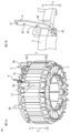
- FIG. 2 is a perspective view showing the configuration of a stator (before molding) of the rotating electric machine according to the first embodiment.
- FIG. 2 is a perspective view showing the configuration of a split core of the stator shown in FIG. 1.
- FIG. FIG. 2 is a perspective view showing the configuration of an insulator on the opposite load side of the stator shown in FIG. 1.
- FIG. FIG. 2 is a perspective view showing the configuration of a load-side insulator of the stator shown in FIG. 1.
- FIG. FIG. 2 is a perspective view showing the configuration of another split core of the stator shown in FIG. 1;
- FIG. 2 is a front view showing the configuration of terminals of the stator shown in FIG. 1.
- FIG. 2 is a front view showing another configuration of the terminals of the stator shown in FIG. 1;
- FIG. 2 is a front view showing another configuration of the terminals of the stator shown in FIG. 1;
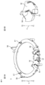
- FIG. 2 is a perspective view showing the configuration of a terminal holder of the stator shown in FIG. 1.
- FIG. 10A is a perspective view of the terminal holder shown in FIG. 9 viewed from the load side, and
- FIG. 10B is an enlarged view showing the configuration of main parts of the terminal holder shown in FIG. 10A.
- 11A is a perspective view of the stator shown in FIG. 1 viewed from the load side, and
- FIG. 11B is an enlarged view showing the configuration of main parts of the stator shown in FIG. 11A.
- FIG. 12A is a cross-sectional perspective view showing a vertical cross section in the axial direction of the stator shown in FIG. 1, and FIG. 12B is an enlarged view showing the configuration of main parts of the stator shown in FIG. 12A.
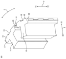
- FIG. 2 is a cross-sectional view showing a longitudinal section in the axial direction showing a partial relationship between the stator shown in FIG. 1 and a mold.
- FIG. 14 is a perspective view showing the structure of a molded stator molded with resin using the mold shown in FIG. 13;
- FIG. 3 is an exploded cross-sectional perspective view showing a longitudinal cross-section in the axial direction showing the structure of another molded stator and housing in the first embodiment.
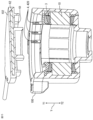
- FIG. 16 is an axial cross-sectional view showing the configuration of a rotating electric machine using the molded stator shown in FIG. 15.
- FIG. FIG. 3 is a perspective view showing the configuration of a stator (before molding) of a rotating electrical machine according to a second embodiment.
- FIG. 2 is an axial cross-sectional view showing the overall relationship between the stator shown in FIG. 1 and a mold.
- FIG. 7 is a perspective view showing a part of the configuration of a terminal holder of a stator of a rotating electric machine according to a third embodiment.
- stator 1 the stator of a rotating electric machine before being molded with a molded resin
- stator 1 the stator 1 after being molded with a molded resin in a mold 8 (see FIG. 13), which will be described later, is referred to as a molded stator 100 (see FIG. 14). It is called.
- FIG. 1 is a perspective view showing the configuration of a stator (before molding) of a rotating electric machine according to a first embodiment.
- FIG. 2 is a perspective view showing the configuration of the split core of the stator shown in FIG. 1.
- FIG. 3 is a perspective view showing the configuration of the anti-load side insulator of the stator shown in FIG. 1.
- FIG. 4 is a perspective view showing the structure of the load-side insulator of the stator shown in FIG. 1.
- FIG. FIG. 5 is a perspective view showing the configuration of another split core of the stator shown in FIG. 1.
- FIG. 6 is a front view showing the configuration of the terminals of the stator shown in FIG. 1.
- FIG. 7 is a front view showing another configuration of the terminals of the stator shown in FIG. 1.
- FIG. 8 is a front view showing another configuration of the terminals of the stator shown in FIG. 1.
- FIG. 9 is a perspective view showing the structure of the terminal holder of the stator shown in FIG. 1.
- FIG. 10A is a perspective view of the terminal holder shown in FIG. 9 as seen from the load side, and
- FIG. 10B is an enlarged view showing the configuration of main parts of the terminal holder shown in FIG. 10A.
- FIG. 11A is a perspective view of the stator shown in FIG. 1 as seen from the load side, and
- FIG. 11B is an enlarged view showing the configuration of main parts of the stator shown in FIG. 11A.
- FIG. 12A is a cross-sectional perspective view showing a vertical cross section in the axial direction of the stator shown in FIG. 1, and FIG. 12B is an enlarged view showing the configuration of the main part of the stator shown in FIG. 12A.
- FIG. 13 is a cross-sectional view showing a longitudinal section in the axial direction showing a part of the relationship between the stator shown in FIG. 1 and a mold.
- FIG. 14 is a perspective view showing the structure of a molded stator molded with resin using the mold shown in FIG. 13.
- FIG. 14 is an exploded cross-sectional view showing the configuration of the molded stator and housing shown in FIG. 13 in an axial longitudinal cross-section.
- FIG. 14 is an axial cross-sectional view showing the configuration of a rotating electric machine using the molded stator shown in FIG. 13.
- FIG. 15 is an exploded cross-sectional perspective view showing the configuration of another molded stator and housing in the first embodiment, showing a vertical cross section in the axial direction.
- FIG. 16 is an axial cross-sectional view showing the configuration of a rotating electric machine using the molded stator shown in FIG. 15.
- FIG. 18 is a cross-sectional view showing the overall relationship between the stator shown in FIG. 1 and a mold in an axial direction.
- the mold 8 used for resin molding will be explained using FIGS. 13 and 18.
- the mold 8 includes a mold positioning portion 81 , a mold recess 82 , a mold contact surface portion 84 having a mold contact surface 83 , and a core rod portion 85 .
- Each part will be explained together with the configuration of the stator 1, which will be described later.
- the stator 1 includes a split coil winding body 11, a terminal 4, and a terminal holder 5.
- the stator 1 is formed by a plurality of split coil winding bodies 11 arranged annularly in the circumferential direction Z.
- the split coil winding body 11 includes a split core 10 , a counter-load side insulator 201 , a load side insulator 202 , and a coil 3 . Note that when both the anti-load side insulator 201 and the load side insulator 202 are referred to, they are referred to as insulator 2.
- the split core 10 includes a yoke portion 12 extending in the circumferential direction Z, that is, extending in an arc shape, and a yoke portion 12 extending in the axial direction Y provided on the outer peripheral surface of the outside X1 in the radial direction X of the yoke portion 12. It includes an extending groove portion 13 and teeth portions 14 that protrude from the yoke portion 12 toward the inner side X2 in the radial direction X, that is, toward the rotation axis Q.
- the split core 10 is made of a magnetic material such as an electromagnetic steel plate.
- the split core 10 includes an anti-load side insulator 201 installed on the anti-load side Y1 in the axial direction Y as shown in FIG.
- a load side insulator 202 installed on the load side Y2 is installed.
- the insulator 2 is made of an insulating material such as resin.
- the insulator 2 includes a winding frame portion 21 that supports the wound coil 3, an inner collar portion 22 that extends in the circumferential direction Z on the inner side X2 of the radial direction X, and rises in the axial direction Y. , and an outer collar portion 23 extending in the circumferential direction Z and rising in the axial direction Y on the outer side X1 in the radial direction X.
- the insulator 2 has a shape that covers part of the yoke portion 12 and the teeth portion 14 of the split core 10, and is fitted and installed on the opposite load side Y1 and the load side Y2 in the axial direction Y of the split core 10.
- the anti-load side insulator 201 includes a hook groove 25 as a first engagement portion for engaging the terminal holder 5 and the anti-load side insulator 201 using a snap-fit mechanism.
- the load-side insulator 202 includes a pressing portion 24 (between the pressing portion 24 and the mold 8) formed to protrude toward the load side Y2 in the axial direction Y to press the mold 8 during mold resin molding. (See FIG. 18).
- the shape of the pressing portion 24 is shown as a cylindrical shape in FIG. 3, it is not limited to this, and may be a polygonal columnar shape as long as it satisfies the same function.
- the coil 3 is formed by winding an electric wire made of a conductive material such as copper or aluminum around the teeth portion 14 of the split core 10 via the anti-load side insulator 201 and the load side insulator 202.
- the method of fixing the plurality of split coil wrapping bodies 11 may be any method as long as it can be fixed annularly in the circumferential direction Z, for example, welding the split coil wrapping bodies 11 adjacent to each other in the circumferential direction Z.
- protrusions 15 and recesses 16 are respectively provided on the side surfaces of the split cores 10 adjacent to each other in the circumferential direction Z, and these protrusions 15 and recesses 16 are fitted together. etc. are possible.
- the stator 1 has three sets of coils 3 continuously wound around four split cores 10, a total of 12 split coil winding bodies 11 in an annular shape. It consists of Since the terminal wires 31 coming out of the coil 3 are two in one set at the beginning and end of winding, there are a total of six terminal wires 31 in the split coil winding body 11.
- the terminal 4 is made of a conductive material such as copper, and has a shape as shown in FIGS. 6 and 7.
- the terminal 4 has a binding portion 41 for binding the terminal wire 31 of the coil 3, a connecting portion 42 for connecting to the outside after molding with resin, and a hook portion 43 for hooking the terminal wire 31.
- the connecting portion 42 has a tab terminal shape.
- other figures of the first embodiment show examples in which the terminal 4 shown in FIG. 7 is used.
- the terminal holder 5 is made of an insulating material such as resin, and has an annular shape as shown in FIGS. 9 and 10, and has an insertion hole 51 into which the connecting portions 42 of the three terminals 4 are inserted, and a contact surface.
- a contact surface portion 52 having a diameter of 520 is provided. As shown in FIG. 13, the contact surface 520 of the contact surface portion 52 contacts the mold contact surface 83 when the connecting portion 42 of the terminal 4 is inserted into the mold recess 82 of the mold contact surface portion 84. They are formed so as to come into contact with each other. Furthermore, the contact surface 520 of the contact surface portion 52 has a shape that covers the connection portion 42 of the terminal 4 .
- the insertion hole 51 is formed with a size that provides a tight fit to the connecting portion 42 of the terminal 4.
- the connecting portion 42 of the terminal 4 is press-fitted and inserted through the contact surface portion 52 of the terminal holder 5 from the load side Y2 in the axial direction Y to the counter-load side Y1.
- the terminal 4 and the insertion hole 51 are installed without a gap, it is possible to prevent resin from passing through the insertion hole 51 and adhering to the connection portion 42 side of the terminal 4 during molding with resin.
- FIG. 10 is a perspective view showing the configuration of the terminal holder 5 viewed from the load side Y2 in the axial direction Y.
- the terminal 4 is on the load side Y2 in the axial direction Y of the abutment surface portion 52.
- a slit 53 matching the shape is created.
- a suppressing portion 54 that suppresses the inclination of the terminal 4 is formed in a part of the slit 53. This prevents the terminal 4 from tilting after the terminal 4 is inserted.
- the terminal holder 5 includes a support portion 55.
- the support portion 55 and the bottom surface 44 of the terminal 4 constitute a second engaging portion that engages the terminal 4 and the terminal holder 5 by a snap-fit mechanism. This is deformed so as to be pushed by the side surface of the terminal 4 when the terminal 4 is inserted, and when the terminal 4 is pushed in until it contacts the terminal holder 5, the support portion 55 enters the bottom surface 44 of the terminal 4.
- the support part 55 can be placed on the bottom surface 44 of the terminal 4 without deteriorating the workability of inserting the terminal 4, and the load side Y2 (downward) in the axial direction Y that is applied when the terminal wire 31 is tied around the terminal 4. It is possible to prevent the terminal 4 from falling off under the load of .
- the outer peripheral portion of the terminal holder 5 is provided with a plurality of first protrusions 56 that come into contact with the mold positioning portion 81 (see FIG. 13) of the mold 8.
- the mold positioning portion 81 is formed by a pin in FIG. 13, the mold positioning portion 81 is not limited to this, and may be formed by a hole.
- the first protrusion 56 has a cylindrical shape in FIG. 9, and specifically shows an example of a cylindrical shape, but is not limited to this, and may have a columnar shape without a hole or a polygonal columnar shape. It's okay.
- FIG. 9 shows an example in which the first protrusions 56 are formed at four locations
- the number is not limited to this, and the number of first protrusions 56 may be two or more as long as the position with respect to the mold 8 can be determined. The number doesn't matter.
- the mold positioning portion 81 provided on the mold 8 side and the first protrusion portion 56 provided on the terminal holder 5 may be formed so as to fit or come into contact with each other.
- the position of the terminal holder 5 during molding with the mold resin is aligned with the mold 8, so the position of the terminal 4 inserted into the terminal holder 5 is also aligned with the mold 8 reference, and the position of the terminal 4 after molding with the mold resin. is no longer influenced by other parts.
- the first protrusion 56 may be omitted.
- the outer peripheral portion of the terminal holder 5 is provided with three fitting portions 58 that fit into the groove portions 13 of the split core 10. Furthermore, as shown in FIGS. 10 and 12, three engaging portions 57 are provided that engage with the hook grooves 25 of the anti-load side insulator 201. As shown in FIG. 12B, the engaging portion 57 is assembled with the hooking groove 25 of the anti-load side insulator 201, and when an external force is applied to the terminal holder 5 in the direction away from the split coil winding body 11, the engaging portion 57 can unintentionally To prevent the holder 5 from coming off. Therefore, the hook groove 25 and the engaging portion 57 form a first engaging portion that engages the terminal holder 5 and the anti-load side insulator 201 with a snap fit mechanism.
- the fitting part 58 is connected to the center of a circle passing through the centers of the four first protrusions 56 of the terminal holder 5, and the center of a circle passing through the centers of the four first protrusions 56 of the terminal holder 5, and the center of the divided coil winding body 11 in which a plurality of pieces are arranged in an annular shape. It is formed for the purpose of aligning with the center of the inner diameter. This is because, as shown in FIG. 13, the mold 8 is formed with a core rod portion 85 that fits into the inner circumference of the split coil winding body 11 of the stator 1, and the stator 1 of FIG.
- the fitting portion 58 is formed in a rectangular prism shape that fits into the groove portion 13 of the split coil winding body 11, as shown in FIG.
- the inner and outer circumferential surfaces and side surfaces of the fitting part 58 are tapered, and the tip of the fitting part 58 has a large taper on either the left or right side to improve the workability of inserting it into the groove part 13.
- the height of the fitting portion 58 in the axial direction Y is such that the insertion into the groove portion 13 of the split coil winding body 11 is started before the fitting portion 57 shown in FIG. 9 contacts the anti-load side insulator 201. Leave it at the height.
- the position of the terminal holder 5 with respect to the split coil winding body 11 is determined first, so that the first engagement part by the snap fit mechanism between the hook groove 25 of the anti-load side insulator 201 and the engagement part 57 of the terminal holder 5 is determined. Workability during formation is improved.
- a second protrusion 512, a third protrusion 59, and a fourth protrusion 510 are provided on the terminal holder 5.
- a pair of second protrusions 512 are provided to hold the neutral point 32 (hereinafter referred to as neutral point 32) of the connection created by twisting the three terminal wires 31.
- the gap between the pair of second protrusions 512 is formed to a size that allows the neutral point 32 to be fitted and held in an intermediate fit.
- the height of the second protrusion 512 in the axial direction Y is formed lower than the height of the first protrusion 56 in the axial direction Y.
- the third protrusion 59 and the fourth protrusion 510 prevent the terminal wire 31 from moving outward in the radial direction This prevents it from floating to the anti-load side Y1.
- the shape of the third protrusion 59 is shown as an example formed in a round column shape in FIG. 1, but it is not limited to this, and may be a polygonal column shape.
- the height of the third protrusion 59 in the axial direction Y is at least twice the wire diameter of the terminal wire 31 and is formed lower than the height of the first protrusion 56 in the axial direction Y. If formed in this way, it is possible to prevent the terminal wire 31 from unintentionally climbing over the third protrusion 59 and moving to the outside X1 in the radial direction X.
- the fourth protrusion 510 has an inverted L-shape as shown in FIG. 9, and includes a wall perpendicular to the axial direction Y.
- the height of the fourth protrusion 510 in the axial direction Y is formed lower than the height of the first protrusion 56 in the axial direction Y.
- the stator of the rotating electrical machine configured as described above and the method of manufacturing the rotating electrical machine will be described.
- a plurality of split coil winding bodies 11 are arranged and fixed in a ring shape.
- the connecting portion 42 of the terminal 4 is press-fitted into the insertion hole 51 of the terminal holder 5 from the load side Y2 in the axial direction Y toward the anti-load side Y1.
- the terminal 4 is held via the slit 53 and the suppressing portion 54.
- the terminal holder 5 and the terminal 4 have a snap-fit mechanism to form a second engaging part in which the bottom surface 44 of the terminal 4 and the support part 55 are engaged, as shown in FIG.
- the fitting part 58 of the terminal holder 5 is inserted and installed into the groove part 13 of the split core 10 of the split coil winding body 11 arranged in an annular manner.
- the terminal holder 5 and the anti-load side insulator 201 have a snap-fit mechanism, and as shown in FIG. 12, the engaging portion 57 is engaged with the hook groove 25 to form a first engaging portion.
- the terminal wire 31 of the coil 3 is wired.
- the terminal wire 31 of the coil 3 is pulled out from the notch 511 of the terminal holder 5.
- Three of the six terminal wires 31 of the coil 3 are wired on the terminal holder 5 to their corresponding terminals 4, and are tied to the binding portions 41 of the terminals 4.
- the terminal wire 31 is hooked on the lower hook portion 43 in the axial direction Y on the paper surface, and the tied portion 41 is The terminal wire 31 is placed on the notch and folded back, and the terminal wire 31 is hooked onto the hook portion 43 near the binding portion 41 and installed. In addition, when using the terminal 4 as shown in FIG. Place it so that it is folded.
- the remaining three terminal wires 31 that cannot be wrapped around the terminal 4 are routed on the terminal holder 5 to the position for creating the neutral point 32, and the three terminal wires 31 are twisted together. Note that when wiring the terminal wire 31, it is routed so as to contact the inner side X2 of the third protrusion 59 on the terminal holder 5 in the radial direction X and the outer side X1 of the fourth protrusion 510 in the radial direction X.
- the neutral point 32 of the connection created by twisting the three terminal wires 31 holds the pair of second protrusions 512 by intermediate fitting. This is to facilitate keeping the neutral point 32 parallel to the axial direction Y and improve soldering workability.
- the terminal wire 31 of the tied portion 41 of the terminal 4 and the neutral point 32 are soldered.
- the stator 1 is put into the mold 8 so that the first cylindrical protrusion 56 of the terminal holder 5 and the corresponding mold positioning part 81 of the mold 8 are aligned. do. Then, the first protrusion 56 is inserted into the mold positioning part 81 and brought into contact with it. At this time, the connecting portion 42 of the terminal 4 is inserted into the mold recess 82 formed in the mold contacting surface portion 84 of the mold 8. The mold contact surface 83 of the mold contact surface portion 84 of the mold 8 and the contact surface 520 of the contact surface portion 52 of the terminal holder 5 are in close contact with each other. In this state, resin molding is performed to form a molded stator 100 as shown in FIG. 14.
- the mold stator 100 is formed by installing the mold 8 on the stator 1, the position of the terminal 4 after molding with resin is influenced by the split coil wrapping 11, the insulator 2, etc. It can be placed without Furthermore, resin adhesion to the connecting portions 42 of the terminals 4 can be prevented without a protective member for the connecting portions 42 of the terminals 4.
- the entire periphery of the connecting portion 42 of the terminal 4 can be sealed, and resin adhesion to the connecting portion 42 of the terminal 4 can be avoided without installing a protective member on the connecting portion 42.
- the terminal 4 uses a bifurcated connecting portion 420 having a bifurcated shape (tuning fork terminal shape) as shown in FIG.
- a molded stator 100 is formed as shown in FIG. 15.
- the tab terminal 61 installed on the board 62 built into the bracket 102 is assembled to the connection part 420 of the terminal 4 of the molded stator 100.
- the tab terminal 61 and the connecting portion 420 of the terminal 4 on the stator 1 side are aligned, and the tab terminal 61 and the connecting portion 420 are fitted and assembled.
- the thickness of the plate should be greater than the gap at the tip of the shape. Then, the rotor 111 that is rotatably arranged and facing the teeth portions 14 of the molded stator 100 with a gap therebetween is assembled, and the bracket 102 is fitted to form the rotating electric machine 110.
- the rotating electric machine 110 is formed in this way, parts such as lead wires can be reduced, which also leads to a reduction in the number of man-hours.
- the tab terminal 61 and the bracket 102 may be formed integrally as shown in FIG. 15, or may be formed separately. Further, an electronic circuit may be provided in addition to the tab terminal 61. If the connecting portion 42 of the terminal 4 of the stator 1 shown above has a tab terminal shape as shown in FIGS. 6 and 7, it may be connected to the tab terminal 61 of the bracket 102 using, for example, a lead wire. .
- a stator for a rotating electrical machine that is molded with resin using a mold, A yoke portion extending in the circumferential direction, a groove portion provided on a radially outer outer circumferential surface of the yoke portion, and a teeth portion protruding radially inward from the radially inner inner circumferential surface of the yoke portion.
- an anti-load side insulator that covers one anti-load side of the split core in the axial direction, a load-side insulator that covers the other load side of the split core in the axial direction, and the anti-load side insulator and the load-side insulator a plurality of split coil winding bodies each having a coil wound around the teeth portion are arranged in an annular shape; a terminal holder installed on the anti-load side of the split coil winding body in the axial direction; a terminal installed in the terminal holder, having a connection part for connecting with the outside, and a terminal to which a terminal wire of the coil is wired;
- the terminal holder is a fitting part that fits into the groove part of the split core; a first protrusion that comes into contact with a mold positioning part of the mold;
- the connecting portion of the terminal is press-fitted from the load side in the axial direction to the anti-load side, and the connecting portion of the terminal is installed so as to protrude toward the anti-load side in the axial
- the position of the terminal during mold resin molding is determined by the first protrusion and the mold positioning part of the mold during mold resin molding, regardless of the stator and insulator, so manufacturing variations in the stator and insulator are not affected. This improves the positioning accuracy of the terminals.
- the first protrusion is formed in a cylindrical shape
- a method for manufacturing a stator of a rotating electric machine as described above A method for manufacturing a stator of a rotating electric machine as described above, The connecting portion of the terminal is press-fitted from the axial load side of the contact surface portion of the terminal holder to the anti-load side, and the connecting portion is installed so as to protrude toward the axial anti-load side; After fitting the fitting part of the terminal holder into the groove part of the split core and wiring the terminal wire of the coil to the terminal, Using the mold having a mold contact surface portion in which the mold positioning portion and the mold recess are formed, Inserting the cylindrical first protrusion of the terminal holder into the mold positioning part of the mold to abut it, The connection portion of the terminal is inserted into the mold recess of the mold, and the contact surface portion of the terminal holder is brought into contact with the mold contact surface portion
- a method for manufacturing a stator of a rotating electric machine as described above The connecting portion of the terminal is press-fitted from the axial load side of the contact surface portion of the terminal holder to the anti-load side, and the connecting portion is installed so as to protrude toward the axial anti-load side; After fitting the fitting part of the terminal holder into the groove part of the split core and wiring the terminal wire of the coil to the terminal, Using the mold having a mold contact surface portion in which the mold positioning portion and the mold recess are formed, bringing the first protrusion of the terminal holder into contact with the mold positioning part of the mold; The connecting portion of the terminal is inserted into the mold recess of the mold, and the contact surface portion of the terminal holder is brought into contact with the mold contact surface portion of the mold to perform mold resin molding.
- the terminal holder and the anti-load side insulator include a first engaging portion that is engaged with each other by a snap fit mechanism, When the anti-load side of the assembled terminal holder in the axial direction is directed downward, it is possible to prevent the terminal holder from falling from the split coil winding body.
- the terminal holder includes a pair of second protrusions that sandwich the neutral point of the connection of the terminal wire of the coil and are lower in height than the first protrusion, Since the neutral point is fitted into the gap between the pair of second protrusions with an intermediate fit, Further, when soldering the neutral point, it is possible to suppress the posture of the neutral point from being tilted with respect to the rotation axis, and the soldering work efficiency is improved.
- the terminal includes a binding portion for tying the terminal wire of the coil and a hook portion for hooking the terminal wire of the coil,
- the movement of the terminal wire when the terminal wire is tied to the terminal can be suppressed, and the workability of binding the terminal wire is improved.
- the movement of the terminal wire during mold resin molding can be suppressed, and the workability of mold resin molding can be improved.
- the terminal holder and the terminal are provided with a second engaging part that is engaged with each other by a snap fit mechanism, It is possible to prevent the terminal from tilting or falling off when the terminal wire is tied to the terminal.
- a third protrusion is provided on the anti-load side of the terminal holder in the axial direction, the third protrusion being higher than twice the wire diameter of the terminal wire of the coil and lower than the first protrusion; Since the terminal wire is brought into contact with the third protrusion and wired to the terminal, The movement of the terminal wire when the terminal wire is tied to the terminal can be suppressed, and the workability of binding the terminal wire is improved. Moreover, the movement of the terminal wire during mold resin molding can be suppressed, and the workability of mold resin molding can be improved.
- a fourth protrusion having an inverted L shape and having a height lower than the first protrusion is provided on the anti-load side of the terminal holder in the axial direction, Since the terminal wire is brought into contact with the fourth protrusion and wired to the terminal, The wired terminal wire can be prevented from floating in the axial direction during mold resin molding, and the workability of mold resin molding can be improved.
- the connecting portion of the terminal is formed in a bifurcated shape, Since the bracket has a tab terminal fixed in a direction perpendicular to the direction of the bifurcated spacing of the connecting portion of the terminal, In the connection between the connecting part of the terminal and the tab terminal of the bracket, the connecting part and the tab terminal can be connected without using other parts such as lead wires, so the number of parts and the number of work steps can be reduced.
- the contact surface of the contact surface portion has a shape that covers the connection portion of the terminal, The positioning accuracy of the mold with the mold positioning section can be further improved.
- Embodiment 2 the shape of the fitting portion 580 of the terminal holder 5 that fits into the groove portion 13 of the split core 10 of the split coil winding body 11 is formed into a bifurcated shape as shown in FIG. .
- the other parts are the same as those in the first embodiment, so the explanation will be omitted as appropriate.
- the shape of the fitting portion 58 of the terminal holder 5 in the first embodiment described above when fitting with the groove portion 13 of the split core 10 of the split coil winding body 11, the circumferential side surface of the fitting portion 58 and the split core 10 are connected. From the point where they make contact, increase the insertion force and push in.
- the fitting portion 580 shown in FIG. 17 into a bifurcated shape, the distance between the two forked portions can be reduced, and the load when inserting the terminal holder 5 can be reduced.
- the fitting portion of the terminal holder is formed in a bifurcated shape, When inserting the fitting part into the groove of the split coil winding body, the fitting part is deformed by the amount of interference with the groove, so that the insertion work efficiency is improved.
- FIG. 19 is a perspective view showing a part of the configuration of a terminal holder of a stator of a rotating electrical machine according to Embodiment 3.
- a fifth protrusion 550 as shown in FIG. 19 is formed at the insertion hole 51 of the terminal holder 5 shown in each of the above embodiments. That is, the terminal holder 5 has a fifth protrusion formed on the anti-load side Y1 of the terminal holder 5 in the axial direction Y, inside the abutting surface 520 of the abutting surface portion 52, and around the connecting portion 42 of the terminal 4. It is equipped with 550. Note that the other parts are the same as those in each of the above embodiments, and therefore the description will be omitted as appropriate.
- the terminals 4 are connected to each other by the water droplets on the contact surface 520, and thereby the terminals 4 may be electrically connected to each other and cause a short circuit.
- the fifth protrusion 550 shown in FIG. 19 of the third embodiment the fifth protrusion 550 prevents the terminals 4 from being connected to each other by water droplets, thereby preventing a short circuit.
- the terminal holder includes a fifth protrusion formed on the opposite load side of the terminal holder in the axial direction, inside the abutting surface of the abutting surface portion and around the connecting portion of the terminal. , When water droplets form on the contact surface of the terminal holder due to condensation, the terminals are prevented from being electrically connected and short-circuited, ensuring the integrity of the product.
Landscapes
- Engineering & Computer Science (AREA)
- Power Engineering (AREA)
- Manufacturing & Machinery (AREA)
- Insulation, Fastening Of Motor, Generator Windings (AREA)
Priority Applications (1)
| Application Number | Priority Date | Filing Date | Title |
|---|---|---|---|
| JP2024507648A JP7770753B2 (ja) | 2022-03-17 | 2023-02-22 | 回転電機のステータ、回転電機、回転電機のステータの製造方法、および、回転電機の製造方法 |
Applications Claiming Priority (2)
| Application Number | Priority Date | Filing Date | Title |
|---|---|---|---|
| JP2022042115 | 2022-03-17 | ||
| JP2022-042115 | 2022-03-17 |
Publications (1)
| Publication Number | Publication Date |
|---|---|
| WO2023176339A1 true WO2023176339A1 (ja) | 2023-09-21 |
Family
ID=88023397
Family Applications (1)
| Application Number | Title | Priority Date | Filing Date |
|---|---|---|---|
| PCT/JP2023/006362 Ceased WO2023176339A1 (ja) | 2022-03-17 | 2023-02-22 | 回転電機のステータ、回転電機、回転電機のステータの製造方法、および、回転電機の製造方法 |
Country Status (2)
| Country | Link |
|---|---|
| JP (1) | JP7770753B2 (https=) |
| WO (1) | WO2023176339A1 (https=) |
Citations (13)
| Publication number | Priority date | Publication date | Assignee | Title |
|---|---|---|---|---|
| JPH06178483A (ja) * | 1992-12-04 | 1994-06-24 | Shibaura Eng Works Co Ltd | モールドモータ |
| JP2013042633A (ja) * | 2011-08-19 | 2013-02-28 | Nippon Densan Corp | モータ |
| WO2013065736A1 (ja) * | 2011-11-04 | 2013-05-10 | 株式会社ミツバ | 電動モータ装置及びその組み立て方法 |
| JP2014100029A (ja) * | 2012-11-15 | 2014-05-29 | Sanyo Denki Co Ltd | 分割コア型モータ、および分割コア型モータの電機子の製造方法 |
| JP2014180191A (ja) * | 2013-02-18 | 2014-09-25 | Nidec Techno Motor Corp | モータ |
| WO2014148537A1 (ja) * | 2013-03-21 | 2014-09-25 | 三菱電機株式会社 | 電動機の固定子、電動機、空気調和機、及び電動機の固定子の製造方法 |
| WO2016194347A1 (ja) * | 2015-06-05 | 2016-12-08 | デンソートリム株式会社 | 内燃機関用回転電機およびそのステータ |
| WO2017115681A1 (ja) * | 2015-12-28 | 2017-07-06 | マブチモーター株式会社 | 電気的接続部の構造,この構造が適用されたロータ及びモータ並びに電気的接続部の形成方法 |
| WO2020026710A1 (ja) * | 2018-08-03 | 2020-02-06 | 日本電産株式会社 | ステータ、およびモータ |
| JP2020054127A (ja) * | 2018-09-27 | 2020-04-02 | 日本電産サンキョー株式会社 | モータ |
| JP2020137288A (ja) * | 2019-02-21 | 2020-08-31 | 三菱電機株式会社 | 回転電機 |
| WO2020195398A1 (ja) * | 2019-03-28 | 2020-10-01 | 日本電産株式会社 | モータ |
| JP2021052492A (ja) * | 2019-09-25 | 2021-04-01 | 日本電産株式会社 | バスバーユニットおよびモータ |
-
2023
- 2023-02-22 JP JP2024507648A patent/JP7770753B2/ja active Active
- 2023-02-22 WO PCT/JP2023/006362 patent/WO2023176339A1/ja not_active Ceased
Patent Citations (13)
| Publication number | Priority date | Publication date | Assignee | Title |
|---|---|---|---|---|
| JPH06178483A (ja) * | 1992-12-04 | 1994-06-24 | Shibaura Eng Works Co Ltd | モールドモータ |
| JP2013042633A (ja) * | 2011-08-19 | 2013-02-28 | Nippon Densan Corp | モータ |
| WO2013065736A1 (ja) * | 2011-11-04 | 2013-05-10 | 株式会社ミツバ | 電動モータ装置及びその組み立て方法 |
| JP2014100029A (ja) * | 2012-11-15 | 2014-05-29 | Sanyo Denki Co Ltd | 分割コア型モータ、および分割コア型モータの電機子の製造方法 |
| JP2014180191A (ja) * | 2013-02-18 | 2014-09-25 | Nidec Techno Motor Corp | モータ |
| WO2014148537A1 (ja) * | 2013-03-21 | 2014-09-25 | 三菱電機株式会社 | 電動機の固定子、電動機、空気調和機、及び電動機の固定子の製造方法 |
| WO2016194347A1 (ja) * | 2015-06-05 | 2016-12-08 | デンソートリム株式会社 | 内燃機関用回転電機およびそのステータ |
| WO2017115681A1 (ja) * | 2015-12-28 | 2017-07-06 | マブチモーター株式会社 | 電気的接続部の構造,この構造が適用されたロータ及びモータ並びに電気的接続部の形成方法 |
| WO2020026710A1 (ja) * | 2018-08-03 | 2020-02-06 | 日本電産株式会社 | ステータ、およびモータ |
| JP2020054127A (ja) * | 2018-09-27 | 2020-04-02 | 日本電産サンキョー株式会社 | モータ |
| JP2020137288A (ja) * | 2019-02-21 | 2020-08-31 | 三菱電機株式会社 | 回転電機 |
| WO2020195398A1 (ja) * | 2019-03-28 | 2020-10-01 | 日本電産株式会社 | モータ |
| JP2021052492A (ja) * | 2019-09-25 | 2021-04-01 | 日本電産株式会社 | バスバーユニットおよびモータ |
Also Published As
| Publication number | Publication date |
|---|---|
| JP7770753B2 (ja) | 2025-11-17 |
| JPWO2023176339A1 (https=) | 2023-09-21 |
Similar Documents
| Publication | Publication Date | Title |
|---|---|---|
| JP5333996B2 (ja) | 固定子およびこれを用いた回転電機 | |
| JP5016969B2 (ja) | 回転電機の配電部品 | |
| US8508088B2 (en) | Wiring component for motor coil | |
| JP5109577B2 (ja) | 回転電機および絶縁部材 | |
| US11323002B2 (en) | Rotary electric machine | |
| EP1641107B1 (en) | Stepping motor and method of manufacturing the same | |
| WO2018150964A1 (ja) | モータおよびポンプ装置 | |
| JP2008278632A (ja) | 分割ステータおよび分割ステータの製造方法 | |
| US8222779B2 (en) | Stepping motor | |
| US20040021375A1 (en) | Stepping motor and manufacturing method therefor | |
| CN111095754A (zh) | 定子构造以及旋转变压器 | |
| JP2019146367A (ja) | ステータ構造およびレゾルバ | |
| US10608483B2 (en) | Stator, electric motor, and air conditioner | |
| JP2002272050A (ja) | レゾルバステータ構造 | |
| CN115668701B (zh) | 定子以及马达 | |
| WO2023176339A1 (ja) | 回転電機のステータ、回転電機、回転電機のステータの製造方法、および、回転電機の製造方法 | |
| JP3544640B2 (ja) | レゾルバ構造 | |
| US20210351657A1 (en) | Motor | |
| JP6684749B2 (ja) | モータ | |
| US12407212B2 (en) | Motor with a motor terminal | |
| JPWO2005124969A1 (ja) | 電動機固定子 | |
| WO2018220936A1 (ja) | モータ | |
| US7414344B2 (en) | Commutator and an armature | |
| JP4247151B2 (ja) | 回転電機 | |
| JP7727376B2 (ja) | モータ |
Legal Events
| Date | Code | Title | Description |
|---|---|---|---|
| 121 | Ep: the epo has been informed by wipo that ep was designated in this application |
Ref document number: 23770298 Country of ref document: EP Kind code of ref document: A1 |
|
| WWE | Wipo information: entry into national phase |
Ref document number: 2024507648 Country of ref document: JP |
|
| NENP | Non-entry into the national phase |
Ref country code: DE |
|
| 122 | Ep: pct application non-entry in european phase |
Ref document number: 23770298 Country of ref document: EP Kind code of ref document: A1 |