WO2023176261A1 - プロペラシャフトの製造方法、及びプロペラシャフト - Google Patents
プロペラシャフトの製造方法、及びプロペラシャフト Download PDFInfo
- Publication number
- WO2023176261A1 WO2023176261A1 PCT/JP2023/005196 JP2023005196W WO2023176261A1 WO 2023176261 A1 WO2023176261 A1 WO 2023176261A1 JP 2023005196 W JP2023005196 W JP 2023005196W WO 2023176261 A1 WO2023176261 A1 WO 2023176261A1
- Authority
- WO
- WIPO (PCT)
- Prior art keywords
- propeller shaft
- open end
- cylindrical
- joint
- diameter
- Prior art date
- Legal status (The legal status is an assumption and is not a legal conclusion. Google has not performed a legal analysis and makes no representation as to the accuracy of the status listed.)
- Ceased
Links
Images





Classifications
-
- B—PERFORMING OPERATIONS; TRANSPORTING
- B21—MECHANICAL METAL-WORKING WITHOUT ESSENTIALLY REMOVING MATERIAL; PUNCHING METAL
- B21K—MAKING FORGED OR PRESSED METAL PRODUCTS, e.g. HORSE-SHOES, RIVETS, BOLTS OR WHEELS
- B21K1/00—Making machine elements
- B21K1/06—Making machine elements axles or shafts
- B21K1/10—Making machine elements axles or shafts of cylindrical form
-
- B—PERFORMING OPERATIONS; TRANSPORTING
- B21—MECHANICAL METAL-WORKING WITHOUT ESSENTIALLY REMOVING MATERIAL; PUNCHING METAL
- B21K—MAKING FORGED OR PRESSED METAL PRODUCTS, e.g. HORSE-SHOES, RIVETS, BOLTS OR WHEELS
- B21K1/00—Making machine elements
- B21K1/06—Making machine elements axles or shafts
-
- B—PERFORMING OPERATIONS; TRANSPORTING
- B23—MACHINE TOOLS; METAL-WORKING NOT OTHERWISE PROVIDED FOR
- B23K—SOLDERING OR UNSOLDERING; WELDING; CLADDING OR PLATING BY SOLDERING OR WELDING; CUTTING BY APPLYING HEAT LOCALLY, e.g. FLAME CUTTING; WORKING BY LASER BEAM
- B23K20/00—Non-electric welding by applying impact or other pressure, with or without the application of heat, e.g. cladding or plating
- B23K20/12—Non-electric welding by applying impact or other pressure, with or without the application of heat, e.g. cladding or plating the heat being generated by friction; Friction welding
- B23K20/129—Non-electric welding by applying impact or other pressure, with or without the application of heat, e.g. cladding or plating the heat being generated by friction; Friction welding specially adapted for particular articles or work
-
- B—PERFORMING OPERATIONS; TRANSPORTING
- B23—MACHINE TOOLS; METAL-WORKING NOT OTHERWISE PROVIDED FOR
- B23K—SOLDERING OR UNSOLDERING; WELDING; CLADDING OR PLATING BY SOLDERING OR WELDING; CUTTING BY APPLYING HEAT LOCALLY, e.g. FLAME CUTTING; WORKING BY LASER BEAM
- B23K26/00—Working by laser beam, e.g. welding, cutting or boring
- B23K26/20—Bonding
- B23K26/21—Bonding by welding
- B23K26/24—Seam welding
- B23K26/28—Seam welding of curved planar seams
- B23K26/282—Seam welding of curved planar seams of tube sections
-
- B—PERFORMING OPERATIONS; TRANSPORTING
- B60—VEHICLES IN GENERAL
- B60K—ARRANGEMENT OR MOUNTING OF PROPULSION UNITS OR OF TRANSMISSIONS IN VEHICLES; ARRANGEMENT OR MOUNTING OF PLURAL DIVERSE PRIME-MOVERS IN VEHICLES; AUXILIARY DRIVES FOR VEHICLES; INSTRUMENTATION OR DASHBOARDS FOR VEHICLES; ARRANGEMENTS IN CONNECTION WITH COOLING, AIR INTAKE, GAS EXHAUST OR FUEL SUPPLY OF PROPULSION UNITS IN VEHICLES
- B60K17/00—Arrangement or mounting of transmissions in vehicles
- B60K17/22—Arrangement or mounting of transmissions in vehicles characterised by arrangement, location, or type of main drive shafting, e.g. cardan shaft
-
- F—MECHANICAL ENGINEERING; LIGHTING; HEATING; WEAPONS; BLASTING
- F16—ENGINEERING ELEMENTS AND UNITS; GENERAL MEASURES FOR PRODUCING AND MAINTAINING EFFECTIVE FUNCTIONING OF MACHINES OR INSTALLATIONS; THERMAL INSULATION IN GENERAL
- F16C—SHAFTS; FLEXIBLE SHAFTS; ELEMENTS OR CRANKSHAFT MECHANISMS; ROTARY BODIES OTHER THAN GEARING ELEMENTS; BEARINGS
- F16C3/00—Shafts; Axles; Cranks; Eccentrics
- F16C3/02—Shafts; Axles
- F16C3/023—Shafts; Axles made of several parts, e.g. by welding
-
- F—MECHANICAL ENGINEERING; LIGHTING; HEATING; WEAPONS; BLASTING
- F16—ENGINEERING ELEMENTS AND UNITS; GENERAL MEASURES FOR PRODUCING AND MAINTAINING EFFECTIVE FUNCTIONING OF MACHINES OR INSTALLATIONS; THERMAL INSULATION IN GENERAL
- F16C—SHAFTS; FLEXIBLE SHAFTS; ELEMENTS OR CRANKSHAFT MECHANISMS; ROTARY BODIES OTHER THAN GEARING ELEMENTS; BEARINGS
- F16C3/00—Shafts; Axles; Cranks; Eccentrics
- F16C3/02—Shafts; Axles
- F16C3/03—Shafts; Axles telescopic
-
- B—PERFORMING OPERATIONS; TRANSPORTING
- B23—MACHINE TOOLS; METAL-WORKING NOT OTHERWISE PROVIDED FOR
- B23K—SOLDERING OR UNSOLDERING; WELDING; CLADDING OR PLATING BY SOLDERING OR WELDING; CUTTING BY APPLYING HEAT LOCALLY, e.g. FLAME CUTTING; WORKING BY LASER BEAM
- B23K20/00—Non-electric welding by applying impact or other pressure, with or without the application of heat, e.g. cladding or plating
- B23K20/12—Non-electric welding by applying impact or other pressure, with or without the application of heat, e.g. cladding or plating the heat being generated by friction; Friction welding
- B23K20/122—Non-electric welding by applying impact or other pressure, with or without the application of heat, e.g. cladding or plating the heat being generated by friction; Friction welding using a non-consumable tool, e.g. friction stir welding
-
- B—PERFORMING OPERATIONS; TRANSPORTING
- B23—MACHINE TOOLS; METAL-WORKING NOT OTHERWISE PROVIDED FOR
- B23K—SOLDERING OR UNSOLDERING; WELDING; CLADDING OR PLATING BY SOLDERING OR WELDING; CUTTING BY APPLYING HEAT LOCALLY, e.g. FLAME CUTTING; WORKING BY LASER BEAM
- B23K2103/00—Materials to be soldered, welded or cut
- B23K2103/08—Non-ferrous metals or alloys
- B23K2103/10—Aluminium or alloys thereof
-
- F—MECHANICAL ENGINEERING; LIGHTING; HEATING; WEAPONS; BLASTING
- F16—ENGINEERING ELEMENTS AND UNITS; GENERAL MEASURES FOR PRODUCING AND MAINTAINING EFFECTIVE FUNCTIONING OF MACHINES OR INSTALLATIONS; THERMAL INSULATION IN GENERAL
- F16C—SHAFTS; FLEXIBLE SHAFTS; ELEMENTS OR CRANKSHAFT MECHANISMS; ROTARY BODIES OTHER THAN GEARING ELEMENTS; BEARINGS
- F16C2226/00—Joining parts; Fastening; Assembling or mounting parts
- F16C2226/30—Material joints
- F16C2226/36—Material joints by welding
-
- F—MECHANICAL ENGINEERING; LIGHTING; HEATING; WEAPONS; BLASTING
- F16—ENGINEERING ELEMENTS AND UNITS; GENERAL MEASURES FOR PRODUCING AND MAINTAINING EFFECTIVE FUNCTIONING OF MACHINES OR INSTALLATIONS; THERMAL INSULATION IN GENERAL
- F16C—SHAFTS; FLEXIBLE SHAFTS; ELEMENTS OR CRANKSHAFT MECHANISMS; ROTARY BODIES OTHER THAN GEARING ELEMENTS; BEARINGS
- F16C2326/00—Articles relating to transporting
- F16C2326/01—Parts of vehicles in general
- F16C2326/06—Drive shafts
Definitions
- the present invention relates to a method for manufacturing a propeller shaft and a propeller shaft.
- Patent Document 1 As a conventional method for manufacturing a propeller shaft, for example, the method described in Patent Document 1 below is known.
- the method for manufacturing a propeller shaft described in this patent document includes a first step of forming a first cylindrical member in which a first cylindrical portion and a first joint portion are seamlessly integrally formed; A second step of forming a second cylindrical member in which the second cylindrical portion and the second joint portion are seamlessly integrally formed, and a third step of joining the first cylindrical member and the second cylindrical member by friction stir welding. It has a process.
- the first cylindrical member and the second cylindrical member are joined by friction stir welding. Therefore, the thickness of the welded portion of the first cylindrical member and the second cylindrical member is thicker than the end of the first cylindrical member on the first joint part side and the end of the second cylindrical member on the second joint part side. Formed thickly. As a result, the weight of the welded portion between the first cylindrical member and the second cylindrical member increases, and when the propeller shaft rotates, the deflection of the welded portion increases and the rotation of the propeller shaft becomes unbalanced. However, there was still room for improvement in that there was a risk of this happening.
- the present invention was devised in view of the technical problems of the conventional propeller shaft manufacturing method, and it is possible to reduce the thickness of the welded portion between the first cylindrical member and the second cylindrical member.
- the present invention aims to provide a method for manufacturing a propeller shaft and a propeller shaft.
- the thickness of the welded portion between the first cylindrical member and the second cylindrical member is thinner than the thickness of the end (first end) of the first cylindrical member on the first joint portion side. , and is formed thinner than the thickness of the end (first end) of the second cylindrical member on the second joint portion side.
- the thickness of the joint between the first cylindrical member and the second cylindrical member can be reduced.
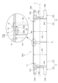
- FIG. 2 is a half-sectional view taken along the axial direction of the propeller shaft according to the first embodiment of the present invention.
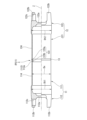
- FIG. 2 is a half-sectional view of the cylindrical member shown in FIG. 1.
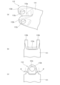
- FIG. FIG. 2 is an enlarged view of the first joint shown in FIG. 1, in which (a) is a perspective view, (b) is a view in the direction of arrow A in (a), and (c) is in the direction of arrow B in (a); It is an arrow view.
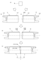
- It is a figure showing the manufacturing method of the propeller shaft concerning a 1st embodiment of the present invention.
- It is a half sectional view taken along the axial direction of the cylindrical member according to the first modification of the first embodiment of the present invention.
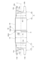
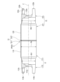
- FIG. 7 is a half-sectional view showing a second embodiment of the present invention, in which a cylindrical member of a propeller shaft according to the second embodiment is cut along the axial direction.
- FIG. 7 is a half-sectional view taken along the axial direction of a cylindrical member according to a first modification of the second embodiment of the present invention. It is a half sectional view taken along the axial direction of a cylindrical member according to a second modification of the second embodiment of the present invention.
- FIG. 7 is a half-sectional view of a cylindrical member of a propeller shaft according to a third embodiment of the present invention, cut along the axial direction.
- FIG. 7 is a half-sectional view taken along the axial direction of a cylindrical member according to a first modification of the third embodiment of the present invention. It is a half sectional view taken along the axial direction of a cylindrical member according to a second modified example of the third embodiment of the present invention.
- propeller shaft will be described by exemplifying a case where the propeller shaft is applied to a propeller shaft for an automobile, as in the conventional case.
- FIG. 1 shows a half-sectional view of the propeller shaft PS1 cut along the axial direction, showing the overall form of the propeller shaft PS1 according to the first embodiment of the present invention.
- the propeller shaft PS1 includes a first rotating shaft (not shown) that is a rotating shaft located at the front of the vehicle, and a second rotating shaft (not shown) that is located at the rear of the vehicle. It is arranged along the front-rear direction of the vehicle between.
- the first rotating shaft is the output shaft of a transmission that is located at the front of the vehicle and to which rotational force is transmitted from a drive source such as an engine or a motor.
- the second rotating shaft corresponds to an input shaft of a differential that is arranged at the rear of the vehicle and transmits rotational force to the rear wheels of the vehicle.
- the propeller shaft PS1 is composed of a generally cylindrical shaft body 1 corresponding to the cylindrical member of the present invention.
- This shaft body 1 is connected to a transmission (not shown) via a first joint member J1, and to a differential (not shown) via a second joint member J2. Further, the shaft body 1 is configured to be divided into two parts in the axial direction, and a first cylindrical member 11 constituting the front half and a second cylindrical member 12 constituting the rear half are connected via a welded portion 13. , is integrally formed.
- the first joint member J1 includes a first drive-side joint member J11 that is integrally rotatably connected to the output shaft of the transmission (not shown) via a spline (not shown), and a front end of the first cylindrical member 11 of the shaft body 1.
- a first cross that is integrally provided in the section and connects a first joint part 112, which will be described later, constituting the first driven joint member J12, and the first drive joint member J11 and the first joint part 112 so as to be integrally rotatable.
- a shaft J13 is provided.
- a generally cylindrical dust cover DC is attached to the outer peripheral side of the base end of the first drive-side joint member J11 so as to overlap in the radial direction with the case of the transmission (not shown). This prevents foreign matter from entering from the outside.
- the second joint member J2 is integrally provided with the second cylindrical member 12 of the shaft main body 1, and is connected to a second joint part 122 (described later) constituting the second driven side joint member J21 and the input shaft of the differential (not shown).
- a second driven side joint member J22 is connected to the second driven side joint member J22 so as to be integrally rotatable via a fastening member (for example, a screw) not shown, and a second driven side joint member J22 is connected so as to be integrally rotatable with the second joint part 122 and the second driven side joint member J22. 2 cross shaft J23.
- the shaft body 1 includes a first cylindrical member 11 constituting a front half, a second cylindrical member 12 constituting a rear half, and a rear end of the first cylindrical member 11 and a second cylindrical member. 12, and a welded portion 13 formed by welding the front end portion of 12 along the circumferential direction, and these are integrally formed.
- the first cylindrical member 11 includes a first cylindrical part 111 formed in a cylindrical shape, and a first joint part 112 formed at the front end of the first cylindrical part 111 and used for connection with the first drive side joint member J11. These are integrally formed.
- the first cylindrical member 11 is formed by plastically deforming a metal material (for example, aluminum), and in this embodiment, it is formed by well-known impact extrusion among cold forging, which is one form of plastic deformation. has been done.
- the first cylindrical portion 111 has a cylindrical shape having a generally constant outer diameter in the axial direction, and a first end portion where the first joint portion 112 is provided is closed by the first joint portion 112. A second end on the opposite side in the axial direction is a first open end 113 that opens to the outside. Further, the first cylindrical portion 111 is formed such that the thickness T1 of the first end portion becomes gradually thicker toward the first joint portion 112 side, and the thickness T2 of the second end portion is formed such that the thickness T1 of the first end portion becomes gradually thicker toward the first joint portion 112 side. It is formed to have a substantially constant thickness, which is thinner than the thickness T1 of the section.
- the first joint part 112 includes a first joint base 112a that closes the first end of the first cylindrical part 111, and a first joint base 112a that extends in the axial direction from the outer surface of the first joint base 112a. It has bifurcated first joint yoke portions 112b, 112b extending generally parallel to the rotational axis Z and facing each other across the rotational axis Z, which are integrally formed.
- the first joint base 112a has a central portion located between the pair of first joint yoke parts 112b, 112b on the axially outer side (the extension of the first joint yoke parts 112b, 112b) than the outer peripheral edge of the first joint base 112a.
- the first joint yoke portions 112b, 112b are extended along the radial direction so as to connect the first joint yoke portions 112b, 112b.
- first joint yoke portions 112b, 112b have side surfaces that are generally parallel to the inside and outside, and are each arranged slightly offset inward from the outer peripheral edge of the first joint base 112a.
- a pair of first joint bearing holes 112c, 112c for bearing the first cross shaft J13 are formed through the first joint yoke parts 112b, 112b so as to face each other with the rotation axis Z interposed therebetween.
- the first joint bearing holes 112c, 112c rotatably support the pair of shaft portions J131, J131 of the first cross shaft J13 via needle bearings NB, respectively.
- first joint yoke parts 112b, 112b are formed so that the outer diameter Dc1 of the first joint yoke parts 112b, 112b is approximately equal to the outer diameter Dt1 of the first cylindrical part 111.
- the outer diameter Dc1 of the first joint yoke parts 112b, 112b only needs to be equal to or smaller than the outer diameter Dt1 of the first cylindrical part 111, and can be arbitrarily set according to the specifications of the first joint member J1. .
- first joint yoke portions 112b, 112b have a relatively large draft angle ⁇ d, and are formed so that the curvature of the corner radius portions 112d, 112d on both sides of the root portion is as large as possible.
- the flow of the metal material (aluminum in this embodiment) during forging (impact extrusion) is relatively good, and the forging of the first joint yoke portions 112b, 112b is relatively easy. There is.
- the second cylindrical member 12 includes a cylindrical second cylindrical portion 121 and a rear end portion of the second cylindrical portion 121, and is connected to the second driven joint member J21.
- a second joint portion 122 is provided, and these are integrally formed.
- the second cylindrical member 12 is formed by plastically deforming a metal material (for example, aluminum). Among forging, it is formed by the well-known impact extrusion.
- the second cylindrical portion 121 has a cylindrical shape having a generally constant outer diameter in the axial direction, and a first end portion where the second joint portion 122 is provided is closed by the second joint portion 122, and the first end portion is closed by the second joint portion 122.
- the second end on the opposite side in the axial direction is a second open end 123 that opens to the outside.
- the second cylindrical portion 121 is formed such that the thickness T1 of the first end portion becomes gradually thicker toward the second joint portion 122 side, and the thickness T2 of the second end portion is It is formed to have a substantially constant thickness, which is thinner than the thickness T1 of the section.
- the second open end portion 123 is configured such that the outer diameter Do2 of the second end portion of the second tube portion 121 is equal to the inner diameter Di1 of the second end portion of the first tube portion 111.
- the second end portion 121 is reduced in diameter in a step-like manner, and is configured to be able to fit inside the first open end portion 113 .
- the second open end portion 123 includes an inner step portion 123a that bends radially inward in a stepped shape, and a reduced diameter portion 123b that reduces in diameter through the inner step portion 123a and extends in the axial direction. , has.
- the second open end portion 123 is in a state in which the inner step portion 123a faces the first open end portion 113 in the axial direction, and the reduced diameter portion 123b is fitted to the inner peripheral side of the first open end portion 113. It is connected to the first open end 113 at.
- the first open end 113 constitutes an encircling portion 113a that covers the outer peripheral side of the reduced diameter portion 123b of the second open end 123.
- the second cylindrical member 12 has the same shape as the first cylindrical member 11 except for the second open end 123.
- the second cylindrical member 12 has an inner stepped portion 123a and a reduced diameter portion 123b added to the first open end portion 113 of the first cylindrical member 11.
- the welded portion 13 is formed by laser welding the first open end 113 of the first cylindrical member 11 and the second open end 123 of the second cylindrical member 21.
- the welded portion 13 is formed over the entire circumference in the circumferential direction, spanning the first open end portion 113 of the first cylindrical portion 111 and the inner step portion 123a of the second cylindrical portion 121. That is, this welded portion 13 is formed between the first open end portion 113 of the first cylindrical portion 111 and the inner step portion 123a of the second cylindrical portion 121 so as to bulge out in a build-up shape.
- the welded portion 13 has a substantially arcuate cross section that expands outward in the radial direction, and has a diameter Dt1 of the first cylindrical portion 111, a diameter Dc1 of the first joint portion 112, a diameter Dt2 of the second cylindrical portion 121, and It has a diameter Dw larger than the diameter Dc2 of the second joint portion 122. Furthermore, the thickness Tw of the welded portion 13 is formed to be thinner than the thickness T1 of the first end of the first cylindrical portion 111 and thinner than the thickness T1 of the first end of the second cylindrical portion 121. .
- an aluminum material M shown in FIG. 4(a) is set in a mold (not shown), and as shown in FIG. 4(b), a first The first cylindrical part 111 and the first joint part 112 are simultaneously molded by pushing the joint part 112 forward and stretching the first cylindrical part 111 backward, thereby forming the first cylindrical member 11. (the first step).
- the aluminum material M shown in FIG. 4(a) is set in a mold (not shown), and as shown in FIG. 4(c), the first joint part 112 is pushed forward by the impact extrusion method.
- the second cylindrical portion 121 and the second joint portion 122 are simultaneously molded to form the second cylindrical member 12 (second step according to the present invention).
- the second cylindrical member 12 is moved until the inner step 123a of the second open end 123 of the second cylindrical member 12 comes into contact with the edge of the first open end 113.
- the reduced diameter portion 123b of the second open end 123 is press-fitted into the inner circumferential side of the first open end 113 of the first cylindrical member 11.
- the first open end 113 of the first cylindrical member 11 and the inner step 123a of the second cylindrical member 12 are welded by laser welding (in accordance with the present invention).
- Third step by forming the welded portion 13 between the first open end 113 of the first cylindrical member 11 and the inner step 123a of the second cylindrical member 12, the manufacture of the shaft body 1 is completed. .
- the first cylindrical member and the second cylindrical member are joined by friction stir welding. Therefore, the thickness of the welded portion of the first cylindrical member and the second cylindrical member is thicker than the end of the first cylindrical member on the first joint part side and the end of the second cylindrical member on the second joint part side. Formed thickly.
- welding is performed by pressing a tool against the abutted ends of the first cylindrical member and the second cylindrical member, which are the joint portion, from the outer periphery side.
- one of the first and second cylindrical members is formed to be thicker than the other, and then overlapped with the inner circumferential side of the other. has been adopted (see FIG. 1 of Patent Document 1).
- the weight of the welded portion between the first cylindrical member and the second cylindrical member increases, and as a result, the deflection of the welded portion increases when the propeller shaft rotates, and the rotation of the propeller shaft becomes unstable. There was still room for improvement in that there was a risk of unbalance.
- the propeller shaft PS1 and the method for manufacturing the propeller shaft PS1 according to the present embodiment have the following effects, thereby solving the technical problems of the conventional method for manufacturing the propeller shaft. I can do it.
- the thickness T1 of the first end of the first cylindrical part 111 is welded to a second open end 123 formed at a second end opposite to the first end of the part 121. and a third step of forming a welded portion 13 that is thinner than the thickness T1 of the first end portion of the second cylindrical portion 121.
- the thickness Tw of the welded part 13 formed by welding the first cylindrical member 11 and the second cylindrical member 12 is equal to the thickness of the first end of the first cylindrical part 111. T1, and thinner than the thickness T1 of the first end of the second cylindrical portion 121. Therefore, the thickness Tw of the welded portion 13 is reduced, and the weight of the welded portion 13 can be reduced. Thereby, it is possible to suppress vibration of the welded portion 13 and unbalance of rotation when the propeller shaft PS1 rotates.
- the plastic working in the first step and the second step is performed by impact extrusion.
- the first cylindrical member 11 and the second cylindrical member 12 are formed by the impact extrusion method, so that the first cylindrical part 111, the first joint part 112, the second cylindrical part 121 and the second joint portion 122 can be formed in the same process.
- the number of man-hours (processes) for forming the first cylindrical member 11 and the second cylindrical member 12 can be reduced, and the equipment for forming the first cylindrical member 11 and the second cylindrical member 12 can be reduced. This makes it possible to reduce the manufacturing cost of the propeller shaft PS1.
- the impact extrusion method it is not necessary to form the first open end portion 113 and the second open end portion 123 thickly, so that the thickness of the first cylindrical portion 111 and the second cylindrical portion 121 can be increased. Since it can be formed thinly, it can also contribute to reducing the weight of the propeller shaft PS1.
- the first joint portion 112 and the second joint portion 122 are formed in a bifurcated yoke shape.
- the first joint part 112 and the second joint part 122 are formed in a bifurcated yoke shape, thereby improving the versatility of the first joint part 112 and the second joint part 122.
- the propeller shaft PS1 can be applied to a vehicle such as a truck, for example, where maintenance of the first joint part 112 and the second joint part 122 is required due to aging deterioration or the like.
- the bifurcated yoke (the first joint yoke portions 112b, 112b) in the first joint portion 112 and the bifurcated yoke (the second The joint yoke portions 122b, 122b) are in phase with each other in the rotational direction.
- the phases in the rotational direction of the first joint yoke parts 112b, 112b of the first joint part 112 and the second joint yoke parts 122b, 122b of the second joint part 122 match each other. By doing so, it becomes possible to cancel rotational fluctuations between the first joint part 112 and the second joint part 122. This contributes to improving the rotational balance of the propeller shaft PS1.
- the welded portion 13 is formed by laser welding.
- the welded part 13 is formed by laser welding, it is possible to minimize the range in which the welded part 13 is affected by heat on the shaft body 1, and the strength generated by welding can be reduced to a minimum. The decrease can be suppressed more effectively.
- the diameter-reducing portion 123b is fitted into the inner peripheral side of the first open end portion 113. Laser welding is performed.
- the second cylindrical portion 121 has a step between the welded portion 13 and the second open end 123 from the welded portion 13 toward the second open end 123.
- the first cylindrical part 111 has a reduced diameter part 123b that reduces in diameter in a shape, and the first cylindrical part 111 has an enveloping part 113a between the first joint part 112 and the first open end part 113, which covers the outer peripheral side of the reduced diameter part 123b.
- the laser beam is emitted while the reduced diameter portion 123b of the second cylindrical member 12 is fitted into the inner peripheral side of the first open end portion 113 (enveloping portion 113a) of the first cylindrical member 11.
- the cylindrical member (shaft main body 1) is formed of a metal material containing aluminum.
- the shaft body 1 is formed of a metal material containing aluminum, the propeller It is possible to reduce the weight of the shaft PS1.
- FIG. 5 shows a first modification of the first embodiment of the propeller shaft according to the present invention, in which the configuration of the shaft body 1 according to the first embodiment is changed.
- the same reference numerals are given to the same configurations as those of the first embodiment, and the explanation thereof will be omitted.
- FIG. 5 shows a propeller shaft PS11 according to a first modification of the first embodiment of the present invention, and shows a half-sectional view of the shaft body 1 cut along the axial direction.
- the propeller shaft PS11 As shown in FIG. 5, the propeller shaft PS11 according to this modification is formed such that the diameter of the axially intermediate portion of the shaft body 1 is reduced, and the outer diameter Dx of the axially intermediate portion of the shaft body 1 is It is formed to be smaller than the outer diameters Dt1 and Dt2 of both axial ends of the shaft body 1 (first ends of the first cylindrical part 111 and the second cylindrical part 121).
- the propeller shaft PS11 is the same as the first embodiment except that the diameter of the axially intermediate portion of the shaft body 1 is reduced.
- the propeller shaft PS11 is provided between the first joint part 112 and the first open end part 113 in the first cylindrical member 11, from the first joint part 112 to the first open end part 113.
- a first reduced diameter portion 114 is formed by reducing the outer diameter in a stepped manner.
- the propeller shaft PS11 is located between the second joint part 122 and the second open end part 123 in the second cylindrical member 12, and extends outward from the second joint part 122 toward the second open end part 123.
- a second reduced diameter portion 124 is formed by reducing the diameter in a stepped manner.
- the second open end portion 123 of the second reduced diameter portion 124 is formed with an inner step portion 123a and a reduced diameter portion 123b whose diameter is further reduced in a stepped manner radially inward.
- the reduced diameter portion 123b provided at the second open end portion 123 of the second reduced diameter portion 124 is connected to the first open end portion 113 of the first reduced diameter portion 114. is formed by laser welding along the circumferential direction between the edge of the first open end 113 and the inner step 123a of the second open end 123 while press-fitted to the inner circumferential side of the second open end 123. ing.
- the first joint part 112 and the first open end part 113 of the first cylindrical member 11 are A first reduced diameter part 114 whose outer diameter decreases from 112 toward the first open end 113 is formed, and in the second step, the second joint part 122 and the second open end 123 in the second cylindrical member 12 are formed.
- a second reduced diameter portion 124 whose outer diameter decreases from the second joint portion 122 toward the second open end portion 123 is formed between the first reduced diameter portion 114 and the second reduced diameter portion 124 in the third step.
- the diameter portion 124 is welded.
- the first cylindrical portion 111 is connected between the first joint portion 112 and the first open end portion 113, and from the first joint portion 112 to the first open end portion 113.
- the second cylindrical portion 121 has a first diameter-reduced portion 114 whose outer diameter decreases toward the end, and the second cylindrical portion 121 has a second open end portion 114 between the second joint portion 122 and the second open end portion 123.
- the welded portion 13 has a second reduced diameter portion 124 whose outer diameter decreases toward the end portion 123, and the first reduced diameter portion 114 and the second reduced diameter portion 124 are welded together.
- the axially intermediate portion of the shaft body 1 is formed in a diameter-reduced shape by the first diameter-reduced portion 114 and the second diameter-reduced portion 124, so that the shaft body 1 is It is possible to suppress an increase in weight, and the weight of the propeller shaft PS11 can be reduced.
- the axially intermediate portion of the shaft body 1 is formed to have a reduced diameter by the first reduced diameter portion 114 and the second reduced diameter portion 124, it can be laid out even in a vehicle with a narrow mounting space. This has the advantage of improving the layout of the propeller shaft PS11.
- FIG. 6 shows a second modification of the first embodiment of the propeller shaft according to the present invention, in which the configuration of the shaft body 1 according to the first embodiment is changed.
- the same reference numerals are given to the same configurations as those of the first embodiment, and the explanation thereof will be omitted.
- FIG. 6 shows a propeller shaft PS12 according to a second modification of the first embodiment of the present invention, and shows a half-sectional view of the shaft body 1 cut along the axial direction.
- the propeller shaft PS12 is formed such that the diameter of the axially intermediate portion of the shaft body 1 increases, and the outer diameter Dx of the axially intermediate portion of the shaft body 1 is It is formed to be larger than the outer diameters Dt1 and Dt2 of both axial ends of the shaft body 1 (first ends of the first cylindrical part 111 and the second cylindrical part 121).
- this propeller shaft PS12 is similar to the first embodiment except that the diameter of the shaft body 1 is enlarged in the axially intermediate portion.
- the propeller shaft PS12 is provided between the first joint part 112 and the first open end part 113 in the first cylinder member 11, and from the first joint part 112 to the first open end part 113.
- a first enlarged diameter portion 115 is formed by enlarging the outer diameter in a stepped manner.
- the propeller shaft PS12 is located between the second joint part 122 and the second open end part 123 in the second cylindrical member 12, and extends outward from the second joint part 122 toward the second open end part.
- a second enlarged diameter portion 125 is formed by enlarging the diameter in a stepped manner.
- the second open end portion 123 of the second enlarged diameter portion 125 is formed with an inner step portion 123a and a reduced diameter portion 123b whose diameter decreases radially inward in a stepped manner.
- the reduced diameter part 123b provided at the second open end 123 of the second enlarged diameter part 125 is connected to the first open end 113 of the first enlarged diameter part 115. is formed by laser welding along the circumferential direction between the edge of the first open end 113 and the inner step 123a of the second open end 123 while press-fitted to the inner circumferential side of the second open end 123. ing.
- the first joint part 112 and the first open end part 113 of the first cylindrical member 11 are A first enlarged diameter portion 115 whose outer diameter increases from 112 toward the first open end 113 is formed, and in the second step, the second joint portion 122 and the second open end 123 of the second cylindrical member 12 are formed.
- a second enlarged diameter part 125 whose outer diameter increases from the second joint part 122 toward the second open end 123 is formed, and in the third step, the first enlarged diameter part 115 and the second enlarged diameter part 125 are formed.
- the diameter portion 125 is welded.
- the first cylindrical portion 111 is connected between the first joint portion 112 and the first open end portion 113 and from the first joint portion 112 to the first open end portion 113.
- the second cylindrical portion 121 has a first enlarged diameter portion 115 whose outer diameter increases toward the outer diameter, and the second cylindrical portion 121 is arranged between the second joint portion 122 and the second open end 123 from the second joint portion 122 to the second open end.
- the welded portion 13 has a second enlarged diameter portion 125 whose outer diameter increases toward the portion 123, and the first enlarged diameter portion 115 and the second enlarged diameter portion 125 are welded together.
- the axially intermediate portion of the shaft body 1 is formed to have an expanded diameter by the first expanded diameter portion 115 and the second expanded diameter portion 125, so that the propeller shaft PS12 can be Strength can be improved.
- the axially intermediate portion of the shaft body 1 is formed to have an enlarged diameter by the first enlarged diameter portion 115 and the second enlarged diameter portion 125, the bending characteristic value of the propeller shaft PS12 can be improved.
- FIG. 7 shows a second embodiment of a propeller shaft according to the present invention, in which the configuration of the welded portion 13 according to the first embodiment is changed.
- the same reference numerals are given to the same configurations as those of the first embodiment, and the explanation thereof will be omitted.
- FIG. 7 shows a half-sectional view of the shaft body 1 of the propeller shaft PS2 according to the second embodiment of the present invention, taken along the axial direction.
- the propeller shaft PS2 includes a first cylindrical member 11 and a second cylindrical member 12, as in the first embodiment, and a first joint of a first joint portion 112.
- the first open end portion 113 and the second open end portion 123 are formed by laser welding such that the rotational phase of the yoke portions 112b, 112b matches the rotational phase of the second joint yoke portions 122b, 122b. They are joined via a welded portion 13.
- the inner diameter Di2 of the second end of the second cylindrical portion 121 is the outer diameter Do1 of the second end of the first cylindrical portion 111.
- the second end portion of the second cylindrical portion 121 is enlarged in diameter in a step-like manner so as to be equivalent to the first open end portion 113 .
- the second open end portion 123 of the second cylindrical portion 121 has an outer step portion 123c that bends radially outward in a stepped shape, and expands in diameter through the outer step portion 123c and extends along the axial direction. It has an enlarged diameter portion 123d.
- the second open end portion 123 is in a state in which the outer stepped portion 123c faces the first open end portion 113 in the axial direction, and the enlarged diameter portion 123d is fitted to the outer peripheral side of the first open end portion 113. and is connected to the first open end 113.
- the first open end 113 constitutes an enclosed portion 113b that is covered by the inner peripheral side of the enlarged diameter portion 123d of the second open end 123.
- the second cylindrical member 12 has the same shape as the first cylindrical member 11 except for the second open end 123.
- the second cylindrical member 12 has an outer stepped portion 123c and an enlarged diameter portion 123d added to the first open end portion 113 of the first cylindrical member 11.
- the welded portion 13 is formed over the entire circumference along the circumferential direction so as to straddle the first open end 113 of the first cylindrical portion 111 and the outer step portion 123c of the second cylindrical portion 121. That is, this welded portion 13 is formed between the first open end portion 113 of the first cylindrical portion 111 and the outer step portion 123c of the second cylindrical portion 121 so as to bulge out in a build-up shape.
- the welded portion 13 has a substantially arcuate cross section that expands outward in the radial direction, and has a diameter Dt1 of the first cylindrical portion 111, a diameter Dc1 of the first joint portion 112, a diameter Dt2 of the second cylindrical portion 121, and It has a diameter Dw larger than the diameter Dc2 of the second joint portion 122. Furthermore, the thickness Tw of the welded portion 13 is formed to be thinner than the thickness T1 of the first end of the first cylindrical portion 111 and thinner than the thickness T1 of the first end of the second cylindrical portion 121. There is.
- a second joint is formed between the second joint part 122 and the second open end part 123 of the second cylindrical member 12.
- An enlarged diameter portion 123d is formed that increases in diameter from the portion 122 toward the second open end portion 123 in a stepped manner, and in the third step, the enlarged diameter portion 123d extends from the first open end portion 113 (enclosed portion 113b). Laser welding is performed with the parts fitted on the outer circumferential side.
- the second cylindrical portion 121 is connected between the welded portion 13 and the second open end portion 123 from the second joint portion 122 to the second open end portion 123.
- the first cylindrical portion 111 has an enlarged diameter portion 123d that expands in diameter in a stepped manner, and the first cylindrical portion 111 has a cover on the inner peripheral side of the enlarged diameter portion 123d between the first joint portion 112 and the first open end 113. It has an enclosed portion 113b.
- the laser beam is emitted while the enlarged diameter portion 123d of the second cylindrical member 12 is fitted to the outer circumferential side of the first open end portion 113 (enclosed portion 113b) of the first cylindrical member 11.
- the laser beam is emitted while the enlarged diameter portion 123d of the second cylindrical member 12 is fitted to the outer circumferential side of the first open end portion 113 (enclosed portion 113b) of the first cylindrical member 11.
- FIG. 8 shows a first modification of the second embodiment of the propeller shaft according to the present invention, in which the configuration of the shaft body 1 according to the second embodiment is changed.
- the same components as the second embodiment are given the same reference numerals, and the explanation thereof will be omitted.
- FIG. 8 shows a propeller shaft PS21 according to a first modification of the second embodiment of the present invention, and shows a half-sectional view of the shaft body 1 cut along the axial direction.
- the propeller shaft PS21 is formed such that the axially intermediate portion of the shaft body 1 is reduced in diameter, and the outer diameter Dx of the axially intermediate portion of the shaft body 1 is It is formed to be smaller than the outer diameters Dt1 and Dt2 of both axial ends of the shaft body 1 (first ends of the first cylindrical part 111 and the second cylindrical part 121).
- this propeller shaft PS21 is the same as the second embodiment except that the diameter of the axially intermediate portion of the shaft body 1 is reduced.
- the propeller shaft PS21 is provided between the first joint part 112 and the first open end part 113 in the first cylindrical member 11, from the first joint part 112 to the first open end part 113.
- a first reduced diameter portion 114 is formed by reducing the outer diameter in a stepped manner.
- the propeller shaft PS21 is located between the second joint part 122 and the second open end part 123 in the second cylindrical member 12, and extends outward from the second joint part 122 toward the second open end part 123.
- a second reduced diameter portion 124 is formed by reducing the diameter in a stepped manner.
- the second open end 123 of the second reduced-diameter portion 124 is formed with an outer step portion 123c and an enlarged-diameter portion 123d whose diameter increases radially outward in a stepped manner.
- the enlarged diameter portion 123d provided at the second open end portion 123 of the second reduced diameter portion 124 is connected to the first open end portion 113 of the first reduced diameter portion 114. While press-fitted to the outer circumferential side, laser welding is performed along the circumferential direction between the tip edge of the enlarged diameter portion 123d of the second open end 123 and the outer circumferential surface of the first open end 113. It is formed.
- the axially intermediate portion of the shaft body 1 is formed in a diameter-reduced shape by the first diameter-reduced portion 114 and the second diameter-reduced portion 124, so that the shaft body 1 It is possible to suppress an increase in weight, and the weight of the propeller shaft PS21 can be reduced.
- the axially intermediate portion of the shaft body 1 is formed in a reduced diameter shape by the first reduced diameter portion 114 and the second reduced diameter portion 124, it is suitable for vehicles with narrow mounting space. This has the advantage of improving the layout of the propeller shaft PS21.
- FIG. 9 shows a second modification of the second embodiment of the propeller shaft according to the present invention, in which the configuration of the shaft body 1 according to the second embodiment is changed.
- the same components as the second embodiment are given the same reference numerals, and the explanation thereof will be omitted.
- FIG. 9 shows a propeller shaft PS22 according to a second modification of the second embodiment of the present invention, and shows a half-sectional view of the shaft body 1 cut along the axial direction.
- the propeller shaft PS22 is formed such that the axially intermediate portion of the shaft body 1 is expanded in diameter, and the outer diameter Dx of the axially intermediate portion of the shaft body 1 is It is formed to be larger than the outer diameters Dt1 and Dt2 of both axial ends of the shaft body 1 (first ends of the first cylindrical part 111 and the second cylindrical part 121).
- this propeller shaft PS22 is the same as the second embodiment except that the diameter of the axially intermediate portion of the shaft body 1 is enlarged.
- the propeller shaft PS22 is provided between the first joint part 112 and the first open end part 113 in the first cylindrical member 11, from the first joint part 112 to the first open end part 113.
- a first enlarged diameter portion 115 is formed by enlarging the outer diameter in a stepped manner.
- the propeller shaft PS22 is located between the second joint part 122 and the second open end part 123 in the second cylindrical member 12, and extends outward from the second joint part 122 toward the second open end part.
- a second enlarged diameter portion 125 is formed by enlarging the diameter in a stepped manner.
- the second open end portion 123 of the second enlarged diameter portion 125 is formed with an outer step portion 123c and an enlarged diameter portion 123d that further increase in diameter radially outward in a stepped manner.
- the axially intermediate portion of the shaft body 1 is formed to have an expanded diameter by the first expanded diameter portion 115 and the second expanded diameter portion 125, so that the propeller shaft PS22 Strength can be improved.
- FIG. 10 shows a third embodiment of a propeller shaft according to the present invention, in which the configuration of the welded portion 13 according to the first embodiment is changed.
- the same reference numerals are given to the same structures as those of the first embodiment, and the explanation thereof will be omitted.
- FIG. 10 shows a half-sectional view taken along the axial direction of the shaft body 1 according to the third embodiment of the present invention.
- a first cylindrical member 11 and a second cylindrical member 12 having the same shape are joined by friction welding. That is, the propeller shaft PS3 is connected to the first cylinder in such a manner that the phase in the rotational direction of the first joint yoke portions 112b, 112b of the first joint portion 112 matches the phase in the rotational direction of the second joint yoke portions 122b, 122b.
- the first open end 113 of the member 11 and the second open end 123 of the second cylindrical member 12 are joined via a weld 13 formed by friction welding.
- the welded portion 13 is provided at the center of the shaft body 1, and is formed along the entire circumference in the circumferential direction. Specifically, the welded portion 13 includes a first curl portion Cr1 formed on the inner and outer circumferential sides of the first open end portion 113 by the friction welding, and a first curl portion Cr1 formed on the inner circumferential side and the outer circumferential side of the first open end portion 113 by the friction welding. It has second curl portions Cr2 formed on the circumferential side and the outer circumferential side.
- the welded portion 13 is formed by friction welding.
- the welded portion 13 is formed by friction welding, so that the first open end portion 113 and the second open end portion 123 can be connected at the welded portion 13 as in the laser welding. No need to overlap. Therefore, the welded portion 13 can be formed to be the thinnest, and the welded portion 13 can be made the most lightweight. This makes it possible to most effectively suppress vibrations and unbalanced rotation of the propeller shaft PS3 during rotation.
- the welded portion 13 is formed at the center of the cylindrical member (shaft body 1) in the rotation axis Z direction.
- the welded portion 13 has curled portions (first curled portion Cr1 and second curled portion Cr2) on the inner circumferential side and outer circumferential side of the cylindrical member (shaft main body 1).
- the first cylindrical part 111 and the second cylindrical part 121 are welded by friction welding by forming the first curled part Cr1 and the second curled part Cr2 in the welded part 13. Therefore, it is not necessary to overlap the first open end portion 113 and the second open end portion 123 at the welded portion 13 as in the laser welding described above. Therefore, the first open end portion 113 and the second open end portion 123 can be formed into the same shape, and the manufacturing cost of the propeller shaft PS3 can be reduced.
- first cylindrical portion 111 and the second cylindrical portion 121 are welded by the friction welding, it is possible to form the first cylindrical portion 111 and the second cylindrical portion 121 to have the same thickness. becomes. As a result, the weight of the welded part 13 is minimized, making it possible to reduce the weight of the propeller shaft PS3, and also to minimize the unbalanced rotation of the welded part 13, thereby improving the vibration performance of the propeller shaft PS3. be able to.
- FIG. 11 shows a first modification of the third embodiment of the propeller shaft according to the present invention, in which the configuration of the shaft body 1 according to the third embodiment is changed.
- the same components as the second embodiment are given the same reference numerals, and the explanation thereof will be omitted.
- FIG. 11 shows a propeller shaft PS31 according to a first modification of the third embodiment of the present invention, and shows a half-sectional view of the shaft body 1 cut along the axial direction.
- the propeller shaft PS31 is formed such that the diameter of the axially intermediate portion of the shaft body 1 is reduced, and the outer diameter Dx of the axially intermediate portion of the shaft body 1 is It is formed to be smaller than the outer diameters Dt1 and Dt2 of both axial ends of the shaft body 1 (first ends of the first cylindrical part 111 and the second cylindrical part 121).
- this propeller shaft PS31 is the same as the third embodiment except that the diameter of the axially intermediate portion of the shaft body 1 is reduced.
- the propeller shaft PS31 is provided between the first joint part 112 and the first open end part 113 in the first cylinder member 11, and from the first joint part 112 to the first open end part 113.
- a first reduced diameter portion 114 is formed by reducing the outer diameter in a stepped manner.
- the propeller shaft PS31 is located between the second joint part 122 and the second open end part 123 in the second cylindrical member 12, and extends outward from the second joint part 122 toward the second open end part 123.
- a second reduced diameter portion 124 is formed by reducing the diameter in a stepped manner.
- the first open end 113 of the first reduced diameter portion 114 and the second open end 123 of the second reduced diameter portion 124 are welded by friction welding. That is, in the propeller shaft PS31, the first open end 113 of the first reduced diameter portion 114 and the second open end 123 of the second reduced diameter portion 124 are connected to the first curled portion Cr1 formed by friction welding. They are joined via a welded portion 13 consisting of two curled portions Cr2.
- the axially intermediate portion of the shaft body 1 is formed in a diameter-reduced shape by the first diameter-reduced portion 114 and the second diameter-reduced portion 124, so that the shaft body 1 It becomes possible to suppress an increase in weight, and the weight of the propeller shaft PS31 can be reduced.
- the axially intermediate portion of the shaft body 1 is formed in a reduced diameter shape by the first reduced diameter portion 114 and the second reduced diameter portion 124, it is suitable for vehicles with narrow mounting space. This has the advantage of improving the layout of the propeller shaft PS31.
- FIG. 12 shows a second modification of the third embodiment of the propeller shaft according to the present invention, in which the configuration of the shaft body 1 according to the third embodiment is changed.
- the same components as the second embodiment are given the same reference numerals, and the explanation thereof will be omitted.
- FIG. 12 shows a propeller shaft PS32 according to a second modification of the third embodiment of the present invention, and shows a half-sectional view of the shaft body 1 cut along the axial direction.
- the propeller shaft PS32 As shown in FIG. 12, the propeller shaft PS32 according to this modification is formed so that the diameter of the axially intermediate portion of the shaft body 1 increases, and the outer diameter Dx of the axially intermediate portion of the shaft body 1 is It is formed to be larger than the outer diameters Dt1 and Dt2 of both axial ends of the shaft body 1 (first ends of the first cylindrical part 111 and the second cylindrical part 121).
- this propeller shaft PS32 is the same as that of the third embodiment, except that the diameter of the axially intermediate portion of the shaft body 1 is enlarged.
- the propeller shaft PS32 is arranged between the first joint part 112 and the first open end part 113 in the first cylinder member 11, and from the first joint part 112 to the first open end part 113.
- a first enlarged diameter portion 115 is formed by enlarging the outer diameter in a stepped manner.
- the propeller shaft PS32 is located between the second joint part 122 and the second open end part 123 in the second cylindrical member 12, and extends outward from the second joint part 122 toward the second open end part.
- a second enlarged diameter portion 125 is formed by enlarging the diameter in a stepped manner.
- the first open end 113 of the first enlarged diameter portion 115 and the second open end 123 of the second enlarged diameter portion 125 are welded by friction welding. That is, in the propeller shaft PS32, the first open end portion 113 of the first enlarged diameter portion 115 and the second open end portion 123 of the second enlarged diameter portion 125 are connected to the first curled portion Cr1 formed by friction welding. They are joined via a welded portion 13 consisting of two curled portions Cr2.
- the axially intermediate portion of the shaft body 1 is formed to have an expanded diameter by the first expanded diameter portion 115 and the second expanded diameter portion 125, so that the propeller shaft PS32 Strength can be improved.
- the axially intermediate portion of the shaft body 1 is formed to have an expanded diameter by the first expanded diameter portion 115 and the second expanded diameter portion 125, so that the bending eigenvalue of the propeller shaft PS32 can be adjusted. can be improved.
- the present invention is not limited to the configurations and aspects exemplified in the above-described embodiments, etc., and can be freely modified according to the specifications, cost, etc. of the object to be applied, as long as it can achieve the effects of the present invention described above. It can be changed to
Landscapes
- Engineering & Computer Science (AREA)
- Mechanical Engineering (AREA)
- General Engineering & Computer Science (AREA)
- Physics & Mathematics (AREA)
- Optics & Photonics (AREA)
- Ocean & Marine Engineering (AREA)
- Plasma & Fusion (AREA)
- Chemical & Material Sciences (AREA)
- Combustion & Propulsion (AREA)
- Transportation (AREA)
- Shafts, Cranks, Connecting Bars, And Related Bearings (AREA)
Abstract
Description
(プロペラシャフトの構成)
図1は、本発明の第1実施形態に係るプロペラシャフトPS1の全体の形態を表示した、当該プロペラシャフトPS1を軸方向に沿って切断した半断面図を示している。
図2は、図1に示す筒部材としてのシャフト本体1を軸方向に沿って切断した半断面図を示している。また、図3は、図2に示す第1継手部112の要部拡大図を示している。
図4は、図2に示すシャフト本体1の製造方法を示しており、(a)は素材Mの側面図、(b)は第1筒部材11を製造する工程、(c)は第2筒部材12を製造する工程、(d)は第1筒部材11に第2筒部材12を圧入する工程、(e)は第1筒部材11と第2筒部材12との接合部を溶接する工程、を示している。
前記従来のプロペラシャフトの製造方法では、第1筒部材と第2筒部材とを摩擦撹拌接合によって接合する。このため、第1筒部材と第2筒部材の溶接部の厚さが、第1筒部材の第1継手部側の端部、及び第2筒部材の第2継手部側の端部よりも厚く形成される。特に、前記摩擦撹拌接合の場合、接合部となる第1筒部材と第2筒部材との突き合わせ端部に外周側からツールを押し付けることによって溶接が行われる。このため、前記ツールの押圧力に抗する当て板とするべく、第1筒部材と第2筒部材の一方を他方よりも肉厚に形成したうえで当該他方の内周側にオーバーラップさせる構成が採用されている(前記特許文献1の図1参照)。これにより、第1筒部材と第2筒部材との溶接部の重量が増大してしまい、その結果、プロペラシャフトの回転時において、前記溶接部の振れが増大すると共に、プロペラシャフトの回転のアンバランスを招来してしまうおそれがある点で、改善の余地が残されていた。
図5は本発明に係るプロペラシャフトの第1実施形態の第1変形例を示し、前記第1実施形態に係るシャフト本体1の構成を変更したものである。なお、かかる変更点以外の基本的な構成は前記第1実施形態と同様であるため、当該第1実施形態と同一の構成については、同一の符号を付すことにより、その説明を省略する。
図6は本発明に係るプロペラシャフトの第1実施形態の第2変形例を示し、前記第1実施形態に係るシャフト本体1の構成を変更したものである。なお、かかる変更点以外の基本的な構成は前記第1実施形態と同様であるため、当該第1実施形態と同一の構成については、同一の符号を付すことにより、その説明を省略する。
図7は本発明に係るプロペラシャフトの第2実施形態を示し、前記第1実施形態に係る溶接部13の構成を変更したものである。なお、かかる変更点以外の基本的な構成は前記第1実施形態と同様であるため、当該第1実施形態と同一の構成については、同一の符号を付すことにより、その説明を省略する。
図8は本発明に係るプロペラシャフトの第2実施形態の第1変形例を示し、前記第2実施形態に係るシャフト本体1の構成を変更したものである。なお、かかる変更点以外の基本的な構成は前記第1実施形態と同様であるため、当該第2実施形態と同一の構成については、同一の符号を付すことにより、その説明を省略する。
図9は本発明に係るプロペラシャフトの第2実施形態の第2変形例を示し、前記第2実施形態に係るシャフト本体1の構成を変更したものである。なお、かかる変更点以外の基本的な構成は前記第1実施形態と同様であるため、当該第2実施形態と同一の構成については、同一の符号を付すことにより、その説明を省略する。
図10は本発明に係るプロペラシャフトの第3実施形態を示し、前記第1実施形態に係る溶接部13の構成を変更したものである。なお、かかる変更点以外の基本的な構成は前記第1実施形態と同様であるため、当該第1実施形態と同一の構成については、同一の符号を付すことにより、その説明を省略する。
図11は本発明に係るプロペラシャフトの第3実施形態の第1変形例を示し、前記第3実施形態に係るシャフト本体1の構成を変更したものである。なお、かかる変更点以外の基本的な構成は前記第1実施形態と同様であるため、当該第2実施形態と同一の構成については、同一の符号を付すことにより、その説明を省略する。
図12は本発明に係るプロペラシャフトの第3実施形態の第2変形例を示し、前記第3実施形態に係るシャフト本体1の構成を変更したものである。なお、かかる変更点以外の基本的な構成は前記第1実施形態と同様であるため、当該第2実施形態と同一の構成については、同一の符号を付すことにより、その説明を省略する。
Claims (20)
- 車両の駆動力を伝達するプロペラシャフトの製造方法であって、
第1筒部と、前記第1筒部の回転軸線方向の第1端部に前記第1筒部と継ぎ目なく一体に形成された第1継手部と、を備えた第1筒部材を、金属材料を塑性加工することによって形成する第1工程と、
第2筒部と、前記第2筒部の回転軸線方向の第1端部に前記第2筒部と継ぎ目なく一体に形成された第2継手部と、を備えた第2筒部材を、金属材料を塑性加工することによって形成する第2工程と、
前記第1筒部において前記第1端部とは反対側の第2端部に形成された第1開放端部と、前記第2筒部において前記第1端部とは反対側の第2端部に形成された第2開放端部と、を溶接することにより、前記第1筒部の前記第1端部の厚さよりも薄く、かつ前記第2筒部の前記第1端部の厚さよりも薄い溶接部を形成する第3工程と、
を有する、ことを特徴とするプロペラシャフトの製造方法。 - 請求項1に記載のプロペラシャフトの製造方法であって、
前記第1工程及び前記第2工程における前記塑性加工は、衝撃押出によって行われる、
ことを特徴とするプロペラシャフトの製造方法。 - 請求項2に記載のプロペラシャフトの製造方法であって、
前記第1継手部及び前記第2継手部は、二股のヨーク状に形成される、
ことを特徴とするプロペラシャフトの製造方法。 - 請求項3に記載のプロペラシャフトの製造方法であって、
前記第1継手部における前記二股のヨークと、前記第2継手部における前記二股のヨークは、回転方向の位相が相互に一致する、
ことを特徴とするプロペラシャフトの製造方法。 - 請求項1に記載のプロペラシャフトの製造方法であって、
前記溶接部は、摩擦圧接によって形成される、
ことを特徴とするプロペラシャフトの製造方法。 - 請求項1に記載のプロペラシャフトの製造方法であって、
前記溶接部は、レーザ溶接によって形成される、
ことを特徴とするプロペラシャフトの製造方法。 - 請求項6に記載のプロペラシャフトの製造方法であって、
前記第2工程では、前記第2筒部材における前記第2継手部と前記第2開放端部との間に、前記第2継手部から前記第2開放端部に向かって段差状に縮径する縮径部が形成され、
前記第3工程では、前記縮径部が前記第1開放端部の内周側に嵌合した状態で前記レーザ溶接が行われる、
ことを特徴とするプロペラシャフトの製造方法。 - 請求項6に記載のプロペラシャフトの製造方法であって、
前記第2工程では、前記第2筒部材における前記第2継手部と前記第2開放端部との間に、前記第2継手部から前記第2開放端部に向かって段差状に拡径する拡径部が形成され、
前記第3工程では、前記拡径部が前記第1開放端部の外周側に嵌合した状態で前記レーザ溶接が行われる、
ことを特徴とするプロペラシャフトの製造方法。 - 請求項1に記載のプロペラシャフトの製造方法であって、
前記第1工程では、前記第1筒部材における前記第1継手部と前記第1開放端部の間に、前記第1継手部から前記第1開放端部に向かって外径が縮小する第1縮径部が形成され、
前記第2工程では、前記第2筒部材における前記第2継手部と前記第2開放端部の間に、前記第2継手部から前記第2開放端部に向かって外径が縮小する第2縮径部が形成され、
前記第3工程では、前記第1縮径部と前記第2縮径部とが溶接される、
ことを特徴とするプロペラシャフトの製造方法。 - 請求項1に記載のプロペラシャフトの製造方法であって、
前記第1工程では、前記第1筒部材における前記第1継手部と前記第1開放端部の間に、前記第1継手部から前記第1開放端部に向かって外径が拡大する第1拡径部が形成され、
前記第2工程では、前記第2筒部材における前記第2継手部と前記第2開放端部の間に、前記第2継手部から前記第2開放端部に向かって外径が拡大する第2拡径部が形成され、
前記第3工程では、前記第1拡径部と前記第2拡径部とが溶接される、
ことを特徴とするプロペラシャフトの製造方法。 - 車両の駆動力を伝達するプロペラシャフトであって、
第1筒部と第2筒部とを接続してなる筒部材と、
前記第1筒部の回転軸線方向の第1端部に設けられ、前記第1筒部と継ぎ目なく一体に形成された第1継手部と、
前記第2筒部の回転軸線方向の第2端部に設けられ、前記第2筒部と継ぎ目なく一体に形成された第2継手部と、
前記第1筒部の前記第1端部とは反対側の第2端部に設けられた第1開放端部と、前記第2筒部の前記第1端部とは反対側の第2端部に設けられた第2開放端部と、を溶接することにより、前記第1筒部の前記第1端部の厚さよりも薄く、かつ前記第2筒部の前記第1端部の厚さよりも薄く形成された溶接部と、
を有する、ことを特徴とするプロペラシャフト。 - 請求項11に記載のプロペラシャフトであって、
前記第1筒部と前記第1継手部、又は前記第2筒部と前記第2継手部の少なくとも一方は、衝撃押出によって形成された、
ことを特徴とするプロペラシャフト。 - 請求項11に記載のプロペラシャフトであって、
前記溶接部は、前記筒部材の回転軸線方向の中央部に形成された、
ことを特徴とするプロペラシャフト。 - 請求項11に記載のプロペラシャフトであって、
前記溶接部は、前記筒部材の内周側及び外周側にカール部を有する、
ことを特徴とするプロペラシャフト。 - 請求項11に記載のプロペラシャフトであって、
前記第2筒部は、前記溶接部と前記第2開放端部との間に、前記溶接部から前記第2開放端部に向かって段差状に縮径する縮径部を有し、
前記第1筒部は、前記第1継手部と前記第1開放端部との間に、前記縮径部の外周側を覆う包囲部を有する、
ことを特徴とするプロペラシャフト。 - 請求項11に記載のプロペラシャフトであって、
前記第2筒部は、前記溶接部と前記第2開放端部との間に、前記第2継手部から前記第2開放端部に向かって段差状に拡径する拡径部を有し、
前記第1筒部は、前記第1継手部と前記第1開放端部との間に、前記拡径部の内周側に覆われる被包囲部を有する、
ことを特徴とするプロペラシャフト。 - 請求項11に記載のプロペラシャフトであって、
前記第1筒部は、前記第1継手部と前記第1開放端部の間に、前記第1継手部から前記第1開放端部に向かって外径が縮小する第1縮径部を有し、
前記第2筒部は、前記第2継手部と前記第2開放端部の間に、前記第2継手部から前記第2開放端部に向かって外径が縮小する第2縮径部を有し、
前記溶接部は、前記第1縮径部と前記第2縮径部とが溶接された、
ことを特徴とするプロペラシャフト。 - 請求項11に記載のプロペラシャフトであって、
前記第1筒部は、前記第1継手部と前記第1開放端部の間に、前記第1継手部から前記第1開放端部に向かって外径が拡大する第1拡径部を有し、
前記第2筒部は、前記第2継手部と前記第2開放端部の間に、前記第2継手部から前記第2開放端部に向かって外径が拡大する第2拡径部を有し、
前記溶接部は、前記第1拡径部と前記第2拡径部とが溶接された、
ことを特徴とするプロペラシャフト。 - 請求項11に記載のプロペラシャフトであって、
前記筒部材は、アルミニウムを含む金属材料によって形成された、
ことを特徴とするプロペラシャフト。 - 請求項11に記載のプロペラシャフトであって、
前記溶接部の直径は、前記第1筒部、前記第1継手部、前記第2筒部、及び前記第2継手部の直径と比べて最も大きい、
ことを特徴とするプロペラシャフト。
Priority Applications (2)
| Application Number | Priority Date | Filing Date | Title |
|---|---|---|---|
| JP2024507601A JPWO2023176261A1 (ja) | 2022-03-14 | 2023-02-15 | |
| US18/836,306 US20250178071A1 (en) | 2022-03-14 | 2023-02-15 | Propeller shaft manufacturing method and propeller shaft |
Applications Claiming Priority (2)
| Application Number | Priority Date | Filing Date | Title |
|---|---|---|---|
| JP2022-038854 | 2022-03-14 | ||
| JP2022038854 | 2022-03-14 |
Publications (1)
| Publication Number | Publication Date |
|---|---|
| WO2023176261A1 true WO2023176261A1 (ja) | 2023-09-21 |
Family
ID=88022903
Family Applications (1)
| Application Number | Title | Priority Date | Filing Date |
|---|---|---|---|
| PCT/JP2023/005196 Ceased WO2023176261A1 (ja) | 2022-03-14 | 2023-02-15 | プロペラシャフトの製造方法、及びプロペラシャフト |
Country Status (3)
| Country | Link |
|---|---|
| US (1) | US20250178071A1 (ja) |
| JP (1) | JPWO2023176261A1 (ja) |
| WO (1) | WO2023176261A1 (ja) |
Citations (3)
| Publication number | Priority date | Publication date | Assignee | Title |
|---|---|---|---|---|
| JP2000288747A (ja) * | 1999-04-09 | 2000-10-17 | Hitachi Metals Ltd | 摩擦圧接部材 |
| JP2003322135A (ja) * | 2002-04-26 | 2003-11-14 | Showa Denko Kk | プロペラシャフト及びその製造方法 |
| JP2016003734A (ja) * | 2014-06-18 | 2016-01-12 | Ntn株式会社 | 等速自在継手の外側継手部材の製造方法および外側継手部材 |
Family Cites Families (12)
| Publication number | Priority date | Publication date | Assignee | Title |
|---|---|---|---|---|
| DE2805729C2 (de) * | 1978-02-08 | 1986-02-20 | Mannesmann AG, 4000 Düsseldorf | Verfahren zum Herstellen von Vorwerkstücken für Achskörperhälften von Nutzfahrzeugen |
| US6015350A (en) * | 1997-12-03 | 2000-01-18 | Dana Corporation | Collapsible vehicle driveshaft |
| BR0300874A (pt) * | 2002-04-04 | 2005-03-01 | Dana Corp | Conjunto de eixo de transmissão |
| US20050028341A1 (en) * | 2003-07-01 | 2005-02-10 | Durand Robert D. | Method of manufacturing a combined driveshaft tube and yoke assembly |
| US7581580B2 (en) * | 2006-09-06 | 2009-09-01 | Automotive Components Holdings, Llc | Hybrid yoke for a vehicle driveshaft |
| JP5544855B2 (ja) * | 2009-12-10 | 2014-07-09 | 株式会社ジェイテクト | プロペラシャフト |
| JP5901940B2 (ja) * | 2011-11-08 | 2016-04-13 | Ntn株式会社 | 等速自在継手の外側継手部材の溶接方法 |
| WO2013138806A1 (en) * | 2012-03-16 | 2013-09-19 | Szuba Consulting, Inc. | Method of forming integrated drive shaft and yoke |
| CN106255835B (zh) * | 2014-05-05 | 2019-04-23 | 德纳汽车系统集团有限责任公司 | 多件式传动轴组件 |
| JP6627799B2 (ja) * | 2017-02-16 | 2020-01-08 | トヨタ自動車株式会社 | 車両用プロペラシャフト |
| US11035416B2 (en) * | 2017-10-16 | 2021-06-15 | Neapco Intellectual Property Holdings, Llc | Propeller shaft tube yoke having a welded joint |
| JP7374817B2 (ja) * | 2020-03-06 | 2023-11-07 | 本田技研工業株式会社 | ドライブシャフト及びその製造方法 |
-
2023
- 2023-02-15 WO PCT/JP2023/005196 patent/WO2023176261A1/ja not_active Ceased
- 2023-02-15 JP JP2024507601A patent/JPWO2023176261A1/ja active Pending
- 2023-02-15 US US18/836,306 patent/US20250178071A1/en active Pending
Patent Citations (3)
| Publication number | Priority date | Publication date | Assignee | Title |
|---|---|---|---|---|
| JP2000288747A (ja) * | 1999-04-09 | 2000-10-17 | Hitachi Metals Ltd | 摩擦圧接部材 |
| JP2003322135A (ja) * | 2002-04-26 | 2003-11-14 | Showa Denko Kk | プロペラシャフト及びその製造方法 |
| JP2016003734A (ja) * | 2014-06-18 | 2016-01-12 | Ntn株式会社 | 等速自在継手の外側継手部材の製造方法および外側継手部材 |
Also Published As
| Publication number | Publication date |
|---|---|
| JPWO2023176261A1 (ja) | 2023-09-21 |
| US20250178071A1 (en) | 2025-06-05 |
Similar Documents
| Publication | Publication Date | Title |
|---|---|---|
| US6279221B1 (en) | Vehicle driveshaft | |
| CN102292563B (zh) | 十字轴式万向联轴节用叉形件的制造方法 | |
| JPH09323501A (ja) | 車輪ハブ・ベアリングユニット | |
| CN104968952A (zh) | 具有第二形状的液压成形传动轴管 | |
| JPWO2017154870A1 (ja) | トルク伝達用継手及び電動式パワーステアリング装置 | |
| JP3719739B2 (ja) | 弾性自在継手用ヨークの製造方法 | |
| KR101664682B1 (ko) | 자동차용 중공 드라이브 샤프트 및 이의 제조방법 | |
| JP6617739B2 (ja) | 遠心振り子式ダンパ装置 | |
| JP5332937B2 (ja) | 部材間の溶接方法 | |
| JP2010281419A (ja) | ドライブプレート | |
| JP6749934B2 (ja) | ねじり振動ダンパースポークデザイン | |
| JP2009520168A (ja) | トルクコンバータの外縁部に取り付けられたクラッチおよびクラッチをトルクコンバータ内に組み付けるための方法 | |
| JP2002061665A (ja) | 車両用動力伝達軸 | |
| JP5595702B2 (ja) | トルクロッド | |
| JP6169450B2 (ja) | トーショナルダンパ | |
| US20250178071A1 (en) | Propeller shaft manufacturing method and propeller shaft | |
| JP2018184980A (ja) | 十字継手および推進軸 | |
| US11885374B2 (en) | Power transmission shaft | |
| JP7390872B2 (ja) | ダイナミックダンパおよびその製造方法 | |
| JP4967896B2 (ja) | プロペラシャフト | |
| JPH04140514A (ja) | 動力伝達軸およびその製造方法 | |
| JPH08128482A (ja) | 筒型防振マウント | |
| JP4632792B2 (ja) | ダンパ機能を備えたプーリ | |
| JP6945943B2 (ja) | 回転電機 | |
| CN115247694A (zh) | 扭矩传递组件、液力变矩器和包括其的机动车辆 |
Legal Events
| Date | Code | Title | Description |
|---|---|---|---|
| 121 | Ep: the epo has been informed by wipo that ep was designated in this application |
Ref document number: 23770221 Country of ref document: EP Kind code of ref document: A1 |
|
| WWE | Wipo information: entry into national phase |
Ref document number: 2024507601 Country of ref document: JP |
|
| WWE | Wipo information: entry into national phase |
Ref document number: 18836306 Country of ref document: US |
|
| WWE | Wipo information: entry into national phase |
Ref document number: 2401005103 Country of ref document: TH |
|
| NENP | Non-entry into the national phase |
Ref country code: DE |
|
| 122 | Ep: pct application non-entry in european phase |
Ref document number: 23770221 Country of ref document: EP Kind code of ref document: A1 |
|
| WWP | Wipo information: published in national office |
Ref document number: 18836306 Country of ref document: US |