WO2023176248A1 - 入力装置 - Google Patents
入力装置 Download PDFInfo
- Publication number
- WO2023176248A1 WO2023176248A1 PCT/JP2023/004909 JP2023004909W WO2023176248A1 WO 2023176248 A1 WO2023176248 A1 WO 2023176248A1 JP 2023004909 W JP2023004909 W JP 2023004909W WO 2023176248 A1 WO2023176248 A1 WO 2023176248A1
- Authority
- WO
- WIPO (PCT)
- Prior art keywords
- section
- operation panel
- press
- input device
- pressed
- Prior art date
- Legal status (The legal status is an assumption and is not a legal conclusion. Google has not performed a legal analysis and makes no representation as to the accuracy of the status listed.)
- Ceased
Links
Images


Classifications
-
- G—PHYSICS
- G06—COMPUTING OR CALCULATING; COUNTING
- G06F—ELECTRIC DIGITAL DATA PROCESSING
- G06F3/00—Input arrangements for transferring data to be processed into a form capable of being handled by the computer; Output arrangements for transferring data from processing unit to output unit, e.g. interface arrangements
- G06F3/01—Input arrangements or combined input and output arrangements for interaction between user and computer
- G06F3/03—Arrangements for converting the position or the displacement of a member into a coded form
- G06F3/033—Pointing devices displaced or positioned by the user, e.g. mice, trackballs, pens or joysticks; Accessories therefor
- G06F3/0354—Pointing devices displaced or positioned by the user, e.g. mice, trackballs, pens or joysticks; Accessories therefor with detection of two-dimensional [2D] relative movements between the device, or an operating part thereof, and a plane or surface, e.g. 2D mice, trackballs, pens or pucks
- G06F3/03543—Mice or pucks
-
- G—PHYSICS
- G06—COMPUTING OR CALCULATING; COUNTING
- G06F—ELECTRIC DIGITAL DATA PROCESSING
- G06F3/00—Input arrangements for transferring data to be processed into a form capable of being handled by the computer; Output arrangements for transferring data from processing unit to output unit, e.g. interface arrangements
- G06F3/01—Input arrangements or combined input and output arrangements for interaction between user and computer
- G06F3/03—Arrangements for converting the position or the displacement of a member into a coded form
- G06F3/033—Pointing devices displaced or positioned by the user, e.g. mice, trackballs, pens or joysticks; Accessories therefor
- G06F3/0338—Pointing devices displaced or positioned by the user, e.g. mice, trackballs, pens or joysticks; Accessories therefor with detection of limited linear or angular displacement of an operating part of the device from a neutral position, e.g. isotonic or isometric joysticks
-
- H—ELECTRICITY
- H01—ELECTRIC ELEMENTS
- H01H—ELECTRIC SWITCHES; RELAYS; SELECTORS; EMERGENCY PROTECTIVE DEVICES
- H01H23/00—Tumbler or rocker switches, i.e. switches characterised by being operated by rocking an operating member in the form of a rocker button
- H01H23/02—Details
- H01H23/12—Movable parts; Contacts mounted thereon
- H01H23/16—Driving mechanisms
-
- H—ELECTRICITY
- H05—ELECTRIC TECHNIQUES NOT OTHERWISE PROVIDED FOR
- H05K—PRINTED CIRCUITS; CASINGS OR CONSTRUCTIONAL DETAILS OF ELECTRIC APPARATUS; MANUFACTURE OF ASSEMBLAGES OF ELECTRICAL COMPONENTS
- H05K7/00—Constructional details common to different types of electric apparatus
- H05K7/14—Mounting supporting structure in casing or on frame or rack
- H05K7/1422—Printed circuit boards receptacles, e.g. stacked structures, electronic circuit modules or box like frames
- H05K7/1427—Housings
Definitions
- the present invention relates to an input device.
- Patent Document 1 listed below includes a case, a knob that has two push operation parts and is movably locked to the housing by a fulcrum part provided on the side wall of the case, and two switches.
- a seesaw switch is disclosed.
- An input device includes a housing, an operation panel that receives touch operations and press operations from an operator, and is supported in a swingable manner with respect to the housing, and an operation panel that is housed in the housing.
- An input device comprising a substrate that detects a touch operation, an electrostatic detection electrode that detects a touch operation, and a press detection section that detects a press operation, the operation section including a first operation section that receives both a touch operation and a press operation. and a second operation section that accepts only touch operations without accepting press operations, and includes an operation in which the operation panel moves toward the board when the first operation section is pressed, and an operation when the second operation section is pressed. It has a deterrent mechanism that makes the operation of moving the panel toward the substrate different.
- the input device it is possible to suppress erroneous operation of the press detection section.
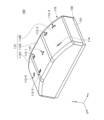
- External perspective view of an input device External perspective view of an input device according to an embodiment
- External perspective view of an input device A plan view of an input device according to an embodiment
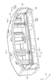
- Side view of an input device An exploded perspective view of an input device according to an embodiment
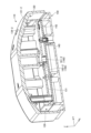
- a plan view of a case included in an input device External perspective view of a case included in an input device according to an embodiment
- a cross-sectional perspective view taken along a line II of an input device to an embodiment
- a cross-sectional perspective view taken along a line II-II of an input device A cross-sectional perspective view taken along a line III-III of an input device according to an embodiment
- a cross-sectional perspective view taken along the IV-IV cross-sectional line of an input device An enlarged view of a part of Figure 13 (P1 section)
- FIG. 3 is a plan view of the input device 100 according to one embodiment.
- FIG. 3 is a plan view of the input device 100 according to one embodiment.
- FIG. 4 is a side view of the input device 100 according to one embodiment.
- FIG. 5 is an exploded perspective view of the input device 100 according to one embodiment.
- the X-axis direction will be referred to as the left-right direction
- the Y-axis direction will be referred to as the front-back direction
- the Z-axis direction will be referred to as the up-down direction
- the positive direction of the X-axis is defined as the right direction
- the positive direction of the Y-axis is defined as the forward direction
- the positive direction of the Z-axis is defined as the upward direction.
- the input device 100 shown in FIGS. 1 to 5 is, for example, a device that is mounted in the interior of a vehicle such as an automobile and receives touch operations and pressing operations from an operator.
- the input device 100 includes an operation panel 110, a holder 120, a first housing 130, a substrate 140, a second housing 150, and an electrostatic detection electrode sheet 180.
- the operation panel 110 is a resin member that accepts touch operations and press operations from the operator.
- the operation panel 110 is box-shaped with a hollow structure, and generally has a rectangular parallelepiped shape with a rectangular opening 111 at the lower surface.
- the operation panel 110 has a rectangular shape whose longitudinal direction is the front-rear direction (Y-axis direction) when viewed from above.
- the operation panel 110 is swingably supported by the first housing 130. Specifically, the operation panel 110 is supported by the first housing 130 so as to be able to swing around the swing axis AX shown in FIG. 3 .
- the upper surface 112 of the operation panel 110 is configured to include a flat portion 112A, a first sloped portion 112B, and a second sloped portion 112C.
- the plane portion 112A is a central portion in the front-rear direction (Y-axis direction), and is a portion parallel to the XY plane.
- the first inclined portion 112B is a portion on the front side (positive side of the Y axis) than the flat portion 112A, and is a portion that is an inclined surface inclined downward toward the front.
- the second inclined portion 112C is a portion on the rear side (Y-axis negative side) than the flat portion 112A, and is a portion that is an inclined surface inclined backwardly.
- Areas A, B, C, D, E, F, and G are provided on the top surface 112 of the operation panel 110. Areas A, B, D, E, and G accept both touch operations and press operations from the operator. Area F does not accept press operations from the operator, but only accepts touch operations.
- a region A and a region B are provided side by side in the left-right direction (X-axis direction). Further, in area A, a display section 113-1 shaped like the alphabet "A” is provided, and in area B, a display section 113-2 shaped like the alphabet "B" is provided.
- Region D is an example of a "first operation section” provided on the front side (Y-axis positive side) of the upper surface 112.
- area D is provided with a display section 113-3 shaped like the alphabet "D”
- area E is provided with a display section 113-4 shaped like the alphabet "E”.
- a region F is provided on the right side (X-axis positive side) of the first inclined portion 112B.
- Area F is an example of a "second operation section.”
- a display section 114 shaped like the alphabet "F" is provided.
- Region G is provided at the center of the second inclined portion 112C.
- Region G is an example of a "first operation section” provided on the rear side (Y-axis negative side) of the upper surface 112.
- a display section 113-5 shaped like the alphabet "G" is provided.
- a region C is provided at the center of the flat portion 112A.
- a display section 115 shaped like the alphabet "C" is provided in area C. It should be noted that the display section 115 in area C merely displays information to enhance the design, and does not accept operations from the operator.
- the operation panel 110 is composed of a white resin and a black coating layer, and the display sections A to G are formed by removing a portion of the black coating layer using a technique such as laser processing.
- a through hole is provided in a portion of the holder 120 corresponding to the display sections A to G, so that when the light emitting elements 143-1 to 143-7 are turned on, the light from the light emitting elements 143-1 to 143-7 is directed to the display section A. ⁇ The back of G is illuminated.
- the holder 120 is a plate-shaped member made of resin and arranged and fixed inside the operation panel 110.
- the upper surface 120A of the holder 120 has a bent shape along the upper surface 112 of the operation panel 110.
- the holder 120 is arranged inside the operation panel 110 so as to overlap the back side of the top surface 112 of the operation panel 110.
- Holder 120 holds electrostatic detection electrode sheet 180 on its upper surface 120A.
- the electrostatic detection electrode sheet 180 has a connection part (not shown) connected to the substrate 140 and is electrically connected to the substrate 140. Thereby, the input device 100 can detect touch operations performed on areas A to B and areas D to G of the operation panel 110 using the electrostatic detection electrode sheet 180.
- the holder 120 is fixed to the operation panel 110.
- the holder 120 is swingably supported by the first housing 130. Therefore, the holder 120 and the operation panel can swing relative to the first housing 130.
- the holder 120 includes a pair of bearing holes 122A, a pair of guide ribs 171, a pressing portion 121-1, a pressing portion 121-2, and a protruding portion 161-1, which will be described in detail later.
- the bearing hole 122A has a shape that fits into the locking portion 133 of the first housing 130, supports the holder 120 and the operation panel in a swingable manner, and defines a swinging range.
- the guide rib 171 has a shape that fits into the guide groove 172 of the first housing 130 and defines a range in which the holder 120 and the operation panel swing.
- the pressing portion 121-1 is shaped to press the first pressing switch 141.
- the pressing portion 121-2 is shaped to press the second press switch 142.
- the first housing 130 is a resin member disposed below the holder 120 inside the operation panel 110.
- the first housing 130 is provided to cover the substrate 140.
- the first housing 130 swingably supports the operation panel 110 and the holder 120.
- the first housing 130 is an example of a "casing".
- the first housing 130 is provided so as to cover the substrate 140, so that the projections 161-1 and 161-2 provided on the holder 120 can be brought into contact with the first housing 130, that is, Since the protrusions 161-1 and 161-2 can be prevented from contacting the substrate 140, damage to the substrate 140 caused by the protrusions 161-1 and 161-2 can be suppressed.
- the substrate 140 is a flat member made of resin.
- the substrate 140 has a rectangular shape whose longitudinal direction is the front-rear direction (Y-axis direction) when viewed from above.
- the board 140 is provided on the lower side (Z-axis negative side) of the first housing 130 and is positioned at a predetermined height inside the peripheral wall 152 of the second housing 150 in a posture parallel to the XY plane. Placed.
- a first press switch 141 and a second press switch 142 are mounted on the upper surface 140A of the substrate 140. The first press switch 141 and the second press switch 142 detect press operations performed by the operator on the operation panel 110.
- the first press switch 141 is an example of "a press detection section that is farther from the first operation section (area E) among the two press detection sections.”
- the second press switch 142 is an example of "a press detection section that is farther from the first operation section (region G) among the two press detection sections.”
- the first press switch 141 is provided near the left front corner (the corner on the Y-axis positive side and the X-axis negative side) of the top surface 140A.
- the first press switch 141 is provided approximately at the center of the rear portion of the upper surface 140A (portion on the Y-axis negative side). Further, on the upper surface 140A of the substrate 140, light emitting elements 143-1 to 143-7 are mounted.
- the second housing 150 is a resin member disposed at the bottom of the input device 100.
- the second housing 150 has a flat portion 151 and a peripheral wall portion 152.
- the plane portion 151 is a planar portion parallel to the XY plane.
- the peripheral wall portion 152 is provided so as to protrude upward (in the Z-axis positive direction) from the upper surface of the flat portion 151, and is a wall-shaped portion having a rectangular shape when viewed from above (in the Z-axis positive direction).
- two pedestals 153 are provided on the upper surface of the plane portion 151 and inside the peripheral wall portion 152, side by side in the front-rear direction.
- the pedestal portion 153 has a cylindrical shape and supports the substrate 140 at a predetermined height position from below (Z-axis negative side).
- the second casing 150 is fixed to the first casing 130 with two fixing screws 154 passing through the pedestal 153 while being coupled to the lower side of the first casing 130 .
- the input device 100 when any of the areas A, B, and G of the operation panel 110 is pressed, the holder 120 and the right rear corner of the operation panel 110 (X-axis positive side The holder 120 and the operation panel 110 swing around the swing axis AX such that the corner on the negative side of the Y-axis moves toward the substrate 140. Thereby, the input device 100 can detect that the first press switch 141 is pressed and that any of the areas A, B, and G is pressed.
- the input device 100 when either the area C or the area D of the operation panel 110 is pressed, the input device 100 operates at the front left corner of the holder 120 and the operation panel 110 (the corner on the negative side of the X axis and the positive side of the Y axis).
- the holder 120 and the operation panel 110 swing around the swing axis AX so that the holder 120 and the operation panel 110 move toward the substrate 140 side.
- the input device 100 can detect that the second press switch 142 is pressed and either area C or area D is pressed.
- the input device 100 includes a suppression mechanism 160, which will be described later, so that when the area F of the operation panel 110 is pressed, the holder 120 and the operation panel 110 are prevented from swinging, and the first press switch 141 and the first press switch 141 and the first press switch 141 are The two-press switch 142 is not pressed.
- the input device 100 includes a suppression mechanism 160, which will be described later, so that when the symbol display section 115 of the operation panel 110 is pressed, the holder 120 and the operation panel 110 are prevented from swinging, and the first press switch 141 is And the second press switch 142 is not pressed.
- the input device 100 can be configured not to detect the erroneous operation.
- the region F is provided on the swing axis AX.
- the operation panel 110 and the holder 120 are difficult to swing, that is, the first press switch 141 and the second press switch 142 are It is possible to prevent the device from being pressed by the user.
- FIG. 6 is a plan view of the first housing 130 included in the input device 100 according to one embodiment.
- FIG. 7 is an external perspective view of the first housing 130 included in the input device 100 according to one embodiment.
- the first housing 130 includes a planar portion 131 parallel to the XY plane, and a wall-shaped frame portion 132 surrounding the planar portion 131 and perpendicular to the XY plane. and has. Further, the first housing 130 has a pair of cylindrical locking portions 133 on the swing axis AX on the side surface of the frame portion 132, which protrude toward the axial direction of the swing axis AX.
- the first housing 130 has a side surface of the right front corner of the frame 132 (the corner on the positive side of the X-axis and the positive side of the Y-axis) and a left side surface of the frame 132 (the corner on the negative side of the X-axis).
- a pair of support surfaces 132A orthogonal to the swing axis AX are formed at an intermediate position in the front-rear direction (Y-axis direction) of the side surface).
- the first housing 130 is provided with a pair of cylindrical locking portions 133 that protrude toward the axial direction of the swing axis AX on each of the pair of support surfaces 132A.
- the pair of locking portions 133 have a cylindrical shape, are formed at the ends of the first housing 130, and have a shape that constitutes the swing axis AX.
- the pair of locking portions 133 are fitted into the pair of bearing holes 122A provided in the holder 120, thereby locking the holder 120 and the operation panel 110 so as to be swingable around the swing axis AX. Further, since the pair of locking portions 133 swing around the swing axis AX while contacting surfaces 122Ac and 122Ad, which will be described in detail later, the holder 120 and the operation panel 110 swing around the swing axis AX. It is held so that it can swing in the direction of the center of movement (swing direction).
- each of the locking portions 133 comes into contact with the surface 122Ac and the surface 122Ad, so that the holder 120 and the operation panel 110 are prevented from rotating in the direction of rotation about the Z-axis direction. Furthermore, each of the locking portions 133 can move upward (in the Z-axis positive direction) until it comes into contact with a surface 122Aa, which will be described in detail later. Therefore, if there is no element to suppress the transition other than the surface 122Aa, the locking portion 133 can transition downward (in the Z-axis negative direction) until it comes into contact with the surface 122Ab.
- the holder 120 and the operation panel 110 are supported by the two press switches (141, 142) with the vertical movement limit position defined by the surface 122Aa and the surface 122Ab, and are moved upward by the restoring force from the two press switches. energized towards.
- the holder 120 and the operation panel 110 are restricted from rotating only in the direction of rotation about the Z-axis direction, and at the same time are allowed to swing in all other directions. There is. Note that, as shown in FIG. 17, in this embodiment, since the protrusion 161-1 is provided near the area F, the protrusion 161-1 is connected to the locking part provided near the area F. 133 is inhibited from transitioning downward. Therefore, when region F is pressed, holder 120 and operation panel 110 do not swing.
- two through holes 134-1 and 134-2 are formed in the plane part 131 of the first housing 130, and have a circular shape when viewed from above. ing.
- the through hole 134-1 is formed at a position overlapping the pressing portion 121-1 provided on the holder 120 and the first press switch 141 mounted on the substrate 140 when viewed from above.
- the through hole 134-1 allows the holder 120 and the operation panel 110 to swing ( The right rear corner portion moves toward the substrate 140 (swinging), and the pressing section 121-1 can press the first pressing switch 141 by the swinging of the holder 120 and the operation panel 110.
- the through hole 134-2 is formed at a position overlapping the pressing portion 121-2 provided on the holder 120 and the second press switch 142 mounted on the substrate 140 when viewed from above.
- the through hole 134-2 allows the holder 120 and the operation panel 110 to swing (left front corner) when either the region C or the region D of the operation panel 110 is pressed by passing the pressing portion 121-2 through the through hole 134-2.
- the second press switch 142 can be pressed by the second press switch 142 by the second press switch 142 by the second press switch 142 by the second press switch 142 by the second press switch 142.
- the flat part 131 of the first housing 130 has two concave contact parts 162-1 and 162-2 that have a circular shape when viewed from above. is formed.
- the contact portion 162-1 constitutes the restraining mechanism 160, and is located in the area on the front right side of the flat portion 131 (region on the positive side of the X axis and the positive side of the Y axis) and the holder in a plan view from above. It is formed at a position overlapping with the protrusion 161-1 provided on the portion 120.
- the contact portion 162-1 prevents the holder 120 and the operation panel 110 from swinging by contacting the projection 161-1 when the region F of the operation panel 110 is pressed, and prevents the first press switch 141 from swinging. And the second press switch 142 is prevented from being pressed.
- the contact portion 162-2 is formed at approximately the center of the flat portion 131 and at a position overlapping with the protrusion 161-2 provided on the holder 120 when viewed from above.
- the contact section 162-2 comes into contact with the protrusion 161-2, thereby suppressing the swinging of the holder 120 and the operation panel 110, and prevents the first press.
- the switch 141 and the second press switch 142 are prevented from being pressed.
- the plane portion 131 of the first casing 130 is provided with rectangular cylindrical portions 135-1 to 135-6 and a rectangular opening 136. There is.
- the cylindrical portion 135-1 is provided at a position overlapping the area A of the operation panel 110 and the light emitting element 143-1 mounted on the substrate 140 in a plan view from above. By guiding the emitted light to area A, the display section 113-1 in area A is caused to emit light.
- the cylindrical portion 135-2 is provided at a position overlapping area B of the operation panel 110 and the light emitting element 143-2 mounted on the substrate 140 in a plan view from above. By guiding the emitted light to region B, the display section 113-2 in region B is caused to emit light.
- the cylindrical portion 135-3 is provided at a position overlapping the area C of the operation panel 110 and the light emitting element 143-3 mounted on the substrate 140 in a plan view from above. By guiding the emitted light to area C, the display section 113-3 in area C is caused to emit light.
- the cylindrical portion 135-4 is provided at a position overlapping the area D of the operation panel 110 and the light emitting element 143-4 mounted on the substrate 140 in a plan view from above. By guiding the emitted light to area D, the display section 113-4 in area D is caused to emit light.
- the cylindrical portion 135-5 is provided at a position overlapping the area G of the operation panel 110 and the light emitting element 143-5 mounted on the substrate 140 in a plan view from above. By guiding the emitted light to region G, the display section 113-5 in region G is caused to emit light.
- the cylindrical portion 135-6 is provided at a position overlapping the area F of the operation panel 110 and the light emitting element 143-6 mounted on the substrate 140 in a plan view from above. By guiding the emitted light to the area F, the display section 114 in the area F is caused to emit light.
- the opening 136 is provided at a position overlapping the symbol display section 115 of the operation panel 110, the cylindrical section 123 of the holder 120, and the light emitting element 143-7 mounted on the substrate 140 when viewed from above. , the symbol display section 115 is caused to emit light by guiding the light emitted from the light emitting element 143-7 to the symbol display section 115 through the cylindrical portion 123 of the holder 120.
- the movable amount of the cylinder parts 135-1 to 135-6 in the vertical direction (Z-axis direction) when the operation panel 110 swings is the same as that of the pressing parts 121-1 and 121 when the operation panel 110 swings.
- the amount of movement in the vertical direction (Z-axis direction) is greater than -2. Accordingly, when the operation panel 110 swings, the input device 100 moves the cylindrical portions 135-1 to 135-6 in the vertical direction (Z-axis direction) only by the first movement by the pressing portions 121-1 and 121-2. It is designed so that it does not interfere with the pressing of the first press switch 141 and the second press switch 142.
- FIG. 10 is a cross-sectional perspective view taken along the line II (see FIG. 3) of the input device 100 according to one embodiment.
- FIG. 11 is a cross-sectional perspective view taken along the line II-II (see FIG. 3) of the input device 100 according to one embodiment.
- the first housing 130 has a pair of locking parts 133.
- the holder 120 has a pair of bearing parts 122 that are provided to hang down from the lower surface of the holder 120.
- Each of the pair of bearing parts 122 has a bearing hole 122A near the lower end. Then, as shown in FIG. 9, when the first housing 130 is assembled to the holder 120, each of the pair of locking parts 133 is fitted into each of the pair of bearing holes 122A.
- the holder 120 is supported while being urged upward (in the Z-axis positive direction) by the restoring force of the first press switch 141 and the second press switch 142.
- the bearing hole 122A of the holder 120 is constituted by surfaces 122Aa to 122Ad, and has a vertically elongated rectangular shape.
- the surface 122Aa and the surface 122Ab are opposed to each other.
- the surface 122Aa is a surface that defines the limit position when the holder 120 moves downward.
- the surface 122Ab is a surface that defines the limit position when the holder 120 moves upward.
- the surface 122Ac and the surface 122Ad face each other, and the distance therebetween is set to be approximately the same as the dimension of the locking portion 133.
- the holder 120 When the first housing 130 is assembled to the holder 120, the holder 120 is urged upward by the first press switch 141 and the second press switch 142, so that the surface 122Ab of the holder 120 and the first housing 130 are It is in contact with the locking portion 133. Further, for the same reason, the surface 122Aa and the locking portion 133 are separated by a distance D3 or a distance D4. As a result, the holder 120 and the operation panel 110 do not rotate around the Z-axis direction because the locking portion 133 is restricted by the surface 122Ac and the surface 122Ad, and can swing in all other directions. It is set in.
- the holder 120 and the operation panel 110 are supported to be swingable around the swing axis AX by the pair of locking portions 133, and can be moved vertically by distances D3 and D4. Supported. Therefore, the holder 120 and the operation panel 110 can swing about the swing axis AX until they stop receiving the reaction force from the first push switch 141 or the second push switch 142.
- the distance D3 and the distance D4 are set to be substantially the same as the operation stroke of the two press switches (141, 142) from the neutral state until they are pressed and turned on.
- the holder 120 and the operation panel 110 are arranged in a direction parallel to the swing axis AX and a plane parallel to the up-down direction (Z-axis direction) in the range until the locking part 133 is regulated by the surface 122Aa or the surface 122Ab. can be swung in any direction.
- the range in which the holder 120 and the operation panel 110 swing in a direction parallel to the swing axis AX and a plane parallel to the vertical direction (Z-axis direction) is when the second press switch 142 is pressed from the neutral state and turned ON. It is preferable that the switch stroke be set smaller than the switch stroke when the switch stroke occurs.
- the range in which the holder 120 and the operation panel 110 swing in a direction parallel to the swing axis AX and a plane parallel to the vertical direction (Z-axis direction) is limited to the range in which the holder 120 and the operation panel 110 It is set smaller than the range of swing around the center.
- the holder 120 is provided with cylindrical protrusions 161-1 and 161-2 that hang down from the bottom surface of the holder 120.
- the protrusion 161-1 constitutes the restraining mechanism 160, and is located in the area on the right front side (region on the X-axis positive side and the Y-axis positive side) of the holder 120, and in a plan view from above. It is provided at a position overlapping with the contact portion 162-1 of the first housing 130. As shown in FIGS. 6 and 7, in a plan view from above, the contact portion 162-1 is provided at a position overlapping the swing axis AX, and is located from the center of the pair of locking portions 133. It is provided at a position close to area F. As shown in FIGS.
- the range in which the holder 120 and the operation panel 110 swing in a direction parallel to the swing axis AX and a plane parallel to the vertical direction (Z-axis direction) is the range in which the holder 120 and the operation panel 110 swing in other directions.
- region F of operation panel 110 is set smaller than , and under that condition the above-mentioned deterrent effect occurs. Therefore, when region F of operation panel 110 is pressed, holder 120 and operation panel 110 hardly change. Further, the feeling generated by the contact between the protrusion 161-1 and the contact portion 162-1 is fed back to the operator's fingers as a clear sense of resistance. Note that when region E or region G is pressed, protrusion 161-1 does not contact contact portion 162-1, and therefore does not inhibit the swinging of holder 120 and operation panel 110. Therefore, the operator can infer from the operation feel that area F is an operation section that does not support pressing operations.
- the protrusion 161-2 constitutes the deterrent mechanism 160, and is provided at approximately the center of the holder 120 and at a position overlapping with the contact portion 162-2 of the first housing 130 when viewed from above. It is being As shown in FIGS. 9 and 11, when the first housing 130 is assembled to the holder 120, the lower end surface of the protruding portion 161-2 is slightly above the contact portion 162-2 of the first housing 130. located apart from each other. As a result, when the symbol display section 115 of the operation panel 110 is pressed, the protrusion 161-2 comes into contact with the contact section 162-2, thereby suppressing the swinging of the holder 120 and the operation panel 110. The first press switch 141 and the second press switch 142 are prevented from being pressed. Note that when region E is pressed, protrusion 161-2 does not contact contact portion 162-2, and therefore does not inhibit the swinging of holder 120 and operation panel 110.
- the holder 120 is provided with cylindrical pressing portions 121-1 and 121-2 that hang down from the bottom surface of the holder 120.
- the pressing portion 121-1 is located approximately at the center in the left-right direction (X-axis direction) of the rear side (Y-axis negative side) area of the holder 120, and at the first housing 130 in a plan view from above. It is provided at a position overlapping with the through hole 134-1.
- the lower end surface of the pressing part 121-1 is slightly above the first pressing switch 141 passing through the through hole 134-1. located apart from each other.
- the pressing section 121-1 presses the first press switch 141 by swinging the holder 120 and the operation panel 110. can.
- the pressing portion 121-2 is located near the left front corner of the holder 120 (the corner on the negative side of the X axis and the positive side of the Y axis) and in the vicinity of the through hole 134- of the first housing 130 when viewed from above. It is located at a position that overlaps with 2. As shown in FIG. 9, when the first housing 130 is assembled to the holder 120, the lower end surface of the pressing part 121-2 is slightly above the second pressing switch 142 passing through the through hole 134-2. located apart from each other. Thereby, the pressing part 121-2 can press the second press switch 142 by swinging the holder 120 and the operation panel 110 when either the area D or the area E of the operation panel 110 is pressed. do.
- FIG. 12 is a cross-sectional perspective view taken along the line III--III (see FIG. 4) of the input device 100 according to one embodiment.
- the input device 100 includes a guide mechanism 170.
- the guide mechanism 170 includes a pair of guide ribs 171 that are provided to hang down from the lower surface of the holder 120, and a pair of guide grooves 172 that are vertically provided. As shown in FIG. 12, in the guide mechanism 170, a pair of guide ribs 171 engage with a pair of guide grooves 172, thereby guiding the movement of the holder 120 and the operation panel 110 in the vertical direction (X-axis direction). Ru.
- a line L1 connecting the pair of guide ribs 171 is substantially orthogonal to the swing axis AX.
- the input device 100 can guide the swinging of the holder 120 and the operation panel 110 around the swing axis AX, and can also guide the swinging of the holder 120 and the operation panel 110 in the axial direction of the swing axis AX. The tilt can be locked.
- FIG. 13 is a cross-sectional perspective view taken along the IV-IV cross-sectional line (see FIG. 3) of the input device 100 according to one embodiment.
- the locking portion 133 of the first housing 130 is fitted into the bearing hole 122A of the holder 120, thereby making the holder 120 and the operation panel 110 swingable around the swing axis AX. to lock.
- the locking portion 133 constitutes a restraining mechanism 160.
- the width of the bearing hole 122A is approximately the same as the diameter of the locking part 133, but the vertical width is slightly larger than the diameter of the locking part 133. Therefore, the bearing hole 122A can be slightly moved in the vertical direction (Z-axis direction) within the bearing hole 122A. As a result, the input device 100 according to the embodiment can move the holder 120 and the operation panel 110 against the first housing 130 in the vertical direction ( It can be moved slightly in the Z-axis direction).
- FIG. 17 shows the swing axis AX, region E, region G, region F, first press switch 141, second press switch 142, and protrusion 161-1 in the input device 100 according to one embodiment.
- FIG. 17 shows the swing axis AX, region E, region G, region F, first press switch 141, second press switch 142, and protrusion 161-1 in the input device 100 according to one embodiment.
- the swing axis AX connecting the two locking portions 133 intersects the line connecting the region E and the first press switch 141 in a plan view from above. It also intersects the line connecting region G and second press switch 142. In other words, in a plan view from above, the swing axis AX is between the first operation section 113 and the one of the first press switch 141 and the second press switch 142 that is farther from the first operation section 113, intersects the line connecting the
- the operation panel 110 selects the first press switch 141 which is farther from the area E of the two press switches (141, 142) in a plan view from above. Swings using the apex as a fulcrum. At that time, the second press switch 142 is pressed by the holder 120, and a signal related to press detection is generated.
- the operation panel 110 selects the second press switch that is farther from the area G of the two press switches (141, 142) in a plan view from above. 142 as a fulcrum. At this time, the first press switch 141 is pressed by the holder 120, and a signal related to press detection is generated.
- the swing axis AX intersects a line L2 connecting the region D and the first press switch 141 that is far from the region D.
- the protrusion 161-1 is provided at a position overlapping the swing axis AX when viewed from above.
- the input device 100 can enhance the effect of suppressing the pressing of the first press switch 141 and the second press switch 142 when the region F is pressed.
- the input device 100 is configured such that the first press switch 141 and the second press switch 142 have a longer distance to the region F in a plan view from above.
- the distance D1 between the push switch 141 and the protrusion 161-1 is larger than the distance D2 between the protrusion 161-1 and the area F.
- the input device 100 has an effect of suppressing the swinging of the operation panel 110 due to the press on the area F, and an effect of not suppressing the swing of the operation panel 110 due to the press on the area E. can be increased.
- the operation panel 110 selects the first of the two press switches (141, 142) which is farther from the area F in a plan view from above (in the Z-axis positive direction).
- the push switch 141 swings around the apex of the push switch 141 as a fulcrum, but the protrusion 161-1 prevents the operation panel 110 from swinging, and the second push switch 142, which is closer to the area F, moves when the area F is pressed. It doesn't detect that.
- the input device 100 includes a housing and an operation panel that receives a touch operation and a pressing operation from an operator, and an operation panel that is swingably supported with respect to the housing. 110, a substrate 140 housed in a housing, an electrostatic detection electrode for detecting a touch operation, and a first press switch 141 and a second press switch 142 for detecting a press operation.
- the operation section includes a first operation section (areas E, G) that accepts touch operations and pressing operations, and a second operation section (area F) that accepts only touch operations.
- a deterrent mechanism 160 that differentiates the operation in which the operation panel 110 moves toward the substrate 140 when is pressed and the operation in which the operation panel 110 moves toward the substrate 140 when the second operation section (area F) is pressed. has.
- the input device 100 when the second operation section (area F) is pressed by mistake, the operation of moving the operation panel 110 toward the board 140 is E, G), the operator can recognize that he or she has mistakenly pressed the second operation section (area F) based on this difference in operation. Therefore, according to the input device 100 according to one embodiment, erroneous operations of the first press switch 141 and the second press switch 142 can be suppressed.
- the deterrent mechanism 160 includes a protrusion 161-1 extending from the operation panel 110 toward the housing, and the protrusion 161-1 is connected to the second operation portion ( When the area F) is pressed, it comes into contact with the contact part 162-1 of the casing to suppress the swinging of the operation panel 110, and when the first operation part (areas E, G) is pressed, the operation panel 110 is pressed. Does not suppress rocking.
- the input device 100 when the input device 100 according to the embodiment performs a normal operation on the first operation section (areas E, G), the swinging of the operation panel 110 is not hindered, and the second operation section ( When an erroneous operation is performed on area F), the swinging of the operation panel 110 can be suppressed.
- Input device 110 Operation panel 111 Opening 112 Top surface 112A Plane portion 112B First sloped portion 112C Second sloped portion 113-1 to 113-5, 114, 115 Display portion 120 Holder 120A Top surface 121-1, 121-2 Pressing portion 122 Bearing portion 122A Bearing hole 122Aa surface 122Ab surface 122Ac surface 122Ad surface 123 Cylindrical portion 130 First housing 131 Plane portion 132 Frame portion 132A Support surface 133 Locking portion 134-1, 134-2 Through holes 135-1 to 135-6 Cylinder part 136 Opening part 140 Board 140A Top surface 141 First press switch 142 Second press switch 143-1 to 143-7 Light emitting element 150 Second housing 151 Plane part 152 Surrounding wall part 153 Pedestal part 160 Inhibition mechanism 161-1, 161 -2 Projection 162-1, 162-2 Contact portion 170 Guide mechanism 171 Guide rib 172 Guide groove 180 Electrostatic detection electrode sheet A, B, C, D, E, F, G Area AX Swing axis
Landscapes
- Engineering & Computer Science (AREA)
- General Engineering & Computer Science (AREA)
- Theoretical Computer Science (AREA)
- Human Computer Interaction (AREA)
- Physics & Mathematics (AREA)
- General Physics & Mathematics (AREA)
- Microelectronics & Electronic Packaging (AREA)
- Switch Cases, Indication, And Locking (AREA)
- Switches With Compound Operations (AREA)
Priority Applications (4)
| Application Number | Priority Date | Filing Date | Title |
|---|---|---|---|
| JP2024507597A JP7601314B2 (ja) | 2022-03-15 | 2023-02-14 | 入力装置 |
| CN202380021144.2A CN118679546A (zh) | 2022-03-15 | 2023-02-14 | 输入装置 |
| DE112023001388.8T DE112023001388T5 (de) | 2022-03-15 | 2023-02-14 | Eingabevorrichtung |
| US18/787,041 US12393288B2 (en) | 2022-03-15 | 2024-07-29 | Input device |
Applications Claiming Priority (2)
| Application Number | Priority Date | Filing Date | Title |
|---|---|---|---|
| JP2022040659 | 2022-03-15 | ||
| JP2022-040659 | 2022-03-15 |
Related Child Applications (1)
| Application Number | Title | Priority Date | Filing Date |
|---|---|---|---|
| US18/787,041 Continuation US12393288B2 (en) | 2022-03-15 | 2024-07-29 | Input device |
Publications (1)
| Publication Number | Publication Date |
|---|---|
| WO2023176248A1 true WO2023176248A1 (ja) | 2023-09-21 |
Family
ID=88022869
Family Applications (1)
| Application Number | Title | Priority Date | Filing Date |
|---|---|---|---|
| PCT/JP2023/004909 Ceased WO2023176248A1 (ja) | 2022-03-15 | 2023-02-14 | 入力装置 |
Country Status (5)
| Country | Link |
|---|---|
| US (1) | US12393288B2 (https=) |
| JP (1) | JP7601314B2 (https=) |
| CN (1) | CN118679546A (https=) |
| DE (1) | DE112023001388T5 (https=) |
| WO (1) | WO2023176248A1 (https=) |
Citations (2)
| Publication number | Priority date | Publication date | Assignee | Title |
|---|---|---|---|---|
| JPS5126371U (https=) * | 1974-08-14 | 1976-02-26 | ||
| JP2009301854A (ja) * | 2008-06-12 | 2009-12-24 | Tokai Rika Co Ltd | スイッチ装置 |
Family Cites Families (3)
| Publication number | Priority date | Publication date | Assignee | Title |
|---|---|---|---|---|
| US5430261A (en) * | 1994-01-18 | 1995-07-04 | Eaton Corporation | Switch assembly including sequential switch rocker/lever operating mechanism |
| JP2006294322A (ja) * | 2005-04-07 | 2006-10-26 | Matsushita Electric Ind Co Ltd | スイッチ装置 |
| JP7185611B2 (ja) | 2019-10-30 | 2022-12-07 | 東洋電装株式会社 | シーソースイッチ |
-
2023
- 2023-02-14 WO PCT/JP2023/004909 patent/WO2023176248A1/ja not_active Ceased
- 2023-02-14 DE DE112023001388.8T patent/DE112023001388T5/de active Pending
- 2023-02-14 JP JP2024507597A patent/JP7601314B2/ja active Active
- 2023-02-14 CN CN202380021144.2A patent/CN118679546A/zh active Pending
-
2024
- 2024-07-29 US US18/787,041 patent/US12393288B2/en active Active
Patent Citations (2)
| Publication number | Priority date | Publication date | Assignee | Title |
|---|---|---|---|---|
| JPS5126371U (https=) * | 1974-08-14 | 1976-02-26 | ||
| JP2009301854A (ja) * | 2008-06-12 | 2009-12-24 | Tokai Rika Co Ltd | スイッチ装置 |
Also Published As
| Publication number | Publication date |
|---|---|
| CN118679546A (zh) | 2024-09-20 |
| US12393288B2 (en) | 2025-08-19 |
| US20240385700A1 (en) | 2024-11-21 |
| DE112023001388T5 (de) | 2024-12-24 |
| JP7601314B2 (ja) | 2024-12-17 |
| JPWO2023176248A1 (https=) | 2023-09-21 |
Similar Documents
| Publication | Publication Date | Title |
|---|---|---|
| US7283122B2 (en) | Input device including a scroll wheel assembly | |
| JP2009004140A (ja) | 多方向操作部品 | |
| JP4596020B2 (ja) | 車両用操作装置 | |
| JP5459328B2 (ja) | 手書入力機能付き操作装置 | |
| WO2023176248A1 (ja) | 入力装置 | |
| JP2018060306A (ja) | 入力装置及び電子機器 | |
| JP2021072190A (ja) | シーソースイッチ | |
| JP6732671B2 (ja) | パネル装置およびパネル装置の組立方法 | |
| EP1566822B1 (en) | Multidirectional input device | |
| EP1884858A1 (en) | Tilting operation type input device | |
| JP6502868B2 (ja) | コンビネーションスイッチレバー | |
| JP2023111813A (ja) | 多方向操作スイッチ装置 | |
| JP4624973B2 (ja) | シフト装置 | |
| JP2025107076A (ja) | 入力装置 | |
| US20240267048A1 (en) | Input Device | |
| JP7620375B2 (ja) | 入力装置 | |
| JP3106017B2 (ja) | 接点切換表示機能付き波動スイッチ | |
| JP6652818B2 (ja) | 操作入力装置 | |
| CN111030666A (zh) | 可实现多方向振动的触摸开关及包含其的汽车 | |
| JP2024107900A (ja) | 入力装置 | |
| JP2020004612A (ja) | スイッチ装置 | |
| JP6652817B2 (ja) | 操作入力装置 | |
| WO2026048479A1 (ja) | 入力装置 | |
| KR20230024276A (ko) | 차량용 조작유닛 | |
| WO2022118546A1 (ja) | スイッチインターフェース |
Legal Events
| Date | Code | Title | Description |
|---|---|---|---|
| 121 | Ep: the epo has been informed by wipo that ep was designated in this application |
Ref document number: 23770209 Country of ref document: EP Kind code of ref document: A1 |
|
| WWE | Wipo information: entry into national phase |
Ref document number: 2024507597 Country of ref document: JP |
|
| WWE | Wipo information: entry into national phase |
Ref document number: 202380021144.2 Country of ref document: CN |
|
| WWE | Wipo information: entry into national phase |
Ref document number: 112023001388 Country of ref document: DE |
|
| 122 | Ep: pct application non-entry in european phase |
Ref document number: 23770209 Country of ref document: EP Kind code of ref document: A1 |