WO2023176248A1 - Input device - Google Patents
Input device Download PDFInfo
- Publication number
- WO2023176248A1 WO2023176248A1 PCT/JP2023/004909 JP2023004909W WO2023176248A1 WO 2023176248 A1 WO2023176248 A1 WO 2023176248A1 JP 2023004909 W JP2023004909 W JP 2023004909W WO 2023176248 A1 WO2023176248 A1 WO 2023176248A1
- Authority
- WO
- WIPO (PCT)
- Prior art keywords
- section
- operation panel
- press
- input device
- pressed
- Prior art date
Links
- 239000000758 substrate Substances 0.000 claims abstract description 40
- 238000001514 detection method Methods 0.000 claims abstract description 24
- 230000001629 suppression Effects 0.000 claims description 3
- 230000005764 inhibitory process Effects 0.000 abstract description 2
- 239000011347 resin Substances 0.000 description 6
- 229920005989 resin Polymers 0.000 description 6
- 230000000694 effects Effects 0.000 description 5
- 230000002093 peripheral effect Effects 0.000 description 4
- NJPPVKZQTLUDBO-UHFFFAOYSA-N novaluron Chemical compound C1=C(Cl)C(OC(F)(F)C(OC(F)(F)F)F)=CC=C1NC(=O)NC(=O)C1=C(F)C=CC=C1F NJPPVKZQTLUDBO-UHFFFAOYSA-N 0.000 description 3
- 230000000452 restraining effect Effects 0.000 description 3
- 239000011247 coating layer Substances 0.000 description 2
- 238000009434 installation Methods 0.000 description 2
- 238000000034 method Methods 0.000 description 2
- 230000007935 neutral effect Effects 0.000 description 2
- 230000007704 transition Effects 0.000 description 2
- 238000010586 diagram Methods 0.000 description 1
- 238000012986 modification Methods 0.000 description 1
- 230000004048 modification Effects 0.000 description 1
- 230000001105 regulatory effect Effects 0.000 description 1
Images


Classifications
-
- H—ELECTRICITY
- H01—ELECTRIC ELEMENTS
- H01H—ELECTRIC SWITCHES; RELAYS; SELECTORS; EMERGENCY PROTECTIVE DEVICES
- H01H23/00—Tumbler or rocker switches, i.e. switches characterised by being operated by rocking an operating member in the form of a rocker button
- H01H23/02—Details
- H01H23/12—Movable parts; Contacts mounted thereon
- H01H23/16—Driving mechanisms
Definitions
- the present invention relates to an input device.
- Patent Document 1 listed below includes a case, a knob that has two push operation parts and is movably locked to the housing by a fulcrum part provided on the side wall of the case, and two switches.
- a seesaw switch is disclosed.
- An input device includes a housing, an operation panel that receives touch operations and press operations from an operator, and is supported in a swingable manner with respect to the housing, and an operation panel that is housed in the housing.
- An input device comprising a substrate that detects a touch operation, an electrostatic detection electrode that detects a touch operation, and a press detection section that detects a press operation, the operation section including a first operation section that receives both a touch operation and a press operation. and a second operation section that accepts only touch operations without accepting press operations, and includes an operation in which the operation panel moves toward the board when the first operation section is pressed, and an operation when the second operation section is pressed. It has a deterrent mechanism that makes the operation of moving the panel toward the substrate different.
- the input device it is possible to suppress erroneous operation of the press detection section.
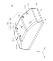
- External perspective view of an input device External perspective view of an input device according to an embodiment
- External perspective view of an input device A plan view of an input device according to an embodiment
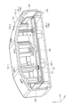
- Side view of an input device An exploded perspective view of an input device according to an embodiment
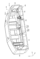
- a plan view of a case included in an input device External perspective view of a case included in an input device according to an embodiment
- a cross-sectional perspective view taken along a line II of an input device to an embodiment
- a cross-sectional perspective view taken along a line II-II of an input device A cross-sectional perspective view taken along a line III-III of an input device according to an embodiment
- a cross-sectional perspective view taken along the IV-IV cross-sectional line of an input device An enlarged view of a part of Figure 13 (P1 section)
- FIG. 3 is a plan view of the input device 100 according to one embodiment.
- FIG. 3 is a plan view of the input device 100 according to one embodiment.
- FIG. 4 is a side view of the input device 100 according to one embodiment.
- FIG. 5 is an exploded perspective view of the input device 100 according to one embodiment.
- the X-axis direction will be referred to as the left-right direction
- the Y-axis direction will be referred to as the front-back direction
- the Z-axis direction will be referred to as the up-down direction
- the positive direction of the X-axis is defined as the right direction
- the positive direction of the Y-axis is defined as the forward direction
- the positive direction of the Z-axis is defined as the upward direction.
- the input device 100 shown in FIGS. 1 to 5 is, for example, a device that is mounted in the interior of a vehicle such as an automobile and receives touch operations and pressing operations from an operator.
- the input device 100 includes an operation panel 110, a holder 120, a first housing 130, a substrate 140, a second housing 150, and an electrostatic detection electrode sheet 180.
- the operation panel 110 is a resin member that accepts touch operations and press operations from the operator.
- the operation panel 110 is box-shaped with a hollow structure, and generally has a rectangular parallelepiped shape with a rectangular opening 111 at the lower surface.
- the operation panel 110 has a rectangular shape whose longitudinal direction is the front-rear direction (Y-axis direction) when viewed from above.
- the operation panel 110 is swingably supported by the first housing 130. Specifically, the operation panel 110 is supported by the first housing 130 so as to be able to swing around the swing axis AX shown in FIG. 3 .
- the upper surface 112 of the operation panel 110 is configured to include a flat portion 112A, a first sloped portion 112B, and a second sloped portion 112C.
- the plane portion 112A is a central portion in the front-rear direction (Y-axis direction), and is a portion parallel to the XY plane.
- the first inclined portion 112B is a portion on the front side (positive side of the Y axis) than the flat portion 112A, and is a portion that is an inclined surface inclined downward toward the front.
- the second inclined portion 112C is a portion on the rear side (Y-axis negative side) than the flat portion 112A, and is a portion that is an inclined surface inclined backwardly.
- Areas A, B, C, D, E, F, and G are provided on the top surface 112 of the operation panel 110. Areas A, B, D, E, and G accept both touch operations and press operations from the operator. Area F does not accept press operations from the operator, but only accepts touch operations.
- a region A and a region B are provided side by side in the left-right direction (X-axis direction). Further, in area A, a display section 113-1 shaped like the alphabet "A” is provided, and in area B, a display section 113-2 shaped like the alphabet "B" is provided.
- Region D is an example of a "first operation section” provided on the front side (Y-axis positive side) of the upper surface 112.
- area D is provided with a display section 113-3 shaped like the alphabet "D”
- area E is provided with a display section 113-4 shaped like the alphabet "E”.
- a region F is provided on the right side (X-axis positive side) of the first inclined portion 112B.
- Area F is an example of a "second operation section.”
- a display section 114 shaped like the alphabet "F" is provided.
- Region G is provided at the center of the second inclined portion 112C.
- Region G is an example of a "first operation section” provided on the rear side (Y-axis negative side) of the upper surface 112.
- a display section 113-5 shaped like the alphabet "G" is provided.
- a region C is provided at the center of the flat portion 112A.
- a display section 115 shaped like the alphabet "C" is provided in area C. It should be noted that the display section 115 in area C merely displays information to enhance the design, and does not accept operations from the operator.
- the operation panel 110 is composed of a white resin and a black coating layer, and the display sections A to G are formed by removing a portion of the black coating layer using a technique such as laser processing.
- a through hole is provided in a portion of the holder 120 corresponding to the display sections A to G, so that when the light emitting elements 143-1 to 143-7 are turned on, the light from the light emitting elements 143-1 to 143-7 is directed to the display section A. ⁇ The back of G is illuminated.
- the holder 120 is a plate-shaped member made of resin and arranged and fixed inside the operation panel 110.
- the upper surface 120A of the holder 120 has a bent shape along the upper surface 112 of the operation panel 110.
- the holder 120 is arranged inside the operation panel 110 so as to overlap the back side of the top surface 112 of the operation panel 110.
- Holder 120 holds electrostatic detection electrode sheet 180 on its upper surface 120A.
- the electrostatic detection electrode sheet 180 has a connection part (not shown) connected to the substrate 140 and is electrically connected to the substrate 140. Thereby, the input device 100 can detect touch operations performed on areas A to B and areas D to G of the operation panel 110 using the electrostatic detection electrode sheet 180.
- the holder 120 is fixed to the operation panel 110.
- the holder 120 is swingably supported by the first housing 130. Therefore, the holder 120 and the operation panel can swing relative to the first housing 130.
- the holder 120 includes a pair of bearing holes 122A, a pair of guide ribs 171, a pressing portion 121-1, a pressing portion 121-2, and a protruding portion 161-1, which will be described in detail later.
- the bearing hole 122A has a shape that fits into the locking portion 133 of the first housing 130, supports the holder 120 and the operation panel in a swingable manner, and defines a swinging range.
- the guide rib 171 has a shape that fits into the guide groove 172 of the first housing 130 and defines a range in which the holder 120 and the operation panel swing.
- the pressing portion 121-1 is shaped to press the first pressing switch 141.
- the pressing portion 121-2 is shaped to press the second press switch 142.
- the first housing 130 is a resin member disposed below the holder 120 inside the operation panel 110.
- the first housing 130 is provided to cover the substrate 140.
- the first housing 130 swingably supports the operation panel 110 and the holder 120.
- the first housing 130 is an example of a "casing".
- the first housing 130 is provided so as to cover the substrate 140, so that the projections 161-1 and 161-2 provided on the holder 120 can be brought into contact with the first housing 130, that is, Since the protrusions 161-1 and 161-2 can be prevented from contacting the substrate 140, damage to the substrate 140 caused by the protrusions 161-1 and 161-2 can be suppressed.
- the substrate 140 is a flat member made of resin.
- the substrate 140 has a rectangular shape whose longitudinal direction is the front-rear direction (Y-axis direction) when viewed from above.
- the board 140 is provided on the lower side (Z-axis negative side) of the first housing 130 and is positioned at a predetermined height inside the peripheral wall 152 of the second housing 150 in a posture parallel to the XY plane. Placed.
- a first press switch 141 and a second press switch 142 are mounted on the upper surface 140A of the substrate 140. The first press switch 141 and the second press switch 142 detect press operations performed by the operator on the operation panel 110.
- the first press switch 141 is an example of "a press detection section that is farther from the first operation section (area E) among the two press detection sections.”
- the second press switch 142 is an example of "a press detection section that is farther from the first operation section (region G) among the two press detection sections.”
- the first press switch 141 is provided near the left front corner (the corner on the Y-axis positive side and the X-axis negative side) of the top surface 140A.
- the first press switch 141 is provided approximately at the center of the rear portion of the upper surface 140A (portion on the Y-axis negative side). Further, on the upper surface 140A of the substrate 140, light emitting elements 143-1 to 143-7 are mounted.
- the second housing 150 is a resin member disposed at the bottom of the input device 100.
- the second housing 150 has a flat portion 151 and a peripheral wall portion 152.
- the plane portion 151 is a planar portion parallel to the XY plane.
- the peripheral wall portion 152 is provided so as to protrude upward (in the Z-axis positive direction) from the upper surface of the flat portion 151, and is a wall-shaped portion having a rectangular shape when viewed from above (in the Z-axis positive direction).
- two pedestals 153 are provided on the upper surface of the plane portion 151 and inside the peripheral wall portion 152, side by side in the front-rear direction.
- the pedestal portion 153 has a cylindrical shape and supports the substrate 140 at a predetermined height position from below (Z-axis negative side).
- the second casing 150 is fixed to the first casing 130 with two fixing screws 154 passing through the pedestal 153 while being coupled to the lower side of the first casing 130 .
- the input device 100 when any of the areas A, B, and G of the operation panel 110 is pressed, the holder 120 and the right rear corner of the operation panel 110 (X-axis positive side The holder 120 and the operation panel 110 swing around the swing axis AX such that the corner on the negative side of the Y-axis moves toward the substrate 140. Thereby, the input device 100 can detect that the first press switch 141 is pressed and that any of the areas A, B, and G is pressed.
- the input device 100 when either the area C or the area D of the operation panel 110 is pressed, the input device 100 operates at the front left corner of the holder 120 and the operation panel 110 (the corner on the negative side of the X axis and the positive side of the Y axis).
- the holder 120 and the operation panel 110 swing around the swing axis AX so that the holder 120 and the operation panel 110 move toward the substrate 140 side.
- the input device 100 can detect that the second press switch 142 is pressed and either area C or area D is pressed.
- the input device 100 includes a suppression mechanism 160, which will be described later, so that when the area F of the operation panel 110 is pressed, the holder 120 and the operation panel 110 are prevented from swinging, and the first press switch 141 and the first press switch 141 and the first press switch 141 are The two-press switch 142 is not pressed.
- the input device 100 includes a suppression mechanism 160, which will be described later, so that when the symbol display section 115 of the operation panel 110 is pressed, the holder 120 and the operation panel 110 are prevented from swinging, and the first press switch 141 is And the second press switch 142 is not pressed.
- the input device 100 can be configured not to detect the erroneous operation.
- the region F is provided on the swing axis AX.
- the operation panel 110 and the holder 120 are difficult to swing, that is, the first press switch 141 and the second press switch 142 are It is possible to prevent the device from being pressed by the user.
- FIG. 6 is a plan view of the first housing 130 included in the input device 100 according to one embodiment.
- FIG. 7 is an external perspective view of the first housing 130 included in the input device 100 according to one embodiment.
- the first housing 130 includes a planar portion 131 parallel to the XY plane, and a wall-shaped frame portion 132 surrounding the planar portion 131 and perpendicular to the XY plane. and has. Further, the first housing 130 has a pair of cylindrical locking portions 133 on the swing axis AX on the side surface of the frame portion 132, which protrude toward the axial direction of the swing axis AX.
- the first housing 130 has a side surface of the right front corner of the frame 132 (the corner on the positive side of the X-axis and the positive side of the Y-axis) and a left side surface of the frame 132 (the corner on the negative side of the X-axis).
- a pair of support surfaces 132A orthogonal to the swing axis AX are formed at an intermediate position in the front-rear direction (Y-axis direction) of the side surface).
- the first housing 130 is provided with a pair of cylindrical locking portions 133 that protrude toward the axial direction of the swing axis AX on each of the pair of support surfaces 132A.
- the pair of locking portions 133 have a cylindrical shape, are formed at the ends of the first housing 130, and have a shape that constitutes the swing axis AX.
- the pair of locking portions 133 are fitted into the pair of bearing holes 122A provided in the holder 120, thereby locking the holder 120 and the operation panel 110 so as to be swingable around the swing axis AX. Further, since the pair of locking portions 133 swing around the swing axis AX while contacting surfaces 122Ac and 122Ad, which will be described in detail later, the holder 120 and the operation panel 110 swing around the swing axis AX. It is held so that it can swing in the direction of the center of movement (swing direction).
- each of the locking portions 133 comes into contact with the surface 122Ac and the surface 122Ad, so that the holder 120 and the operation panel 110 are prevented from rotating in the direction of rotation about the Z-axis direction. Furthermore, each of the locking portions 133 can move upward (in the Z-axis positive direction) until it comes into contact with a surface 122Aa, which will be described in detail later. Therefore, if there is no element to suppress the transition other than the surface 122Aa, the locking portion 133 can transition downward (in the Z-axis negative direction) until it comes into contact with the surface 122Ab.
- the holder 120 and the operation panel 110 are supported by the two press switches (141, 142) with the vertical movement limit position defined by the surface 122Aa and the surface 122Ab, and are moved upward by the restoring force from the two press switches. energized towards.
- the holder 120 and the operation panel 110 are restricted from rotating only in the direction of rotation about the Z-axis direction, and at the same time are allowed to swing in all other directions. There is. Note that, as shown in FIG. 17, in this embodiment, since the protrusion 161-1 is provided near the area F, the protrusion 161-1 is connected to the locking part provided near the area F. 133 is inhibited from transitioning downward. Therefore, when region F is pressed, holder 120 and operation panel 110 do not swing.
- two through holes 134-1 and 134-2 are formed in the plane part 131 of the first housing 130, and have a circular shape when viewed from above. ing.
- the through hole 134-1 is formed at a position overlapping the pressing portion 121-1 provided on the holder 120 and the first press switch 141 mounted on the substrate 140 when viewed from above.
- the through hole 134-1 allows the holder 120 and the operation panel 110 to swing ( The right rear corner portion moves toward the substrate 140 (swinging), and the pressing section 121-1 can press the first pressing switch 141 by the swinging of the holder 120 and the operation panel 110.
- the through hole 134-2 is formed at a position overlapping the pressing portion 121-2 provided on the holder 120 and the second press switch 142 mounted on the substrate 140 when viewed from above.
- the through hole 134-2 allows the holder 120 and the operation panel 110 to swing (left front corner) when either the region C or the region D of the operation panel 110 is pressed by passing the pressing portion 121-2 through the through hole 134-2.
- the second press switch 142 can be pressed by the second press switch 142 by the second press switch 142 by the second press switch 142 by the second press switch 142 by the second press switch 142.
- the flat part 131 of the first housing 130 has two concave contact parts 162-1 and 162-2 that have a circular shape when viewed from above. is formed.
- the contact portion 162-1 constitutes the restraining mechanism 160, and is located in the area on the front right side of the flat portion 131 (region on the positive side of the X axis and the positive side of the Y axis) and the holder in a plan view from above. It is formed at a position overlapping with the protrusion 161-1 provided on the portion 120.
- the contact portion 162-1 prevents the holder 120 and the operation panel 110 from swinging by contacting the projection 161-1 when the region F of the operation panel 110 is pressed, and prevents the first press switch 141 from swinging. And the second press switch 142 is prevented from being pressed.
- the contact portion 162-2 is formed at approximately the center of the flat portion 131 and at a position overlapping with the protrusion 161-2 provided on the holder 120 when viewed from above.
- the contact section 162-2 comes into contact with the protrusion 161-2, thereby suppressing the swinging of the holder 120 and the operation panel 110, and prevents the first press.
- the switch 141 and the second press switch 142 are prevented from being pressed.
- the plane portion 131 of the first casing 130 is provided with rectangular cylindrical portions 135-1 to 135-6 and a rectangular opening 136. There is.
- the cylindrical portion 135-1 is provided at a position overlapping the area A of the operation panel 110 and the light emitting element 143-1 mounted on the substrate 140 in a plan view from above. By guiding the emitted light to area A, the display section 113-1 in area A is caused to emit light.
- the cylindrical portion 135-2 is provided at a position overlapping area B of the operation panel 110 and the light emitting element 143-2 mounted on the substrate 140 in a plan view from above. By guiding the emitted light to region B, the display section 113-2 in region B is caused to emit light.
- the cylindrical portion 135-3 is provided at a position overlapping the area C of the operation panel 110 and the light emitting element 143-3 mounted on the substrate 140 in a plan view from above. By guiding the emitted light to area C, the display section 113-3 in area C is caused to emit light.
- the cylindrical portion 135-4 is provided at a position overlapping the area D of the operation panel 110 and the light emitting element 143-4 mounted on the substrate 140 in a plan view from above. By guiding the emitted light to area D, the display section 113-4 in area D is caused to emit light.
- the cylindrical portion 135-5 is provided at a position overlapping the area G of the operation panel 110 and the light emitting element 143-5 mounted on the substrate 140 in a plan view from above. By guiding the emitted light to region G, the display section 113-5 in region G is caused to emit light.
- the cylindrical portion 135-6 is provided at a position overlapping the area F of the operation panel 110 and the light emitting element 143-6 mounted on the substrate 140 in a plan view from above. By guiding the emitted light to the area F, the display section 114 in the area F is caused to emit light.
- the opening 136 is provided at a position overlapping the symbol display section 115 of the operation panel 110, the cylindrical section 123 of the holder 120, and the light emitting element 143-7 mounted on the substrate 140 when viewed from above. , the symbol display section 115 is caused to emit light by guiding the light emitted from the light emitting element 143-7 to the symbol display section 115 through the cylindrical portion 123 of the holder 120.
- the movable amount of the cylinder parts 135-1 to 135-6 in the vertical direction (Z-axis direction) when the operation panel 110 swings is the same as that of the pressing parts 121-1 and 121 when the operation panel 110 swings.
- the amount of movement in the vertical direction (Z-axis direction) is greater than -2. Accordingly, when the operation panel 110 swings, the input device 100 moves the cylindrical portions 135-1 to 135-6 in the vertical direction (Z-axis direction) only by the first movement by the pressing portions 121-1 and 121-2. It is designed so that it does not interfere with the pressing of the first press switch 141 and the second press switch 142.
- FIG. 10 is a cross-sectional perspective view taken along the line II (see FIG. 3) of the input device 100 according to one embodiment.
- FIG. 11 is a cross-sectional perspective view taken along the line II-II (see FIG. 3) of the input device 100 according to one embodiment.
- the first housing 130 has a pair of locking parts 133.
- the holder 120 has a pair of bearing parts 122 that are provided to hang down from the lower surface of the holder 120.
- Each of the pair of bearing parts 122 has a bearing hole 122A near the lower end. Then, as shown in FIG. 9, when the first housing 130 is assembled to the holder 120, each of the pair of locking parts 133 is fitted into each of the pair of bearing holes 122A.
- the holder 120 is supported while being urged upward (in the Z-axis positive direction) by the restoring force of the first press switch 141 and the second press switch 142.
- the bearing hole 122A of the holder 120 is constituted by surfaces 122Aa to 122Ad, and has a vertically elongated rectangular shape.
- the surface 122Aa and the surface 122Ab are opposed to each other.
- the surface 122Aa is a surface that defines the limit position when the holder 120 moves downward.
- the surface 122Ab is a surface that defines the limit position when the holder 120 moves upward.
- the surface 122Ac and the surface 122Ad face each other, and the distance therebetween is set to be approximately the same as the dimension of the locking portion 133.
- the holder 120 When the first housing 130 is assembled to the holder 120, the holder 120 is urged upward by the first press switch 141 and the second press switch 142, so that the surface 122Ab of the holder 120 and the first housing 130 are It is in contact with the locking portion 133. Further, for the same reason, the surface 122Aa and the locking portion 133 are separated by a distance D3 or a distance D4. As a result, the holder 120 and the operation panel 110 do not rotate around the Z-axis direction because the locking portion 133 is restricted by the surface 122Ac and the surface 122Ad, and can swing in all other directions. It is set in.
- the holder 120 and the operation panel 110 are supported to be swingable around the swing axis AX by the pair of locking portions 133, and can be moved vertically by distances D3 and D4. Supported. Therefore, the holder 120 and the operation panel 110 can swing about the swing axis AX until they stop receiving the reaction force from the first push switch 141 or the second push switch 142.
- the distance D3 and the distance D4 are set to be substantially the same as the operation stroke of the two press switches (141, 142) from the neutral state until they are pressed and turned on.
- the holder 120 and the operation panel 110 are arranged in a direction parallel to the swing axis AX and a plane parallel to the up-down direction (Z-axis direction) in the range until the locking part 133 is regulated by the surface 122Aa or the surface 122Ab. can be swung in any direction.
- the range in which the holder 120 and the operation panel 110 swing in a direction parallel to the swing axis AX and a plane parallel to the vertical direction (Z-axis direction) is when the second press switch 142 is pressed from the neutral state and turned ON. It is preferable that the switch stroke be set smaller than the switch stroke when the switch stroke occurs.
- the range in which the holder 120 and the operation panel 110 swing in a direction parallel to the swing axis AX and a plane parallel to the vertical direction (Z-axis direction) is limited to the range in which the holder 120 and the operation panel 110 It is set smaller than the range of swing around the center.
- the holder 120 is provided with cylindrical protrusions 161-1 and 161-2 that hang down from the bottom surface of the holder 120.
- the protrusion 161-1 constitutes the restraining mechanism 160, and is located in the area on the right front side (region on the X-axis positive side and the Y-axis positive side) of the holder 120, and in a plan view from above. It is provided at a position overlapping with the contact portion 162-1 of the first housing 130. As shown in FIGS. 6 and 7, in a plan view from above, the contact portion 162-1 is provided at a position overlapping the swing axis AX, and is located from the center of the pair of locking portions 133. It is provided at a position close to area F. As shown in FIGS.
- the range in which the holder 120 and the operation panel 110 swing in a direction parallel to the swing axis AX and a plane parallel to the vertical direction (Z-axis direction) is the range in which the holder 120 and the operation panel 110 swing in other directions.
- region F of operation panel 110 is set smaller than , and under that condition the above-mentioned deterrent effect occurs. Therefore, when region F of operation panel 110 is pressed, holder 120 and operation panel 110 hardly change. Further, the feeling generated by the contact between the protrusion 161-1 and the contact portion 162-1 is fed back to the operator's fingers as a clear sense of resistance. Note that when region E or region G is pressed, protrusion 161-1 does not contact contact portion 162-1, and therefore does not inhibit the swinging of holder 120 and operation panel 110. Therefore, the operator can infer from the operation feel that area F is an operation section that does not support pressing operations.
- the protrusion 161-2 constitutes the deterrent mechanism 160, and is provided at approximately the center of the holder 120 and at a position overlapping with the contact portion 162-2 of the first housing 130 when viewed from above. It is being As shown in FIGS. 9 and 11, when the first housing 130 is assembled to the holder 120, the lower end surface of the protruding portion 161-2 is slightly above the contact portion 162-2 of the first housing 130. located apart from each other. As a result, when the symbol display section 115 of the operation panel 110 is pressed, the protrusion 161-2 comes into contact with the contact section 162-2, thereby suppressing the swinging of the holder 120 and the operation panel 110. The first press switch 141 and the second press switch 142 are prevented from being pressed. Note that when region E is pressed, protrusion 161-2 does not contact contact portion 162-2, and therefore does not inhibit the swinging of holder 120 and operation panel 110.
- the holder 120 is provided with cylindrical pressing portions 121-1 and 121-2 that hang down from the bottom surface of the holder 120.
- the pressing portion 121-1 is located approximately at the center in the left-right direction (X-axis direction) of the rear side (Y-axis negative side) area of the holder 120, and at the first housing 130 in a plan view from above. It is provided at a position overlapping with the through hole 134-1.
- the lower end surface of the pressing part 121-1 is slightly above the first pressing switch 141 passing through the through hole 134-1. located apart from each other.
- the pressing section 121-1 presses the first press switch 141 by swinging the holder 120 and the operation panel 110. can.
- the pressing portion 121-2 is located near the left front corner of the holder 120 (the corner on the negative side of the X axis and the positive side of the Y axis) and in the vicinity of the through hole 134- of the first housing 130 when viewed from above. It is located at a position that overlaps with 2. As shown in FIG. 9, when the first housing 130 is assembled to the holder 120, the lower end surface of the pressing part 121-2 is slightly above the second pressing switch 142 passing through the through hole 134-2. located apart from each other. Thereby, the pressing part 121-2 can press the second press switch 142 by swinging the holder 120 and the operation panel 110 when either the area D or the area E of the operation panel 110 is pressed. do.
- FIG. 12 is a cross-sectional perspective view taken along the line III--III (see FIG. 4) of the input device 100 according to one embodiment.
- the input device 100 includes a guide mechanism 170.
- the guide mechanism 170 includes a pair of guide ribs 171 that are provided to hang down from the lower surface of the holder 120, and a pair of guide grooves 172 that are vertically provided. As shown in FIG. 12, in the guide mechanism 170, a pair of guide ribs 171 engage with a pair of guide grooves 172, thereby guiding the movement of the holder 120 and the operation panel 110 in the vertical direction (X-axis direction). Ru.
- a line L1 connecting the pair of guide ribs 171 is substantially orthogonal to the swing axis AX.
- the input device 100 can guide the swinging of the holder 120 and the operation panel 110 around the swing axis AX, and can also guide the swinging of the holder 120 and the operation panel 110 in the axial direction of the swing axis AX. The tilt can be locked.
- FIG. 13 is a cross-sectional perspective view taken along the IV-IV cross-sectional line (see FIG. 3) of the input device 100 according to one embodiment.
- the locking portion 133 of the first housing 130 is fitted into the bearing hole 122A of the holder 120, thereby making the holder 120 and the operation panel 110 swingable around the swing axis AX. to lock.
- the locking portion 133 constitutes a restraining mechanism 160.
- the width of the bearing hole 122A is approximately the same as the diameter of the locking part 133, but the vertical width is slightly larger than the diameter of the locking part 133. Therefore, the bearing hole 122A can be slightly moved in the vertical direction (Z-axis direction) within the bearing hole 122A. As a result, the input device 100 according to the embodiment can move the holder 120 and the operation panel 110 against the first housing 130 in the vertical direction ( It can be moved slightly in the Z-axis direction).
- FIG. 17 shows the swing axis AX, region E, region G, region F, first press switch 141, second press switch 142, and protrusion 161-1 in the input device 100 according to one embodiment.
- FIG. 17 shows the swing axis AX, region E, region G, region F, first press switch 141, second press switch 142, and protrusion 161-1 in the input device 100 according to one embodiment.
- the swing axis AX connecting the two locking portions 133 intersects the line connecting the region E and the first press switch 141 in a plan view from above. It also intersects the line connecting region G and second press switch 142. In other words, in a plan view from above, the swing axis AX is between the first operation section 113 and the one of the first press switch 141 and the second press switch 142 that is farther from the first operation section 113, intersects the line connecting the
- the operation panel 110 selects the first press switch 141 which is farther from the area E of the two press switches (141, 142) in a plan view from above. Swings using the apex as a fulcrum. At that time, the second press switch 142 is pressed by the holder 120, and a signal related to press detection is generated.
- the operation panel 110 selects the second press switch that is farther from the area G of the two press switches (141, 142) in a plan view from above. 142 as a fulcrum. At this time, the first press switch 141 is pressed by the holder 120, and a signal related to press detection is generated.
- the swing axis AX intersects a line L2 connecting the region D and the first press switch 141 that is far from the region D.
- the protrusion 161-1 is provided at a position overlapping the swing axis AX when viewed from above.
- the input device 100 can enhance the effect of suppressing the pressing of the first press switch 141 and the second press switch 142 when the region F is pressed.
- the input device 100 is configured such that the first press switch 141 and the second press switch 142 have a longer distance to the region F in a plan view from above.
- the distance D1 between the push switch 141 and the protrusion 161-1 is larger than the distance D2 between the protrusion 161-1 and the area F.
- the input device 100 has an effect of suppressing the swinging of the operation panel 110 due to the press on the area F, and an effect of not suppressing the swing of the operation panel 110 due to the press on the area E. can be increased.
- the operation panel 110 selects the first of the two press switches (141, 142) which is farther from the area F in a plan view from above (in the Z-axis positive direction).
- the push switch 141 swings around the apex of the push switch 141 as a fulcrum, but the protrusion 161-1 prevents the operation panel 110 from swinging, and the second push switch 142, which is closer to the area F, moves when the area F is pressed. It doesn't detect that.
- the input device 100 includes a housing and an operation panel that receives a touch operation and a pressing operation from an operator, and an operation panel that is swingably supported with respect to the housing. 110, a substrate 140 housed in a housing, an electrostatic detection electrode for detecting a touch operation, and a first press switch 141 and a second press switch 142 for detecting a press operation.
- the operation section includes a first operation section (areas E, G) that accepts touch operations and pressing operations, and a second operation section (area F) that accepts only touch operations.
- a deterrent mechanism 160 that differentiates the operation in which the operation panel 110 moves toward the substrate 140 when is pressed and the operation in which the operation panel 110 moves toward the substrate 140 when the second operation section (area F) is pressed. has.
- the input device 100 when the second operation section (area F) is pressed by mistake, the operation of moving the operation panel 110 toward the board 140 is E, G), the operator can recognize that he or she has mistakenly pressed the second operation section (area F) based on this difference in operation. Therefore, according to the input device 100 according to one embodiment, erroneous operations of the first press switch 141 and the second press switch 142 can be suppressed.
- the deterrent mechanism 160 includes a protrusion 161-1 extending from the operation panel 110 toward the housing, and the protrusion 161-1 is connected to the second operation portion ( When the area F) is pressed, it comes into contact with the contact part 162-1 of the casing to suppress the swinging of the operation panel 110, and when the first operation part (areas E, G) is pressed, the operation panel 110 is pressed. Does not suppress rocking.
- the input device 100 when the input device 100 according to the embodiment performs a normal operation on the first operation section (areas E, G), the swinging of the operation panel 110 is not hindered, and the second operation section ( When an erroneous operation is performed on area F), the swinging of the operation panel 110 can be suppressed.
- Input device 110 Operation panel 111 Opening 112 Top surface 112A Plane portion 112B First sloped portion 112C Second sloped portion 113-1 to 113-5, 114, 115 Display portion 120 Holder 120A Top surface 121-1, 121-2 Pressing portion 122 Bearing portion 122A Bearing hole 122Aa surface 122Ab surface 122Ac surface 122Ad surface 123 Cylindrical portion 130 First housing 131 Plane portion 132 Frame portion 132A Support surface 133 Locking portion 134-1, 134-2 Through holes 135-1 to 135-6 Cylinder part 136 Opening part 140 Board 140A Top surface 141 First press switch 142 Second press switch 143-1 to 143-7 Light emitting element 150 Second housing 151 Plane part 152 Surrounding wall part 153 Pedestal part 160 Inhibition mechanism 161-1, 161 -2 Projection 162-1, 162-2 Contact portion 170 Guide mechanism 171 Guide rib 172 Guide groove 180 Electrostatic detection electrode sheet A, B, C, D, E, F, G Area AX Swing axis
Landscapes
- Switches With Compound Operations (AREA)
Abstract
An input device comprising: a housing; an operation panel that has operation units for receiving a touch operation and a press operation from an operator, and that is supported so as to be oscillatable with respect to the housing; a substrate that is housed in the housing; an electrostatic detection electrode that detects the touch operation; and a press detection unit for detecting the press operation, wherein the operation units include a first operation unit that receives both of the touch operation and the press operation and a second operation unit that does not receive the press operation and receives only the touch operation, and have an inhibition mechanism for differentiating a motion for moving the operation panel to the substrate side when the first operation unit is pressed and a motion for moving the operation panel to the substrate side when the second operation unit is pressed.
Description
本発明は、入力装置に関する。
The present invention relates to an input device.
下記特許文献1には、ケースと、2つの押圧操作部を有し、ケースの側壁部に設けられた支点部によって筐体に対して動作可能に係止されたノブと、2つのスイッチと、を有するシーソースイッチが開示されている。
Patent Document 1 listed below includes a case, a knob that has two push operation parts and is movably locked to the housing by a fulcrum part provided on the side wall of the case, and two switches. A seesaw switch is disclosed.
しかしながら、上記特許文献1の技術は、押圧操作を受け付けない部分が誤って押圧されたときに、スイッチが誤操作されてしまう虞がある。
However, with the technique of Patent Document 1, there is a risk that the switch may be erroneously operated when a portion that does not accept a press operation is erroneously pressed.
一実施形態に係る入力装置は、筐体と、操作者からタッチ操作及び押圧操作を受付ける操作部を有し、筐体に対して揺動可能に支持される操作パネルと、筐体に収容される基板と、タッチ操作を検出する静電検出電極と、押圧操作を検出する押圧検出部と、を備える入力装置であって、操作部は、タッチ操作及び押圧操作の両方を受け付ける第1操作部と、押圧操作を受け付けずタッチ操作のみを受け付ける第2操作部とを含み、第1操作部が押圧された時に操作パネルが基板側に移動する動作と、第2操作部が押圧された時に操作パネルが基板側に移動する動作と、を異ならせる抑止機構を有する。
An input device according to an embodiment includes a housing, an operation panel that receives touch operations and press operations from an operator, and is supported in a swingable manner with respect to the housing, and an operation panel that is housed in the housing. An input device comprising a substrate that detects a touch operation, an electrostatic detection electrode that detects a touch operation, and a press detection section that detects a press operation, the operation section including a first operation section that receives both a touch operation and a press operation. and a second operation section that accepts only touch operations without accepting press operations, and includes an operation in which the operation panel moves toward the board when the first operation section is pressed, and an operation when the second operation section is pressed. It has a deterrent mechanism that makes the operation of moving the panel toward the substrate different.
一実施形態に係る入力装置によれば、押圧検出部の誤操作を抑制することができる。
According to the input device according to one embodiment, it is possible to suppress erroneous operation of the press detection section.
以下、図面を参照して、一実施形態について説明する。
Hereinafter, one embodiment will be described with reference to the drawings.
(入力装置100の構成)
図1および図2は、一実施形態に係る入力装置100の外観斜視図である。図3は、一実施形態に係る入力装置100の平面図である。図3は、一実施形態に係る入力装置100の平面図である。図4は、一実施形態に係る入力装置100の側面図である。図5は、一実施形態に係る入力装置100の分解斜視図である。 (Configuration of input device 100)
1 and 2 are external perspective views of aninput device 100 according to one embodiment. FIG. 3 is a plan view of the input device 100 according to one embodiment. FIG. 3 is a plan view of the input device 100 according to one embodiment. FIG. 4 is a side view of the input device 100 according to one embodiment. FIG. 5 is an exploded perspective view of the input device 100 according to one embodiment.
図1および図2は、一実施形態に係る入力装置100の外観斜視図である。図3は、一実施形態に係る入力装置100の平面図である。図3は、一実施形態に係る入力装置100の平面図である。図4は、一実施形態に係る入力装置100の側面図である。図5は、一実施形態に係る入力装置100の分解斜視図である。 (Configuration of input device 100)
1 and 2 are external perspective views of an
なお、以降の説明では、便宜上、X軸方向を左右方向とし、Y軸方向を前後方向とし、Z軸方向を上下方向とする。但し、X軸正方向を右方向とし、Y軸正方向を前方向とし、Z軸正方向を上方向とする。これらは、装置内の相対的な位置関係を示すものであり、装置の設置方向や操作方向を限定するものではなく、装置内の相対的な位置関係が同等なものは、設置方向や操作方向が異なっているものも全て、本発明の権利範囲に含まれるものである。
In the following description, for convenience, the X-axis direction will be referred to as the left-right direction, the Y-axis direction will be referred to as the front-back direction, and the Z-axis direction will be referred to as the up-down direction. However, the positive direction of the X-axis is defined as the right direction, the positive direction of the Y-axis is defined as the forward direction, and the positive direction of the Z-axis is defined as the upward direction. These indicate the relative positional relationship within the device, and do not limit the installation direction or operation direction of the device. Items with the same relative positional relationship within the device are shown in the installation direction and operation direction. All cases in which the terms are different are also included within the scope of the present invention.
図1~図5に示す入力装置100は、例えば、自動車等の車両の車室内に搭載され、操作者からのタッチ操作および押圧操作を受付ける装置である。
The input device 100 shown in FIGS. 1 to 5 is, for example, a device that is mounted in the interior of a vehicle such as an automobile and receives touch operations and pressing operations from an operator.
図1~図5に示すように、入力装置100は、操作パネル110、ホルダ120、第1筐体130、基板140、第2筐体150、静電検出電極シート180を備える。
As shown in FIGS. 1 to 5, the input device 100 includes an operation panel 110, a holder 120, a first housing 130, a substrate 140, a second housing 150, and an electrostatic detection electrode sheet 180.
操作パネル110は、操作者からのタッチ操作および押圧操作を受付ける樹脂製の部材である。本実施形態では、操作パネル110は、中空構造を有する箱状であり、概ね、下面部分が矩形状の開口111となっている直方体形状を有する。操作パネル110は、上方からの平面視において、前後方向(Y軸方向)を長手方向とする矩形状をなす。操作パネル110は、第1筐体130によって揺動可能に支持される。具体的には、操作パネル110は、図3に示す揺動軸AXの軸回りに揺動できるように、第1筐体130によって支持される。
The operation panel 110 is a resin member that accepts touch operations and press operations from the operator. In this embodiment, the operation panel 110 is box-shaped with a hollow structure, and generally has a rectangular parallelepiped shape with a rectangular opening 111 at the lower surface. The operation panel 110 has a rectangular shape whose longitudinal direction is the front-rear direction (Y-axis direction) when viewed from above. The operation panel 110 is swingably supported by the first housing 130. Specifically, the operation panel 110 is supported by the first housing 130 so as to be able to swing around the swing axis AX shown in FIG. 3 .
操作パネル110の上面112は、平面部112Aと、第1傾斜部112Bと、第2傾斜部112Cとを有して構成されている。平面部112Aは、前後方向(Y軸方向)における中央の部分であり、XY平面に対して平行な部分である。第1傾斜部112Bは、平面部112Aよりも前側(Y軸正側)の部分であり、前下がりに傾斜した傾斜面となっている部分である。第2傾斜部112Cは、平面部112Aよりも後側(Y軸負側)の部分であり、後下がりに傾斜した傾斜面となっている部分である。
The upper surface 112 of the operation panel 110 is configured to include a flat portion 112A, a first sloped portion 112B, and a second sloped portion 112C. The plane portion 112A is a central portion in the front-rear direction (Y-axis direction), and is a portion parallel to the XY plane. The first inclined portion 112B is a portion on the front side (positive side of the Y axis) than the flat portion 112A, and is a portion that is an inclined surface inclined downward toward the front. The second inclined portion 112C is a portion on the rear side (Y-axis negative side) than the flat portion 112A, and is a portion that is an inclined surface inclined backwardly.
操作パネル110の上面112には、領域A,B,C,D,E,F,Gが設けられている。領域A,B,D,E,Gは、操作者からのタッチ操作及び押圧操作の両方を受け付ける。領域Fは、操作者からの押圧操作を受付けず、タッチ操作のみを受け付ける。
Areas A, B, C, D, E, F, and G are provided on the top surface 112 of the operation panel 110. Areas A, B, D, E, and G accept both touch operations and press operations from the operator. Area F does not accept press operations from the operator, but only accepts touch operations.
例えば、平面部112Aの後側(Y軸負側)には、領域Aと、領域Bとが、左右方向(X軸方向)に並べて設けられている。また、領域Aには、アルファベットの「A」を象った表示部113-1が設けられ、領域Bには、アルファベットの「B」を象った表示部113-2が設けられている。
For example, on the rear side (Y-axis negative side) of the plane portion 112A, a region A and a region B are provided side by side in the left-right direction (X-axis direction). Further, in area A, a display section 113-1 shaped like the alphabet "A" is provided, and in area B, a display section 113-2 shaped like the alphabet "B" is provided.
また、第1傾斜部112Bの左側(X軸負側)には、領域Dと、領域Eとが、前後方向(Y軸方向)に並べて設けられている。領域Eは、上面112の前側(Y軸正側)に設けられる「第1操作部」の一例である。また、領域Dにはアルファベットの「D」を象った表示部113-3が設けられ、領域Eにはアルファベットの「E」を象った表示部113-4が設けられている。
Further, on the left side (X-axis negative side) of the first inclined portion 112B, a region D and a region E are provided side by side in the front-rear direction (Y-axis direction). Region E is an example of a "first operation section" provided on the front side (Y-axis positive side) of the upper surface 112. Furthermore, area D is provided with a display section 113-3 shaped like the alphabet "D", and area E is provided with a display section 113-4 shaped like the alphabet "E".
また、第1傾斜部112Bの右側(X軸正側)には、領域Fが設けられている。領域Fは、「第2操作部」の一例である。また、領域Fにはアルファベットの「F」を象った表示部114が設けられている。
Further, a region F is provided on the right side (X-axis positive side) of the first inclined portion 112B. Area F is an example of a "second operation section." Further, in area F, a display section 114 shaped like the alphabet "F" is provided.
また、第2傾斜部112Cの中央には、領域Gが設けられている。領域Gは、上面112の後側(Y軸負側)に設けられる「第1操作部」の一例である。また、領域Gにはアルファベットの「G」を象った表示部113-5が設けられている。
Furthermore, a region G is provided at the center of the second inclined portion 112C. Region G is an example of a "first operation section" provided on the rear side (Y-axis negative side) of the upper surface 112. Further, in area G, a display section 113-5 shaped like the alphabet "G" is provided.
なお、平面部112Aの中央には、領域Cが設けられている。領域Cにはアルファベットの「C」を象った表示部115が設けられている。尚、領域Cの表示部115は、単にデザイン性を高めるための表示を行うものであり、操作者からの操作を受け付けるものではない。
Note that a region C is provided at the center of the flat portion 112A. In area C, a display section 115 shaped like the alphabet "C" is provided. It should be noted that the display section 115 in area C merely displays information to enhance the design, and does not accept operations from the operator.
操作パネル110は白色樹脂と黒塗膜層とによって構成されており、表示部A~Gはレーザー加工等の技術を用いて該黒塗膜層の一部を除去することによって形成されている。ホルダ120の表示部A~Gに対応した部位には貫通孔が設けられ、発光素子143-1~143-7が点灯した時、発光素子143-1~143-7からの光は表示部A~Gの背面に照射されるようになっている。
The operation panel 110 is composed of a white resin and a black coating layer, and the display sections A to G are formed by removing a portion of the black coating layer using a technique such as laser processing. A through hole is provided in a portion of the holder 120 corresponding to the display sections A to G, so that when the light emitting elements 143-1 to 143-7 are turned on, the light from the light emitting elements 143-1 to 143-7 is directed to the display section A. ~The back of G is illuminated.
ホルダ120は、操作パネル110の内部に配置および固定される樹脂製且つ板状の部材である。ホルダ120の上面120Aは、操作パネル110の上面112に沿って、折り曲げられた形状を有する。ホルダ120は、操作パネル110の内部において、操作パネル110の上面112の裏側に重ねて配置される。ホルダ120は、その上面120Aにおいて、静電検出電極シート180を保持する。静電検出電極シート180は、基板140に接続される接続部(図示省略)を有し、基板140に電気的に接続される。これにより、入力装置100は、静電検出電極シート180によって、操作パネル110の領域A~領域B、領域D~領域Gに対して行われるタッチ操作を検出することができる。
The holder 120 is a plate-shaped member made of resin and arranged and fixed inside the operation panel 110. The upper surface 120A of the holder 120 has a bent shape along the upper surface 112 of the operation panel 110. The holder 120 is arranged inside the operation panel 110 so as to overlap the back side of the top surface 112 of the operation panel 110. Holder 120 holds electrostatic detection electrode sheet 180 on its upper surface 120A. The electrostatic detection electrode sheet 180 has a connection part (not shown) connected to the substrate 140 and is electrically connected to the substrate 140. Thereby, the input device 100 can detect touch operations performed on areas A to B and areas D to G of the operation panel 110 using the electrostatic detection electrode sheet 180.
ホルダ120は、操作パネル110に固定される。ホルダ120は、第1筐体130によって揺動可能に支持される。そのため、ホルダ120と操作パネルとは第1筐体130に対して揺動可能となっている。ホルダ120は、詳しくは後述する一対の軸受孔122A、一対のガイドリブ171、押圧部121-1、押圧部121-2、突起部161-1を有する。軸受孔122Aは、第1筐体130の係止部133と嵌合する形状であり、ホルダ120と操作パネルとを揺動可能に支持すると共に、揺動する範囲を規定する形状である。ガイドリブ171は、第1筐体130のガイド溝172と嵌合する形状であり、ホルダ120と操作パネルとが揺動する範囲を規定する形状である。押圧部121-1は第1押圧スイッチ141を押圧する形状である。押圧部121-2は、第2押圧スイッチ142を押圧する形状である。
The holder 120 is fixed to the operation panel 110. The holder 120 is swingably supported by the first housing 130. Therefore, the holder 120 and the operation panel can swing relative to the first housing 130. The holder 120 includes a pair of bearing holes 122A, a pair of guide ribs 171, a pressing portion 121-1, a pressing portion 121-2, and a protruding portion 161-1, which will be described in detail later. The bearing hole 122A has a shape that fits into the locking portion 133 of the first housing 130, supports the holder 120 and the operation panel in a swingable manner, and defines a swinging range. The guide rib 171 has a shape that fits into the guide groove 172 of the first housing 130 and defines a range in which the holder 120 and the operation panel swing. The pressing portion 121-1 is shaped to press the first pressing switch 141. The pressing portion 121-2 is shaped to press the second press switch 142.
第1筐体130は、操作パネル110の内部において、ホルダ120の下側に配置される樹脂製の部材である。第1筐体130は、基板140を覆うように設けられる。第1筐体130は、操作パネル110およびホルダ120を揺動可能に支持する。第1筐体130は、「筐体」の一例である。第1筐体130は、基板140を覆うように設けられることにより、ホルダ120に設けられている突起部161-1,161-2を当該第1筐体130に当接させることができ、すなわち、突起部161-1,161-2が基板140に当接しないようにすることができるため、突起部161-1,161-2による基板140の損傷を抑制することができる。
The first housing 130 is a resin member disposed below the holder 120 inside the operation panel 110. The first housing 130 is provided to cover the substrate 140. The first housing 130 swingably supports the operation panel 110 and the holder 120. The first housing 130 is an example of a "casing". The first housing 130 is provided so as to cover the substrate 140, so that the projections 161-1 and 161-2 provided on the holder 120 can be brought into contact with the first housing 130, that is, Since the protrusions 161-1 and 161-2 can be prevented from contacting the substrate 140, damage to the substrate 140 caused by the protrusions 161-1 and 161-2 can be suppressed.
基板140は、樹脂製且つ平板状の部材である。基板140は、上方からの平面視において、前後方向(Y軸方向)を長手方向とする矩形状をなす。基板140は、第1筐体130の下側(Z軸負側)に設けられ、第2筐体150の周壁部152の内側における所定の高さ位置で、XY平面に対して平行な姿勢で配置される。基板140の上面140Aには、第1押圧スイッチ141および第2押圧スイッチ142が実装されている。第1押圧スイッチ141および第2押圧スイッチ142は、操作パネル110に対する操作者からの押圧操作を検出する。第1押圧スイッチ141は、「2つの押圧検出部のうち第1操作部(領域E)までの距離がより遠い押圧検出部」の一例である。第2押圧スイッチ142は、「2つの押圧検出部のうち第1操作部(領域G)までの距離がより遠い押圧検出部」の一例である。第1押圧スイッチ141は、上面140Aにおける左前角部(Y軸正側且つX軸負側の角部)の近傍に設けられている。第1押圧スイッチ141は、上面140Aの後部(Y軸負側の部分)における略中央に設けられている。また、基板140の上面140Aには、発光素子143-1~143-7が実装されている。
The substrate 140 is a flat member made of resin. The substrate 140 has a rectangular shape whose longitudinal direction is the front-rear direction (Y-axis direction) when viewed from above. The board 140 is provided on the lower side (Z-axis negative side) of the first housing 130 and is positioned at a predetermined height inside the peripheral wall 152 of the second housing 150 in a posture parallel to the XY plane. Placed. A first press switch 141 and a second press switch 142 are mounted on the upper surface 140A of the substrate 140. The first press switch 141 and the second press switch 142 detect press operations performed by the operator on the operation panel 110. The first press switch 141 is an example of "a press detection section that is farther from the first operation section (area E) among the two press detection sections." The second press switch 142 is an example of "a press detection section that is farther from the first operation section (region G) among the two press detection sections." The first press switch 141 is provided near the left front corner (the corner on the Y-axis positive side and the X-axis negative side) of the top surface 140A. The first press switch 141 is provided approximately at the center of the rear portion of the upper surface 140A (portion on the Y-axis negative side). Further, on the upper surface 140A of the substrate 140, light emitting elements 143-1 to 143-7 are mounted.
第2筐体150は、入力装置100の最下部に配置される、樹脂製の部材である。第2筐体150は、平面部151および周壁部152を有する。平面部151は、XY平面に対して平行な平面状の部分である。周壁部152は、平面部151の上面から上方(Z軸正方向)に突出して設けられており、上方(Z軸正方向)からの平面視において矩形状をなす壁状の部分である。また、第2筐体150において、平面部151の上面、且つ、周壁部152の内側には、2つの台座部153が前後方向に並べて設けられている。台座部153は、円柱状を有しており、基板140を下側(Z軸負側)から所定の高さ位置で支持する。第2筐体150は、第1筐体130の下側に結合された状態で、台座部153を貫通する2つの固定ネジ154により、第1筐体130にネジ止め固定される。
The second housing 150 is a resin member disposed at the bottom of the input device 100. The second housing 150 has a flat portion 151 and a peripheral wall portion 152. The plane portion 151 is a planar portion parallel to the XY plane. The peripheral wall portion 152 is provided so as to protrude upward (in the Z-axis positive direction) from the upper surface of the flat portion 151, and is a wall-shaped portion having a rectangular shape when viewed from above (in the Z-axis positive direction). Furthermore, in the second housing 150, two pedestals 153 are provided on the upper surface of the plane portion 151 and inside the peripheral wall portion 152, side by side in the front-rear direction. The pedestal portion 153 has a cylindrical shape and supports the substrate 140 at a predetermined height position from below (Z-axis negative side). The second casing 150 is fixed to the first casing 130 with two fixing screws 154 passing through the pedestal 153 while being coupled to the lower side of the first casing 130 .
以上のように構成された入力装置100は、操作パネル110の領域A,領域B,領域Gのいずれかが押圧されたときに、ホルダ120および操作パネル110の右後角部(X軸正側且つY軸負側の角部)が基板140側に移動するように、ホルダ120および操作パネル110が揺動軸AXの軸回りに揺動する。これにより、入力装置100は、第1押圧スイッチ141が押圧されて、領域A,領域B,領域Gのいずれかが押圧されたことを検出できる。
In the input device 100 configured as described above, when any of the areas A, B, and G of the operation panel 110 is pressed, the holder 120 and the right rear corner of the operation panel 110 (X-axis positive side The holder 120 and the operation panel 110 swing around the swing axis AX such that the corner on the negative side of the Y-axis moves toward the substrate 140. Thereby, the input device 100 can detect that the first press switch 141 is pressed and that any of the areas A, B, and G is pressed.
また、入力装置100は、操作パネル110の領域C,領域Dのいずれかが押圧されたときに、ホルダ120および操作パネル110の左前角部(X軸負側且つY軸正側の角部)が基板140側に移動するように、ホルダ120および操作パネル110が揺動軸AXの軸回りに揺動する。これにより、入力装置100は、第2押圧スイッチ142が押圧されて、領域C,領域Dのいずれかが押圧されたことを検出できる。
In addition, when either the area C or the area D of the operation panel 110 is pressed, the input device 100 operates at the front left corner of the holder 120 and the operation panel 110 (the corner on the negative side of the X axis and the positive side of the Y axis). The holder 120 and the operation panel 110 swing around the swing axis AX so that the holder 120 and the operation panel 110 move toward the substrate 140 side. Thereby, the input device 100 can detect that the second press switch 142 is pressed and either area C or area D is pressed.
また、入力装置100は、後述する抑止機構160を有することにより、操作パネル110の領域Fが押圧されたときに、ホルダ120および操作パネル110の揺動が抑止され、第1押圧スイッチ141および第2押圧スイッチ142が押圧されないようになっている。
In addition, the input device 100 includes a suppression mechanism 160, which will be described later, so that when the area F of the operation panel 110 is pressed, the holder 120 and the operation panel 110 are prevented from swinging, and the first press switch 141 and the first press switch 141 and the first press switch 141 are The two-press switch 142 is not pressed.
また、入力装置100は、後述する抑止機構160を有することにより、操作パネル110のシンボル表示部115が押圧されたときに、ホルダ120および操作パネル110の揺動が抑止され、第1押圧スイッチ141および第2押圧スイッチ142が押圧されないようになっている。
In addition, the input device 100 includes a suppression mechanism 160, which will be described later, so that when the symbol display section 115 of the operation panel 110 is pressed, the holder 120 and the operation panel 110 are prevented from swinging, and the first press switch 141 is And the second press switch 142 is not pressed.
このため、入力装置100は、誤操作がなされたときに、当該誤操作を検出しないようにすることができる。
Therefore, when an erroneous operation is performed, the input device 100 can be configured not to detect the erroneous operation.
なお、図3に示すように、領域Fは、揺動軸AX上に設けられている。これにより、入力装置100は、領域Fを押圧する誤操作がなされたときに、操作パネル110およびホルダ120が揺動し難くなっており、すなわち、第1押圧スイッチ141および第2押圧スイッチ142が誤って押圧されてしまうことを抑制することができる。
Note that, as shown in FIG. 3, the region F is provided on the swing axis AX. As a result, in the input device 100, when an erroneous operation of pressing the area F is performed, the operation panel 110 and the holder 120 are difficult to swing, that is, the first press switch 141 and the second press switch 142 are It is possible to prevent the device from being pressed by the user.
(第1筐体130の構成)
図6は、一実施形態に係る入力装置100が備える第1筐体130の平面図である。図7は、一実施形態に係る入力装置100が備える第1筐体130の外観斜視図である。 (Configuration of first housing 130)
FIG. 6 is a plan view of thefirst housing 130 included in the input device 100 according to one embodiment. FIG. 7 is an external perspective view of the first housing 130 included in the input device 100 according to one embodiment.
図6は、一実施形態に係る入力装置100が備える第1筐体130の平面図である。図7は、一実施形態に係る入力装置100が備える第1筐体130の外観斜視図である。 (Configuration of first housing 130)
FIG. 6 is a plan view of the
図6および図7に示すように、第1筐体130は、XY平面に対して平行な平面状の平面部131と、平面部131を取り囲むXY平面に対して垂直な壁状の枠部132とを有する。また、第1筐体130は、枠部132の側面における揺動軸AX上に、揺動軸AXの軸方向に向かって突出した、一対の円柱状の係止部133を有する。
As shown in FIGS. 6 and 7, the first housing 130 includes a planar portion 131 parallel to the XY plane, and a wall-shaped frame portion 132 surrounding the planar portion 131 and perpendicular to the XY plane. and has. Further, the first housing 130 has a pair of cylindrical locking portions 133 on the swing axis AX on the side surface of the frame portion 132, which protrude toward the axial direction of the swing axis AX.
具体的には、第1筐体130には、枠部132の右前角部(X軸正側且つY軸正側の角部)の側面と、枠部132の左側面(X軸負側の側面)の前後方向(Y軸方向)における中間位置とに、揺動軸AXと直交する一対の支持面132Aが形成されている。そして、第1筐体130には、一対の支持面132Aの各々に、揺動軸AXの軸方向に向かって突出した、一対の円柱状の係止部133が設けられている。一対の係止部133は、円柱形状を有し、第1筐体130の端部に形成される形状であり、揺動軸AXを構成する形状である。
Specifically, the first housing 130 has a side surface of the right front corner of the frame 132 (the corner on the positive side of the X-axis and the positive side of the Y-axis) and a left side surface of the frame 132 (the corner on the negative side of the X-axis). A pair of support surfaces 132A orthogonal to the swing axis AX are formed at an intermediate position in the front-rear direction (Y-axis direction) of the side surface). The first housing 130 is provided with a pair of cylindrical locking portions 133 that protrude toward the axial direction of the swing axis AX on each of the pair of support surfaces 132A. The pair of locking portions 133 have a cylindrical shape, are formed at the ends of the first housing 130, and have a shape that constitutes the swing axis AX.
一対の係止部133は、ホルダ120に設けられている一対の軸受孔122Aに嵌め込まれることにより、ホルダ120および操作パネル110を揺動軸AXの軸回りに揺動可能に係止する。また、一対の係止部133は、詳しくは後述する面122Acおよび面122Adに当接しながら揺動軸AXを揺動中心として揺動するため、ホルダ120および操作パネル110は揺動軸AXを揺動中心とした方向(揺動方向)に揺動可能に保持される。
The pair of locking portions 133 are fitted into the pair of bearing holes 122A provided in the holder 120, thereby locking the holder 120 and the operation panel 110 so as to be swingable around the swing axis AX. Further, since the pair of locking portions 133 swing around the swing axis AX while contacting surfaces 122Ac and 122Ad, which will be described in detail later, the holder 120 and the operation panel 110 swing around the swing axis AX. It is held so that it can swing in the direction of the center of movement (swing direction).
また、それと同時に、各々の係止部133が面122Acおよび面122Adに当接することによって、ホルダ120および操作パネル110はZ軸方向を中心軸とした回転方向に回転しないように規制される。また、更に、各々の係止部133は、詳しくは後述する面122Aaに当接するまで上方(Z軸正方向)に遷移可能である。そのため、面122Aa以外に遷移を抑止する要素が無い場合、係止部133は面122Abに当接するまで下方(Z軸負方向)に遷移可能となる。
At the same time, each of the locking portions 133 comes into contact with the surface 122Ac and the surface 122Ad, so that the holder 120 and the operation panel 110 are prevented from rotating in the direction of rotation about the Z-axis direction. Furthermore, each of the locking portions 133 can move upward (in the Z-axis positive direction) until it comes into contact with a surface 122Aa, which will be described in detail later. Therefore, if there is no element to suppress the transition other than the surface 122Aa, the locking portion 133 can transition downward (in the Z-axis negative direction) until it comes into contact with the surface 122Ab.
また、ホルダ120および操作パネル110は、面122Aaおよび面122Abに上下方向の移動限界位置を規定されながら2つの押圧スイッチ(141,142)に支持され、2つの押圧スイッチからの復元力によって上方に向けて付勢される。別の言い方で説明すると、ホルダ120および操作パネル110は、Z軸方向を中心軸とした回転方向にのみ回転しないように規制されていると同時に、その他の全ての方向に揺動可能となっている。尚、図17に示すように、本実施形態において、領域Fの近傍には突起部161-1が設けられているため、突起部161-1が、領域Fの近傍に設けられた係止部133が下方へ遷移することを抑止する。そのため、領域Fが押圧操作されたとき、ホルダ120および操作パネル110は揺動しない。
Furthermore, the holder 120 and the operation panel 110 are supported by the two press switches (141, 142) with the vertical movement limit position defined by the surface 122Aa and the surface 122Ab, and are moved upward by the restoring force from the two press switches. energized towards. To explain it in another way, the holder 120 and the operation panel 110 are restricted from rotating only in the direction of rotation about the Z-axis direction, and at the same time are allowed to swing in all other directions. There is. Note that, as shown in FIG. 17, in this embodiment, since the protrusion 161-1 is provided near the area F, the protrusion 161-1 is connected to the locking part provided near the area F. 133 is inhibited from transitioning downward. Therefore, when region F is pressed, holder 120 and operation panel 110 do not swing.
また、図6および図7に示すように、第1筐体130の平面部131には、上方からの平面視にて円形状を有する、2つの貫通孔134-1,134-2が形成されている。
Further, as shown in FIGS. 6 and 7, two through holes 134-1 and 134-2 are formed in the plane part 131 of the first housing 130, and have a circular shape when viewed from above. ing.
貫通孔134-1は、上方からの平面視において、ホルダ120に設けられている押圧部121-1、および、基板140に実装されている第1押圧スイッチ141と重なる位置に形成されている。貫通孔134-1は、押圧部121-1が貫通することにより、操作パネル110の領域A,領域B,領域Gのいずれかが押圧されたときに、ホルダ120および操作パネル110の揺動(右後角部が基板140側に移動する揺動)を可能にし、ホルダ120および操作パネル110の揺動によって、第1押圧スイッチ141を押圧部121-1が押圧できるようにする。
The through hole 134-1 is formed at a position overlapping the pressing portion 121-1 provided on the holder 120 and the first press switch 141 mounted on the substrate 140 when viewed from above. The through hole 134-1 allows the holder 120 and the operation panel 110 to swing ( The right rear corner portion moves toward the substrate 140 (swinging), and the pressing section 121-1 can press the first pressing switch 141 by the swinging of the holder 120 and the operation panel 110.
貫通孔134-2は、上方からの平面視において、ホルダ120に設けられている押圧部121-2、および、基板140に実装されている第2押圧スイッチ142と重なる位置に形成されている。貫通孔134-2は、押圧部121-2が貫通することにより、操作パネル110の領域C,領域Dのいずれかが押圧されたときに、ホルダ120および操作パネル110の揺動(左前角部が基板140側に移動する揺動)を可能にし、ホルダ120および操作パネル110の揺動によって、第2押圧スイッチ142を押圧部121-2が押圧できるようにする。
The through hole 134-2 is formed at a position overlapping the pressing portion 121-2 provided on the holder 120 and the second press switch 142 mounted on the substrate 140 when viewed from above. The through hole 134-2 allows the holder 120 and the operation panel 110 to swing (left front corner) when either the region C or the region D of the operation panel 110 is pressed by passing the pressing portion 121-2 through the through hole 134-2. The second press switch 142 can be pressed by the second press switch 142 by the second press switch 142 by the second press switch 142 by the second press switch 142.
また、図6および図7に示すように、第1筐体130の平面部131には、上方からの平面視にて円形状を有する凹状の、2つの当接部162-1,162-2が形成されている。
Further, as shown in FIGS. 6 and 7, the flat part 131 of the first housing 130 has two concave contact parts 162-1 and 162-2 that have a circular shape when viewed from above. is formed.
当接部162-1は、抑止機構160を構成するものであり、上方からの平面視において、平面部131の右前側(X軸正側且つY軸正側の領域)の領域、且つ、ホルダ120に設けられている突起部161-1と重なる位置に形成されている。当接部162-1は、操作パネル110の領域Fが押圧されたときに、突起部161-1が当接することにより、ホルダ120および操作パネル110の揺動を抑止し、第1押圧スイッチ141および第2押圧スイッチ142が押圧されないようにする。
The contact portion 162-1 constitutes the restraining mechanism 160, and is located in the area on the front right side of the flat portion 131 (region on the positive side of the X axis and the positive side of the Y axis) and the holder in a plan view from above. It is formed at a position overlapping with the protrusion 161-1 provided on the portion 120. The contact portion 162-1 prevents the holder 120 and the operation panel 110 from swinging by contacting the projection 161-1 when the region F of the operation panel 110 is pressed, and prevents the first press switch 141 from swinging. And the second press switch 142 is prevented from being pressed.
当接部162-2は、上方からの平面視において、平面部131の略中央、且つ、ホルダ120に設けられている突起部161-2と重なる位置に形成されている。当接部162-2は、操作パネル110のシンボル表示部115が押圧されたときに、突起部161-2が当接することにより、ホルダ120および操作パネル110の揺動を抑止し、第1押圧スイッチ141および第2押圧スイッチ142が押圧されないようにする。
The contact portion 162-2 is formed at approximately the center of the flat portion 131 and at a position overlapping with the protrusion 161-2 provided on the holder 120 when viewed from above. When the symbol display section 115 of the operation panel 110 is pressed, the contact section 162-2 comes into contact with the protrusion 161-2, thereby suppressing the swinging of the holder 120 and the operation panel 110, and prevents the first press. The switch 141 and the second press switch 142 are prevented from being pressed.
また、図6および図7に示すように、第1筐体130の平面部131には、四角筒状の筒部135-1~135-6と、矩形状の開口部136とが設けられている。
Further, as shown in FIGS. 6 and 7, the plane portion 131 of the first casing 130 is provided with rectangular cylindrical portions 135-1 to 135-6 and a rectangular opening 136. There is.
筒部135-1は、上方からの平面視において、操作パネル110の領域Aと、基板140に実装された発光素子143-1とに重なる位置に設けられており、発光素子143-1から発せれられた光を、領域Aに導くことにより、領域Aの表示部113-1を発光させる。
The cylindrical portion 135-1 is provided at a position overlapping the area A of the operation panel 110 and the light emitting element 143-1 mounted on the substrate 140 in a plan view from above. By guiding the emitted light to area A, the display section 113-1 in area A is caused to emit light.
筒部135-2は、上方からの平面視において、操作パネル110の領域Bと、基板140に実装された発光素子143-2とに重なる位置に設けられており、発光素子143-2から発せれられた光を、領域Bに導くことにより、領域Bの表示部113-2を発光させる。
The cylindrical portion 135-2 is provided at a position overlapping area B of the operation panel 110 and the light emitting element 143-2 mounted on the substrate 140 in a plan view from above. By guiding the emitted light to region B, the display section 113-2 in region B is caused to emit light.
筒部135-3は、上方からの平面視において、操作パネル110の領域Cと、基板140に実装された発光素子143-3とに重なる位置に設けられており、発光素子143-3から発せれられた光を、領域Cに導くことにより、領域Cの表示部113-3を発光させる。
The cylindrical portion 135-3 is provided at a position overlapping the area C of the operation panel 110 and the light emitting element 143-3 mounted on the substrate 140 in a plan view from above. By guiding the emitted light to area C, the display section 113-3 in area C is caused to emit light.
筒部135-4は、上方からの平面視において、操作パネル110の領域Dと、基板140に実装された発光素子143-4とに重なる位置に設けられており、発光素子143-4から発せれられた光を、領域Dに導くことにより、領域Dの表示部113-4を発光させる。
The cylindrical portion 135-4 is provided at a position overlapping the area D of the operation panel 110 and the light emitting element 143-4 mounted on the substrate 140 in a plan view from above. By guiding the emitted light to area D, the display section 113-4 in area D is caused to emit light.
筒部135-5は、上方からの平面視において、操作パネル110の領域Gと、基板140に実装された発光素子143-5とに重なる位置に設けられており、発光素子143-5から発せれられた光を、領域Gに導くことにより、領域Gの表示部113-5を発光させる。
The cylindrical portion 135-5 is provided at a position overlapping the area G of the operation panel 110 and the light emitting element 143-5 mounted on the substrate 140 in a plan view from above. By guiding the emitted light to region G, the display section 113-5 in region G is caused to emit light.
筒部135-6は、上方からの平面視において、操作パネル110の領域Fと、基板140に実装された発光素子143-6とに重なる位置に設けられており、発光素子143-6から発せれられた光を、領域Fに導くことにより、領域Fの表示部114を発光させる。
The cylindrical portion 135-6 is provided at a position overlapping the area F of the operation panel 110 and the light emitting element 143-6 mounted on the substrate 140 in a plan view from above. By guiding the emitted light to the area F, the display section 114 in the area F is caused to emit light.
開口部136は、上方からの平面視において、操作パネル110のシンボル表示部115と、ホルダ120の筒部123と、基板140に実装された発光素子143-7とに重なる位置に設けられており、発光素子143-7から発せれられた光を、ホルダ120の筒部123を介してシンボル表示部115に導くことにより、シンボル表示部115を発光させる。
The opening 136 is provided at a position overlapping the symbol display section 115 of the operation panel 110, the cylindrical section 123 of the holder 120, and the light emitting element 143-7 mounted on the substrate 140 when viewed from above. , the symbol display section 115 is caused to emit light by guiding the light emitted from the light emitting element 143-7 to the symbol display section 115 through the cylindrical portion 123 of the holder 120.
なお、操作パネル110が揺動したときの筒部135-1~135-6の上下方向(Z軸方向)の移動可能量は、操作パネル110が揺動したときの押圧部121-1,121-2の上下方向(Z軸方向)の移動可能量以上である。これにより、入力装置100は、操作パネル110が揺動したときの筒部135-1~135-6の上下方向(Z軸方向)への移動は、押圧部121-1,121-2による第1押圧スイッチ141および第2押圧スイッチ142の押圧の妨げとならないようになっている。
Note that the movable amount of the cylinder parts 135-1 to 135-6 in the vertical direction (Z-axis direction) when the operation panel 110 swings is the same as that of the pressing parts 121-1 and 121 when the operation panel 110 swings. The amount of movement in the vertical direction (Z-axis direction) is greater than -2. Accordingly, when the operation panel 110 swings, the input device 100 moves the cylindrical portions 135-1 to 135-6 in the vertical direction (Z-axis direction) only by the first movement by the pressing portions 121-1 and 121-2. It is designed so that it does not interfere with the pressing of the first press switch 141 and the second press switch 142.
(ホルダ120の構成)
図8および図9は、一実施形態に係る入力装置100が備える操作パネル110、ホルダ120、および第1筐体130の外観斜視図である。図10は、一実施形態に係る入力装置100のI-I断面線(図3参照)による断面斜視図である。図11は、一実施形態に係る入力装置100のII-II断面線(図3参照)による断面斜視図である。 (Configuration of holder 120)
8 and 9 are external perspective views of theoperation panel 110, the holder 120, and the first housing 130 included in the input device 100 according to one embodiment. FIG. 10 is a cross-sectional perspective view taken along the line II (see FIG. 3) of the input device 100 according to one embodiment. FIG. 11 is a cross-sectional perspective view taken along the line II-II (see FIG. 3) of the input device 100 according to one embodiment.
図8および図9は、一実施形態に係る入力装置100が備える操作パネル110、ホルダ120、および第1筐体130の外観斜視図である。図10は、一実施形態に係る入力装置100のI-I断面線(図3参照)による断面斜視図である。図11は、一実施形態に係る入力装置100のII-II断面線(図3参照)による断面斜視図である。 (Configuration of holder 120)
8 and 9 are external perspective views of the
図8に示すように、第1筐体130は、一対の係止部133を有する。一方、ホルダ120は、当該ホルダ120の下面から垂下して設けられた一対の軸受部122を有する。一対の軸受部122の各々は、下端部の近傍に、軸受孔122Aを有する。そして、図9に示すように、ホルダ120に第1筐体130を組付けたとき、一対の係止部133の各々は、一対の軸受孔122Aの各々に嵌め込まれる。
As shown in FIG. 8, the first housing 130 has a pair of locking parts 133. On the other hand, the holder 120 has a pair of bearing parts 122 that are provided to hang down from the lower surface of the holder 120. Each of the pair of bearing parts 122 has a bearing hole 122A near the lower end. Then, as shown in FIG. 9, when the first housing 130 is assembled to the holder 120, each of the pair of locking parts 133 is fitted into each of the pair of bearing holes 122A.
ホルダ120は、第1押圧スイッチ141、及び、第2押圧スイッチ142が有する復元力によって上方(Z軸正方向)へ付勢された状態で支持される。図14、及び、図16に示す様に、ホルダ120の軸受孔122Aは、面122Aa~122Adによって構成されており、上下方向に縦長の長方形状を有する。
The holder 120 is supported while being urged upward (in the Z-axis positive direction) by the restoring force of the first press switch 141 and the second press switch 142. As shown in FIGS. 14 and 16, the bearing hole 122A of the holder 120 is constituted by surfaces 122Aa to 122Ad, and has a vertically elongated rectangular shape.
面122Aaと面122Abとは対向している。面122Aaは、ホルダ120が下方向への遷移する際の限界位置を規定する面である。面122Abは、ホルダ120が上方向への遷移する際の限界位置を規定する面である。面122Acと面122Adとは、対向しており、それらの距離は係止部133の寸法と概略同じに設けられている。
The surface 122Aa and the surface 122Ab are opposed to each other. The surface 122Aa is a surface that defines the limit position when the holder 120 moves downward. The surface 122Ab is a surface that defines the limit position when the holder 120 moves upward. The surface 122Ac and the surface 122Ad face each other, and the distance therebetween is set to be approximately the same as the dimension of the locking portion 133.
ホルダ120に第1筐体130を組付けたとき、ホルダ120は第1押圧スイッチ141と第2押圧スイッチ142とによって上方へ付勢されるため、ホルダ120の面122Abと第1筐体130の係止部133とは接する。また、同じ理由によって、面122Aaと係止部133とは距離D3または距離D4離れている。これにより、ホルダ120および操作パネル110は、係止部133が面122Acと面122Adとによって規制されるためZ軸方向を中心として回転することは無いと共に、それ以外の全ての方向に揺動可能に設けられている。
When the first housing 130 is assembled to the holder 120, the holder 120 is urged upward by the first press switch 141 and the second press switch 142, so that the surface 122Ab of the holder 120 and the first housing 130 are It is in contact with the locking portion 133. Further, for the same reason, the surface 122Aa and the locking portion 133 are separated by a distance D3 or a distance D4. As a result, the holder 120 and the operation panel 110 do not rotate around the Z-axis direction because the locking portion 133 is restricted by the surface 122Ac and the surface 122Ad, and can swing in all other directions. It is set in.
言い換えると、ホルダ120および操作パネル110は、一対の係止部133によって揺動軸AXの軸回りに揺動可能に支持されると共に、距離D3および距離D4だけ上下方向に遷移することが可能に支持されている。そのため、ホルダ120および操作パネル110は、第1押圧スイッチ141または第2押圧スイッチ142からの反力を受けて停止するまでの範囲において、揺動軸AXを中心として揺動することができる。尚、本実施形態において、距離D3および距離D4は、2つの押圧スイッチ(141,142)が中立状態から押圧操作されてオンとなるまでの操作ストロークと略同一に設定される。
In other words, the holder 120 and the operation panel 110 are supported to be swingable around the swing axis AX by the pair of locking portions 133, and can be moved vertically by distances D3 and D4. Supported. Therefore, the holder 120 and the operation panel 110 can swing about the swing axis AX until they stop receiving the reaction force from the first push switch 141 or the second push switch 142. In this embodiment, the distance D3 and the distance D4 are set to be substantially the same as the operation stroke of the two press switches (141, 142) from the neutral state until they are pressed and turned on.
また、ホルダ120および操作パネル110は、係止部133が面122Aaまたは面122Abによって規制されるまでの範囲において、揺動軸AX、及び、上下方向(Z軸方向)と平行な平面と平行な方向に揺動することができる。
Further, the holder 120 and the operation panel 110 are arranged in a direction parallel to the swing axis AX and a plane parallel to the up-down direction (Z-axis direction) in the range until the locking part 133 is regulated by the surface 122Aa or the surface 122Ab. can be swung in any direction.
ホルダ120および操作パネル110が揺動軸AX、及び、上下方向(Z軸方向)と平行な平面と平行な方向に揺動する範囲は、第2押圧スイッチ142が中立状態から押圧されてONとなる際のスイッチストロークよりも小さく設定されるのが好ましい。
The range in which the holder 120 and the operation panel 110 swing in a direction parallel to the swing axis AX and a plane parallel to the vertical direction (Z-axis direction) is when the second press switch 142 is pressed from the neutral state and turned ON. It is preferable that the switch stroke be set smaller than the switch stroke when the switch stroke occurs.
また、ホルダ120および操作パネル110が揺動軸AX、及び、上下方向(Z軸方向)と平行な平面と平行な方向に揺動する範囲は、ホルダ120および操作パネル110が揺動軸AXを中心として揺動する範囲よりも小さく設定される。
Further, the range in which the holder 120 and the operation panel 110 swing in a direction parallel to the swing axis AX and a plane parallel to the vertical direction (Z-axis direction) is limited to the range in which the holder 120 and the operation panel 110 It is set smaller than the range of swing around the center.
また、図8に示すように、ホルダ120には、当該ホルダ120の下面から、いずれも円柱状の突起部161-1,161-2が垂下して設けられている。
Further, as shown in FIG. 8, the holder 120 is provided with cylindrical protrusions 161-1 and 161-2 that hang down from the bottom surface of the holder 120.
具体的には、突起部161-1は、抑止機構160を構成するものであり、ホルダ120の右前側(X軸正側且つY軸正側の領域)の領域、且つ、上方からの平面視において第1筐体130の当接部162-1と重なる位置に設けられている。図6、及び、図7に示すように、上方からの平面視において、当接部162-1は、揺動軸AXと重なる位置に設けられていると共に、一対の係止部133の中心より領域Fに近い位置に設けられる。図9および図10に示すように、ホルダ120に第1筐体130を組付けたとき、突起部161-1の下端面は、第1筐体130の当接部162-1の上側に僅かに離間して位置する。これにより、突起部161-1は、操作パネル110の領域Fが押圧されたときに、当接部162-1に当接することにより、ホルダ120および操作パネル110の揺動を抑止し、第2押圧スイッチ142が押圧されないようにする。また、上述した通り、ホルダ120および操作パネル110が揺動軸AX、及び、上下方向(Z軸方向)と平行な平面と平行な方向に揺動する範囲は、その他の方向へ揺動する範囲よりも小さく設定されており、その条件下において上記の抑止の効果が生じる。そのため、操作パネル110の領域Fが押圧された時、ホルダ120および操作パネル110は殆ど遷移しない。また、突起部161-1と当接部162-1とが当接したことによって発生する感触は、明確な抵抗感として操作者の手指にフィードバックされる。なお、領域Eまたは領域Gが押圧されたとき、突起部161-1は、当接部162-1に当接しないため、ホルダ120および操作パネル110の揺動を抑止しないようになっている。そのため、操作者は、領域Fは押圧操作に対応していない操作部であることを操作感触から察することが出来る。
Specifically, the protrusion 161-1 constitutes the restraining mechanism 160, and is located in the area on the right front side (region on the X-axis positive side and the Y-axis positive side) of the holder 120, and in a plan view from above. It is provided at a position overlapping with the contact portion 162-1 of the first housing 130. As shown in FIGS. 6 and 7, in a plan view from above, the contact portion 162-1 is provided at a position overlapping the swing axis AX, and is located from the center of the pair of locking portions 133. It is provided at a position close to area F. As shown in FIGS. 9 and 10, when the first housing 130 is assembled to the holder 120, the lower end surface of the protruding portion 161-1 is slightly above the contact portion 162-1 of the first housing 130. located apart from each other. As a result, when the region F of the operation panel 110 is pressed, the protrusion 161-1 comes into contact with the contact portion 162-1, thereby suppressing the swinging of the holder 120 and the operation panel 110, and the second Prevent the press switch 142 from being pressed. Furthermore, as described above, the range in which the holder 120 and the operation panel 110 swing in a direction parallel to the swing axis AX and a plane parallel to the vertical direction (Z-axis direction) is the range in which the holder 120 and the operation panel 110 swing in other directions. is set smaller than , and under that condition the above-mentioned deterrent effect occurs. Therefore, when region F of operation panel 110 is pressed, holder 120 and operation panel 110 hardly change. Further, the feeling generated by the contact between the protrusion 161-1 and the contact portion 162-1 is fed back to the operator's fingers as a clear sense of resistance. Note that when region E or region G is pressed, protrusion 161-1 does not contact contact portion 162-1, and therefore does not inhibit the swinging of holder 120 and operation panel 110. Therefore, the operator can infer from the operation feel that area F is an operation section that does not support pressing operations.
また、突起部161-2は、抑止機構160を構成するものであり、ホルダ120の略中央、且つ、上方からの平面視において第1筐体130の当接部162-2と重なる位置に設けられている。図9および図11に示すように、ホルダ120に第1筐体130を組付けたとき、突起部161-2の下端面は、第1筐体130の当接部162-2の上側に僅かに離間して位置する。これにより、突起部161-2は、操作パネル110のシンボル表示部115が押圧されたときに、当接部162-2に当接することにより、ホルダ120および操作パネル110の揺動を抑止し、第1押圧スイッチ141および第2押圧スイッチ142が押圧されないようにする。なお、領域Eが押圧されたとき、突起部161-2は、当接部162-2に当接しないため、ホルダ120および操作パネル110の揺動を抑止しないようになっている。
Further, the protrusion 161-2 constitutes the deterrent mechanism 160, and is provided at approximately the center of the holder 120 and at a position overlapping with the contact portion 162-2 of the first housing 130 when viewed from above. It is being As shown in FIGS. 9 and 11, when the first housing 130 is assembled to the holder 120, the lower end surface of the protruding portion 161-2 is slightly above the contact portion 162-2 of the first housing 130. located apart from each other. As a result, when the symbol display section 115 of the operation panel 110 is pressed, the protrusion 161-2 comes into contact with the contact section 162-2, thereby suppressing the swinging of the holder 120 and the operation panel 110. The first press switch 141 and the second press switch 142 are prevented from being pressed. Note that when region E is pressed, protrusion 161-2 does not contact contact portion 162-2, and therefore does not inhibit the swinging of holder 120 and operation panel 110.
また、図8に示すように、ホルダ120には、当該ホルダ120の下面から、いずれも円柱状の押圧部121-1,121-2が垂下して設けられている。
Further, as shown in FIG. 8, the holder 120 is provided with cylindrical pressing portions 121-1 and 121-2 that hang down from the bottom surface of the holder 120.
具体的には、押圧部121-1は、ホルダ120の後側(Y軸負側)の領域の左右方向(X軸方向)における略中央、且つ、上方からの平面視において第1筐体130の貫通孔134-1と重なる位置に設けられている。図9に示すように、ホルダ120に第1筐体130を組付けたとき、押圧部121-1の下端面は、貫通孔134-1を貫通した状態の第1押圧スイッチ141の上側に僅かに離間して位置する。これにより、押圧部121-1は、操作パネル110の領域A,領域B,領域Gのいずれかが押圧されたときに、ホルダ120および操作パネル110の揺動によって、第1押圧スイッチ141を押圧できる。
Specifically, the pressing portion 121-1 is located approximately at the center in the left-right direction (X-axis direction) of the rear side (Y-axis negative side) area of the holder 120, and at the first housing 130 in a plan view from above. It is provided at a position overlapping with the through hole 134-1. As shown in FIG. 9, when the first housing 130 is assembled to the holder 120, the lower end surface of the pressing part 121-1 is slightly above the first pressing switch 141 passing through the through hole 134-1. located apart from each other. As a result, when any of the areas A, B, and G of the operation panel 110 is pressed, the pressing section 121-1 presses the first press switch 141 by swinging the holder 120 and the operation panel 110. can.
また、押圧部121-2は、ホルダ120の左前角部(X軸負側且つY軸正側の角部)の近傍、且つ、上方からの平面視において第1筐体130の貫通孔134-2と重なる位置に設けられている。図9に示すように、ホルダ120に第1筐体130を組付けたとき、押圧部121-2の下端面は、貫通孔134-2を貫通した状態の第2押圧スイッチ142の上側に僅かに離間して位置する。これにより、押圧部121-2は、操作パネル110の領域D,領域Eのいずれかが押圧されたときに、ホルダ120および操作パネル110の揺動によって、第2押圧スイッチ142を押圧できるようにする。
Further, the pressing portion 121-2 is located near the left front corner of the holder 120 (the corner on the negative side of the X axis and the positive side of the Y axis) and in the vicinity of the through hole 134- of the first housing 130 when viewed from above. It is located at a position that overlaps with 2. As shown in FIG. 9, when the first housing 130 is assembled to the holder 120, the lower end surface of the pressing part 121-2 is slightly above the second pressing switch 142 passing through the through hole 134-2. located apart from each other. Thereby, the pressing part 121-2 can press the second press switch 142 by swinging the holder 120 and the operation panel 110 when either the area D or the area E of the operation panel 110 is pressed. do.
(ガイド機構)
図12は、一実施形態に係る入力装置100のIII-III断面線(図4参照)による断面斜視図である。 (Guide mechanism)
FIG. 12 is a cross-sectional perspective view taken along the line III--III (see FIG. 4) of theinput device 100 according to one embodiment.
図12は、一実施形態に係る入力装置100のIII-III断面線(図4参照)による断面斜視図である。 (Guide mechanism)
FIG. 12 is a cross-sectional perspective view taken along the line III--III (see FIG. 4) of the
一実施形態に係る入力装置100は、ガイド機構170を備える。ガイド機構170は、ホルダ120の下面から垂下して設けられた一対のガイドリブ171と、垂直に立設された一対のガイド溝172とを有する。ガイド機構170は、図12に示すように、一対のガイドリブ171が、一対のガイド溝172に係合することにより、ホルダ120および操作パネル110の上下方向(X軸方向)への移動がガイドされる。
The input device 100 according to one embodiment includes a guide mechanism 170. The guide mechanism 170 includes a pair of guide ribs 171 that are provided to hang down from the lower surface of the holder 120, and a pair of guide grooves 172 that are vertically provided. As shown in FIG. 12, in the guide mechanism 170, a pair of guide ribs 171 engage with a pair of guide grooves 172, thereby guiding the movement of the holder 120 and the operation panel 110 in the vertical direction (X-axis direction). Ru.
なお、図12に示すように、一対のガイドリブ171を結ぶ線L1は、揺動軸AXと略直交する。これにより、一実施形態に係る入力装置100は、ホルダ120および操作パネル110の揺動軸AXの軸回りの揺動をガイドできるとともに、ホルダ120および操作パネル110の揺動軸AXの軸方向への傾きを係止することができる。
Note that, as shown in FIG. 12, a line L1 connecting the pair of guide ribs 171 is substantially orthogonal to the swing axis AX. As a result, the input device 100 according to the embodiment can guide the swinging of the holder 120 and the operation panel 110 around the swing axis AX, and can also guide the swinging of the holder 120 and the operation panel 110 in the axial direction of the swing axis AX. The tilt can be locked.
(軸受孔122Aの構成)
図13は、一実施形態に係る入力装置100のIV-IV断面線(図3参照)による断面斜視図である。図13に示すように、第1筐体130の係止部133は、ホルダ120の軸受孔122Aに嵌め込まれることにより、ホルダ120および操作パネル110を揺動軸AXの軸回りに揺動可能に係止する。係止部133は、抑止機構160を構成するものである。 (Configuration ofbearing hole 122A)
FIG. 13 is a cross-sectional perspective view taken along the IV-IV cross-sectional line (see FIG. 3) of theinput device 100 according to one embodiment. As shown in FIG. 13, the locking portion 133 of the first housing 130 is fitted into the bearing hole 122A of the holder 120, thereby making the holder 120 and the operation panel 110 swingable around the swing axis AX. to lock. The locking portion 133 constitutes a restraining mechanism 160.
図13は、一実施形態に係る入力装置100のIV-IV断面線(図3参照)による断面斜視図である。図13に示すように、第1筐体130の係止部133は、ホルダ120の軸受孔122Aに嵌め込まれることにより、ホルダ120および操作パネル110を揺動軸AXの軸回りに揺動可能に係止する。係止部133は、抑止機構160を構成するものである。 (Configuration of
FIG. 13 is a cross-sectional perspective view taken along the IV-IV cross-sectional line (see FIG. 3) of the
ここで、図13に示すように、軸受孔122Aは、横幅が係止部133の直径と略寸法であるが、縦幅が係止部133の直径よりも僅かに大きくなっている。このため、軸受孔122Aは、軸受孔122A内で上下方向(Z軸方向)に僅かに移動することができる。これにより、一実施形態に係る入力装置100は、ホルダ120および操作パネル110が、第1筐体130に対して、第1押圧スイッチ141および第2押圧スイッチ142を押圧しない程度に、上下方向(Z軸方向)に僅かに移動できるようになっている。
Here, as shown in FIG. 13, the width of the bearing hole 122A is approximately the same as the diameter of the locking part 133, but the vertical width is slightly larger than the diameter of the locking part 133. Therefore, the bearing hole 122A can be slightly moved in the vertical direction (Z-axis direction) within the bearing hole 122A. As a result, the input device 100 according to the embodiment can move the holder 120 and the operation panel 110 against the first housing 130 in the vertical direction ( It can be moved slightly in the Z-axis direction).
図17は、一実施形態に係る入力装置100における、揺動軸AXと、領域Eと、領域Gと、領域Fと、第1押圧スイッチ141および第2押圧スイッチ142と、突起部161-1との位置関係を示す図である。
FIG. 17 shows the swing axis AX, region E, region G, region F, first press switch 141, second press switch 142, and protrusion 161-1 in the input device 100 according to one embodiment. FIG.
一実施形態に係る入力装置100は、上方からの平面視において、2つの係止部133を繋いだ揺動軸AXが、領域Eと第1押圧スイッチ141とを繋いだ線と交差する。また、領域Gと第2押圧スイッチ142とを繋いだ線と交差する。言い換えると、上方からの平面視において、揺動軸AXが、第1操作部113と、第1押圧スイッチ141および第2押圧スイッチ142のうち第1操作部113までの距離がより遠い方と、を繋いだ線と交差する。
In the input device 100 according to one embodiment, the swing axis AX connecting the two locking portions 133 intersects the line connecting the region E and the first press switch 141 in a plan view from above. It also intersects the line connecting region G and second press switch 142. In other words, in a plan view from above, the swing axis AX is between the first operation section 113 and the one of the first press switch 141 and the second press switch 142 that is farther from the first operation section 113, intersects the line connecting the
操作パネル110の領域Eが押圧された時、操作パネル110は、上方からの平面視において、2つの押圧スイッチ(141,142)のうち、領域Eまでの距離がより遠い第1押圧スイッチ141の頂点を支点として揺動する。そのとき、第2押圧スイッチ142がホルダ120によって押圧され、押圧検出に係る信号が生成される。
When the area E of the operation panel 110 is pressed, the operation panel 110 selects the first press switch 141 which is farther from the area E of the two press switches (141, 142) in a plan view from above. Swings using the apex as a fulcrum. At that time, the second press switch 142 is pressed by the holder 120, and a signal related to press detection is generated.
また、操作パネル110の領域Gが押圧された時、操作パネル110は、上方からの平面視において、2つの押圧スイッチ(141,142)のうち、領域Gまでの距離がより遠い第2押圧スイッチ142の頂点を支点として揺動する。そのとき、第1押圧スイッチ141がホルダ120によって押圧され、押圧検出に係る信号が生成される。
Furthermore, when the area G of the operation panel 110 is pressed, the operation panel 110 selects the second press switch that is farther from the area G of the two press switches (141, 142) in a plan view from above. 142 as a fulcrum. At this time, the first press switch 141 is pressed by the holder 120, and a signal related to press detection is generated.
また、図17に示す例では、揺動軸AXは、領域Dと、領域Dまでの距離が遠い第1押圧スイッチ141とを繋いだ線L2と交差する。
Furthermore, in the example shown in FIG. 17, the swing axis AX intersects a line L2 connecting the region D and the first press switch 141 that is far from the region D.
また、図17に示すように、一実施形態に係る入力装置100は、上方からの平面視において、突起部161-1は、揺動軸AXと重なる位置に設けられている。
Further, as shown in FIG. 17, in the input device 100 according to one embodiment, the protrusion 161-1 is provided at a position overlapping the swing axis AX when viewed from above.
これにより、一実施形態に係る入力装置100は、領域Fが押圧されたときの、第1押圧スイッチ141および第2押圧スイッチ142の押圧抑制効果を高めることができる。
Thereby, the input device 100 according to one embodiment can enhance the effect of suppressing the pressing of the first press switch 141 and the second press switch 142 when the region F is pressed.
また、図17に示すように、一実施形態に係る入力装置100は、上方からの平面視において、第1押圧スイッチ141および第2押圧スイッチ142のうち、領域Fまでの距離がより遠い第1押圧スイッチ141と突起部161-1との距離D1は、突起部161-1と領域Fとの距離D2よりも大きい。
Further, as shown in FIG. 17, the input device 100 according to the embodiment is configured such that the first press switch 141 and the second press switch 142 have a longer distance to the region F in a plan view from above. The distance D1 between the push switch 141 and the protrusion 161-1 is larger than the distance D2 between the protrusion 161-1 and the area F.
これにより、一実施形態に係る入力装置100は、領域Fへの押圧による操作パネル110の揺動の抑止効果、および、領域Eへの押圧による操作パネル110の揺動を抑止しない効果を、より高めることができる。
As a result, the input device 100 according to the embodiment has an effect of suppressing the swinging of the operation panel 110 due to the press on the area F, and an effect of not suppressing the swing of the operation panel 110 due to the press on the area E. can be increased.
言い換えると、領域Fが押圧された時、操作パネル110は、上方(Z軸正方向)からの平面視において、2つの押圧スイッチ(141,142)のうち領域Fまでの距離がより遠い第1押圧スイッチ141の頂点を支点として揺動するが、突起部161-1が操作パネル110の揺動を抑止し、領域Fまでの距離がより近い第2押圧スイッチ142が、領域Fが押圧されたことを検出しない。
In other words, when the area F is pressed, the operation panel 110 selects the first of the two press switches (141, 142) which is farther from the area F in a plan view from above (in the Z-axis positive direction). The push switch 141 swings around the apex of the push switch 141 as a fulcrum, but the protrusion 161-1 prevents the operation panel 110 from swinging, and the second push switch 142, which is closer to the area F, moves when the area F is pressed. It doesn't detect that.
(効果)
以上説明したように、一実施形態に係る入力装置100は、筐体と、操作者からタッチ操作及び押圧操作を受付ける操作部を有し、筐体に対して揺動可能に支持される操作パネル110と、筐体に収容される基板140と、タッチ操作を検出する静電検出電極と、押圧操作を検出する第1押圧スイッチ141および第2押圧スイッチ142とを備える入力装置100であって、操作部は、タッチ操作及び押圧操作を受け付ける第1操作部(領域E,G)と、タッチ操作のみを受け付ける第2操作部(領域F)とを含み、第1操作部(領域E,G)が押圧された時に操作パネル110が基板140側に移動する動作と、第2操作部(領域F)が押圧された時に操作パネル110が基板140側に移動する動作と、を異ならせる抑止機構160を有する。 (effect)
As described above, theinput device 100 according to one embodiment includes a housing and an operation panel that receives a touch operation and a pressing operation from an operator, and an operation panel that is swingably supported with respect to the housing. 110, a substrate 140 housed in a housing, an electrostatic detection electrode for detecting a touch operation, and a first press switch 141 and a second press switch 142 for detecting a press operation. The operation section includes a first operation section (areas E, G) that accepts touch operations and pressing operations, and a second operation section (area F) that accepts only touch operations. A deterrent mechanism 160 that differentiates the operation in which the operation panel 110 moves toward the substrate 140 when is pressed and the operation in which the operation panel 110 moves toward the substrate 140 when the second operation section (area F) is pressed. has.
以上説明したように、一実施形態に係る入力装置100は、筐体と、操作者からタッチ操作及び押圧操作を受付ける操作部を有し、筐体に対して揺動可能に支持される操作パネル110と、筐体に収容される基板140と、タッチ操作を検出する静電検出電極と、押圧操作を検出する第1押圧スイッチ141および第2押圧スイッチ142とを備える入力装置100であって、操作部は、タッチ操作及び押圧操作を受け付ける第1操作部(領域E,G)と、タッチ操作のみを受け付ける第2操作部(領域F)とを含み、第1操作部(領域E,G)が押圧された時に操作パネル110が基板140側に移動する動作と、第2操作部(領域F)が押圧された時に操作パネル110が基板140側に移動する動作と、を異ならせる抑止機構160を有する。 (effect)
As described above, the
これにより、一実施形態に係る入力装置100は、第2操作部(領域F)が誤って押圧されてしまった場合、操作パネル110が基板140側に移動する動作が、第1操作部(領域E,G)を押圧操作したときと異なるため、操作者がこの動作の違いにより、第2操作部(領域F)を誤って押圧したことを把握できる。したがって、一実施形態に係る入力装置100によれば、第1押圧スイッチ141および第2押圧スイッチ142の誤操作を抑制することができる。
As a result, in the input device 100 according to one embodiment, when the second operation section (area F) is pressed by mistake, the operation of moving the operation panel 110 toward the board 140 is E, G), the operator can recognize that he or she has mistakenly pressed the second operation section (area F) based on this difference in operation. Therefore, according to the input device 100 according to one embodiment, erroneous operations of the first press switch 141 and the second press switch 142 can be suppressed.
また、一実施形態に係る入力装置100において、抑止機構160は、操作パネル110から筐体に向けて延設された突起部161-1を含み、突起部161-1は、第2操作部(領域F)が押圧された時には筐体の当接部162-1と当接して操作パネル110の揺動を抑止し、第1操作部(領域E,G)が押圧された時には操作パネル110の揺動を抑止しない。
Furthermore, in the input device 100 according to one embodiment, the deterrent mechanism 160 includes a protrusion 161-1 extending from the operation panel 110 toward the housing, and the protrusion 161-1 is connected to the second operation portion ( When the area F) is pressed, it comes into contact with the contact part 162-1 of the casing to suppress the swinging of the operation panel 110, and when the first operation part (areas E, G) is pressed, the operation panel 110 is pressed. Does not suppress rocking.
これにより、一実施形態に係る入力装置100は、第1操作部(領域E,G)に対する正常な操作がなされたときは、操作パネル110の揺動の妨げとならず、第2操作部(領域F)に対する誤った操作がなされたときは、操作パネル110の揺動を抑止することができる。
As a result, when the input device 100 according to the embodiment performs a normal operation on the first operation section (areas E, G), the swinging of the operation panel 110 is not hindered, and the second operation section ( When an erroneous operation is performed on area F), the swinging of the operation panel 110 can be suppressed.
以上、本発明の一実施形態について詳述したが、本発明はこれらの実施形態に限定されるものではなく、特許請求の範囲に記載された本発明の要旨の範囲内において、種々の変形または変更が可能である。
Although one embodiment of the present invention has been described in detail above, the present invention is not limited to these embodiments, and various modifications and variations can be made within the scope of the gist of the present invention as described in the claims. Changes are possible.
本国際出願は、2022年3月15日に出願した日本国特許出願第2022-040659号に基づく優先権を主張するものであり、当該出願の全内容を本国際出願に援用する。
This international application claims priority based on Japanese Patent Application No. 2022-040659 filed on March 15, 2022, and the entire contents of that application are incorporated into this international application.
100 入力装置
110 操作パネル
111 開口
112 上面
112A 平面部
112B 第1傾斜部
112C 第2傾斜部
113-1~113-5,114,115 表示部
120 ホルダ
120A 上面
121-1,121-2 押圧部
122 軸受部
122A 軸受孔
122Aa 面
122Ab 面
122Ac 面
122Ad 面
123 筒部
130 第1筐体
131 平面部
132 枠部
132A 支持面
133 係止部
134-1,134-2 貫通孔
135-1~135-6 筒部
136 開口部
140 基板
140A 上面
141 第1押圧スイッチ
142 第2押圧スイッチ
143-1~143-7 発光素子
150 第2筐体
151 平面部
152 周壁部
153 台座部
160 抑止機構
161-1,161-2 突起部
162-1,162-2 当接部
170 ガイド機構
171 ガイドリブ
172 ガイド溝
180 静電検出電極シート
A,B,C,D,E,F,G 領域
AX 揺動軸
D1,D2 距離
D3,D4 距離
L1,L2 線 100Input device 110 Operation panel 111 Opening 112 Top surface 112A Plane portion 112B First sloped portion 112C Second sloped portion 113-1 to 113-5, 114, 115 Display portion 120 Holder 120A Top surface 121-1, 121-2 Pressing portion 122 Bearing portion 122A Bearing hole 122Aa surface 122Ab surface 122Ac surface 122Ad surface 123 Cylindrical portion 130 First housing 131 Plane portion 132 Frame portion 132A Support surface 133 Locking portion 134-1, 134-2 Through holes 135-1 to 135-6 Cylinder part 136 Opening part 140 Board 140A Top surface 141 First press switch 142 Second press switch 143-1 to 143-7 Light emitting element 150 Second housing 151 Plane part 152 Surrounding wall part 153 Pedestal part 160 Inhibition mechanism 161-1, 161 -2 Projection 162-1, 162-2 Contact portion 170 Guide mechanism 171 Guide rib 172 Guide groove 180 Electrostatic detection electrode sheet A, B, C, D, E, F, G Area AX Swing axis D1, D2 Distance D3, D4 distance L1, L2 line
110 操作パネル
111 開口
112 上面
112A 平面部
112B 第1傾斜部
112C 第2傾斜部
113-1~113-5,114,115 表示部
120 ホルダ
120A 上面
121-1,121-2 押圧部
122 軸受部
122A 軸受孔
122Aa 面
122Ab 面
122Ac 面
122Ad 面
123 筒部
130 第1筐体
131 平面部
132 枠部
132A 支持面
133 係止部
134-1,134-2 貫通孔
135-1~135-6 筒部
136 開口部
140 基板
140A 上面
141 第1押圧スイッチ
142 第2押圧スイッチ
143-1~143-7 発光素子
150 第2筐体
151 平面部
152 周壁部
153 台座部
160 抑止機構
161-1,161-2 突起部
162-1,162-2 当接部
170 ガイド機構
171 ガイドリブ
172 ガイド溝
180 静電検出電極シート
A,B,C,D,E,F,G 領域
AX 揺動軸
D1,D2 距離
D3,D4 距離
L1,L2 線 100
Claims (7)
- 筐体と、
操作者からタッチ操作及び押圧操作を受付ける操作部を有し、前記筐体に対して揺動可能に支持される操作パネルと、
前記筐体に収容される基板と、
前記タッチ操作を検出する静電検出電極と、
前記押圧操作を検出する押圧検出部と、
を備える入力装置であって、
前記操作部は、
前記タッチ操作及び前記押圧操作の両方を受け付ける第1操作部と、
前記押圧操作を受け付けず前記タッチ操作のみを受け付ける第2操作部と
を含み、
前記第1操作部が押圧された時に前記操作パネルが前記基板側に移動する動作と、前記第2操作部が押圧された時に前記操作パネルが前記基板側に移動する動作と、を異ならせる抑止機構を有する
ことを特徴とする入力装置。 A casing and
an operation panel that has an operation section that accepts a touch operation and a press operation from an operator, and is swingably supported with respect to the housing;
a board accommodated in the casing;
an electrostatic detection electrode that detects the touch operation;
a press detection section that detects the press operation;
An input device comprising:
The operation section is
a first operation section that accepts both the touch operation and the press operation;
a second operation section that does not accept the press operation but only accepts the touch operation;
Suppression that makes the operation of moving the operation panel toward the substrate when the first operation section is pressed different from the operation of moving the operation panel toward the substrate when the second operation section is pressed. An input device characterized by having a mechanism. - 前記抑止機構は、
前記操作パネルから前記筐体に向けて延設された突起部と、前記筐体に設けられ前記突起部と当接する当接部と、を含むか、または、前記筐体から前記操作パネルに向けて延設された突起部と、前記操作パネルに設けられ前記突起部に当接する当接部と、を含み、
前記第1操作部が押圧された時には、前記突起部が前記当接部と当接しないことで前記操作パネルの揺動を抑止しないように設けられ、前記第2操作部が押圧された時には、前記突起部が前記当接部と当接することで前記操作パネルの揺動を抑止するように設けられている
ことを特徴とする請求項1に記載の入力装置。 The deterrent mechanism is
a protrusion extending from the operation panel toward the casing; and a contact portion provided on the casing that abuts the protrusion; or the casing extends from the casing toward the operation panel. and a contact portion provided on the operation panel and abutting on the projection,
When the first operating section is pressed, the protruding section is provided so as not to contact the abutting section and thereby not inhibit the swinging of the operating panel, and when the second operating section is pressed, The input device according to claim 1, wherein the protrusion is provided so as to suppress rocking of the operation panel by coming into contact with the contact portion. - 2つの前記押圧検出部を備え、
前記操作パネルは、前記第1操作部が押圧された時、前記基板と垂直な方向からの平面視において、前記2つの前記押圧検出部のうち前記第1操作部までの距離がより遠い方の前記押圧検出部を支点として揺動し、前記第1操作部までの距離がより近い方の前記押圧検出部により、前記第1操作部が押圧されたことを検出される
ことを特徴とする請求項2に記載の入力装置。 comprising two of the pressure detection units,
When the first operation part is pressed, the operation panel is arranged such that when the first operation part is pressed, the one of the two press detection parts that is farther from the first operation part in a plan view from a direction perpendicular to the substrate. A claim characterized in that the press detecting section swings around the press detecting section as a fulcrum, and the press detecting section that is closer to the first operating section detects that the first operating section is pressed. The input device according to item 2. - 前記基板と垂直な方向からの平面視において、前記2つの前記押圧検出部のうち前記第2操作部までの距離がより遠い方の前記押圧検出部と前記突起部との距離は、前記突起部と前記第2操作部との距離よりも大きく設定されており、
前記操作パネルは、前記第2操作部が押圧された時、前記基板と垂直な方向からの平面視において、前記2つの前記押圧検出部のうち前記第2操作部までの距離がより遠い方の前記押圧検出部を支点として揺動するが、前記突起部により前記揺動を抑止され、前記第2操作部までの距離がより近い方の前記押圧検出部により、前記第2操作部が押圧されたことを検出されない
ことを特徴とする請求項3に記載の入力装置。 In a plan view from a direction perpendicular to the substrate, the distance between the protrusion and the press detection unit that is farther from the second operation unit among the two press detection units is the distance between the protrusion and the protrusion. and the second operating section, and
The operation panel is arranged such that when the second operation section is pressed, the one of the two press detection sections that is farther from the second operation section in a plan view from a direction perpendicular to the substrate. Although the press detecting section is swung as a fulcrum, the swinging is suppressed by the protrusion, and the second operating section is pressed by the press detecting section that is closer to the second operating section. 4. The input device according to claim 3, wherein the input device is not detected. - 前記抑止機構は、
前記筐体に設けられた、一対で揺動中心となる揺動軸の両端部を支持して前記操作パネルの揺動方向のみを規定し、その他の方向への移動を可能に係止する2つの係止部を含み、
前記基板と垂直な方向からの平面視において、前記揺動軸は、前記第1操作部と前記2つの前記押圧検出部のうち前記第1操作部までの距離がより遠い方の前記押圧検出部とを繋いだ線と交差し、
前記基板と垂直な方向からの平面視において、前記突起部は、前記揺動軸と重なる位置に設けられる
ことを特徴とする請求項3または4に記載の入力装置。 The deterrent mechanism is
2 supporting both ends of a pair of rocking shafts provided in the housing and serving as rocking centers to define only the rocking direction of the operation panel and locking to enable movement in other directions; including two locking parts,
In a plan view from a direction perpendicular to the substrate, the swing axis is connected to the first operating section and the one of the two press detecting sections that is farther from the first operating section. intersects the line connecting
The input device according to claim 3 or 4, wherein the protrusion is provided at a position overlapping the swing axis when viewed in plan from a direction perpendicular to the substrate. - 前記基板と垂直な方向からの平面視において、前記第2操作部は、前記揺動軸と重なる位置に設けられる
ことを特徴とする請求項5に記載の入力装置。 The input device according to claim 5, wherein the second operation section is provided at a position overlapping the swing axis when viewed in plan from a direction perpendicular to the substrate. - 前記筐体は、前記基板を覆うように設けられ、前記操作パネルを揺動可能に支持している
ことを特徴とする請求項2から6のいずれか一項に記載の入力装置。 The input device according to any one of claims 2 to 6, wherein the housing is provided so as to cover the board and swingably supports the operation panel.
Priority Applications (2)
| Application Number | Priority Date | Filing Date | Title |
|---|---|---|---|
| CN202380021144.2A CN118679546A (en) | 2022-03-15 | 2023-02-14 | Input device |
| JP2024507597A JPWO2023176248A1 (en) | 2022-03-15 | 2023-02-14 |
Applications Claiming Priority (2)
| Application Number | Priority Date | Filing Date | Title |
|---|---|---|---|
| JP2022-040659 | 2022-03-15 | ||
| JP2022040659 | 2022-03-15 |
Publications (1)
| Publication Number | Publication Date |
|---|---|
| WO2023176248A1 true WO2023176248A1 (en) | 2023-09-21 |
Family
ID=88022869
Family Applications (1)
| Application Number | Title | Priority Date | Filing Date |
|---|---|---|---|
| PCT/JP2023/004909 WO2023176248A1 (en) | 2022-03-15 | 2023-02-14 | Input device |
Country Status (3)
| Country | Link |
|---|---|
| JP (1) | JPWO2023176248A1 (en) |
| CN (1) | CN118679546A (en) |
| WO (1) | WO2023176248A1 (en) |
Citations (2)
| Publication number | Priority date | Publication date | Assignee | Title |
|---|---|---|---|---|
| JPS5126371U (en) * | 1974-08-14 | 1976-02-26 | ||
| JP2009301854A (en) * | 2008-06-12 | 2009-12-24 | Tokai Rika Co Ltd | Switch device |
-
2023
- 2023-02-14 CN CN202380021144.2A patent/CN118679546A/en active Pending
- 2023-02-14 JP JP2024507597A patent/JPWO2023176248A1/ja active Pending
- 2023-02-14 WO PCT/JP2023/004909 patent/WO2023176248A1/en active Application Filing
Patent Citations (2)
| Publication number | Priority date | Publication date | Assignee | Title |
|---|---|---|---|---|
| JPS5126371U (en) * | 1974-08-14 | 1976-02-26 | ||
| JP2009301854A (en) * | 2008-06-12 | 2009-12-24 | Tokai Rika Co Ltd | Switch device |
Also Published As
| Publication number | Publication date |
|---|---|
| JPWO2023176248A1 (en) | 2023-09-21 |
| CN118679546A (en) | 2024-09-20 |
Similar Documents
| Publication | Publication Date | Title |
|---|---|---|
| WO2007001667A2 (en) | Input device including a scroll wheel assembly | |
| JP2009004140A (en) | Multidirectional operation component | |
| US7876306B2 (en) | Mouse with tilt wheel encoding mechanism | |
| JP4596020B2 (en) | Vehicle control device | |
| US20080117169A1 (en) | Encoding mechanism with tiltable scroll wheel module | |
| WO2023176248A1 (en) | Input device | |
| JP2013156673A (en) | Operation device with handwriting input function | |
| JP6732671B2 (en) | Panel device and method of assembling panel device | |
| KR100835142B1 (en) | Scroll pushing swtich module | |
| EP1566822B1 (en) | Multidirectional input device | |
| JP6502868B2 (en) | Combination switch lever | |
| JP4624973B2 (en) | Shift device | |
| JP2017224548A (en) | Lever operation device | |
| EP1884858A1 (en) | Tilting operation type input device | |
| JP7070454B2 (en) | Push switch device | |
| US20240267048A1 (en) | Input Device | |
| CN111030666A (en) | Touch switch capable of realizing multidirectional vibration and automobile comprising same | |
| JP2021072190A (en) | Seesaw switch | |
| JP6652818B2 (en) | Operation input device | |
| JP3106017B2 (en) | Wave switch with contact switching display function | |
| WO2023139913A1 (en) | Input device | |
| JP2020004612A (en) | Switch device | |
| JP7413603B2 (en) | Push-type input devices and push-type shifter devices | |
| JP5451328B2 (en) | Input device | |
| JP6652817B2 (en) | Operation input device |
Legal Events
| Date | Code | Title | Description |
|---|---|---|---|
| 121 | Ep: the epo has been informed by wipo that ep was designated in this application |
Ref document number: 23770209 Country of ref document: EP Kind code of ref document: A1 |
|
| WWE | Wipo information: entry into national phase |
Ref document number: 2024507597 Country of ref document: JP |