WO2023175997A1 - アクスルブラケット及びこれを備えた鞍乗り型車両用フロントフォーク - Google Patents
アクスルブラケット及びこれを備えた鞍乗り型車両用フロントフォーク Download PDFInfo
- Publication number
- WO2023175997A1 WO2023175997A1 PCT/JP2022/020158 JP2022020158W WO2023175997A1 WO 2023175997 A1 WO2023175997 A1 WO 2023175997A1 JP 2022020158 W JP2022020158 W JP 2022020158W WO 2023175997 A1 WO2023175997 A1 WO 2023175997A1
- Authority
- WO
- WIPO (PCT)
- Prior art keywords
- brake
- vehicle
- axle bracket
- axle
- hole
- Prior art date
- Legal status (The legal status is an assumption and is not a legal conclusion. Google has not performed a legal analysis and makes no representation as to the accuracy of the status listed.)
- Ceased
Links
Images

Classifications
-
- B—PERFORMING OPERATIONS; TRANSPORTING
- B62—LAND VEHICLES FOR TRAVELLING OTHERWISE THAN ON RAILS
- B62K—CYCLES; CYCLE FRAMES; CYCLE STEERING DEVICES; RIDER-OPERATED TERMINAL CONTROLS SPECIALLY ADAPTED FOR CYCLES; CYCLE AXLE SUSPENSIONS; CYCLE SIDECARS, FORECARS, OR THE LIKE
- B62K21/00—Steering devices
- B62K21/02—Front wheel forks or equivalent, e.g. single tine
-
- B—PERFORMING OPERATIONS; TRANSPORTING
- B62—LAND VEHICLES FOR TRAVELLING OTHERWISE THAN ON RAILS
- B62K—CYCLES; CYCLE FRAMES; CYCLE STEERING DEVICES; RIDER-OPERATED TERMINAL CONTROLS SPECIALLY ADAPTED FOR CYCLES; CYCLE AXLE SUSPENSIONS; CYCLE SIDECARS, FORECARS, OR THE LIKE
- B62K21/00—Steering devices
- B62K21/08—Steering dampers
-
- F—MECHANICAL ENGINEERING; LIGHTING; HEATING; WEAPONS; BLASTING
- F16—ENGINEERING ELEMENTS AND UNITS; GENERAL MEASURES FOR PRODUCING AND MAINTAINING EFFECTIVE FUNCTIONING OF MACHINES OR INSTALLATIONS; THERMAL INSULATION IN GENERAL
- F16D—COUPLINGS FOR TRANSMITTING ROTATION; CLUTCHES; BRAKES
- F16D65/00—Parts or details
- F16D65/02—Braking members; Mounting thereof
-
- F—MECHANICAL ENGINEERING; LIGHTING; HEATING; WEAPONS; BLASTING
- F16—ENGINEERING ELEMENTS AND UNITS; GENERAL MEASURES FOR PRODUCING AND MAINTAINING EFFECTIVE FUNCTIONING OF MACHINES OR INSTALLATIONS; THERMAL INSULATION IN GENERAL
- F16D—COUPLINGS FOR TRANSMITTING ROTATION; CLUTCHES; BRAKES
- F16D65/00—Parts or details
- F16D65/78—Features relating to cooling
- F16D65/84—Features relating to cooling for disc brakes
- F16D65/847—Features relating to cooling for disc brakes with open cooling system, e.g. cooled by air
Definitions
- the present invention relates to an axle bracket and a front fork that are particularly suitable for use in a saddle-ride type vehicle in which a passenger rides astride.
- Saddle-type vehicles such as motorcycles are equipped with an axle bracket on the front fork that steers the front wheels.
- This axle bracket includes a connecting portion that connects the damper to the axle, and a brake mounting portion to which a brake (brake caliper) can be attached. Since brakes generate heat during braking, technology is being developed to cool them using wind while the vehicle is running. A commonly used method for cooling the brakes is to add an air duct around the axle bracket. Techniques for cooling brakes using such an air duct are known, for example, from Patent Document 1 and Patent Document 2.
- Patent Document 1 uses air ducts located below the front fender and air ducts located below the front fork to cool the brake discs and brake calipers by introducing running air into the respective air ducts. By blowing air out, the brakes are cooled.
- the brake cooling technology known from Patent Document 2 is to provide a traveling wind intake (corresponding to an air duct) at the front end of the front fender, and to direct the traveling wind taken in from this traveling wind intake to the brake discs of the front wheels. It is guided by the turning section.
- An object of the present invention is to provide a technique that can efficiently cool a brake in an axle bracket that includes a connection part that connects a damper to an axle and a brake attachment part to which a brake can be attached. .
- the brake attachment part to which a brake can be attached is provided at the rear of the connection part that connects the damper to the axle.
- part of the fluid such as the wind flowing through the vehicle, is blocked by the connecting part.
- the inventors have also discovered that by providing an introduction part in the connecting part that can guide fluid in the longitudinal direction of the vehicle, it is possible to efficiently flow fluid to the brakes.
- the present invention was completed based on these findings.
- an axle bracket including a connecting part that connects a damper to an axle, and a brake mounting part that is provided on the rear side of a vehicle with respect to the connecting part and to which a brake can be attached,
- An axle bracket is provided, in which at least the connecting portion has a first introduction portion capable of guiding fluid in the longitudinal direction of the vehicle.
- FIG. 1 is a side view of a saddle-ride type vehicle equipped with a front fork and an axle bracket according to a first embodiment.
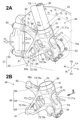
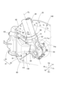
- 2A is a perspective view of a configuration in which a damper and a brake caliper are assembled to the axle bracket shown in FIG. 1
- FIG. 2B is a perspective view of the axle bracket alone shown in FIG. 2A.
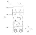
- FIG. 2B is a view of the connecting portion shown in FIG. 2B when viewed from the direction of arrow 3.
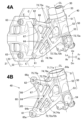
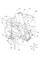
- 4A is a perspective view of a structure in which a damper and a brake caliper are assembled to the axle bracket shown in FIG. 2A, as viewed from the rear of the vehicle
- FIG. 4B is a perspective view of the axle bracket alone shown in FIG. 4A.
- FIG. 4A is a perspective view of a structure in which a damper and a brake caliper are assembled to the axle bracket shown in FIG. 2A, as viewed from the rear of the vehicle
- FIG. 4B is
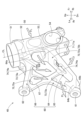
- FIG. 4B is a diagram in which a part of the axle bracket shown in FIG. 4B is omitted.
- FIG. 3 is a perspective view of a configuration in which a damper and a brake caliper are assembled to an axle bracket according to a second embodiment.
- FIG. 7 is a perspective view of a structure in which a damper and a brake caliper are assembled to an axle bracket according to a third embodiment.
- FIG. 4 is a perspective view of an axle bracket according to a fourth embodiment.
- 11A is a perspective view of an axle bracket according to Example 7, and FIG. 11B is a view of the axle bracket of FIG. 11A viewed from the direction of arrow 11B.
- left and right refers to the left and right with respect to a passenger riding in the saddle-ride type vehicle
- front and rear refers to front and rear with respect to the traveling direction of the saddle-ride type vehicle.
- Up indicates the top
- Dn indicates the bottom
- Fr indicates the front (direction of travel)
- Rr indicates the rear (direction opposite to the direction of travel)
- Li indicates the left
- Ri indicates the right.
- Example 1 Referring to FIGS. 1 to 5, an axle bracket 40 according to a first embodiment and a front fork 13 for a saddle type vehicle equipped with the same will be described.
- the front fork 13 is employed in a vehicle, for example, and is used in a motorcycle 10, which is a type of saddle-riding vehicle on which a rider rides astride.
- the motorcycle 10 may be referred to as a "saddle-type vehicle 10" or a "vehicle 10.”
- a motorcycle 10 which is a type of saddle-ride vehicle, includes a vehicle body 11, an engine 12 provided at the lower center of the vehicle body 11, and a front fork 13 provided at the front of the vehicle body 11. , a front wheel 14 supported by a front fork 13 , and a steering handle 15 connected to the front fork 13 .
- the motorcycle 10 includes a wheel support mechanism 16 that extends rearward from the rear of the vehicle body 11 and is swingable in the vertical direction, a rear wheel 17 supported by the wheel support mechanism 16, and a rear wheel 17 that extends between the vehicle body 11 and the wheel support mechanism 16.
- the vehicle includes a rear suspension (not shown) spanning between the vehicle body 11 and a passenger seat 18 provided at the center of the upper part of the vehicle body 11.
- the motorcycle 10 includes a brake 21 (wheel brake 21) that can brake the front wheel 14.
- the brake 21 is, for example, a disc brake, and includes a rotating brake disc 22 (brake disc rotor 22) fixed to the front wheel 14 and a fixed brake caliper 23.
- brake pressure generated from the master cylinder 25 is applied to the brake caliper 23, thereby applying brake pressure to the brake disc 22.
- the brake caliper 23 brakes the rotation of the front wheel 14 by pinching the brake disc 22.
- the front fork 13 includes two dampers 30 (buffer main bodies 30) provided on both sides of the front wheel 14.
- This damper 30 is, for example, an inverted damper configured by a combination of an upper outer tube 31 supported by the vehicle body 11 and a lower inner tube 32 supporting the front wheel 14.
- a lower end 33 of the damper 30 (lower end 33 of the inner tube 32) is connected to the axle 14a of the front wheel 14 by an axle bracket 40.
- the axle bracket 40 (axle holder 40) will be explained in detail.
- the axle bracket 40 includes a connecting portion 50 that connects the damper 30 to the axle 14a, and a connecting portion 50 that is provided on the rear side of the vehicle 10 (see FIG. 1).
- a brake mounting portion 60 is provided.
- the connecting portion 50 and the brake mounting portion 60 are configured as an integrally formed product or a combination of separate members.
- the connecting portion 50 includes a damper support portion 51 at the upper end that supports the lower end portion 33 of the damper 30, a brake support portion 52 integrally provided at the lower end of the damper support portion 51, and a brake support portion 52 at the lower end of the brake support portion 52.
- the axle support part 53 is integrally formed with the axle support part 53.
- the damper support portion 51, the brake support portion 52, and the axle support portion 53 are arranged on the center line CL of the damper 30, for example.
- the axle support portion 53 may be configured to be offset with respect to the center line CL of the damper 30.
- the damper support portion 51 is, for example, a bottomed cylindrical portion with an open top, and is capable of fitting and fixing the lower end portion 33 of the damper 30.
- the brake support portion 52 is a rod-shaped portion extending on the center line CL of the damper 30.
- the axle support portion 53 has a support hole 54 into which the axle 14a of the front wheel 14 (see FIG. 1) can be fitted and supported.
- the brake mounting portion 60 has a V-shaped configuration that opens vertically from the connecting portion 50 toward the rear of the vehicle 10, and has a lower mounting portion 61 and an upper mounting portion 62 at the rear end.
- the brake caliper 23 of the brake 21 can be attached to the lower attachment part 61 and the upper attachment part 62 using a fastening member 63 such as a bolt.
- This brake attachment part 60 is a lower arm that connects the left and right side arms 64, 64 extending from the brake support part 52, that is, from the coupling part 50 to the rear of the vehicle 10, and the lower ends of the left and right side arms 64, 64. 65, and an upper arm 66 extending from the connecting portion 50 to the rear of the vehicle 10.
- the left and right side arms 64, 64 are configured to taper downward from the rear of the vehicle 10 from the connecting portion 50. ing. That is, the base ends 64a, 64a of the left and right side arms 64, 64 are provided in the connecting portion 50 with a space between them. The rear ends 64b, 64b of the left and right side arms 64, 64 are connected to each other. Further, the left and right side arms 64, 64 are vertical plate-shaped portions, and are configured to taper downward from the connecting portion 50 toward the rear of the vehicle 10 when viewed from the side.
- the lower arm 65 is a horizontal plate-shaped portion that extends from the connecting portion 50 toward the rear of the vehicle 10 and forms the bottom plate of the brake mounting portion 60.
- the lower ends of the left and right side arms 64, 64 and the lower arm 65 are all integrally connected. It is integrally connected to the rear ends 64b, 64b of the left and right side arms 64, 64 and the rear end 65a of the lower arm 65, and is provided with the above-mentioned lower mounting portion 61.
- the upper arm 66 has a horizontal plate shape extending rearward and upward of the vehicle 10 from the base of the connecting portion 50 and the base ends 64a, 64a of the left and right side arms 64, 64.
- the above-described upper mounting portion 62 is provided at the rear end 66a of the upper arm 66.
- the longitudinal center portion of the left side arm 64 and the rear end 66a of the upper arm 66 support each other by a stay 67.
- the axle bracket 40 has an introduction part 71 (first introduction part 71) at least in the connecting part 50 that can guide fluid FL such as running wind or rainwater in the longitudinal direction of the vehicle 10 when the vehicle 10 is running. ing.
- This first introduction part 71 is preferably provided in the brake support part 52.
- the first introducing portion 71 has a through hole 71a (first through hole 71a) that penetrates the connecting portion 50 in the longitudinal direction of the vehicle 10.
- This first through hole 71a is located on the center line CL of the damper 30.
- the cross-sectional area of the first through hole 71a is preferably as large as possible in order to ensure the steering stability required of the axle bracket 40 and to reduce passage resistance of the fluid FL.
- the height and width of the first through hole 71a are set to be as large as the limit of the brake support portion 52.
- the brake attachment part 60 has an introduction part 72 (second introduction part 72) that can guide the fluid FL in the longitudinal direction of the vehicle 10.
- the second introduction portion 72 has a through hole 72a (second through hole 72a) that penetrates the brake mounting portion 60 in the longitudinal direction of the vehicle 10.
- the brake mounting portion 60 has a space 72b surrounded by left and right side arms 64, 64, a lower arm 65, and an upper arm 66.
- This space portion 72b communicates with the first through hole 71a of the connecting portion 50.
- the space 72b is open to the rear. Therefore, this space portion 72b penetrates the brake mounting portion 60 in the longitudinal direction of the vehicle 10, and forms a second through hole 72a.
- the brake attachment part 60 has an introduction part 73 (third introduction part 73) that can guide the fluid FL in the left-right direction of the vehicle 10 with respect to the brake attachment part 60.
- the third introduction portion 73 has a plurality of through holes 73a (third through holes 73a) that penetrate the brake mounting portion 60 in the left-right direction of the vehicle 10. More specifically, the plurality of third through holes 73a communicate with the second through hole 72a by passing through the left and right side arms 64, 64.
- the fluid FL introduced from the third through hole 73a to the second through hole 72a when the vehicle 10 is traveling. can be guided to the brake caliper 23 and the brake disc 22 through the second through hole 72a.
- the temperatures of the brake caliper 23 and the brake disc 22 can be lowered more efficiently.
- the brake attachment part 60 has an introduction part 74 (fourth introduction part 74) that can guide the fluid FL in the vertical direction of the vehicle 10 to the brake attachment part 60.
- the fourth introduction portion 74 has a through hole 74a (fourth through hole 74a) that penetrates the brake mounting portion 60 in the vertical direction of the vehicle 10. More specifically, the fourth through hole 74a communicates with the second through hole 72a by passing through the lower arm 65 and the upper arm 66.
- the fluid FL introduced from the fourth through hole 74a to the second through hole 72a when the vehicle 10 is traveling. can be guided to the brake caliper 23 and the brake disc 22 through the second through hole 72a.
- the temperatures of the brake caliper 23 and the brake disc 22 can be lowered more efficiently.
- the longitudinal center portion of the left side arm 64 and the longitudinal center portion of the upper arm 66 are supported by the bar-shaped stay 67.
- the through hole 75a surrounded by the left side arm 64, the upper arm 66, and the stay 67 is referred to as a fifth through hole 75a.
- the fifth through hole 75a penetrates the brake mounting portion 60 in the left-right direction of the vehicle 10 and communicates with the second through hole 72a.
- the brake mounting portion 60 has an introduction portion 75 (fifth introduction portion 75) that can guide the fluid FL in the left-right direction of the vehicle 10 with respect to the brake mounting portion 60.
- the fifth introduction portion 75 has a fifth through hole 75a that penetrates the brake mounting portion 60 in the left-right direction of the vehicle 10.
- the cooling effect of the brake 21 by the fluid FL such as running wind or rainwater in the longitudinal direction of the vehicle 10 when the vehicle 10 is running.
- the fluid FL introduced from the first introduction section 71 passes through the second introduction section 72 and flows rearward to cool the brake caliper 23 and the brake disc 22.
- the fluid FL introduced into the second through hole 72a from the third through hole 73a, the fourth through hole 74a, and the fifth through hole 75a is transferred from the second through hole 72a to the brake caliper 23 and the like. It flows to the brake disc 22 and cools it.
- Example 1 The description of Example 1 above is summarized as follows.
- the axle bracket 40 includes a connecting portion 50 that connects the damper 30 to the axle 14a, and a brake mounting portion 60 that is provided on the rear side of the vehicle 10 with respect to the connecting portion 50 and to which the brake 21 (brake caliper 23) can be attached. , is equipped with.
- At least the connecting portion 50 has a first introduction portion 71 that can introduce fluid in the longitudinal direction of the vehicle 10. In other words, the first introducing section 71 is provided so that the fluid FL is not blocked by the connecting section 50.
- the brake 21 can be efficiently cooled in the axle bracket 40 that includes the connecting portion 50 that connects the damper 30 to the axle 14a and the brake mounting portion 60 to which the brake 21 (brake caliper 23) can be attached. can. Moreover, a sufficient brake cooling effect can be obtained without providing an air duct around the axle bracket 40.
- the first introducing portion 71 has a first through hole 71a that penetrates the connecting portion 50 in the longitudinal direction of the vehicle 10. Therefore, the first introducing section 71 has a simple structure, which only has the through hole 71a in the connecting section 50. It is possible to easily achieve both the strength and weight reduction of the axle bracket 40 and the cooling of the brake 21.
- the brake attachment part 60 has a second introduction part 72 that can guide the fluid FL in the longitudinal direction of the vehicle 10. Therefore, even though the brake mounting part 60 that blocks the flow of the fluid FL is located behind the connecting part 50, the fluid FL introduced from the first introduction part 71 is passed through the second introduction part 72 to the brake 21. can be flowed efficiently. Therefore, the brake 21 can be efficiently cooled. Moreover, the appearance of the axle bracket 40 can be improved.
- the second introduction part 72 has a second through hole 72a that penetrates the brake mounting part 60 in the longitudinal direction of the vehicle 10. Therefore, the second introduction section 72 can have a simple configuration including only the second through hole 72a.
- the brake mounting portion 60 has a third through hole 73a (third introduction portion 73) that penetrates the brake mounting portion 60 in the left-right direction of the vehicle 10.
- This third through hole 73a communicates with the second through hole 72a. Therefore, the fluid FL can be introduced more efficiently.
- the front fork 13 for a saddle-ride type vehicle includes an axle bracket 40 having at least a first introduction portion 71. Therefore, the brake 21 can be cooled only by the axle bracket 40 without providing a cooling member such as an air duct around the axle bracket 40. Moreover, since there is no need to provide another cooling member, the degree of freedom in designing the front fork 13 for a saddle-ride type vehicle can be increased, and the appearance of the front fork 13 can be improved.
- axle brackets 140 to 640 of other embodiments will be described.
- the basic configurations of the axle brackets 140 to 640 of the other embodiments are the same as the axle bracket 40 of the first embodiment.
- reference numerals are used and detailed explanations are omitted.
- FIG. 6 is a perspective view illustrating the axle bracket 140 of the second embodiment, and corresponds to FIG. 2A illustrating the axle bracket 40 of the first embodiment.
- the axle bracket 140 is characterized in that it includes a cover 141 that covers the side surface of the brake mounting portion 60.
- This cover 141 preferably covers the entirety or a portion of at least one side surface of the brake mounting portion 60, for example, the entire side surface opposite to the brake disc 22.
- This cover 141 is removably attached to the brake attachment portion 60 using a fastening member 142 such as a screw.
- a fastening member 142 such as a screw.
- FIG. 7 is a perspective view illustrating the axle bracket 240 of the third embodiment, and corresponds to FIG. 6 illustrating the axle bracket 140 of the second embodiment.
- the cover 241 includes at least one (for example, a plurality of) guide fins 242 that can guide the fluid FL flowing along the cover 241 from the front to the rear and upward of the vehicle 10. It is characterized by the presence of The structure of the cover 241 itself is the same as the structure of the cover 141 of the second embodiment.
- the plurality of guide fins 242 are plate-shaped members whose plate surfaces face in the vertical direction, and extend outward in the vehicle width direction from the outer surface of the cover 241. Further, the plurality of guide fins 242 are arranged at regular intervals in the vertical direction with respect to the outer surface of the cover 241, and are provided integrally with the cover 241 or as separate members.
- These guide fins 242 are provided so as to slope upward from the front side of the cover 241 toward the rear. Therefore, the running wind FL (fluid FL) generated while the motorcycle 10 is running is guided by the guide fins 242 and flows rearward and upward. As a result, downforce fd can be applied to the front portion of the vehicle body 11. For example, even when the motorcycle 10 is accelerating, a stable feeling of ground contact can be obtained at the front part of the vehicle body 11, and the steering stability can be improved.
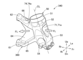
- FIG. 8 is a perspective view illustrating the axle bracket 340 of the fourth embodiment, and corresponds to FIG. 2B illustrating the axle bracket 40 of the first embodiment.
- the axle bracket 340 is characterized in that the side arm 64 (see FIGS. 2A and 2B) on the side opposite to the brake disc 22 in the brake mounting portion 360 is eliminated. Furthermore, the axle bracket 340 does not have the third introduction part 73 (see FIG. 2B) on the side arm 64 on the brake disc 22 side.
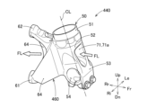
- Example 5 The axle bracket 440 of Example 5 will be described with reference to FIG. 9.
- FIG. 9 is a perspective view illustrating the axle bracket 440 of the fifth embodiment, and corresponds to FIG. 2B illustrating the axle bracket 40 of the first embodiment.
- the axle bracket 440 is characterized in that the left and right side arms 64 in the brake mounting part 460 do not have the third introduction part 73 (see FIG. 2B).
- Example 6 The axle bracket 540 of Example 6 will be described with reference to FIGS. 10A and 10B.
- FIG. 10A is a perspective view illustrating the axle bracket 540 of the sixth embodiment, and corresponds to FIG. 2B illustrating the axle bracket 40 of the first embodiment.
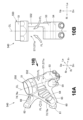
- FIG. 10B shows the axle bracket 540 of FIG. 10A viewed from the direction of arrow 10B.
- the axle bracket 540 is characterized by the configuration of the first introduction part 571 provided in the brake support part 552 of the connection part 550.
- This first introduction part 571 has a first through hole 571a cut out on the left or right side of the brake support part 552. That is, the first through hole 571a has a notch hole configuration, and corresponds to the first through hole 71a of Example 1 shown in FIG. 2A. Therefore, as shown in FIG. 10B, the brake support portion 552 has an L-shape when viewed from the front.
- Example 7 The axle bracket 640 of Example 7 will be described with reference to FIGS. 11A and 11B.
- FIG. 11A is a perspective view illustrating the axle bracket 640 of the seventh embodiment, and corresponds to FIG. 10A illustrating the axle bracket 540 of the sixth embodiment.
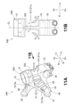
- FIG. 11B shows the axle bracket 640 of FIG. 11A viewed from the direction of arrow 11B.
- the axle bracket 640 is characterized by the configuration of two first introduction parts 671, 671 provided on the left and right sides of the brake support part 652 of the connection part 650. These first introduction parts 671, 671 have first through holes 671a, 671a cut out on both sides of the brake support part 652.
- the first through-holes 671a, 671a have a structure of notch holes, and correspond to the first through-hole 571a of the sixth embodiment shown in FIG. 10A. Therefore, as shown in FIG. 11B, the brake support portion 552 has an I-shape when viewed from the front.
- axle bracket 40, 140, 240, 340, 440, 540, 640 may be modified from the above embodiments as long as the functions and effects of the present invention are achieved. It is not limited.
- the brake 21 may be disposed on both sides of the front wheel 14.
- the axle brackets 40 to 640 of the present invention will be provided on the left and right dampers 30, 30 of the front fork 13.
- the brake 21 is not limited to the configuration of a disc brake, but may be of a drum brake configuration, for example.
- the connecting portions 50, 550, and 650 can be configured to include a suction duct that can suck in the fluid FL from the front of the vehicle 10. This suction duct communicates with the front portions of the first through holes 71a, 571a, and 671a.
- the front fender prefferably includes a fluid introduction part that can suck in the fluid FL from the front of the vehicle 10.
- This fluid introduction part is connected to the first through holes 71a, 571a, 671a of the connecting parts 50, 550, 650.
- axle brackets 40 to 640 of the present invention and the front fork 13 equipped with the axle brackets 40 to 640 are suitable for mounting on a saddle-ride type vehicle.
Landscapes
- Engineering & Computer Science (AREA)
- General Engineering & Computer Science (AREA)
- Mechanical Engineering (AREA)
- Braking Arrangements (AREA)
Abstract
アクスルブラケット(40)は、ダンパ(30)を車軸(14a)に連結する連結部(50)と、前記連結部(50)に対して車両(10)の後方側に設けられたブレーキ取付部(60)とを備えている。前記ブレーキ取付部(60)は、ブレーキ(21)を取り付け可能である。少なくとも前記連結部(50)は、車両(10)の前後方向に流体(FL)を導くことが可能な第1導入部(71)を有している。
Description
本発明は、特に乗員が跨がって乗車する鞍乗り型車両に採用するのに好適なアクスルブラケット及びフロントフォークに関する。
自動二輪車等の鞍乗り型車両は、前輪を操舵するフロントフォークにアクスルブラケットを備えている。このアクスルブラケットは、ダンパを車軸に連結する連結部と、ブレーキ(ブレーキキャリパ)を取り付け可能なブレーキ取付部と、を備えている。ブレーキは、制動時に発熱するので、走行風によって冷却する技術の開発が進められている。ブレーキを冷却する方式としては、一般にアクスルブラケットの周りにエアダクトを追加する方式が、採用されている。このようなエアダクトによりブレーキを冷却する技術は、例えば特許文献1及び特許文献2によって知られている。
特許文献1で知られているブレーキ冷却技術は、フロントフェンダの下方に有しているエアダクトと、フロントフォークの下方に有しているエアダクトとから、各々取り入れた走行風をブレーキディスク及びブレーキキャリパに吹き出すことによって、ブレーキを冷却するというものである。
特許文献2で知られているブレーキ冷却技術は、フロントフェンダの前端部に走行風取入口(エアダクトに相当)を設け、この走行風取入口から取り入れた走行風を、前輪のブレーキディスクへ走行風転向部によって導くというものである。
しかしながら、鞍乗り型車両の車種によっては、アクスルブラケットの周りにエアダクトを追加する方式を、制限される場合があり得る。ブレーキは、アクスルブラケットの後方に設けられているので、鞍乗り型車両の走行中に発生する走行風は、アクスルブラケットの影響を受ける。その場合であっても、ブレーキを効率よく冷却することが求められる。
本発明は、ダンパを車軸に連結する連結部と、ブレーキを取り付け可能なブレーキ取付部と、を備えたアクスルブラケットにおいて、ブレーキを効率よく冷却することができる技術を、提供することを課題とする。
本発明者は、鋭意検討の結果、ダンパを車軸に連結する連結部の後部には、ブレーキを取り付け可能なブレーキ取付部が設けられているので、鞍乗り型車両等の車両の走行中に発生する走行風などの流体の一部が、連結部によって遮られることに着目した。そして、車両の前後方向に流体を導くことが可能な導入部を、連結部に設けることによって、流体をブレーキに効率よく流すことが可能になることを知見した。本発明は、これらの知見に基づいて完成させた。
本開示によれば、ダンパを車軸に連結する連結部と、前記連結部に対して車両の後方側に設けられておりブレーキを取り付け可能なブレーキ取付部と、を備えたアクスルブラケットであって、少なくとも前記連結部は、前記車両の前後方向に流体を導くことが可能な第1導入部を有している、アクスルブラケットが提供される。
本開示では、ダンパを車軸に連結する連結部と、ブレーキを取り付け可能なブレーキ取付部と、を備えたアクスルブラケットにおいて、ブレーキを効率よく冷却することができる技術を、提供することができる。
本発明の実施の形態を添付図に基づいて以下に説明する。なお、添付図に示した形態は本発明の一例であり、本発明は当該形態に限定されない。説明中、左右とは鞍乗り型車両に乗車した乗員を基準として左右、前後とは鞍乗り型車両の進行方向を基準として前後を指す。また、図中Upは上、Dnは下を、Frは前(進行方向、走行方向)、Rrは後(進行方向に対して逆方向)、Liは左、Riは右を示している。
<実施例1>
図1~図5を参照しつつ、実施例1のアクスルブラケット40及びこれを備えた鞍乗り型車両用フロントフォーク13を説明する。
図1~図5を参照しつつ、実施例1のアクスルブラケット40及びこれを備えた鞍乗り型車両用フロントフォーク13を説明する。
図1に示されるように、フロントフォーク13は例えば乗り物に採用され、一例として、乗員が跨がって乗車する鞍乗り型車両の一種である自動二輪車10に用いられる。以下において、自動二輪車10を「鞍乗り型車両10」または「車両10」と称することがある。
図1に示されるように、鞍乗り型車両の一種である自動二輪車10は、車体11と、車体11の中央下部に設けられたエンジン12と、車体11の前部に設けられたフロントフォーク13と、フロントフォーク13に支持された前輪14と、フロントフォーク13に連結された操舵ハンドル15とを備えている。
さらに自動二輪車10は、車体11の後部から後方へ向かって延びて上下方向にスイング可能な車輪支持機構16と、この車輪支持機構16に支持された後輪17と、車体11と車輪支持機構16との間に架け渡されたリヤサスペンション(図示せず)と、車体11の上部中央に設けられた乗員用シート18とを備えている。
さらに自動二輪車10は、前輪14を制動可能なブレーキ21(車輪ブレーキ21)を備えている。このブレーキ21は、例えば、ディスクブレ-キの構成であって、前輪14に固定された回転側のブレーキディスク22(ブレーキディスクロータ22)と、固定側のブレーキキャリパ23とによって構成されている。操舵ハンドル15に設けられているブレーキレバー24の操作に応じて、マスタシリンダ25から発生されたブレーキ油圧が、ブレーキキャリパ23に付与されることによって、ブレーキディスク22にブレーキ圧を付与することができる。つまり、ブレーキキャリパ23がブレーキディスク22を挟みつけることによって前輪14の回転を制動する。
フロントフォーク13は、前輪14の両側にそれぞれ設けられた2つのダンパ30(緩衝器本体30)を備えている。このダンパ30は、例えば車体11に支持される上部のアウタチューブ31と、前輪14を支持する下部のインナチューブ32と、の組合せによって構成されている倒立型ダンパである。このダンパ30の下端部33(インナチューブ32の下端部33)は、アクスルブラケット40によって前輪14の車軸14aに連結されている。
以下、アクスルブラケット40(アクスルホルダ40)について詳しく説明する。図2A及び図2Bに示されるように、アクスルブラケット40は、ダンパ30を車軸14aに連結する連結部50と、この連結部50に対して車両10(図1参照)の後方側に設けられているブレーキ取付部60とを備えている。連結部50とブレーキ取付部60とは、一体形成品、または別々の部材の組合せ品によって構成されている。
図3も参照する。連結部50は、ダンパ30の下端部33を支持する上端のダンパ支持部51と、このダンパ支持部51の下端に一体に有しているブレーキ支持部52と、このブレーキ支持部52の下端に一体に有している車軸支持部53と、から成る。ダンパ支持部51とブレーキ支持部52と車軸支持部53とは、例えば、ダンパ30の中心線CL上に配列されている。車軸支持部53は、ダンパ30の中心線CLに対してオフセットした構成であってもよい。
ダンパ支持部51は、例えば上を開放した有底筒状の部分であって、ダンパ30の下端部33を嵌合し且つ固定することが可能である。ブレーキ支持部52は、ダンパ30の中心線CL上に延びている棒状の部分である。車軸支持部53は、前輪14(図1参照)の車軸14aを嵌合し且つ支持することが可能な支持孔54を有している。
図4A、図4B及び図5も参照する。ブレーキ取付部60は、連結部50から車両10の後方へ向かって、上下方向へ開くV字状の構成であって、後端に下取付部61と上取付部62とを有している。下取付部61と上取付部62とは、ブレーキ21のブレーキキャリパ23をボルト等の締結部材63によって取り付け可能である。
このブレーキ取付部60は、ブレーキ支持部52から、つまり連結部50から車両10の後方へ延びる左右のサイドアーム64,64と、左右のサイドアーム64,64の下端間を繋いでいる下側アーム65と、連結部50から車両10の後方へ延びる上側アーム66とから成る。
車軸支持部53を上から見て(ダンパ30の中心線CLに沿う方向から見て)、左右のサイドアーム64,64は、連結部50から車両10の後下方へ向かって先細り状に構成されている。つまり、左右のサイドアーム64,64の基端64a,64aは互いに間隔を有して連結部50に設けられている。左右のサイドアーム64,64の後端64b,64b同士は互いに繋がっている。さらに、左右のサイドアーム64,64は、縦板状の部分であって、側方から見て、連結部50から車両10の後下方へ向かって先細り状に構成されている。
下側アーム65は、連結部50から車両10の後方へ延びて、ブレーキ取付部60の底板を成す横板状の部分である。左右のサイドアーム64,64の下端と下側アーム65とは、全て一体的に繋がっている。左右のサイドアーム64,64の後端64b,64bと、下側アーム65の後端65aと一体的に繋がっており、上述の下取付部61が設けられている。
上側アーム66は、連結部50と左右のサイドアーム64,64の基端64a,64aとの付け根部分から、車両10の後上方へ向かって延びた横板状に構成されている。上側アーム66の後端66aには、上述の上取付部62が設けられている。左のサイドアーム64の長手方向中央部と、上側アーム66の後端66aとは、ステー67によって互いに支え合っている。
アクスルブラケット40は、少なくとも連結部50に、車両10の走行時にこの車両10の前後方向に走行風や雨水などの流体FLを導くことが可能な導入部71(第1導入部71)を有している。この第1導入部71は、ブレーキ支持部52に有していることが好ましい。
この第1導入部71は、連結部50に対して車両10の前後方向に貫通する貫通孔71a(第1貫通孔71a)を有している。この第1貫通孔71aは、ダンパ30の中心線CL上に位置している。この第1貫通孔71aの断面積は、アクスルブラケット40に求められる操縦安定性を確保しつつ、流体FLの通過抵抗を低減するためには、できるだけ大きいことが好ましい。例えば、この第1貫通孔71aの高さ及び幅は、ブレーキ支持部52の限界まで大きく設定される。
好ましくは、ブレーキ取付部60は、車両10の前後方向に流体FLを導くことが可能な導入部72(第2導入部72)を有している。この第2導入部72は、ブレーキ取付部60に対して車両10の前後方向に貫通する貫通孔72a(第2貫通孔72a)を有している。
詳しく述べると、ブレーキ取付部60は、左右のサイドアーム64,64と下側アーム65と上側アーム66とによって囲まれた空間部72bを有している。この空間部72bは、連結部50の第1貫通孔71aに連通している。しかも、左右のサイドアーム64,64に対して、上側アーム66の後部が上方へ離れているので、空間部72bは後方へ開放している。従って、この空間部72bは、ブレーキ取付部60に対して車両10の前後方向に貫通しており、第2貫通孔72aを構成する。
より好ましくは、ブレーキ取付部60は、このブレーキ取付部60に対して車両10の左右方向に流体FLを導くことが可能な導入部73(第3導入部73)を有している。この第3導入部73は、ブレーキ取付部60に対して車両10の左右方向に貫通する複数の貫通孔73a(第3貫通孔73a)を有している。より具体的には、この複数の第3貫通孔73aは、左右のサイドアーム64,64を貫通することによって、第2貫通孔72aと連通している。
左右方向に貫通する第3貫通孔73aを、前後方向に貫通する第2貫通孔72aと連通することによって、車両10の走行時に、第3貫通孔73aから第2貫通孔72aへ導入した流体FLを、この第2貫通孔72aからブレーキキャリパ23やブレーキディスク22へ導くことが可能である。この結果、ブレーキキャリパ23やブレーキディスク22の温度を、より効率よく下げることができる。
より好ましくは、ブレーキ取付部60は、このブレーキ取付部60に対して車両10の上下方向に流体FLを導くことが可能な導入部74(第4導入部74)を有している。この第4導入部74は、ブレーキ取付部60に対して車両10の上下方向に貫通する貫通孔74a(第4貫通孔74a)を有している。より具体的には、この第4貫通孔74aは、下側アーム65と上側アーム66とを貫通することによって、第2貫通孔72aと連通している。
上下方向に貫通する第4貫通孔74aを、前後方向に貫通する第2貫通孔72aと連通することによって、車両10の走行時に、第4貫通孔74aから第2貫通孔72aへ導入した流体FLを、この第2貫通孔72aからブレーキキャリパ23やブレーキディスク22へ導くことが可能である。この結果、ブレーキキャリパ23やブレーキディスク22の温度を、より効率よく下げることができる。
更には、上述のように、左のサイドアーム64の長手方向中央部と、上側アーム66の長手方向中央部とが、バー状のステー67によって支え合っている。左のサイドアーム64と上側アーム66とステー67とに囲まれた貫通孔75aのことを、第5貫通孔75aという。この第5貫通孔75aは、ブレーキ取付部60に対して車両10の左右方向に貫通するとともに、第2貫通孔72aと連通している。
以上の説明から明らかなように、ブレーキ取付部60は、このブレーキ取付部60に対して車両10の左右方向に流体FLを導くことが可能な導入部75(第5導入部75)を有する。この第5導入部75は、ブレーキ取付部60に対して車両10の左右方向に貫通する第5貫通孔75aを有している。
次に、車両10の走行時に、この車両10の前後方向に走行風や雨水などの流体FLによる、ブレーキ21の冷却作用について説明する。車両10の走行により、第1導入部71から導入された流体FLは、第2導入部72を通過して後方へ流れて、ブレーキキャリパ23やブレーキディスク22を冷却する。さらに、車両10の走行時に、第3貫通孔73a、第4貫通孔74a、第5貫通孔75aから第2貫通孔72aへ導入された流体FLは、この第2貫通孔72aからブレーキキャリパ23やブレーキディスク22へ流れて冷却する。
上記実施例1の説明をまとめると、次のとおりである。
アクスルブラケット40は、ダンパ30を車軸14aに連結する連結部50と、連結部50に対して車両10の後方側に設けられておりブレーキ21(ブレーキキャリパ23)を取り付け可能なブレーキ取付部60と、を備えている。少なくとも連結部50は、車両10の前後方向に流体を導くことが可能な第1導入部71を有している。つまり、流体FLが連結部50によって遮られないように、第1導入部71を設けた。
このため、鞍乗り型車両など車両10の走行中に発生する走行風などの流体FLの一部を、第1導入部71から導入して、流体FLをブレーキ21に直接に効率よく流すことができるる。この結果、ダンパ30を車軸14aに連結する連結部50と、ブレーキ21(ブレーキキャリパ23)を取り付け可能なブレーキ取付部60と、を備えたアクスルブラケット40において、ブレーキ21を効率よく冷却することができる。しかも、アクスルブラケット40の周りにエアダクトを設けることなく、十分なブレーキ冷却効果を得ることができる。
さらには、第1導入部71は、連結部50に対して車両10の前後方向に貫通する第1貫通孔71aを有している。このため、第1導入部71は、連結部50に貫通孔71aを有するだけの、簡単な構成である。アクスルブラケット40の強度の確保及び軽量化と、ブレーキ21の冷却との、両立を容易に図ることができる。
さらには、ブレーキ取付部60は、車両10の前後方向に流体FLを導くことが可能な第2導入部72を有している。このため、連結部50の後方に、流体FLの流れを妨げるブレーキ取付部60が位置しているにもかかわらず、第1導入部71から導入した流体FLを、第2導入部72を通してブレーキ21に効率よく流すことができる。従って、ブレーキ21を効率よく冷却することができる。しかも、アクスルブラケット40の外観性を向上を図ることができる。
さらには、第2導入部72は、ブレーキ取付部60に対して車両10の前後方向に貫通する第2貫通孔72aを有している。このため、第2導入部72を、第2貫通孔72aのみの簡単な構成とすることができる。
さらには、ブレーキ取付部60は、このブレーキ取付部60に対して車両10の左右方向に貫通する第3貫通孔73a(第3導入部73)を有している。この第3貫通孔73aは、第2貫通孔72aと連通している。このため、流体FLをより効率よく導入することができる。
さらには、鞍乗り型車両用フロントフォーク13は、少なくとも第1導入部71を有したアクスルブラケット40を備えている。このため、アクスルブラケット40の周りにエアダクト等の冷却用部材を設けることなく、アクスルブラケット40のみによって、ブレーキ21を冷却することができる。しかも、他の冷却用部材を設ける必要がないので、鞍乗り型車両用フロントフォーク13の設計の自由度を高めるとともに、このフロントフォーク13の外観性の向上を図ることができる。
次に、他の実施例のアクスルブラケット140~640について説明する。他の実施例のアクスルブラケット140~640の基本的な構成は、実施例1のアクスルブラケット40と共通する。上記アクスルブラケット40と共通する部分については、符号を流用すると共に、詳細な説明を省略する。
<実施例2>
図6を参照しつつ、実施例2のアクスルブラケット140を説明する。
図6を参照しつつ、実施例2のアクスルブラケット140を説明する。
図6は、実施例2のアクスルブラケット140を説明する斜視図であって、上記実施例1のアクスルブラケット40を説明する図2Aに対応している。アクスルブラケット140は、ブレーキ取付部60の側面を覆うカバー141を備えていることを特徴とする。
このカバー141は、ブレーキ取付部60の少なくとも一方の側面の全体又は一部、例えばブレーキディスク22とは反対側の側面全体を覆うことが好ましい。このカバー141は、ブレーキ取付部60に対し、ビス等の締結部材142によって取り外し可能に取り付けられる。カバー141を備えることによって、第1導入部71から導入した流体FLが車幅方向外側へ拡散しないように規制し、より積極的に効率よくブレーキ21(ブレーキキャリパ23)へ流すことができる。この結果、ブレーキ21を効率よく冷却することができる。
<実施例3>
図7を参照しつつ、実施例3のアクスルブラケット240を説明する。
図7を参照しつつ、実施例3のアクスルブラケット240を説明する。
図7は、実施例3のアクスルブラケット240を説明する斜視図であって、上記実施例2のアクスルブラケット140を説明する図6に対応している。実施例3のアクスルブラケット240では、カバー241は、このカバー241に沿って流れる流体FLを車両10の前方から後上方へ導くことが可能な少なくとも1つ(例えば複数)の誘導フィン242を備えていることを特徴とする。カバー241自体の構成は、実施例2のカバー141の構成と同じである。
複数の誘導フィン242は、板面が上下方向を向いた板状の部材であって、カバー241の外面から車幅方向外側へ延びている。さらに、複数の誘導フィン242は、カバー241の外面に対して上下方向に一定の間隔で配列されており、カバー241に一体または別部材として設けられている。
これらの誘導フィン242は、カバー241の前側から後方へ向かって上がり傾斜に設けられている。このため、自動二輪車10の走行中に発生した走行風FL(流体FL)は、誘導フィン242に案内されて後上方へ流れる。この結果、車体11の前部に対して、ダウンフォースfdを付加することができる。例えば、自動二輪車10の加速時であっても、車体11の前部に安定した接地感を得ることができ、操縦安定性の向上を図ることができる。
<実施例4>
図8を参照しつつ、実施例4のアクスルブラケット340を説明する。
図8を参照しつつ、実施例4のアクスルブラケット340を説明する。
図8は、実施例4のアクスルブラケット340を説明する斜視図であって、上記実施例1のアクスルブラケット40を説明する図2Bに対応している。アクスルブラケット340は、ブレーキ取付部360のなかの、ブレーキディスク22とは反対側のサイドアーム64(図2A及び図2B参照)を廃止したことを特徴とする。さらに、アクスルブラケット340は、ブレーキディスク22側のサイドアーム64に第3導入部73(図2B参照)を有していない。
<実施例5>
図9を参照しつつ、実施例5のアクスルブラケット440を説明する。
図9を参照しつつ、実施例5のアクスルブラケット440を説明する。
図9は、実施例5のアクスルブラケット440を説明する斜視図であって、上記実施例1のアクスルブラケット40を説明する図2Bに対応している。アクスルブラケット440は、ブレーキ取付部460のなかの、左右のサイドアーム64に第3導入部73(図2B参照)を有していないことを特徴とする。
<実施例6>
図10A及び図10Bを参照しつつ、実施例6のアクスルブラケット540を説明する。
図10A及び図10Bを参照しつつ、実施例6のアクスルブラケット540を説明する。
図10Aは、実施例6のアクスルブラケット540を説明する斜視図であって、上記実施例1のアクスルブラケット40を説明する図2Bに対応している。図10Bは、図10Aのアクスルブラケット540を10B矢視方向から見ている。
アクスルブラケット540は、連結部550のブレーキ支持部552に有している第1導入部571の構成に特徴がある。この第1導入部571は、ブレーキ支持部552の左または右の側方を切り欠いた第1貫通孔571aを有している。つまり、第1貫通孔571aは、切り欠き孔の構成であって、図2Aに示される実施例1の第1貫通孔71aに対応している。このため、図10Bに示されるように、ブレーキ支持部552は、正面視L字状を呈している。
<実施例7>
図11A及び図11Bを参照しつつ、実施例7のアクスルブラケット640を説明する。
図11A及び図11Bを参照しつつ、実施例7のアクスルブラケット640を説明する。
図11Aは、実施例7のアクスルブラケット640を説明する斜視図であって、上記実施例6のアクスルブラケット540を説明する図10Aに対応している。図11Bは、図11Aのアクスルブラケット640を11B矢視方向から見ている。
アクスルブラケット640は、連結部650のブレーキ支持部652の左右に有している2つの第1導入部671,671の構成に特徴がある。これらの第1導入部671,671は、ブレーキ支持部652の両側を切り欠いた第1貫通孔671a,671aを有している。つまり、第1貫通孔671a,671aは、切り欠き孔の構成であって、図10Aに示される実施例6の第1貫通孔571aに対応している。このため、図11Bに示されるように、ブレーキ支持部552は、正面視I字状を呈している。
なお、本発明によるアクスルブラケット40,140,240,340,440,540,640及びこれを備えた鞍乗り型車両用フロントフォーク13は、本発明の作用及び効果を奏する限りにおいて、上記実施例に限定されるものではない。
例えば、車両10は前輪14の片側にのみブレーキ21を配置した例を説明したが、前輪14の両側にブレーキ21を配置した構成であってもよい。その場合には、フロントフォーク13の左右のダンパ30,30に、本発明のアクスルブラケット40~640を設けることになる。
また、ブレーキ21は、ディスクブレ-キの構成に限定されるものではなく、例えばドラムブレーキの構成であってもよい。
また、連結部50,550,650は、車両10の前方から流体FLを吸入可能な吸入ダクトを備えた構成とすることが可能である。この吸入ダクトは、第1貫通孔71a,571a,671aの前部に連通することになる。
また、フロントフェンダに、車両10の前方から流体FLを吸入可能な流体導入部を備えた構成とすることが可能である。この流体導入部は、連結部50,550,650の第1貫通孔71a,571a,671aに接続される。
本発明のアクスルブラケット40~640及びこのアクスルブラケット40~640を備えたフロントフォーク13は、鞍乗り型車両用に搭載するのに好適である。
10 鞍乗り型車両
13 フロントフォーク
14 前輪
14a 車軸
21 ブレーキ
22 ブレーキディスク
23 ブレーキキャリパ
30 ダンパ
40,140,240,340,440,540,640 アクスルブラケット
50,550,650 連結部
52,552,652 ブレーキ支持部
60,360,460 ブレーキ取付部
71,571,671 第1導入部
71a,571a,671a 第1貫通孔
72 第2導入部
72a 第2貫通孔
141,241 カバー
242 誘導フィン
FL 流体
13 フロントフォーク
14 前輪
14a 車軸
21 ブレーキ
22 ブレーキディスク
23 ブレーキキャリパ
30 ダンパ
40,140,240,340,440,540,640 アクスルブラケット
50,550,650 連結部
52,552,652 ブレーキ支持部
60,360,460 ブレーキ取付部
71,571,671 第1導入部
71a,571a,671a 第1貫通孔
72 第2導入部
72a 第2貫通孔
141,241 カバー
242 誘導フィン
FL 流体
Claims (7)
- ダンパを車軸に連結する連結部と、前記連結部に対して車両の後方側に設けられておりブレーキを取り付け可能なブレーキ取付部と、を備えたアクスルブラケットであって、
少なくとも前記連結部は、前記車両の前後方向に流体を導くことが可能な第1導入部を有している、アクスルブラケット。 - 前記第1導入部は、前記連結部に対して前記車両の前後方向に貫通する第1貫通孔を有している、請求項1に記載のアクスルブラケット。
- 前記ブレーキ取付部は、前記車両の前後方向に前記流体を導くことが可能な第2導入部を有している、請求項1または請求項2に記載のアクスルブラケット。
- 前記第2導入部は、前記ブレーキ取付部に対して前記車両の前後方向に貫通する第2貫通孔を有している、請求項3に記載のアクスルブラケット。
- 前記ブレーキ取付部の側面を覆うカバーを、更に備えている、請求項1~4のいずれか1項に記載のアクスルブラケット。
- 前記カバーは、前記カバーに沿って流れる流体を、前記車両の前方から後上方へ導くことが可能な誘導フィンを備えている、請求項5に記載のアクスルブラケット。
- 請求項1~6のいずれか1項のアクスルブラケットを備えた、鞍乗り型車両用フロントフォーク。
Priority Applications (4)
| Application Number | Priority Date | Filing Date | Title |
|---|---|---|---|
| US18/848,003 US20250043838A1 (en) | 2022-03-18 | 2023-03-10 | Axle bracket and front fork for saddle-riding vehicle provided with same |
| PCT/JP2023/009194 WO2023176706A1 (ja) | 2022-03-18 | 2023-03-10 | アクスルブラケット及びこれを備えた鞍乗り型車両用フロントフォーク |
| DE112023001538.4T DE112023001538T5 (de) | 2022-03-18 | 2023-03-10 | Achshalterung und vordergabel für ein damit ausgestattetes sattelfahrzeug |
| JP2023516097A JP7296024B1 (ja) | 2022-03-18 | 2023-03-10 | アクスルブラケット及びこれを備えた鞍乗り型車両用フロントフォーク |
Applications Claiming Priority (2)
| Application Number | Priority Date | Filing Date | Title |
|---|---|---|---|
| JP2022043319 | 2022-03-18 | ||
| JP2022-043319 | 2022-03-18 |
Publications (1)
| Publication Number | Publication Date |
|---|---|
| WO2023175997A1 true WO2023175997A1 (ja) | 2023-09-21 |
Family
ID=88023057
Family Applications (1)
| Application Number | Title | Priority Date | Filing Date |
|---|---|---|---|
| PCT/JP2022/020158 Ceased WO2023175997A1 (ja) | 2022-03-18 | 2022-05-13 | アクスルブラケット及びこれを備えた鞍乗り型車両用フロントフォーク |
Country Status (1)
| Country | Link |
|---|---|
| WO (1) | WO2023175997A1 (ja) |
Citations (8)
| Publication number | Priority date | Publication date | Assignee | Title |
|---|---|---|---|---|
| JPS5347246U (ja) * | 1976-09-25 | 1978-04-21 | ||
| JPS6159192U (ja) * | 1984-09-11 | 1986-04-21 | ||
| JPS63105597U (ja) * | 1986-12-26 | 1988-07-08 | ||
| JPH027086U (ja) * | 1988-06-24 | 1990-01-17 | ||
| JPH047740U (ja) * | 1990-05-09 | 1992-01-23 | ||
| JPH04113294U (ja) * | 1991-03-25 | 1992-10-02 | スズキ株式会社 | 自動2輪車のデイスクブレーキカバー |
| JP2011057113A (ja) * | 2009-09-11 | 2011-03-24 | Yamaha Motor Co Ltd | 自動二輪車 |
| JP2017217947A (ja) * | 2016-06-03 | 2017-12-14 | 川崎重工業株式会社 | 自動二輪車及びそのダウンフォース発生装置 |
-
2022
- 2022-05-13 WO PCT/JP2022/020158 patent/WO2023175997A1/ja not_active Ceased
Patent Citations (8)
| Publication number | Priority date | Publication date | Assignee | Title |
|---|---|---|---|---|
| JPS5347246U (ja) * | 1976-09-25 | 1978-04-21 | ||
| JPS6159192U (ja) * | 1984-09-11 | 1986-04-21 | ||
| JPS63105597U (ja) * | 1986-12-26 | 1988-07-08 | ||
| JPH027086U (ja) * | 1988-06-24 | 1990-01-17 | ||
| JPH047740U (ja) * | 1990-05-09 | 1992-01-23 | ||
| JPH04113294U (ja) * | 1991-03-25 | 1992-10-02 | スズキ株式会社 | 自動2輪車のデイスクブレーキカバー |
| JP2011057113A (ja) * | 2009-09-11 | 2011-03-24 | Yamaha Motor Co Ltd | 自動二輪車 |
| JP2017217947A (ja) * | 2016-06-03 | 2017-12-14 | 川崎重工業株式会社 | 自動二輪車及びそのダウンフォース発生装置 |
Similar Documents
| Publication | Publication Date | Title |
|---|---|---|
| JP7296024B1 (ja) | アクスルブラケット及びこれを備えた鞍乗り型車両用フロントフォーク | |
| JP6225401B2 (ja) | 鞍乗り型車両 | |
| JP2004082850A (ja) | 自動二輪車等車両におけるリンク式フロントサスペンション装置 | |
| CN110015368B (zh) | 鞍座式骑乘车辆 | |
| CN101219690B (zh) | 二轮机动车 | |
| CN203439188U (zh) | 跨骑式车辆 | |
| JP2011111002A (ja) | 電動式不整地走行車 | |
| EP3135571B1 (en) | Straddle type vehicle | |
| JP5414331B2 (ja) | 鞍乗り型車両 | |
| EP3141464B1 (en) | Rear fender for motorcycle | |
| CN100465049C (zh) | 跨乘式车辆 | |
| JP5118575B2 (ja) | 自動二輪車 | |
| WO2018225199A1 (ja) | 鞍乗り型車両 | |
| JP2012017085A (ja) | 鞍乗型車両 | |
| JP2005082024A (ja) | ブレーキホースの支持構造 | |
| CN101472787A (zh) | 骑跨型轮式车辆及其框架 | |
| JP2015085844A (ja) | 鞍乗型車両 | |
| JP7148486B2 (ja) | 鞍乗り型車両 | |
| JP7148487B2 (ja) | 鞍乗り型車両 | |
| CN114981100A (zh) | 用于车辆的前悬架组件 | |
| CN112776929B (zh) | 车辆摆臂 | |
| EP3533698B1 (en) | Brake caliper cooling structure | |
| JP2024051985A (ja) | 車両用部品、及び車両 | |
| JP6855276B2 (ja) | 鞍乗り型車両の車体フレーム構造 | |
| JP2024114504A (ja) | 鞍乗り型車両 |
Legal Events
| Date | Code | Title | Description |
|---|---|---|---|
| 121 | Ep: the epo has been informed by wipo that ep was designated in this application |
Ref document number: 22932263 Country of ref document: EP Kind code of ref document: A1 |
|
| NENP | Non-entry into the national phase |
Ref country code: DE |
|
| 122 | Ep: pct application non-entry in european phase |
Ref document number: 22932263 Country of ref document: EP Kind code of ref document: A1 |