WO2023175961A1 - 光ファイバケーブル - Google Patents
光ファイバケーブル Download PDFInfo
- Publication number
- WO2023175961A1 WO2023175961A1 PCT/JP2022/012824 JP2022012824W WO2023175961A1 WO 2023175961 A1 WO2023175961 A1 WO 2023175961A1 JP 2022012824 W JP2022012824 W JP 2022012824W WO 2023175961 A1 WO2023175961 A1 WO 2023175961A1
- Authority
- WO
- WIPO (PCT)
- Prior art keywords
- optical fiber
- cable
- fiber cable
- core
- jacket
- Prior art date
- Legal status (The legal status is an assumption and is not a legal conclusion. Google has not performed a legal analysis and makes no representation as to the accuracy of the status listed.)
- Ceased
Links
Images


Classifications
-
- G—PHYSICS
- G02—OPTICS
- G02B—OPTICAL ELEMENTS, SYSTEMS OR APPARATUS
- G02B6/00—Light guides; Structural details of arrangements comprising light guides and other optical elements, e.g. couplings
- G02B6/44—Mechanical structures for providing tensile strength and external protection for fibres, e.g. optical transmission cables
- G02B6/4401—Optical cables
- G02B6/441—Optical cables built up from sub-bundles
-
- G—PHYSICS
- G02—OPTICS
- G02B—OPTICAL ELEMENTS, SYSTEMS OR APPARATUS
- G02B6/00—Light guides; Structural details of arrangements comprising light guides and other optical elements, e.g. couplings
- G02B6/44—Mechanical structures for providing tensile strength and external protection for fibres, e.g. optical transmission cables
- G02B6/4401—Optical cables
- G02B6/4429—Means specially adapted for strengthening or protecting the cables
-
- G—PHYSICS
- G02—OPTICS
- G02B—OPTICAL ELEMENTS, SYSTEMS OR APPARATUS
- G02B6/00—Light guides; Structural details of arrangements comprising light guides and other optical elements, e.g. couplings
- G02B6/44—Mechanical structures for providing tensile strength and external protection for fibres, e.g. optical transmission cables
- G02B6/4401—Optical cables
- G02B6/4429—Means specially adapted for strengthening or protecting the cables
- G02B6/443—Protective covering
- G02B6/4432—Protective covering with fibre reinforcements
-
- G—PHYSICS
- G02—OPTICS
- G02B—OPTICAL ELEMENTS, SYSTEMS OR APPARATUS
- G02B6/00—Light guides; Structural details of arrangements comprising light guides and other optical elements, e.g. couplings
- G02B6/44—Mechanical structures for providing tensile strength and external protection for fibres, e.g. optical transmission cables
- G02B6/4401—Optical cables
- G02B6/4429—Means specially adapted for strengthening or protecting the cables
- G02B6/4436—Heat resistant
-
- G—PHYSICS
- G02—OPTICS
- G02B—OPTICAL ELEMENTS, SYSTEMS OR APPARATUS
- G02B6/00—Light guides; Structural details of arrangements comprising light guides and other optical elements, e.g. couplings
- G02B6/44—Mechanical structures for providing tensile strength and external protection for fibres, e.g. optical transmission cables
- G02B6/4401—Optical cables
- G02B6/4403—Optical cables with ribbon structure
-
- G—PHYSICS
- G02—OPTICS
- G02B—OPTICAL ELEMENTS, SYSTEMS OR APPARATUS
- G02B6/00—Light guides; Structural details of arrangements comprising light guides and other optical elements, e.g. couplings
- G02B6/44—Mechanical structures for providing tensile strength and external protection for fibres, e.g. optical transmission cables
- G02B6/4401—Optical cables
- G02B6/4429—Means specially adapted for strengthening or protecting the cables
- G02B6/443—Protective covering
- G02B6/4431—Protective covering with provision in the protective covering, e.g. weak line, for gaining access to one or more fibres, e.g. for branching or tapping
-
- G—PHYSICS
- G02—OPTICS
- G02B—OPTICAL ELEMENTS, SYSTEMS OR APPARATUS
- G02B6/00—Light guides; Structural details of arrangements comprising light guides and other optical elements, e.g. couplings
- G02B6/44—Mechanical structures for providing tensile strength and external protection for fibres, e.g. optical transmission cables
- G02B6/4401—Optical cables
- G02B6/4429—Means specially adapted for strengthening or protecting the cables
- G02B6/44384—Means specially adapted for strengthening or protecting the cables the means comprising water blocking or hydrophobic materials
-
- G—PHYSICS
- G02—OPTICS
- G02B—OPTICAL ELEMENTS, SYSTEMS OR APPARATUS
- G02B6/00—Light guides; Structural details of arrangements comprising light guides and other optical elements, e.g. couplings
- G02B6/46—Processes or apparatus adapted for installing or repairing optical fibres or optical cables
- G02B6/50—Underground or underwater installation; Installation through tubing, conduits or ducts
- G02B6/54—Underground or underwater installation; Installation through tubing, conduits or ducts using mechanical means, e.g. pulling or pushing devices
- G02B6/545—Pulling eyes
Definitions
- the present disclosure relates to optical fiber cables.
- Patent Document 1 discloses an optical fiber cable including an optical fiber ribbon in a pipe, in which at least two optical fibers included in the ribbon are intermittently coupled along the length of the fiber. Disclosed.
- An optical fiber cable includes: A cable core including a plurality of optical fiber cores or a plurality of optical fiber tape cores; a cable jacket disposed outside the cable core; a plurality of subunits including a coating material disposed within the cable core and covering the plurality of optical fiber cores or the plurality of optical fiber tape cores; at least one tensile strength member embedded in the cable jacket,
- the cable jacket has a dynamic friction coefficient of 0.5 or less with respect to the metal plate,
- the coating material has an oxygen index of 40 or more.
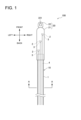
- FIG. 1 is a diagram illustrating an optical fiber cable with a traction tool according to one aspect of the present embodiment.
- FIG. 2 is a cross-sectional view taken along line AA in FIG.
- FIG. 3 is a plan view showing the intermittent optical fiber ribbon in the longitudinal direction.
- FIG. 4 is a diagram illustrating a measuring device for measuring the coefficient of dynamic friction of an optical fiber cable according to one aspect of the present embodiment.
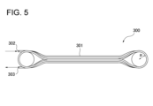
- FIG. 5 is a diagram illustrating a pumping device for evaluating pumping of an optical fiber cable.
- the present disclosure aims to provide an optical fiber cable with good low friction and flame retardancy.
- An optical fiber cable includes: (1) A cable core including a plurality of optical fiber cores or a plurality of optical fiber tape cores, a cable jacket disposed outside the cable core; a plurality of subunits including a coating material disposed within the cable core and covering the plurality of optical fiber cores or the plurality of optical fiber tape cores; at least one tensile strength member embedded in the cable jacket,
- the cable jacket has a dynamic friction coefficient of 0.5 or less with respect to the metal plate,
- the coating material has an oxygen index of 40 or more.
- the optical fiber cable since the cable jacket has a dynamic friction coefficient of 0.5 or less with respect to the metal plate, such an optical fiber cable has good low friction properties. Further, since the coating material covering the plurality of optical fiber core wires or the plurality of optical fiber tape core wires has an oxygen index of 40 or more, such an optical fiber cable has good flame retardancy. In this way, the optical fiber cable according to the above configuration has good low friction properties and flame retardance.
- the dynamic friction coefficient in the cable jacket is 0.3 or less;
- the oxygen index of the coating material may be 40 or more.
- the coefficient of dynamic friction of the cable jacket is 0.3 or less, so that such an optical fiber cable has good insertion characteristics.
- the oxygen index of the coating material is 40 or more, such an optical fiber cable has good flame retardancy. In this way, the optical fiber cable according to the above configuration has good insertion characteristics and flame retardancy.
- a plurality of the tensile strength members may be embedded at equal intervals within the layer of the cable jacket. According to this configuration, a plurality of tensile strength members are embedded at equal intervals in the layer of the cable jacket, so that bending anisotropy (presence or absence of an easy-to-bend direction) of the optical fiber cable is unlikely to occur. Note that “evenly” does not need to be strictly evenly spaced, but may be approximately evenly spaced.
- the cable jacket may contain a non-halogen resin. According to this configuration, since the cable jacket contains a non-halogen resin, it can contribute to reducing the environmental load.
- an optical fiber cable according to one aspect of the present disclosure (5) further comprising a presser tape wrapped around the outer periphery of the cable core; At least a portion of the presser tape may be flame retardant. According to this configuration, since at least a portion of the presser tape is flame retardant, the flame retardance of the optical fiber cable can be further improved.
- a multi-core connector having 24 or more fibers may be connected to the ends of the plurality of coated optical fibers or the ends of the plurality of coated optical fiber tapes. According to this configuration, the time required for connection to other optical fibers etc. can be shortened.
- FIGS. 1 and 2 An optical fiber cable 100 with a traction tool according to the present embodiment will be described with reference to FIGS. 1 and 2.
- "front-back direction” and “horizontal direction” will be referred to as appropriate. These directions are relative directions established for the fiber optic cable 100 with traction device illustrated in FIG.
- the "front-back direction” is a direction including the “front direction” and the “backward direction” with respect to the figure.
- “Left-right direction” is a direction including "left direction” and "right direction” with respect to the figure.
- FIG. 1 is a diagram illustrating an optical fiber cable 100 with a traction tool.
- FIG. 2 is a cross-sectional view taken along line AA in FIG.
- the optical fiber cable 100 with a traction tool includes an optical fiber cable 10 and a traction tool 20.
- the optical fiber cable 10 includes a cable main body 1, a plurality of multi-core connectors 2, and a pitch conversion section 3.
- the traction tool 20 includes a protective tube 21 and a pulling eye 22.
- the outer diameter of the optical fiber cable 10 is, for example, approximately 8 mm or more and 20 mm or less. Note that the outer diameter of the optical fiber cable 10 according to this embodiment is approximately 20 mm.
- the optical fiber cable 10 includes a cable core 4, a presser winding tape 5, a cable jacket 6, a tensile strength member 7, and a tear string (fibrous inclusion) 8. There is. Note that the cable core 4 , the presser tape 5 , the cable jacket 6 , the tensile strength member 7 , and the tear string 8 are included in the cable main body 1 .
- the cable core 4 includes a plurality of subunits 41 and a water absorbing material 42.
- the cable core 4 includes nine subunits 41, the number of subunits 41 included in the cable core 4 is not limited to this.
- each subunit 41 accommodates 96 optical fibers, the number of optical fibers is not limited to this.
- the optical fiber cable 10 accommodates 864 optical fibers.
- Each subunit 41 includes a plurality of optical fiber tape cores 411 and a covering material 412.
- an optical fiber ribbon 411 is a plurality of optical fibers 411A to 411L arranged in parallel in a direction perpendicular to the longitudinal direction of the plurality of optical fibers 411A to 411L. 411L, there are intermittently in the longitudinal direction a connecting part 413 in which adjacent optical fibers are connected and a non-connecting part 414 in which adjacent optical fibers are not connected. This is an intermittent connection type optical fiber ribbon.
- the optical fiber ribbon 411 includes 12 optical fibers (optical fibers 411A to 411L). Therefore, each subunit 41 accommodates eight optical fiber ribbons 411.
- each of the optical fibers 411A to 411L is, for example, 180 ⁇ m or 200 ⁇ m.
- the ultraviolet curing resin coating the glass of each optical fiber core wire 411A to 411L may be made flame retardant. Specifically, a flame retardant, which will be described later, may be mixed into the ultraviolet curing resin.
- the connecting portion 413 in the optical fiber tape core 411 is formed by applying a connecting resin 415 made of, for example, an ultraviolet curable resin, a thermosetting resin, or the like between the optical fiber cores.
- a connecting resin 415 made of, for example, an ultraviolet curable resin, a thermosetting resin, or the like between the optical fiber cores.
- the connecting resin 415 may be applied only to one side of the parallel surfaces formed by the parallel optical fiber cores 411A to 411L, or may be applied to both sides.
- the optical fiber ribbon 411 is made by, for example, applying tape resin to one or both sides of the parallel optical fibers 411A to 411L, and then connecting all the optical fibers 411A to 411L.
- the unconnected portion 414 may be formed by cutting a portion with a rotary blade or the like.
- the covering material 412 is arranged to cover the optical fiber tape core 411.
- the covering material 412 has a substantially annular shape in a cross-sectional view of the cable.
- the covering material 412 is made of a flame-retardant resin material, such as a vinyl chloride resin or a polyolefin resin, to which a flame-retardant inorganic substance such as magnesium hydroxide or aluminum hydroxide is added. Therefore, the covering material 412 has flame retardancy.
- the coating material 412 has an oxygen index of 40 or more.
- the holding tape 5 is wound around the outer periphery of the cable core 4.
- the thickness of the presser tape 5 is, for example, 0.13 mm or more and 0.15 mm or less.
- the presser tape 5 includes an inner layer 51 and an outer layer 52.
- the presser winding tape 5 has a two-layer structure.
- the structure of the presser tape 5 is not limited to the two-layer structure.
- the inner layer 51 is formed from a water-absorbing tape.
- the water-absorbing tape has been subjected to water-absorbing treatment, for example, by applying water-absorbing powder to a base fabric made of polyester or the like.
- the outer layer 52 is formed from a base material such as nonwoven fabric, PET, or glass.
- the substrate may be coated with a flame retardant.
- the flame retardant is preferably a non-halogen flame retardant such as a metal hydroxide, a nitrogen flame retardant, or a phosphorus flame retardant from the viewpoint of reducing environmental load.
- the flame retardant may be a halogen flame retardant such as a bromine flame retardant or a chlorine flame retardant. In this way, a part of the presser tape 5 (the outer layer 52 in this embodiment) is flame retardant.
- the cable jacket 6 is formed by extrusion molding a resin around the cable core 4 around which the holding tape 5 is wound.
- the thickness of the cable jacket 6 is, for example, 2.5 mm.
- the cable jacket 6 has a dynamic friction coefficient of, for example, 0.5 or less with respect to metal plates (for example, the first metal plate 201 and the second metal plate 202 illustrated in FIG. 4).
- the cable jacket 6 is made of vinyl chloride resin, non-halogen resin, or the like.
- the non-halogen resin include crosslinked polyethylene, polypropylene, polybutylene terephthalate, urethane, and nylon.
- the flame retardance of the cable jacket 6 can be improved.
- the cable jacket 6 may contain, for example, a silicone-based lubricant such as silicone or siloxane. In this case, the cable jacket 6 has low friction properties.
- the coefficient of dynamic friction of the cable jacket 6 with respect to the metal plate may be, for example, 0.3 or less.
- a plurality of tensile strength members 7 are embedded inside the cable jacket 6 at equal intervals, that is, at regular intervals. However, the spacing between the tensile strength members 7 may be approximately equal. In this embodiment, sixteen tensile strength members 7 are embedded inside the cable jacket 6.
- the diameter of the tensile strength member 7 is, for example, 0.5 mm.
- the tensile strength member 7 is made of fiber reinforced plastic (FRP) such as aramid FRP, glass FRP, carbon FRP, etc., for example.
- FRP fiber reinforced plastic
- the tensile strength body 7 may be formed of a liquid crystal polymer. It is preferable that the tensile strength member 7 is non-inductive.
- fiber reinforced plastic (FRP) is generally a flammable material. From the viewpoint of improving the flame retardance of the entire optical fiber cable 10, the tensile strength member 7 is arranged inside the cable jacket 6 at a position close to the center of the optical fiber cable 10, not near the surface layer of the cable jacket 6. It is preferable.
- a tearing string 8 is provided for tearing the cable jacket 6.
- the tear string 8 is linearly arranged in the layer of the cable jacket 6 in the longitudinal direction of the optical fiber cable 10 along the plurality of twisted optical fiber tape cores 411 .
- two tear strings 8 are provided.
- the two tear strings 8 are provided so as to face each other in a cross-sectional view of the cable. By pulling out the tearing string 8, the operator can tear the cable jacket 6 in the longitudinal direction and take out the subunit 41.
- the tear string 8 is fibrous and made of, for example, a tensile-resistant plastic material (for example, polyester).
- the multi-core connector 2 is, for example, a small 192-core connector.
- the multi-core connector 2 may be any connector having 24 or more cores, and is not limited to a 192-core connector. Further, multi-core connectors 2 having different numbers of cores may be used in combination.
- the optical fiber cable 10 includes, for example, four 192-fiber connectors and one 96-fiber connector.
- the multi-core connector 2 is housed in a protection tube 21. Note that in FIG. 1, only three multi-core connectors 2 are shown for convenience of illustration.
- the multi-fiber connector 2 is connected to an end of an optical fiber tape core 411 (see FIG. 3). However, the multi-fiber connector 2 may be connected to the ends of the optical fiber cores 411A to 411L (see FIG. 3).
- the pitch converter 3 is provided between the end of the optical fiber tape 411 and the end of the multi-fiber connector 2.
- the pitch converter 3 is configured to convert the pitch of the optical fibers 411A to 411L.
- the pitch of the optical fibers 411A to 411L in the optical fiber ribbon 411 is 200 ⁇ m
- the arrangement pitch in the multi-fiber connector 2 is 250 ⁇ m.
- the pitch conversion unit 3 converts the pitch of the optical fibers 411A to 411L from 200 ⁇ m to 250 ⁇ m by separating the plurality of optical fibers 411A to 411L into single cores and widening the pitch.
- a plurality of optical fibers 411A to 411L are connected to the multi-core connector 2 at a pitch of 250 ⁇ m.
- the pitch converter 3 may be omitted if there is no need to convert the pitch.
- the protection tube 21 has a substantially cylindrical shape.
- the front end of the protection tube 21 is spherical.
- the outer diameter of the protection tube 21 is, for example, 25 mm or less.
- the protective tube 21 is provided at the front end of the optical fiber cable 100 with a traction device.
- the surface of the protection tube 21 is coated with, for example, polyvinyl chloride.
- the outer diameter of the protective tube 21 is larger than the outer diameter of the cable main body 1 and the outer diameter of the pulling eye 22.
- the rear end of the pooling eye 22 is connected to the front end of the protection tube 21.
- the pulling eye 22 is made of a material with sufficient strength to pull the optical fiber cable 10. Such a material is, for example, a metal such as iron.
- the pooling eye 22 has a cavity 221. The installer (worker) can pull the optical fiber cable 10 by, for example, connecting a wire or the like to the cavity 221 and pulling the wire with a winch.
- the inventor conducted an experiment using a measuring device 200 illustrated in FIG. 4 in order to measure the coefficient of dynamic friction in the cable jacket 6.
- the measuring device 200 includes a first metal plate 201, a second metal plate 202, and four cylindrical members 203. Note that the four cylindrical members 203 are inserted into holes provided at the four corners of the first metal plate 201 and the second metal plate 202, respectively. In FIG. 4, only two cylindrical members 203 are shown for convenience of illustration. Further, the first metal plate 201 and the second metal plate 202 are flat plates made of stainless steel in order to imitate the wall surface of a duct used for passing an optical fiber cable.
- the inventor sandwiched the optical fiber cable between a first metal plate 201 and a second metal plate 202 disposed above the first metal plate 201, and applied a load to the second metal plate 202. From this state, the coefficient of dynamic friction in the cable jacket was measured by pulling the optical fiber cable in the longitudinal direction of the metal plate (rightward in FIG. 4). In addition, in the experiment, a load of about 2.0 kg was applied to the second metal plate 202. The length of the optical fiber cable is approximately 300 mm. The length in the longitudinal direction of the first metal plate 201 and the second metal plate 202 is approximately 150 mm. The pulling speed for fiber optic cables is approximately 500 mm/min. In addition, in this embodiment, the dynamic friction coefficient was evaluated using the average value of the traction tension. Furthermore, the optical fiber cable used in the experiment was the 864-core optical fiber cable illustrated in FIG. 1.
- the inventor conducted a pumping test in accordance with IEC using the pumping device 300 illustrated in FIG.
- the length of the pipe 301 is 1000 m, and it is turned back every 100 m.
- the radius of curvature R of the pipe 301 is 40 times the inner diameter of the pipe, and the inner diameter of the pipe 301 is 30 mm.
- the outer diameter of the optical fiber cable 10 is 20 mm.
- the opening 302 is the inlet for air and the optical fiber cable, and the opening 303 is the outlet for the air and the optical fiber cable. Note that the air pressure was 1.3 MPa or more and 1.5 MPa or less.
- Plenum Test In a combustion test according to UL910, flame retardancy is evaluated by performing a combustion test according to the flame retardant standards determined by UL (Underwriters Laboratory). This combustion test may vary depending on the shape of the sample, but generally speaking, the order of combustion performance is CMX (combustion test, usually referred to as VW-1 test), CM (vertical tray combustion test), and CMR (riser riser test). Grades such as CMP (Plenum Test) and CMP (Plenum Test) are set.
- the plenum test adopted in this embodiment is a test assuming that an optical fiber cable is installed in a plenum space, which is a space where air is constantly flowing due to air conditioning. The plenum space is, for example, an attic space.
- the flame retardance of the optical fiber cable was evaluated by igniting the optical fiber cable arranged in the plenum space and evaluating the flame spread and smoke generation properties of the optical fiber cable.
- optical fiber cables that met a predetermined standard in the combustion test according to plenum test UL910 were evaluated as good, and optical fiber cables that did not meet the predetermined standards were evaluated as poor.
- the optical fiber cable conforming to class B or higher in the CPR standard is very good
- the optical fiber cable conforming to class C in the CPR standard is good
- the optical fiber cable conforms to class C or higher in the CPR standard Optical fiber cables that did not meet the criteria were rated as defective.
- Table 1 shows the results of each experiment regarding the optical fiber cable according to Experimental Examples 1 to 4.
- Experimental example 1 will be explained.
- the oxygen index of the coating material provided in the optical fiber cable according to Experimental Example 1 is 45, and the oxygen index of the cable jacket is 42.
- the coefficient of dynamic friction in the cable jacket of the optical fiber cable according to Experimental Example 1 was 0.7.
- the pumping distance was 600 m. Therefore, the pumping evaluation of the optical fiber cable according to Experimental Example 1 was poor.
- the optical fiber cable according to Experimental Example 1 satisfied the predetermined standards in the combustion test according to the plenum test UL910, and therefore was evaluated as good in the combustion test according to the plenum test UL910. Furthermore, since the optical fiber cable according to Experimental Example 1 complied with Class B in the CPR standard, it was evaluated as very good in the combustion test based on the European Construction Materials Regulations.
- the oxygen index of the coating material provided in the optical fiber cable according to Experimental Example 2 is 38, and the oxygen index of the cable jacket is 40.
- the coefficient of dynamic friction in the cable jacket of the optical fiber cable according to Experimental Example 2 was 0.45.
- the pumping distance was 1100 m. Therefore, the pumping evaluation of the optical fiber cable according to Experimental Example 2 was good.
- the optical fiber cable according to Experimental Example 2 did not meet the predetermined standards in the combustion test according to the plenum test UL910, so it was evaluated as defective in the combustion test according to the plenum test UL910. Furthermore, since the optical fiber cable according to Experimental Example 2 complied with C class in the CPR standard, it was evaluated as good in the combustion test based on the European Construction Materials Regulations.
- the oxygen index of the coating material provided in the optical fiber cable according to Experimental Example 3 is 45, and the oxygen index of the cable jacket is 40.
- the coefficient of dynamic friction in the cable jacket of the optical fiber cable according to Experimental Example 3 was 0.5.
- the pumping distance was 1000 m. Therefore, the pumping evaluation of the optical fiber cable according to Experimental Example 3 was good.
- the optical fiber cable according to Experimental Example 3 satisfied the predetermined standards in the combustion test according to the plenum test UL910, and therefore was evaluated as good in the combustion test according to the plenum test UL910. Furthermore, since the optical fiber cable according to Experimental Example 3 conformed to class B in the CPR standard, it was evaluated as very good in the combustion test based on the European Construction Materials Regulations.
- the oxygen index of the coating material provided in the optical fiber cable according to Experimental Example 4 is 40, and the oxygen index of the cable jacket is 38.
- the coefficient of dynamic friction in the cable jacket of the optical fiber cable according to Experimental Example 4 was 0.3.
- the pumping distance was 2000 m. Therefore, the pumping evaluation of the optical fiber cable according to Experimental Example 4 was very good.
- the optical fiber cable according to Experimental Example 4 satisfied the predetermined standards in the combustion test according to the plenum test UL910, and therefore was evaluated as good in the combustion test according to the plenum test UL910. Furthermore, since the optical fiber cable according to Experimental Example 4 complied with C class in the CPR standard, it was evaluated as good in the combustion test based on the European Construction Materials Regulations.
- the optical fiber cable 10 in which the dynamic friction coefficient in the cable jacket 6 was 0.3 or less had very good insertion characteristics.
- the coefficient of dynamic friction between the cable jacket 6 and the metal plate is 0.5 or less, so the optical fiber cable 10 has good low friction properties.
- the oxygen index of the coating material 412 is 40 or more, the optical fiber cable 10 has good flame retardancy.
- the optical fiber cable 10 has good low friction and flame retardant properties.
- the optical fiber cable 10 if the dynamic friction coefficient of the cable jacket 6 is 0.3 or less, the optical fiber cable 10 has better insertion characteristics.
- a plurality of tensile strength members 7 are embedded in the cable jacket 6 at equal intervals. Therefore, in the optical fiber cable 10, bending anisotropy is less likely to occur.
- the cable jacket 6 includes a non-halogen resin, which can contribute to reducing the environmental load.
- the outer layer 52 of the presser wrapping tape 5 is flame retardant, so the flame retardance of the optical fiber cable 10 can be further improved.
- each subunit 41 has flame retardancy. That is, since each subunit 41 can be made flame retardant, even a single subunit can have flame retardancy.
- the 192-fiber type multi-core connector 2 and the 96-fiber type multi-core connector 2 are connected to the ends of the plurality of optical fiber tape cores 411. That is, multi-core connectors having 24 or more fibers are connected to the ends of the plurality of optical fiber tape cores 411. Therefore, according to the optical fiber cable 10, the time required for connection with other optical fibers etc. can be shortened.
- the optical fiber cable 10 includes the multi-core connector 2 and the pitch converter 3, but it is not necessary to include at least one of the multi-core connector 2 and the pitch converter 3.
- the number of multi-core connectors 2 provided in the optical fiber cable 10 and the number of fibers of the multi-core connector 2 are not limited to the numbers exemplified in the above embodiment.
- the optical fiber cable 10 may include nine 96-fiber connectors.
- the cable core 4 accommodates a plurality of optical fibers assembled as an optical fiber ribbon 411, but each of the plurality of optical fibers is a single optical fiber core. It may be a line.
- the optical fiber cable 10 is provided with the presser winding tape 5, but the presser winding tape 5 may not be provided.
Landscapes
- Physics & Mathematics (AREA)
- General Physics & Mathematics (AREA)
- Optics & Photonics (AREA)
- Light Guides In General And Applications Therefor (AREA)
- Insulated Conductors (AREA)
Priority Applications (4)
| Application Number | Priority Date | Filing Date | Title |
|---|---|---|---|
| EP22932230.0A EP4495651A4 (en) | 2022-03-18 | 2022-03-18 | Optical fiber cable |
| JP2024507462A JP7754281B2 (ja) | 2022-03-18 | 2022-03-18 | 光ファイバケーブル |
| PCT/JP2022/012824 WO2023175961A1 (ja) | 2022-03-18 | 2022-03-18 | 光ファイバケーブル |
| US18/840,702 US20250164724A1 (en) | 2022-03-18 | 2022-03-18 | Optical fiber cable |
Applications Claiming Priority (1)
| Application Number | Priority Date | Filing Date | Title |
|---|---|---|---|
| PCT/JP2022/012824 WO2023175961A1 (ja) | 2022-03-18 | 2022-03-18 | 光ファイバケーブル |
Publications (1)
| Publication Number | Publication Date |
|---|---|
| WO2023175961A1 true WO2023175961A1 (ja) | 2023-09-21 |
Family
ID=88023020
Family Applications (1)
| Application Number | Title | Priority Date | Filing Date |
|---|---|---|---|
| PCT/JP2022/012824 Ceased WO2023175961A1 (ja) | 2022-03-18 | 2022-03-18 | 光ファイバケーブル |
Country Status (4)
| Country | Link |
|---|---|
| US (1) | US20250164724A1 (https=) |
| EP (1) | EP4495651A4 (https=) |
| JP (1) | JP7754281B2 (https=) |
| WO (1) | WO2023175961A1 (https=) |
Citations (7)
| Publication number | Priority date | Publication date | Assignee | Title |
|---|---|---|---|---|
| JPS61179517U (https=) * | 1985-04-26 | 1986-11-08 | ||
| JP2001051169A (ja) * | 1999-08-09 | 2001-02-23 | Sumitomo Electric Ind Ltd | 光ケーブル |
| JP2011257603A (ja) * | 2010-06-09 | 2011-12-22 | Sumitomo Electric Ind Ltd | コネクタ付集合光ケーブル |
| US20130129290A1 (en) * | 2011-11-23 | 2013-05-23 | David Keller | Fiber optic cable |
| JP2015517679A (ja) | 2012-05-02 | 2015-06-22 | エーエフエル・テレコミュニケーションズ・エルエルシー | リボン型光ファイバー構造体を有する円形で小径の光ケーブル |
| US20190101715A1 (en) * | 2016-06-23 | 2019-04-04 | Corning Optical Communications LLC | Fire retardant optical fiber cable |
| JP2020204752A (ja) * | 2019-06-19 | 2020-12-24 | 住友電気工業株式会社 | 光ファイバケーブル |
-
2022
- 2022-03-18 WO PCT/JP2022/012824 patent/WO2023175961A1/ja not_active Ceased
- 2022-03-18 EP EP22932230.0A patent/EP4495651A4/en active Pending
- 2022-03-18 JP JP2024507462A patent/JP7754281B2/ja active Active
- 2022-03-18 US US18/840,702 patent/US20250164724A1/en active Pending
Patent Citations (7)
| Publication number | Priority date | Publication date | Assignee | Title |
|---|---|---|---|---|
| JPS61179517U (https=) * | 1985-04-26 | 1986-11-08 | ||
| JP2001051169A (ja) * | 1999-08-09 | 2001-02-23 | Sumitomo Electric Ind Ltd | 光ケーブル |
| JP2011257603A (ja) * | 2010-06-09 | 2011-12-22 | Sumitomo Electric Ind Ltd | コネクタ付集合光ケーブル |
| US20130129290A1 (en) * | 2011-11-23 | 2013-05-23 | David Keller | Fiber optic cable |
| JP2015517679A (ja) | 2012-05-02 | 2015-06-22 | エーエフエル・テレコミュニケーションズ・エルエルシー | リボン型光ファイバー構造体を有する円形で小径の光ケーブル |
| US20190101715A1 (en) * | 2016-06-23 | 2019-04-04 | Corning Optical Communications LLC | Fire retardant optical fiber cable |
| JP2020204752A (ja) * | 2019-06-19 | 2020-12-24 | 住友電気工業株式会社 | 光ファイバケーブル |
Non-Patent Citations (1)
| Title |
|---|
| See also references of EP4495651A4 |
Also Published As
| Publication number | Publication date |
|---|---|
| JPWO2023175961A1 (https=) | 2023-09-21 |
| EP4495651A1 (en) | 2025-01-22 |
| US20250164724A1 (en) | 2025-05-22 |
| JP7754281B2 (ja) | 2025-10-15 |
| EP4495651A4 (en) | 2025-04-16 |
Similar Documents
| Publication | Publication Date | Title |
|---|---|---|
| JP7156181B2 (ja) | 光ファイバケーブル | |
| CN101592765B (zh) | 室内使用的对弯曲不敏感的引入光缆 | |
| US12535645B2 (en) | Optical fiber cable and cable with connector | |
| US11994730B2 (en) | Optical fiber cable | |
| US6934452B2 (en) | Optical fiber cables | |
| JP2019164369A (ja) | 装甲された可撓性光ファイバーアセンブリ | |
| CN104160316A (zh) | 紧凑、低成本外部设施或室内/室外光缆 | |
| EP3198319B1 (en) | Optical fiber cable | |
| CN201413422Y (zh) | 一种入户预连接光缆 | |
| CN105051586A (zh) | 直径减小的多模光纤电缆 | |
| US12379561B2 (en) | Method for laying optical fiber cable | |
| WO2023175961A1 (ja) | 光ファイバケーブル | |
| JP5546412B2 (ja) | 光ケーブル | |
| JP2005208430A (ja) | 光ケーブル | |
| JP2005202265A (ja) | 耐火型光ケーブル | |
| TWM594154U (zh) | 加強型光纖纜線 | |
| CN210294631U (zh) | 气吹微缆 | |
| JP2006065215A (ja) | 光ケーブル | |
| WO2022249756A1 (ja) | 光ファイバケーブル | |
| JP2001116966A (ja) | 屋内用光ファイバケーブル | |
| WO2023113012A1 (ja) | 光ファイバケーブル | |
| WO2023002971A1 (ja) | 光ファイバケーブル | |
| JP2025077224A (ja) | 光ファイバケーブル | |
| JP7743874B2 (ja) | 光ファイバケーブルおよび光ファイバケーブル接続システム | |
| WO2013187109A1 (ja) | 光ファイバケーブル |
Legal Events
| Date | Code | Title | Description |
|---|---|---|---|
| 121 | Ep: the epo has been informed by wipo that ep was designated in this application |
Ref document number: 22932230 Country of ref document: EP Kind code of ref document: A1 |
|
| WWE | Wipo information: entry into national phase |
Ref document number: 18840702 Country of ref document: US |
|
| ENP | Entry into the national phase |
Ref document number: 2024507462 Country of ref document: JP Kind code of ref document: A |
|
| WWE | Wipo information: entry into national phase |
Ref document number: 2022932230 Country of ref document: EP |
|
| NENP | Non-entry into the national phase |
Ref country code: DE |
|
| ENP | Entry into the national phase |
Ref document number: 2022932230 Country of ref document: EP Effective date: 20241018 |
|
| WWP | Wipo information: published in national office |
Ref document number: 18840702 Country of ref document: US |