WO2023171072A1 - 障害物検知装置、障害物検知方法及びプログラム - Google Patents
障害物検知装置、障害物検知方法及びプログラム Download PDFInfo
- Publication number
- WO2023171072A1 WO2023171072A1 PCT/JP2022/046099 JP2022046099W WO2023171072A1 WO 2023171072 A1 WO2023171072 A1 WO 2023171072A1 JP 2022046099 W JP2022046099 W JP 2022046099W WO 2023171072 A1 WO2023171072 A1 WO 2023171072A1
- Authority
- WO
- WIPO (PCT)
- Prior art keywords
- sonar
- interference
- circuit
- transmission
- vehicle
- Prior art date
- Legal status (The legal status is an assumption and is not a legal conclusion. Google has not performed a legal analysis and makes no representation as to the accuracy of the status listed.)
- Ceased
Links
Images








Classifications
-
- G—PHYSICS
- G01—MEASURING; TESTING
- G01S—RADIO DIRECTION-FINDING; RADIO NAVIGATION; DETERMINING DISTANCE OR VELOCITY BY USE OF RADIO WAVES; LOCATING OR PRESENCE-DETECTING BY USE OF THE REFLECTION OR RERADIATION OF RADIO WAVES; ANALOGOUS ARRANGEMENTS USING OTHER WAVES
- G01S15/00—Systems using the reflection or reradiation of acoustic waves, e.g. sonar systems
- G01S15/88—Sonar systems specially adapted for specific applications
- G01S15/93—Sonar systems specially adapted for specific applications for anti-collision purposes
- G01S15/931—Sonar systems specially adapted for specific applications for anti-collision purposes of land vehicles
-
- G—PHYSICS
- G01—MEASURING; TESTING
- G01S—RADIO DIRECTION-FINDING; RADIO NAVIGATION; DETERMINING DISTANCE OR VELOCITY BY USE OF RADIO WAVES; LOCATING OR PRESENCE-DETECTING BY USE OF THE REFLECTION OR RERADIATION OF RADIO WAVES; ANALOGOUS ARRANGEMENTS USING OTHER WAVES
- G01S15/00—Systems using the reflection or reradiation of acoustic waves, e.g. sonar systems
- G01S15/02—Systems using the reflection or reradiation of acoustic waves, e.g. sonar systems using reflection of acoustic waves
- G01S15/06—Systems determining the position data of a target
- G01S15/08—Systems for measuring distance only
- G01S15/32—Systems for measuring distance only using transmission of continuous waves, whether amplitude-, frequency-, or phase-modulated, or unmodulated
- G01S15/34—Systems for measuring distance only using transmission of continuous waves, whether amplitude-, frequency-, or phase-modulated, or unmodulated using transmission of continuous, frequency-modulated waves while heterodyning the received signal, or a signal derived therefrom, with a locally-generated signal related to the contemporaneously transmitted signal
-
- G—PHYSICS
- G01—MEASURING; TESTING
- G01S—RADIO DIRECTION-FINDING; RADIO NAVIGATION; DETERMINING DISTANCE OR VELOCITY BY USE OF RADIO WAVES; LOCATING OR PRESENCE-DETECTING BY USE OF THE REFLECTION OR RERADIATION OF RADIO WAVES; ANALOGOUS ARRANGEMENTS USING OTHER WAVES
- G01S7/00—Details of systems according to groups G01S13/00, G01S15/00, G01S17/00
- G01S7/52—Details of systems according to groups G01S13/00, G01S15/00, G01S17/00 of systems according to group G01S15/00
- G01S7/523—Details of pulse systems
- G01S7/524—Transmitters
-
- G—PHYSICS
- G01—MEASURING; TESTING
- G01S—RADIO DIRECTION-FINDING; RADIO NAVIGATION; DETERMINING DISTANCE OR VELOCITY BY USE OF RADIO WAVES; LOCATING OR PRESENCE-DETECTING BY USE OF THE REFLECTION OR RERADIATION OF RADIO WAVES; ANALOGOUS ARRANGEMENTS USING OTHER WAVES
- G01S7/00—Details of systems according to groups G01S13/00, G01S15/00, G01S17/00
- G01S7/52—Details of systems according to groups G01S13/00, G01S15/00, G01S17/00 of systems according to group G01S15/00
- G01S7/534—Details of non-pulse systems
-
- G—PHYSICS
- G01—MEASURING; TESTING
- G01S—RADIO DIRECTION-FINDING; RADIO NAVIGATION; DETERMINING DISTANCE OR VELOCITY BY USE OF RADIO WAVES; LOCATING OR PRESENCE-DETECTING BY USE OF THE REFLECTION OR RERADIATION OF RADIO WAVES; ANALOGOUS ARRANGEMENTS USING OTHER WAVES
- G01S15/00—Systems using the reflection or reradiation of acoustic waves, e.g. sonar systems
- G01S15/88—Sonar systems specially adapted for specific applications
- G01S15/93—Sonar systems specially adapted for specific applications for anti-collision purposes
- G01S15/931—Sonar systems specially adapted for specific applications for anti-collision purposes of land vehicles
- G01S2015/937—Sonar systems specially adapted for specific applications for anti-collision purposes of land vehicles sensor installation details
- G01S2015/938—Sonar systems specially adapted for specific applications for anti-collision purposes of land vehicles sensor installation details in the bumper area
Definitions
- the present disclosure relates to an obstacle detection device, an obstacle detection method, and a program.
- the present disclosure provides an obstacle detection device that can reduce the possibility of false detection of an obstacle due to interference waves.
- An obstacle detection device includes a transmission circuit, a reception circuit, an object detection circuit, an interference detection circuit, and a determination circuit.
- the transmission circuit transmits a frequency-modulated transmission signal.
- the receiving circuit receives a signal from the outside.
- the object detection circuit detects an object present in the transmission direction of the transmission signal based on the reflected wave of the transmission signal received by the reception circuit.
- the interference detection circuit detects, as interference, another transmission signal transmitted from another transmission circuit different from the transmission circuit, based on the signal received by the reception circuit.
- the determination circuit determines a frequency modulation pattern to be applied to the transmission signal and a transmission timing of the transmission signal based on the detection results of the object detection circuit and the interference detection circuit.
- the obstacle detection device it is possible to reduce the possibility of false detection of an obstacle due to interference waves.
- FIG. 1 is a diagram illustrating an example of the configuration of a vehicle equipped with an in-vehicle system according to an embodiment.
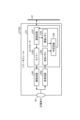
- FIG. 2 is a diagram illustrating an example of the configuration of the sonar according to the embodiment.
- FIG. 3 is a diagram illustrating an example of the waveform of ultrasonic waves transmitted in a first pattern by the sonar according to the embodiment.
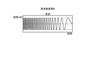
- FIG. 4 is a diagram illustrating an example of the waveform of ultrasonic waves received by the sonar according to the embodiment in a first pattern.
- FIG. 5 is a diagram illustrating an example of the waveform of ultrasonic waves transmitted in a second pattern by the sonar according to the embodiment.
- FIG. 1 is a diagram illustrating an example of the configuration of a vehicle equipped with an in-vehicle system according to an embodiment.
- FIG. 2 is a diagram illustrating an example of the configuration of the sonar according to the embodiment.
- FIG. 3 is a diagram illustrating an example of the waveform of ultrasonic waves transmitted in
- FIG. 6 is a diagram illustrating an example of the waveform of ultrasonic waves received by the sonar according to the embodiment in a second pattern.
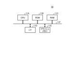
- FIG. 7 is a diagram illustrating an example of the hardware configuration of the sensor control device according to the embodiment.
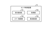
- FIG. 8 is a block diagram illustrating an example of functions included in the sensor control device according to the embodiment.
- FIG. 9 is a diagram illustrating an example of the positional relationship between the vehicle and other vehicles according to the embodiment.
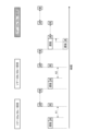
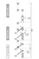
- FIG. 10 is a diagram illustrating an example of the processing flow of each part of the vehicle according to the embodiment.
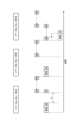
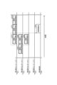
- FIG. 11 is a diagram illustrating an example of the processing flow of each part of the vehicle according to the embodiment.
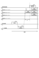
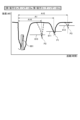
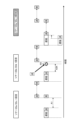
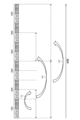
- FIG. 12 is an explanatory diagram showing an example of a received signal according to the embodiment.
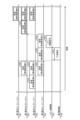
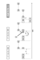
- FIG. 13 is a diagram illustrating an example of the processing flow of each part of the vehicle according to the embodiment.
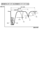
- FIG. 14 is an explanatory diagram showing an example of a received signal according to the embodiment.
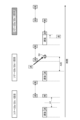
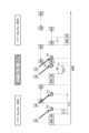
- FIG. 15 is a diagram showing an example of the interference relationship between the vehicle 1A and the vehicle 1B according to the embodiment.
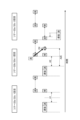
- FIG. 16 is a diagram illustrating an example of the interference relationship between the vehicle 1A and the vehicle 1B according to the embodiment.
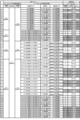
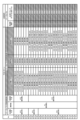
- FIG. 17 is a diagram illustrating an example of a data table according to the embodiment.
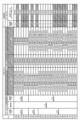
- FIG. 18 is a diagram illustrating an example of a data table according to the embodiment.
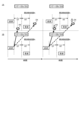
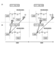
- FIG. 19 is a diagram schematically showing an example of an interference pattern of a data table according to the embodiment.
- FIG. 20 is a diagram schematically showing an example of the interference pattern of the data table according to the embodiment.
- FIG. 21 is a diagram schematically showing an example of an interference pattern of a data table according to the embodiment.
- FIG. 22 is a diagram schematically showing an example of the interference pattern of the data table according to the embodiment.
- FIG. 23 is a diagram schematically showing an example of the interference pattern of the data table according to the embodiment.
- FIG. 24 is a diagram schematically showing an example of the interference pattern of the data table according to the embodiment.
- FIG. 25 is a diagram schematically showing an example of an interference pattern of a data table according to the embodiment.
- FIG. 26 is a diagram schematically showing an example of the interference pattern of the data table according to the embodiment.
- FIG. 27 is a diagram schematically showing an example of the interference pattern of the data table according to the embodiment.
- FIG. 28 is a diagram schematically showing an example of the interference pattern of the data table according to the embodiment.
- FIG. 29 is a diagram schematically showing an example of the interference pattern of the data table according to the embodiment.
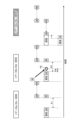
- FIG. 30 is a diagram illustrating an example of the processing flow of each part of the vehicle according to the embodiment.
- FIG. 31 is a flowchart illustrating an example of processing executed by the sensor control device according to the embodiment.
- FIG. 32 is a diagram illustrating an example of the flow of processing executed by the sensor control device according to the second modification.
- FIG. 33 is a diagram illustrating an example of a data table according to modification 3.
- FIG. 34 is a diagram illustrating an example of a data table according to modification 3.
- FIG. 35 is a diagram illustrating an example of a data table according to modification 3.
- Techniques are known that perform various controls to improve the running safety of a vehicle, such as operating automatic brakes and notifying the driver, based on object detection results by distance sensors.
- a sonar As a distance measurement sensor, a sonar is known that detects an object by transmitting ultrasonic waves and receiving reflected waves from objects around the vehicle.
- the vehicle 1 includes a steering control device 30, a speed control device 40, a vehicle control device 50, an HMI (Human Machine Interface) device 60, a sensor control device 70, and an alarm device 80.
- a steering control device 30 As shown in FIG. 1, the vehicle 1 includes a steering control device 30, a speed control device 40, a vehicle control device 50, an HMI (Human Machine Interface) device 60, a sensor control device 70, and an alarm device 80.
- HMI Human Machine Interface
- the in-vehicle system 100 includes a steering control device 30, a speed control device 40, a vehicle control device 50, an HMI device 60, a sensor control device 70, and an alarm device 80.
- vehicle 1 may be further equipped with other devices.
- the steering control device 30, the speed control device 40, the vehicle control device 50, the HMI device 60, the sensor control device 70, and the alarm device 80 are illustrated as separate devices, but some of these devices or Everything could be integrated.
- the vehicle 1 also includes a first front center sonar 21a, a second front center sonar 21b, a first front corner sonar 21c, a second front corner sonar 21d, a first rear center sonar 22a, a second rear center sonar 22b, a first It includes a rear corner sonar 22c and a second rear corner sonar 22d.
- the corner sonar 22c and the second rear corner sonar 22d are also simply referred to as sonar 21a, sonar 21b, sonar 21c, sonar 21d, sonar 22a, sonar 22b, sonar 22c, and sonar 22d.
- the sonar 21a, sonar 21b, sonar 21c, sonar 21d, sonar 22a, sonar 22b, sonar 22c, and sonar 22d are examples of the transmitter and the receiver.
- the sonar 21a, the sonar 21b, the sonar 21c, the sonar 21d, the sonar 22a, the sonar 22b, the sonar 22c, and the sonar 22d are provided at the front end of the vehicle 1. Further, the sonar 22a, the sonar 22b, the sonar 22c, and the sonar 22d are provided at the rear end of the vehicle 1.
- sonar 21a, sonar 21b, sonar 21c, sonar 21d, sonar 22a, sonar 22b, sonar 22c, and sonar 22d are not distinguished from sonar 22a, sonar 22b, sonar 22c, and sonar 22d, sonar 21 and sonar 22 Also called.
- sonar 21a, the sonar 21b, the sonar 21c, and the sonar 21d are collectively referred to as the front sonar 21, they are also referred to as the front sonar 21.
- the sonar 22a, the sonar 22b, the sonar 22c, and the sonar 22d are collectively referred to as the rear sonar 22, they are also referred to as the rear sonar 22.
- the sonar 21 and the sonar 22 are arranged on the vehicle 1 at positions advantageous for detecting surrounding objects or measuring distance.
- a plurality of sonar 21 and sonar 22 are arranged at a distance from each other on the front and rear bumpers of the vehicle 1, and detect objects in front and behind the vehicle 1.
- the sonar 21 and the sonar 22 are provided in the vehicle 1.
- the sonar 21 and the sonar 22 transmit frequency-modulated ultrasonic waves.
- Ultrasound is an example of a transmitted signal.
- the sonar 21 and the sonar 22 receive signals from the outside.
- the signal includes reflected ultrasound waves.
- the sonar 21 and the sonar 22 transmit ultrasonic waves and measure the time it takes to receive reflected waves reflected by objects around the vehicle 1, thereby detecting objects around the vehicle 1 and detecting the detected objects. Get distance information.
- the term "object” or “obstacle” includes pedestrians and other vehicles. Furthermore, objects that do not impede the movement of the vehicle 1, such as unevenness on the road surface, are not included in the obstacles.
- a sonar 21a and a sonar 21b are provided at the center of the front end of the vehicle 1. Further, at the front end of the vehicle 1, a sonar 21c and a sonar 21d are provided near the outer corner of the sonar 21a and the sonar 21b.
- a sonar 22a and a sonar 22b are provided at the center of the rear end of the vehicle 1. Further, at the rear end of the vehicle 1, a sonar 22c and a sonar 22d are provided near the outer corner of the sonar 22a and the sonar 22b.
- a detection range 210a indicates a range in which the sonar 21a can detect an object
- a detection range 210b indicates a range in which the sonar 21b can detect an object
- a detection range 210c indicates a range in which the sonar 21c can detect an object
- a detection range 210c indicates a range in which the sonar 21d can detect an object.
- the range in which this can be detected is defined as a detection range 210d.
- a detection range 220c is the range in which the sonar 22a can detect objects
- a detection range 220b is the range in which the sonar 22b can detect objects
- a detection range 220c is the range in which the sonar 22c can detect objects
- a detection range 220c is the range in which the sonar 22c can detect objects.
- the possible range is defined as a detection range 220d.
- each detection range 210 and detection range 220 are illustrated separately in FIG. 1, in reality, adjacent detection ranges 210 and adjacent detection ranges 220 may overlap.
- the sonar 21a, the sonar 21b, the sonar 22a, and the sonar 22b are not distinguished from each other, they are also referred to as center sonar 21a, 21b, 22a, and 22b.
- the sonar 21c, the sonar 21d, the sonar 22c, and the sonar 22d are not distinguished from each other, they are also referred to as corner sonar 21c, 21d, 22c, and 22d. Note that the vehicle 1 may omit the corner sonar 21c, 21d, 22c, and 22d.
- the sonar 22c or the second rear center sonar 22a detects it first.
- the sonar 22d or the sonar 22b detects it first.
- the installation location and number of sonar 21 and sonar 22 are not limited to the example shown in FIG. 1.
- the vehicle 1 includes an imaging device such as a camera, a radar, an antenna capable of receiving a GPS (Global Positioning System) signal, and a GPS that indicates the position of the vehicle 1 based on the received GPS signal.
- GPS Global Positioning System
- a GPS device (not shown) or the like that specifies coordinates may be provided as a sensor.
- Each sonar 21 and sonar 22 is also referred to as a sonar module.
- the sonar module includes a controller 23, a drive circuit 241, a receiving circuit 242, and a piezoelectric element 25.
- the sonar module transmits ultrasonic waves by applying voltage to the piezoelectric element 25.
- the controller 23 controls the drive circuit 241 to apply a voltage of, for example, 50 KHz to the piezoelectric element 25, so that the piezoelectric element 25 transmits ultrasonic waves of the same frequency.
- the transmitted ultrasound waves are in the form of pulses. When the pulsed ultrasonic waves hit a road surface or an obstacle, they are reflected and a portion of them returns to the sonar 21 and the sonar 22 .
- the piezoelectric element 25 converts the sound pressure of the returned reflected wave into voltage.
- the receiving circuit 242 amplifies and rectifies the voltage converted from the sound pressure by the piezoelectric element 25, and converts it into a sound wave reception intensity.
- the waveform showing the time change of the converted sound wave reception intensity is called an echo waveform.
- the received signal and the amplified received signal are alternating current, and the sonic received strength is the rectified version of the amplified received signal, so there is a difference between alternating current and direct current, but both are obtained by processing the received signal. , they are sometimes collectively referred to as received signals, regardless of whether they are alternating current or direct current.
- the receiving circuit 242 includes an amplifying circuit (not shown) that amplifies the voltage converted from the sound pressure by the piezoelectric element 25.
- the sonar module transmits ultrasonic waves using frequency modulation A or frequency modulation B different from frequency modulation A under the control of the sensor control device 70.
- Frequency modulation A and frequency modulation B are examples of frequency modulation patterns.
- frequency modulation A and frequency modulation B will be explained using FIGS. 3 to 6.
- the sonar module when using frequency modulation A as the frequency modulation pattern, transmits ultrasound by changing the frequency of the ultrasound from a low frequency to a high frequency.
- Frequency modulation A is an example of the first pattern or the second pattern.
- the sonar module receives reflected waves of ultrasound transmitted using frequency modulation A, the ultrasound is attenuated, so the amplitude decreases compared to when transmitting, as shown in Figure 4. The ultrasonic wave will be received.
- the sonar module transmits ultrasound by changing the frequency of the ultrasound from a high frequency to a low frequency.
- Frequency modulation B is an example of the first pattern or the second pattern.
- the sonar module receives reflected waves of ultrasound transmitted using frequency modulation A, the ultrasound is attenuated, so the amplitude decreases compared to when transmitting, as shown in Figure 6. The ultrasonic wave will be received.
- frequency modulation A and frequency modulation B are used as frequency modulation patterns, but the frequency modulation patterns are not limited to this.
- either frequency modulation A or frequency modulation B may be set to a constant frequency.
- frequency modulation may be performed in a pattern different from frequency modulation A and frequency modulation B.
- the controller 23 centrally controls the sonar modules.
- the controller 23 includes a communication circuit 231, a timer 232, a waveform memory 233, a threshold memory 234, and a determination circuit 235.
- Controller 23 is connected to sensor control device 70 via transmission line 27. Note that the controller 23 may be connected to the vehicle control device 50 and the like via the transmission line 27.
- the communication circuit 231 controls communication between the controller 23 and other devices. For example, the communication circuit 231 transmits and receives data to and from the sensor control device 70 via the transmission path 27. Communication circuit 231 receives sonar control signals from sensor control device 70 . Further, the communication circuit 231 transmits detection information indicating whether a reflected wave with an intensity exceeding a threshold value has been received, distance information indicating the distance from the vehicle 1 to the target, etc. to the sensor control device 70 .
- the timer 232 measures time.
- the sonar control signal includes a delay time when transmitting ultrasound waves.
- the timer 232 starts measuring time from the time when the communication circuit 231 receives the sonar control signal, and transmits a drive signal to drive the drive circuit 241 after the delay time has elapsed. Thereby, the sonar module can transmit ultrasonic waves at the transmission timing determined by the sonar control signal.
- the waveform memory 233 stores echo waveforms.
- the threshold memory 234 stores a short-distance interference detection threshold 810, an obstacle detection threshold 811, and a long-distance interference detection threshold 812 (see FIGS. 12 and 14).
- the short-range interference detection threshold 810 is an example of a second threshold.
- the obstacle detection threshold 811 is an example of a first threshold.
- the long-distance interference detection threshold 812 is an example of a third threshold. The short-range interference detection threshold 810, the obstacle detection threshold 811, and the long-range interference detection threshold 812 will be described later.
- the determination circuit 235 compares the amplified received signal with a short-range interference detection threshold 810, an obstacle detection threshold 811, and a long-range interference detection threshold 812 stored in the threshold memory 234. More precisely, the amplified received signal is rectified to obtain a sound wave reception intensity, and this sound wave reception intensity is compared with each detection threshold. Note that in the following description, in order to avoid complexity, it may be simply expressed as "comparing the received signal with a threshold value.”
- the determination circuit 235 determines the distance from the vehicle 1 to the object (the position where the short-range interference has occurred, the position of the obstacle, and the position where the long-range interference has occurred) based on the comparison result between the received signal and each detection threshold. Calculate the distance information shown.
- the determination circuit 235 sends the calculated distance information to the communication circuit 231.
- the communication circuit 231 transmits the distance information sent from the determination circuit 235 to the sensor control device 70 via the transmission path 27.
- Steering control device 30 controls the steering angle of vehicle 1 .
- the steering control device 30 is also referred to as a steering angle control device.
- the steering control device 30 is arranged, for example, at a position advantageous for assisting the power steering of the vehicle 1.
- the speed control device 40 controls acceleration and braking of the vehicle 1.
- the speed control device 40 is placed, for example, at a location advantageous for controlling the engine or motor and brakes.
- the vehicle control device 50 is a device that controls various behaviors of the vehicle 1, and is arranged near the steering control device 30 and the speed control device 40, for example.
- the HMI device 60 may include a display (not shown) that can display information, and a touch panel or switch that can accept operations by the user.
- the display and the touch panel may be configured as an integrated device.
- the display is also called a display section.
- the touch panel and switch are also referred to as an operation unit.
- a display section and an operation section included in the HMI device 60 are arranged around the driver's seat.
- the warning device 80 notifies the driver of other vehicles and obstacles detected by the vehicle control device 50 and sensor control device 70. Note that the alarm device 80 may be included in the HMI device 60.
- the sensor control device 70 controls the sonar module.
- the sensor control device 70 and the sonar module are examples of an obstacle detection device in this embodiment.
- the obstacle detection device includes the entire in-vehicle system 100, or any one of the steering control device 30, speed control device 40, vehicle control device 50, HMI device 60, and warning device 80 included in the in-vehicle system 100. Also good.
- the steering control device 30, the speed control device 40, the vehicle control device 50, the HMI device 60, and the sensor control device 70 are connected by wire via a local area network such as a CAN (Controller Area Network). Further, the sonar 21, the sonar 22, and the imaging device 16 may be connected to a local area network, or may be connected to the sensor control device 70 or the vehicle control device 50 through dedicated wiring.
- a local area network such as a CAN (Controller Area Network).
- the sonar 21, the sonar 22, and the imaging device 16 may be connected to a local area network, or may be connected to the sensor control device 70 or the vehicle control device 50 through dedicated wiring.
- the sensor control device 70 includes a CPU (Central Processing Unit) 11A, a ROM (Read Only Memory) 11B, a RAM (Random Access Memory) 11C, and an I/F (interface). 11D, flash memory 11E, etc. They are interconnected by a bus 11F, and have a hardware configuration using a normal computer.
- CPU Central Processing Unit
- ROM Read Only Memory
- RAM Random Access Memory
- I/F interface
- the CPU 11A is a calculation device that controls the entire sensor control device 70. Note that the CPU 11A is an example of a processor, and another processor or processing circuit may be provided in place of the CPU 11A.
- the ROM 11B stores programs and the like that implement various processes by the CPU 11A.
- the RAM 11C is, for example, a main storage device of the sensor control device 70, and stores data used for various processing by the CPU 11A.
- the I/F 11D is an interface for transmitting and receiving data. Further, the I/F 11D may send and receive information to and from other devices mounted on the vehicle 1 via a CAN or the like within the vehicle 1. Further, the flash memory 11E is an example of a writable nonvolatile storage medium. The ROM 11B, RAM 11C, and flash memory 11E are also referred to as storage units. Note that the sensor control device 70 may include other storage devices such as an HDD (Hard Disk Drive) instead of or in addition to the flash memory 11E.
- HDD Hard Disk Drive
- the hardware configuration of the steering control device 30, speed control device 40, vehicle control device 50, and HMI device 60 includes, for example, a processing circuit such as a CPU, ROM, RAM, I/F, and flash memory. shall be.
- the sensor control device 70 includes a first detection section 701, a sonar control section 702, an acquisition section 703, and a second detection section 704. Note that the functions provided by the sensor control device 70 are not limited to this.
- the first detection unit 701 detects an action that triggers the operation of the sonar module. For example, the first detection unit 701 detects the start of backward movement of the vehicle. In this case, the first detection unit 701 uses an electric signal (hereinafter also referred to as +B) output from the battery when the driver of the vehicle 1 shifts the gear into reverse as a signal that becomes a trigger for operating the sonar 22. Detect.
- +B an electric signal
- the sonar control unit 702 generates a sonar control signal to control the sonar module.
- the sonar module generates ultrasound signals according to the sonar control signals.
- the sonar control unit 702 determines the frequency modulation pattern to be applied to the ultrasound and the transmission timing of the ultrasound based on the detection result of the second detection unit 704.
- the sonar control unit 702 is an example of a determining unit. For example, the sonar control unit 702 determines a frequency modulation pattern and transmission timing for transmitting ultrasonic waves based on the detection result of the second detection unit 704, and generates a sonar control signal according to the determination.
- the acquisition unit 703 acquires detection information and distance information from the sonar module. Specifically, the acquisition unit 703 acquires the sonar module detection information and distance information received via the I/F 11D.
- the second detection unit 704 detects an object existing in the ultrasound transmission direction based on the reflected waves of the ultrasound received by the sonar module.
- the second detection section in this case is an example of an object detection section.
- the second detection unit 704 detects other ultrasonic waves transmitted from a transmitter different from the sonar module of the vehicle 1 that transmitted the ultrasonic waves as interference.
- the second detection unit 704 in this case is an example of an interference detection unit.
- interference refers to a phenomenon in which ultrasonic waves overlap and strengthen or weaken each other.
- the second detection unit 704 detects the presence or absence of short-range interference, the presence or absence of an obstacle, and the presence or absence of long-range interference based on the sonar module detection information and distance information acquired by the acquisition unit 703. do.
- the process flow of each part of the vehicle 1A according to the embodiment will be explained using FIG. 10.
- the driver of the vehicle 1A has performed an operation to shift the gear into reverse.
- the battery outputs +B.
- the first detection unit 701 detects +B and detects the start of backward movement of the vehicle 1A (processing 7011).
- the sonar control unit 702 generates a sonar control signal that controls the sonar 22 to transmit ultrasonic waves according to a predetermined frequency modulation pattern and transmission timing (processing 7021).
- the sonar control unit 702 sets the frequency modulation pattern to frequency modulation A and generates the sonar control signal according to a predetermined delay time.
- the predetermined frequency modulation pattern is set as frequency modulation A in the process 7021, but the predetermined frequency modulation pattern may be set as frequency modulation B.
- the sonar control unit 702 outputs the generated sonar control signal to the sonar 22a and the sonar 22c via the I/F 11D.
- the sonar control unit 702 generates a sonar control signal so that the sonar 22c transmits ultrasonic waves after a certain period of time has passed after the sonar 22a transmits the ultrasonic waves.
- the sonar 22a and the sonar 22c receive a sonar control signal via the communication circuit 231. Then, the sonar 22a transmits ultrasonic waves based on the received sonar control signal (processing 2221). Specifically, the sonar 22a transmits ultrasonic waves with a frequency modulation pattern of frequency modulation A and a normal delay time.
- the vehicle control device 50 transmits a control signal (hereinafter also referred to as a reverse signal) for moving the vehicle 1A backward (processing 501).
- a control signal hereinafter also referred to as a reverse signal
- Vehicles using existing technology often have a configuration in which a sonar transmits ultrasonic waves in response to detection of a reverse signal.
- the sonar 22a is configured to transmit ultrasonic waves in accordance with the detection of +B. Therefore, the sonar 22a can transmit ultrasonic waves earlier by the time indicated by arrow AT in FIG. 10 than when the sonar transmits ultrasonic waves in accordance with the detection of a reverse signal. This allows obstacles to be detected more quickly.
- the horizontal axis in FIG. 11 represents the time axis.
- the horizontal axis represents the time axis.
- the sonar 22a After the sonar 22a transmits the ultrasonic waves (process 2221), the sonar 22a performs a process of receiving reflected waves of the transmitted ultrasonic waves (process 2222). Furthermore, the sonar 22c performs a process of receiving the reflected wave of the ultrasonic wave transmitted by the sonar 22a in process 2221 (process 2211). Furthermore, the sonar 22b performs a process of receiving the reflected wave of the ultrasonic wave transmitted by the sonar 22a in process 2221 (process 2231).
- the sonar 22c transmits ultrasonic waves based on the received sonar control signal after a certain period of time has elapsed since the ultrasonic wave was transmitted by the sonar 22a (process 2221) (process 2212). After the sonar 22c transmits the ultrasonic waves, the sonar 22c performs a process of receiving reflected waves of the ultrasonic waves transmitted in process 2212 (process 2213).
- the determination circuits 235 of the sonar 22a, sonar 22c, and sonar 22b compare the received signal with a short-range interference detection threshold 810, an obstacle detection threshold 811, and a long-range interference detection threshold 812, respectively, and calculate distance information. .
- the communication circuits 231 of the sonar 22a, sonar 22c, and sonar 22b transmit distance information to the sensor control device 70.
- the sensor control device 70 receives distance information via the I/F 11D, and the second detection unit 704 detects the presence or absence of an obstacle based on the distance information (processing 7041).
- the second detection unit 704 detects that there is an obstacle when the sonar module receives the transmitted reflected waves multiple times (for example, three times) in succession. We are planning to detect it.
- the condition for detecting an obstacle is when a reflected wave is received three times in a row.
- the received signal refers to a signal obtained by rectifying a received ultrasonic signal.
- FIG. 12 shows a received signal obtained by rectifying the reflected wave of the sonar 22a received in processing 2222, a received signal obtained by rectifying the reflected wave of the sonar 22c received in processing 2211, a short-range interference detection threshold 810, an obstacle detection It shows the relationship between a threshold value 811, a long-distance interference detection threshold value 812, and a frequency modulation A801 that is a frequency modulation pattern during wave transmission.
- the solid line waveform in FIG. 12 represents an example of a received signal when an obstacle is present.
- the received signal shown in FIG. 12 includes a received wave peak P1 indicating the presence of an obstacle.
- the dotted line waveform in FIG. 12 shows an example of a received signal when near-field interference and long-range interference occur due to the influence of ultrasonic waves emitted by other vehicles. If near-field interference occurs in addition to the presence of an obstacle, the received signal will have two reception peaks P2 and P1. Furthermore, if there is long-distance interference in addition to the presence of an obstacle, the received signal will have two reception peaks P1 and P3.
- the received signal will have three reception peaks P2, P1, and P3.
- the sonar 22 detects the interference from the vehicle before receiving the reflected wave reflected by the vehicle 1B. It receives interference waves such as ultrasonic waves emitted by the sonar 22 of 1B and reflected waves of the ultrasonic waves. Therefore, P2, which mainly represents short-range interference by the vehicle 1B, appears before the peak P1, which represents the reflected wave reflected by the vehicle 1B.
- the amplitude of the peak P2 is larger than the amplitude of the peak P1 representing the reflected wave reflected by the vehicle 1B.
- the signal strength at the peak position decreases as the amplitude increases, so the signal strength satisfies peak P1>peak P2.
- the near-field interference detection threshold 810 is a signal strength threshold for identifying whether or not there is near-field interference. Specifically, based on the relationship of peak P1>peak P2, the short-range interference detection threshold 810 is set to a value smaller than the obstacle detection threshold 811.
- the sonar 22 after receiving the reflected wave reflected by the vehicle 1B, detects the interference caused by multiple reflections. Receive interference waves, etc. Therefore, after the peak P1 representing the reflected wave reflected by the vehicle 1B, there is a peak P3 representing long-distance interference mainly due to multiple reflections.
- the amplitude of the peak P3 is smaller than the amplitude of the peak P1 representing the reflected wave reflected by the vehicle 1B.
- the signal strength at the peak position decreases as the amplitude increases, so the signal strength satisfies peak P1 ⁇ peak P3.
- the long-distance interference detection threshold 812 is a signal strength threshold for identifying whether or not there is long-distance interference. Specifically, based on the relationship of peak P1 ⁇ peak P3, the long-distance interference detection threshold 812 is set to a value larger than the obstacle detection threshold 811.
- the determination circuit 235 compares the received signal with the obstacle detection threshold 811 and determines whether there is a peak below the obstacle detection threshold 811. If there are peaks below the obstacle detection threshold 811, the determination circuit 235 determines the number of peaks below the obstacle detection threshold 811.
- the determination circuit 235 determines that the peak P1 or P2 exists. In this case, the determination circuit 235 determines whether there is a peak below the short-range interference detection threshold 810.
- the determination circuit 235 determines that the peak P2 exists, and sets the distance value of A1K shown in FIG. Calculate as information.
- the determination circuit 235 determines that the peak P1 exists. In this case, the determination circuit 235 determines whether there is a peak other than the peak P1 that is lower than the long-distance interference detection threshold 812.
- the determination circuit 235 determines that peaks P1 and P3 exist, and the process shown in FIG.
- the two distance values A1 and A1E shown are calculated as distance information.
- the determination circuit 235 determines that the peak P1 exists, and as shown in FIG.
- the distance value of A1 shown is calculated as distance information.
- the determination circuit 235 compares the received signal with the near-field interference detection threshold 810, and determines whether there are any peaks below the near-field interference detection threshold 810.
- sonar performs distance detection using ToF (Time of Flight). Further, since the wave height of the reflected wave attenuates depending on the distance, the setting of each threshold value may be determined depending on the distance to the object.
- ToF Time of Flight
- the determination circuit 235 determines that peaks P2 and P1 exist. . At this time, the determination circuit 235 sets the peak with the largest amplitude as P2, the peak with the next largest amplitude as P1, and calculates the two distance values A1K and A1 shown in FIG. 12 as distance information.
- the determination circuit 235 determines that peaks P1 and P3 exist. At this time, the determination circuit 235 sets the peak with the largest amplitude as P1, the peak with the next largest amplitude as P3, and calculates the two distance values A1 and A1E shown in FIG. 12 as distance information.
- the determination circuit 235 determines whether there are any peaks below the short-range interference detection threshold 810.
- the determination circuit 235 detects the peaks P2, P1, and P3. It is determined that exists. At this time, the determination circuit 235 sets the peak with the largest amplitude as P2, the peak with the next largest amplitude as P1, and the peak with the next largest amplitude as P3, and calculates the three distance values A1K, A1, and A1E shown in FIG. is calculated as distance information.
- the determination circuit 235 does not need to detect a peak that exists at a later time than the peak P3 as a peak.
- the determination circuit 235 determines that P1 and P3 exist. At this time, the determination circuit 235 sets the peak with the largest amplitude as P1, the peak with the next largest amplitude as P3, and calculates the two distance values A1 and A1E shown in FIG. 12 as distance information.
- the determination circuit 235 does not need to detect a peak that exists at a later time than the peak P3 as a peak.
- the judgment circuit 235 determines whether there is a peak below the long-distance interference detection threshold 812. If there is no peak below the obstacle detection threshold 811 and the amplitude of the largest amplitude portion of the received signal is below the long-distance interference detection threshold 812, the determination circuit 235 determines that the peak P3 exists. . The determination circuit 235 sets this portion as a peak P3 and calculates the distance value of A1E shown in FIG. 12 as distance information.
- the determination circuit 235 determines that all of A1K, A1, and A1E The information indicating that the distance value has not been calculated is defined as distance information.
- the distance information calculated by the determination circuit 235 is sent to the communication circuit 231.
- the communication circuit 231 transmits the distance information sent out by the determination circuit 235 to the sensor control device 70.
- the transmitted distance information is then acquired by the acquisition unit 703 of the sensor control device 70.
- FIG. 12 describes the received signal obtained by rectifying the reflected wave of the sonar 22a received in the process 2222 and the received signal obtained by rectifying the reflected wave of the sonar 22c received in the process 2211.
- the received signal obtained by rectifying the reflected wave of the second center sonar 22b is also the same as that shown in FIG.
- the second detection unit 704 detects the obstacle based on the distance information calculated from the received signal obtained by rectifying the reflected waves received in processes 2222, 2211, and 2231. Detect presence.
- the second detection unit 704 detects that there are obstacles around the vehicle 1A. Detects the existence of On the other hand, in cases other than the above, the second detection unit 704 detects that there are no obstacles around the vehicle 1A.
- the second detection unit 704 may detect that there are no obstacles around the vehicle 1A even if the distance value of A1 is calculated from all of the received signals received in processing 2222, processing 2211, and processing 2231.
- the sonar control unit 702 generates a sonar control signal based on the detection result of the second detection unit 704 in process 7041 (process 7022). Specifically, when the second detection unit 704 detects that there is no obstacle, the sonar control unit 702 sets the frequency modulation pattern to frequency modulation A and transmits ultrasonic waves according to a predetermined delay time. A sonar control signal is generated to control the sonar 22 in this manner.
- the sonar control unit 702 determines the frequency modulation pattern to be frequency modulation A, and generates a sonar control signal according to a predetermined delay time. . Note that in this embodiment, in the process 7022, the frequency modulation pattern when an obstacle is detected is set to frequency modulation A, but the frequency modulation pattern when an obstacle is detected may be set to frequency modulation B.
- a sonar control signal for controlling the sonar 22 is generated as follows.
- the sonar control unit 702 transmits the generated sonar control signal to the sonar 22b and the sonar 22d via the I/F 11D.
- the sonar control unit 702 sends a sonar control signal to the sonar 22d so that the sonar 22b transmits the first ultrasonic wave after a certain period of time has passed after the sonar 22b transmits the first ultrasonic wave. generate.
- the sonar 22b and the sonar 22d receive a sonar control signal via the communication circuit 231. Then, the sonar 22b transmits the first ultrasonic wave according to the received sonar control signal (processing 2232). Specifically, the sonar 22b transmits the first ultrasonic wave with a frequency modulation pattern of frequency modulation A and a normal delay time.
- the sonar 22b After the sonar 22b transmits the ultrasonic wave, the sonar 22b performs a process of receiving the reflected wave of the first transmitted ultrasonic wave (process 2233). Furthermore, the sonar 22d performs a process of receiving the reflected wave of the first ultrasonic wave transmitted by the sonar 22b (process 2241).
- the sonar 22a performs a process of receiving the reflected wave of the first ultrasonic wave transmitted by the sonar 22b (process 2223).
- the sonar 22d transmits the first ultrasonic wave according to the received sonar control signal after a certain period of time has elapsed since the first ultrasonic wave was transmitted by the sonar 22b (processing 2242). After the sonar 22d transmits the ultrasound, the sonar 22d performs a process of receiving the reflected wave of the first transmitted ultrasound (process 2243).
- the determination circuits 235 of the sonar 22a, sonar 22c, and sonar 22b compare the received signal with a short-range interference detection threshold 810, an obstacle detection threshold 811, and a long-range interference detection threshold 812, respectively, and calculate distance information. .
- the communication circuits 231 of the sonar 22a, sonar 22c, and sonar 22b transmit distance information to the sensor control device 70.
- the sensor control device 70 receives the distance information via the I/F 11D, and the second detection unit 704 detects interference based on the distance information (processing 7042).
- FIG. 14 shows a received signal obtained by rectifying the reflected wave of the sonar 22b received in processing 2233, a received signal obtained by rectifying the reflected wave of the sonar 22d received in processing 2241, a short-range interference detection threshold 810, an obstacle detection It represents the relationship between the threshold value 811, the long-distance interference detection threshold value 812, and frequency modulation A821 or frequency modulation B822, which is a frequency modulation pattern during wave transmission.
- the processing of the determination circuit 235 is approximately the same as that in the case of FIG. A2K or B2K distance value is calculated instead of A1K, and A2E or B2E distance value is calculated instead of A1E distance value.
- the determination circuit 235 calculates A2, A2K, and A2E. Furthermore, when the sonar 22b and the sonar 22d transmit waves using frequency modulation B, the determination circuit 235 calculates B2, B2K, and B2E.
- the second detection unit 704 detects the near distance based on the distance information calculated from the received signal obtained by rectifying the reflected waves received in processes 2233, 2241, and 2223. Detects the presence or absence of distance interference, the presence or absence of obstacles, and the presence or absence of long-distance interference.
- the second detection unit 704 It is detected that there is near-field interference in the vehicle 1A. On the other hand, in cases other than the above, the second detection unit 704 detects that there is no short-range interference in the vehicle 1A.
- the second detection unit 704 detects the distance value of vehicle 1A. Detects the presence of obstacles in the surrounding area. On the other hand, in cases other than the above, the second detection unit 704 detects that there are no obstacles around the vehicle 1A.
- the second detection unit 704 Detects the presence of far-field interference. On the other hand, in cases other than the above, the second detection unit 704 detects that there is no long-distance interference in the vehicle 1A.
- the second detection unit 704 determines the frequency modulation pattern of the ultrasound to be transmitted next time based on the distance values of A1, A1K, A1E, A2 (or B2), A2K (or B2K), and A2E (or B2E). (Frequency modulation A or frequency modulation B) and an interference pattern used to determine transmission timing (no delay time or extended delay time) is detected.
- FIG. 15 shows that vehicle 1A shown in FIG. 9 moves backward in the direction in which vehicle 1B exists (the negative direction of the X-axis in FIG. 9), and vehicle 1B moves in the direction in which vehicle 1A exists (the negative direction of the It shows a change in the positional relationship of interference with the vehicle 1A and the vehicle 1B when traveling backward in the forward direction).
- the vehicle 1A starts moving backward toward the vehicle 1B
- the vehicle 1B starts moving backward toward the vehicle 1A
- the sonar 22a of the vehicle 1A transmits an ultrasonic wave
- the corresponding The ultrasonic waves reach the rear end of the vehicle 1B after the transmission time ST has elapsed.
- the determination circuit 235 of the sonar 22a and the sonar 22c of the vehicle 1A calculates the distance value of A1, for example, the distance value to the vehicle 1B.
- the sonar 22a and the sonar 22c of the vehicle 1A receive the ultrasonic waves transmitted from the vehicle 1B before the transmission time ST elapses. Therefore, near field interference KK occurs. Therefore, the determination circuit 235 of the sonar 22a and the sonar 22c of the vehicle 1A calculates the distance value of A1K, for example, the distance value related to the short-range interference KK.
- the determination circuit 235 of the sonar 22b and the sonar 22d of the vehicle 1A calculates the distance value of A2, for example, the distance value to the vehicle 1B.
- the sonar 22b and the sonar 22d of the vehicle 1A receive the ultrasonic waves transmitted from the vehicle 1B before the transmission time ST elapses. Therefore, near field interference KK occurs. Therefore, the determination circuit 235 of the sonar 22b and the sonar 22d of the vehicle 1A calculates the distance value of A2K, for example, the distance value related to the short-range interference KK.
- the sonar 22b of the vehicle 1A is higher than the point at which the sonar 22a of the vehicle 1A transmits the ultrasonic waves.
- the distance between vehicle 1A and vehicle 1B is closer at the time when the sound waves are transmitted. Therefore, the distance value of A2 will be smaller than A1, and the distance value of A2K will be smaller than the distance value of A1K.
- the vehicle 1B approaches the vehicle 1A, and the position where the short-range interference KK occurs (hereinafter also referred to as the interference position) also approaches the vehicle 1A.
- long-range interference EK occurs due to multiple reflections, etc.
- the interference position of long-range interference EK will also approach the vehicle 1A as time passes, as in the case of the above-mentioned short-range interference KK.
- FIG. 16 shows that vehicle 1A shown in FIG. 9 moves in the direction opposite to the direction in which vehicle 1B exists (the positive direction of the X axis in FIG. 9), and vehicle 1B moves in the opposite direction to the direction in which vehicle 1A exists. It represents a change in the positional relationship of interference with the vehicle 1A and the vehicle 1B when moving in the direction (negative direction of the X axis in FIG. 9).
- the vehicle 1A is moving in the opposite direction to the vehicle 1B, and the vehicle 1B is moving in the opposite direction to the vehicle 1A.
- the distance between the vehicle 1A and the vehicle 1B is longer at the time when the sonar 22b of the vehicle 1A transmits the ultrasonic wave. Therefore, the distance value of A2 will be greater than A1, and the distance value of A2K will be greater than the distance value of A1K.
- the vehicle 1B moves away from the vehicle IA, and the interference position of the near-field interference also moves away from the vehicle 1A.
- the second detection unit 704 compares the distance value of A1 with the distance value of A2 (or B2), compares the distance value of A1K with the distance value of A2K (or B2K), and compares the distance value of A1E with the distance value of A2K (or B2K). and the distance value of A2E (or B2E) to detect an interference pattern representing the relationship between the position of the vehicle 1A, the interference position of the short-range interference, the position of the obstacle, and the interference position of the long-range interference.
- the distance values of A1, A1K, and A1E used for detecting the interference pattern are the values obtained from the sonar 22a, but the values obtained from the sonar 22c and the distance values obtained from the sonar 22b are used.
- the average value or median value of the values obtained from the sonar 22a may be used.
- the distance values of A2 (or B2), A1K, A2K (or B2K), A1K, and A2K (or B2K) shall use the values obtained from the sonar 22b, but the values obtained from the sonar 22d, the sonar The average value or median value of the values obtained from the sonar 22a and the values obtained from the sonar 22a may be used.
- the sonar control unit 702 generates a sonar control signal based on the interference pattern detected by the second detection unit 704.
- the interference pattern detection process by the second detection unit 704 the type of frequency modulation of the next transmitted ultrasound (frequency modulation A or frequency modulation B), and the ultrasound transmission timing (faster) by the sonar control unit 702 will be described.
- Determination processing (hereinafter also referred to as ultrasonic wave transmission conditions) will be described.
- the second detection unit 704 detects an interference pattern based on a data table stored in the flash memory 11E or the like that determines the detection of the interference pattern and the transmission conditions of the ultrasound to be transmitted next time. do. Furthermore, the sonar control unit 702 determines the transmission conditions for the next ultrasonic wave to be transmitted based on the data table.
- “No.” in the data tables in FIGS. 17 and 18 represents a number that identifies an interference pattern.
- “sonar 22a/22c (frequency modulation A or frequency modulation B)” of “interference pattern” represents the first ultrasound transmission source and the frequency modulation pattern used for ultrasound transmission.
- “sonar 22b/22d (frequency modulation A or frequency modulation B)” of “interference pattern” represents the second ultrasound transmission source and the frequency modulation pattern used for ultrasound transmission.
- “sonar 22a/22c” in the “wave transmission condition” represents the third ultrasound transmission source.
- “frequency modulation” of “wave transmission conditions” represents the frequency modulation pattern used for the third ultrasound transmission.
- “wave transmission timing” of “wave transmission condition” represents whether the wave transmission timing of the third ultrasonic wave transmission is made early or late.
- making the wave transmission timing earlier means that the sonar 21 or the sonar 22 transmits ultrasonic waves without a predetermined normal delay time.
- delaying the wave transmission timing means that the sonar 21 or the sonar 22 transmits ultrasonic waves by extending a predetermined normal delay time by a predetermined time.
- “Near-range interference” of “Sonar 22a/22c (Frequency modulation A)" in “Interference pattern” indicates whether or not the distance value of A1K was measured (whether or not near-field interference was detected). There is. Further, “obstacle” of “sonar 22a/22c (frequency modulation A)” in “interference pattern” indicates whether the distance value of A1 has been measured (whether or not an obstacle has been detected). In addition, “Long-distance interference” of “Sonar 22a/22c (Frequency modulation A)” in “Interference pattern” indicates whether the distance value of A1E was measured (whether or not long-distance interference was detected). There is.
- “near-range interference” of “sonar 22b/22d (frequency modulation A)" in “interference pattern” represents the relationship between the distance value of A1K and the distance value of A2K (or B2K).
- “obstacle” of “sonar 22b/22d (frequency modulation A)” of “interference pattern” represents the relationship between the distance value of A1 and the distance value of A2 (or B2).
- “long distance interference” of “sonar 22b/22d (frequency modulation A)” in “interference pattern” represents the relationship between the distance value of A1E and the distance value of A2E (or B2E).
- FIG. 17 is an excerpt of the part representing the interference pattern when the distance value of A1 is measured from the data table according to the present embodiment.
- FIG. 18 is an excerpt of a portion of the data table according to this embodiment that represents an interference pattern when the distance value of A1 is not measured.
- the second detection unit 704 refers to the data table and detects the distance values of A1, A1K, A1E, A2 (or B2), A2K (or B2K), and A2E (or B2E) acquired as distance information by the acquisition unit 703. Identify the interference pattern. For example, if the acquisition unit 703 acquires the distance value of A1 and the distance value of A2, but does not acquire other distance values, and the distance value of A1>the distance value of A2, the second detection unit 704 refers to the data table and identifies that the interference pattern is "No. 1".
- the sonar control unit 702 refers to the data table and transmits the frequency modulation "frequency modulation A" and the transmission timing "earlier", which are the transmission conditions corresponding to the interference pattern "No. 1". Determine as a condition.
- “Sonar 22a/sonar 22c: first time” in FIG. 19 represents the first transmission and reception of ultrasonic waves by sonar 22a/sonar 22c.
- “sonar 22b/sonar 22d: first time” represents the first transmission and reception of ultrasonic waves by sonar 22b/sonar 22d.
- “sonar 22a/sonar 22c: second time” in FIG. 19 refers to the second time by sonar 22a/sonar 22c under the transmission conditions determined based on the reception result of the first transmitted ultrasonic wave. It shows the transmission and reception of ultrasonic waves.
- the distance value of A1 is measured in the first ultrasonic wave transmission
- the distance value of A2 is measured in the second ultrasonic wave transmission
- the sensor control device 70 speeds up the transmission timing of the ultrasonic waves. This allows obstacles to be detected quickly. Therefore, the sensor control device 70 can reduce the possibility of a collision between the vehicle 1 and another vehicle by detecting another vehicle at an early stage and notifying the driver of a warning.
- the wave transmission timing is set to be earlier.
- the frequency modulation pattern is set as frequency modulation A
- the frequency modulation pattern is set as frequency modulation B, so the frequency modulation in this case The pattern becomes frequency modulation A.
- the distance value of A1 is measured in the first ultrasonic wave transmission
- the distance value of A2 is measured in the second ultrasonic wave transmission
- the distance value of A1 is measured. This is a situation where the distance value is ⁇ A2. This indicates that other vehicles are moving away from vehicle 1. Further, since the distance value of A1K and the distance value of AIE are not measured, it can be seen that neither short-range interference nor long-range interference occurs.
- the sensor control device 70 delays the transmission timing of the ultrasonic waves. This allows it to detect obstacles further away. Therefore, the sensor control device 70 can detect another vehicle even if the other vehicle moves further away. Therefore, in the interference pattern "No. 2", the wave transmission timing is delayed.
- Interference pattern "No. 3" shown in FIG. 21 is a situation in which the distance value A1 is measured in the first ultrasonic wave transmission, and no distance value is measured in the second ultrasonic wave transmission. This indicates that no other vehicle is detected during the second ultrasonic wave transmission. Furthermore, since the distance value of A1K and the distance value of AIE are not measured, it can be seen that neither near-field interference KK nor long-range interference EK occurs.
- the wave transmission timing may be set earlier or later.
- the data table in FIG. 17 specifies that the wave transmission timing is to be advanced when the distance value of A2 is not measured. Therefore, in the interference pattern "No. 3", the wave transmission timing is set to be earlier.
- the distance value of A1 is measured in the first ultrasonic wave transmission, and the distance value of A2K and the distance value of A2 are measured in the second ultrasonic wave transmission. This is a situation where the distance value of A1>the distance value of A2. This indicates that there is short-range interference KK and that another vehicle is approaching vehicle 1.
- the distance value of A1 is measured in the first ultrasonic wave transmission, and the distance value of A2K and the distance value of A2 are measured in the second ultrasonic wave transmission. This is a situation where the distance value of A1 ⁇ the distance value of A2. This indicates that there is short-range interference KK and that other vehicles are moving away from the vehicle 1.
- the distance value of A1 is measured in the first ultrasonic wave transmission, the distance value of A2K is measured in the second ultrasonic wave transmission, and the distance value of A2 is measured. This is a situation where no value is measured. This indicates that there is short-range interference KK and that no other vehicle is detected by the second ultrasonic wave transmission.
- the distance value of A1 is measured in the first ultrasonic wave transmission, and the distance value of A2 and A2E are measured in the second ultrasonic wave transmission. This is a situation where the distance value of A1>the distance value of A2. This indicates that there is long-range interference EK and that another vehicle is approaching vehicle 1.
- the distance value of A1 is measured in the first ultrasonic wave transmission, and the distance value of A2 and the distance value of A2E are measured in the second ultrasonic wave transmission. This is a situation where the distance value of A1 ⁇ the distance value of A2. This indicates that there is long-range interference EK and that other vehicles are moving away from vehicle 1.
- the distance value of A1 is measured in the first ultrasonic wave transmission, the distance value of A2E is measured in the second ultrasonic wave transmission, and the distance value of A2 is measured. This is a situation where no value is measured. This indicates that there is long-distance interference EK and that no other vehicle is detected by the second ultrasonic wave transmission.
- interference patterns "No. 10", “No. 11", and “No. 12" have a small effect on long-range interference EK
- the distance value of A1K and the distance value of A2K are not measured, and the distance value of A1 is not measured.
- the influence of long-range interference EK is small, so based on the relationship between the distance value of A1 and the distance value of A2. , determine the transmission conditions.
- interference patterns "No. 19” and “No. 22” are judged in the same way as interference pattern “No. 1", so interference patterns "No. 19” and “No. 22” We are planning to do this as soon as possible.
- interference patterns "No. 20” and “No. 23” are judged in the same way as interference pattern “No. 2", interference patterns "No. 19” and “No. 22" We are planning to slow down the process.
- interference patterns "No. 21" and “No. 24" represent a situation where the distance value of A1E and the distance value of A2E are measured.
- the wave transmission conditions are determined based on the relationship between the distance value of A1E and the distance value of A2E.
- interference from other vehicles becomes faster, so by delaying the wave transmission timing, other vehicles can The possibility of interference caused by ultrasonic waves can be reduced. Therefore, only the distance value of AIE and the distance value of A2E are measured, and when the distance value of A1E ⁇ the distance value of A2E, the wave transmission timing is delayed.
- interference patterns "No. 25” to “No. 30” are similar to interference patterns “No. 13" to “No. 18" because both the A1K distance value and the A2K distance value are calculated.
- wave transmission conditions are determined based on the relationship between the A1K distance value and the A2K distance value.
- interference patterns “No. 25” to “No. 27” the distance value of A1K ⁇ the distance value of A2K, so the wave transmission timing is set to be earlier. Furthermore, for interference patterns “No. 28” to “No. 30”, the distance value of A1K ⁇ A2K, so the wave transmission timing is delayed.
- interference patterns "No. 31” to “No. 33” are judged in the same way as interference patterns “No. 22" to “No. 24," interference pattern "No. Similarly to “No. 22", the wave transmission timing is made earlier. Furthermore, in the interference patterns “No. 32” and “No. 33", the wave transmission timing is delayed as in the interference patterns “No. 23” and "No. 24".
- interference patterns "No. 34” to “No. 36” are judged in the same way as interference patterns “No. 19” to “No. 21," interference patterns "No. 34” and “No. 36” , the wave transmission timing is set to be earlier as in the interference patterns “No. 19” and “No. 21". Furthermore, in the interference pattern "No. 35", the wave transmission timing is delayed as in the interference pattern "No. 20".
- the interference pattern when another vehicle is detected by the first ultrasonic wave transmission shown in FIG. 17 has been described above.
- an interference pattern when no other vehicle is detected by the first ultrasonic wave transmission shown in FIG. 18 will be described.
- the distance value of A1K is measured in the first ultrasonic wave transmission, and the distance value of B2K and the distance value of B2 are measured in the second ultrasonic wave transmission.
- the wave transmission timing is set to be earlier.
- the distance value of A1K is measured in the first ultrasonic wave transmission, and the distance value of B2K and the distance value of B2 are measured in the second ultrasonic wave transmission.
- the wave transmission timing is delayed.
- the transmission timing is I plan to do it as soon as possible.
- the transmission timing is determined in the same way as the interference pattern "No. I'm planning to slow it down.
- the wave transmission conditions are determined based on the relationship between the distance value of A1E and the distance value of B2E.
- interference patterns "No. 59” to “No. 70” are similar to interference patterns “No. 49” and “No. 50” because both the A1K distance value and the B2K distance value are calculated.
- wave transmission conditions are determined based on the relationship between the A1K distance value and the B2K distance value.
- interference patterns “No. 59” to “No. 64” the distance value of A1K ⁇ the distance value of A2K, so the wave transmission timing is set to be earlier. Furthermore, for interference patterns “No. 65” to “No. 70”, the distance value of A1K ⁇ B2K, so the wave transmission timing is delayed.
- interference patterns "No. 71" to “No. 74" are judged in the same way as interference patterns “No. 55” to “No. 58," interference patterns "No. 71” and “No. , the wave transmission timing is set to be earlier as in the interference patterns “No. 55” and “No. 57". Furthermore, in the interference patterns “No. 73” and “No. 74", the wave transmission timing is delayed as in the interference patterns “No. 56" and "No. 58".
- the sonar control unit 702 determines the frequency modulation pattern of the ultrasound transmitted by the sonar 22a for the second time and the transmission timing of the ultrasound based on the interference pattern. Determine.
- the sonar control unit 702 determines whether to transmit the ultrasound using frequency modulation A or frequency modulation B. Furthermore, when it is determined to transmit the ultrasound using frequency modulation A, the sonar control unit 702 determines to transmit the ultrasound without delay time. Furthermore, when it is determined that the ultrasound is to be transmitted using frequency modulation B, the sonar control unit 702 determines to extend the predetermined delay time and transmit the ultrasound.
- the sonar control unit 702 generates a sonar control signal that controls the sonar 22 to transmit ultrasonic waves according to the determined frequency modulation type and delay time (processing 7023).
- the sonar control unit 702 generates a sonar control signal that controls the sonar 22 to transmit ultrasonic waves with frequency modulation B and extended delay time.
- the sonar control unit 702 transmits the generated sonar control signal to the sonar 22a and the sonar 22c via the I/F 11D.
- the sonar control unit 702 generates a sonar control signal so that the sonar 22c transmits ultrasonic waves after a certain period of time has passed after the sonar 22a transmits the ultrasonic waves.
- the sonar 22a and the sonar 22c receive a sonar control signal via the communication circuit 231. Then, the sonar 22a transmits the second ultrasonic wave according to the received sonar control signal (processing 2224). Specifically, the sonar 22a transmits ultrasonic waves with the frequency modulation pattern set to frequency modulation B and the delay time extended.
- the processing flow of each part of the vehicle 1A will be explained using FIG. 30.
- the sonar 22a After the second ultrasound is transmitted by the sonar 22a, the sonar 22a performs a process of receiving the reflected wave of the second transmitted ultrasound (process 2225). Furthermore, the sonar 22c performs a process of receiving the reflected wave of the second ultrasonic wave transmitted by the sonar 22a (process 2214).
- the sonar 22b receives the reflected wave of the second ultrasonic wave transmitted by the sonar 22a (processing 2234).
- the sonar 22c transmits ultrasonic waves in accordance with the received sonar control signal after a certain period of time has elapsed since the second ultrasonic wave transmission by the sonar 22a (processing 2215). After the second ultrasound is transmitted by the sonar 22c, the sonar 22c performs a process of receiving a reflected wave of the second transmitted ultrasound (process 2216).
- the determination circuits 235 of the sonar 22a, sonar 22c, and sonar 22b compare the received signal with a short-range interference detection threshold 810, an obstacle detection threshold 811, and a long-range interference detection threshold 812, respectively, and calculate distance information. .
- the communication circuits 231 of the sonar 22a, sonar 22c, and sonar 22b transmit distance information to the sensor control device 70.
- the sensor control device 70 receives the distance information via the I/F 11D, and the second detection unit 704 detects the presence or absence of an obstacle based on the distance information (processing 7043).
- process 7043 processes similar to processes 7022 and 7043 are executed. Then, after receiving the reflected wave of the third ultrasonic wave transmitted by the sonar 22d, the second detection unit 704 detects the presence or absence of an obstacle, and determines the detection result of the presence or absence of the obstacle.
- the second detection unit 704 determines that an obstacle has been detected, it transmits information indicating that the obstacle has been detected to the vehicle control device 50 etc. via the I/F 11D. This allows the vehicle control device 50 to notify the driver of a warning that an obstacle has been detected.
- the first detection unit 701 detects the backward movement of the vehicle 1 (step S1). Specifically, the first detection unit 701 detects the backward movement of the vehicle 1 by detecting +B output from the battery when the driver of the vehicle 1 performs an operation to shift the gear into reverse.
- the sonar control unit 702 generates a sonar control signal (step S2).
- the sonar control unit 702 generates a sonar control signal that causes the sonar 22 to transmit ultrasonic waves using a frequency modulation A that is a predetermined frequency modulation pattern and a predetermined normal delay time.
- the sonar control unit 702 transmits the generated sonar control signal to the sonar 22a (step S3). Specifically, the sonar control unit 702 transmits a sonar control signal to the sonar 22a via the I/F 11D.
- the sonar control signal generated by the sonar control unit 702 is received by the communication circuit 231 of the sonar 22a. Then, the sonar 22a transmits ultrasonic waves with frequency modulation A and normal delay time according to the received sonar control signal.
- the ultrasonic waves transmitted by the sonar 22a are received by the sonar 22a, the sonar 22c, and the sonar 22b. Then, the determination circuits 235 of the sonar 22a, the sonar 22c, and the sonar 22b calculate distance information. The calculated distance information is transmitted to the sensor control device 70 via the communication circuit 231.
- the acquisition unit 703 acquires distance information from the sonar 22a (step S4). Specifically, the acquisition unit 703 acquires distance information received from the sonar 22a via the I/F 11D. Further, the acquisition unit 703 similarly acquires distance information from the sonar 22c (step S5). Furthermore, the acquisition unit 703 similarly acquires distance information from the sonar 22b (step S6).
- the second detection unit 704 detects the presence or absence of an obstacle based on the distance information calculated by the sonar 22a, the sonar 22c, and the sonar 22b (step S7). Specifically, when the distance value A1 is calculated by all of the sonar 22a, the sonar 22c, and the sonar 22b, the second detection unit 704 detects that there is an obstacle. On the other hand, in other cases, the second detection unit 704 detects that there is no obstacle.
- step S7 If the presence of an obstacle is detected (step S7: Yes), the sonar control unit 702 generates a sonar control signal that causes the sonar 22 to transmit ultrasonic waves with frequency modulation A and normal delay time (step S8). . Next, the sonar control unit 702 transmits the generated sonar control signal to the sonar 22b (step S9).
- the sonar 22b transmits ultrasonic waves with frequency modulation A and normal delay time according to the received sonar control signal.
- the subsequent processing by the sonar 22 is the same as the processing after step S3, so the description thereof will be omitted.
- the acquisition unit 703 acquires distance information from the sonar 22b (step S10).
- the acquisition unit 703 also acquires distance information from the sonar 22a (step S11). Furthermore, the acquisition unit 703 acquires distance information from the sonar 22d, and proceeds to the process of step S18 (step S12).
- step S7 if it is detected in step S7 that there is no obstacle (step S7: No), the sonar control unit 702 generates a sonar control signal that causes the sonar 22 to transmit ultrasonic waves with frequency modulation B and a normal delay time. (Step S13). Next, the sonar control unit 702 transmits the generated sonar control signal to the sonar 22b (step S14).
- the sonar 22b transmits ultrasonic waves with frequency modulation B and normal delay time according to the received sonar control signal.
- the subsequent processing by the sonar 22 is the same as the processing after step S3, so the description thereof will be omitted.
- the acquisition unit 703 acquires distance information from the sonar 22b (step S15).
- the acquisition unit 703 also acquires distance information from the sonar 22a (step S16). Furthermore, the acquisition unit 703 acquires distance information from the sonar 22d, and proceeds to the process of step S18 (step S17).
- the second detection unit 704 detects an interference pattern based on the distance information calculated by the sonar 22a, the sonar 22c, and the sonar 22b (step S18).
- the second detection unit 704 uses the respective distance values of A1, A1K, and A1E acquired as distance information in steps S4 to S6, and the distance values calculated as distance information in steps S7 to S9 or steps S15 to S17.
- the distance values of A2 (or B2), A2K (or B2K), and A2E (or B2E) are compared to detect an interference pattern.
- the sonar control unit 702 determines the frequency modulation pattern of the ultrasound to be transmitted next time to be frequency modulation A or frequency modulation B based on the interference pattern detected by the second detection unit 704 (step S19).
- Step S19 Frequency modulation A
- the sonar control unit 702 determines that there is no transmission delay time for the next ultrasonic wave to be transmitted, and generates a sonar control signal according to the determination (Step S19: Frequency modulation A). S20). Next, the sonar control unit 702 transmits the generated sonar control signal to the sonar 22a (step S21).
- the sonar 22a transmits ultrasonic waves without frequency modulation A and delay time according to the received sonar control signal.
- the subsequent processing by the sonar 22 is the same as the processing after step S3, so the description thereof will be omitted.
- the acquisition unit 703 acquires distance information from the sonar 22a (step S22).
- the acquisition unit 703 also acquires distance information from the sonar 22c (step S23). Further, the acquisition unit 703 acquires distance information from the sonar 22b, and proceeds to the process of step S30 (step S24).
- step S19 frequency modulation B
- step S19 frequency modulation B
- the sonar control unit 702 decides to make the transmission delay time of the next ultrasound wave longer than the normal delay time.
- a sonar control signal is generated according to the determination (step S25).
- the sonar control unit 702 transmits the generated sonar control signal to the sonar 22a (step S26).
- the sonar 22a transmits ultrasonic waves with frequency modulation B and delay time lengthened according to the received sonar control signal.
- the subsequent processing by the sonar 22 is the same as the processing after step S3, so the description thereof will be omitted.
- the acquisition unit 703 acquires distance information from the sonar 22a (step S27).
- the acquisition unit 703 also acquires distance information from the sonar 22c (step S28). Further, the acquisition unit 703 acquires distance information from the sonar 22b, and proceeds to the process of step S30 (step S29).
- step S30 the second detection unit 704 checks whether the detection of the presence or absence of an obstacle is the third time (step S30). If the presence or absence of an obstacle is detected for the first or second time (step S30: No), the process moves to step S7.
- step S30 when the presence or absence of an obstacle is detected for the third time (step S30: Yes), the second detection unit 704 detects the obstacle based on the distance information calculated by the sonar 22a, the sonar 22c, and the sonar 22b. The presence/absence detection result is determined, and the present process ends (step S31). Note that the specific detection process is the same as step S7, so a description thereof will be omitted.
- the sensor control device 70 generates a control signal to control the sonar 22 in accordance with the detection of the start of backward movement of the vehicle, and sends the sonar 22 a predetermined frequency modulation pattern and a control signal to control the sonar 22.
- the first ultrasonic wave is transmitted at the transmission timing.
- the sensor control device 70 acquires distance information calculated based on the reception signal received after the first ultrasound transmission from the sonar 22, and detects the presence or absence of an obstacle based on the distance information. , determines the frequency modulation pattern of the second ultrasonic wave based on the detection results.
- the sensor control device 70 determines the frequency modulation pattern to be frequency modulation A if there is an obstacle, and determines the frequency modulation pattern to be frequency modulation B if there is no obstacle.
- the sensor control device 70 generates a control signal to control the sonar 22 based on the determined frequency modulation pattern, and causes the sonar 22 to transmit a second ultrasound at the determined frequency modulation pattern and a predetermined transmission timing.
- the sensor control device 70 also acquires distance information calculated based on the received signal received after the second ultrasonic transmission from the sonar 22, and based on the distance information, detects interference including the presence or absence of obstacles. The pattern is detected, and the frequency modulation pattern and transmission timing of the third ultrasound are determined based on the detection result.
- the sensor control device 70 determines the frequency modulation pattern in the same way as the second time. Further, the sensor control device 70 delays the transmission timing when the distance to the interference position is approaching, and advances the transmission timing when the distance to the interference position is far.
- the sensor control device 70 generates a control signal to control the sonar 22 based on the determined frequency modulation pattern and transmission timing, and causes the sonar 22 to transmit the third ultrasound at the determined frequency modulation pattern and transmission timing.
- the sensor control device 70 also acquires distance information calculated based on the reception signal received after the third ultrasonic transmission from the sonar 22, and determines the presence or absence of an obstacle based on the distance information. .
- the frequency modulation pattern and transmission timing for transmitting waves can be changed depending on the interference pattern of the vehicle 1, so it is possible to prevent interference from other vehicles and interference due to multiple reflections.
- the transmission timing may be delayed, or if the interference position is moving away from vehicle 1 over time, the transmission timing may be delayed. , it is possible to speed up the transmission timing. In this way, by shifting the transmission timing, it is possible to make it difficult for interference to occur even when another vehicle is emitting ultrasonic waves of the same frequency.
- the possibility of false detection of an obstacle due to interference waves can be reduced.
- the sensor control device 70 detects the presence or absence of an obstacle, the presence or absence of short-range interference, and the presence or absence of long-range interference as interference patterns. Therefore, the sensor control device 70 determines whether or not an obstacle is detected around the vehicle 1, whether interference is occurring near the vehicle 1, or whether interference is occurring at a far position, whether near or far.
- the transmission timing can be determined depending on various interference situations, such as whether interference is occurring in both the For example, according to the sensor control device 70 according to the present embodiment, the possibility of false detection of an obstacle due to interference waves can be reduced.
- the sensor control device 70 also operates based on temporal changes in the distance value between the vehicle 1 and the obstacle, the distance value between the vehicle 1 and the interference position of the short-range interference, and the distance value between the vehicle 1 and the interference position of the long-range interference. Then, it is detected whether an obstacle is approaching the vehicle, whether the interference position of the short-range interference is approaching the vehicle 1, and whether the interference position of the long-range interference is approaching the vehicle 1. Thereby, the sensor control device 70 can determine the transmission timing of the ultrasonic waves depending on whether the interference position is approaching or far away. For example, according to the sensor control device 70 according to the present embodiment, the possibility of false detection of an obstacle due to interference waves can be reduced.
- the sensor control device 70 has the functions of the first detection section 701, the sonar control section 702, the acquisition section 703, and the second detection section 704.
- the controller 23 of the sonar 21 or the sonar 22 may have some or all of these functions.
- the sonar control unit 702 generates a drive signal that controls the drive circuit 241.
- the drive circuit 241 applies a voltage to the piezoelectric element 25 according to a drive signal generated by the sonar control unit 702.
- the sonar 21 or the sonar 22 can transmit ultrasonic waves with the frequency modulation pattern and transmission timing determined by the sonar control unit 702.
- the acquisition unit 703 also acquires distance information calculated by the determination circuit 235.
- the processing load on the sensor control device 70 can be reduced.
- Modification 2 In the embodiment described above, the transmission and reception of ultrasonic waves by the sonar 22a and the sonar 22c and the transmission and reception of ultrasonic waves by the sonar 22b and the sonar 22d are treated as one set of processing (one processing), and the processing is repeated three times. , a mode has been described in which the obstacle detection process is performed after the third process, and the detection result is determined as the detection result of the presence or absence of the obstacle. However, the process of determining the detection result of the presence or absence of an obstacle is not limited to this.
- the obstacle detection process may be performed after the second wave transmission of the sonar 22a and the sonar 22c, and the detection result may be determined as the detection result of the presence or absence of the obstacle.
- 3 times of processing is considered as 1 set of processing, the 1 set of processing is repeated twice, and after the 2nd set of processing, obstacle detection processing is performed, and the detection result is used as the detection result of the presence or absence of the obstacle. It may be determined as
- Arrow LG1 in FIG. 32 indicates that the process of repeating the transmission and reception of ultrasonic waves by the sonar module twice is one set of processes (one process). This represents the process of performing the detection process and determining the presence or absence of an obstacle.
- arrow LG2 represents the process of repeating the process of arrow LG1 twice to confirm the detection of the presence or absence of an obstacle.
- arrow LG3 represents a process of repeating the process of arrow LG2 twice to confirm the detection of the presence or absence of an obstacle.
- the user may be able to select the process of arrow LG1, arrow LG2, or arrow LG3.
- the user wants to reduce the processing load on the sensor control device 70, the user selects the process indicated by arrow LG1, and if the user wants to detect an obstacle more accurately, selects the process indicated by arrow LG3. It can be performed.
- the data tables shown in FIGS. 17 and 18 are used to perform the interference pattern detection process and the determination process of the transmission conditions for the next ultrasound wave to be transmitted.
- the above processing is not limited to this.
- the sonar control unit 702 and the second detection unit 704 may perform the above processing using a data table determined by logic different from the data tables shown in FIGS. 17 and 18.
- FIG. 33 is an excerpt of a portion of the data table according to Modification 3 that represents the interference pattern when the distance value of A1 is not measured.
- FIG. 34 is an excerpt from a data table according to Modification 3, which is different from FIG. 33, and shows the interference pattern when the distance value of A1 is not measured.
- the second detection unit 704 detects the A1K distance value when the B2K distance value is not measured and the AIK distance value and the B2 distance value are measured. The distance value is compared with the distance value of B2 to detect an interference pattern. Furthermore, the sonar control unit 702 determines the wave transmission condition by giving priority to the comparison result between the distance value of A1K and the distance value of B2 over the comparison result between the distance value of A1E and the distance value of B2E.
- a distance value of A1K>B2 indicates that another vehicle is approaching vehicle 1
- a distance value of A1K ⁇ B2 indicates that another vehicle is moving away from vehicle 1. represents.
- the possibility of interference occurring can be reduced by speeding up the transmission timing of the ultrasonic waves. Therefore, in the data table of FIG. 34, when the distance value of A1K>B2, the ultrasonic wave transmission timing is set to be earlier.
- FIG. 35 is an excerpt from a data table according to Modification 3, which is different from FIGS. 33 and 34, and shows an interference pattern when the distance value of A1 is not measured.
- the second detection unit 704 detects the distance of A1K when the distance value of B2K is not measured and the distance value of AIK and the distance value of B2 are measured.
- the interference pattern is detected by comparing the value with the distance value of B2.
- the sonar control unit 702 determines the wave transmission condition by giving priority to the comparison result between the distance value of A1K and the distance value of B2 over the comparison result between the distance value of A1E and the distance value of B2E.
- the ultrasonic wave transmission timing is set to be earlier.
- the wave transmission conditions are determined based on substantially the same criteria as the data table of FIG. 18.
- ...unit means “...circuitry”, “...assembly”, “...device”, “...unit”, or , “...module” may be substituted with other notations.
- each functional block used in the description of each of the above embodiments is typically realized as an LSI, which is an integrated circuit.
- the integrated circuit may control each functional block used in the description of the above embodiments, and may include an input terminal and an output terminal. These may be integrated into one chip individually, or may be integrated into one chip including some or all of them.
- an LSI here, it may also be called an IC, system LSI, super LSI, or ultra LSI depending on the degree of integration.
- the method of circuit integration is not limited to LSI, and may be realized using a dedicated circuit or a general-purpose processor and memory.
- an FPGA Field Programmable Gate Array
- a reconfigurable processor that can reconfigure the connections or settings of circuit cells inside the LSI may be used.
Landscapes
- Engineering & Computer Science (AREA)
- Radar, Positioning & Navigation (AREA)
- Remote Sensing (AREA)
- Physics & Mathematics (AREA)
- Computer Networks & Wireless Communication (AREA)
- General Physics & Mathematics (AREA)
- Acoustics & Sound (AREA)
- Measurement Of Velocity Or Position Using Acoustic Or Ultrasonic Waves (AREA)
Priority Applications (1)
| Application Number | Priority Date | Filing Date | Title |
|---|---|---|---|
| US18/826,740 US12663540B2 (en) | 2022-03-11 | 2024-09-06 | Obstacle detection device, obstacle detection method, and computer-readable medium |
Applications Claiming Priority (2)
| Application Number | Priority Date | Filing Date | Title |
|---|---|---|---|
| JP2022038513A JP7714275B2 (ja) | 2022-03-11 | 2022-03-11 | 障害物検知装置、障害物検知方法及びプログラム |
| JP2022-038513 | 2022-03-11 |
Related Child Applications (1)
| Application Number | Title | Priority Date | Filing Date |
|---|---|---|---|
| US18/826,740 Continuation US12663540B2 (en) | 2022-03-11 | 2024-09-06 | Obstacle detection device, obstacle detection method, and computer-readable medium |
Publications (1)
| Publication Number | Publication Date |
|---|---|
| WO2023171072A1 true WO2023171072A1 (ja) | 2023-09-14 |
Family
ID=87936530
Family Applications (1)
| Application Number | Title | Priority Date | Filing Date |
|---|---|---|---|
| PCT/JP2022/046099 Ceased WO2023171072A1 (ja) | 2022-03-11 | 2022-12-14 | 障害物検知装置、障害物検知方法及びプログラム |
Country Status (3)
| Country | Link |
|---|---|
| US (1) | US12663540B2 (enExample) |
| JP (1) | JP7714275B2 (enExample) |
| WO (1) | WO2023171072A1 (enExample) |
Families Citing this family (1)
| Publication number | Priority date | Publication date | Assignee | Title |
|---|---|---|---|---|
| KR20230139255A (ko) * | 2022-03-25 | 2023-10-05 | 현대모비스 주식회사 | 객체 검출 센서의 활성화 제어 장치 및 방법 |
Citations (4)
| Publication number | Priority date | Publication date | Assignee | Title |
|---|---|---|---|---|
| JP2007232498A (ja) * | 2006-02-28 | 2007-09-13 | Hitachi Ltd | 障害物検知システム |
| DE102011109830A1 (de) * | 2011-08-09 | 2013-02-14 | Valeo Schalter Und Sensoren Gmbh | Verfahren zum Bestimmen der Herkunft eines von einem Ultraschallsensor eines Kraftfahrzeugs empfangenen Empfangssignals, Fahrerassistenzeinrichtung und Kraftfahrzeug |
| JP2020165810A (ja) * | 2019-03-29 | 2020-10-08 | 古河電気工業株式会社 | レーダ装置およびレーダ装置の干渉推定方法 |
| JP2021162347A (ja) * | 2020-03-30 | 2021-10-11 | 株式会社アイシン | 物体検出システムおよび物体検出装置 |
Family Cites Families (14)
| Publication number | Priority date | Publication date | Assignee | Title |
|---|---|---|---|---|
| EP1384094A2 (en) * | 2001-05-04 | 2004-01-28 | Lockheed Martin Corporation | Altitude estimations system and method cross reference to related applications |
| EP1693684B1 (en) * | 2003-10-17 | 2016-11-16 | Aisin Seiki Kabushiki Kaisha | Proximity sensor |
| JP4462060B2 (ja) * | 2005-02-14 | 2010-05-12 | 株式会社デンソー | Fmcwレーダ装置 |
| JP5226185B2 (ja) | 2006-02-15 | 2013-07-03 | 富士通株式会社 | 探知測距装置 |
| EP1942312B1 (de) * | 2007-01-02 | 2009-08-12 | ISIS Sentronics GmbH | Positionserkennungssystem zur berührungslosen interferometrischen Detektion der Ortsposition eines Zielobjektes und damit ausgestattetes Abtastsystem |
| JP4766404B2 (ja) * | 2008-10-28 | 2011-09-07 | トヨタ自動車株式会社 | レーダ装置 |
| US11214143B2 (en) * | 2017-05-02 | 2022-01-04 | Motional Ad Llc | Visually obstructed object detection for automated vehicle using V2V/V2I communications |
| JP2020060410A (ja) | 2018-10-09 | 2020-04-16 | ローム株式会社 | 音波処理装置、および超音波システム |
| CN111190170B (zh) * | 2018-10-25 | 2023-05-16 | 华为技术有限公司 | 一种探测方法、装置以及系统 |
| US12078748B2 (en) * | 2020-01-13 | 2024-09-03 | Uhnder, Inc. | Method and system for intefrence management for digital radars |
| WO2022011492A1 (en) * | 2020-07-13 | 2022-01-20 | Qualcomm Incorporated | Configuring a retuning gap and amplitude and phase continuity for sensing and wireless communications |
| US12013478B2 (en) * | 2020-10-26 | 2024-06-18 | Qualcomm Incorporated | Timing for listen before talk for radar |
| US11582590B2 (en) * | 2020-12-15 | 2023-02-14 | Qualcomm Incorporated | Vehicle communications system with vehicle controller and set of wireless relay devices |
| US11815615B2 (en) * | 2021-03-15 | 2023-11-14 | Qualcomm Incorporated | Cooperative radar sensing in wireless communications |
-
2022
- 2022-03-11 JP JP2022038513A patent/JP7714275B2/ja active Active
- 2022-12-14 WO PCT/JP2022/046099 patent/WO2023171072A1/ja not_active Ceased
-
2024
- 2024-09-06 US US18/826,740 patent/US12663540B2/en active Active
Patent Citations (4)
| Publication number | Priority date | Publication date | Assignee | Title |
|---|---|---|---|---|
| JP2007232498A (ja) * | 2006-02-28 | 2007-09-13 | Hitachi Ltd | 障害物検知システム |
| DE102011109830A1 (de) * | 2011-08-09 | 2013-02-14 | Valeo Schalter Und Sensoren Gmbh | Verfahren zum Bestimmen der Herkunft eines von einem Ultraschallsensor eines Kraftfahrzeugs empfangenen Empfangssignals, Fahrerassistenzeinrichtung und Kraftfahrzeug |
| JP2020165810A (ja) * | 2019-03-29 | 2020-10-08 | 古河電気工業株式会社 | レーダ装置およびレーダ装置の干渉推定方法 |
| JP2021162347A (ja) * | 2020-03-30 | 2021-10-11 | 株式会社アイシン | 物体検出システムおよび物体検出装置 |
Also Published As
| Publication number | Publication date |
|---|---|
| JP7714275B2 (ja) | 2025-07-29 |
| US12663540B2 (en) | 2026-06-23 |
| JP2023132918A (ja) | 2023-09-22 |
| US20240427016A1 (en) | 2024-12-26 |
Similar Documents
| Publication | Publication Date | Title |
|---|---|---|
| CN107284454B (zh) | 防碰撞装置及防碰撞方法 | |
| US10371810B2 (en) | Radar device | |
| CN105549017B (zh) | 物体检测装置 | |
| JP6430778B2 (ja) | 物体検知装置 | |
| JP7296553B2 (ja) | 物体検知装置 | |
| CN107110968B (zh) | 传感器切换 | |
| WO2011070650A1 (ja) | 物体検出装置及び物体検出方法 | |
| JP5078944B2 (ja) | 車両用走行制御装置 | |
| CN110239431B (zh) | 用于控制碰撞警报的设备及方法 | |
| WO2016038773A1 (ja) | 衝突防止装置 | |
| WO2016063530A1 (ja) | 物体検知装置及び車両制御装置 | |
| US20160116591A1 (en) | Object detecting apparatus | |
| CN104765030A (zh) | 车辆控制设备及车辆 | |
| JPWO2010064282A1 (ja) | プリクラッシュセーフティシステム | |
| JP6668472B2 (ja) | 物体分類を有する動力車両の周辺領域をキャプチャーする方法、制御装置、運転者支援システム、及び動力車両 | |
| US20240199059A1 (en) | Object detection device, object detection method, and object detection program | |
| US20190212444A1 (en) | Detection device, detection method, and recording medium | |
| JP2018054328A (ja) | 鉱山用作業機械及びその障害物検出装置 | |
| US20240427016A1 (en) | Obstacle detection device, obstacle detection method, and computer-readable medium | |
| WO2014061192A1 (ja) | 距離検出装置、距離検出方法、およびそのための持続的有形コンピュータ読み取り媒体 | |
| US20240310518A1 (en) | Obstacle detection device, obstacle detection method, and computer-readable medium | |
| KR20220166704A (ko) | 비가시 경로 레이더 장치 | |
| JP7472878B2 (ja) | 車両用レーダ装置 | |
| CN112578371A (zh) | 一种信号处理方法及装置 | |
| JP2009018680A (ja) | 相対関係測定システム及び車載相対関係測定装置 |
Legal Events
| Date | Code | Title | Description |
|---|---|---|---|
| 121 | Ep: the epo has been informed by wipo that ep was designated in this application |
Ref document number: 22931042 Country of ref document: EP Kind code of ref document: A1 |
|
| NENP | Non-entry into the national phase |
Ref country code: DE |
|
| 122 | Ep: pct application non-entry in european phase |
Ref document number: 22931042 Country of ref document: EP Kind code of ref document: A1 |