WO2023171054A1 - 装置 - Google Patents
装置 Download PDFInfo
- Publication number
- WO2023171054A1 WO2023171054A1 PCT/JP2022/044065 JP2022044065W WO2023171054A1 WO 2023171054 A1 WO2023171054 A1 WO 2023171054A1 JP 2022044065 W JP2022044065 W JP 2022044065W WO 2023171054 A1 WO2023171054 A1 WO 2023171054A1
- Authority
- WO
- WIPO (PCT)
- Prior art keywords
- gear
- gear mechanism
- clutch
- carrier
- ring gear
- Prior art date
- Legal status (The legal status is an assumption and is not a legal conclusion. Google has not performed a legal analysis and makes no representation as to the accuracy of the status listed.)
- Ceased
Links
Images




Classifications
-
- F—MECHANICAL ENGINEERING; LIGHTING; HEATING; WEAPONS; BLASTING
- F16—ENGINEERING ELEMENTS AND UNITS; GENERAL MEASURES FOR PRODUCING AND MAINTAINING EFFECTIVE FUNCTIONING OF MACHINES OR INSTALLATIONS; THERMAL INSULATION IN GENERAL
- F16H—GEARING
- F16H3/00—Toothed gearings for conveying rotary motion with variable gear ratio or for reversing rotary motion
- F16H3/44—Toothed gearings for conveying rotary motion with variable gear ratio or for reversing rotary motion using gears having orbital motion
- F16H3/62—Gearings having three or more central gears
- F16H3/66—Gearings having three or more central gears composed of a number of gear trains without drive passing from one train to another
-
- F—MECHANICAL ENGINEERING; LIGHTING; HEATING; WEAPONS; BLASTING
- F16—ENGINEERING ELEMENTS AND UNITS; GENERAL MEASURES FOR PRODUCING AND MAINTAINING EFFECTIVE FUNCTIONING OF MACHINES OR INSTALLATIONS; THERMAL INSULATION IN GENERAL
- F16H—GEARING
- F16H3/00—Toothed gearings for conveying rotary motion with variable gear ratio or for reversing rotary motion
- F16H3/44—Toothed gearings for conveying rotary motion with variable gear ratio or for reversing rotary motion using gears having orbital motion
- F16H3/46—Gearings having only two central gears, connected by orbital gears
-
- B—PERFORMING OPERATIONS; TRANSPORTING
- B60—VEHICLES IN GENERAL
- B60K—ARRANGEMENT OR MOUNTING OF PROPULSION UNITS OR OF TRANSMISSIONS IN VEHICLES; ARRANGEMENT OR MOUNTING OF PLURAL DIVERSE PRIME-MOVERS IN VEHICLES; AUXILIARY DRIVES FOR VEHICLES; INSTRUMENTATION OR DASHBOARDS FOR VEHICLES; ARRANGEMENTS IN CONNECTION WITH COOLING, AIR INTAKE, GAS EXHAUST OR FUEL SUPPLY OF PROPULSION UNITS IN VEHICLES
- B60K1/00—Arrangement or mounting of electrical propulsion units
- B60K2001/001—Arrangement or mounting of electrical propulsion units one motor mounted on a propulsion axle for rotating right and left wheels of this axle
-
- B—PERFORMING OPERATIONS; TRANSPORTING
- B60—VEHICLES IN GENERAL
- B60Y—INDEXING SCHEME RELATING TO ASPECTS CROSS-CUTTING VEHICLE TECHNOLOGY
- B60Y2400/00—Special features of vehicle units
- B60Y2400/42—Clutches or brakes
- B60Y2400/427—One-way clutches
-
- F—MECHANICAL ENGINEERING; LIGHTING; HEATING; WEAPONS; BLASTING
- F16—ENGINEERING ELEMENTS AND UNITS; GENERAL MEASURES FOR PRODUCING AND MAINTAINING EFFECTIVE FUNCTIONING OF MACHINES OR INSTALLATIONS; THERMAL INSULATION IN GENERAL
- F16H—GEARING
- F16H2200/00—Transmissions for multiple ratios
- F16H2200/0021—Transmissions for multiple ratios specially adapted for electric vehicles
-
- F—MECHANICAL ENGINEERING; LIGHTING; HEATING; WEAPONS; BLASTING
- F16—ENGINEERING ELEMENTS AND UNITS; GENERAL MEASURES FOR PRODUCING AND MAINTAINING EFFECTIVE FUNCTIONING OF MACHINES OR INSTALLATIONS; THERMAL INSULATION IN GENERAL
- F16H—GEARING
- F16H2200/00—Transmissions for multiple ratios
- F16H2200/003—Transmissions for multiple ratios characterised by the number of forward speeds
- F16H2200/0039—Transmissions for multiple ratios characterised by the number of forward speeds the gear ratios comprising three forward speeds
-
- F—MECHANICAL ENGINEERING; LIGHTING; HEATING; WEAPONS; BLASTING
- F16—ENGINEERING ELEMENTS AND UNITS; GENERAL MEASURES FOR PRODUCING AND MAINTAINING EFFECTIVE FUNCTIONING OF MACHINES OR INSTALLATIONS; THERMAL INSULATION IN GENERAL
- F16H—GEARING
- F16H2200/00—Transmissions for multiple ratios
- F16H2200/20—Transmissions using gears with orbital motion
- F16H2200/2002—Transmissions using gears with orbital motion characterised by the number of sets of orbital gears
- F16H2200/2007—Transmissions using gears with orbital motion characterised by the number of sets of orbital gears with two sets of orbital gears
-
- F—MECHANICAL ENGINEERING; LIGHTING; HEATING; WEAPONS; BLASTING
- F16—ENGINEERING ELEMENTS AND UNITS; GENERAL MEASURES FOR PRODUCING AND MAINTAINING EFFECTIVE FUNCTIONING OF MACHINES OR INSTALLATIONS; THERMAL INSULATION IN GENERAL
- F16H—GEARING
- F16H2200/00—Transmissions for multiple ratios
- F16H2200/20—Transmissions using gears with orbital motion
- F16H2200/203—Transmissions using gears with orbital motion characterised by the engaging friction means not of the freewheel type, e.g. friction clutches or brakes
-
- F—MECHANICAL ENGINEERING; LIGHTING; HEATING; WEAPONS; BLASTING
- F16—ENGINEERING ELEMENTS AND UNITS; GENERAL MEASURES FOR PRODUCING AND MAINTAINING EFFECTIVE FUNCTIONING OF MACHINES OR INSTALLATIONS; THERMAL INSULATION IN GENERAL
- F16H—GEARING
- F16H2200/00—Transmissions for multiple ratios
- F16H2200/20—Transmissions using gears with orbital motion
- F16H2200/203—Transmissions using gears with orbital motion characterised by the engaging friction means not of the freewheel type, e.g. friction clutches or brakes
- F16H2200/2038—Transmissions using gears with orbital motion characterised by the engaging friction means not of the freewheel type, e.g. friction clutches or brakes with three engaging means
-
- F—MECHANICAL ENGINEERING; LIGHTING; HEATING; WEAPONS; BLASTING
- F16—ENGINEERING ELEMENTS AND UNITS; GENERAL MEASURES FOR PRODUCING AND MAINTAINING EFFECTIVE FUNCTIONING OF MACHINES OR INSTALLATIONS; THERMAL INSULATION IN GENERAL
- F16H—GEARING
- F16H2200/00—Transmissions for multiple ratios
- F16H2200/20—Transmissions using gears with orbital motion
- F16H2200/203—Transmissions using gears with orbital motion characterised by the engaging friction means not of the freewheel type, e.g. friction clutches or brakes
- F16H2200/2069—Transmissions using gears with orbital motion characterised by the engaging friction means not of the freewheel type, e.g. friction clutches or brakes using two freewheel mechanism
-
- F—MECHANICAL ENGINEERING; LIGHTING; HEATING; WEAPONS; BLASTING
- F16—ENGINEERING ELEMENTS AND UNITS; GENERAL MEASURES FOR PRODUCING AND MAINTAINING EFFECTIVE FUNCTIONING OF MACHINES OR INSTALLATIONS; THERMAL INSULATION IN GENERAL
- F16H—GEARING
- F16H2200/00—Transmissions for multiple ratios
- F16H2200/20—Transmissions using gears with orbital motion
- F16H2200/2079—Transmissions using gears with orbital motion using freewheel type mechanisms, e.g. freewheel clutches
- F16H2200/2084—Transmissions using gears with orbital motion using freewheel type mechanisms, e.g. freewheel clutches two freewheel mechanisms
-
- Y—GENERAL TAGGING OF NEW TECHNOLOGICAL DEVELOPMENTS; GENERAL TAGGING OF CROSS-SECTIONAL TECHNOLOGIES SPANNING OVER SEVERAL SECTIONS OF THE IPC; TECHNICAL SUBJECTS COVERED BY FORMER USPC CROSS-REFERENCE ART COLLECTIONS [XRACs] AND DIGESTS
- Y02—TECHNOLOGIES OR APPLICATIONS FOR MITIGATION OR ADAPTATION AGAINST CLIMATE CHANGE
- Y02T—CLIMATE CHANGE MITIGATION TECHNOLOGIES RELATED TO TRANSPORTATION
- Y02T10/00—Road transport of goods or passengers
- Y02T10/60—Other road transportation technologies with climate change mitigation effect
- Y02T10/62—Hybrid vehicles
Definitions
- the present invention relates to an apparatus.
- Patent Document 1 discloses a device including a gear mechanism that transmits power (rotational force) generated by a motor.
- the gear mechanism changes the speed of the rotation input from the motor via the input shaft, and outputs the rotation to the differential mechanism via the output shaft.
- the device includes a clutch (direct clutch) for equalizing the rotational speeds of the input shaft and the output shaft.
- the shock generated by the engagement will be large. By reducing the difference in rotational speed before engaging the clutch, the shock can be alleviated, but it will take longer to engage the clutch.
- An apparatus in an aspect of the present invention includes: a first planetary gear mechanism including a first sun gear connected to the input shaft, a first carrier connected to the output shaft, and a first ring gear; A second sun gear connected to the input shaft, a second carrier connected to the first fixing element via the first fastening element, and a second ring gear connected to the second fixing element via the second fastening element. and a second planetary gear mechanism, The first planetary gear mechanism and the second planetary gear mechanism are connected by the first ring gear and the second carrier, The first sun gear and the first ring gear are connected by a third fastening element.
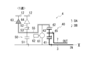
- FIG. 1 is a skeleton diagram showing a power transmission device.
- FIG. 2 is a fastening table of fastening elements in 1st to 3rd speeds.
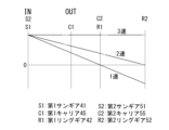
- FIG. 3 is a collinear diagram showing the number of rotations (rotational speed) of each element of the gear mechanism in the first to third speeds.
- FIG. 4 is a diagram showing a power transmission path in first speed.
- FIG. 5 is a diagram showing a power transmission path in second speed.
- FIG. 6 is a diagram showing a power transmission path in third speed.
- FIG. 7 is a skeleton diagram showing a gear mechanism according to modification 1.
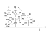
- FIG. 8 is a skeleton diagram showing a gear mechanism according to a second modification.
- a power transmission device is a device that includes a motor, which is a rotating electrical machine, and a power transmission mechanism that transmits the power of the motor to drive wheels.
- the power transmission mechanism includes, for example, a gear mechanism and/or a differential mechanism (differential gear mechanism).
- a second element (part, part, etc.) connected to a first element (part, part, etc.), a second element (part, part, etc.) connected downstream of the first element (part, part, etc.) , part, etc.), and a second element (part, part, etc.) connected upstream of the first element (part, part, etc.) means that the first element and the second element are connected so that power can be transmitted. It means there is.
- the power input side is upstream, and the power output side is downstream.
- the first element and the second element may be connected via another element (a clutch, another gear mechanism, etc.).
- “Overlapping when viewed from a predetermined direction” means that a plurality of elements are lined up in a predetermined direction, and has the same meaning as "overlapping in a predetermined direction.”
- the "predetermined direction” is, for example, an axial direction, a radial direction, a gravity direction, a vehicle running direction (vehicle forward direction, vehicle backward direction), or the like. If the drawings show that multiple elements (parts, parts, etc.) are lined up in a predetermined direction, a sentence explaining that they overlap when viewed from the predetermined direction shall be included in the description of the specification. It can be assumed that there is.
- the "predetermined direction” is, for example, an axial direction, a radial direction, a gravity direction, a vehicle running direction (vehicle forward direction, vehicle backward direction), or the like. If a drawing shows that multiple elements (parts, parts, etc.) are not lined up in a predetermined direction, a sentence explaining that they do not overlap when viewed from a predetermined direction shall be included in the description of the specification. It can be assumed that there is.
- the first element (component, section, etc.) is located between the second element (component, section, etc.) and the third element (component, section, etc.) when viewed from a predetermined direction" means In this case, it means that the first element can be observed to be between the second and third elements.
- the "predetermined direction" includes an axial direction, a radial direction, a direction of gravity, a vehicle running direction (vehicle forward direction, vehicle backward direction), and the like. For example, if the second element, first element, and third element are arranged in this order along the axial direction, the first element is located between the second element and the third element when viewed from the radial direction.
- the first element is shown to be between the second element and the third element when viewed from a predetermined direction
- the first element is shown to be between the second element and the third element when viewed from the predetermined direction. It can be assumed that there is a sentence explaining what is between the element and the third element.
- Axial direction means the axial direction of the rotating shaft of the parts that make up the device.
- Rotary direction means a direction perpendicular to the axis of rotation of the parts that make up the device.
- the parts are, for example, a motor, a gear mechanism, a differential gear mechanism, etc.
- FIG. 1 is a skeleton diagram showing a power transmission device 1.
- a power transmission device 1 includes a motor 2 (rotating electric machine) that is a power source that drives a vehicle.
- the power transmission device 1 includes an input shaft 3, a gear mechanism 4, an output shaft 7, a differential mechanism 9, and a drive shaft D as a power transmission mechanism that transmits the output rotation of the motor 2.
- the input shaft 3, gear mechanism 4, and output shaft 7 are arranged coaxially with the rotation axis X of the motor 2.
- the motor 2 is disposed on one side (the right side in the figure) of the power transmission device 1 in the direction of the rotation axis X, and the gear mechanism 4 is disposed on the other side (the left side in the figure).
- the motor 2 is connected to a gear mechanism 4 via an input shaft 3.
- the gear mechanism 4 is connected to a differential mechanism 9 via an output shaft 7.
- the rotation axis X extends along the vehicle width direction.
- the output shaft 7 is connected to the differential mechanism 9 via a reduction gear, a counter gear, etc. (not shown).
- the reduction gear, counter gear, etc. are provided along the vehicle longitudinal direction, which is a direction perpendicular to the rotation axis X.
- the differential mechanism 9 is connected to left and right drive wheels K, K of the vehicle via a drive shaft D.
- Drive shaft D extends along axis X5 parallel to rotation axis X.
- the motor 2 includes a rotor core 21 that is fitted onto the input shaft 3, and a stator core 25 that surrounds the outer periphery of the rotor core 21 at intervals.
- the input shaft 3 rotates together with the rotor core 21.
- the rotation input from the input shaft 3 is speed-changed by the gear mechanism 4 and output to the output shaft 7.
- the rotation output to the output shaft 7 is decelerated by a reduction gear, a counter gear, etc. (not shown), and is transmitted to the differential mechanism 9.
- the rotation transmitted to the differential mechanism 9 is transmitted to the left and right drive wheels K, K of the vehicle via the drive shaft D.
- the gear mechanism 4 is located downstream of the motor 2 in the power transmission path that transmits the rotational force of the motor 2.
- the differential mechanism 9 is located downstream of the gear mechanism 4 in the power transmission path.
- the output shaft 7 can have a hollow cylindrical shape, for example.
- An input shaft 3 extending from the motor 2 in the direction of the rotation axis X passes through the inside of the output shaft 7 and is connected to the gear mechanism 4 .
- the input shaft 3 and the output shaft 7 are provided so as to be relatively rotatable around the rotation axis X. When viewed from the radial direction of the rotation axis X, a portion of the input shaft 3 overlaps the output shaft 7.
- the power transmission device 1 has a structure in which the input shaft 3 extends from the motor 2 to the gear mechanism 4 side, and the output shaft 7 is folded back from the gear mechanism 4 to the motor 2 side.
- the output shaft 7 is arranged between the motor 2 located on one side of the power transmission device 1 in the direction of the rotation axis X, and the gear mechanism 4 located on the other side.
- the output shaft is arranged at the center of the power transmission device 1.
- a differential mechanism 9 connected to the output shaft 7 via a reduction gear, a counter gear, etc. (not shown) is arranged at the center of the drive shaft D in the axis X5 direction (vehicle width direction).
- the power transmission device 1 includes a motor case 11 that accommodates the motor 2, and a gear case 12 that accommodates the gear mechanism 4.
- the input shaft 3 and the output shaft 7 are supported by a motor case 11 or a gear case 12 via a bearing B.
- the differential mechanism 9 is housed in, for example, an axle case separate from the gear case 12.
- the gear mechanism 4 includes a first planetary gear mechanism 40 (hereinafter also simply referred to as the "first gear mechanism 40”) and a second planetary gear mechanism 50 (hereinafter also simply referred to as the "second gear mechanism 50").
- the first gear mechanism 40 and the second gear mechanism 50 are arranged side by side on the rotation axis X.
- the first gear mechanism 40 is arranged between the motor 2 and the second gear mechanism 50 in the rotation axis X direction.
- the first gear mechanism 40 and the second gear mechanism 50 overlap the motor 2 when viewed from the rotation axis X direction.
- the first gear mechanism 40 includes a first sun gear 41, a first carrier 45, and a first ring gear 42.
- the first sun gear 41 is fixed to the outer periphery of the input shaft 3 by, for example, spline fitting.
- the first carrier 45 includes a holding part 45a that holds the pinion gear 43, and a connecting part 45b that extends radially inward from the holding part 45a and connects to the output shaft 7.
- Pinion gear 43 meshes with the outer periphery of first sun gear 41 .
- the pinion gear 43 is provided so as to be rotatable in the circumferential direction around the rotation axis X, and also provided to be rotatable around each axis.
- the inner circumference of the first ring gear 42 meshes with the pinion gear 43.
- the first ring gear 42 is provided to be rotatable integrally with a second carrier 55, which will be described later.
- the first sun gear 41 fixed to the input shaft 3 is an input element
- the first carrier 45 connected to the output shaft 7 is an output element.
- the second gear mechanism 50 includes a second sun gear 51, a second carrier 55, and a second ring gear 52.
- the second sun gear 51 is fixed to the outer periphery of the input shaft 3 by, for example, spline fitting. That is, the input shaft 3 is provided so as to pass through the inner circumferences of the first sun gear 41 and the second sun gear 51 in the rotation axis X direction.
- the second carrier 55 has a holding part 55a that holds the pinion gear 53, a first connecting part 55b, and a second connecting part 55c.
- Pinion gear 53 meshes with the outer periphery of second sun gear 51 .
- the pinion gear 53 is provided so as to be rotatable in the circumferential direction around the rotation axis X, and also provided to be rotatable around each axis.
- the inner circumference of the second ring gear 52 meshes with the pinion gear 53.
- the first connecting portion 55b of the second carrier 55 is provided on the motor 2 side of the holding portion 55a in the rotation axis X direction.
- the first connecting portion 55b connects the holding portion 55a to the first ring gear 42 of the first gear mechanism 40.
- the second carrier 55 and the first ring gear 42 rotate integrally by the first connecting portion 55b.
- the second sun gear 51 fixed to the input shaft 3 is an input element
- the second carrier 55 connected to the first ring gear 42 of the first gear mechanism 40 is an output element.
- a clutch 61 (third fastening element) is provided on the inner diameter side of the first connecting portion 55b.
- An input end 61a of the clutch 61 is fixed to the input shaft 3, and an output end 61b is fixed to the first connection portion 55b of the second carrier 55.
- the first sun gear 41 is fixed to the input shaft 3, and the first ring gear 42 is connected to the first connecting portion 55b. Therefore, the first sun gear 41 and the first ring gear 42 are connected to the clutch 61 via the input shaft 3 and the first connecting portion 55b.
- An electric actuator 62 is connected to the clutch 61 .
- the clutch 61 and the electric actuator 62 are arranged between the first gear mechanism 40 and the second gear mechanism 50 in the direction of the rotation axis X.
- the clutch 61 and the electric actuator 62 are arranged at positions overlapping the first gear mechanism 40 and the second gear mechanism 50 in the rotation axis X direction.
- the clutch 61 is operated by an electric actuator 62 and is switched between a engaged state and a released state.
- the operation of the clutch 61 by the electric actuator 62 is controlled by a control device (not shown).
- a control device not shown.
- the clutch 61 When the clutch 61 is in the engaged state, the first connection portion 55b between the input shaft 3 and the second carrier 55 is engaged. As a result, the first sun gear 41, second sun gear 51, second carrier 55, and first ring gear 42 fixed to the input shaft 3 rotate integrally.
- the clutch 61 functions as a direct clutch for matching the rotational speeds of the input shaft 3 and the output shaft 7.
- the second connecting portion 55c of the second carrier 55 is provided on the side opposite to the first connecting portion 55b in the rotation axis X direction of the holding portion 55a.
- the second connecting portion 55c connects the holding portion 55a to a selectable one-way clutch 63 (hereinafter also referred to as "SOWC 63"), which is a first fastening element.
- SOWC 63 selectable one-way clutch 63
- the second carrier 55 is supported by the gear case 12 (first fixed element) via the SOWC 63.
- the SOWC 63 is operated by an actuator (not shown) and is switched between a fastened state, a released state, and an engaged state.
- the fastened state the second carrier 55 and the first ring gear 42 connected to the second carrier 55 are fixed to the gear case 12 in a non-rotatable manner.
- the released state the second carrier 55 and the first ring gear 42 are rotatable relative to the gear case 12 in either one direction or the other direction.
- the engaged state the second carrier 55 and the first ring gear 42 are rotatable in only one direction relative to the gear case 12.
- the outer periphery of the second ring gear 52 is connected to a selectable one-way clutch 64 (hereinafter also referred to as "SOWC 64"), which is a second fastening element.
- SOWC 64 selectable one-way clutch 64
- the second ring gear 52 is supported by the gear case 12 (second fixed element) via the SOWC 64.
- the SOWC 64 is operated by an actuator (not shown) and is switched between a fastened state, a released state, and an engaged state. In the fastened state, the second ring gear 52 is fixed to the gear case 12 in a non-rotatable manner. In the released state, the second ring gear 52 is rotatable relative to the gear case 12 in either one direction or the other direction. In the engaged state, the second ring gear 52 can rotate only in one direction with respect to the gear case 12.
- the operation of the SOWCs 63 and 64 by the actuators is controlled by a control device (not shown).
- the SOWCs 63 and 64 may be provided with a waiting mechanism composed of, for example, a spring or the like.
- the waiting mechanism is a mechanism that accumulates thrust applied from the actuator.
- the SOWCs 63 and 64 can be quickly switched between a released state, a fastened state, and an engaged state by a waiting mechanism.
- the gear ratio of the first gear mechanism 40 is set to be larger than the gear ratio of the second gear mechanism 50.
- a planetary gear mechanism the smaller the value obtained by dividing the number of teeth of the sun gear by the number of teeth of the ring gear ( ⁇ value), the larger the gear ratio becomes. That is, the ⁇ value of the first gear mechanism 40 (the number of teeth of the first sun gear 41/the number of teeth of the first ring gear 42) is the ⁇ value of the second gear mechanism 50 (the number of teeth of the second sun gear 51/the number of teeth of the second ring gear 42). (number of teeth of gear 52).
- the gear mechanism 4 has a first gear, a second gear, and a third gear as three gears with different gear ratios (output rotational speed/input rotational speed). Switching to each gear stage is performed by operating the SOWCs 63 and 64 and the clutch 61.
- first gear “second gear,” and “third gear” are also simply referred to as “first gear,” “second gear,” and “third gear.”
- FIG. 2 is an engagement table of engagement elements (SOWCs 63, 64 and clutch 61) in 1st to 3rd speeds.
- SOWCs 63, 64 and clutch 61 engagement elements
- FIG. 2 black circles are displayed in the column of elements in the fastened state.
- the column for the element in the released state is blank.
- FIG. 3 is a collinear chart showing the number of rotations (rotational speed) of each element of the gear mechanism 4 in the first to third speeds.
- 0 on each vertical axis means rotation speed 0.
- a value above 0 indicates rotation in one direction DA, which will be described later, and a value below 0 indicates rotation in the other direction DB, which will be described later.
- FIG. 1 engagement table of engagement elements
- FIG. 2 black circles are displayed in the column of elements in the fastened state.
- the column for the element in the released state is blank.
- FIG. 3 is a collinear chart showing the number of rotations (rotational speed) of each element of the gear mechanism 4
- FIG. 4 is a diagram showing a power transmission path in first speed.
- FIG. 5 is a diagram showing a power transmission path in second speed.
- FIG. 6 is a diagram showing a power transmission path in third speed.
- the power transmission path is shown by a thick line.
- elements in a released state are shown by broken lines, and elements in a fastened state are shown by cross hatching.
- elements that are fixed in a non-rotatable manner in the first gear mechanism 40 and the second gear mechanism 50 are shown with hatching.
- the rotation speeds of the first sun gear 41 and the second sun gear 51 correspond to the input rotation speed (IN) from the input shaft 3 to the gear mechanism 4.
- the rotation speed of the first carrier 45 corresponds to the output rotation speed (OUT) from the gear mechanism 4 to the output shaft 7.
- the first gear gear ratio (OUT/IN) is set to be the smallest, and the third gear gear ratio is set to be the largest.
- the gear ratio of 2nd speed is set larger than that of 1st speed and smaller than that of 3rd speed.
- the third speed is set to a gear ratio of 1 where the input rotational speed and the output rotational speed match.
- the SOWC 63 is in the engaged state, the SOWC 64 is in the released state, and the clutch 61 is in the released state.
- the input shaft 3 rotates in one direction DA around the rotation axis X, as shown in FIG.
- One-way DA means the direction of rotation when the vehicle is traveling forward.
- the unidirectional DA may be, for example, counterclockwise.
- the other direction DB is a clockwise direction when the one direction DA is counterclockwise.
- the second ring gear 52 idles in the other direction DB due to the rotation of the pinion gear 53. In this way, in the first speed, the second carrier 55 and the first ring gear 42 are fixed, so the rotation input to the second sun gear 51 of the second gear mechanism 50 is not output to the first gear mechanism 40. .
- the first sun gear 41 rotates in one direction DA
- the first ring gear 42 is fixed so as not to rotate.
- the pinion gear 43 that meshes with the first sun gear 41 and the first ring gear 42 rotates in the other direction DB while revolving in one direction DA.
- the revolution of the pinion gear 43 causes the first carrier 45 to rotate in one direction DA.
- the rotation of the first carrier 45 is output to the output shaft 7.
- the SOWC 63 in second speed, the SOWC 63 is in a released state, the SOWC 64 is in an engaged state, and the clutch 61 is in a released state.
- the first sun gear 41 of the first gear mechanism 40 and the second sun gear 51 of the second gear mechanism 50 rotate integrally with the input shaft 3 in one direction DA.
- the second ring gear 52 of the second gear mechanism 50 is fixed to the gear case 12 in a non-rotatable manner.
- the second sun gear 51 that rotates in one direction DA and the pinion gear 53 that meshes with the fixed second ring gear 52 rotate in the other direction DB while revolving in one direction DA.
- the second carrier 55 rotates in one direction DA due to the revolution of the pinion gear 53.
- the first ring gear 42 of the first gear mechanism 40 which is connected to the second carrier 55, also rotates in one direction DA. That is, the rotation output from the second carrier 55 of the second gear mechanism 50 is input to the first ring gear 42 of the first gear mechanism 40.
- the rotation input to the first ring gear 42 is shifted by a small gear ratio of the second gear mechanism 50. As shown in FIG. 3, the rotation speed of the first ring gear 42 is lower than the rotation speed of the first sun gear 41.
- the pinion gear 43 rotates in one direction DA while rotating in the other direction DB.
- the first carrier 45 rotates in one direction DA due to the revolution of the pinion gear 43.
- the rotation of the first carrier 45 is output to the output shaft 7.
- the rotation reduced by the second gear mechanism 50 is input to the first ring gear 42 of the first gear mechanism 40 via the second carrier 55, so the first ring gear 42 , is rotating at a speed lower than the input rotation speed.
- the gear ratio (OUT/IN) is larger in the second gear than in the first gear, where the first ring gear 42 is fixed and does not rotate.
- the output rotational speed of the second speed is higher than the output rotational speed of the first speed, and lower than the output rotational speed that is the same as the input rotational speed of the third speed.
- the SOWC 63 may be in an engaged state instead of being in a released state. In this case, the second carrier 55 and the first ring gear 42 can only rotate in one direction DA.
- the SOWC 63 and SOWC 64 are in the released state, and the clutch 61 is in the engaged state.
- the first sun gear 41 of the first gear mechanism 40 and the second sun gear 51 of the gear mechanism 4 rotate integrally with the input shaft 3 in one direction DA.
- the second carrier 55 of the second gear mechanism 50 is directly coupled to the input shaft 3.
- the clutch 61 which is a direct clutch.
- the first sun gear 41 and the first ring gear 42 of the first gear mechanism 40 rotate in one direction DA at the same rotational speed as the input shaft 3.
- the pinion gear 43 that meshes with the first sun gear 41 and the first ring gear 42 does not rotate, but revolves in one direction DA.
- the first carrier 45 rotates in one direction DA at the same rotational speed as the input shaft 3 due to the revolution of the pinion gear 43.
- the rotation of the first carrier 45 is output to the output shaft 7.
- the second carrier 55 of the second gear mechanism 50 is connected to the second sun gear 51 fixed to the input shaft 3 by a clutch 61. Thereby, the second sun gear 51 and the second carrier 55 rotate in one direction DA at the same rotational speed as the input shaft 3.
- the second ring gear 52 that meshes with the pinion gear 53 held by the second carrier 55 also rotates in one direction DA at the same rotational speed as the input shaft 3. That is, in the third speed, all six elements of the first gear mechanism 40 and the second gear mechanism 50 rotate at the same rotational speed as the input shaft 3.
- the clutch 61 functions as a direct coupling clutch that equalizes the rotational speeds of the input shaft 3 and the output shaft 7.
- the first ring gear 42 has the same rotational speed as the input shaft 3, so the gear ratio is 1, which is the largest.
- the output rotation speed of the third speed, which matches the input rotation speed, is the highest among the first to third speeds.
- the SOWCs 63 and 64 may be in an engaged state instead of being in a released state.
- the second carrier 55 and the second ring gear 52 can only rotate in one direction DA.
- a large torque is required to accelerate the vehicle.
- the first sun gear 41 of the first gear mechanism 40 is an input element
- the first carrier 45 is an output element
- the first ring gear 42 is fixed. This allows the reduction ratio in the first speed to be increased and the output torque to be increased. By increasing the reduction ratio and increasing the torque, the output of the motor 2 can be reduced.
- the clutch 61 is engaged to set the gear ratio 1 in which all elements of the first gear mechanism 40 and the second gear mechanism 50 rotate at the same rotational speed.
- the first speed is directly switched to the third speed without providing the second speed.
- the first ring gear 42 and the second carrier 55 are not rotating.
- the second ring gear 52 rotates in the other direction DB opposite to the one direction DA, which is the rotation direction of the input shaft 3. If the clutch 61 is engaged in a state where the difference in the rotational speed of each element of the gear mechanism 4 is large as described above, the shock at the time of engagement will be large. Although it is possible to engage the clutch 61 after reducing the difference in rotational speed, in that case, it takes time to engage the clutch 61.
- a second speed which is a middle gear
- the first gear which is the lowest gear
- the third gear which is the highest gear.
- the output end 61b of the clutch 61 can also be connected to the second ring gear 52 of the second gear mechanism 50.
- the second ring gear 52 is not rotating because it is fixed by the SOWC 64 (see FIG. 3). Therefore, there is a large difference in rotational speed between the second ring gear 52 and the input shaft 3 to which the input end 61a of the clutch 61 is connected, and it is difficult to reduce the shock when the clutch 61 is engaged.
- the first ring gear 42 of the first gear mechanism 40 is rotating in the second speed, the difference in rotational speed with the input shaft 3 is small. Thereby, the shock when the clutch 61 is engaged can be further reduced, and the engagement time of the clutch 61 can also be appropriately set.
- the torque sharing ratio of SOWC63 engaged in 1st gear was 2.174 as one of the appropriate tuning ranges
- the torque sharing ratio of SOWC63 engaged in 2nd gear was 2.174.
- the torque sharing ratio was 0.792.
- the torque sharing ratio of SOWC63 and SOWC64 in one of the above tuning ranges can be evaluated as a small value compared to general standards. That is, the skeleton according to one aspect of the present invention has the potential to reduce the burden on the SOWC 63 and SOWC 64 in the tuned skeleton.
- a fastening element with high strength is usually selected. In that case, the size of the fastening element increases and the cost increases. Note that there is a technical background that if even one difference in the connection relationship between each element in the skeleton occurs, the torque sharing ratio in the tuning result will change significantly. In view of this technical background, a skeleton according to one aspect of the present invention that can reduce the burden on fastening elements in a tuned skeleton can be evaluated as a good skeleton.
- the power transmission device 1 includes a first planetary gear mechanism 40 and a second planetary gear mechanism 50.
- the first planetary gear mechanism 40 includes a first sun gear 41 connected to the input shaft 3 , a first carrier 45 connected to the output shaft 7 , and a first ring gear 42 .
- the second planetary gear mechanism 50 includes a second sun gear 51 connected to the input shaft 3, and a second carrier 55 connected to the gear case 12 (first fixing element) via the SOWC 63 (first fastening element). It has a second ring gear 52 connected to the gear case 12 (second fixing element) via the SOWC 64 (second fastening element).
- the first planetary gear mechanism 40 and the second planetary gear mechanism 50 are connected by a first ring gear 42 and a second carrier 55.
- the first connecting portion 55b of the second carrier 55 which is the output element of the second planetary gear mechanism 50, is connected to the first ring gear 42.
- the first sun gear 41 and the first ring gear 42 are connected by a clutch 61 (third engagement element).
- the input end 61a of the clutch 61 is fixed to the input shaft 3, and the output end 61b is fixed to the first connection portion 55b of the second carrier 55.
- a first sun gear 41 is fixed to the input shaft 3, and the first connecting portion 55b is connected to the first ring gear 42. Therefore, the first sun gear 41 and the first ring gear 42 are connected to the clutch 61 via the input shaft 3 and the first connecting portion 55b.
- one aspect of the present invention is such a configuration that the first gear stage (speed ratio: small) to which the first ring gear 42 is fixed, and the first gear position where the first ring gear 42 is integrated with the input shaft 3.
- a second gear ratio (medium gear ratio) can be set between the rotating third gear ratio (large gear ratio).
- the clutch 61 is not attached to the second ring gear 52 of the second planetary gear mechanism 50 that is fixed in the second gear, but rather to the first ring gear 42 that is rotating in the second gear. connected to.
- the third gear stage four of the six elements of the first planetary gear mechanism 40 and the second planetary gear mechanism 50, the first sun gear 41, the second sun gear 51, the second carrier 55, and the first ring gear 42, are The two elements can be restrained by the clutch 61. This improves rotational stability when all elements of the first planetary gear mechanism 40 and the second planetary gear mechanism 50 are rotated together in the third gear stage.
- the gear case 12 is used as the first fixing element and the second fixing element
- the present invention is not limited to this embodiment. At least one of the first fixing element and the second fixing element may be a fixing member provided separately from the gear case 12.
- the value ( ⁇ value) obtained by dividing the number of teeth of the first sun gear 41 of the first planetary gear mechanism 40 by the number of teeth of the first ring gear 42 is the number of teeth of the second sun gear 51 of the second planetary gear mechanism 50. divided by the number of teeth of the second ring gear 52 ( ⁇ value).
- the smaller the ⁇ value the larger the gear ratio. That is, the gear ratio of the first planetary gear mechanism 40 is larger than the gear ratio of the second planetary gear mechanism 50.
- the gear ratio is decreased in the first gear stage where the first ring gear 42 is fixed, and the output torque from the gear mechanism 4 to the output shaft 7 is increased. I can do it.
- At least one of the first engagement element and the second engagement element may be a selectable one-way clutch.
- a selectable one-way clutch does not generate drag resistance like a multi-disc clutch or a band brake, so it can reduce friction when engaged.
- the selectable one-way clutch includes a waiting mechanism that accumulates the thrust applied from the actuator, it can quickly switch between a released state, a fastened state, and an engaged state. Thereby, the power transmission device 1 can improve controllability.
- both the first engagement element and the second engagement element are selectable one-way clutches 63 and 64
- the present invention is not limited to this embodiment.
- Either one of the first engagement element and the second engagement element may be a selectable one-way clutch, and the remaining may be other engagement elements such as a multi-disc clutch.
- the clutch 61 can be operated by the electric actuator 62.
- the responsiveness of the clutch 61 can be improved. Further, when a hydraulic actuator is employed, it is necessary to install an oil pump, oil, etc., and there is a concern that the weight of the power transmission device 1 will increase. By using the electric actuator 62, the weight of the power transmission device 1 can be reduced.
- the first planetary gear mechanism 40 is disposed between the motor 2 (rotating electric machine) and the second planetary gear mechanism 50 in the rotation axis X direction (axial direction) of the input shaft 3. I can do it.
- the output shaft 7 connected to the first carrier 45 of the first planetary gear mechanism 40 can be folded back toward the motor 2 side.
- the output shaft 7 has a folded structure, there is likely to be some extra space on the side opposite to the input shaft 3 and output shaft 7 in the direction of the rotation axis X.
- the input shaft 3 and the output shaft 7 partially overlap in the radial direction, so that the axial length can be shortened.
- the output shaft 7 can be arranged at the center of the power transmission device 1 in the direction of the rotation axis X.
- the differential mechanism 9 connected to the output shaft 7 can be arranged at the center of the drive shaft D in the rotation axis X direction.
- the power transmission device 1 includes, for example, the electric actuator 62 at a position that overlaps the first planetary gear mechanism 40 and the second planetary gear mechanism 50 in the axial direction.
- the power transmission device 1 can reduce the increase in size in the radial direction.
- a space is likely to be created on the side opposite to the input shaft 3 and the output shaft 7 in the rotation axis X direction.
- the electric actuator 62 in this space, the space can be used effectively, which is advantageous for layout.
- FIG. 7 is a skeleton diagram showing the gear mechanism 4 according to the first modification. Since the overall configuration of the power transmission device 1 of Modification 1 is the same as that of the above-described embodiment, FIG. 7 shows only the gear mechanism 4.
- the SOWC 63 first fastening element
- the SOWC 63 may be provided on either the second carrier 55 or the first ring gear 42.
- the SOWC 63 which is the first fastening element, may be provided so as to be connected to the outer periphery of the first ring gear 42.
- the second connection portion 55c of the second carrier 55 may not be provided.
- the second carrier 55 is connected to the gear case 12 (first fixing element) via the SOWC 63 (first fastening element).
- the second carrier 55 is connected to the gear case 12 (first fixing element) via the first ring gear 42 and SOWC 63 (first fastening element).
- the second carrier 55 and the first ring gear 42 can be fixed non-rotatably by bringing the SOWC 63 into the engaged state in the first speed.
- the SOWC 63 (first fastening element) may be connected to the first connecting portion 55b of the second carrier 55.
- the second carrier 55 and the first ring gear 42 can be fixed non-rotatably by bringing the SOWC 63 into the engaged state in the first speed.
- FIG. 8 is a skeleton diagram showing a gear mechanism 4 according to a second modification. Since the overall configuration of the power transmission device 1 of Modification 2 is the same as that of the above-described embodiment, FIG. 8 shows only the gear mechanism 4.
- the input end 61a of the clutch 61 (third engagement element) is connected to the input shaft 3, and the output end 61b is connected to the first connection part 55b of the second carrier 55. It is not limited to this aspect.
- the clutch 61 which is the third engagement element, may be any clutch as long as it can connect the first sun gear 41 and the first ring gear 42 so as to be integrally rotatable in the third speed.
- the output end 61b of the clutch 61 may be connected to the second connection portion 55c of the second carrier 55.
- An input end 61a of the clutch 61 is fixed to the input shaft 3.
- a first sun gear 41 is fixed to the input shaft 3, and a second connecting portion 55c is connected to the first ring gear 42 via a holding portion 55a and a first connecting portion 55b. Therefore, also in Modification 1, the first sun gear 41 and the first ring gear 42 are connected to the clutch 61 (third fastening element).
- the clutch 61 by engaging the clutch 61 in the third speed, the four elements of the first sun gear 41, second sun gear 51, second carrier 55, and first ring gear 42 are restrained by the clutch 61 and rotate integrally. do.
- the input end 61a of the clutch 61 which is the third engagement element, may be connected to the first sun gear 41 or the second sun gear 51 instead of the input shaft 3.
- the output end 61b of the clutch 61 may be connected to the first ring gear 42.
- a clutch 61 or an electric actuator 62 is arranged on one side of the rotation axis X direction (axial direction) with the first planetary gear mechanism 40 and the second planetary gear mechanism 50 interposed therebetween. , on the other side, elements connected to the differential mechanism 9 and the motor 2 (see FIG. 1) are arranged.
- the clutch 61 or the electric actuator 62 is arranged so as to overlap the first planetary gear mechanism 40 or the second planetary gear mechanism 50 in the rotation axis X direction.
- a space is likely to be created on the side opposite to the input shaft 3 and the output shaft 7 in the rotation axis X direction.
- the space can be used effectively, which is advantageous for layout.
- an element connected to the differential mechanism 9 is further placed between the first planetary gear mechanism 40 or the second planetary gear mechanism 50 and the motor 2 so as to be sandwiched in the axial direction.
- the motor 2 and the gear mechanism 4 are arranged on both sides of the differential mechanism 9, so that the weight balance of the entire device can be improved.
- the improvement in weight balance is also effective in structures other than those shown in FIG. 8, Modification 2 is particularly suitable when the weight balance is improved in this way.
- the power transmission device 1 has the clutch 61 or the electric actuator 62 on the back side of the first planetary gear mechanism 40 or the second planetary gear mechanism 50, where it is easy to secure space, so that the layout can be improved. It will be advantageous.
- the configuration of the second modification shown in FIG. 8 is not a structure in which the clutch 61 or the electric actuator 62 is sandwiched between the two planetary gear mechanisms 40 and 50, for example, as in FIG. Therefore, the gap between the two planetary gear mechanisms 40 and 50 can be closed. This is advantageous because, for example, the degree of freedom in design can be increased in terms of layout and shaft support of the two planetary gear mechanisms 40 and 50.
- a device according to a certain aspect of the present invention is applied to a power transmission device 1 mounted on a vehicle, but the present invention is not limited to this aspect.
- a device according to an embodiment of the present invention can be applied to other than vehicles. Further, in the case where a plurality of examples and modifications are described in this embodiment, these may be arbitrarily combined.
Landscapes
- Engineering & Computer Science (AREA)
- General Engineering & Computer Science (AREA)
- Mechanical Engineering (AREA)
- Structure Of Transmissions (AREA)
Priority Applications (4)
| Application Number | Priority Date | Filing Date | Title |
|---|---|---|---|
| JP2024505897A JP7566449B2 (ja) | 2022-03-09 | 2022-11-29 | 装置 |
| EP22931026.3A EP4491905A4 (en) | 2022-03-09 | 2022-11-29 | DEVICE |
| US18/844,166 US20250180098A1 (en) | 2022-03-09 | 2022-11-29 | Device |
| CN202280093132.6A CN118742751A (zh) | 2022-03-09 | 2022-11-29 | 装置 |
Applications Claiming Priority (2)
| Application Number | Priority Date | Filing Date | Title |
|---|---|---|---|
| JP2022-035857 | 2022-03-09 | ||
| JP2022035857 | 2022-03-09 |
Publications (1)
| Publication Number | Publication Date |
|---|---|
| WO2023171054A1 true WO2023171054A1 (ja) | 2023-09-14 |
Family
ID=87936510
Family Applications (1)
| Application Number | Title | Priority Date | Filing Date |
|---|---|---|---|
| PCT/JP2022/044065 Ceased WO2023171054A1 (ja) | 2022-03-09 | 2022-11-29 | 装置 |
Country Status (5)
| Country | Link |
|---|---|
| US (1) | US20250180098A1 (https=) |
| EP (1) | EP4491905A4 (https=) |
| JP (1) | JP7566449B2 (https=) |
| CN (1) | CN118742751A (https=) |
| WO (1) | WO2023171054A1 (https=) |
Citations (4)
| Publication number | Priority date | Publication date | Assignee | Title |
|---|---|---|---|---|
| KR20130043581A (ko) * | 2011-10-20 | 2013-04-30 | 유로캅터 도이칠란트 게엠베하 | 가변 전송을 위한 유성 기어 |
| CN106979285A (zh) | 2017-05-19 | 2017-07-25 | 福建万润新能源科技有限公司 | 一种双齿圈干摩擦外控三挡变速器 |
| CN107178585A (zh) * | 2017-06-30 | 2017-09-19 | 贵州凯星液力传动机械有限公司 | 一种大功率液力变速传动装置 |
| CN109099131A (zh) * | 2018-08-30 | 2018-12-28 | 上海迪鲲机电科技有限公司 | 一种用于电动车的电驱动传动装置及控制方法 |
Family Cites Families (7)
| Publication number | Priority date | Publication date | Assignee | Title |
|---|---|---|---|---|
| JP2892056B2 (ja) * | 1989-11-15 | 1999-05-17 | アイシン・エィ・ダブリュ株式会社 | 自動変速機 |
| JPH1026211A (ja) * | 1996-07-11 | 1998-01-27 | Exedy Corp | 自動変速装置 |
| US6290044B1 (en) * | 2000-04-03 | 2001-09-18 | General Motors Corporation | Selectable one-way clutch assembly |
| US9005071B2 (en) * | 2012-01-27 | 2015-04-14 | Deere & Company | Flexible and scalable multi-ratio planetary transmission |
| WO2015108017A1 (ja) * | 2014-01-14 | 2015-07-23 | アイシン・エィ・ダブリュ株式会社 | 自動変速機 |
| DE102018117051A1 (de) * | 2018-07-13 | 2020-01-16 | Patrick Harms | Unter Last schaltbares Getriebe |
| CN111396516B (zh) * | 2020-06-02 | 2020-10-16 | 北京航空航天大学 | 一种用于电动汽车的行星齿轮变速装置 |
-
2022
- 2022-11-29 US US18/844,166 patent/US20250180098A1/en active Pending
- 2022-11-29 EP EP22931026.3A patent/EP4491905A4/en active Pending
- 2022-11-29 WO PCT/JP2022/044065 patent/WO2023171054A1/ja not_active Ceased
- 2022-11-29 JP JP2024505897A patent/JP7566449B2/ja active Active
- 2022-11-29 CN CN202280093132.6A patent/CN118742751A/zh active Pending
Patent Citations (4)
| Publication number | Priority date | Publication date | Assignee | Title |
|---|---|---|---|---|
| KR20130043581A (ko) * | 2011-10-20 | 2013-04-30 | 유로캅터 도이칠란트 게엠베하 | 가변 전송을 위한 유성 기어 |
| CN106979285A (zh) | 2017-05-19 | 2017-07-25 | 福建万润新能源科技有限公司 | 一种双齿圈干摩擦外控三挡变速器 |
| CN107178585A (zh) * | 2017-06-30 | 2017-09-19 | 贵州凯星液力传动机械有限公司 | 一种大功率液力变速传动装置 |
| CN109099131A (zh) * | 2018-08-30 | 2018-12-28 | 上海迪鲲机电科技有限公司 | 一种用于电动车的电驱动传动装置及控制方法 |
Non-Patent Citations (1)
| Title |
|---|
| See also references of EP4491905A4 |
Also Published As
| Publication number | Publication date |
|---|---|
| JP7566449B2 (ja) | 2024-10-15 |
| CN118742751A (zh) | 2024-10-01 |
| JPWO2023171054A1 (https=) | 2023-09-14 |
| EP4491905A1 (en) | 2025-01-15 |
| EP4491905A4 (en) | 2025-07-09 |
| US20250180098A1 (en) | 2025-06-05 |
Similar Documents
| Publication | Publication Date | Title |
|---|---|---|
| US10203028B2 (en) | Drive gear unit | |
| JP6156135B2 (ja) | ハイブリッド車両の駆動装置 | |
| CN108953499B (zh) | 齿轮传动装置 | |
| WO2019074118A1 (ja) | 車両用駆動装置 | |
| JP5218031B2 (ja) | 車両の駆動装置 | |
| JP2010052518A (ja) | ハイブリッド車両の駆動装置 | |
| WO2017142060A1 (ja) | 動力伝達装置 | |
| JP5062122B2 (ja) | 車両の駆動装置 | |
| WO2016175287A1 (ja) | 変速装置 | |
| WO2023171054A1 (ja) | 装置 | |
| JP2020190333A (ja) | 歯車伝動装置 | |
| JP7835312B2 (ja) | 車両用変速機 | |
| JP2021076203A (ja) | 減速装置 | |
| WO2024014129A1 (ja) | ユニット | |
| WO2024014120A1 (ja) | ユニット | |
| WO2024014122A1 (ja) | ユニット | |
| CN110901358A (zh) | 电桥驱动系统和车辆 | |
| WO2024014119A1 (ja) | ユニット | |
| WO2024014124A1 (ja) | ユニット | |
| WO2024014128A1 (ja) | ユニット | |
| WO2024062708A1 (ja) | ユニット | |
| WO2024014121A1 (ja) | ユニット | |
| WO2024014125A1 (ja) | ユニット | |
| WO2024014127A1 (ja) | ユニット | |
| JP2023067198A (ja) | トルクベクタリング装置 |
Legal Events
| Date | Code | Title | Description |
|---|---|---|---|
| 121 | Ep: the epo has been informed by wipo that ep was designated in this application |
Ref document number: 22931026 Country of ref document: EP Kind code of ref document: A1 |
|
| ENP | Entry into the national phase |
Ref document number: 2024505897 Country of ref document: JP Kind code of ref document: A |
|
| WWE | Wipo information: entry into national phase |
Ref document number: 202280093132.6 Country of ref document: CN |
|
| WWE | Wipo information: entry into national phase |
Ref document number: 18844166 Country of ref document: US |
|
| WWE | Wipo information: entry into national phase |
Ref document number: 2022931026 Country of ref document: EP |
|
| NENP | Non-entry into the national phase |
Ref country code: DE |
|
| ENP | Entry into the national phase |
Ref document number: 2022931026 Country of ref document: EP Effective date: 20241009 |
|
| WWP | Wipo information: published in national office |
Ref document number: 18844166 Country of ref document: US |