WO2023171054A1 - Device - Google Patents
Device Download PDFInfo
- Publication number
- WO2023171054A1 WO2023171054A1 PCT/JP2022/044065 JP2022044065W WO2023171054A1 WO 2023171054 A1 WO2023171054 A1 WO 2023171054A1 JP 2022044065 W JP2022044065 W JP 2022044065W WO 2023171054 A1 WO2023171054 A1 WO 2023171054A1
- Authority
- WO
- WIPO (PCT)
- Prior art keywords
- gear
- gear mechanism
- clutch
- carrier
- ring gear
- Prior art date
Links
Images


Classifications
-
- F—MECHANICAL ENGINEERING; LIGHTING; HEATING; WEAPONS; BLASTING
- F16—ENGINEERING ELEMENTS AND UNITS; GENERAL MEASURES FOR PRODUCING AND MAINTAINING EFFECTIVE FUNCTIONING OF MACHINES OR INSTALLATIONS; THERMAL INSULATION IN GENERAL
- F16H—GEARING
- F16H3/00—Toothed gearings for conveying rotary motion with variable gear ratio or for reversing rotary motion
- F16H3/44—Toothed gearings for conveying rotary motion with variable gear ratio or for reversing rotary motion using gears having orbital motion
- F16H3/46—Gearings having only two central gears, connected by orbital gears
-
- Y—GENERAL TAGGING OF NEW TECHNOLOGICAL DEVELOPMENTS; GENERAL TAGGING OF CROSS-SECTIONAL TECHNOLOGIES SPANNING OVER SEVERAL SECTIONS OF THE IPC; TECHNICAL SUBJECTS COVERED BY FORMER USPC CROSS-REFERENCE ART COLLECTIONS [XRACs] AND DIGESTS
- Y02—TECHNOLOGIES OR APPLICATIONS FOR MITIGATION OR ADAPTATION AGAINST CLIMATE CHANGE
- Y02T—CLIMATE CHANGE MITIGATION TECHNOLOGIES RELATED TO TRANSPORTATION
- Y02T10/00—Road transport of goods or passengers
- Y02T10/60—Other road transportation technologies with climate change mitigation effect
- Y02T10/62—Hybrid vehicles
Definitions
- the present invention relates to an apparatus.
- Patent Document 1 discloses a device including a gear mechanism that transmits power (rotational force) generated by a motor.
- the gear mechanism changes the speed of the rotation input from the motor via the input shaft, and outputs the rotation to the differential mechanism via the output shaft.
- the device includes a clutch (direct clutch) for equalizing the rotational speeds of the input shaft and the output shaft.
- the shock generated by the engagement will be large. By reducing the difference in rotational speed before engaging the clutch, the shock can be alleviated, but it will take longer to engage the clutch.
- An apparatus in an aspect of the present invention includes: a first planetary gear mechanism including a first sun gear connected to the input shaft, a first carrier connected to the output shaft, and a first ring gear; A second sun gear connected to the input shaft, a second carrier connected to the first fixing element via the first fastening element, and a second ring gear connected to the second fixing element via the second fastening element. and a second planetary gear mechanism, The first planetary gear mechanism and the second planetary gear mechanism are connected by the first ring gear and the second carrier, The first sun gear and the first ring gear are connected by a third fastening element.
- FIG. 1 is a skeleton diagram showing a power transmission device.
- FIG. 2 is a fastening table of fastening elements in 1st to 3rd speeds.
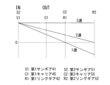
- FIG. 3 is a collinear diagram showing the number of rotations (rotational speed) of each element of the gear mechanism in the first to third speeds.
- FIG. 4 is a diagram showing a power transmission path in first speed.
- FIG. 5 is a diagram showing a power transmission path in second speed.
- FIG. 6 is a diagram showing a power transmission path in third speed.
- FIG. 7 is a skeleton diagram showing a gear mechanism according to modification 1.
- FIG. 8 is a skeleton diagram showing a gear mechanism according to a second modification.
- a power transmission device is a device that includes a motor, which is a rotating electrical machine, and a power transmission mechanism that transmits the power of the motor to drive wheels.
- the power transmission mechanism includes, for example, a gear mechanism and/or a differential mechanism (differential gear mechanism).
- a second element (part, part, etc.) connected to a first element (part, part, etc.), a second element (part, part, etc.) connected downstream of the first element (part, part, etc.) , part, etc.), and a second element (part, part, etc.) connected upstream of the first element (part, part, etc.) means that the first element and the second element are connected so that power can be transmitted. It means there is.
- the power input side is upstream, and the power output side is downstream.
- the first element and the second element may be connected via another element (a clutch, another gear mechanism, etc.).
- “Overlapping when viewed from a predetermined direction” means that a plurality of elements are lined up in a predetermined direction, and has the same meaning as "overlapping in a predetermined direction.”
- the "predetermined direction” is, for example, an axial direction, a radial direction, a gravity direction, a vehicle running direction (vehicle forward direction, vehicle backward direction), or the like. If the drawings show that multiple elements (parts, parts, etc.) are lined up in a predetermined direction, a sentence explaining that they overlap when viewed from the predetermined direction shall be included in the description of the specification. It can be assumed that there is.
- the "predetermined direction” is, for example, an axial direction, a radial direction, a gravity direction, a vehicle running direction (vehicle forward direction, vehicle backward direction), or the like. If a drawing shows that multiple elements (parts, parts, etc.) are not lined up in a predetermined direction, a sentence explaining that they do not overlap when viewed from a predetermined direction shall be included in the description of the specification. It can be assumed that there is.
- the first element (component, section, etc.) is located between the second element (component, section, etc.) and the third element (component, section, etc.) when viewed from a predetermined direction" means In this case, it means that the first element can be observed to be between the second and third elements.
- the "predetermined direction" includes an axial direction, a radial direction, a direction of gravity, a vehicle running direction (vehicle forward direction, vehicle backward direction), and the like. For example, if the second element, first element, and third element are arranged in this order along the axial direction, the first element is located between the second element and the third element when viewed from the radial direction.
- the first element is shown to be between the second element and the third element when viewed from a predetermined direction
- the first element is shown to be between the second element and the third element when viewed from the predetermined direction. It can be assumed that there is a sentence explaining what is between the element and the third element.
- Axial direction means the axial direction of the rotating shaft of the parts that make up the device.
- Rotary direction means a direction perpendicular to the axis of rotation of the parts that make up the device.
- the parts are, for example, a motor, a gear mechanism, a differential gear mechanism, etc.
- FIG. 1 is a skeleton diagram showing a power transmission device 1.
- a power transmission device 1 includes a motor 2 (rotating electric machine) that is a power source that drives a vehicle.
- the power transmission device 1 includes an input shaft 3, a gear mechanism 4, an output shaft 7, a differential mechanism 9, and a drive shaft D as a power transmission mechanism that transmits the output rotation of the motor 2.
- the input shaft 3, gear mechanism 4, and output shaft 7 are arranged coaxially with the rotation axis X of the motor 2.
- the motor 2 is disposed on one side (the right side in the figure) of the power transmission device 1 in the direction of the rotation axis X, and the gear mechanism 4 is disposed on the other side (the left side in the figure).
- the motor 2 is connected to a gear mechanism 4 via an input shaft 3.
- the gear mechanism 4 is connected to a differential mechanism 9 via an output shaft 7.
- the rotation axis X extends along the vehicle width direction.
- the output shaft 7 is connected to the differential mechanism 9 via a reduction gear, a counter gear, etc. (not shown).
- the reduction gear, counter gear, etc. are provided along the vehicle longitudinal direction, which is a direction perpendicular to the rotation axis X.
- the differential mechanism 9 is connected to left and right drive wheels K, K of the vehicle via a drive shaft D.
- Drive shaft D extends along axis X5 parallel to rotation axis X.
- the motor 2 includes a rotor core 21 that is fitted onto the input shaft 3, and a stator core 25 that surrounds the outer periphery of the rotor core 21 at intervals.
- the input shaft 3 rotates together with the rotor core 21.
- the rotation input from the input shaft 3 is speed-changed by the gear mechanism 4 and output to the output shaft 7.
- the rotation output to the output shaft 7 is decelerated by a reduction gear, a counter gear, etc. (not shown), and is transmitted to the differential mechanism 9.
- the rotation transmitted to the differential mechanism 9 is transmitted to the left and right drive wheels K, K of the vehicle via the drive shaft D.
- the gear mechanism 4 is located downstream of the motor 2 in the power transmission path that transmits the rotational force of the motor 2.
- the differential mechanism 9 is located downstream of the gear mechanism 4 in the power transmission path.
- the output shaft 7 can have a hollow cylindrical shape, for example.
- An input shaft 3 extending from the motor 2 in the direction of the rotation axis X passes through the inside of the output shaft 7 and is connected to the gear mechanism 4 .
- the input shaft 3 and the output shaft 7 are provided so as to be relatively rotatable around the rotation axis X. When viewed from the radial direction of the rotation axis X, a portion of the input shaft 3 overlaps the output shaft 7.
- the power transmission device 1 has a structure in which the input shaft 3 extends from the motor 2 to the gear mechanism 4 side, and the output shaft 7 is folded back from the gear mechanism 4 to the motor 2 side.
- the output shaft 7 is arranged between the motor 2 located on one side of the power transmission device 1 in the direction of the rotation axis X, and the gear mechanism 4 located on the other side.
- the output shaft is arranged at the center of the power transmission device 1.
- a differential mechanism 9 connected to the output shaft 7 via a reduction gear, a counter gear, etc. (not shown) is arranged at the center of the drive shaft D in the axis X5 direction (vehicle width direction).
- the power transmission device 1 includes a motor case 11 that accommodates the motor 2, and a gear case 12 that accommodates the gear mechanism 4.
- the input shaft 3 and the output shaft 7 are supported by a motor case 11 or a gear case 12 via a bearing B.
- the differential mechanism 9 is housed in, for example, an axle case separate from the gear case 12.
- the gear mechanism 4 includes a first planetary gear mechanism 40 (hereinafter also simply referred to as the "first gear mechanism 40”) and a second planetary gear mechanism 50 (hereinafter also simply referred to as the "second gear mechanism 50").
- the first gear mechanism 40 and the second gear mechanism 50 are arranged side by side on the rotation axis X.
- the first gear mechanism 40 is arranged between the motor 2 and the second gear mechanism 50 in the rotation axis X direction.
- the first gear mechanism 40 and the second gear mechanism 50 overlap the motor 2 when viewed from the rotation axis X direction.
- the first gear mechanism 40 includes a first sun gear 41, a first carrier 45, and a first ring gear 42.
- the first sun gear 41 is fixed to the outer periphery of the input shaft 3 by, for example, spline fitting.
- the first carrier 45 includes a holding part 45a that holds the pinion gear 43, and a connecting part 45b that extends radially inward from the holding part 45a and connects to the output shaft 7.
- Pinion gear 43 meshes with the outer periphery of first sun gear 41 .
- the pinion gear 43 is provided so as to be rotatable in the circumferential direction around the rotation axis X, and also provided to be rotatable around each axis.
- the inner circumference of the first ring gear 42 meshes with the pinion gear 43.
- the first ring gear 42 is provided to be rotatable integrally with a second carrier 55, which will be described later.
- the first sun gear 41 fixed to the input shaft 3 is an input element
- the first carrier 45 connected to the output shaft 7 is an output element.
- the second gear mechanism 50 includes a second sun gear 51, a second carrier 55, and a second ring gear 52.
- the second sun gear 51 is fixed to the outer periphery of the input shaft 3 by, for example, spline fitting. That is, the input shaft 3 is provided so as to pass through the inner circumferences of the first sun gear 41 and the second sun gear 51 in the rotation axis X direction.
- the second carrier 55 has a holding part 55a that holds the pinion gear 53, a first connecting part 55b, and a second connecting part 55c.
- Pinion gear 53 meshes with the outer periphery of second sun gear 51 .
- the pinion gear 53 is provided so as to be rotatable in the circumferential direction around the rotation axis X, and also provided to be rotatable around each axis.
- the inner circumference of the second ring gear 52 meshes with the pinion gear 53.
- the first connecting portion 55b of the second carrier 55 is provided on the motor 2 side of the holding portion 55a in the rotation axis X direction.
- the first connecting portion 55b connects the holding portion 55a to the first ring gear 42 of the first gear mechanism 40.
- the second carrier 55 and the first ring gear 42 rotate integrally by the first connecting portion 55b.
- the second sun gear 51 fixed to the input shaft 3 is an input element
- the second carrier 55 connected to the first ring gear 42 of the first gear mechanism 40 is an output element.
- a clutch 61 (third fastening element) is provided on the inner diameter side of the first connecting portion 55b.
- An input end 61a of the clutch 61 is fixed to the input shaft 3, and an output end 61b is fixed to the first connection portion 55b of the second carrier 55.
- the first sun gear 41 is fixed to the input shaft 3, and the first ring gear 42 is connected to the first connecting portion 55b. Therefore, the first sun gear 41 and the first ring gear 42 are connected to the clutch 61 via the input shaft 3 and the first connecting portion 55b.
- An electric actuator 62 is connected to the clutch 61 .
- the clutch 61 and the electric actuator 62 are arranged between the first gear mechanism 40 and the second gear mechanism 50 in the direction of the rotation axis X.
- the clutch 61 and the electric actuator 62 are arranged at positions overlapping the first gear mechanism 40 and the second gear mechanism 50 in the rotation axis X direction.
- the clutch 61 is operated by an electric actuator 62 and is switched between a engaged state and a released state.
- the operation of the clutch 61 by the electric actuator 62 is controlled by a control device (not shown).
- a control device not shown.
- the clutch 61 When the clutch 61 is in the engaged state, the first connection portion 55b between the input shaft 3 and the second carrier 55 is engaged. As a result, the first sun gear 41, second sun gear 51, second carrier 55, and first ring gear 42 fixed to the input shaft 3 rotate integrally.
- the clutch 61 functions as a direct clutch for matching the rotational speeds of the input shaft 3 and the output shaft 7.
- the second connecting portion 55c of the second carrier 55 is provided on the side opposite to the first connecting portion 55b in the rotation axis X direction of the holding portion 55a.
- the second connecting portion 55c connects the holding portion 55a to a selectable one-way clutch 63 (hereinafter also referred to as "SOWC 63"), which is a first fastening element.
- SOWC 63 selectable one-way clutch 63
- the second carrier 55 is supported by the gear case 12 (first fixed element) via the SOWC 63.
- the SOWC 63 is operated by an actuator (not shown) and is switched between a fastened state, a released state, and an engaged state.
- the fastened state the second carrier 55 and the first ring gear 42 connected to the second carrier 55 are fixed to the gear case 12 in a non-rotatable manner.
- the released state the second carrier 55 and the first ring gear 42 are rotatable relative to the gear case 12 in either one direction or the other direction.
- the engaged state the second carrier 55 and the first ring gear 42 are rotatable in only one direction relative to the gear case 12.
- the outer periphery of the second ring gear 52 is connected to a selectable one-way clutch 64 (hereinafter also referred to as "SOWC 64"), which is a second fastening element.
- SOWC 64 selectable one-way clutch 64
- the second ring gear 52 is supported by the gear case 12 (second fixed element) via the SOWC 64.
- the SOWC 64 is operated by an actuator (not shown) and is switched between a fastened state, a released state, and an engaged state. In the fastened state, the second ring gear 52 is fixed to the gear case 12 in a non-rotatable manner. In the released state, the second ring gear 52 is rotatable relative to the gear case 12 in either one direction or the other direction. In the engaged state, the second ring gear 52 can rotate only in one direction with respect to the gear case 12.
- the operation of the SOWCs 63 and 64 by the actuators is controlled by a control device (not shown).
- the SOWCs 63 and 64 may be provided with a waiting mechanism composed of, for example, a spring or the like.
- the waiting mechanism is a mechanism that accumulates thrust applied from the actuator.
- the SOWCs 63 and 64 can be quickly switched between a released state, a fastened state, and an engaged state by a waiting mechanism.
- the gear ratio of the first gear mechanism 40 is set to be larger than the gear ratio of the second gear mechanism 50.
- a planetary gear mechanism the smaller the value obtained by dividing the number of teeth of the sun gear by the number of teeth of the ring gear ( ⁇ value), the larger the gear ratio becomes. That is, the ⁇ value of the first gear mechanism 40 (the number of teeth of the first sun gear 41/the number of teeth of the first ring gear 42) is the ⁇ value of the second gear mechanism 50 (the number of teeth of the second sun gear 51/the number of teeth of the second ring gear 42). (number of teeth of gear 52).
- the gear mechanism 4 has a first gear, a second gear, and a third gear as three gears with different gear ratios (output rotational speed/input rotational speed). Switching to each gear stage is performed by operating the SOWCs 63 and 64 and the clutch 61.
- first gear “second gear,” and “third gear” are also simply referred to as “first gear,” “second gear,” and “third gear.”
- FIG. 2 is an engagement table of engagement elements (SOWCs 63, 64 and clutch 61) in 1st to 3rd speeds.
- SOWCs 63, 64 and clutch 61 engagement elements
- FIG. 2 black circles are displayed in the column of elements in the fastened state.
- the column for the element in the released state is blank.
- FIG. 3 is a collinear chart showing the number of rotations (rotational speed) of each element of the gear mechanism 4 in the first to third speeds.
- 0 on each vertical axis means rotation speed 0.
- a value above 0 indicates rotation in one direction DA, which will be described later, and a value below 0 indicates rotation in the other direction DB, which will be described later.
- FIG. 1 engagement table of engagement elements
- FIG. 2 black circles are displayed in the column of elements in the fastened state.
- the column for the element in the released state is blank.
- FIG. 3 is a collinear chart showing the number of rotations (rotational speed) of each element of the gear mechanism 4
- FIG. 4 is a diagram showing a power transmission path in first speed.
- FIG. 5 is a diagram showing a power transmission path in second speed.
- FIG. 6 is a diagram showing a power transmission path in third speed.
- the power transmission path is shown by a thick line.
- elements in a released state are shown by broken lines, and elements in a fastened state are shown by cross hatching.
- elements that are fixed in a non-rotatable manner in the first gear mechanism 40 and the second gear mechanism 50 are shown with hatching.
- the rotation speeds of the first sun gear 41 and the second sun gear 51 correspond to the input rotation speed (IN) from the input shaft 3 to the gear mechanism 4.
- the rotation speed of the first carrier 45 corresponds to the output rotation speed (OUT) from the gear mechanism 4 to the output shaft 7.
- the first gear gear ratio (OUT/IN) is set to be the smallest, and the third gear gear ratio is set to be the largest.
- the gear ratio of 2nd speed is set larger than that of 1st speed and smaller than that of 3rd speed.
- the third speed is set to a gear ratio of 1 where the input rotational speed and the output rotational speed match.
- the SOWC 63 is in the engaged state, the SOWC 64 is in the released state, and the clutch 61 is in the released state.
- the input shaft 3 rotates in one direction DA around the rotation axis X, as shown in FIG.
- One-way DA means the direction of rotation when the vehicle is traveling forward.
- the unidirectional DA may be, for example, counterclockwise.
- the other direction DB is a clockwise direction when the one direction DA is counterclockwise.
- the second ring gear 52 idles in the other direction DB due to the rotation of the pinion gear 53. In this way, in the first speed, the second carrier 55 and the first ring gear 42 are fixed, so the rotation input to the second sun gear 51 of the second gear mechanism 50 is not output to the first gear mechanism 40. .
- the first sun gear 41 rotates in one direction DA
- the first ring gear 42 is fixed so as not to rotate.
- the pinion gear 43 that meshes with the first sun gear 41 and the first ring gear 42 rotates in the other direction DB while revolving in one direction DA.
- the revolution of the pinion gear 43 causes the first carrier 45 to rotate in one direction DA.
- the rotation of the first carrier 45 is output to the output shaft 7.
- the SOWC 63 in second speed, the SOWC 63 is in a released state, the SOWC 64 is in an engaged state, and the clutch 61 is in a released state.
- the first sun gear 41 of the first gear mechanism 40 and the second sun gear 51 of the second gear mechanism 50 rotate integrally with the input shaft 3 in one direction DA.
- the second ring gear 52 of the second gear mechanism 50 is fixed to the gear case 12 in a non-rotatable manner.
- the second sun gear 51 that rotates in one direction DA and the pinion gear 53 that meshes with the fixed second ring gear 52 rotate in the other direction DB while revolving in one direction DA.
- the second carrier 55 rotates in one direction DA due to the revolution of the pinion gear 53.
- the first ring gear 42 of the first gear mechanism 40 which is connected to the second carrier 55, also rotates in one direction DA. That is, the rotation output from the second carrier 55 of the second gear mechanism 50 is input to the first ring gear 42 of the first gear mechanism 40.
- the rotation input to the first ring gear 42 is shifted by a small gear ratio of the second gear mechanism 50. As shown in FIG. 3, the rotation speed of the first ring gear 42 is lower than the rotation speed of the first sun gear 41.
- the pinion gear 43 rotates in one direction DA while rotating in the other direction DB.
- the first carrier 45 rotates in one direction DA due to the revolution of the pinion gear 43.
- the rotation of the first carrier 45 is output to the output shaft 7.
- the rotation reduced by the second gear mechanism 50 is input to the first ring gear 42 of the first gear mechanism 40 via the second carrier 55, so the first ring gear 42 , is rotating at a speed lower than the input rotation speed.
- the gear ratio (OUT/IN) is larger in the second gear than in the first gear, where the first ring gear 42 is fixed and does not rotate.
- the output rotational speed of the second speed is higher than the output rotational speed of the first speed, and lower than the output rotational speed that is the same as the input rotational speed of the third speed.
- the SOWC 63 may be in an engaged state instead of being in a released state. In this case, the second carrier 55 and the first ring gear 42 can only rotate in one direction DA.
- the SOWC 63 and SOWC 64 are in the released state, and the clutch 61 is in the engaged state.
- the first sun gear 41 of the first gear mechanism 40 and the second sun gear 51 of the gear mechanism 4 rotate integrally with the input shaft 3 in one direction DA.
- the second carrier 55 of the second gear mechanism 50 is directly coupled to the input shaft 3.
- the clutch 61 which is a direct clutch.
- the first sun gear 41 and the first ring gear 42 of the first gear mechanism 40 rotate in one direction DA at the same rotational speed as the input shaft 3.
- the pinion gear 43 that meshes with the first sun gear 41 and the first ring gear 42 does not rotate, but revolves in one direction DA.
- the first carrier 45 rotates in one direction DA at the same rotational speed as the input shaft 3 due to the revolution of the pinion gear 43.
- the rotation of the first carrier 45 is output to the output shaft 7.
- the second carrier 55 of the second gear mechanism 50 is connected to the second sun gear 51 fixed to the input shaft 3 by a clutch 61. Thereby, the second sun gear 51 and the second carrier 55 rotate in one direction DA at the same rotational speed as the input shaft 3.
- the second ring gear 52 that meshes with the pinion gear 53 held by the second carrier 55 also rotates in one direction DA at the same rotational speed as the input shaft 3. That is, in the third speed, all six elements of the first gear mechanism 40 and the second gear mechanism 50 rotate at the same rotational speed as the input shaft 3.
- the clutch 61 functions as a direct coupling clutch that equalizes the rotational speeds of the input shaft 3 and the output shaft 7.
- the first ring gear 42 has the same rotational speed as the input shaft 3, so the gear ratio is 1, which is the largest.
- the output rotation speed of the third speed, which matches the input rotation speed, is the highest among the first to third speeds.
- the SOWCs 63 and 64 may be in an engaged state instead of being in a released state.
- the second carrier 55 and the second ring gear 52 can only rotate in one direction DA.
- a large torque is required to accelerate the vehicle.
- the first sun gear 41 of the first gear mechanism 40 is an input element
- the first carrier 45 is an output element
- the first ring gear 42 is fixed. This allows the reduction ratio in the first speed to be increased and the output torque to be increased. By increasing the reduction ratio and increasing the torque, the output of the motor 2 can be reduced.
- the clutch 61 is engaged to set the gear ratio 1 in which all elements of the first gear mechanism 40 and the second gear mechanism 50 rotate at the same rotational speed.
- the first speed is directly switched to the third speed without providing the second speed.
- the first ring gear 42 and the second carrier 55 are not rotating.
- the second ring gear 52 rotates in the other direction DB opposite to the one direction DA, which is the rotation direction of the input shaft 3. If the clutch 61 is engaged in a state where the difference in the rotational speed of each element of the gear mechanism 4 is large as described above, the shock at the time of engagement will be large. Although it is possible to engage the clutch 61 after reducing the difference in rotational speed, in that case, it takes time to engage the clutch 61.
- a second speed which is a middle gear
- the first gear which is the lowest gear
- the third gear which is the highest gear.
- the output end 61b of the clutch 61 can also be connected to the second ring gear 52 of the second gear mechanism 50.
- the second ring gear 52 is not rotating because it is fixed by the SOWC 64 (see FIG. 3). Therefore, there is a large difference in rotational speed between the second ring gear 52 and the input shaft 3 to which the input end 61a of the clutch 61 is connected, and it is difficult to reduce the shock when the clutch 61 is engaged.
- the first ring gear 42 of the first gear mechanism 40 is rotating in the second speed, the difference in rotational speed with the input shaft 3 is small. Thereby, the shock when the clutch 61 is engaged can be further reduced, and the engagement time of the clutch 61 can also be appropriately set.
- the torque sharing ratio of SOWC63 engaged in 1st gear was 2.174 as one of the appropriate tuning ranges
- the torque sharing ratio of SOWC63 engaged in 2nd gear was 2.174.
- the torque sharing ratio was 0.792.
- the torque sharing ratio of SOWC63 and SOWC64 in one of the above tuning ranges can be evaluated as a small value compared to general standards. That is, the skeleton according to one aspect of the present invention has the potential to reduce the burden on the SOWC 63 and SOWC 64 in the tuned skeleton.
- a fastening element with high strength is usually selected. In that case, the size of the fastening element increases and the cost increases. Note that there is a technical background that if even one difference in the connection relationship between each element in the skeleton occurs, the torque sharing ratio in the tuning result will change significantly. In view of this technical background, a skeleton according to one aspect of the present invention that can reduce the burden on fastening elements in a tuned skeleton can be evaluated as a good skeleton.
- the power transmission device 1 includes a first planetary gear mechanism 40 and a second planetary gear mechanism 50.
- the first planetary gear mechanism 40 includes a first sun gear 41 connected to the input shaft 3 , a first carrier 45 connected to the output shaft 7 , and a first ring gear 42 .
- the second planetary gear mechanism 50 includes a second sun gear 51 connected to the input shaft 3, and a second carrier 55 connected to the gear case 12 (first fixing element) via the SOWC 63 (first fastening element). It has a second ring gear 52 connected to the gear case 12 (second fixing element) via the SOWC 64 (second fastening element).
- the first planetary gear mechanism 40 and the second planetary gear mechanism 50 are connected by a first ring gear 42 and a second carrier 55.
- the first connecting portion 55b of the second carrier 55 which is the output element of the second planetary gear mechanism 50, is connected to the first ring gear 42.
- the first sun gear 41 and the first ring gear 42 are connected by a clutch 61 (third engagement element).
- the input end 61a of the clutch 61 is fixed to the input shaft 3, and the output end 61b is fixed to the first connection portion 55b of the second carrier 55.
- a first sun gear 41 is fixed to the input shaft 3, and the first connecting portion 55b is connected to the first ring gear 42. Therefore, the first sun gear 41 and the first ring gear 42 are connected to the clutch 61 via the input shaft 3 and the first connecting portion 55b.
- one aspect of the present invention is such a configuration that the first gear stage (speed ratio: small) to which the first ring gear 42 is fixed, and the first gear position where the first ring gear 42 is integrated with the input shaft 3.
- a second gear ratio (medium gear ratio) can be set between the rotating third gear ratio (large gear ratio).
- the clutch 61 is not attached to the second ring gear 52 of the second planetary gear mechanism 50 that is fixed in the second gear, but rather to the first ring gear 42 that is rotating in the second gear. connected to.
- the third gear stage four of the six elements of the first planetary gear mechanism 40 and the second planetary gear mechanism 50, the first sun gear 41, the second sun gear 51, the second carrier 55, and the first ring gear 42, are The two elements can be restrained by the clutch 61. This improves rotational stability when all elements of the first planetary gear mechanism 40 and the second planetary gear mechanism 50 are rotated together in the third gear stage.
- the gear case 12 is used as the first fixing element and the second fixing element
- the present invention is not limited to this embodiment. At least one of the first fixing element and the second fixing element may be a fixing member provided separately from the gear case 12.
- the value ( ⁇ value) obtained by dividing the number of teeth of the first sun gear 41 of the first planetary gear mechanism 40 by the number of teeth of the first ring gear 42 is the number of teeth of the second sun gear 51 of the second planetary gear mechanism 50. divided by the number of teeth of the second ring gear 52 ( ⁇ value).
- the smaller the ⁇ value the larger the gear ratio. That is, the gear ratio of the first planetary gear mechanism 40 is larger than the gear ratio of the second planetary gear mechanism 50.
- the gear ratio is decreased in the first gear stage where the first ring gear 42 is fixed, and the output torque from the gear mechanism 4 to the output shaft 7 is increased. I can do it.
- At least one of the first engagement element and the second engagement element may be a selectable one-way clutch.
- a selectable one-way clutch does not generate drag resistance like a multi-disc clutch or a band brake, so it can reduce friction when engaged.
- the selectable one-way clutch includes a waiting mechanism that accumulates the thrust applied from the actuator, it can quickly switch between a released state, a fastened state, and an engaged state. Thereby, the power transmission device 1 can improve controllability.
- both the first engagement element and the second engagement element are selectable one-way clutches 63 and 64
- the present invention is not limited to this embodiment.
- Either one of the first engagement element and the second engagement element may be a selectable one-way clutch, and the remaining may be other engagement elements such as a multi-disc clutch.
- the clutch 61 can be operated by the electric actuator 62.
- the responsiveness of the clutch 61 can be improved. Further, when a hydraulic actuator is employed, it is necessary to install an oil pump, oil, etc., and there is a concern that the weight of the power transmission device 1 will increase. By using the electric actuator 62, the weight of the power transmission device 1 can be reduced.
- the first planetary gear mechanism 40 is disposed between the motor 2 (rotating electric machine) and the second planetary gear mechanism 50 in the rotation axis X direction (axial direction) of the input shaft 3. I can do it.
- the output shaft 7 connected to the first carrier 45 of the first planetary gear mechanism 40 can be folded back toward the motor 2 side.
- the output shaft 7 has a folded structure, there is likely to be some extra space on the side opposite to the input shaft 3 and output shaft 7 in the direction of the rotation axis X.
- the input shaft 3 and the output shaft 7 partially overlap in the radial direction, so that the axial length can be shortened.
- the output shaft 7 can be arranged at the center of the power transmission device 1 in the direction of the rotation axis X.
- the differential mechanism 9 connected to the output shaft 7 can be arranged at the center of the drive shaft D in the rotation axis X direction.
- the power transmission device 1 includes, for example, the electric actuator 62 at a position that overlaps the first planetary gear mechanism 40 and the second planetary gear mechanism 50 in the axial direction.
- the power transmission device 1 can reduce the increase in size in the radial direction.
- a space is likely to be created on the side opposite to the input shaft 3 and the output shaft 7 in the rotation axis X direction.
- the electric actuator 62 in this space, the space can be used effectively, which is advantageous for layout.
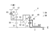
- FIG. 7 is a skeleton diagram showing the gear mechanism 4 according to the first modification. Since the overall configuration of the power transmission device 1 of Modification 1 is the same as that of the above-described embodiment, FIG. 7 shows only the gear mechanism 4.
- the SOWC 63 first fastening element
- the SOWC 63 may be provided on either the second carrier 55 or the first ring gear 42.
- the SOWC 63 which is the first fastening element, may be provided so as to be connected to the outer periphery of the first ring gear 42.
- the second connection portion 55c of the second carrier 55 may not be provided.
- the second carrier 55 is connected to the gear case 12 (first fixing element) via the SOWC 63 (first fastening element).
- the second carrier 55 is connected to the gear case 12 (first fixing element) via the first ring gear 42 and SOWC 63 (first fastening element).
- the second carrier 55 and the first ring gear 42 can be fixed non-rotatably by bringing the SOWC 63 into the engaged state in the first speed.
- the SOWC 63 (first fastening element) may be connected to the first connecting portion 55b of the second carrier 55.
- the second carrier 55 and the first ring gear 42 can be fixed non-rotatably by bringing the SOWC 63 into the engaged state in the first speed.
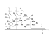
- FIG. 8 is a skeleton diagram showing a gear mechanism 4 according to a second modification. Since the overall configuration of the power transmission device 1 of Modification 2 is the same as that of the above-described embodiment, FIG. 8 shows only the gear mechanism 4.
- the input end 61a of the clutch 61 (third engagement element) is connected to the input shaft 3, and the output end 61b is connected to the first connection part 55b of the second carrier 55. It is not limited to this aspect.
- the clutch 61 which is the third engagement element, may be any clutch as long as it can connect the first sun gear 41 and the first ring gear 42 so as to be integrally rotatable in the third speed.
- the output end 61b of the clutch 61 may be connected to the second connection portion 55c of the second carrier 55.
- An input end 61a of the clutch 61 is fixed to the input shaft 3.
- a first sun gear 41 is fixed to the input shaft 3, and a second connecting portion 55c is connected to the first ring gear 42 via a holding portion 55a and a first connecting portion 55b. Therefore, also in Modification 1, the first sun gear 41 and the first ring gear 42 are connected to the clutch 61 (third fastening element).
- the clutch 61 by engaging the clutch 61 in the third speed, the four elements of the first sun gear 41, second sun gear 51, second carrier 55, and first ring gear 42 are restrained by the clutch 61 and rotate integrally. do.
- the input end 61a of the clutch 61 which is the third engagement element, may be connected to the first sun gear 41 or the second sun gear 51 instead of the input shaft 3.
- the output end 61b of the clutch 61 may be connected to the first ring gear 42.
- a clutch 61 or an electric actuator 62 is arranged on one side of the rotation axis X direction (axial direction) with the first planetary gear mechanism 40 and the second planetary gear mechanism 50 interposed therebetween. , on the other side, elements connected to the differential mechanism 9 and the motor 2 (see FIG. 1) are arranged.
- the clutch 61 or the electric actuator 62 is arranged so as to overlap the first planetary gear mechanism 40 or the second planetary gear mechanism 50 in the rotation axis X direction.
- a space is likely to be created on the side opposite to the input shaft 3 and the output shaft 7 in the rotation axis X direction.
- the space can be used effectively, which is advantageous for layout.
- an element connected to the differential mechanism 9 is further placed between the first planetary gear mechanism 40 or the second planetary gear mechanism 50 and the motor 2 so as to be sandwiched in the axial direction.
- the motor 2 and the gear mechanism 4 are arranged on both sides of the differential mechanism 9, so that the weight balance of the entire device can be improved.
- the improvement in weight balance is also effective in structures other than those shown in FIG. 8, Modification 2 is particularly suitable when the weight balance is improved in this way.
- the power transmission device 1 has the clutch 61 or the electric actuator 62 on the back side of the first planetary gear mechanism 40 or the second planetary gear mechanism 50, where it is easy to secure space, so that the layout can be improved. It will be advantageous.
- the configuration of the second modification shown in FIG. 8 is not a structure in which the clutch 61 or the electric actuator 62 is sandwiched between the two planetary gear mechanisms 40 and 50, for example, as in FIG. Therefore, the gap between the two planetary gear mechanisms 40 and 50 can be closed. This is advantageous because, for example, the degree of freedom in design can be increased in terms of layout and shaft support of the two planetary gear mechanisms 40 and 50.
- a device according to a certain aspect of the present invention is applied to a power transmission device 1 mounted on a vehicle, but the present invention is not limited to this aspect.
- a device according to an embodiment of the present invention can be applied to other than vehicles. Further, in the case where a plurality of examples and modifications are described in this embodiment, these may be arbitrarily combined.
Abstract
[Problem] To suitably set a time for causing clutches to engage while reducing shock when the clutches engage. [Solution] This device has: a first planetary gear mechanism that has a first sun gear connected to an input shaft, a first carrier connected to an output shaft, and a first ring gear; and a second planetary gear mechanism that has a second sun gear connected to the input shaft, a second carrier connected to a first fixing element via a first engaging element, and a second ring gear connected to a second fixing element via a second engaging element. The first planetary gear mechanism and the second planetary gear mechanism are connected by the first ring gear and the second carrier, and the first sun gear and the first ring gear are connected by a third engaging element.
Description
本発明は、装置に関する。
The present invention relates to an apparatus.
特許文献1は、モータで発生する動力(回転力)を伝達する歯車機構を備えた装置を開示している。歯車機構は、入力軸を介してモータから入力された回転を変速し、出力軸を介して差動機構に出力する。装置は、入力軸と出力軸の回転速度を等しくするためのクラッチ(直結クラッチ)を備える。
Patent Document 1 discloses a device including a gear mechanism that transmits power (rotational force) generated by a motor. The gear mechanism changes the speed of the rotation input from the motor via the input shaft, and outputs the rotation to the differential mechanism via the output shaft. The device includes a clutch (direct clutch) for equalizing the rotational speeds of the input shaft and the output shaft.
入力軸と出力軸の回転速度の差が大きい状態でクラッチを締結すると、締結によって生じるショックが大きい。回転速度の差を小さくしてからクラッチを締結することでショックは緩和されるが、クラッチを締結するまでの時間が長くなる。
If the clutch is engaged when the difference in rotational speed between the input shaft and the output shaft is large, the shock generated by the engagement will be large. By reducing the difference in rotational speed before engaging the clutch, the shock can be alleviated, but it will take longer to engage the clutch.
装置において、クラッチを締結する際のショックを低減しつつ、クラッチを締結させる時間を適切に設定することが求められている。
In the device, it is required to appropriately set the time for engaging the clutch while reducing the shock when engaging the clutch.
本発明のある態様における装置は、
入力軸と接続される第1サンギアと、出力軸と接続される第1キャリアと、第1リングギアと、を有する第1遊星歯車機構と、
入力軸と接続される第2サンギアと、第1締結要素を介して第1固定要素と接続される第2キャリアと、第2締結要素を介して第2固定要素と接続される第2リングギアと、を有する第2遊星歯車機構と、を有し、
前記第1遊星歯車機構と前記第2遊星歯車機構とは、前記第1リングギアと前記第2キャリアとで接続され、
前記第1サンギアと前記第1リングギアとは、第3締結要素で接続される。 An apparatus in an aspect of the present invention includes:
a first planetary gear mechanism including a first sun gear connected to the input shaft, a first carrier connected to the output shaft, and a first ring gear;
A second sun gear connected to the input shaft, a second carrier connected to the first fixing element via the first fastening element, and a second ring gear connected to the second fixing element via the second fastening element. and a second planetary gear mechanism,
The first planetary gear mechanism and the second planetary gear mechanism are connected by the first ring gear and the second carrier,
The first sun gear and the first ring gear are connected by a third fastening element.
本発明のある態様によれば、第3締結要素であるクラッチを締結する際のショックを低減しつつ、クラッチを締結させる時間を適切に設定することができる。
According to an aspect of the present invention, it is possible to appropriately set the time for engaging the clutch while reducing the shock when engaging the clutch, which is the third engaging element.
以下の説明では、本発明のある態様における装置を、車両に搭載された動力伝達装置に適用する例を説明する。動力伝達装置は、回転電機であるモータと、モータの動力を駆動輪に伝達する動力伝達機構とを備えた装置である。動力伝達機構は、例えば、歯車機構および/または差動機構(差動歯車機構)を備える。
In the following description, an example will be described in which a device according to an aspect of the present invention is applied to a power transmission device mounted on a vehicle. A power transmission device is a device that includes a motor, which is a rotating electrical machine, and a power transmission mechanism that transmits the power of the motor to drive wheels. The power transmission mechanism includes, for example, a gear mechanism and/or a differential mechanism (differential gear mechanism).
なお、以下の説明において、第1要素(部品、部分等)に接続された第2要素(部品、部分等)、第1要素(部品、部分等)の下流に接続された第2要素(部品、部分等)、第1要素(部品、部分等)の上流に接続された第2要素(部品、部分等)と述べた場合、第1要素と第2要素とが動力伝達可能に接続されていることを意味する。動力の入力側が上流となり、動力の出力側が下流となる。また、第1要素と第2要素は、他の要素(クラッチ、他の歯車機構等)を介して接続されていても良い。
In the following description, a second element (part, part, etc.) connected to a first element (part, part, etc.), a second element (part, part, etc.) connected downstream of the first element (part, part, etc.) , part, etc.), and a second element (part, part, etc.) connected upstream of the first element (part, part, etc.) means that the first element and the second element are connected so that power can be transmitted. It means there is. The power input side is upstream, and the power output side is downstream. Further, the first element and the second element may be connected via another element (a clutch, another gear mechanism, etc.).
「所定方向から見てオーバーラップする」とは、所定方向に複数の要素が並んでいることを意味し、「所定方向にオーバーラップする」と記載する場合と同義である。「所定方向」は、例えば、軸方向、径方向、重力方向、車両走行方向(車両前進方向、車両後進方向)等である。
図面上において複数の要素(部品、部分等)が所定方向に並んでいることが図示されている場合は、明細書の説明において、所定方向から見てオーバーラップしていることを説明した文章があるとみなして良い。 "Overlapping when viewed from a predetermined direction" means that a plurality of elements are lined up in a predetermined direction, and has the same meaning as "overlapping in a predetermined direction." The "predetermined direction" is, for example, an axial direction, a radial direction, a gravity direction, a vehicle running direction (vehicle forward direction, vehicle backward direction), or the like.
If the drawings show that multiple elements (parts, parts, etc.) are lined up in a predetermined direction, a sentence explaining that they overlap when viewed from the predetermined direction shall be included in the description of the specification. It can be assumed that there is.
「所定方向から見てオーバーラップしていない」、「所定方向から見てオフセットしている」とは、所定方向に複数の要素が並んでいないことを意味し、「所定方向にオーバーラップしていない」、「所定方向にオフセットしている」と記載する場合と同義である。「所定方向」は、例えば、軸方向、径方向、重力方向、車両走行方向(車両前進方向、車両後進方向)等である。
図面上において複数の要素(部品、部分等)が所定方向に並んでいないことが図示されている場合は、明細書の説明において、所定方向から見てオーバーラップしていないことを説明した文章があるとみなして良い。 "They do not overlap when viewed from a given direction" and "they are offset when seen from a given direction" mean that multiple elements are not lined up in a given direction, and "they do not overlap in a given direction". This has the same meaning as "not present" or "offset in a predetermined direction." The "predetermined direction" is, for example, an axial direction, a radial direction, a gravity direction, a vehicle running direction (vehicle forward direction, vehicle backward direction), or the like.
If a drawing shows that multiple elements (parts, parts, etc.) are not lined up in a predetermined direction, a sentence explaining that they do not overlap when viewed from a predetermined direction shall be included in the description of the specification. It can be assumed that there is.
「所定方向から見て、第1要素(部品、部分等)は第2要素(部品、部分等)と第3要素(部品、部分等)との間に位置する」とは、所定方向から観察した場合において、第1要素が第2要素と第3要素との間にあることが観察できることを意味する。「所定方向」とは、軸方向、径方向、重力方向、車両走行方向(車両前進方向、車両後進方向)等である。
例えば、第2要素と第1要素と第3要素とが、この順で軸方向に沿って並んでいる場合は、径方向から見て、第1要素は第2要素と第3要素との間に位置しているといえる。図面上において、所定方向から見て第1要素が第2要素と第3要素との間にあることが図示されている場合は、明細書の説明において所定方向から見て第1要素が第2要素と第3要素との間にあることを説明した文章があるとみなして良い。 "The first element (component, section, etc.) is located between the second element (component, section, etc.) and the third element (component, section, etc.) when viewed from a predetermined direction" means In this case, it means that the first element can be observed to be between the second and third elements. The "predetermined direction" includes an axial direction, a radial direction, a direction of gravity, a vehicle running direction (vehicle forward direction, vehicle backward direction), and the like.
For example, if the second element, first element, and third element are arranged in this order along the axial direction, the first element is located between the second element and the third element when viewed from the radial direction. It can be said that it is located in In the drawings, if the first element is shown to be between the second element and the third element when viewed from a predetermined direction, in the description of the specification, the first element is shown to be between the second element and the third element when viewed from the predetermined direction. It can be assumed that there is a sentence explaining what is between the element and the third element.
軸方向から見て、2つの要素(部品、部分等)がオーバーラップするとき、2つの要素は同軸である。
When two elements (parts, sections, etc.) overlap when viewed from the axial direction, the two elements are coaxial.
「軸方向」とは、装置を構成する部品の回転軸の軸方向を意味する。「径方向」とは、装置を構成する部品の回転軸に直交する方向を意味する。部品は、例えば、モータ、歯車機構、差動歯車機構等である。
"Axial direction" means the axial direction of the rotating shaft of the parts that make up the device. "Radial direction" means a direction perpendicular to the axis of rotation of the parts that make up the device. The parts are, for example, a motor, a gear mechanism, a differential gear mechanism, etc.
図1は、動力伝達装置1を示すスケルトン図である。
図1に示すように、動力伝達装置1は、車両を駆動する動力源であるモータ2(回転電機)を有する。動力伝達装置1は、モータ2の出力回転を伝達する動力伝達機構として、入力軸3、歯車機構4、出力軸7、差動機構9、ドライブシャフトDを備える。 FIG. 1 is a skeleton diagram showing a power transmission device 1. FIG.
As shown in FIG. 1, a power transmission device 1 includes a motor 2 (rotating electric machine) that is a power source that drives a vehicle. The power transmission device 1 includes aninput shaft 3, a gear mechanism 4, an output shaft 7, a differential mechanism 9, and a drive shaft D as a power transmission mechanism that transmits the output rotation of the motor 2.
図1に示すように、動力伝達装置1は、車両を駆動する動力源であるモータ2(回転電機)を有する。動力伝達装置1は、モータ2の出力回転を伝達する動力伝達機構として、入力軸3、歯車機構4、出力軸7、差動機構9、ドライブシャフトDを備える。 FIG. 1 is a skeleton diagram showing a power transmission device 1. FIG.
As shown in FIG. 1, a power transmission device 1 includes a motor 2 (rotating electric machine) that is a power source that drives a vehicle. The power transmission device 1 includes an
入力軸3、歯車機構4、出力軸7は、モータ2の回転軸Xと同軸上に配置されている。動力伝達装置1の回転軸X方向における一方側(図中、右側)にモータ2が配置され、他方側(図中、左側)に歯車機構4が配置される。モータ2は、入力軸3を介して歯車機構4に接続されている。歯車機構4は、出力軸7を介して差動機構9に接続されている。回転軸Xは、車幅方向に沿って延びる。
The input shaft 3, gear mechanism 4, and output shaft 7 are arranged coaxially with the rotation axis X of the motor 2. The motor 2 is disposed on one side (the right side in the figure) of the power transmission device 1 in the direction of the rotation axis X, and the gear mechanism 4 is disposed on the other side (the left side in the figure). The motor 2 is connected to a gear mechanism 4 via an input shaft 3. The gear mechanism 4 is connected to a differential mechanism 9 via an output shaft 7. The rotation axis X extends along the vehicle width direction.
出力軸7は、リダクションギア、カウンタギア等(不図示)を介して差動機構9に接続されている。リダクションギア、カウンタギア等は、回転軸Xと直交する方向である車両前後方向に沿って設けられる。
差動機構9は、ドライブシャフトDを介して、車両の左右の駆動輪K、Kに接続されている。ドライブシャフトDは、回転軸Xと平行な軸線X5に沿って延びる。 Theoutput shaft 7 is connected to the differential mechanism 9 via a reduction gear, a counter gear, etc. (not shown). The reduction gear, counter gear, etc. are provided along the vehicle longitudinal direction, which is a direction perpendicular to the rotation axis X.
Thedifferential mechanism 9 is connected to left and right drive wheels K, K of the vehicle via a drive shaft D. Drive shaft D extends along axis X5 parallel to rotation axis X.
差動機構9は、ドライブシャフトDを介して、車両の左右の駆動輪K、Kに接続されている。ドライブシャフトDは、回転軸Xと平行な軸線X5に沿って延びる。 The
The
モータ2は、入力軸3に外挿されたロータコア21と、ロータコア21の外周を間隔を空けて囲むステータコア25と、を有する。
モータ2が駆動されて、ロータコア21が回転軸X回りに回転すると、ロータコア21と一体に入力軸3が回転する。入力軸3から入力された回転は歯車機構4で変速され、出力軸7に出力される。出力軸7に出力された回転は、不図示のリダクションギア、カウンタギア等で減速され、差動機構9に伝達される。差動機構9に伝達された回転は、ドライブシャフトDを介して、車両の左右の駆動輪K、Kに伝達される。 Themotor 2 includes a rotor core 21 that is fitted onto the input shaft 3, and a stator core 25 that surrounds the outer periphery of the rotor core 21 at intervals.
When themotor 2 is driven and the rotor core 21 rotates around the rotation axis X, the input shaft 3 rotates together with the rotor core 21. The rotation input from the input shaft 3 is speed-changed by the gear mechanism 4 and output to the output shaft 7. The rotation output to the output shaft 7 is decelerated by a reduction gear, a counter gear, etc. (not shown), and is transmitted to the differential mechanism 9. The rotation transmitted to the differential mechanism 9 is transmitted to the left and right drive wheels K, K of the vehicle via the drive shaft D.
モータ2が駆動されて、ロータコア21が回転軸X回りに回転すると、ロータコア21と一体に入力軸3が回転する。入力軸3から入力された回転は歯車機構4で変速され、出力軸7に出力される。出力軸7に出力された回転は、不図示のリダクションギア、カウンタギア等で減速され、差動機構9に伝達される。差動機構9に伝達された回転は、ドライブシャフトDを介して、車両の左右の駆動輪K、Kに伝達される。 The
When the
歯車機構4は、モータ2の回転力を伝達する動力伝達経路において、モータ2の下流側に位置する。差動機構9は、動力伝達経路において、歯車機構4の下流側に位置する。
The gear mechanism 4 is located downstream of the motor 2 in the power transmission path that transmits the rotational force of the motor 2. The differential mechanism 9 is located downstream of the gear mechanism 4 in the power transmission path.
出力軸7は、例えば、中空の筒状とすることができる。モータ2から回転軸X方向に延びる入力軸3が、出力軸7の内部を貫通して歯車機構4に接続している。入力軸3と出力軸7は回転軸X回りに相対回転可能に設けられている。回転軸Xの径方向から見ると、入力軸3の一部は出力軸7にオーバーラップしている。言い換えると、動力伝達装置1は、入力軸3がモータ2から歯車機構4側に延び、出力軸7は歯車機構4からモータ2側に折り返す構造を有している。
The output shaft 7 can have a hollow cylindrical shape, for example. An input shaft 3 extending from the motor 2 in the direction of the rotation axis X passes through the inside of the output shaft 7 and is connected to the gear mechanism 4 . The input shaft 3 and the output shaft 7 are provided so as to be relatively rotatable around the rotation axis X. When viewed from the radial direction of the rotation axis X, a portion of the input shaft 3 overlaps the output shaft 7. In other words, the power transmission device 1 has a structure in which the input shaft 3 extends from the motor 2 to the gear mechanism 4 side, and the output shaft 7 is folded back from the gear mechanism 4 to the motor 2 side.
この折り返し構造によって、出力軸7は、動力伝達装置1の回転軸X方向における一方側に位置するモータ2と、他方側に位置する歯車機構4との間に配置される。言い換えると、出力軸は、動力伝達装置1の中央部に配置される。
さらに、出力軸7とリダクションギア、カウンタギア等(不図示)を介して接続される差動機構9は、ドライブシャフトDの軸線X5方向(車幅方向)における中央部に配置される。 With this folded structure, theoutput shaft 7 is arranged between the motor 2 located on one side of the power transmission device 1 in the direction of the rotation axis X, and the gear mechanism 4 located on the other side. In other words, the output shaft is arranged at the center of the power transmission device 1.
Further, adifferential mechanism 9 connected to the output shaft 7 via a reduction gear, a counter gear, etc. (not shown) is arranged at the center of the drive shaft D in the axis X5 direction (vehicle width direction).
さらに、出力軸7とリダクションギア、カウンタギア等(不図示)を介して接続される差動機構9は、ドライブシャフトDの軸線X5方向(車幅方向)における中央部に配置される。 With this folded structure, the
Further, a
図1に示すように、動力伝達装置1は、モータ2を収容するモータケース11と、歯車機構4を収容するギアケース12と、を備える。入力軸3および出力軸7は、ベアリングBを介してモータケース11またはギアケース12に支持されている。図示は省略するが、差動機構9は、例えば、ギアケース12とは別体のアクスルケースに収容される。
As shown in FIG. 1, the power transmission device 1 includes a motor case 11 that accommodates the motor 2, and a gear case 12 that accommodates the gear mechanism 4. The input shaft 3 and the output shaft 7 are supported by a motor case 11 or a gear case 12 via a bearing B. Although not shown, the differential mechanism 9 is housed in, for example, an axle case separate from the gear case 12.
歯車機構4は、第1遊星歯車機構40(以降、単に「第1歯車機構40」ともいう)と、第2遊星歯車機構50(以降、単に「第2歯車機構50」ともいう)と、を有する。第1歯車機構40と第2歯車機構50は、回転軸X上に並んで配置されている。第1歯車機構40は、回転軸X方向におけるモータ2と第2歯車機構50との間に配置されている。第1歯車機構40と第2歯車機構50は、回転軸X方向から見てモータ2とオーバーラップしている。
The gear mechanism 4 includes a first planetary gear mechanism 40 (hereinafter also simply referred to as the "first gear mechanism 40") and a second planetary gear mechanism 50 (hereinafter also simply referred to as the "second gear mechanism 50"). have The first gear mechanism 40 and the second gear mechanism 50 are arranged side by side on the rotation axis X. The first gear mechanism 40 is arranged between the motor 2 and the second gear mechanism 50 in the rotation axis X direction. The first gear mechanism 40 and the second gear mechanism 50 overlap the motor 2 when viewed from the rotation axis X direction.
第1歯車機構40は、第1サンギア41と、第1キャリア45と、第1リングギア42と、を有する。
第1サンギア41は、入力軸3の外周に、例えばスプライン嵌合により固定されている。
第1キャリア45は、ピニオンギア43を保持する保持部45aと、保持部45aから径方向内側に延びて出力軸7に接続する接続部45bと、を有する。ピニオンギア43は、第1サンギア41の外周に噛合する。ピニオンギア43は、回転軸X周りの周方向に公転可能に設けられ、かつ各々の軸線周りに自転可能に設けられている。
第1リングギア42の内周が、ピニオンギア43に噛合する。第1リングギア42は、後述する第2キャリア55と一体的に回転可能に設けられている。
このように、第1歯車機構40において、入力軸3に固定された第1サンギア41が入力要素であり、出力軸7に接続する第1キャリア45が出力要素である。 Thefirst gear mechanism 40 includes a first sun gear 41, a first carrier 45, and a first ring gear 42.
Thefirst sun gear 41 is fixed to the outer periphery of the input shaft 3 by, for example, spline fitting.
Thefirst carrier 45 includes a holding part 45a that holds the pinion gear 43, and a connecting part 45b that extends radially inward from the holding part 45a and connects to the output shaft 7. Pinion gear 43 meshes with the outer periphery of first sun gear 41 . The pinion gear 43 is provided so as to be rotatable in the circumferential direction around the rotation axis X, and also provided to be rotatable around each axis.
The inner circumference of thefirst ring gear 42 meshes with the pinion gear 43. The first ring gear 42 is provided to be rotatable integrally with a second carrier 55, which will be described later.
Thus, in thefirst gear mechanism 40, the first sun gear 41 fixed to the input shaft 3 is an input element, and the first carrier 45 connected to the output shaft 7 is an output element.
第1サンギア41は、入力軸3の外周に、例えばスプライン嵌合により固定されている。
第1キャリア45は、ピニオンギア43を保持する保持部45aと、保持部45aから径方向内側に延びて出力軸7に接続する接続部45bと、を有する。ピニオンギア43は、第1サンギア41の外周に噛合する。ピニオンギア43は、回転軸X周りの周方向に公転可能に設けられ、かつ各々の軸線周りに自転可能に設けられている。
第1リングギア42の内周が、ピニオンギア43に噛合する。第1リングギア42は、後述する第2キャリア55と一体的に回転可能に設けられている。
このように、第1歯車機構40において、入力軸3に固定された第1サンギア41が入力要素であり、出力軸7に接続する第1キャリア45が出力要素である。 The
The
The
The inner circumference of the
Thus, in the
第2歯車機構50は、第2サンギア51と、第2キャリア55と、第2リングギア52と、を有する。
The second gear mechanism 50 includes a second sun gear 51, a second carrier 55, and a second ring gear 52.
第2サンギア51は、入力軸3の外周に、例えばスプライン嵌合により固定されている。すなわち、入力軸3は、第1サンギア41および第2サンギア51の内周を回転軸X方向に貫通して設けられている。
The second sun gear 51 is fixed to the outer periphery of the input shaft 3 by, for example, spline fitting. That is, the input shaft 3 is provided so as to pass through the inner circumferences of the first sun gear 41 and the second sun gear 51 in the rotation axis X direction.
第2キャリア55は、ピニオンギア53を保持する保持部55aと、第1接続部55bおよび第2接続部55cを有する。ピニオンギア53は、第2サンギア51の外周に噛合する。ピニオンギア53は、回転軸X周りの周方向に公転可能に設けられ、かつ各々の軸線周りに自転可能に設けられている。
第2リングギア52の内周が、ピニオンギア53に噛合する。 Thesecond carrier 55 has a holding part 55a that holds the pinion gear 53, a first connecting part 55b, and a second connecting part 55c. Pinion gear 53 meshes with the outer periphery of second sun gear 51 . The pinion gear 53 is provided so as to be rotatable in the circumferential direction around the rotation axis X, and also provided to be rotatable around each axis.
The inner circumference of thesecond ring gear 52 meshes with the pinion gear 53.
第2リングギア52の内周が、ピニオンギア53に噛合する。 The
The inner circumference of the
第2キャリア55の第1接続部55bは、保持部55aの回転軸X方向におけるモータ2側に設けられる。第1接続部55bは、保持部55aを第1歯車機構40の第1リングギア42に接続する。第1接続部55bによって、第2キャリア55と第1リングギア42は一体的に回転する。
The first connecting portion 55b of the second carrier 55 is provided on the motor 2 side of the holding portion 55a in the rotation axis X direction. The first connecting portion 55b connects the holding portion 55a to the first ring gear 42 of the first gear mechanism 40. The second carrier 55 and the first ring gear 42 rotate integrally by the first connecting portion 55b.
すなわち、第2歯車機構50において、入力軸3に固定された第2サンギア51が入力要素であり、第1歯車機構40の第1リングギア42に接続する第2キャリア55が出力要素である。
That is, in the second gear mechanism 50, the second sun gear 51 fixed to the input shaft 3 is an input element, and the second carrier 55 connected to the first ring gear 42 of the first gear mechanism 40 is an output element.
第1接続部55bの内径側に、クラッチ61(第3締結要素)が設けられている。クラッチ61の入力端61aが入力軸3に固定され、出力端61bが第2キャリア55の第1接続部55bに固定される。前記したように、入力軸3には第1サンギア41が固定され、第1接続部55bには第1リングギア42が接続している。そのため、第1サンギア41と第1リングギア42とは、入力軸3および第1接続部55bを介して、クラッチ61に接続されている。
クラッチ61には、電動アクチュエータ62が接続している。クラッチ61および電動アクチュエータ62は、回転軸X方向において、第1歯車機構40と第2歯車機構50の間に配置されている。クラッチ61および電動アクチュエータ62は、第1歯車機構40、第2歯車機構50と回転軸X方向にオーバーラップする位置に配置されている。 A clutch 61 (third fastening element) is provided on the inner diameter side of the first connectingportion 55b. An input end 61a of the clutch 61 is fixed to the input shaft 3, and an output end 61b is fixed to the first connection portion 55b of the second carrier 55. As described above, the first sun gear 41 is fixed to the input shaft 3, and the first ring gear 42 is connected to the first connecting portion 55b. Therefore, the first sun gear 41 and the first ring gear 42 are connected to the clutch 61 via the input shaft 3 and the first connecting portion 55b.
Anelectric actuator 62 is connected to the clutch 61 . The clutch 61 and the electric actuator 62 are arranged between the first gear mechanism 40 and the second gear mechanism 50 in the direction of the rotation axis X. The clutch 61 and the electric actuator 62 are arranged at positions overlapping the first gear mechanism 40 and the second gear mechanism 50 in the rotation axis X direction.
クラッチ61には、電動アクチュエータ62が接続している。クラッチ61および電動アクチュエータ62は、回転軸X方向において、第1歯車機構40と第2歯車機構50の間に配置されている。クラッチ61および電動アクチュエータ62は、第1歯車機構40、第2歯車機構50と回転軸X方向にオーバーラップする位置に配置されている。 A clutch 61 (third fastening element) is provided on the inner diameter side of the first connecting
An
クラッチ61は、電動アクチュエータ62によって操作され、締結状態と解放状態とで切り替えられる。電動アクチュエータ62によるクラッチ61の操作は、不図示の制御装置によって制御される。クラッチ61が締結状態になると、入力軸3と第2キャリア55の第1接続部55bが締結される。これによって、入力軸3に固定された第1サンギア41、第2サンギア51、第2キャリア55、第1リングギア42が一体的に回転する。詳細は後述するが、クラッチ61は、入力軸3と出力軸7の回転速度を一致させるための直結クラッチとして機能する。
The clutch 61 is operated by an electric actuator 62 and is switched between a engaged state and a released state. The operation of the clutch 61 by the electric actuator 62 is controlled by a control device (not shown). When the clutch 61 is in the engaged state, the first connection portion 55b between the input shaft 3 and the second carrier 55 is engaged. As a result, the first sun gear 41, second sun gear 51, second carrier 55, and first ring gear 42 fixed to the input shaft 3 rotate integrally. Although details will be described later, the clutch 61 functions as a direct clutch for matching the rotational speeds of the input shaft 3 and the output shaft 7.
第2キャリア55の第2接続部55cは、保持部55aの回転軸X方向における第1接続部55bと反対側に設けられる。第2接続部55cは、保持部55aを、第1締結要素であるセレクタブルワンウェイクラッチ63(以降、「SOWC63」とも表記する)に接続する。第2キャリア55は、SOWC63を介して、ギアケース12(第1固定要素)に支持されている。
The second connecting portion 55c of the second carrier 55 is provided on the side opposite to the first connecting portion 55b in the rotation axis X direction of the holding portion 55a. The second connecting portion 55c connects the holding portion 55a to a selectable one-way clutch 63 (hereinafter also referred to as "SOWC 63"), which is a first fastening element. The second carrier 55 is supported by the gear case 12 (first fixed element) via the SOWC 63.
SOWC63は、不図示のアクチュエータによって操作され、締結状態、解放状態、係合状態の間で切り替えられる。
締結状態では、第2キャリア55と、第2キャリア55に接続する第1リングギア42とが、ギアケース12に対して回転不能に固定される。
解放状態では、第2キャリア55および第1リングギア42が、ギアケース12に対して一方向および他方向のいずれの方向にも回転可能となる。
係合状態では、第2キャリア55および第1リングギア42が、ギアケース12に対して一方向にのみ回転可能となる。 TheSOWC 63 is operated by an actuator (not shown) and is switched between a fastened state, a released state, and an engaged state.
In the fastened state, thesecond carrier 55 and the first ring gear 42 connected to the second carrier 55 are fixed to the gear case 12 in a non-rotatable manner.
In the released state, thesecond carrier 55 and the first ring gear 42 are rotatable relative to the gear case 12 in either one direction or the other direction.
In the engaged state, thesecond carrier 55 and the first ring gear 42 are rotatable in only one direction relative to the gear case 12.
締結状態では、第2キャリア55と、第2キャリア55に接続する第1リングギア42とが、ギアケース12に対して回転不能に固定される。
解放状態では、第2キャリア55および第1リングギア42が、ギアケース12に対して一方向および他方向のいずれの方向にも回転可能となる。
係合状態では、第2キャリア55および第1リングギア42が、ギアケース12に対して一方向にのみ回転可能となる。 The
In the fastened state, the
In the released state, the
In the engaged state, the
第2リングギア52の外周は、第2締結要素であるセレクタブルワンウェイクラッチ64(以降、「SOWC64」とも表記する)に接続している。第2リングギア52は、SOWC64を介して、ギアケース12(第2固定要素)に支持されている。
SOWC64は不図示のアクチュエータによって操作され、締結状態、解放状態、係合状態の間で切り替えられる。
締結状態では、第2リングギア52がギアケース12に対して回転不能に固定される。
解放状態では、第2リングギア52がギアケース12に対して一方向および他方向のいずれの方向にも回転可能となる。
係合状態では、第2リングギア52がギアケース12に対して一方向にのみ回転可能となる。 The outer periphery of thesecond ring gear 52 is connected to a selectable one-way clutch 64 (hereinafter also referred to as "SOWC 64"), which is a second fastening element. The second ring gear 52 is supported by the gear case 12 (second fixed element) via the SOWC 64.
TheSOWC 64 is operated by an actuator (not shown) and is switched between a fastened state, a released state, and an engaged state.
In the fastened state, thesecond ring gear 52 is fixed to the gear case 12 in a non-rotatable manner.
In the released state, thesecond ring gear 52 is rotatable relative to the gear case 12 in either one direction or the other direction.
In the engaged state, thesecond ring gear 52 can rotate only in one direction with respect to the gear case 12.
SOWC64は不図示のアクチュエータによって操作され、締結状態、解放状態、係合状態の間で切り替えられる。
締結状態では、第2リングギア52がギアケース12に対して回転不能に固定される。
解放状態では、第2リングギア52がギアケース12に対して一方向および他方向のいずれの方向にも回転可能となる。
係合状態では、第2リングギア52がギアケース12に対して一方向にのみ回転可能となる。 The outer periphery of the
The
In the fastened state, the
In the released state, the
In the engaged state, the
アクチュエータによるSOWC63、64の操作は、不図示の制御装置によって制御される。
SOWC63、64は、例えば、バネ等で構成される待ち機構を備えたものとすることができる。待ち機構は、アクチュエータから付加される推力を蓄積する機構である。SOWC63、64は、待ち機構により、解放状態、締結状態、係合状態の間を速やかに切り替えることができる。 The operation of the SOWCs 63 and 64 by the actuators is controlled by a control device (not shown).
The SOWCs 63 and 64 may be provided with a waiting mechanism composed of, for example, a spring or the like. The waiting mechanism is a mechanism that accumulates thrust applied from the actuator. The SOWCs 63 and 64 can be quickly switched between a released state, a fastened state, and an engaged state by a waiting mechanism.
SOWC63、64は、例えば、バネ等で構成される待ち機構を備えたものとすることができる。待ち機構は、アクチュエータから付加される推力を蓄積する機構である。SOWC63、64は、待ち機構により、解放状態、締結状態、係合状態の間を速やかに切り替えることができる。 The operation of the
The SOWCs 63 and 64 may be provided with a waiting mechanism composed of, for example, a spring or the like. The waiting mechanism is a mechanism that accumulates thrust applied from the actuator. The SOWCs 63 and 64 can be quickly switched between a released state, a fastened state, and an engaged state by a waiting mechanism.
第1歯車機構40のギア比は、第2歯車機構50のギア比よりも大きくなるように設定されている。
遊星歯車機構において、サンギアの歯数をリングギアの歯数で除した値(λ値)が小さいほど、ギア比は大きくなる。すなわち、第1歯車機構40のλ値(第1サンギア41の歯数/第1リングギア42の歯数)が、第2歯車機構50のλ値(第2サンギア51の歯数/第2リングギア52の歯数)より小さくなるように設定されている。 The gear ratio of thefirst gear mechanism 40 is set to be larger than the gear ratio of the second gear mechanism 50.
In a planetary gear mechanism, the smaller the value obtained by dividing the number of teeth of the sun gear by the number of teeth of the ring gear (λ value), the larger the gear ratio becomes. That is, the λ value of the first gear mechanism 40 (the number of teeth of thefirst sun gear 41/the number of teeth of the first ring gear 42) is the λ value of the second gear mechanism 50 (the number of teeth of the second sun gear 51/the number of teeth of the second ring gear 42). (number of teeth of gear 52).
遊星歯車機構において、サンギアの歯数をリングギアの歯数で除した値(λ値)が小さいほど、ギア比は大きくなる。すなわち、第1歯車機構40のλ値(第1サンギア41の歯数/第1リングギア42の歯数)が、第2歯車機構50のλ値(第2サンギア51の歯数/第2リングギア52の歯数)より小さくなるように設定されている。 The gear ratio of the
In a planetary gear mechanism, the smaller the value obtained by dividing the number of teeth of the sun gear by the number of teeth of the ring gear (λ value), the larger the gear ratio becomes. That is, the λ value of the first gear mechanism 40 (the number of teeth of the
歯車機構4は、変速比(出力回転速度/入力回転速度)の異なる3つの変速段として、第1変速段、第2変速段、第3変速段を有する。各変速段への切り替えは、SOWC63、64およびクラッチ61の操作によって行われる。以降の説明において、「第1変速段」、「第2変速段」、「第3変速段」は、単に「1速」、「2速」、「3速」ともいう。
The gear mechanism 4 has a first gear, a second gear, and a third gear as three gears with different gear ratios (output rotational speed/input rotational speed). Switching to each gear stage is performed by operating the SOWCs 63 and 64 and the clutch 61. In the following description, "first gear," "second gear," and "third gear" are also simply referred to as "first gear," "second gear," and "third gear."
図2は、1速~3速における締結要素(SOWC63、64およびクラッチ61)の締結表である。
図2では、締結状態の要素の欄は、黒丸が表示される。解放状態の要素の欄は空欄となっている。
図3は、1速~3速における歯車機構4の各要素の回転数(回転速度)を示す共線図である。各縦軸の0は、回転数0を意味する。0より上側は、後記する一方向DAの回転を示し、0より下側は、後記する他方向DBへの回転を示している。なお、説明の便宜上、1速~3速における入力軸3の回転数は同一としている。
図4は、1速における動力伝達経路を示す図である。
図5は、2速における動力伝達経路を示す図である。
図6は、3速における動力伝達経路を示す図である。
図4~図6は、動力伝達経路を太線で示している。また、SOWC63、64およびクラッチ61の中で、解放状態の要素は破線で示し、締結状態の要素にはクロスハッチングを付している。また、第1歯車機構40、第2歯車機構50の中で、回転不能に固定されている要素にハッチングを付して示している。 FIG. 2 is an engagement table of engagement elements ( SOWCs 63, 64 and clutch 61) in 1st to 3rd speeds.
In FIG. 2, black circles are displayed in the column of elements in the fastened state. The column for the element in the released state is blank.
FIG. 3 is a collinear chart showing the number of rotations (rotational speed) of each element of thegear mechanism 4 in the first to third speeds. 0 on each vertical axis means rotation speed 0. A value above 0 indicates rotation in one direction DA, which will be described later, and a value below 0 indicates rotation in the other direction DB, which will be described later. For convenience of explanation, it is assumed that the rotational speed of the input shaft 3 is the same in the first to third speeds.
FIG. 4 is a diagram showing a power transmission path in first speed.
FIG. 5 is a diagram showing a power transmission path in second speed.
FIG. 6 is a diagram showing a power transmission path in third speed.
In FIGS. 4 to 6, the power transmission path is shown by a thick line. Further, among the SOWCs 63 and 64 and the clutch 61, elements in a released state are shown by broken lines, and elements in a fastened state are shown by cross hatching. Further, elements that are fixed in a non-rotatable manner in the first gear mechanism 40 and the second gear mechanism 50 are shown with hatching.
図2では、締結状態の要素の欄は、黒丸が表示される。解放状態の要素の欄は空欄となっている。
図3は、1速~3速における歯車機構4の各要素の回転数(回転速度)を示す共線図である。各縦軸の0は、回転数0を意味する。0より上側は、後記する一方向DAの回転を示し、0より下側は、後記する他方向DBへの回転を示している。なお、説明の便宜上、1速~3速における入力軸3の回転数は同一としている。
図4は、1速における動力伝達経路を示す図である。
図5は、2速における動力伝達経路を示す図である。
図6は、3速における動力伝達経路を示す図である。
図4~図6は、動力伝達経路を太線で示している。また、SOWC63、64およびクラッチ61の中で、解放状態の要素は破線で示し、締結状態の要素にはクロスハッチングを付している。また、第1歯車機構40、第2歯車機構50の中で、回転不能に固定されている要素にハッチングを付して示している。 FIG. 2 is an engagement table of engagement elements (
In FIG. 2, black circles are displayed in the column of elements in the fastened state. The column for the element in the released state is blank.
FIG. 3 is a collinear chart showing the number of rotations (rotational speed) of each element of the
FIG. 4 is a diagram showing a power transmission path in first speed.
FIG. 5 is a diagram showing a power transmission path in second speed.
FIG. 6 is a diagram showing a power transmission path in third speed.
In FIGS. 4 to 6, the power transmission path is shown by a thick line. Further, among the
図3に示すように、第1サンギア41および第2サンギア51の回転数が、入力軸3から歯車機構4への入力回転速度(IN)に相当する。第1キャリア45の回転数が、歯車機構4から出力軸7への出力回転速度(OUT)に相当する。歯車機構4では、1速の変速比(OUT/IN)が最も小さく、3速の変速比が最も大きく設定されている。2速の変速比は、1速よりも大きく、3速よりも小さく設定されている。3速は、入力回転速度と出力回転速度が一致する変速比1に設定される。
As shown in FIG. 3, the rotation speeds of the first sun gear 41 and the second sun gear 51 correspond to the input rotation speed (IN) from the input shaft 3 to the gear mechanism 4. The rotation speed of the first carrier 45 corresponds to the output rotation speed (OUT) from the gear mechanism 4 to the output shaft 7. In the gear mechanism 4, the first gear gear ratio (OUT/IN) is set to be the smallest, and the third gear gear ratio is set to be the largest. The gear ratio of 2nd speed is set larger than that of 1st speed and smaller than that of 3rd speed. The third speed is set to a gear ratio of 1 where the input rotational speed and the output rotational speed match.
図2に示すように、1速ではSOWC63は締結状態とし、SOWC64は解放状態とし、クラッチ61は解放状態とする。
モータ2(図1参照)の駆動によって、図4に示すように、入力軸3は回転軸X回りの一方向DAに回転する。一方向DAは、車両の前進走行時における回転方向を意味する。一方向DAは、たとえば、反時計回りの方向とすることができる。他方向DBは、一方向DAを反時計回りとした場合、時計回りの方向である。 As shown in FIG. 2, in the first speed, theSOWC 63 is in the engaged state, the SOWC 64 is in the released state, and the clutch 61 is in the released state.
By driving the motor 2 (see FIG. 1), theinput shaft 3 rotates in one direction DA around the rotation axis X, as shown in FIG. One-way DA means the direction of rotation when the vehicle is traveling forward. The unidirectional DA may be, for example, counterclockwise. The other direction DB is a clockwise direction when the one direction DA is counterclockwise.
モータ2(図1参照)の駆動によって、図4に示すように、入力軸3は回転軸X回りの一方向DAに回転する。一方向DAは、車両の前進走行時における回転方向を意味する。一方向DAは、たとえば、反時計回りの方向とすることができる。他方向DBは、一方向DAを反時計回りとした場合、時計回りの方向である。 As shown in FIG. 2, in the first speed, the
By driving the motor 2 (see FIG. 1), the
SOWC63を締結状態としたことで、第2歯車機構50の第2キャリア55と、第2キャリア55に接続する第1歯車機構40の第1リングギア42とが、ギアケース12に回転不能に固定される。そのため、第2キャリア55に保持されたピニオンギア53は公転せず、他方向DBに自転する。なお、図4~図6では、ピニオンギア43、53は公転の方向のみを矢印で示し、自転の方向の図示は省略している。
With the SOWC 63 in the fastened state, the second carrier 55 of the second gear mechanism 50 and the first ring gear 42 of the first gear mechanism 40 connected to the second carrier 55 are fixed to the gear case 12 in a non-rotatable manner. be done. Therefore, the pinion gear 53 held by the second carrier 55 does not revolve, but rotates in the other direction DB. In FIGS. 4 to 6, only the direction of revolution of the pinion gears 43 and 53 is shown by an arrow, and the direction of rotation is omitted.
第2リングギア52は、ピニオンギア53の自転によって、他方向DBに空転する。
このように、1速では、第2キャリア55および第1リングギア42が固定されるため、第2歯車機構50の第2サンギア51に入力された回転は、第1歯車機構40には出力されない。 Thesecond ring gear 52 idles in the other direction DB due to the rotation of the pinion gear 53.
In this way, in the first speed, thesecond carrier 55 and the first ring gear 42 are fixed, so the rotation input to the second sun gear 51 of the second gear mechanism 50 is not output to the first gear mechanism 40. .
このように、1速では、第2キャリア55および第1リングギア42が固定されるため、第2歯車機構50の第2サンギア51に入力された回転は、第1歯車機構40には出力されない。 The
In this way, in the first speed, the
第1歯車機構40において、第1サンギア41は一方向DAに回転し、第1リングギア42は回転不能に固定されている。第1サンギア41および第1リングギア42に噛合するピニオンギア43は、一方向DAに公転しながら、他方向DBに自転する。ピニオンギア43の公転によって、第1キャリア45が一方向DAに回転する。第1キャリア45の回転が、出力軸7に出力される。
In the first gear mechanism 40, the first sun gear 41 rotates in one direction DA, and the first ring gear 42 is fixed so as not to rotate. The pinion gear 43 that meshes with the first sun gear 41 and the first ring gear 42 rotates in the other direction DB while revolving in one direction DA. The revolution of the pinion gear 43 causes the first carrier 45 to rotate in one direction DA. The rotation of the first carrier 45 is output to the output shaft 7.
図3に示すように、1速では、第1リングギア42が固定されて回転数0となるため、変速比(OUT/IN)が小さくなる。これによって、1速では第1サンギア41で入力された回転が大きく減速され、1~3速のなかで、出力回転速度が最も低くなる。
As shown in FIG. 3, in the first speed, the first ring gear 42 is fixed and the rotational speed becomes 0, so the gear ratio (OUT/IN) becomes small. As a result, in the first gear, the rotation input to the first sun gear 41 is greatly decelerated, and the output rotational speed becomes the lowest among the first to third gears.
図2に示すように、2速では、SOWC63は解放状態とし、SOWC64は締結状態とし、クラッチ61は解放状態とする。
図5に示すように、第1歯車機構40の第1サンギア41および第2歯車機構50の第2サンギア51は、入力軸3と一体的に、一方向DAに回転する。
SOWC64を締結状態としたことで、第2歯車機構50の第2リングギア52が、ギアケース12に回転不能に固定される。一方向DAに回転する第2サンギア51と、固定された第2リングギア52とに噛合するピニオンギア53は、一方向DAに公転しながら、他方向DBに自転する。第2キャリア55は、ピニオンギア53の公転によって一方向DAに回転する。第2キャリア55に接続された、第1歯車機構40の第1リングギア42も、一方向DAに回転する。すなわち、第2歯車機構50の第2キャリア55から出力された回転が、第1歯車機構40の第1リングギア42に入力される。 As shown in FIG. 2, in second speed, theSOWC 63 is in a released state, the SOWC 64 is in an engaged state, and the clutch 61 is in a released state.
As shown in FIG. 5, thefirst sun gear 41 of the first gear mechanism 40 and the second sun gear 51 of the second gear mechanism 50 rotate integrally with the input shaft 3 in one direction DA.
By bringing theSOWC 64 into the fastened state, the second ring gear 52 of the second gear mechanism 50 is fixed to the gear case 12 in a non-rotatable manner. The second sun gear 51 that rotates in one direction DA and the pinion gear 53 that meshes with the fixed second ring gear 52 rotate in the other direction DB while revolving in one direction DA. The second carrier 55 rotates in one direction DA due to the revolution of the pinion gear 53. The first ring gear 42 of the first gear mechanism 40, which is connected to the second carrier 55, also rotates in one direction DA. That is, the rotation output from the second carrier 55 of the second gear mechanism 50 is input to the first ring gear 42 of the first gear mechanism 40.
図5に示すように、第1歯車機構40の第1サンギア41および第2歯車機構50の第2サンギア51は、入力軸3と一体的に、一方向DAに回転する。
SOWC64を締結状態としたことで、第2歯車機構50の第2リングギア52が、ギアケース12に回転不能に固定される。一方向DAに回転する第2サンギア51と、固定された第2リングギア52とに噛合するピニオンギア53は、一方向DAに公転しながら、他方向DBに自転する。第2キャリア55は、ピニオンギア53の公転によって一方向DAに回転する。第2キャリア55に接続された、第1歯車機構40の第1リングギア42も、一方向DAに回転する。すなわち、第2歯車機構50の第2キャリア55から出力された回転が、第1歯車機構40の第1リングギア42に入力される。 As shown in FIG. 2, in second speed, the
As shown in FIG. 5, the
By bringing the
第1リングギア42に入力される回転は、第2歯車機構50の小さいギア比で変速されている。図3に示すように、第1リングギア42の回転速度は第1サンギア41の回転速度よりも低い。
The rotation input to the first ring gear 42 is shifted by a small gear ratio of the second gear mechanism 50. As shown in FIG. 3, the rotation speed of the first ring gear 42 is lower than the rotation speed of the first sun gear 41.
図5に示すように、第1サンギア41と第1リングギア42の回転速度の差によって、ピニオンギア43は一方向DAに公転しながら、他方向DBに自転する。第1キャリア45は、ピニオンギア43の公転によって一方向DAに回転する。第1キャリア45の回転が、出力軸7に出力される。
As shown in FIG. 5, due to the difference in rotational speed between the first sun gear 41 and the first ring gear 42, the pinion gear 43 rotates in one direction DA while rotating in the other direction DB. The first carrier 45 rotates in one direction DA due to the revolution of the pinion gear 43. The rotation of the first carrier 45 is output to the output shaft 7.
このように、2速では、第2歯車機構50で減速された回転が第2キャリア55を経由して第1歯車機構40の第1リングギア42に入力されるため、第1リングギア42は、入力回転速度よりも低い速度で回転している。これによって、図3に示すように、2速では、第1リングギア42が固定されて回転しない1速よりも、変速比(OUT/IN)が大きくなる。2速の出力回転速度は、1速の出力回転速度よりも高く、3速の入力回転速度と同一の出力回転速度よりも低い。
なお、2速において、SOWC63を解放状態とする代わりに、係合状態としても良い。この場合は、第2キャリア55および第1リングギア42は、一方向DAの回転のみ可能となる。 In this way, in the second speed, the rotation reduced by thesecond gear mechanism 50 is input to the first ring gear 42 of the first gear mechanism 40 via the second carrier 55, so the first ring gear 42 , is rotating at a speed lower than the input rotation speed. As a result, as shown in FIG. 3, the gear ratio (OUT/IN) is larger in the second gear than in the first gear, where the first ring gear 42 is fixed and does not rotate. The output rotational speed of the second speed is higher than the output rotational speed of the first speed, and lower than the output rotational speed that is the same as the input rotational speed of the third speed.
Note that in the second speed, theSOWC 63 may be in an engaged state instead of being in a released state. In this case, the second carrier 55 and the first ring gear 42 can only rotate in one direction DA.
なお、2速において、SOWC63を解放状態とする代わりに、係合状態としても良い。この場合は、第2キャリア55および第1リングギア42は、一方向DAの回転のみ可能となる。 In this way, in the second speed, the rotation reduced by the
Note that in the second speed, the
図2に示すように、3速では、SOWC63、SOWC64は解放状態とし、クラッチ61は締結状態とする。
図6に示すように、第1歯車機構40の第1サンギア41および歯車機構4の第2サンギア51は、入力軸3と一体的に、一方向DAに回転する。
クラッチ61を締結状態としたことで、第2歯車機構50の第2キャリア55が入力軸3に直結される。言い換えると、入力軸3に固定された第1サンギア41と、第2キャリア55に接続する第1リングギア42が、直結クラッチであるクラッチ61により接続される。
これによって、第1歯車機構40の第1サンギア41と第1リングギア42は、入力軸3と同じ回転速度で一方向DAに回転する。第1サンギア41と第1リングギア42に噛合するピニオンギア43は、自転せずに、一方向DAに公転する。第1キャリア45は、ピニオンギア43の公転によって、入力軸3と同じ回転速度で一方向DAに回転する。第1キャリア45の回転は、出力軸7に出力される。 As shown in FIG. 2, in the third speed, theSOWC 63 and SOWC 64 are in the released state, and the clutch 61 is in the engaged state.
As shown in FIG. 6, thefirst sun gear 41 of the first gear mechanism 40 and the second sun gear 51 of the gear mechanism 4 rotate integrally with the input shaft 3 in one direction DA.
By bringing the clutch 61 into the engaged state, thesecond carrier 55 of the second gear mechanism 50 is directly coupled to the input shaft 3. In other words, the first sun gear 41 fixed to the input shaft 3 and the first ring gear 42 connected to the second carrier 55 are connected by the clutch 61, which is a direct clutch.
Thereby, thefirst sun gear 41 and the first ring gear 42 of the first gear mechanism 40 rotate in one direction DA at the same rotational speed as the input shaft 3. The pinion gear 43 that meshes with the first sun gear 41 and the first ring gear 42 does not rotate, but revolves in one direction DA. The first carrier 45 rotates in one direction DA at the same rotational speed as the input shaft 3 due to the revolution of the pinion gear 43. The rotation of the first carrier 45 is output to the output shaft 7.
図6に示すように、第1歯車機構40の第1サンギア41および歯車機構4の第2サンギア51は、入力軸3と一体的に、一方向DAに回転する。
クラッチ61を締結状態としたことで、第2歯車機構50の第2キャリア55が入力軸3に直結される。言い換えると、入力軸3に固定された第1サンギア41と、第2キャリア55に接続する第1リングギア42が、直結クラッチであるクラッチ61により接続される。
これによって、第1歯車機構40の第1サンギア41と第1リングギア42は、入力軸3と同じ回転速度で一方向DAに回転する。第1サンギア41と第1リングギア42に噛合するピニオンギア43は、自転せずに、一方向DAに公転する。第1キャリア45は、ピニオンギア43の公転によって、入力軸3と同じ回転速度で一方向DAに回転する。第1キャリア45の回転は、出力軸7に出力される。 As shown in FIG. 2, in the third speed, the
As shown in FIG. 6, the
By bringing the clutch 61 into the engaged state, the
Thereby, the
第2歯車機構50の第2キャリア55は、クラッチ61によって、入力軸3に固定された第2サンギア51に接続される。これによって、第2サンギア51と第2キャリア55は、入力軸3と同じ回転速度で、一方向DAに回転する。第2キャリア55に保持されたピニオンギア53に噛合する第2リングギア52も、入力軸3と同じ回転速度で一方向DAに回転する。すなわち、3速では、第1歯車機構40、第2歯車機構50の6つの要素すべてが、入力軸3と同じ回転速度で回転する。
The second carrier 55 of the second gear mechanism 50 is connected to the second sun gear 51 fixed to the input shaft 3 by a clutch 61. Thereby, the second sun gear 51 and the second carrier 55 rotate in one direction DA at the same rotational speed as the input shaft 3. The second ring gear 52 that meshes with the pinion gear 53 held by the second carrier 55 also rotates in one direction DA at the same rotational speed as the input shaft 3. That is, in the third speed, all six elements of the first gear mechanism 40 and the second gear mechanism 50 rotate at the same rotational speed as the input shaft 3.
このように、クラッチ61は、入力軸3と出力軸7との回転速度を等しくする直結クラッチとして機能する。図3に示すように、3速では、第1リングギア42が入力軸3と同じ回転速度になるため、変速比は最も大きい1となる。入力回転速度と一致する3速の出力回転速度は、1~3速の中で最も高い。
In this way, the clutch 61 functions as a direct coupling clutch that equalizes the rotational speeds of the input shaft 3 and the output shaft 7. As shown in FIG. 3, in the third speed, the first ring gear 42 has the same rotational speed as the input shaft 3, so the gear ratio is 1, which is the largest. The output rotation speed of the third speed, which matches the input rotation speed, is the highest among the first to third speeds.
なお、3速において、SOWC63、64を解放状態とする代わりに、係合状態としても良い。この場合は、第2キャリア55および第2リングギア52は、一方向DAの回転のみ可能である。
Note that in the third speed, the SOWCs 63 and 64 may be in an engaged state instead of being in a released state. In this case, the second carrier 55 and the second ring gear 52 can only rotate in one direction DA.
車両を加速させる段階では大きなトルクが要求される。歯車機構4における減速比(入力回転数/出力回転数)が大きくなるほど、出力されるトルクは大きくなる。すなわち、大きくすることで、モータの出力を低減した状態で、出力トルクが大きくすることができる。
第1歯車機構40の第1サンギア41が入力要素、第1キャリア45が出力要素であり、1速では、第1リングギア42が固定される。これによって、1速における減速比を大きくして、出力トルクを大きくすることができる。減速比を大きくしてトルクを上げることで、モータ2の出力を低減することができる。 A large torque is required to accelerate the vehicle. The larger the reduction ratio (input rotation speed/output rotation speed) in thegear mechanism 4, the larger the output torque. That is, by increasing the torque, the output torque can be increased while the output of the motor is reduced.
Thefirst sun gear 41 of the first gear mechanism 40 is an input element, the first carrier 45 is an output element, and in the first speed, the first ring gear 42 is fixed. This allows the reduction ratio in the first speed to be increased and the output torque to be increased. By increasing the reduction ratio and increasing the torque, the output of the motor 2 can be reduced.
第1歯車機構40の第1サンギア41が入力要素、第1キャリア45が出力要素であり、1速では、第1リングギア42が固定される。これによって、1速における減速比を大きくして、出力トルクを大きくすることができる。減速比を大きくしてトルクを上げることで、モータ2の出力を低減することができる。 A large torque is required to accelerate the vehicle. The larger the reduction ratio (input rotation speed/output rotation speed) in the
The
一方、車両を高速巡行させる際には、大きなトルクは要求されないが、歯車機構4におけるギアの噛合い損失を減らすことが望ましい。そのため、3速では、クラッチ61を締結させて、第1歯車機構40、第2歯車機構50の全要素が同一の回転速度で回転する変速比1を設定している。
On the other hand, when the vehicle is cruising at high speed, a large torque is not required, but it is desirable to reduce the meshing loss of the gears in the gear mechanism 4. Therefore, in the third speed, the clutch 61 is engaged to set the gear ratio 1 in which all elements of the first gear mechanism 40 and the second gear mechanism 50 rotate at the same rotational speed.
ここで、2速を設けずに1速から3速に直接切り替える場合を検討する。
1速では、第1リングギア42および第2キャリア55は回転していない。また、第2リングギア52は、入力軸3の回転方向である一方向DAとは反対の他方向DBに回転している。このように歯車機構4の各要素の回転速度の差が大きい状態でクラッチ61を締結すると、締結時のショックが大きくなる。回転速度の差を小さくしてからクラッチ61を締結することも考えられるが、その場合は、クラッチ61の締結までに時間がかかる。 Here, we will consider the case where the first speed is directly switched to the third speed without providing the second speed.
In the first speed, thefirst ring gear 42 and the second carrier 55 are not rotating. Further, the second ring gear 52 rotates in the other direction DB opposite to the one direction DA, which is the rotation direction of the input shaft 3. If the clutch 61 is engaged in a state where the difference in the rotational speed of each element of the gear mechanism 4 is large as described above, the shock at the time of engagement will be large. Although it is possible to engage the clutch 61 after reducing the difference in rotational speed, in that case, it takes time to engage the clutch 61.
1速では、第1リングギア42および第2キャリア55は回転していない。また、第2リングギア52は、入力軸3の回転方向である一方向DAとは反対の他方向DBに回転している。このように歯車機構4の各要素の回転速度の差が大きい状態でクラッチ61を締結すると、締結時のショックが大きくなる。回転速度の差を小さくしてからクラッチ61を締結することも考えられるが、その場合は、クラッチ61の締結までに時間がかかる。 Here, we will consider the case where the first speed is directly switched to the third speed without providing the second speed.
In the first speed, the
動力伝達装置1では、最Lowの変速段である1速と、最Highの変速段である3速との間に、中間(Middle)の変速段である2速を設けている。これにより、段間比を小さくして、クラッチ61の締結時のショックを緩和することができる。
In the power transmission device 1, a second speed, which is a middle gear, is provided between the first gear, which is the lowest gear, and the third gear, which is the highest gear. Thereby, the inter-stage ratio can be reduced, and the shock when the clutch 61 is engaged can be alleviated.
さらに、2速を設けた場合に、クラッチ61(第3締結要素)をどのように接続するかということは重要な観点となる。
ここで、クラッチ61の出力端61bは、第2歯車機構50の第2リングギア52に接続することも可能である。しかしながら、2速において、第2リングギア52はSOWC64により固定されているため回転していない(図3参照)。そのため、第2リングギア52と、クラッチ61の入力端61aが接続される入力軸3との回転速度の差が大きく、クラッチ61の締結時のショックが低減されにくい。
一方、第1歯車機構40の第1リングギア42は、2速において回転しているため、入力軸3との回転速度の差が小さい。これにより、クラッチ61の締結時のショックをより低減することができ、クラッチ61の締結時間も適切に設定することが可能になる。 Furthermore, when a second speed is provided, how to connect the clutch 61 (third engagement element) is an important point of view.
Here, theoutput end 61b of the clutch 61 can also be connected to the second ring gear 52 of the second gear mechanism 50. However, in the second speed, the second ring gear 52 is not rotating because it is fixed by the SOWC 64 (see FIG. 3). Therefore, there is a large difference in rotational speed between the second ring gear 52 and the input shaft 3 to which the input end 61a of the clutch 61 is connected, and it is difficult to reduce the shock when the clutch 61 is engaged.
On the other hand, since thefirst ring gear 42 of the first gear mechanism 40 is rotating in the second speed, the difference in rotational speed with the input shaft 3 is small. Thereby, the shock when the clutch 61 is engaged can be further reduced, and the engagement time of the clutch 61 can also be appropriately set.
ここで、クラッチ61の出力端61bは、第2歯車機構50の第2リングギア52に接続することも可能である。しかしながら、2速において、第2リングギア52はSOWC64により固定されているため回転していない(図3参照)。そのため、第2リングギア52と、クラッチ61の入力端61aが接続される入力軸3との回転速度の差が大きく、クラッチ61の締結時のショックが低減されにくい。
一方、第1歯車機構40の第1リングギア42は、2速において回転しているため、入力軸3との回転速度の差が小さい。これにより、クラッチ61の締結時のショックをより低減することができ、クラッチ61の締結時間も適切に設定することが可能になる。 Furthermore, when a second speed is provided, how to connect the clutch 61 (third engagement element) is an important point of view.
Here, the
On the other hand, since the
また、3速では、前記したように、第1歯車機構40および第2歯車機構50の全要素(第1サンギア41、第1キャリア45、第1リングギア42、第2サンギア51、第2キャリア55、第2リングギア52)が一体回転する。その際に、第1サンギア41、第2サンギア51、第2キャリア55、第1リングギア42の4つの要素が、クラッチ61の締結により拘束されるため、一体回転の安定性を高めることができる。
In addition, in the third speed, as described above, all the elements of the first gear mechanism 40 and the second gear mechanism 50 (first sun gear 41, first carrier 45, first ring gear 42, second sun gear 51, second carrier 55, the second ring gear 52) rotates integrally. At this time, the four elements of the first sun gear 41, the second sun gear 51, the second carrier 55, and the first ring gear 42 are restrained by the engagement of the clutch 61, so the stability of the integral rotation can be increased. .
本発明の一態様におけるスケルトン(図1参照)を車両に適用していくにあたって、まずは、ギア比、段間比等を適切な値になるように検討するチューニングを実施することが通常である。
When applying the skeleton according to one aspect of the present invention (see FIG. 1) to a vehicle, it is usual to first perform tuning to examine gear ratios, interstage ratios, etc. to appropriate values.
本発明の一態様におけるスケルトンにおいてチューニングを実施したところ、適切なチューニング範囲のうちの一つとして、第1速で締結するSOWC63のトルク分担比は2.174であり、第2速で締結するSOWC64のトルク分担比は0.792であった。
When tuning was performed on the skeleton according to one aspect of the present invention, the torque sharing ratio of SOWC63 engaged in 1st gear was 2.174 as one of the appropriate tuning ranges, and the torque sharing ratio of SOWC63 engaged in 2nd gear was 2.174. The torque sharing ratio was 0.792.
トルク分担比が小さいほど、SOWC63、SOWC64それぞれが締結する際にかかる負担を小さくすることができる。上記のチューニング範囲のうちの一つにおけるSOWC63、SOWC64のトルク分担比は、一般水準からすると小さな値と評価できる。すなわち、本発明の一態様におけるスケルトンは、チューニングされたスケルトンにおいてSOWC63、SOWC64の負担を下げることができるポテンシャルを持つ。
The smaller the torque sharing ratio, the smaller the burden placed on each of the SOWC 63 and SOWC 64 when they are engaged. The torque sharing ratio of SOWC63 and SOWC64 in one of the above tuning ranges can be evaluated as a small value compared to general standards. That is, the skeleton according to one aspect of the present invention has the potential to reduce the burden on the SOWC 63 and SOWC 64 in the tuned skeleton.
ここで、チューニングの結果として、SOWC63、SOWC64のトルク分担比が大きくなる場合には、強度の高い締結要素を選択することが通常である。その場合は、締結要素のサイズ増加、コスト増加に繋がる。なお、スケルトンにおいて各要素の接続関係が一つでも異なると、チューニングの結果におけるトルク分担比は大きく変わってしまうという技術的背景が存在する。
この技術的背景も鑑み、チューニングされたスケルトンにおいて締結要素の負担を下げることができる本発明の一態様におけるスケルトンは、良好なスケルトンと評価することができる。 Here, if the torque sharing ratio between theSOWC 63 and the SOWC 64 increases as a result of tuning, a fastening element with high strength is usually selected. In that case, the size of the fastening element increases and the cost increases. Note that there is a technical background that if even one difference in the connection relationship between each element in the skeleton occurs, the torque sharing ratio in the tuning result will change significantly.
In view of this technical background, a skeleton according to one aspect of the present invention that can reduce the burden on fastening elements in a tuned skeleton can be evaluated as a good skeleton.
この技術的背景も鑑み、チューニングされたスケルトンにおいて締結要素の負担を下げることができる本発明の一態様におけるスケルトンは、良好なスケルトンと評価することができる。 Here, if the torque sharing ratio between the
In view of this technical background, a skeleton according to one aspect of the present invention that can reduce the burden on fastening elements in a tuned skeleton can be evaluated as a good skeleton.
以下に、本発明のある態様における装置の例を列挙する。
(1)動力伝達装置1(装置)は、第1遊星歯車機構40と、第2遊星歯車機構50と、を有する。
第1遊星歯車機構40は、入力軸3と接続される第1サンギア41と、出力軸7と接続される第1キャリア45と、第1リングギア42と、を有する。
第2遊星歯車機構50は、入力軸3と接続される第2サンギア51と、SOWC63(第1締結要素)を介してギアケース12(第1固定要素)と接続される第2キャリア55と、SOWC64(第2締結要素)を介してギアケース12(第2固定要素)と接続される第2リングギア52と、を有する。
第1遊星歯車機構40と第2遊星歯車機構50とは、第1リングギア42と第2キャリア55とで接続される。例えば、第2遊星歯車機構50の出力要素である第2キャリア55の第1接続部55bが、第1リングギア42に連結される。
第1サンギア41と第1リングギア42とは、クラッチ61(第3締結要素)で接続される。例えば、クラッチ61の入力端61aが入力軸3に固定され、出力端61bが第2キャリア55の第1接続部55bに固定される。入力軸3には第1サンギア41が固定され、第1接続部55bは第1リングギア42に連結している。そのため、第1サンギア41と第1リングギア42とは、入力軸3および第1接続部55bを介して、クラッチ61に接続されている。 Examples of devices according to certain embodiments of the present invention are listed below.
(1) The power transmission device 1 (apparatus) includes a firstplanetary gear mechanism 40 and a second planetary gear mechanism 50.
The firstplanetary gear mechanism 40 includes a first sun gear 41 connected to the input shaft 3 , a first carrier 45 connected to the output shaft 7 , and a first ring gear 42 .
The secondplanetary gear mechanism 50 includes a second sun gear 51 connected to the input shaft 3, and a second carrier 55 connected to the gear case 12 (first fixing element) via the SOWC 63 (first fastening element). It has a second ring gear 52 connected to the gear case 12 (second fixing element) via the SOWC 64 (second fastening element).
The firstplanetary gear mechanism 40 and the second planetary gear mechanism 50 are connected by a first ring gear 42 and a second carrier 55. For example, the first connecting portion 55b of the second carrier 55, which is the output element of the second planetary gear mechanism 50, is connected to the first ring gear 42.
Thefirst sun gear 41 and the first ring gear 42 are connected by a clutch 61 (third engagement element). For example, the input end 61a of the clutch 61 is fixed to the input shaft 3, and the output end 61b is fixed to the first connection portion 55b of the second carrier 55. A first sun gear 41 is fixed to the input shaft 3, and the first connecting portion 55b is connected to the first ring gear 42. Therefore, the first sun gear 41 and the first ring gear 42 are connected to the clutch 61 via the input shaft 3 and the first connecting portion 55b.
(1)動力伝達装置1(装置)は、第1遊星歯車機構40と、第2遊星歯車機構50と、を有する。
第1遊星歯車機構40は、入力軸3と接続される第1サンギア41と、出力軸7と接続される第1キャリア45と、第1リングギア42と、を有する。
第2遊星歯車機構50は、入力軸3と接続される第2サンギア51と、SOWC63(第1締結要素)を介してギアケース12(第1固定要素)と接続される第2キャリア55と、SOWC64(第2締結要素)を介してギアケース12(第2固定要素)と接続される第2リングギア52と、を有する。
第1遊星歯車機構40と第2遊星歯車機構50とは、第1リングギア42と第2キャリア55とで接続される。例えば、第2遊星歯車機構50の出力要素である第2キャリア55の第1接続部55bが、第1リングギア42に連結される。
第1サンギア41と第1リングギア42とは、クラッチ61(第3締結要素)で接続される。例えば、クラッチ61の入力端61aが入力軸3に固定され、出力端61bが第2キャリア55の第1接続部55bに固定される。入力軸3には第1サンギア41が固定され、第1接続部55bは第1リングギア42に連結している。そのため、第1サンギア41と第1リングギア42とは、入力軸3および第1接続部55bを介して、クラッチ61に接続されている。 Examples of devices according to certain embodiments of the present invention are listed below.
(1) The power transmission device 1 (apparatus) includes a first
The first
The second
The first
The
本発明の一態様は、このような構成により、クラッチ61の締結時のショックを低減しつつ、かつクラッチ61の締結までの時間を適切に設定することが可能になる。
具体的には、本発明の一態様は、このような構成により、第1リングギア42が固定される第1変速段(変速比:小)と、第1リングギア42が入力軸3と一体回転する第3変速段(変速比:大)との間に、第2変速段(変速比:中)を設定することができる。
さらに、本発明の一態様において、クラッチ61は、第2変速段において固定される第2遊星歯車機構50の第2リングギア52ではなく、第2変速段において回転している第1リングギア42に接続される。これによって、クラッチ61の締結直前における入力端61a側と出力端61b側の回転速度の差を小さくすることができる。これにより、クラッチ61の締結時のショックを低減しつつ、かつクラッチ61の締結までの時間をより適切に設定することが可能になる。 According to one aspect of the present invention, with such a configuration, it is possible to reduce the shock when the clutch 61 is engaged and to appropriately set the time until the clutch 61 is engaged.
Specifically, one aspect of the present invention is such a configuration that the first gear stage (speed ratio: small) to which thefirst ring gear 42 is fixed, and the first gear position where the first ring gear 42 is integrated with the input shaft 3. A second gear ratio (medium gear ratio) can be set between the rotating third gear ratio (large gear ratio).
Furthermore, in one aspect of the present invention, the clutch 61 is not attached to thesecond ring gear 52 of the second planetary gear mechanism 50 that is fixed in the second gear, but rather to the first ring gear 42 that is rotating in the second gear. connected to. This makes it possible to reduce the difference in rotational speed between the input end 61a and the output end 61b immediately before the clutch 61 is engaged. This makes it possible to reduce the shock when the clutch 61 is engaged and to more appropriately set the time until the clutch 61 is engaged.
具体的には、本発明の一態様は、このような構成により、第1リングギア42が固定される第1変速段(変速比:小)と、第1リングギア42が入力軸3と一体回転する第3変速段(変速比:大)との間に、第2変速段(変速比:中)を設定することができる。
さらに、本発明の一態様において、クラッチ61は、第2変速段において固定される第2遊星歯車機構50の第2リングギア52ではなく、第2変速段において回転している第1リングギア42に接続される。これによって、クラッチ61の締結直前における入力端61a側と出力端61b側の回転速度の差を小さくすることができる。これにより、クラッチ61の締結時のショックを低減しつつ、かつクラッチ61の締結までの時間をより適切に設定することが可能になる。 According to one aspect of the present invention, with such a configuration, it is possible to reduce the shock when the clutch 61 is engaged and to appropriately set the time until the clutch 61 is engaged.
Specifically, one aspect of the present invention is such a configuration that the first gear stage (speed ratio: small) to which the
Furthermore, in one aspect of the present invention, the clutch 61 is not attached to the
さらに、第3変速段では、第1遊星歯車機構40と第2遊星歯車機構50の6つの要素のうち、第1サンギア41、第2サンギア51、第2キャリア55、第1リングギア42の4つの要素を、クラッチ61により拘束することができる。これによって、第3変速段において第1遊星歯車機構40と第2遊星歯車機構50の全要素を一体回転させる際の回転安定性が高まる。
なお、第1固定要素および第2固定要素をギアケース12とする例を説明したが、この態様に限定されない。第1固定要素および第2固定要素の少なくとも一つは、ギアケース12とは別に設けた固定部材としても良い。 Furthermore, in the third gear stage, four of the six elements of the firstplanetary gear mechanism 40 and the second planetary gear mechanism 50, the first sun gear 41, the second sun gear 51, the second carrier 55, and the first ring gear 42, are The two elements can be restrained by the clutch 61. This improves rotational stability when all elements of the first planetary gear mechanism 40 and the second planetary gear mechanism 50 are rotated together in the third gear stage.
Although an example in which thegear case 12 is used as the first fixing element and the second fixing element has been described, the present invention is not limited to this embodiment. At least one of the first fixing element and the second fixing element may be a fixing member provided separately from the gear case 12.
なお、第1固定要素および第2固定要素をギアケース12とする例を説明したが、この態様に限定されない。第1固定要素および第2固定要素の少なくとも一つは、ギアケース12とは別に設けた固定部材としても良い。 Furthermore, in the third gear stage, four of the six elements of the first
Although an example in which the
(2)第1遊星歯車機構40の第1サンギア41の歯数を第1リングギア42の歯数で除した値(λ値)は、第2遊星歯車機構50の第2サンギア51の歯数を第2リングギア52の歯数で除した値(λ値)より小さい。
(2) The value (λ value) obtained by dividing the number of teeth of the first sun gear 41 of the first planetary gear mechanism 40 by the number of teeth of the first ring gear 42 is the number of teeth of the second sun gear 51 of the second planetary gear mechanism 50. divided by the number of teeth of the second ring gear 52 (λ value).
遊星歯車機構において、λ値が小さいほどギア比が大きくなる。すなわち、第1遊星歯車機構40のギア比は、第2遊星歯車機構50のギア比よりも大きい。第1遊星歯車機構40のギア比を大きくすることで、第1リングギア42が固定される第1変速段において変速比を小さくし、歯車機構4から出力軸7への出力トルクを大きくすることができる。
In a planetary gear mechanism, the smaller the λ value, the larger the gear ratio. That is, the gear ratio of the first planetary gear mechanism 40 is larger than the gear ratio of the second planetary gear mechanism 50. By increasing the gear ratio of the first planetary gear mechanism 40, the gear ratio is decreased in the first gear stage where the first ring gear 42 is fixed, and the output torque from the gear mechanism 4 to the output shaft 7 is increased. I can do it.
(3)動力伝達装置1において、第1締結要素と第2締結要素のうち、少なくとも1つはセレクタブルワンウェイクラッチとすることができる。
セレクタブルワンウェイクラッチは、多板クラッチまたはバンドブレーキのような引きずり抵抗が発生しないため、締結時時のフリクションを低減することができる。また、セレクタブルワンウェイクラッチは、アクチュエータから付加される推力を蓄積する待ち機構を備えているため、速やかに解放状態、締結状態、係合状態を切り替えることができる。これによって、動力伝達装置1は制御性を向上することができる。 (3) In the power transmission device 1, at least one of the first engagement element and the second engagement element may be a selectable one-way clutch.
A selectable one-way clutch does not generate drag resistance like a multi-disc clutch or a band brake, so it can reduce friction when engaged. Moreover, since the selectable one-way clutch includes a waiting mechanism that accumulates the thrust applied from the actuator, it can quickly switch between a released state, a fastened state, and an engaged state. Thereby, the power transmission device 1 can improve controllability.
なお、第1締結要素および第2締結要素のいずれもセレクタブルワンウェイクラッチ63、64とする例を説明したが、この態様に限定されない。第1締結要素および第2締結要素のいずれか一つをセレクタブルワンウェイクラッチとし、残りを多板クラッチ等の他の締結要素としても良い。
Although an example has been described in which both the first engagement element and the second engagement element are selectable one- way clutches 63 and 64, the present invention is not limited to this embodiment. Either one of the first engagement element and the second engagement element may be a selectable one-way clutch, and the remaining may be other engagement elements such as a multi-disc clutch.
(4)動力伝達装置1において、クラッチ61は、電動アクチュエータ62によって操作することができる。
(4) In the power transmission device 1, the clutch 61 can be operated by the electric actuator 62.
クラッチ61の操作に電動アクチュエータ62を用いることで、クラッチ61の応答性を向上させることができる。また、油圧式のアクチュエータを採用した場合、オイルポンプ、オイル等を搭載する必要があるため、動力伝達装置1の重量の増加が懸念される。電動アクチュエータ62を用いることで、動力伝達装置1を軽量化することができる。
By using the electric actuator 62 to operate the clutch 61, the responsiveness of the clutch 61 can be improved. Further, when a hydraulic actuator is employed, it is necessary to install an oil pump, oil, etc., and there is a concern that the weight of the power transmission device 1 will increase. By using the electric actuator 62, the weight of the power transmission device 1 can be reduced.
(5)動力伝達装置1において、第1遊星歯車機構40は、入力軸3の回転軸X方向(軸方向)におけるモータ2(回転電機)と第2遊星歯車機構50との間に配置することができる。
(5) In the power transmission device 1, the first planetary gear mechanism 40 is disposed between the motor 2 (rotating electric machine) and the second planetary gear mechanism 50 in the rotation axis X direction (axial direction) of the input shaft 3. I can do it.
このように構成することで、第1遊星歯車機構40の第1キャリア45に接続する出力軸7を、モータ2側に折り返す構造とすることができる。出力軸7を折り返し構造とした場合、回転軸X方向における入力軸3および出力軸7と反対側には、スペースの余裕が生まれやすい。また、入力軸3と出力軸7の一部が、径方向にオーバーラップすることで、軸長を短縮することができる。また、動力伝達装置1の回転軸X方向の中央部に、出力軸7を配置することができる。これによって、出力軸7に接続する差動機構9を、ドライブシャフトDの回転軸X方向における中央部に配置することができる。車両の左右の駆動輪K、Kに接続するドライブシャフトDの中央部に差動機構9が配置されることで、車両のバランスを向上させることができる。
With this configuration, the output shaft 7 connected to the first carrier 45 of the first planetary gear mechanism 40 can be folded back toward the motor 2 side. When the output shaft 7 has a folded structure, there is likely to be some extra space on the side opposite to the input shaft 3 and output shaft 7 in the direction of the rotation axis X. Moreover, the input shaft 3 and the output shaft 7 partially overlap in the radial direction, so that the axial length can be shortened. Furthermore, the output shaft 7 can be arranged at the center of the power transmission device 1 in the direction of the rotation axis X. Thereby, the differential mechanism 9 connected to the output shaft 7 can be arranged at the center of the drive shaft D in the rotation axis X direction. By disposing the differential mechanism 9 in the center of the drive shaft D that connects the left and right drive wheels K and K of the vehicle, the balance of the vehicle can be improved.
(6)動力伝達装置1は、例えば、第1遊星歯車機構40と第2遊星歯車機構50と、軸方向にオーバーラップする位置に、電動アクチュエータ62を有する。
(6) The power transmission device 1 includes, for example, the electric actuator 62 at a position that overlaps the first planetary gear mechanism 40 and the second planetary gear mechanism 50 in the axial direction.
このような構成により、動力伝達装置1は、径方向のサイズアップを低減することができる。特に、出力軸7が入力軸3側に折り返す構造において、回転軸X方向における入力軸3および出力軸7と反対側には、スペースが生まれやすい。例えば、このスペースに電動アクチュエータ62を配置することで、スペースを有効活用することでき、レイアウトに有利である。
With such a configuration, the power transmission device 1 can reduce the increase in size in the radial direction. In particular, in a structure in which the output shaft 7 is folded back toward the input shaft 3 side, a space is likely to be created on the side opposite to the input shaft 3 and the output shaft 7 in the rotation axis X direction. For example, by arranging the electric actuator 62 in this space, the space can be used effectively, which is advantageous for layout.
<変形例1>
図7は、変形例1に係る歯車機構4を示すスケルトン図である。
変形例1の動力伝達装置1の全体的な構成は前記した実施形態と同様であるため、図7は、歯車機構4のみを図示している。
前記した実施形態では、図1に示すように、SOWC63(第1締結要素)が第2キャリア55の第2接続部55cに接続される例を説明したが、この態様に限定されない。第2キャリア55の第1接続部55bが第1リングギア42に連結されているため、SOWC63は、第2キャリア55と第1リングギア42のいずれに設けても良い。 <Modification 1>
FIG. 7 is a skeleton diagram showing thegear mechanism 4 according to the first modification.
Since the overall configuration of the power transmission device 1 of Modification 1 is the same as that of the above-described embodiment, FIG. 7 shows only thegear mechanism 4.
In the embodiment described above, as shown in FIG. 1, an example has been described in which the SOWC 63 (first fastening element) is connected to the second connectingportion 55c of the second carrier 55, but the present invention is not limited to this aspect. Since the first connecting portion 55b of the second carrier 55 is connected to the first ring gear 42, the SOWC 63 may be provided on either the second carrier 55 or the first ring gear 42.
図7は、変形例1に係る歯車機構4を示すスケルトン図である。
変形例1の動力伝達装置1の全体的な構成は前記した実施形態と同様であるため、図7は、歯車機構4のみを図示している。
前記した実施形態では、図1に示すように、SOWC63(第1締結要素)が第2キャリア55の第2接続部55cに接続される例を説明したが、この態様に限定されない。第2キャリア55の第1接続部55bが第1リングギア42に連結されているため、SOWC63は、第2キャリア55と第1リングギア42のいずれに設けても良い。 <Modification 1>
FIG. 7 is a skeleton diagram showing the
Since the overall configuration of the power transmission device 1 of Modification 1 is the same as that of the above-described embodiment, FIG. 7 shows only the
In the embodiment described above, as shown in FIG. 1, an example has been described in which the SOWC 63 (first fastening element) is connected to the second connecting
たとえば、図7に示すように、第1締結要素であるSOWC63は、第1リングギア42の外周に接続するように設けても良い。この場合、第2キャリア55の第2接続部55cは設けなくても良い。
変形例1では、第2キャリア55は、SOWC63(第1締結要素)を介して、ギアケース12(第1固定要素)と接続される。具体的には、第2キャリア55は、第1リングギア42およびSOWC63(第1締結要素)を介して、ギアケース12(第1固定要素)と接続される。
変形例1においても、前記した実施形態と同様に、1速においてSOWC63を締結状態とすることで、第2キャリア55と第1リングギア42を回転不能に固定することができる。 For example, as shown in FIG. 7, theSOWC 63, which is the first fastening element, may be provided so as to be connected to the outer periphery of the first ring gear 42. In this case, the second connection portion 55c of the second carrier 55 may not be provided.
In Modification 1, thesecond carrier 55 is connected to the gear case 12 (first fixing element) via the SOWC 63 (first fastening element). Specifically, the second carrier 55 is connected to the gear case 12 (first fixing element) via the first ring gear 42 and SOWC 63 (first fastening element).
Also in Modification 1, as in the embodiment described above, thesecond carrier 55 and the first ring gear 42 can be fixed non-rotatably by bringing the SOWC 63 into the engaged state in the first speed.
変形例1では、第2キャリア55は、SOWC63(第1締結要素)を介して、ギアケース12(第1固定要素)と接続される。具体的には、第2キャリア55は、第1リングギア42およびSOWC63(第1締結要素)を介して、ギアケース12(第1固定要素)と接続される。
変形例1においても、前記した実施形態と同様に、1速においてSOWC63を締結状態とすることで、第2キャリア55と第1リングギア42を回転不能に固定することができる。 For example, as shown in FIG. 7, the
In Modification 1, the
Also in Modification 1, as in the embodiment described above, the
なお、SOWC63(第1締結要素)は、第2キャリア55の第1接続部55bに接続しても良い。この場合も、前記した実施形態と同様に、1速においてSOWC63を締結状態とすることで、第2キャリア55と第1リングギア42を回転不能に固定することができる。
Note that the SOWC 63 (first fastening element) may be connected to the first connecting portion 55b of the second carrier 55. In this case, as in the embodiment described above, the second carrier 55 and the first ring gear 42 can be fixed non-rotatably by bringing the SOWC 63 into the engaged state in the first speed.
<変形例2>
図8は、変形例2に係る歯車機構4を示すスケルトン図である。
変形例2の動力伝達装置1の全体的な構成は前記した実施形態と同様であるため、図8は、歯車機構4のみを図示している。
前記した実施形態では、クラッチ61(第3締結要素)の入力端61aが入力軸3に接続され、出力端61bが第2キャリア55の第1接続部55bに接続される例を説明したが、この態様に限定されない。第3締結要素であるクラッチ61は、3速において第1サンギア41と第1リングギア42を一体回転可能に接続できるものであれば良い。 <Modification 2>
FIG. 8 is a skeleton diagram showing agear mechanism 4 according to a second modification.
Since the overall configuration of the power transmission device 1 ofModification 2 is the same as that of the above-described embodiment, FIG. 8 shows only the gear mechanism 4.
In the embodiment described above, an example was explained in which theinput end 61a of the clutch 61 (third engagement element) is connected to the input shaft 3, and the output end 61b is connected to the first connection part 55b of the second carrier 55. It is not limited to this aspect. The clutch 61, which is the third engagement element, may be any clutch as long as it can connect the first sun gear 41 and the first ring gear 42 so as to be integrally rotatable in the third speed.
図8は、変形例2に係る歯車機構4を示すスケルトン図である。
変形例2の動力伝達装置1の全体的な構成は前記した実施形態と同様であるため、図8は、歯車機構4のみを図示している。
前記した実施形態では、クラッチ61(第3締結要素)の入力端61aが入力軸3に接続され、出力端61bが第2キャリア55の第1接続部55bに接続される例を説明したが、この態様に限定されない。第3締結要素であるクラッチ61は、3速において第1サンギア41と第1リングギア42を一体回転可能に接続できるものであれば良い。 <
FIG. 8 is a skeleton diagram showing a
Since the overall configuration of the power transmission device 1 of
In the embodiment described above, an example was explained in which the
例えば、図8に示すように、クラッチ61の出力端61bは、第2キャリア55の第2接続部55cに接続しても良い。クラッチ61の入力端61aは入力軸3に固定される。入力軸3には第1サンギア41が固定され、第2接続部55cは、保持部55aおよび第1接続部55bを介して第1リングギア42に接続している。そのため、変形例1においても、第1サンギア41と第1リングギア42とは、クラッチ61(第3締結要素)に接続される。
For example, as shown in FIG. 8, the output end 61b of the clutch 61 may be connected to the second connection portion 55c of the second carrier 55. An input end 61a of the clutch 61 is fixed to the input shaft 3. A first sun gear 41 is fixed to the input shaft 3, and a second connecting portion 55c is connected to the first ring gear 42 via a holding portion 55a and a first connecting portion 55b. Therefore, also in Modification 1, the first sun gear 41 and the first ring gear 42 are connected to the clutch 61 (third fastening element).
変形例2においても、3速においてクラッチ61を締結することで、第1サンギア41、第2サンギア51、第2キャリア55、第1リングギア42の4つの要素がクラッチ61により拘束され、一体回転する。
なお、第3締結要素であるクラッチ61の入力端61aは、入力軸3の代わりに、第1サンギア41または第2サンギア51に接続しても良い。クラッチ61の出力端61bは、クラッチ61の出力端61bは、第1リングギア42に接続しても良い。 Also in the second modification, by engaging the clutch 61 in the third speed, the four elements of thefirst sun gear 41, second sun gear 51, second carrier 55, and first ring gear 42 are restrained by the clutch 61 and rotate integrally. do.
Note that theinput end 61a of the clutch 61, which is the third engagement element, may be connected to the first sun gear 41 or the second sun gear 51 instead of the input shaft 3. The output end 61b of the clutch 61 may be connected to the first ring gear 42.
なお、第3締結要素であるクラッチ61の入力端61aは、入力軸3の代わりに、第1サンギア41または第2サンギア51に接続しても良い。クラッチ61の出力端61bは、クラッチ61の出力端61bは、第1リングギア42に接続しても良い。 Also in the second modification, by engaging the clutch 61 in the third speed, the four elements of the
Note that the
変形例2では、図8に示すように、第1遊星歯車機構40および第2遊星歯車機構50を挟んで、回転軸X方向(軸方向)の一方側にクラッチ61または電動アクチュエータ62が配置され、他方側に、差動機構9と接続する要素およびモータ2(図1参照)が配置される。クラッチ61または電動アクチュエータ62は、第1遊星歯車機構40または第2遊星歯車機構50と回転軸X方向にオーバーラップするように配置される。
このような構成により、変形例2に係る動力伝達装置1は、回転軸Xの径方向のサイズアップを低減することができる。特に、出力軸7が入力軸3側に折り返す構造において、回転軸X方向における入力軸3および出力軸7と反対側には、スペースが生まれやすい。例えば、このスペースにクラッチ61または電動アクチュエータ62を配置することで、スペースを有効活用することでき、レイアウトに有利である。 Inmodification 2, as shown in FIG. 8, a clutch 61 or an electric actuator 62 is arranged on one side of the rotation axis X direction (axial direction) with the first planetary gear mechanism 40 and the second planetary gear mechanism 50 interposed therebetween. , on the other side, elements connected to the differential mechanism 9 and the motor 2 (see FIG. 1) are arranged. The clutch 61 or the electric actuator 62 is arranged so as to overlap the first planetary gear mechanism 40 or the second planetary gear mechanism 50 in the rotation axis X direction.
With such a configuration, the power transmission device 1 according to the second modification can reduce the increase in the size of the rotation axis X in the radial direction. In particular, in a structure in which theoutput shaft 7 is folded back toward the input shaft 3 side, a space is likely to be created on the side opposite to the input shaft 3 and the output shaft 7 in the rotation axis X direction. For example, by arranging the clutch 61 or the electric actuator 62 in this space, the space can be used effectively, which is advantageous for layout.
このような構成により、変形例2に係る動力伝達装置1は、回転軸Xの径方向のサイズアップを低減することができる。特に、出力軸7が入力軸3側に折り返す構造において、回転軸X方向における入力軸3および出力軸7と反対側には、スペースが生まれやすい。例えば、このスペースにクラッチ61または電動アクチュエータ62を配置することで、スペースを有効活用することでき、レイアウトに有利である。 In
With such a configuration, the power transmission device 1 according to the second modification can reduce the increase in the size of the rotation axis X in the radial direction. In particular, in a structure in which the
変形例2では、さらに、第1遊星歯車機構40または第2遊星歯車機構50と、モータ2との間に差動機構9と接続する要素が軸方向において挟まれて配置される。このような構成により、差動機構9を中心として、両側にモータ2と歯車機構4とが配置されるので、装置全体としての重量バランスを向上することができる。なお、重量バランスの向上については図8以外の構成にも言える効果ではあるが、変形例2はこのように重量バランスの向上を行った場合に、特に好適である。図8に示すように、動力伝達装置1が、スペースを確保しやすい第1遊星歯車機構40または第2遊星歯車機構50よりも奥側に、クラッチ61または電動アクチュエータ62を有することで、レイアウトに有利となる。
In Modification 2, an element connected to the differential mechanism 9 is further placed between the first planetary gear mechanism 40 or the second planetary gear mechanism 50 and the motor 2 so as to be sandwiched in the axial direction. With this configuration, the motor 2 and the gear mechanism 4 are arranged on both sides of the differential mechanism 9, so that the weight balance of the entire device can be improved. Although the improvement in weight balance is also effective in structures other than those shown in FIG. 8, Modification 2 is particularly suitable when the weight balance is improved in this way. As shown in FIG. 8, the power transmission device 1 has the clutch 61 or the electric actuator 62 on the back side of the first planetary gear mechanism 40 or the second planetary gear mechanism 50, where it is easy to secure space, so that the layout can be improved. It will be advantageous.
図8に示す変形例2の構成は、例えば図1のようにクラッチ61または電動アクチュエータ62が2つの遊星歯車機構40、50に挟まれた構造ではない。そのため、2つの遊星歯車機構40、50の隙間を詰めることができる。これによって、例えば、レイアウトの面、2つの遊星歯車機構40、50の軸支持の面で設計的な自由度を高めることができ有利である。
The configuration of the second modification shown in FIG. 8 is not a structure in which the clutch 61 or the electric actuator 62 is sandwiched between the two planetary gear mechanisms 40 and 50, for example, as in FIG. Therefore, the gap between the two planetary gear mechanisms 40 and 50 can be closed. This is advantageous because, for example, the degree of freedom in design can be increased in terms of layout and shaft support of the two planetary gear mechanisms 40 and 50.
本実施形態では、本発明のある態様における装置を車両に搭載する動力伝達装置1に適用したものを例示したが、この態様に限定されない。本発明のある態様における装置は、車両以外にも適用することができる。また、本実施形態において複数の実施例、変形例が記載されている場合は、これらを任意に組み合わせても良い。
In this embodiment, a device according to a certain aspect of the present invention is applied to a power transmission device 1 mounted on a vehicle, but the present invention is not limited to this aspect. A device according to an embodiment of the present invention can be applied to other than vehicles. Further, in the case where a plurality of examples and modifications are described in this embodiment, these may be arbitrarily combined.
以上、本発明の実施形態について説明したが、上記実施形態は本発明の適用例の一つを示したものに過ぎず、本発明の技術的範囲を上記実施形態の具体的構成に限定する趣旨ではない。発明の技術的な思想の範囲内で、適宜変更可能である。
Although the embodiments of the present invention have been described above, the above embodiments are merely examples of application of the present invention, and the technical scope of the present invention is limited to the specific configuration of the above embodiments. isn't it. Changes can be made as appropriate within the scope of the technical idea of the invention.
1 :動力伝達装置(装置)
2 :モータ(回転電機)
3 :入力軸
7 :出力軸
12 :ギアケース(第1固定要素、第2固定要素)
40 :第1遊星歯車機構(第1歯車機構)
41 :第1サンギア
42 :第1リングギア
45 :第1キャリア
50 :第2遊星歯車機構(第2歯車機構)
51 :第2サンギア
52 :第2リングギア52
55 :第2キャリア
61 :クラッチ(第3締結要素)
62 :電動アクチュエータ
63 :セレクタブルワンウェイクラッチ(SOWC)(第1締結要素)
64 :セレクタブルワンウェイクラッチ(SOWC)(第2締結要素)
X :回転軸(軸) 1: Power transmission device (device)
2: Motor (rotating electric machine)
3: Input shaft 7: Output shaft 12: Gear case (first fixed element, second fixed element)
40: First planetary gear mechanism (first gear mechanism)
41: First sun gear 42: First ring gear 45: First carrier 50: Second planetary gear mechanism (second gear mechanism)
51: Second sun gear 52:Second ring gear 52
55: Second carrier 61: Clutch (third engagement element)
62: Electric actuator 63: Selectable one-way clutch (SOWC) (first engagement element)
64: Selectable one-way clutch (SOWC) (second engagement element)
X: Rotation axis (axis)
2 :モータ(回転電機)
3 :入力軸
7 :出力軸
12 :ギアケース(第1固定要素、第2固定要素)
40 :第1遊星歯車機構(第1歯車機構)
41 :第1サンギア
42 :第1リングギア
45 :第1キャリア
50 :第2遊星歯車機構(第2歯車機構)
51 :第2サンギア
52 :第2リングギア52
55 :第2キャリア
61 :クラッチ(第3締結要素)
62 :電動アクチュエータ
63 :セレクタブルワンウェイクラッチ(SOWC)(第1締結要素)
64 :セレクタブルワンウェイクラッチ(SOWC)(第2締結要素)
X :回転軸(軸) 1: Power transmission device (device)
2: Motor (rotating electric machine)
3: Input shaft 7: Output shaft 12: Gear case (first fixed element, second fixed element)
40: First planetary gear mechanism (first gear mechanism)
41: First sun gear 42: First ring gear 45: First carrier 50: Second planetary gear mechanism (second gear mechanism)
51: Second sun gear 52:
55: Second carrier 61: Clutch (third engagement element)
62: Electric actuator 63: Selectable one-way clutch (SOWC) (first engagement element)
64: Selectable one-way clutch (SOWC) (second engagement element)
X: Rotation axis (axis)
Claims (6)
- 入力軸と接続される第1サンギアと、出力軸と接続される第1キャリアと、第1リングギアと、を有する第1遊星歯車機構と、
入力軸と接続される第2サンギアと、第1締結要素を介して第1固定要素と接続される第2キャリアと、第2締結要素を介して第2固定要素と接続される第2リングギアと、を有する第2遊星歯車機構と、を有し、
前記第1遊星歯車機構と前記第2遊星歯車機構とは、前記第1リングギアと前記第2キャリアとで接続され、
前記第1サンギアと前記第1リングギアとは、第3締結要素で接続される、装置。 a first planetary gear mechanism including a first sun gear connected to the input shaft, a first carrier connected to the output shaft, and a first ring gear;
A second sun gear connected to the input shaft, a second carrier connected to the first fixing element via the first fastening element, and a second ring gear connected to the second fixing element via the second fastening element. and a second planetary gear mechanism,
The first planetary gear mechanism and the second planetary gear mechanism are connected by the first ring gear and the second carrier,
The first sun gear and the first ring gear are connected by a third fastening element. - 請求項1において、
前記第1サンギアの歯数を前記第1リングギアの歯数で除した値は、前記第2サンギアの歯数を前記第2リングギアの歯数で除した値より小さい、装置。 In claim 1,
A value obtained by dividing the number of teeth of the first sun gear by the number of teeth of the first ring gear is smaller than a value obtained by dividing the number of teeth of the second sun gear by the number of teeth of the second ring gear. - 請求項1において、
前記第1締結要素と前記第2締結要素のうち少なくとも1つはセレクタブルワンウェイクラッチである、装置。 In claim 1,
At least one of the first fastening element and the second fastening element is a selectable one-way clutch. - 請求項1から3のいずれか1において、
前記第3締結要素は電動アクチュエータによって操作される、装置。 In any one of claims 1 to 3,
The device, wherein the third fastening element is operated by an electric actuator. - 請求項1から3のいずれか1において、
前記第1遊星歯車機構は、前記入力軸の軸方向における回転電機と前記第2遊星歯車機構との間に配置されている、装置。 In any one of claims 1 to 3,
The first planetary gear mechanism is arranged between the rotating electric machine and the second planetary gear mechanism in the axial direction of the input shaft. - 請求項1から3のいずれか1において、
前記第1遊星歯車機構と、前記第2遊星歯車機構と、軸方向にオーバーラップする位置に電動アクチュエータを有する、装置。 In any one of claims 1 to 3,
An apparatus comprising an electric actuator at a position overlapping the first planetary gear mechanism and the second planetary gear mechanism in the axial direction.
Applications Claiming Priority (2)
| Application Number | Priority Date | Filing Date | Title |
|---|---|---|---|
| JP2022-035857 | 2022-03-09 | ||
| JP2022035857 | 2022-03-09 |
Publications (1)
| Publication Number | Publication Date |
|---|---|
| WO2023171054A1 true WO2023171054A1 (en) | 2023-09-14 |
Family
ID=87936510
Family Applications (1)
| Application Number | Title | Priority Date | Filing Date |
|---|---|---|---|
| PCT/JP2022/044065 WO2023171054A1 (en) | 2022-03-09 | 2022-11-29 | Device |
Country Status (1)
| Country | Link |
|---|---|
| WO (1) | WO2023171054A1 (en) |
Citations (4)
| Publication number | Priority date | Publication date | Assignee | Title |
|---|---|---|---|---|
| KR20130043581A (en) * | 2011-10-20 | 2013-04-30 | 유로캅터 도이칠란트 게엠베하 | Planetary gear for variable transmission |
| CN106979285A (en) * | 2017-05-19 | 2017-07-25 | 福建万润新能源科技有限公司 | A kind of shift transmission of Double gear-ring dry friction external control three |
| CN107178585A (en) * | 2017-06-30 | 2017-09-19 | 贵州凯星液力传动机械有限公司 | A kind of high-power fluid power variable speed drive |
| CN109099131A (en) * | 2018-08-30 | 2018-12-28 | 上海迪鲲机电科技有限公司 | A kind of electric drive transmission device and control method for electric vehicle |
-
2022
- 2022-11-29 WO PCT/JP2022/044065 patent/WO2023171054A1/en unknown
Patent Citations (4)
| Publication number | Priority date | Publication date | Assignee | Title |
|---|---|---|---|---|
| KR20130043581A (en) * | 2011-10-20 | 2013-04-30 | 유로캅터 도이칠란트 게엠베하 | Planetary gear for variable transmission |
| CN106979285A (en) * | 2017-05-19 | 2017-07-25 | 福建万润新能源科技有限公司 | A kind of shift transmission of Double gear-ring dry friction external control three |
| CN107178585A (en) * | 2017-06-30 | 2017-09-19 | 贵州凯星液力传动机械有限公司 | A kind of high-power fluid power variable speed drive |
| CN109099131A (en) * | 2018-08-30 | 2018-12-28 | 上海迪鲲机电科技有限公司 | A kind of electric drive transmission device and control method for electric vehicle |
Similar Documents
| Publication | Publication Date | Title |
|---|---|---|
| US10203028B2 (en) | Drive gear unit | |
| JP4708467B2 (en) | Vehicle drive device | |
| JP6156135B2 (en) | Drive device for hybrid vehicle | |
| JP2009061923A (en) | Driving device of hybrid vehicle | |
| CN108953499B (en) | Gear transmission device | |
| JP5218031B2 (en) | Vehicle drive device | |
| WO2019074118A1 (en) | Drive device for vehicle | |
| JP2010052518A (en) | Driving device of hybrid vehicle | |
| JP2011230713A (en) | Power transmission device for hybrid vehicle | |
| JP5062122B2 (en) | Vehicle drive device | |
| WO2023171054A1 (en) | Device | |
| WO2016175287A1 (en) | Transmission device | |
| JP2019074207A (en) | Driving device for vehicle | |
| JP7251506B2 (en) | Torque vectoring device | |
| JP2021076203A (en) | Speed reducing unit | |
| WO2024014129A1 (en) | Unit | |
| WO2024014120A1 (en) | Unit | |
| WO2024014122A1 (en) | Unit | |
| WO2017142060A1 (en) | Power transmission device | |
| WO2024014119A1 (en) | Unit | |
| WO2024014128A1 (en) | Unit | |
| WO2024014124A1 (en) | Unit | |
| WO2024014121A1 (en) | Unit | |
| WO2024014125A1 (en) | Unit | |
| WO2024014127A1 (en) | Unit |
Legal Events
| Date | Code | Title | Description |
|---|---|---|---|
| 121 | Ep: the epo has been informed by wipo that ep was designated in this application |
Ref document number: 22931026 Country of ref document: EP Kind code of ref document: A1 |