WO2019074118A1 - Drive device for vehicle - Google Patents
Drive device for vehicle Download PDFInfo
- Publication number
- WO2019074118A1 WO2019074118A1 PCT/JP2018/038205 JP2018038205W WO2019074118A1 WO 2019074118 A1 WO2019074118 A1 WO 2019074118A1 JP 2018038205 W JP2018038205 W JP 2018038205W WO 2019074118 A1 WO2019074118 A1 WO 2019074118A1
- Authority
- WO
- WIPO (PCT)
- Prior art keywords
- planetary gear
- gear mechanism
- gear
- reduction
- rotating element
- Prior art date
Links
Images


Classifications
-
- F—MECHANICAL ENGINEERING; LIGHTING; HEATING; WEAPONS; BLASTING
- F16—ENGINEERING ELEMENTS AND UNITS; GENERAL MEASURES FOR PRODUCING AND MAINTAINING EFFECTIVE FUNCTIONING OF MACHINES OR INSTALLATIONS; THERMAL INSULATION IN GENERAL
- F16H—GEARING
- F16H1/00—Toothed gearings for conveying rotary motion
- F16H1/28—Toothed gearings for conveying rotary motion with gears having orbital motion
- F16H1/46—Systems consisting of a plurality of gear trains each with orbital gears, i.e. systems having three or more central gears
-
- B—PERFORMING OPERATIONS; TRANSPORTING
- B60—VEHICLES IN GENERAL
- B60K—ARRANGEMENT OR MOUNTING OF PROPULSION UNITS OR OF TRANSMISSIONS IN VEHICLES; ARRANGEMENT OR MOUNTING OF PLURAL DIVERSE PRIME-MOVERS IN VEHICLES; AUXILIARY DRIVES FOR VEHICLES; INSTRUMENTATION OR DASHBOARDS FOR VEHICLES; ARRANGEMENTS IN CONNECTION WITH COOLING, AIR INTAKE, GAS EXHAUST OR FUEL SUPPLY OF PROPULSION UNITS IN VEHICLES
- B60K1/00—Arrangement or mounting of electrical propulsion units
-
- B—PERFORMING OPERATIONS; TRANSPORTING
- B60—VEHICLES IN GENERAL
- B60K—ARRANGEMENT OR MOUNTING OF PROPULSION UNITS OR OF TRANSMISSIONS IN VEHICLES; ARRANGEMENT OR MOUNTING OF PLURAL DIVERSE PRIME-MOVERS IN VEHICLES; AUXILIARY DRIVES FOR VEHICLES; INSTRUMENTATION OR DASHBOARDS FOR VEHICLES; ARRANGEMENTS IN CONNECTION WITH COOLING, AIR INTAKE, GAS EXHAUST OR FUEL SUPPLY OF PROPULSION UNITS IN VEHICLES
- B60K17/00—Arrangement or mounting of transmissions in vehicles
- B60K17/04—Arrangement or mounting of transmissions in vehicles characterised by arrangement, location, or kind of gearing
- B60K17/12—Arrangement or mounting of transmissions in vehicles characterised by arrangement, location, or kind of gearing of electric gearing
-
- B—PERFORMING OPERATIONS; TRANSPORTING
- B60—VEHICLES IN GENERAL
- B60L—PROPULSION OF ELECTRICALLY-PROPELLED VEHICLES; SUPPLYING ELECTRIC POWER FOR AUXILIARY EQUIPMENT OF ELECTRICALLY-PROPELLED VEHICLES; ELECTRODYNAMIC BRAKE SYSTEMS FOR VEHICLES IN GENERAL; MAGNETIC SUSPENSION OR LEVITATION FOR VEHICLES; MONITORING OPERATING VARIABLES OF ELECTRICALLY-PROPELLED VEHICLES; ELECTRIC SAFETY DEVICES FOR ELECTRICALLY-PROPELLED VEHICLES
- B60L15/00—Methods, circuits, or devices for controlling the traction-motor speed of electrically-propelled vehicles
- B60L15/20—Methods, circuits, or devices for controlling the traction-motor speed of electrically-propelled vehicles for control of the vehicle or its driving motor to achieve a desired performance, e.g. speed, torque, programmed variation of speed
-
- B—PERFORMING OPERATIONS; TRANSPORTING
- B60—VEHICLES IN GENERAL
- B60K—ARRANGEMENT OR MOUNTING OF PROPULSION UNITS OR OF TRANSMISSIONS IN VEHICLES; ARRANGEMENT OR MOUNTING OF PLURAL DIVERSE PRIME-MOVERS IN VEHICLES; AUXILIARY DRIVES FOR VEHICLES; INSTRUMENTATION OR DASHBOARDS FOR VEHICLES; ARRANGEMENTS IN CONNECTION WITH COOLING, AIR INTAKE, GAS EXHAUST OR FUEL SUPPLY OF PROPULSION UNITS IN VEHICLES
- B60K1/00—Arrangement or mounting of electrical propulsion units
- B60K2001/001—Arrangement or mounting of electrical propulsion units one motor mounted on a propulsion axle for rotating right and left wheels of this axle
-
- B—PERFORMING OPERATIONS; TRANSPORTING
- B60—VEHICLES IN GENERAL
- B60L—PROPULSION OF ELECTRICALLY-PROPELLED VEHICLES; SUPPLYING ELECTRIC POWER FOR AUXILIARY EQUIPMENT OF ELECTRICALLY-PROPELLED VEHICLES; ELECTRODYNAMIC BRAKE SYSTEMS FOR VEHICLES IN GENERAL; MAGNETIC SUSPENSION OR LEVITATION FOR VEHICLES; MONITORING OPERATING VARIABLES OF ELECTRICALLY-PROPELLED VEHICLES; ELECTRIC SAFETY DEVICES FOR ELECTRICALLY-PROPELLED VEHICLES
- B60L2240/00—Control parameters of input or output; Target parameters
- B60L2240/40—Drive Train control parameters
- B60L2240/42—Drive Train control parameters related to electric machines
- B60L2240/421—Speed
-
- B—PERFORMING OPERATIONS; TRANSPORTING
- B60—VEHICLES IN GENERAL
- B60L—PROPULSION OF ELECTRICALLY-PROPELLED VEHICLES; SUPPLYING ELECTRIC POWER FOR AUXILIARY EQUIPMENT OF ELECTRICALLY-PROPELLED VEHICLES; ELECTRODYNAMIC BRAKE SYSTEMS FOR VEHICLES IN GENERAL; MAGNETIC SUSPENSION OR LEVITATION FOR VEHICLES; MONITORING OPERATING VARIABLES OF ELECTRICALLY-PROPELLED VEHICLES; ELECTRIC SAFETY DEVICES FOR ELECTRICALLY-PROPELLED VEHICLES
- B60L2240/00—Control parameters of input or output; Target parameters
- B60L2240/40—Drive Train control parameters
- B60L2240/42—Drive Train control parameters related to electric machines
- B60L2240/423—Torque
-
- Y—GENERAL TAGGING OF NEW TECHNOLOGICAL DEVELOPMENTS; GENERAL TAGGING OF CROSS-SECTIONAL TECHNOLOGIES SPANNING OVER SEVERAL SECTIONS OF THE IPC; TECHNICAL SUBJECTS COVERED BY FORMER USPC CROSS-REFERENCE ART COLLECTIONS [XRACs] AND DIGESTS
- Y02—TECHNOLOGIES OR APPLICATIONS FOR MITIGATION OR ADAPTATION AGAINST CLIMATE CHANGE
- Y02T—CLIMATE CHANGE MITIGATION TECHNOLOGIES RELATED TO TRANSPORTATION
- Y02T10/00—Road transport of goods or passengers
- Y02T10/60—Other road transportation technologies with climate change mitigation effect
- Y02T10/72—Electric energy management in electromobility
Definitions
- a driving force from a rotating electric machine transmitted through the speed reducing device as the first electric machine is a rotating electric machine serving as a driving force source of the first wheel and the second wheel, a reduction gear for reducing the rotation of the rotating electric machine And a second differential gear unit for distributing the second and third wheels.
- Patent Document 1 An example of a vehicle drive device is disclosed in Japanese Patent Laid-Open No. 10-287142 (Patent Document 1).
- the vehicle drive device of Patent Document 1 includes a motor (M), a differential device (Gd), and a counter gear mechanism (Gc) for transmitting the power of the motor (M) to the differential device (Gd).
- the counter gear mechanism (Gc) constitutes a reduction gear that decelerates the rotation of the motor (M) and transmits it to the differential device (Gd).
- FIGS. 1 and 2 of Patent Document 1 the motor (M), the differential device (Gd), and the counter gear mechanism (Gc) are arranged separately in three mutually parallel axes. ing.
- the entire device be miniaturized as much as possible.
- the three devices of the rotary electric machine, the reduction gear (the counter gear mechanism in Patent Document 1), and the differential gear device are arranged separately in three mutually parallel axes. Therefore, the entire apparatus is likely to be enlarged in the radial direction.
- the vehicle drive device in view of the above is: A rotating electrical machine serving as a driving force source of the first wheel and the second wheel; A reduction gear that decelerates the rotation of the rotating electrical machine; And a differential gear device for distributing the driving force from the rotating electrical machine transmitted through the reduction gear to the first wheel and the second wheel.
- the reduction gear and the differential gear device are disposed coaxially with the rotating electrical machine;
- the reduction gear transmission includes a first planetary gear mechanism and a second planetary gear mechanism, and the first planetary gear mechanism is disposed closer to the rotary electric machine than the second planetary gear mechanism in the order of the power transmission path.
- a first reduction ratio which is a reduction ratio of the first planetary gear mechanism, is smaller than a second reduction ratio, which is a reduction ratio of the second planetary gear mechanism.
- the drive device for a vehicle is compared to the case where these three devices are disposed separately in three parallel axes.
- the radial dimension of can be kept small.
- the overall axial length of the reduction gear can be shortened as described below, it is possible to suppress an increase in the size of the vehicle drive device in the axial direction.
- These three devices can be arranged coaxially.
- the second planetary gear mechanism if the first reduction ratio is smaller than the second reduction ratio as compared to the case where the first reduction ratio of the first planetary gear mechanism is equal to the second reduction ratio of the second planetary gear mechanism
- the input torque of the second planetary gear mechanism decreases.
- the required mechanical strength is reduced, which allows downsizing.
- the tooth width of the gear mechanism is often elongated in the axial direction. Therefore, by reducing the input torque to the second planetary gear mechanism, the axial length of the second planetary gear mechanism can be shortened, whereby the overall axial length of the reduction gear can also be shortened. it can. As a result, the axial length of the vehicle drive device can be shortened. As described above, according to this configuration, it is possible to miniaturize the entire vehicle drive device in both the radial direction and the axial direction.
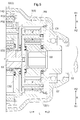
- Axial sectional view of a drive device for a vehicle Skeleton view of the drive unit for vehicles Axial sectional view of the reduction gear Explanation of the configuration of the bevel gear of the reduction gear and thrust force
- FIG. 1 is an axial sectional view of a vehicle drive device 100
- FIG. 2 is a skeleton diagram of the vehicle drive device 100.
- the vehicle drive device 100 includes, for example, a hybrid vehicle using an internal combustion engine and a rotating electric machine as a driving force source of the first wheel 501 and the second wheel 502, and a driving force source of the first wheel 501 and the second wheel 502 as a rotating electric machine. It is a drive unit mounted on an electric vehicle.
- the vehicle drive device 100 includes only the rotary electric machine 2 as a driving force source of the first wheel 501 and the second wheel 502.
- a hybrid vehicle can be realized by driving the other two wheels by the driving force of the internal combustion engine.
- a four-wheel drive electric vehicle can also be realized by applying the vehicle drive device 100 of this embodiment to the other two wheels.
- drive connection refers to a state in which two rotating elements are connected to be able to transmit a driving force, and a state in which the two rotating elements are connected to rotate integrally.
- the two rotary elements include a state in which the driving force is communicably coupled via one or more transmission members.
- Such transmission members include various members that transmit rotation at the same speed or at different speeds, such as a shaft, a gear mechanism, a belt, a chain, and the like.
- the transmission member may include an engagement device that selectively transmits the rotation and the driving force, such as a friction engagement device or a meshing engagement device.
- gear 3 and the differential gear device 4 described below, in the case of “drive connection” for each rotating element, three or more of the rotating elements included in the device do not intervene with each other. It refers to the state of being driven and connected.
- the vehicle drive device 100 includes a case 1, a rotating electrical machine 2 having a rotor shaft 27 for outputting a driving force, a reduction gear 3 including a planetary gear mechanism, and a differential.
- a gear device 4 is provided.
- the reduction gear 3 decelerates the rotation of the rotary electric machine 2 and transmits the driving force to the differential gear device 4.
- the differential gear device 4 distributes the driving force from the rotating electrical machine 2 to each of the first drive shaft 51 and the second drive shaft 52.
- the first drive shaft 51 is drivingly connected to the distribution output shaft 53.
- the differential gear 4 distributes the driving force to the second drive shaft 52 and the distribution output shaft 53, and the first drive shaft 51 receives the distributed driving force via the distribution output shaft 53.
- the rotary electric machine 2, the reduction gear 3, the differential gear unit 4, the first drive shaft 51, the second drive shaft 52, and the distribution output shaft 53 are rotors of the rotary electric machine 2. It is coaxially arranged with reference to the axis 27. Therefore, the direction along the rotor shaft 27 of the rotating electrical machine 2 is equivalent to the direction along the rotating shaft of the vehicle drive device 100, and the direction along the diameter of the rotor shaft 27 of the rotating electrical machine 2 is the vehicle drive This is equivalent to the direction along the diameter of the device 100.
- the direction along the rotor shaft 27 of the rotating electrical machine 2 is referred to as the axial direction L of the vehicle drive device 100, and the direction along the diameter of the rotor shaft 27 of the rotating electrical machine 2 is the diameter of the vehicle drive device 100 It is called direction R.
- the side on which the rotary electric machine 2 is disposed with respect to the reduction gear 3 is referred to as an axial first side L1
- the side on which the differential gear device 4 is disposed relative to the reduction gear 3 is an axial direction It is called the second side L2.
- the outer side opposite to the rotor shaft 27 is referred to as the radially outer side R1
- the inner side on the rotor shaft 27 side is referred to as the radially inner side R2.
- the rotary electric machine 2, the reduction gear 3, and the differential gear device 4 are arranged in the order of the power transmission path.
- the reduction gear 3 has a first planetary gear mechanism 31 and a second planetary gear mechanism 32.
- the rotary electric machine 2, the first planetary gear mechanism 31, the second planetary gear mechanism 32, and the differential gear device 4 are arranged in the described order in the order of the power transmission path.
- the rotating electrical machine 2, the reduction gear 3 (the first planetary gear mechanism 31 and the second planetary gear mechanism 32), and the differential gear device 4 are configured as the rotating electrical machine 2 and the first planetary gear mechanism 31 along the axial direction L.
- the second planetary gear mechanism 32 and the differential gear device 4 are arranged in this order. That is, in any of the order of the power transmission path and the order of the arrangement along the axial direction L, the first planetary gear mechanism 31 is arranged closer to the rotary electric machine 2 than the second planetary gear mechanism 32.
- the case 1 accommodates therein the rotating electrical machine 2, the reduction gear 3, and the differential gear device 4. Further, in the present embodiment, the case 1 further includes a part of the first drive shaft 51 (an end of the second axial side L2) and a part of the second drive shaft 52 (an end of the axial first side L1) And the distribution output shaft 53 are also accommodated inside.
- the case 1 is formed to include a rotary electric machine 2, a reduction gear 3, and a cylindrical peripheral wall portion 10 surrounding the radially outer side R ⁇ b> 1 of the differential gear device 4.
- the case 1 has a case body 11 (first case portion), a body cover 12 (second case portion), and a bottom cover 13.
- the case body 11 is formed in a bottomed cylindrical shape having a bottom portion 11a located at the end of the first axial side L1, and has an opening on the opposite side (axial second side L2) from the bottom 11a There is.
- the main body cover 12 is disposed in contact with the case main body 11 on the first axial side L1 so as to cover the opening, and is formed in a conical cylindrical shape with a smaller diameter toward the second axial side L2 .
- the bottom cover 13 is disposed so as to cover the bottom 11 a on the first side L 1 in the axial direction than the bottom 11 a of the case main body 11.
- the case body 11 and the body cover 12 are fixed to each other by a fixing member (in this embodiment, a bolt).
- the case body 11 and the bottom cover 13 are fixed to each other by a fixing member (in the present embodiment, a bolt).
- the rotary electric machine 2 and part of the reduction gear 3 are disposed in the internal space of the case main body 11.
- the other part of the reduction gear 3 (the second planetary gear mechanism 32), the differential gear device 4, and a part of the second drive shaft 52 (the end of the first axial side L1) It is arranged in space.
- a part of the first drive shaft 51 (an end of the second axial side L 2) is disposed in an internal space formed by the case body 11 and the bottom cover 13.
- the distribution output shaft 53 is disposed in an internal space formed by the case main body 11, the main body cover 12 and the bottom cover 13.
- the case 1 has a support member 14.
- the support member 14 includes a first support member 141 and a second support member 142.
- the first support member 141 is integrally fixed to the case main body 11, and the second support member 142 is integrally fixed to the first support member 141.
- the first support member 141 is fixed to the peripheral wall portion 10 (here, a portion formed by the case main body 11 in the peripheral wall portion 10). That is, in the present embodiment, the support member 14 is supported by the peripheral wall portion 10 of the case 1.
- the first support member 141 is formed to extend along the radial direction R and the circumferential direction between the rotary electric machine 2 and the reduction gear 3 (first planetary gear mechanism 31).
- the end of the radially outer side R1 of the first support member 141 and the case main body 11 are fixed by a fixing member (a bolt in the present embodiment) at at least one place in the circumferential direction of the first support member 141.
- the second support member 142 is formed to extend along the radial direction R and the circumferential direction between the first planetary gear mechanism 31 and the second planetary gear mechanism 32.
- the end portion of the radially outer side R1 of the second support member 142 and the first support member 141 are fixed by a fixing member (in this embodiment, a bolt) at at least one location in the circumferential direction of the second support member 142.
- the second support member 142 is integrally fixed to the first support member 141 on the second side L2 in the axial direction than the first support member 141.
- the rotary electric machine 2 is a permanent magnet including a rotor 21 having a permanent magnet 23 inside a rotor core 22, a stator 24 having a stator coil 26 wound around the stator core 25, and a rotor shaft 27 connected to the rotor core 22. It is a type electric rotating machine.
- the stator 24 (specifically, the stator core 25) is fixed to the case 1, and more specifically, fixed to the peripheral wall portion 10 of the case 1.
- the rotor shaft 27 is connected to the rotor core 22 at a radially inner side R2 of the rotor core 22, and the rotor 21 and the rotor shaft 27 integrally rotate.
- the rotary electric machine 2 is a permanent magnet type rotary electric machine, but may be another type of rotary electric machine such as an induction type rotary electric machine.
- the rotor shaft 27 is formed in a cylindrical shape. A portion of the rotor shaft 27 which protrudes on the first axial side L 1 from the rotor core 22 along the axial direction L is rotatably supported by the case body 11 of the case 1 via the first rotor bearing 61. A portion of the rotor shaft 27 which protrudes on the second axial side L2 from the rotor core 22 along the axial direction L is rotatably supported by the first support member 141 of the support member 14 via the second rotor bearing 62. ing.
- the reduction gear 3 includes the first planetary gear mechanism 31 and the second planetary gear mechanism 32.
- the first planetary gear mechanism 31 includes a first rotating element drivingly connected to the rotating electrical machine 2, a second rotating element, and a third rotating element non-rotatably connected to the fixed member.
- the second planetary gear mechanism 32 has a fourth rotating element that is drivingly connected to the second rotating element of the first planetary gear mechanism 31, a fifth rotating element that is drivingly connected to the differential gear device 4, and a fixed member. And a sixth rotating element connected non-rotatably.
- the support member 14 corresponds to a “fixing member”.
- the fixing member may be constituted by the peripheral wall portion 10 (a part of the peripheral wall portion 10) instead of the configuration in which the fixing member is the support member 14 supported by the peripheral wall portion 10.
- the first planetary gear mechanism 31 includes a first sun gear S31 (first rotating element), a first ring gear R31 (third rotating element), a first carrier C31 (second rotating element), and a plurality of first pinion gears P31. And a single pinion type planetary gear mechanism.
- the first sun gear S31 is an input element of the first planetary gear mechanism 31, and is connected to the rotor shaft 27 of the rotary electric machine 2 so as to rotate integrally therewith.
- the first ring gear R31 is a fixed element of the first planetary gear mechanism 31, and is supported by the first support member 141 so as not to rotate.
- the first carrier C31 is an output element of the first planetary gear mechanism 31, and is connected to a second sun gear S32 (fourth rotating element) of the second planetary gear mechanism 32 as described later.
- the first pinion gear P31 is disposed to mesh with the first sun gear S31 and the first ring gear R31, and is rotatably supported by the first carrier C31.
- the first pinion gear P31 is configured to rotate (rotation) about the axis of the first pinion gear P31 and to rotate (revolution) about the axis of the first sun gear S31.
- a plurality of first pinion gears P31 are provided at intervals from each other along a revolving locus of the first pinion gear P31.
- the second planetary gear mechanism 32 is disposed on the second axial side L2 with respect to the first planetary gear mechanism 31, that is, the side opposite to the first rotating electric machine 2 with respect to the first planetary gear mechanism 31. Is located in The second planetary gear mechanism 32 includes a second sun gear S32 (fourth rotating element), a second ring gear R32 (sixth rotating element), a second carrier C32 (fifth rotating element), and a plurality of second pinion gears P32 And a single pinion type planetary gear mechanism.
- the second sun gear S32 is an input element of the second planetary gear mechanism 32.
- the second sun gear S32 (fourth rotating element) is connected to the first carrier C31 (second rotating element) which is an output element of the first planetary gear mechanism 31.
- the second sun gear S32 is coupled to the first carrier C31 by spline engagement. That is, in the present embodiment, the first planetary gear mechanism 31 and the second planetary gear mechanism 32 are formed independently of each other, and the first planetary gear mechanism 31 and the second planetary gear mechanism 32 are connected by spline engagement.
- the first carrier C31 and the second sun gear S32 may be formed as one component without being limited to the form in which the first carrier C31 and the second sun gear S32 are formed by different members.
- first planetary gear mechanism 31 and the second planetary gear mechanism 32 may be integrally configured to form one reduction gear 3.
- first carrier C31 and the second sun gear S32 are formed by different members, not only the spline engagement but also both may be connected by welding or the like.
- the second drive shaft 52 is disposed adjacent to the differential gear device 4 in the axial direction L, but the first drive shaft 51 and the differential gear in the axial direction L Between the device 4 and the rotary electric machine 2 and the reduction gear 3 are present. For this reason, the first drive shaft 51 is connected to the differential gear device 4 through a distribution output shaft 53 which penetrates the rotary electric machine 2 and the reduction gear 3.
- the first carrier C ⁇ b> 31 and the second sun gear S ⁇ b> 32 which integrally rotate, are rotatably supported with respect to the distribution output shaft 53 via a slide bearing such as a bush.
- the second ring gear R32 (sixth rotating element) is a fixed element of the second planetary gear mechanism 32, and is supported by the second support member 142 so as not to rotate in the circumferential direction.
- the second carrier C32 (fifth rotating element) is an output element of the second planetary gear mechanism 32.
- the second carrier C32 is integrally formed with the differential case D4 of the differential gear device 4.
- the end portion of the first carrier L 32 in the axial direction of the second carrier C 32 is a first differential case between the first planetary gear mechanism 31 and the second planetary gear mechanism 32 of the reduction gear 3. It is rotatably supported by the second support 142 via the bearing 66.
- the second pinion gear P32 is disposed to mesh with the second sun gear S32 and the second ring gear R32, and is rotatably supported by the second carrier C32.
- the second pinion gear P32 is configured to rotate (rotation) around the axis of the second pinion gear P32 and to rotate (revolution) around the axis of the second sun gear S32.
- a plurality of second pinion gears P32 are provided at intervals from each other along the revolution trajectory of the second pinion gear P32.
- the support member 14 (an example of the fixing member) has a first support portion 14 a supporting the first ring gear R 31 and a second support portion 14 b supporting the second ring gear R 32.
- the first support portion 14 a is formed on the first support member 141 of the support member 14
- the second support portion 14 b is formed on the second support member 142 of the support member 14.
- the first ring gear R31 is supported by the first support portion 14a in a state where the first ring gear R31 is at least partially covered by the first support portion 14a from the outer periphery
- the second ring gear R32 is formed on the outer periphery side by the second support portion 14b. And at least partially covered by the second support portion 14b.
- the first support portion 14a supports the first ring gear R31 in a non-rotatable manner in the circumferential direction by being connected from the radially outer side R1 to the first ring gear R31 by spline fitting.
- the first support portion 14a is continuously formed over the entire area in the circumferential direction, and is disposed to cover the first ring gear R31 over the entire area in the circumferential direction.
- the second support portion 14 b supports the second ring gear R ⁇ b> 32 in a non-rotatable manner in the circumferential direction by being connected from the radially outer side R ⁇ b> 1 to the second ring gear R ⁇ b> 32 by spline fitting.
- the second support portion 14b is continuously formed over the entire area in the circumferential direction, and is arranged to cover the second ring gear R32 over the entire area in the circumferential direction.
- the differential gear device 4 distributes the driving force from the rotary electric machine 2 transmitted via the reduction gear 3 to the first wheel 501 and the second wheel 502.
- the differential gear device 4 includes a first drive shaft 51, which is drivingly connected to the distribution output shaft 53, and a second drive shaft, which drive power from the rotating electrical machine 2 is transmitted via the reduction gear 3. It distributes to the 1st wheel 501 and the 2nd wheel 502 via 52 and respectively.
- the differential gear device 4 includes a differential case D4 as an input element, a pinion shaft F4 supported by the differential case D4 so as to rotate integrally with the differential case D4, and a pinion shaft F4.
- first differential pinion gear P41 and a second differential pinion gear P42 which are rotatably supported, and a first side gear B41 and a second side gear B42 as distribution output elements.
- first differential pinion gear P41, the second differential pinion gear P42, the first side gear B41, and the second side gear B42 are all bevel gears.
- the differential gear device 4 is a differential gear device provided with a bevel gear type gear mechanism.
- the differential case D4 is a hollow member, and a pinion shaft F4, a pair of differential pinion gears P4 (a first differential pinion gear P41 and a second differential pinion gear P42), and A first side gear B41 and a second side gear B42 are accommodated.
- the differential case D4 is integrally formed with the second carrier C32 of the second planetary gear mechanism 32, and the second carrier C32 is configured as a part of the differential case D4. Therefore, in the present embodiment, the end of the first carrier L32 in the axial direction on the second carrier C32 functions as the first supported portion D4a of the differential case D4.
- the first supported portion D4a is disposed between the first planetary gear mechanism 31 and the second planetary gear mechanism 32 in the axial direction L.
- the first supported portion D4a is directly supported by a first differential case bearing 66 fixed to the case 1 via the support member 14.
- the first support member 141 is integrally fixed to the case main body 11, and the first support member 141 and the second support member 142 are integrally fixed to each other. Therefore, the first supported portion D4a is supported by the case main body 11 via the first differential case bearing 66.
- the differential case D4 has a second supported portion D4b located on the side (axial second side L2) opposite to the first supported portion D4a in the axial direction L.
- the second supported portion D4b is formed to project along the axial direction L to the second side L2 in the axial direction with respect to the second side gear B42.
- the second supported portion D4b is formed in a cylindrical shape coaxial with the first side gear B41 and the second side gear B42.
- the second supported portion D4b is directly supported by a second differential case bearing 67 fixed to the main body cover 12 of the case 1. That is, the second supported portion D4b is rotatably supported by the main body cover 12 of the case 1 via the second differential case bearing 67.
- the pinion shaft F4 is inserted into a pair of differential pinion gears P4 and rotatably supports them.
- the pinion shaft F4 is inserted into a through hole formed in the differential case D4 along the radial direction R, and is locked by the locking member 43 to the differential case D4.
- the pair of differential pinion gears P4 are attached to the pinion shaft F4 in a state of facing each other at intervals along the radial direction R, and configured to rotate around the pinion shaft F4 in the internal space of the differential case D4. ing.
- the first side gear B41 and the second side gear B42 are rotating elements after distribution in the differential gear device 4.
- the first side gear B41 and the second side gear B42 are provided to be opposed to each other with the pinion shaft F4 interposed therebetween along the axial direction L, and in the internal space of the differential case D4, in the respective circumferential directions It is configured to rotate.
- the first side gear B41 and the second side gear B42 mesh with the first differential pinion gear P41 and the second differential pinion gear P42, respectively.
- a spline for connecting the distribution output shaft 53 is formed on the inner peripheral surface of the first side gear B41.
- a spline for connecting the second drive shaft 52 is formed on the inner peripheral surface of the second side gear B42.
- the distribution output shaft 53 is a member for transmitting the driving force from the rotary electric machine 2 distributed by the differential gear device 4 to the first drive shaft 51.
- the distribution output shaft 53 passes through the radially inner side R2 of the rotor shaft 27 of the rotary electric machine 2 in the axial direction L.
- a spline for connecting to the first side gear B41 of the differential gear device 4 is formed on the outer peripheral surface of the end portion of the distribution output shaft 53 on the second axial side L2.
- the distribution output shaft 53 and the first side gear B41 are connected so as to rotate integrally as a result of the splines engaging with the splines of the inner peripheral surface of the first side gear B41.
- a connecting portion 53 a for connecting the first drive shaft 51 is formed at the end of the first axial side L 1 of the distribution output shaft 53.
- the connecting portion 53 a extends from the portion on the first axial side L 1 to the internal space of the bottom cover 13 than the rotary electric machine 2 in the internal space of the case main body 11.
- the connecting portion 53 a is formed in a cylindrical shape coaxial with a portion of the distribution output shaft 53 other than the connecting portion 53 a.
- the connecting portion 53 a has an outer diameter larger than the outer diameter of the portion of the distribution output shaft 53 other than the connecting portion 53 a.
- the connecting portion 53a is rotatably supported by the bottom cover 13 of the case 1 via the first output bearing 68, and rotatably supported by the bottom portion 11a of the case body 11 via the second output bearing 69.
- a spline for connecting the first drive shaft 51 is formed on the inner peripheral surface of a portion of the connecting portion 53a on the second axial side L2.
- the first drive shaft 51 is drivingly connected to the first wheel 501
- the second drive shaft 52 is drivingly connected to the second wheel 502.
- the connecting portion 53a is provided at the end of the first axial side L1 of the distribution output shaft 53
- the first drive shaft 51 and the connecting portion 53a of the distribution output shaft 53 are connected by splines.
- a flange yoke is provided at the end of the first axial direction L1 of the distribution output shaft 53 instead of the connecting portion 53a, and the flange yoke and the first drive are provided.
- the shaft 51 may be fastened by a bolt.
- the first sun gear S31 which is an input element
- the rotary electric machine 2 specifically, the rotor shaft 27 of the rotary electric machine 2.
- the driving force is output from the first carrier C31 which is an output element while decelerating at the first reduction ratio.
- the second sun gear S32 which is an input element
- the driving force is output from the second carrier C32 which is an element.
- the first reduction ratio which is the reduction ratio of the first planetary gear mechanism 31
- the second reduction ratio which is the reduction ratio of the second planetary gear mechanism 32.
- the first reduction ratio is smaller than the second reduction ratio
- the rotational speed input to the second planetary gear mechanism 32 is higher than when the first reduction ratio and the second reduction ratio are equal.
- the input torque to the 2 planetary gear mechanism 32 is reduced.
- the second planetary gear mechanism 32 has a smaller input torque, the required mechanical strength is reduced, and downsizing is possible.
- the tooth width of the gear mechanism is often increased in the axial direction L. In this case, for example, to increase the widths of the gears of the first planetary gear mechanism 31 and the second planetary gear mechanism 32 along the axial direction L (first gear width W1, second gear width W2: see FIG. 3). Become.
- the second gear width W2 which is the gear width of the second planetary gear mechanism 32. Since the first planetary gear mechanism 31 has higher rotation and lower torque than the second planetary gear mechanism 32, the first gear width W1, which is the gear width of the first planetary gear mechanism 31, is obtained even if the transmission torque becomes somewhat large. Will not be so big. That is, the reduction amount of the second gear width W2 is larger than the increment of the first gear width W1 according to the relationship between the first reduction ratio and the second reduction ratio, so that the axial direction L as a whole of the reduction gear 3 Can be reduced. Thus, the length of axial direction L of reduction gear 3 can be shortened by setting up gear ratio of two planetary gear mechanisms (31, 32) with which reduction gear 3 is provided appropriately.
- the first gear width W1 is smaller than the second gear width W2 as shown in FIG.
- the second planetary gear mechanism 32 is disposed on the output side of the reduction gear 3 with respect to the first planetary gear mechanism 31 in the order of the power transmission path, and the rotating electrical machine 2 after being decelerated by the first planetary gear mechanism 31. Driving force is transmitted to the second planetary gear mechanism 32. Therefore, the transmission torque is larger in the second planetary gear mechanism 32 than in the first planetary gear mechanism 31.
- the transmission torque can be reduced by reducing the first gear width W1 of the first planetary gear mechanism 31 having a relatively small transmission torque as compared to the second gear width W2 of the second planetary gear mechanism 32 having a relatively large transmission torque.
- the speed reducer 3 can be configured to have an appropriate structure according to the size of the vehicle.
- the second gear width W2 be smaller than a length obtained by multiplying the first gear width W1 by the first reduction ratio.
- the second gear width W2 has a length obtained by multiplying the first gear width W1 by the first reduction ratio.
- the transmission torque of the second planetary gear mechanism 32 is larger than that of the first planetary gear mechanism 31, the rotational speed is lower than that of the first planetary gear mechanism 31. That is, because the rotational speed is low, the required durability can be ensured even if the second gear width W2 is smaller than the length obtained by multiplying the first gear width W1 by the first reduction ratio.
- the length of the second planetary gear mechanism 32 in the axial direction L can be shortened, whereby the reduction gear 3
- the length of the entire axial direction L of can also be shortened.
- the second sun gear diameter ⁇ 2 which is the diameter of the second sun gear S32 be smaller than the first sun gear diameter ⁇ 1 which is the diameter of the first sun gear S31.
- the first planetary gear mechanism 31 and the second planetary gear mechanism 32 have the ring gear as the fixed element, the sun gear as the input element, and the carrier as the output element.
- the ring gear has the same diameter, the reduction ratio increases as the diameter of the sun gear decreases. That is, even if the configurations of the gears such as the diameter and the number of teeth are slightly different, it is easy to increase the reduction ratio as the diameter of the sun gear is smaller.
- the second sun gear diameter ⁇ 2 is smaller than the first sun gear diameter ⁇ 1. Therefore, the reduction gear 3 in which the first reduction gear ratio is smaller than the second reduction gear ratio is appropriately realized.
- the first planetary gear mechanism 31 and the second planetary gear mechanism 32 are higher in strength than the spur gear and smaller in gear noise, they use a bevel gear suitable for use in high rotation. It is configured.
- the helical gear generates a thrust force which is a force in the direction along the rotation axis due to its structure.
- a thrust bearing is generally provided in the gear device using a bevel gear. As shown in FIGS.
- a first thrust bearing 71 is provided on the first axial side L1 with respect to the first planetary gear mechanism 31, and the first planetary gear mechanism 31 and the second planetary gear mechanism 32
- a second thrust bearing 72 is provided between the axial directions L
- a third thrust bearing 73 is provided on the second axial side L2 with respect to the second planetary gear mechanism 32. More specifically, the first thrust bearing 71 is provided on the first side L1 in the axial direction with respect to the first sun gear S31. In the present embodiment, as shown in FIG.
- the above-described support member 14 is on the opposite side of the first planetary gear mechanism 31 to the side on which the second planetary gear mechanism 32 is disposed in the axial direction L (that is, It is supported by the peripheral wall portion 10 of the case 1 so as to have a portion (target portion 14c) disposed on the first planetary gear mechanism 31 in the axial direction first side L1).
- the target portion 14 c of the case 1 is formed on the first support member 141 of the support member 14.
- a first thrust bearing 71 is disposed between the first sun gear S31 and the support member 14 (specifically, the target portion 14c) in the axial direction L.
- the target portion 14 c may be integrally formed with the peripheral wall portion 10, such as the supporting member 14 may be integrally formed with the peripheral wall portion 10.
- the second thrust bearing 72 is provided on the second side L2 in the axial direction with respect to the first sun gear S31, and on the first side L1 in the axial direction with respect to the connecting portion of the first carrier C31 and the second sun gear S32.
- the third thrust bearing 73 is provided on the second side L2 in the axial direction with respect to the second sun gear S32.
- FIG. 4 shows the configuration and thrust force of the bevel gear of the reduction gear 3.
- the first planetary gear mechanism 31 and the second planetary gear mechanism 32 have a first thrust force SF1 which is a thrust force of the first planetary gear mechanism 31 and a second thrust force SF2 which is a thrust force of the second planetary gear mechanism 32.
- the twist angles of the oblique teeth are formed to be opposite to each other in the axial direction L. If the thrust forces (SF1, SF2) generated by the first planetary gear mechanism 31 and the second planetary gear mechanism 32, both of which are configured using oblique gears, are in opposite directions to each other, the respective thrust forces (SF1) , SF2) can be canceled out.
- the twist angles of the oblique teeth are set such that the first thrust force SF1 generated in the first sun gear S31 and the second thrust force SF2 generated in the second sun gear S32 face in the direction opposite to each other. It is done. Thereby, the load applied to the first thrust bearing 71 and the third thrust bearing 73 arranged on the outer side in the axial direction L with respect to the first sun gear S31 and the second sun gear S32 can be reduced.
- the reduction gear 3 becomes longer in the axial direction L, which hinders downsizing.
- the first thrust bearing 71 and the third thrust bearing 73 can be The load can be reduced. As a result, even if the first thrust bearing 71 and the third thrust bearing 73 are small, the durability of the reduction gear 3 can be secured.
- the thrust force vectorizes the force generated in the direction orthogonal to the oblique teeth in the direction parallel to the rotation axis (here, coincident with the axial direction L) and the direction orthogonal to the rotation axis Corresponds to the component parallel to the rotation axis. That is, the thrust force increases as the force generated in the direction orthogonal to the oblique teeth increases. Therefore, the magnitude of the thrust force has a correlation with the transfer torque, and the larger the transfer torque, the larger the thrust force.
- the second thrust force SF2 tends to be larger than the first thrust force SF1.
- the magnitude of the thrust force also has a correlation with the twist angle of the bevel teeth in the bevel gear, and the larger the twist angle, the larger the thrust force.
- the twist angle is the angle between the rotation axis of the bevel gear and the teeth of the bevel gear.
- the first twist angle ⁇ 1 which is the twist angle of the oblique teeth of the first planetary gear mechanism 31 is larger than the second twist angle ⁇ 2 which is the twist angle of the oblique teeth of the second planetary gear mechanism 32.
- the ratio of the thrust force in the force output from the gear mechanism is larger in the first planetary gear mechanism 31 than in the second planetary gear mechanism 32.
- the thrust force of the second planetary gear mechanism 32 tends to be larger.
- the first twist angle ⁇ 1 is larger than the second twist angle ⁇ 2 it is possible to reduce the difference in magnitude of the thrust force caused by the difference in the transmission torque.
- the first thrust force SF1 generated in the first sun gear S31 and the second thrust force SF2 generated in the second sun gear S32 act in a direction opposite to each other to at least a part of each other's force. Exemplifies the form of canceling each other.
- the twist angles of the oblique teeth be set such that the first thrust force SF1 generated in the first ring gear R31 and the second thrust force SF2 generated in the second ring gear R32 act in the direction opposite to each other. is there.
- the entire thrust force of the reduction gear 3 can be reduced by canceling at least a part of each other's forces.
- the first thrust force SF1 generated in the first sun gear S31 and the second thrust force SF2 generated in the second sun gear S32 act in the direction of being separated from each other.
- the bevel gear type differential gear device 4 is illustrated.
- the differential gear device 4 is not limited to the bevel gear type, and may be a planetary gear type as in the third planetary gear mechanism 9 shown in FIG. 5.
- the third planetary gear mechanism 9 is a double pinion type planetary gear mechanism, and has a third sun gear S9, a third carrier C9, and a third ring gear R9.
- the third ring gear R9 is an input element of the third planetary gear mechanism 9, and is connected to rotate integrally with the second carrier C32 of the second planetary gear mechanism 32.
- the third sun gear S9 and the third carrier C9 are the distribution output elements of the third planetary gear mechanism 9.
- the third carrier C9 is connected to the distribution output shaft 53
- the third sun gear S9 is connected to the second drive shaft 52 by spline engagement.
- the differential case D4 of the differential gear device 4 is integrally formed with the second carrier C32 of the second planetary gear mechanism 32 has been described as an example.
- the differential case D4 and the second carrier C32 may be configured to be separable from each other (for example, a configuration in which the differential case D4 and the second carrier C32 are mutually connected by bolts, splines, etc.).
- the second gear width W2 has been described as an example of a configuration smaller than the length of the first gear width W1 multiplied by the first reduction ratio.
- the second gear width W2 may be equal to or larger than the length obtained by multiplying the first gear width W1 by the first reduction ratio.
- the configuration in which the second sun gear diameter ⁇ 2 is smaller than the first sun gear diameter ⁇ 1 has been described as an example.
- the second sun gear diameter ⁇ 2 may be larger than the first sun gear diameter ⁇ 1.
- the diameter of the second ring gear R32 is larger than the diameter of the first ring gear R31. It is good to enlarge it.
- the thrust force of the first planetary gear mechanism 31 (first thrust force SF1) and the thrust force of the second planetary gear mechanism 32 (second thrust force SF2) are opposite to each other in the axial direction L
- first thrust force SF1 and second thrust force SF2 are opposite to each other in the axial direction L
- second thrust force SF2 the thrust force of the first planetary gear mechanism 31
- the twist angles of the oblique teeth may be formed such that the first thrust force SF1 and the second thrust force SF2 are in the same direction in the axial direction L. .
- the twist angle (first twist angle ⁇ 1) of the oblique teeth of the first planetary gear mechanism 31 is larger than the twist angle (second twist angle ⁇ 2) of the oblique teeth of the second planetary gear mechanism 32
- the configuration has been described as an example. However, without being limited to such a configuration, the first twist angle ⁇ 1 and the second twist angle ⁇ 2 may be the same. Further, the first twist angle ⁇ 1 may be smaller than the second twist angle ⁇ 2.
- the vehicle drive device (100) includes, as one aspect, A rotating electric machine (2) serving as a driving force source for the first wheel (501) and the second wheel (502); A reduction gear (3) for decelerating the rotation of the rotating electric machine (2); A differential gear (4) for distributing the driving force from the rotating electrical machine (2) transmitted through the reduction gear (3) to the first wheel (501) and the second wheel (502) , And The reduction gear (3) and the differential gear (4) are arranged coaxially with the rotating electrical machine (2);
- the reduction gear (3) has a first planetary gear mechanism (31) and a second planetary gear mechanism (32), and the first planetary gear mechanism (31) is a second planetary gear in the order of power transmission path.
- a first reduction ratio which is a reduction ratio of the first planetary gear mechanism (31)
- a second reduction ratio which is a reduction ratio of the second planetary gear mechanism (32).
- the three devices (3, 4, 5) are parallel to one another.
- the dimension in the radial direction (R) of the vehicle drive device (100) can be reduced as compared to the case where the shafts are separately arranged.
- the length of the entire axial direction (L) of the reduction gear (3) can be shortened as described below, so that the vehicle drive device (100)
- These three devices (3, 4, 5) can be coaxially arranged while suppressing the increase in size to L).
- first reduction ratio is smaller than the second reduction ratio as compared to the case where the first reduction ratio of the first planetary gear mechanism (31) and the second reduction ratio of the second planetary gear mechanism (32) are equal
- the rotational speed input to the second planetary gear mechanism (32) increases, and the input torque to the second planetary gear mechanism (32) decreases.
- the second planetary gear mechanism (32) has a smaller input torque, the required mechanical strength is reduced, and downsizing is possible.
- the tooth width of the gear mechanism is often elongated in the axial direction (L).
- the length in the axial direction (L) of the second planetary gear mechanism (32) can be shortened, whereby the reduction gear (3)
- the overall axial length (L) of can also be shortened.
- the length of the axial direction (L) of the vehicle drive device (100) can be shortened.
- the overall downsizing of the vehicle drive device (100) in both the radial direction (R) and the axial direction (L) can be achieved.
- the first planetary gear mechanism (31) corresponds to the first rotating element (S31), the second rotating element (C31), and the fixing member (14) which are drivingly connected to the rotating electric machine (2). And a third rotating element (R31) non-rotatably connected, and the second planetary gear mechanism (32) is drivingly connected to the second rotating element (C31) of the first planetary gear mechanism (31).
- the first planetary gear mechanism (31) is disposed closer to the rotating electrical machine (2) than the second planetary gear mechanism (32) in the order of the power transmission path, and the second planetary gear mechanism (32) Can appropriately configure the reduction gear (3) disposed closer to the rotating electrical machine (2) than the first planetary gear mechanism (31).
- the first planetary gear mechanism (31) includes the first rotation element (S31), the second rotation element (C31), and the third rotation element (R31), and the second planet gear mechanism
- the gear mechanism (32) includes the fourth rotating element (S32), the fifth rotating element (C32), and the sixth rotating element (R32)
- the first planetary gear mechanism (31) is configured to
- the first sun gear (S31) which is the first rotating element (S31), the first carrier (C31) which is the second rotating element (C31), and the first ring gear (the third rotating element (R31) R31
- the second planetary gear mechanism (32) includes a second sun gear (S32) which is the fourth rotating element (S32) and a second carrier which is the fifth rotating element (C32).
- the fixing member (14) has a first support portion (14a) and a second support portion (14b), and the first ring gear (R31) Is supported by the first support portion (14a) in a state of being at least partially covered by the first support portion (14a) from the outer peripheral side, and the second ring gear (R32) is the second support It is preferable that the second support portion (14b) supports the second support portion (14b) in a state of being at least partially covered by the portion (14b) from the outer peripheral side.
- the first ring gear (R31) and the second ring gear (R32) are supported by supporting the first ring gear (R31) and the second ring gear (R32) from the outer peripheral side by the support portions (14a, 14b). It can be connected non-rotatably to the fixing member (14).
- the reduction gear (3) and the differential gear device (4) are arranged coaxially with the rotating electrical machine (2) as in the vehicle drive device (100) according to the present disclosure, the vehicle drive device In order to keep the dimension in the radial direction (R) of (100) small, the space allowance is small on the radially outer side (R1) with respect to the first planetary gear mechanism (31) and the second planetary gear mechanism (32) Prone.
- the support portions (14a, 14b) are arranged to cover the ring gears (R31, R32) at least partially from the outer peripheral side, so the ring gears (R31, R32)
- the dimension of the radial direction (R) of the support portion (14a, 14b) necessary for supporting can be kept small. Therefore, the first ring gear (R31) and the second ring gear can be provided even when there is little space in the radial direction outer side (R1) with respect to the first planetary gear mechanism (31) and the second planetary gear mechanism (32). (R 32) can be properly supported by the support portions (14a, 14b).
- a case (1) to which the stator (24) of the rotary electric machine (2) is fixed is further provided, and the fixing member (14) is constituted by the peripheral wall portion (10) of the case (1)
- the support member (14) is supported by the peripheral wall portion (10).
- the first ring gear (R31) and the second ring gear (R32) can be non-rotatably coupled to the case (1) to which the stator (24) of the rotating electrical machine (2) is fixed.
- the first ring gear (R31) may have a small space allowance on the radially outer side (R1) with respect to the first planetary gear mechanism (31) and the second planetary gear mechanism (32).
- the second ring gear (R32) can be properly supported by the support portions (14a, 14b), so the peripheral wall portion (10) can be attached to the first planetary gear mechanism (31) and the second planetary gear mechanism (32). It is possible to reduce the size of the vehicle drive device (100) in the radial direction (R) by arranging it close to the other.
- the reduction gear (3) is disposed between the rotating electrical machine (2) and the differential gear (4) in the axial direction (L).
- a simple vehicle drive device (100) can be configured, and downsizing of the vehicle drive device (100) is realized.
- the first gear width (W1) which is the width of the gear along the axial direction (L) of the first planetary gear mechanism (31), corresponds to the axial direction (L of the second planetary gear mechanism (32) It is preferable that the width is smaller than the second gear width (W2) which is the width of the gear along.
- the second planetary gear mechanism (32) is disposed on the output side of the reduction gear (3) with respect to the first planetary gear mechanism (31) in the order of the power transmission path, and the first planetary gear mechanism (31)
- the driving force of the rotating electrical machine (2) after being decelerated is transmitted to the second planetary gear mechanism (32). Therefore, the transmission torque is larger in the second planetary gear mechanism (32) than in the first planetary gear mechanism (31). From the viewpoint of mechanical strength and the like, it is preferable to increase the width of the gear along the axial direction (L) as the transmission torque is larger.
- the first gear width (W1) of the first planetary gear mechanism (31) having a relatively small transmission torque as compared to the second gear width (W2) of the second planetary gear mechanism (32) having a relatively large transmission torque can be configured, the speed reduction gear (3) having a structure according to the magnitude of the transmission torque can be configured. Thereby, the length in the axial direction (L) of the reduction gear (3) can be shortened.
- the first gear width (W1) which is the width of the gear along the axial direction (L) of the first planetary gear mechanism (31), corresponds to that of the second planetary gear mechanism (32).
- the width of the gear along the axial direction (L) is smaller than the second gear width (W2)
- the second gear width (W2) is reduced to the first gear width (W1). It is preferable that the length is smaller than the length multiplied by the ratio.
- the second gear width (W2) is equal to the first gear width (W1). It is the length multiplied by the reduction ratio.
- the second planetary gear mechanism (32) has a larger transfer torque than the first planetary gear mechanism (31), the rotational speed is lower than that of the first planetary gear mechanism (31). Therefore, the required durability can be secured even if the second gear width (W2) is smaller than the length obtained by multiplying the first gear width (W1) by the first reduction ratio.
- the second gear width (W2) is smaller than the length of the first gear width (W1) multiplied by the first reduction ratio, the length in the axial direction (L) of the second planetary gear mechanism (32) is shortened. It is also possible to reduce the overall axial length (L) of the reduction gear (3).
- the first planetary gear mechanism (31) has a first sun gear (S31), a first carrier (C31), and a first ring gear (R31)
- the second planetary gear mechanism (32) has a first 2 has a sun gear (S32), a second carrier (C32) and a second ring gear (R32), and the diameter ( ⁇ 2) of the second sun gear (S32) is the diameter ( ⁇ 1) of the first sun gear (S31) It is suitable that it is smaller.
- the reduction gear can be easily increased as the diameter of the sun gear is smaller. If the diameter ( ⁇ 2) of the second sun gear (S32) is smaller than the diameter ( ⁇ 1) of the first sun gear (S31), the reduction of speed of the second planetary gear mechanism (32) compared to the first planetary gear mechanism (31) It is easy to increase the ratio. Therefore, according to this configuration, it is possible to easily realize the reduction gear (3) in which the first reduction gear ratio is smaller than the second reduction gear ratio.
- the first planetary gear mechanism (31) is drivingly connected to the rotating electrical machine (2), the first rotating element (S31), the second rotating element (C31), and the fixing member (14).
- the second planetary gear mechanism (32) is drivingly connected to the second rotary element (C31) of the first planetary gear mechanism (31).
- the first rotating element (S31) corresponds to the first sun gear (S31)
- the second rotating element (C31) corresponds to the first carrier (C31)
- the third rotating element (R31) is the first ring gear Corresponding to (R31)
- the fourth rotating element (S32) is the second sun gear Corresponding to S32
- the fifth rotating element (C32) corresponds to the second carrier (C32)
- the sixth rotary element (R32) is preferred to correspond to the second ring gear (R32).
- the first planetary gear mechanism (31) When the first planetary gear mechanism (31) is disposed closer to the rotating electrical machine (2) than the second planetary gear mechanism (32) along the axial direction (L), the first planetary gear mechanism In the gear mechanism (31) and the second planetary gear mechanism (32), a thrust force (SF1) of the first planetary gear mechanism (31) and a thrust force (SF2) of the second planetary gear mechanism (32) Are formed in mutually opposite directions in the axial direction (L), and the twist angle (.theta.1) of the oblique teeth of the first planetary gear mechanism (31) is the second planetary gear It is preferable that the twist angle ( ⁇ 2) of the oblique teeth of the mechanism (32) be larger.
- the helical gear generates a thrust force parallel to the rotation axis due to its structure. If the thrust forces (SF1, SF2) generated by the first planetary gear mechanism (31) and the second planetary gear mechanism (32), both of which are configured using oblique gears, are opposite to each other, It is possible to make thrust forces (SF1, SF2) cancel each other.
- a thrust bearing is disposed adjacent to the axial direction (L) on the helical gear. When the generated thrust force is large, the load on the thrust bearing is increased, which affects the durability of the reduction gear (3) and the vehicle drive device (100).
- the magnitude of the thrust force has a correlation with the transfer torque, and the larger the transfer torque, the larger the thrust force. Since the transmission torque of the second planetary gear mechanism (32) is larger than the transmission torque of the first planetary gear mechanism (31), the thrust force (SF2) of the second planetary gear mechanism (32) is the first planetary gear mechanism It becomes larger than the thrust force (SF1) of (31). Further, the magnitude of the thrust force also has a correlation with the twist angle of the bevel teeth in the bevel gear, and the larger the twist angle, the larger the thrust force.
- the force output from the gear mechanism is The proportion of the thrust force is greater in the first planetary gear mechanism (31) than in the second planetary gear mechanism (32). That is, according to this configuration, it is possible to reduce the difference in magnitude of the thrust force caused by the difference in transmission torque by the twist angle of the oblique teeth. That is, the loads on the thrust bearings (71, 73) can be reduced by appropriately canceling the thrust forces of the two planetary gear mechanisms (31, 32). As a result, it is possible to realize a reduction gear (3) and a drive device for a vehicle (100) having a short length in the axial direction (L) and excellent in durability.
Abstract
A speed reduction device (3) that reduces the speed of rotation of a rotary electric machine (2) and a differential gear device (4) that distributes a drive force from the rotary electric machine (2) between a first wheel and a second wheel are arranged coaxially with the rotary electric machine (2). The speed reduction device (3) includes a first planet gear mechanism (31) and a second planet gear mechanism (32). In the order of a power-transmitting path, the first planet gear mechanism (31) is arranged more toward the rotary electric machine (2) than the second planet gear mechanism (32). The reduction ratio of the first planet gear mechanism (31) is smaller than the reduction ratio of the second planet gear mechanism (32).
Description
本発明は、第1車輪及び第2車輪の駆動力源となる回転電機と、回転電機の回転を減速する減速装置と、減速装置を介して伝達される回転電機からの駆動力を第1車輪と第2車輪とに分配する差動歯車装置とを備えた車両用駆動装置に関する。
According to the present invention, a driving force from a rotating electric machine transmitted through the speed reducing device as the first electric machine is a rotating electric machine serving as a driving force source of the first wheel and the second wheel, a reduction gear for reducing the rotation of the rotating electric machine And a second differential gear unit for distributing the second and third wheels.
車両用駆動装置の一例が、特開平10-287142号公報(特許文献1)に開示されている。以下、背景技術の説明において括弧内に示す符号は特許文献1のものである。特許文献1の車両用駆動装置は、モータ(M)と、ディファレンシャル装置(Gd)と、モータ(M)の動力をディファレンシャル装置(Gd)に伝達するカウンタギヤ機構(Gc)とを備えている。カウンタギヤ機構(Gc)は、モータ(M)の回転を減速してディファレンシャル装置(Gd)に伝達する減速装置を構成している。そして、特許文献1の図1及び図2に示されているように、モータ(M)、ディファレンシャル装置(Gd)、及びカウンタギヤ機構(Gc)は、互いに平行な3つの軸に分かれて配置されている。
An example of a vehicle drive device is disclosed in Japanese Patent Laid-Open No. 10-287142 (Patent Document 1). Hereinafter, reference numerals in parentheses in the description of the background art are those of Patent Document 1. The vehicle drive device of Patent Document 1 includes a motor (M), a differential device (Gd), and a counter gear mechanism (Gc) for transmitting the power of the motor (M) to the differential device (Gd). The counter gear mechanism (Gc) constitutes a reduction gear that decelerates the rotation of the motor (M) and transmits it to the differential device (Gd). Then, as shown in FIGS. 1 and 2 of Patent Document 1, the motor (M), the differential device (Gd), and the counter gear mechanism (Gc) are arranged separately in three mutually parallel axes. ing.
ところで、車両用駆動装置の車載性を考慮すると、装置全体は極力小型化されていることが好ましい。この点に関して、特許文献1の車両用駆動装置では、回転電機、減速装置(特許文献1ではカウンタギヤ機構)、及び差動歯車装置の3つの装置が、互いに平行な3つの軸に分かれて配置されるため、装置全体が径方向に大型化しやすい。装置全体を径方向に小型化するために、これら3つの装置を同軸上に配置することが考えられるが、この場合には、装置全体が軸方向に大型化しやすくなる。
By the way, in consideration of the in-vehicle performance of the vehicle drive device, it is preferable that the entire device be miniaturized as much as possible. In this regard, in the vehicle drive device of Patent Document 1, the three devices of the rotary electric machine, the reduction gear (the counter gear mechanism in Patent Document 1), and the differential gear device are arranged separately in three mutually parallel axes. Therefore, the entire apparatus is likely to be enlarged in the radial direction. In order to miniaturize the entire device in the radial direction, it is conceivable to arrange these three devices coaxially, but in this case, the entire device tends to be enlarged in the axial direction.
そこで、径方向及び軸方向の双方における装置全体の小型化を図ることが可能な車両用駆動装置の実現が望まれる。
Therefore, it is desired to realize a vehicle drive device capable of downsizing the entire device in both the radial direction and the axial direction.
1つの態様として、上記に鑑みた車両用駆動装置は、
第1車輪及び第2車輪の駆動力源となる回転電機と、
前記回転電機の回転を減速する減速装置と、
前記減速装置を介して伝達される前記回転電機からの駆動力を前記第1車輪と前記第2車輪とに分配する差動歯車装置と、を備え、
前記減速装置及び前記差動歯車装置が前記回転電機と同軸に配置され、
前記減速装置は、第1遊星歯車機構と第2遊星歯車機構とを有し、動力伝達経路の順で前記第1遊星歯車機構が前記第2遊星歯車機構よりも前記回転電機の側に配置され、
前記第1遊星歯車機構の減速比である第1減速比が、前記第2遊星歯車機構の減速比である第2減速比よりも小さい。 As one aspect, the vehicle drive device in view of the above is:
A rotating electrical machine serving as a driving force source of the first wheel and the second wheel;
A reduction gear that decelerates the rotation of the rotating electrical machine;
And a differential gear device for distributing the driving force from the rotating electrical machine transmitted through the reduction gear to the first wheel and the second wheel.
The reduction gear and the differential gear device are disposed coaxially with the rotating electrical machine;
The reduction gear transmission includes a first planetary gear mechanism and a second planetary gear mechanism, and the first planetary gear mechanism is disposed closer to the rotary electric machine than the second planetary gear mechanism in the order of the power transmission path. ,
A first reduction ratio, which is a reduction ratio of the first planetary gear mechanism, is smaller than a second reduction ratio, which is a reduction ratio of the second planetary gear mechanism.
この構成によれば、減速装置及び差動歯車装置が回転電機と同軸に配置されるため、これら3つの装置が互いに平行な3つの軸に分かれて配置される場合に比べて、車両用駆動装置の径方向の寸法を小さく抑えることができる。その上で、この構成によれば、以下に述べるように減速装置の全体の軸方向の長さを短縮することができるため、車両用駆動装置が軸方向に大型化することを抑制しつつ、これら3つの装置を同軸上に配置することができる。
According to this configuration, since the reduction gear and the differential gear device are disposed coaxially with the rotating electrical machine, the drive device for a vehicle is compared to the case where these three devices are disposed separately in three parallel axes. The radial dimension of can be kept small. Moreover, according to this configuration, since the overall axial length of the reduction gear can be shortened as described below, it is possible to suppress an increase in the size of the vehicle drive device in the axial direction. These three devices can be arranged coaxially.
第1遊星歯車機構の第1減速比と、第2遊星歯車機構の第2減速比とが同等の場合に比べて、第1減速比が第2減速比よりも小さいと、第2遊星歯車機構に入力される回転速度が高くなると共に、第2遊星歯車機構の入力トルクが小さくなる。第2遊星歯車機構は、入力トルクが小さくなることにより、必要な機械的強度が低減されて小型化が可能となる。大きな入力トルクに対応して機械的な強度を向上させる場合には歯車機構の歯幅を軸方向に長くすることが多い。従って、第2遊星歯車機構への入力トルクを低減させることで第2遊星歯車機構の軸方向の長さを短縮することができ、それによって減速装置の全体の軸方向の長さも短縮することができる。この結果、車両用駆動装置の軸方向の長さの短縮を図ることができる。
このように、本構成によれば、径方向及び軸方向の双方における車両用駆動装置の全体の小型化を図ることができる。 The second planetary gear mechanism if the first reduction ratio is smaller than the second reduction ratio as compared to the case where the first reduction ratio of the first planetary gear mechanism is equal to the second reduction ratio of the second planetary gear mechanism As the rotational speed input to the second planetary gear mechanism increases, the input torque of the second planetary gear mechanism decreases. As the second planetary gear mechanism has a smaller input torque, the required mechanical strength is reduced, which allows downsizing. In order to improve mechanical strength in response to a large input torque, the tooth width of the gear mechanism is often elongated in the axial direction. Therefore, by reducing the input torque to the second planetary gear mechanism, the axial length of the second planetary gear mechanism can be shortened, whereby the overall axial length of the reduction gear can also be shortened. it can. As a result, the axial length of the vehicle drive device can be shortened.
As described above, according to this configuration, it is possible to miniaturize the entire vehicle drive device in both the radial direction and the axial direction.
さらなる特徴と利点は、図面を参照して説明する車両用駆動装置の実施形態についての以下の記載から明確となる。
Further features and advantages will become apparent from the following description of the embodiment of the vehicle drive described with reference to the drawings.
以下、車両用駆動装置の実施形態を図面に基づいて説明する。図1は、車両用駆動装置100の軸方向断面図であり、図2は、車両用駆動装置100のスケルトン図である。車両用駆動装置100は、例えば、内燃機関及び回転電機を第1車輪501及び第2車輪502の駆動力源とするハイブリッド自動車や、回転電機を第1車輪501及び第2車輪502の駆動力源とする電気自動車に搭載される駆動装置である。図1及び図2に示すように、車両用駆動装置100は、第1車輪501及び第2車輪502の駆動力源として回転電機2のみを備えている。2輪駆動の4輪車の場合には、これによって電気自動車が実現できる。また、4輪駆動の4輪車の場合には、他の2輪を内燃機関の駆動力によって駆動することでハイブリッド車両が実現できる。当然ながら、4輪駆動の4輪車の場合には、本実施形態の車両用駆動装置100を他の2輪にも適用することで、4輪駆動の電気自動車を実現することもできる。
Hereinafter, an embodiment of a vehicle drive device will be described based on the drawings. FIG. 1 is an axial sectional view of a vehicle drive device 100, and FIG. 2 is a skeleton diagram of the vehicle drive device 100. As shown in FIG. The vehicle drive device 100 includes, for example, a hybrid vehicle using an internal combustion engine and a rotating electric machine as a driving force source of the first wheel 501 and the second wheel 502, and a driving force source of the first wheel 501 and the second wheel 502 as a rotating electric machine. It is a drive unit mounted on an electric vehicle. As shown in FIGS. 1 and 2, the vehicle drive device 100 includes only the rotary electric machine 2 as a driving force source of the first wheel 501 and the second wheel 502. In the case of a two-wheel drive four-wheeled vehicle, this enables an electric vehicle to be realized. Further, in the case of a four-wheel drive four-wheeled vehicle, a hybrid vehicle can be realized by driving the other two wheels by the driving force of the internal combustion engine. As a matter of course, in the case of a four-wheel drive four-wheeled vehicle, a four-wheel drive electric vehicle can also be realized by applying the vehicle drive device 100 of this embodiment to the other two wheels.
尚、以下の説明において、「駆動連結」とは、2つの回転要素が駆動力を伝達可能に連結された状態を指し、当該2つの回転要素が一体的に回転するように連結された状態、或いは当該2つの回転要素が1つ又は2つ以上の伝動部材を介して駆動力を伝達可能に連結された状態を含む。このような伝動部材としては、回転を同速で又は変速して伝達する各種の部材、例えば、軸、歯車機構、ベルト、チェーン等が含まれる。尚、伝動部材として、回転及び駆動力を選択的に伝達する係合装置、例えば、摩擦係合装置、噛み合い式係合装置等が含まれていても良い。但し、下記において説明する減速装置3及び差動歯車装置4において、各回転要素について「駆動連結」という場合には、当該装置が備える3つ以上の回転要素に関して互いに他の回転要素を介することなく駆動連結されている状態を指すものとする。
In the following description, “drive connection” refers to a state in which two rotating elements are connected to be able to transmit a driving force, and a state in which the two rotating elements are connected to rotate integrally. Alternatively, the two rotary elements include a state in which the driving force is communicably coupled via one or more transmission members. Such transmission members include various members that transmit rotation at the same speed or at different speeds, such as a shaft, a gear mechanism, a belt, a chain, and the like. The transmission member may include an engagement device that selectively transmits the rotation and the driving force, such as a friction engagement device or a meshing engagement device. However, in the reduction gear 3 and the differential gear device 4 described below, in the case of “drive connection” for each rotating element, three or more of the rotating elements included in the device do not intervene with each other. It refers to the state of being driven and connected.
また、以下の説明において、「筒状」、「円筒状」などと表現した場合、多少の異形部分を有していたとしてもその全体としての概略形状が筒や円筒であることを意味する。これらに限らず、形状等に関して「状」を付して用いる他の表現に関しても同様である。
Moreover, in the following description, when expressing as "cylindrical", "cylindrical", etc., even if it has some odd-shaped parts, it means that the outline shape as the whole is a cylinder or a cylinder. Not limited to these, the same applies to other expressions used with “shape” in relation to the shape and the like.
図1及び図2に示すように、車両用駆動装置100は、ケース1と、駆動力を出力するためのロータ軸27を有する回転電機2と、遊星歯車機構を含む減速装置3と、差動歯車装置4とを備えている。減速装置3は、回転電機2の回転を減速して差動歯車装置4に駆動力を伝達する。差動歯車装置4は、第1ドライブシャフト51及び第2ドライブシャフト52のそれぞれに回転電機2からの駆動力を分配する。尚、本実施形態では、第1ドライブシャフト51は、分配出力軸53に駆動連結されている。差動歯車装置4は、第2ドライブシャフト52及び分配出力軸53に駆動力を分配し、第1ドライブシャフト51は、分配出力軸53を介して分配された駆動力を伝達される。
As shown in FIGS. 1 and 2, the vehicle drive device 100 includes a case 1, a rotating electrical machine 2 having a rotor shaft 27 for outputting a driving force, a reduction gear 3 including a planetary gear mechanism, and a differential. A gear device 4 is provided. The reduction gear 3 decelerates the rotation of the rotary electric machine 2 and transmits the driving force to the differential gear device 4. The differential gear device 4 distributes the driving force from the rotating electrical machine 2 to each of the first drive shaft 51 and the second drive shaft 52. In the present embodiment, the first drive shaft 51 is drivingly connected to the distribution output shaft 53. The differential gear 4 distributes the driving force to the second drive shaft 52 and the distribution output shaft 53, and the first drive shaft 51 receives the distributed driving force via the distribution output shaft 53.
本実施形態の車両用駆動装置100においては、回転電機2、減速装置3、差動歯車装置4、第1ドライブシャフト51、第2ドライブシャフト52、及び分配出力軸53が、回転電機2のロータ軸27を基準として同軸配置されている。従って、回転電機2のロータ軸27に沿った方向は、車両用駆動装置100の回転軸に沿った方向と等価であり、回転電機2のロータ軸27の径に沿った方向は、車両用駆動装置100の径に沿った方向と等価である。本実施形態では、回転電機2のロータ軸27に沿った方向を車両用駆動装置100の軸方向Lと称し、回転電機2のロータ軸27の径に沿った方向を車両用駆動装置100の径方向Rと称する。また、軸方向Lにおいて、減速装置3に対して回転電機2が配置される側を軸方向第1側L1と称し、減速装置3に対して差動歯車装置4が配置される側を軸方向第2側L2と称する。また、径方向Rにおいて、ロータ軸27とは反対の外側を径方向外側R1と称し、ロータ軸27側の内側を径方向内側R2と称する。
In the vehicle drive device 100 of the present embodiment, the rotary electric machine 2, the reduction gear 3, the differential gear unit 4, the first drive shaft 51, the second drive shaft 52, and the distribution output shaft 53 are rotors of the rotary electric machine 2. It is coaxially arranged with reference to the axis 27. Therefore, the direction along the rotor shaft 27 of the rotating electrical machine 2 is equivalent to the direction along the rotating shaft of the vehicle drive device 100, and the direction along the diameter of the rotor shaft 27 of the rotating electrical machine 2 is the vehicle drive This is equivalent to the direction along the diameter of the device 100. In this embodiment, the direction along the rotor shaft 27 of the rotating electrical machine 2 is referred to as the axial direction L of the vehicle drive device 100, and the direction along the diameter of the rotor shaft 27 of the rotating electrical machine 2 is the diameter of the vehicle drive device 100 It is called direction R. Further, in the axial direction L, the side on which the rotary electric machine 2 is disposed with respect to the reduction gear 3 is referred to as an axial first side L1, and the side on which the differential gear device 4 is disposed relative to the reduction gear 3 is an axial direction It is called the second side L2. Further, in the radial direction R, the outer side opposite to the rotor shaft 27 is referred to as the radially outer side R1, and the inner side on the rotor shaft 27 side is referred to as the radially inner side R2.
また、本実施形態の車両用駆動装置100においては、動力伝達経路の順で、回転電機2、減速装置3、差動歯車装置4の順に並んで配置されている。後述するように、減速装置3は、第1遊星歯車機構31と第2遊星歯車機構32とを有している。これを考慮すると、動力伝達経路の順で、回転電機2、第1遊星歯車機構31、第2遊星歯車機構32、差動歯車装置4が記載の順に並んで配置されている。また、回転電機2と減速装置3(第1遊星歯車機構31及び第2遊星歯車機構32)と差動歯車装置4とは、軸方向Lに沿って、回転電機2、第1遊星歯車機構31、第2遊星歯車機構32、差動歯車装置4の順に並んで配置されている。つまり、動力伝達経路の順、軸方向Lに沿った配置の順の何れにおいても、第1遊星歯車機構31は第2遊星歯車機構32よりも回転電機2の側に配置されている。
Further, in the vehicle drive device 100 of the present embodiment, the rotary electric machine 2, the reduction gear 3, and the differential gear device 4 are arranged in the order of the power transmission path. As described later, the reduction gear 3 has a first planetary gear mechanism 31 and a second planetary gear mechanism 32. Taking this into consideration, the rotary electric machine 2, the first planetary gear mechanism 31, the second planetary gear mechanism 32, and the differential gear device 4 are arranged in the described order in the order of the power transmission path. Further, the rotating electrical machine 2, the reduction gear 3 (the first planetary gear mechanism 31 and the second planetary gear mechanism 32), and the differential gear device 4 are configured as the rotating electrical machine 2 and the first planetary gear mechanism 31 along the axial direction L. , And the second planetary gear mechanism 32 and the differential gear device 4 are arranged in this order. That is, in any of the order of the power transmission path and the order of the arrangement along the axial direction L, the first planetary gear mechanism 31 is arranged closer to the rotary electric machine 2 than the second planetary gear mechanism 32.
ケース1は、回転電機2、減速装置3、及び差動歯車装置4を内部に収容している。また、本実施形態では、ケース1は、さらに、第1ドライブシャフト51の一部(軸方向第2側L2の端部)、第2ドライブシャフト52の一部(軸方向第1側L1の端部)、及び分配出力軸53も内部に収容している。ケース1は、回転電機2、減速装置3、及び差動歯車装置4の径方向外側R1を囲む筒状の周壁部10を備えて形成されている。ケース1は、ケース本体11(第1ケース部)と、本体カバー12(第2ケース部)と、底部カバー13とを有している。ケース本体11は、軸方向第1側L1の端部に位置する底部11aを有する有底筒状に形成され、底部11aとは反対側(軸方向第2側L2)に開口部を有している。本体カバー12は、軸方向第1側L1においてケース本体11に当接してその開口部を覆うように配置され、軸方向第2側L2に向かうに従って小径となる錐形筒状に形成されている。底部カバー13は、ケース本体11の底部11aよりも軸方向第1側L1で底部11aを覆うように配置される。ケース本体11と本体カバー12とは、互いに固定部材(本実施形態においては、ボルト)によって固定されている。同様に、ケース本体11と底部カバー13とも、互いに固定部材(本実施形態においては、ボルト)によって固定されている。
The case 1 accommodates therein the rotating electrical machine 2, the reduction gear 3, and the differential gear device 4. Further, in the present embodiment, the case 1 further includes a part of the first drive shaft 51 (an end of the second axial side L2) and a part of the second drive shaft 52 (an end of the axial first side L1) And the distribution output shaft 53 are also accommodated inside. The case 1 is formed to include a rotary electric machine 2, a reduction gear 3, and a cylindrical peripheral wall portion 10 surrounding the radially outer side R <b> 1 of the differential gear device 4. The case 1 has a case body 11 (first case portion), a body cover 12 (second case portion), and a bottom cover 13. The case body 11 is formed in a bottomed cylindrical shape having a bottom portion 11a located at the end of the first axial side L1, and has an opening on the opposite side (axial second side L2) from the bottom 11a There is. The main body cover 12 is disposed in contact with the case main body 11 on the first axial side L1 so as to cover the opening, and is formed in a conical cylindrical shape with a smaller diameter toward the second axial side L2 . The bottom cover 13 is disposed so as to cover the bottom 11 a on the first side L 1 in the axial direction than the bottom 11 a of the case main body 11. The case body 11 and the body cover 12 are fixed to each other by a fixing member (in this embodiment, a bolt). Similarly, the case body 11 and the bottom cover 13 are fixed to each other by a fixing member (in the present embodiment, a bolt).
回転電機2及び減速装置3の一部(第1遊星歯車機構31)は、ケース本体11の内部空間に配置されている。減速装置3の他の一部(第2遊星歯車機構32)、差動歯車装置4、及び第2ドライブシャフト52の一部(軸方向第1側L1の端部)は、本体カバー12の内部空間に配置されている。第1ドライブシャフト51の一部(軸方向第2側L2の端部)は、ケース本体11と底部カバー13とによって形成される内部空間に配置されている。分配出力軸53は、ケース本体11と本体カバー12と底部カバー13とによって形成される内部空間に配置されている。
The rotary electric machine 2 and part of the reduction gear 3 (first planetary gear mechanism 31) are disposed in the internal space of the case main body 11. The other part of the reduction gear 3 (the second planetary gear mechanism 32), the differential gear device 4, and a part of the second drive shaft 52 (the end of the first axial side L1) It is arranged in space. A part of the first drive shaft 51 (an end of the second axial side L 2) is disposed in an internal space formed by the case body 11 and the bottom cover 13. The distribution output shaft 53 is disposed in an internal space formed by the case main body 11, the main body cover 12 and the bottom cover 13.
図3に示すように、ケース1は、支持部材14を有している。本実施形態においては、支持部材14は、第1支持材141と第2支持材142とを含む。第1支持材141はケース本体11に一体的に固定され、第2支持材142は第1支持材141に一体的に固定されている。第1支持材141は、周壁部10(ここでは、周壁部10におけるケース本体11により構成される部分)に固定されている。すなわち、本実施形態では、支持部材14は、ケース1の周壁部10に支持されている。なお、支持部材14が周壁部10と一体的に形成された構成とすることも可能である。第1支持材141は、回転電機2と減速装置3(第1遊星歯車機構31)との間において、径方向R及び周方向に沿って延在するように形成されている。第1支持材141の周方向の少なくとも一箇所において、第1支持材141の径方向外側R1の端部とケース本体11とが固定部材(本実施形態ではボルト)によって固定されている。第2支持材142は、第1遊星歯車機構31と第2遊星歯車機構32との間において、径方向R及び周方向に沿って延在するように形成されている。第2支持材142の周方向の少なくとも一箇所において、第2支持材142の径方向外側R1の端部と第1支持材141とが固定部材(本実施形態ではボルト)によって固定されている。尚、第2支持材142は、第1支持材141よりも軸方向第2側L2において、第1支持材141に一体的に固定されている。
As shown in FIG. 3, the case 1 has a support member 14. In the present embodiment, the support member 14 includes a first support member 141 and a second support member 142. The first support member 141 is integrally fixed to the case main body 11, and the second support member 142 is integrally fixed to the first support member 141. The first support member 141 is fixed to the peripheral wall portion 10 (here, a portion formed by the case main body 11 in the peripheral wall portion 10). That is, in the present embodiment, the support member 14 is supported by the peripheral wall portion 10 of the case 1. In addition, it is also possible to set it as the structure by which the supporting member 14 was integrally formed with the surrounding wall part 10. FIG. The first support member 141 is formed to extend along the radial direction R and the circumferential direction between the rotary electric machine 2 and the reduction gear 3 (first planetary gear mechanism 31). The end of the radially outer side R1 of the first support member 141 and the case main body 11 are fixed by a fixing member (a bolt in the present embodiment) at at least one place in the circumferential direction of the first support member 141. The second support member 142 is formed to extend along the radial direction R and the circumferential direction between the first planetary gear mechanism 31 and the second planetary gear mechanism 32. The end portion of the radially outer side R1 of the second support member 142 and the first support member 141 are fixed by a fixing member (in this embodiment, a bolt) at at least one location in the circumferential direction of the second support member 142. The second support member 142 is integrally fixed to the first support member 141 on the second side L2 in the axial direction than the first support member 141.
回転電機2は、ロータコア22の内部に永久磁石23を備えたロータ21と、ステータコア25にステータコイル26が巻き回されたステータ24と、ロータコア22に連結されたロータ軸27とを備えた永久磁石型回転電機である。ステータ24(具体的には、ステータコア25)は、ケース1に固定されており、具体的には、ケース1の周壁部10に固定されている。ロータコア22の径方向内側R2で、ロータ軸27がロータコア22に連結され、ロータ21とロータ軸27とが一体的に回転する。尚、本実施形態においては、回転電機2は永久磁石型回転電機であるが、例えば誘導型回転電機など他の方式の回転電機であっても良い。
The rotary electric machine 2 is a permanent magnet including a rotor 21 having a permanent magnet 23 inside a rotor core 22, a stator 24 having a stator coil 26 wound around the stator core 25, and a rotor shaft 27 connected to the rotor core 22. It is a type electric rotating machine. The stator 24 (specifically, the stator core 25) is fixed to the case 1, and more specifically, fixed to the peripheral wall portion 10 of the case 1. The rotor shaft 27 is connected to the rotor core 22 at a radially inner side R2 of the rotor core 22, and the rotor 21 and the rotor shaft 27 integrally rotate. In the present embodiment, the rotary electric machine 2 is a permanent magnet type rotary electric machine, but may be another type of rotary electric machine such as an induction type rotary electric machine.
ロータ軸27は、円筒状に形成されている。ロータ軸27における軸方向Lに沿ってロータコア22よりも軸方向第1側L1に突出した部分は、第1ロータ軸受61を介して、ケース1のケース本体11に回転可能に支持されている。ロータ軸27における軸方向Lに沿ってロータコア22よりも軸方向第2側L2に突出した部分は、第2ロータ軸受62を介して、支持部材14の第1支持材141に回転可能に支持されている。
The rotor shaft 27 is formed in a cylindrical shape. A portion of the rotor shaft 27 which protrudes on the first axial side L 1 from the rotor core 22 along the axial direction L is rotatably supported by the case body 11 of the case 1 via the first rotor bearing 61. A portion of the rotor shaft 27 which protrudes on the second axial side L2 from the rotor core 22 along the axial direction L is rotatably supported by the first support member 141 of the support member 14 via the second rotor bearing 62. ing.
上述したように、本実施形態においては、減速装置3は、第1遊星歯車機構31と、第2遊星歯車機構32とを含む。第1遊星歯車機構31は、回転電機2に駆動連結される第1回転要素と、第2回転要素と、固定部材に対し回転不能に連結される第3回転要素とを備える。第2遊星歯車機構32は、第1遊星歯車機構31の第2回転要素と駆動連結される第4回転要素と、差動歯車装置4に駆動連結される第5回転要素と、固定部材に対し回転不能に連結される第6回転要素とを備える。本実施形態では、支持部材14が「固定部材」に相当する。なお、固定部材が周壁部10に支持された支持部材14とされる構成に代えて、固定部材を周壁部10(周壁部10の一部)により構成してもよい。
As described above, in the present embodiment, the reduction gear 3 includes the first planetary gear mechanism 31 and the second planetary gear mechanism 32. The first planetary gear mechanism 31 includes a first rotating element drivingly connected to the rotating electrical machine 2, a second rotating element, and a third rotating element non-rotatably connected to the fixed member. The second planetary gear mechanism 32 has a fourth rotating element that is drivingly connected to the second rotating element of the first planetary gear mechanism 31, a fifth rotating element that is drivingly connected to the differential gear device 4, and a fixed member. And a sixth rotating element connected non-rotatably. In the present embodiment, the support member 14 corresponds to a “fixing member”. The fixing member may be constituted by the peripheral wall portion 10 (a part of the peripheral wall portion 10) instead of the configuration in which the fixing member is the support member 14 supported by the peripheral wall portion 10.
第1遊星歯車機構31は、第1サンギヤS31(第1回転要素)と、第1リングギヤR31(第3回転要素)と、第1キャリヤC31(第2回転要素)と、複数の第1ピニオンギヤP31とを有するシングルピニオン型の遊星歯車機構である。第1サンギヤS31は、第1遊星歯車機構31の入力要素であり、回転電機2のロータ軸27と一体回転するように連結されている。第1リングギヤR31は、第1遊星歯車機構31の固定要素であり、回転しないように第1支持材141に支持されている。第1キャリヤC31は、第1遊星歯車機構31の出力要素であり、後述するように第2遊星歯車機構32の第2サンギヤS32(第4回転要素)に連結されている。
The first planetary gear mechanism 31 includes a first sun gear S31 (first rotating element), a first ring gear R31 (third rotating element), a first carrier C31 (second rotating element), and a plurality of first pinion gears P31. And a single pinion type planetary gear mechanism. The first sun gear S31 is an input element of the first planetary gear mechanism 31, and is connected to the rotor shaft 27 of the rotary electric machine 2 so as to rotate integrally therewith. The first ring gear R31 is a fixed element of the first planetary gear mechanism 31, and is supported by the first support member 141 so as not to rotate. The first carrier C31 is an output element of the first planetary gear mechanism 31, and is connected to a second sun gear S32 (fourth rotating element) of the second planetary gear mechanism 32 as described later.
第1ピニオンギヤP31は、第1サンギヤS31と第1リングギヤR31とに噛み合うように配置され、第1キャリヤC31により回転可能に支持されている。第1ピニオンギヤP31は、第1ピニオンギヤP31の軸心回りに回転(自転)すると共に、第1サンギヤS31の軸心回りに回転(公転)するように構成されている。尚、図示は省略するが、第1ピニオンギヤP31は、第1ピニオンギヤP31の公転軌跡に沿って、互いに間隔を空けて複数設けられている。
The first pinion gear P31 is disposed to mesh with the first sun gear S31 and the first ring gear R31, and is rotatably supported by the first carrier C31. The first pinion gear P31 is configured to rotate (rotation) about the axis of the first pinion gear P31 and to rotate (revolution) about the axis of the first sun gear S31. Although not shown, a plurality of first pinion gears P31 are provided at intervals from each other along a revolving locus of the first pinion gear P31.
上述したように、第2遊星歯車機構32は、第1遊星歯車機構31に対して軸方向第2側L2に配置、つまり、第1遊星歯車機構31に対して回転電機2側とは反対側に配置されている。第2遊星歯車機構32は、第2サンギヤS32(第4回転要素)と、第2リングギヤR32(第6回転要素)と、第2キャリヤC32(第5回転要素)と、複数の第2ピニオンギヤP32とを有するシングルピニオン型の遊星歯車機構である。
As described above, the second planetary gear mechanism 32 is disposed on the second axial side L2 with respect to the first planetary gear mechanism 31, that is, the side opposite to the first rotating electric machine 2 with respect to the first planetary gear mechanism 31. Is located in The second planetary gear mechanism 32 includes a second sun gear S32 (fourth rotating element), a second ring gear R32 (sixth rotating element), a second carrier C32 (fifth rotating element), and a plurality of second pinion gears P32 And a single pinion type planetary gear mechanism.
第2サンギヤS32は、第2遊星歯車機構32の入力要素である。上述したように、第2サンギヤS32(第4回転要素)は、第1遊星歯車機構31の出力要素である第1キャリヤC31(第2回転要素)に連結されている。本実施形態では、第2サンギヤS32は、第1キャリヤC31とスプライン係合によって連結されている。つまり、本実施形態では、第1遊星歯車機構31と第2遊星歯車機構32とがそれぞれ独立して形成され、第1遊星歯車機構31と第2遊星歯車機構32とがスプライン係合によって連結されている形態を例示している。しかし、第1キャリヤC31と第2サンギヤS32とが別の部材によって構成されている形態に限らず、第1キャリヤC31と第2サンギヤS32とが一つの部品で構成されていてもよい。例えば、第1遊星歯車機構31と第2遊星歯車機構32とが一体的に構成されて、1つの減速装置3が形成されていてもよい。また、第1キャリヤC31と第2サンギヤS32とが別の部材によって構成されている場合においても、スプライン係合に限らず、例えば溶接等によって両者が連結されていてもよい。
The second sun gear S32 is an input element of the second planetary gear mechanism 32. As described above, the second sun gear S32 (fourth rotating element) is connected to the first carrier C31 (second rotating element) which is an output element of the first planetary gear mechanism 31. In the present embodiment, the second sun gear S32 is coupled to the first carrier C31 by spline engagement. That is, in the present embodiment, the first planetary gear mechanism 31 and the second planetary gear mechanism 32 are formed independently of each other, and the first planetary gear mechanism 31 and the second planetary gear mechanism 32 are connected by spline engagement. Are illustrated. However, the first carrier C31 and the second sun gear S32 may be formed as one component without being limited to the form in which the first carrier C31 and the second sun gear S32 are formed by different members. For example, the first planetary gear mechanism 31 and the second planetary gear mechanism 32 may be integrally configured to form one reduction gear 3. In addition, even when the first carrier C31 and the second sun gear S32 are formed by different members, not only the spline engagement but also both may be connected by welding or the like.
ところで、図1及び図2に示すように、第2ドライブシャフト52は軸方向Lにおいて差動歯車装置4に隣接して配置されているが、軸方向Lにおいて第1ドライブシャフト51と差動歯車装置4との間には、回転電機2及び減速装置3が存在する。このため、第1ドライブシャフト51は、回転電機2及び減速装置3を貫通する分配出力軸53を介して差動歯車装置4に連結されている。本実施形態では、一体的に回転する第1キャリヤC31及び第2サンギヤS32は、ブッシュ等の滑り軸受を介して分配出力軸53に対して回転可能に支持されている。
By the way, as shown in FIGS. 1 and 2, the second drive shaft 52 is disposed adjacent to the differential gear device 4 in the axial direction L, but the first drive shaft 51 and the differential gear in the axial direction L Between the device 4 and the rotary electric machine 2 and the reduction gear 3 are present. For this reason, the first drive shaft 51 is connected to the differential gear device 4 through a distribution output shaft 53 which penetrates the rotary electric machine 2 and the reduction gear 3. In the present embodiment, the first carrier C <b> 31 and the second sun gear S <b> 32, which integrally rotate, are rotatably supported with respect to the distribution output shaft 53 via a slide bearing such as a bush.
第2リングギヤR32(第6回転要素)は、第2遊星歯車機構32の固定要素であり、周方向へ回転しないように第2支持材142に支持されている。第2キャリヤC32(第5回転要素)は、第2遊星歯車機構32の出力要素である。本実施形態では、第2キャリヤC32は、差動歯車装置4の差動ケースD4と一体的に形成されている。また、本実施形態では、第2キャリヤC32の軸方向第1側L1の端部は、減速装置3の第1遊星歯車機構31と第2遊星歯車機構32との間において、第1差動ケース軸受66を介して、第2支持材142に回転可能に支持されている。
The second ring gear R32 (sixth rotating element) is a fixed element of the second planetary gear mechanism 32, and is supported by the second support member 142 so as not to rotate in the circumferential direction. The second carrier C32 (fifth rotating element) is an output element of the second planetary gear mechanism 32. In the present embodiment, the second carrier C32 is integrally formed with the differential case D4 of the differential gear device 4. Further, in the present embodiment, the end portion of the first carrier L 32 in the axial direction of the second carrier C 32 is a first differential case between the first planetary gear mechanism 31 and the second planetary gear mechanism 32 of the reduction gear 3. It is rotatably supported by the second support 142 via the bearing 66.
第2ピニオンギヤP32は、第2サンギヤS32と第2リングギヤR32とに噛み合うように配置され、第2キャリヤC32により回転可能に支持されている。第2ピニオンギヤP32は、第2ピニオンギヤP32の軸心回りに回転(自転)すると共に、第2サンギヤS32の軸心回りに回転(公転)するように構成されている。尚、図示は省略するが、第2ピニオンギヤP32は、第2ピニオンギヤP32の公転軌跡に沿って、互いに間隔を空けて複数設けられている。
The second pinion gear P32 is disposed to mesh with the second sun gear S32 and the second ring gear R32, and is rotatably supported by the second carrier C32. The second pinion gear P32 is configured to rotate (rotation) around the axis of the second pinion gear P32 and to rotate (revolution) around the axis of the second sun gear S32. Although not shown, a plurality of second pinion gears P32 are provided at intervals from each other along the revolution trajectory of the second pinion gear P32.
図3に示すように、支持部材14(固定部材の一例)は、第1リングギヤR31を支持する第1支持部14aと、第2リングギヤR32を支持する第2支持部14bとを有している。本実施形態では、支持部材14が備える第1支持材141に第1支持部14aが形成され、支持部材14が備える第2支持材142に第2支持部14bが形成されている。そして、第1リングギヤR31は、第1支持部14aによって外周側から少なくとも部分的に覆われた状態で、第1支持部14aに支持され、第2リングギヤR32は、第2支持部14bによって外周側から少なくとも部分的に覆われた状態で、第2支持部14bに支持されている。具体的には、第1支持部14aは、スプライン嵌合により第1リングギヤR31に対して径方向外側R1から連結されることで、第1リングギヤR31を周方向に回転不能に支持している。ここでは、第1支持部14aは、周方向の全域に亘って連続的に形成されており、第1リングギヤR31を周方向の全域に亘って覆うように配置されている。また、第2支持部14bは、スプライン嵌合により第2リングギヤR32に対して径方向外側R1から連結されることで、第2リングギヤR32を周方向に回転不能に支持している。ここでは、第2支持部14bは、周方向の全域に亘って連続的に形成されており、第2リングギヤR32を周方向の全域に亘って覆うように配置されている。
As shown in FIG. 3, the support member 14 (an example of the fixing member) has a first support portion 14 a supporting the first ring gear R 31 and a second support portion 14 b supporting the second ring gear R 32. . In the present embodiment, the first support portion 14 a is formed on the first support member 141 of the support member 14, and the second support portion 14 b is formed on the second support member 142 of the support member 14. The first ring gear R31 is supported by the first support portion 14a in a state where the first ring gear R31 is at least partially covered by the first support portion 14a from the outer periphery, and the second ring gear R32 is formed on the outer periphery side by the second support portion 14b. And at least partially covered by the second support portion 14b. Specifically, the first support portion 14a supports the first ring gear R31 in a non-rotatable manner in the circumferential direction by being connected from the radially outer side R1 to the first ring gear R31 by spline fitting. Here, the first support portion 14a is continuously formed over the entire area in the circumferential direction, and is disposed to cover the first ring gear R31 over the entire area in the circumferential direction. The second support portion 14 b supports the second ring gear R <b> 32 in a non-rotatable manner in the circumferential direction by being connected from the radially outer side R <b> 1 to the second ring gear R <b> 32 by spline fitting. Here, the second support portion 14b is continuously formed over the entire area in the circumferential direction, and is arranged to cover the second ring gear R32 over the entire area in the circumferential direction.
差動歯車装置4は、減速装置3を介して伝達される回転電機2からの駆動力を第1車輪501と第2車輪502とに分配する。具体的には、差動歯車装置4は、減速装置3を介して伝達される回転電機2からの駆動力を、分配出力軸53に駆動連結された第1ドライブシャフト51と、第2ドライブシャフト52とを介して、それぞれ第1車輪501と第2車輪502とに分配する。本実施形態では、差動歯車装置4は、入力要素としての差動ケースD4と、差動ケースD4と一体回転するように差動ケースD4に支持されたピニオンシャフトF4と、ピニオンシャフトF4に対して回転可能に支持された第1差動ピニオンギヤP41及び第2差動ピニオンギヤP42と、分配出力要素としての第1サイドギヤB41及び第2サイドギヤB42とを有している。ここでは、第1差動ピニオンギヤP41、第2差動ピニオンギヤP42、第1サイドギヤB41、及び第2サイドギヤB42は、いずれも傘歯車である。つまり、差動歯車装置4は、傘歯車型のギヤ機構を備えた差動歯車装置である。
The differential gear device 4 distributes the driving force from the rotary electric machine 2 transmitted via the reduction gear 3 to the first wheel 501 and the second wheel 502. Specifically, the differential gear device 4 includes a first drive shaft 51, which is drivingly connected to the distribution output shaft 53, and a second drive shaft, which drive power from the rotating electrical machine 2 is transmitted via the reduction gear 3. It distributes to the 1st wheel 501 and the 2nd wheel 502 via 52 and respectively. In the present embodiment, the differential gear device 4 includes a differential case D4 as an input element, a pinion shaft F4 supported by the differential case D4 so as to rotate integrally with the differential case D4, and a pinion shaft F4. It has a first differential pinion gear P41 and a second differential pinion gear P42 which are rotatably supported, and a first side gear B41 and a second side gear B42 as distribution output elements. Here, the first differential pinion gear P41, the second differential pinion gear P42, the first side gear B41, and the second side gear B42 are all bevel gears. That is, the differential gear device 4 is a differential gear device provided with a bevel gear type gear mechanism.
差動ケースD4は、中空の部材であり、差動ケースD4の内部には、ピニオンシャフトF4と、一対の差動ピニオンギヤP4(第1差動ピニオンギヤP41及び第2差動ピニオンギヤP42)と、第1サイドギヤB41及び第2サイドギヤB42とが収容されている。本実施形態においては、差動ケースD4は、第2遊星歯車機構32の第2キャリヤC32と一体的に形成されており、第2キャリヤC32が差動ケースD4の一部として構成されている。そのため、本実施形態においては、第2キャリヤC32の軸方向第1側L1の端部が、差動ケースD4の第1被支持部D4aとして機能する。第1被支持部D4aは、軸方向Lにおける第1遊星歯車機構31と第2遊星歯車機構32との間に配置されている。第1被支持部D4aは、支持部材14を介してケース1に固定された第1差動ケース軸受66によって直接支持されている。上述したように、第1支持材141がケース本体11に一体的に固定され、第1支持材141と第2支持材142とが互いに一体的に固定されている。そのため、第1被支持部D4aは、第1差動ケース軸受66を介してケース本体11に支持されている。
The differential case D4 is a hollow member, and a pinion shaft F4, a pair of differential pinion gears P4 (a first differential pinion gear P41 and a second differential pinion gear P42), and A first side gear B41 and a second side gear B42 are accommodated. In the present embodiment, the differential case D4 is integrally formed with the second carrier C32 of the second planetary gear mechanism 32, and the second carrier C32 is configured as a part of the differential case D4. Therefore, in the present embodiment, the end of the first carrier L32 in the axial direction on the second carrier C32 functions as the first supported portion D4a of the differential case D4. The first supported portion D4a is disposed between the first planetary gear mechanism 31 and the second planetary gear mechanism 32 in the axial direction L. The first supported portion D4a is directly supported by a first differential case bearing 66 fixed to the case 1 via the support member 14. As described above, the first support member 141 is integrally fixed to the case main body 11, and the first support member 141 and the second support member 142 are integrally fixed to each other. Therefore, the first supported portion D4a is supported by the case main body 11 via the first differential case bearing 66.
また、差動ケースD4は、軸方向Lにおける第1被支持部D4aとは反対側(軸方向第2側L2)に位置する第2被支持部D4bを有している。ここでは、第2被支持部D4bは、軸方向Lに沿って第2サイドギヤB42よりも軸方向第2側L2に突出するように形成されている。第2被支持部D4bは、第1サイドギヤB41及び第2サイドギヤB42と同軸の円筒状に形成されている。第2被支持部D4bは、ケース1の本体カバー12に固定された第2差動ケース軸受67によって直接支持されている。つまり、第2被支持部D4bは、第2差動ケース軸受67を介して回転可能にケース1の本体カバー12に支持されている。
Further, the differential case D4 has a second supported portion D4b located on the side (axial second side L2) opposite to the first supported portion D4a in the axial direction L. Here, the second supported portion D4b is formed to project along the axial direction L to the second side L2 in the axial direction with respect to the second side gear B42. The second supported portion D4b is formed in a cylindrical shape coaxial with the first side gear B41 and the second side gear B42. The second supported portion D4b is directly supported by a second differential case bearing 67 fixed to the main body cover 12 of the case 1. That is, the second supported portion D4b is rotatably supported by the main body cover 12 of the case 1 via the second differential case bearing 67.
ピニオンシャフトF4は、一対の差動ピニオンギヤP4に挿通され、それらを回転可能に支持している。ピニオンシャフトF4は、差動ケースD4に径方向Rに沿って形成された貫通孔に挿入されており、係止部材43により差動ケースD4に係止されている。
The pinion shaft F4 is inserted into a pair of differential pinion gears P4 and rotatably supports them. The pinion shaft F4 is inserted into a through hole formed in the differential case D4 along the radial direction R, and is locked by the locking member 43 to the differential case D4.
一対の差動ピニオンギヤP4は、径方向Rに沿って互いに間隔を空けて対向した状態でピニオンシャフトF4に取り付けられ、差動ケースD4の内部空間においてピニオンシャフトF4を中心として回転するように構成されている。
The pair of differential pinion gears P4 are attached to the pinion shaft F4 in a state of facing each other at intervals along the radial direction R, and configured to rotate around the pinion shaft F4 in the internal space of the differential case D4. ing.
第1サイドギヤB41及び第2サイドギヤB42は、差動歯車装置4における分配後の回転要素である。第1サイドギヤB41と第2サイドギヤB42とは、軸方向Lに沿って互いに間隔を空けて、ピニオンシャフトF4を挟んで対向するように設けられ、差動ケースD4の内部空間においてそれぞれの周方向に回転するように構成されている。第1サイドギヤB41と第2サイドギヤB42とは、それぞれ第1差動ピニオンギヤP41及び第2差動ピニオンギヤP42に噛み合っている。第1サイドギヤB41の内周面には、分配出力軸53を連結するためのスプラインが形成されている。第2サイドギヤB42の内周面には、第2ドライブシャフト52を連結するためのスプラインが形成されている。
The first side gear B41 and the second side gear B42 are rotating elements after distribution in the differential gear device 4. The first side gear B41 and the second side gear B42 are provided to be opposed to each other with the pinion shaft F4 interposed therebetween along the axial direction L, and in the internal space of the differential case D4, in the respective circumferential directions It is configured to rotate. The first side gear B41 and the second side gear B42 mesh with the first differential pinion gear P41 and the second differential pinion gear P42, respectively. A spline for connecting the distribution output shaft 53 is formed on the inner peripheral surface of the first side gear B41. A spline for connecting the second drive shaft 52 is formed on the inner peripheral surface of the second side gear B42.
分配出力軸53は、差動歯車装置4によって分配された回転電機2からの駆動力を第1ドライブシャフト51に伝達する部材である。分配出力軸53は、回転電機2のロータ軸27の径方向内側R2を軸方向Lに貫通している。分配出力軸53における軸方向第2側L2の端部の外周面には、差動歯車装置4の第1サイドギヤB41に連結するためのスプラインが形成されている。当該スプラインと第1サイドギヤB41の内周面のスプラインとが係合することにより、分配出力軸53と第1サイドギヤB41とが一体的に回転するように連結されている。分配出力軸53の軸方向第1側L1の端部には、第1ドライブシャフト51を連結するための連結部53aが形成されている。
The distribution output shaft 53 is a member for transmitting the driving force from the rotary electric machine 2 distributed by the differential gear device 4 to the first drive shaft 51. The distribution output shaft 53 passes through the radially inner side R2 of the rotor shaft 27 of the rotary electric machine 2 in the axial direction L. A spline for connecting to the first side gear B41 of the differential gear device 4 is formed on the outer peripheral surface of the end portion of the distribution output shaft 53 on the second axial side L2. The distribution output shaft 53 and the first side gear B41 are connected so as to rotate integrally as a result of the splines engaging with the splines of the inner peripheral surface of the first side gear B41. A connecting portion 53 a for connecting the first drive shaft 51 is formed at the end of the first axial side L 1 of the distribution output shaft 53.
連結部53aは、ケース本体11の内部空間における回転電機2よりも軸方向第1側L1の部分から底部カバー13の内部空間にかけて延在している。連結部53aは、分配出力軸53における連結部53a以外の部分と同軸の円筒状に形成されている。連結部53aは、分配出力軸53における連結部53a以外の部分の外径よりも大きい外径を有している。連結部53aは、第1出力軸受68を介して回転可能にケース1の底部カバー13に支持されていると共に、第2出力軸受69を介して回転可能にケース本体11の底部11aに支持されている。連結部53aにおける軸方向第2側L2の部分の内周面には、第1ドライブシャフト51を連結するためのスプラインが形成されている。
The connecting portion 53 a extends from the portion on the first axial side L 1 to the internal space of the bottom cover 13 than the rotary electric machine 2 in the internal space of the case main body 11. The connecting portion 53 a is formed in a cylindrical shape coaxial with a portion of the distribution output shaft 53 other than the connecting portion 53 a. The connecting portion 53 a has an outer diameter larger than the outer diameter of the portion of the distribution output shaft 53 other than the connecting portion 53 a. The connecting portion 53a is rotatably supported by the bottom cover 13 of the case 1 via the first output bearing 68, and rotatably supported by the bottom portion 11a of the case body 11 via the second output bearing 69. There is. A spline for connecting the first drive shaft 51 is formed on the inner peripheral surface of a portion of the connecting portion 53a on the second axial side L2.
第1ドライブシャフト51は、第1車輪501に駆動連結され、第2ドライブシャフト52は、第2車輪502に駆動連結されている。尚、本実施形態においては、分配出力軸53の軸方向第1側L1の端部に連結部53aが設けられ、第1ドライブシャフト51と分配出力軸53の連結部53aとがスプラインによって連結されている。しかし、そのような構成に限定されることなく、例えば、分配出力軸53の軸方向第1側L1の端部に、連結部53aの代わりにフランジヨークが設けられ、当該フランジヨークと第1ドライブシャフト51とがボルトによって締結された構成であっても良い。
The first drive shaft 51 is drivingly connected to the first wheel 501, and the second drive shaft 52 is drivingly connected to the second wheel 502. In the present embodiment, the connecting portion 53a is provided at the end of the first axial side L1 of the distribution output shaft 53, and the first drive shaft 51 and the connecting portion 53a of the distribution output shaft 53 are connected by splines. ing. However, without being limited to such a configuration, for example, a flange yoke is provided at the end of the first axial direction L1 of the distribution output shaft 53 instead of the connecting portion 53a, and the flange yoke and the first drive are provided. The shaft 51 may be fastened by a bolt.
以下、第1遊星歯車機構31及び第2遊星歯車機構32を備えた減速装置3の詳細な構成について説明する。上述したように、第1遊星歯車機構31は、入力要素である第1サンギヤS31が回転電機2(具体的には、回転電機2のロータ軸27)に駆動連結され、回転電機2の回転を第1減速比で減速して、出力要素である第1キャリヤC31から駆動力を出力する。第2遊星歯車機構32は、入力要素である第2サンギヤS32が第1遊星歯車機構31の第1キャリヤC31に駆動連結され、回転電機2の回転をさらに第2減速比で減速して、出力要素である第2キャリヤC32から駆動力を出力する。
Hereinafter, the detailed configuration of the reduction gear 3 including the first planetary gear mechanism 31 and the second planetary gear mechanism 32 will be described. As described above, in the first planetary gear mechanism 31, the first sun gear S31, which is an input element, is drivingly connected to the rotary electric machine 2 (specifically, the rotor shaft 27 of the rotary electric machine 2). The driving force is output from the first carrier C31 which is an output element while decelerating at the first reduction ratio. In the second planetary gear mechanism 32, the second sun gear S32, which is an input element, is drivingly connected to the first carrier C31 of the first planetary gear mechanism 31, and the rotation of the rotary electric machine 2 is further decelerated by the second reduction ratio. The driving force is output from the second carrier C32 which is an element.
ここで、第1遊星歯車機構31の減速比である第1減速比が、第2遊星歯車機構32の減速比である第2減速比よりも小さいと好適である。第1減速比と第2減速比とが同等の場合に比べて、第1減速比が第2減速比よりも小さいと、第2遊星歯車機構32に入力される回転速度が高くなると共に、第2遊星歯車機構32への入力トルクが小さくなる。第2遊星歯車機構32は、入力トルクが小さくなることにより、必要な機械的強度が低減されて小型化が可能となる。大きな入力トルクに対応して機械的な強度を向上させる場合には歯車機構の歯幅を軸方向Lに長くすることが多い。この場合、例えば、軸方向Lに沿った第1遊星歯車機構31及び第2遊星歯車機構32のギヤの幅(第1ギヤ幅W1、第2ギヤ幅W2:図3参照)を長くすることになる。
Here, it is preferable that the first reduction ratio, which is the reduction ratio of the first planetary gear mechanism 31, be smaller than the second reduction ratio, which is the reduction ratio of the second planetary gear mechanism 32. When the first reduction ratio is smaller than the second reduction ratio, the rotational speed input to the second planetary gear mechanism 32 is higher than when the first reduction ratio and the second reduction ratio are equal. The input torque to the 2 planetary gear mechanism 32 is reduced. As the second planetary gear mechanism 32 has a smaller input torque, the required mechanical strength is reduced, and downsizing is possible. In order to improve mechanical strength in response to a large input torque, the tooth width of the gear mechanism is often increased in the axial direction L. In this case, for example, to increase the widths of the gears of the first planetary gear mechanism 31 and the second planetary gear mechanism 32 along the axial direction L (first gear width W1, second gear width W2: see FIG. 3). Become.
上述したように、第2遊星歯車機構32の入力トルクを低減させることで、第2遊星歯車機構32のギヤ幅である第2ギヤ幅W2を小さくすることができる。第1遊星歯車機構31は、第2遊星歯車機構32よりも高回転・低トルクであるから、伝達トルクが多少大きくなっても、第1遊星歯車機構31のギヤ幅である第1ギヤ幅W1はそれほど大きくはならない。つまり、第1減速比と第2減速比との関係によって、第2ギヤ幅W2の減少分の方が、第1ギヤ幅W1の増分よりも大きくなるので、減速装置3の全体として軸方向Lの長さを低減することができる。このように、減速装置3が備える2つの遊星歯車機構(31,32)のギヤ比を適切に設定することで、減速装置3の軸方向Lの長さを短縮することができる。
As described above, by reducing the input torque of the second planetary gear mechanism 32, it is possible to reduce the second gear width W2, which is the gear width of the second planetary gear mechanism 32. Since the first planetary gear mechanism 31 has higher rotation and lower torque than the second planetary gear mechanism 32, the first gear width W1, which is the gear width of the first planetary gear mechanism 31, is obtained even if the transmission torque becomes somewhat large. Will not be so big. That is, the reduction amount of the second gear width W2 is larger than the increment of the first gear width W1 according to the relationship between the first reduction ratio and the second reduction ratio, so that the axial direction L as a whole of the reduction gear 3 Can be reduced. Thus, the length of axial direction L of reduction gear 3 can be shortened by setting up gear ratio of two planetary gear mechanisms (31, 32) with which reduction gear 3 is provided appropriately.
尚、第1減速比と第2減速比との大小関係に拘わらず、図3に示すように、第1ギヤ幅W1は、第2ギヤ幅W2よりも小さいと好適である。第2遊星歯車機構32は、動力伝達経路の順で第1遊星歯車機構31に対して減速装置3の出力側に配置されており、第1遊星歯車機構31で減速された後の回転電機2の駆動力が第2遊星歯車機構32に伝達される。従って、伝達トルクは、第1遊星歯車機構31に比べて、第2遊星歯車機構32の方が大きい。上述したように、機械的な強度等の観点より、伝達トルクが大きいほど、軸方向Lに沿ったギヤの幅を大きくすることが好ましい。相対的に伝達トルクが大きい第2遊星歯車機構32の第2ギヤ幅W2に比べて、相対的に伝達トルクが小さい第1遊星歯車機構31の第1ギヤ幅W1を小さくすることで、伝達トルクの大きさに応じた適切な構造を有する減速装置3を構成することができる。
Incidentally, regardless of the magnitude relationship between the first reduction gear ratio and the second reduction gear ratio, it is preferable that the first gear width W1 is smaller than the second gear width W2 as shown in FIG. The second planetary gear mechanism 32 is disposed on the output side of the reduction gear 3 with respect to the first planetary gear mechanism 31 in the order of the power transmission path, and the rotating electrical machine 2 after being decelerated by the first planetary gear mechanism 31. Driving force is transmitted to the second planetary gear mechanism 32. Therefore, the transmission torque is larger in the second planetary gear mechanism 32 than in the first planetary gear mechanism 31. As described above, from the viewpoint of mechanical strength and the like, it is preferable to increase the width of the gear along the axial direction L as the transmission torque is larger. The transmission torque can be reduced by reducing the first gear width W1 of the first planetary gear mechanism 31 having a relatively small transmission torque as compared to the second gear width W2 of the second planetary gear mechanism 32 having a relatively large transmission torque. The speed reducer 3 can be configured to have an appropriate structure according to the size of the vehicle.
さらに、第2ギヤ幅W2は、第1ギヤ幅W1に第1減速比を乗じた長さよりも小さいと好ましい。第1ギヤ幅W1と第2ギヤ幅W2との比率を、それぞれの入力トルクに比例させた場合には、第2ギヤ幅W2は第1ギヤ幅W1に第1減速比を乗じた長さとなる。但し、第2遊星歯車機構32は、伝達トルクが第1遊星歯車機構31よりも大きいものの、回転速度は第1遊星歯車機構31よりも低い。つまり、回転速度が低いために、第1ギヤ幅W1に第1減速比を乗じた長さより、第2ギヤ幅W2が小さくても必要な耐久性を確保することができる。第2ギヤ幅W2が第1ギヤ幅W1に第1減速比を乗じた長さよりも小さければ、第2遊星歯車機構32の軸方向Lの長さを短縮することができ、それによって減速装置3の全体の軸方向Lの長さも短縮することができる。
Furthermore, it is preferable that the second gear width W2 be smaller than a length obtained by multiplying the first gear width W1 by the first reduction ratio. When the ratio between the first gear width W1 and the second gear width W2 is made proportional to each input torque, the second gear width W2 has a length obtained by multiplying the first gear width W1 by the first reduction ratio. . However, although the transmission torque of the second planetary gear mechanism 32 is larger than that of the first planetary gear mechanism 31, the rotational speed is lower than that of the first planetary gear mechanism 31. That is, because the rotational speed is low, the required durability can be ensured even if the second gear width W2 is smaller than the length obtained by multiplying the first gear width W1 by the first reduction ratio. If the second gear width W2 is smaller than the length obtained by multiplying the first gear width W1 by the first reduction ratio, the length of the second planetary gear mechanism 32 in the axial direction L can be shortened, whereby the reduction gear 3 The length of the entire axial direction L of can also be shortened.
また、第2サンギヤS32の径である第2サンギヤ径φ2が、第1サンギヤS31の径である第1サンギヤ径φ1よりも小さいと好ましい。上述したように、第1遊星歯車機構31及び第2遊星歯車機構32は、リングギヤを固定要素とし、サンギヤを入力要素とし、キャリヤを出力要素とする。例えば、リングギヤが同一径であれば、サンギヤの径が小さいほど、減速比が大きくなる。つまり、径や歯数などの各ギヤの構成が多少異なっていたとしても、サンギヤの径が小さい方が減速比を大きくすることが容易である。図3に示すように、本実施形態では、第2サンギヤ径φ2が第1サンギヤ径φ1よりも小さい。従って、第1減速比が第2減速比よりも小さい減速装置3が適切に実現される。
Further, it is preferable that the second sun gear diameter φ2 which is the diameter of the second sun gear S32 be smaller than the first sun gear diameter φ1 which is the diameter of the first sun gear S31. As described above, the first planetary gear mechanism 31 and the second planetary gear mechanism 32 have the ring gear as the fixed element, the sun gear as the input element, and the carrier as the output element. For example, if the ring gear has the same diameter, the reduction ratio increases as the diameter of the sun gear decreases. That is, even if the configurations of the gears such as the diameter and the number of teeth are slightly different, it is easy to increase the reduction ratio as the diameter of the sun gear is smaller. As shown in FIG. 3, in the present embodiment, the second sun gear diameter φ2 is smaller than the first sun gear diameter φ1. Therefore, the reduction gear 3 in which the first reduction gear ratio is smaller than the second reduction gear ratio is appropriately realized.
ところで、本実施形態では、第1遊星歯車機構31及び第2遊星歯車機構32は、平歯車よりも強度が高く、ギヤノイズが小さいために高回転での使用にも適した斜歯歯車を用いて構成されている。但し、斜歯歯車は、構造上、回転軸に沿った方向への力であるスラスト力を生じさせる。斜歯歯車を用いた歯車装置が軸方向へ移動しようとする荷重を受け止めるために、斜歯歯車を用いた歯車装置には、一般的にスラスト軸受が設けられる。図1及び図3に示すように、第1遊星歯車機構31に対して軸方向第1側L1には第1スラスト軸受71が設けられ、第1遊星歯車機構31と第2遊星歯車機構32との軸方向Lの間には第2スラスト軸受72が設けられ、第2遊星歯車機構32に対して軸方向第2側L2には第3スラスト軸受73が設けられている。より詳しくは、第1スラスト軸受71は、第1サンギヤS31に対して軸方向第1側L1に設けられている。本実施形態では、図3に示すように、上述した支持部材14が、第1遊星歯車機構31に対して第2遊星歯車機構32が配置される側とは軸方向Lの反対側(すなわち、第1遊星歯車機構31に対して軸方向第1側L1)に配置される部分(対象部分14c)を有するように、ケース1の周壁部10に支持されている。ここでは、ケース1が備える対象部分14cは、支持部材14が備える第1支持材141に形成されている。そして、軸方向Lにおける第1サンギヤS31と支持部材14(具体的には、対象部分14c)との間に第1スラスト軸受71が配置されている。なお、支持部材14が周壁部10と一体的に形成された構成とする等、対象部分14cが周壁部10と一体的に形成された構成とすることもできる。第2スラスト軸受72は、第1サンギヤS31に対して軸方向第2側L2であって第1キャリヤC31と第2サンギヤS32との連結部分に対して軸方向第1側L1に設けられている。第3スラスト軸受73は、第2サンギヤS32に対して軸方向第2側L2に設けられている。
By the way, in this embodiment, since the first planetary gear mechanism 31 and the second planetary gear mechanism 32 are higher in strength than the spur gear and smaller in gear noise, they use a bevel gear suitable for use in high rotation. It is configured. However, the helical gear generates a thrust force which is a force in the direction along the rotation axis due to its structure. In order to receive a load that a gear device using a bevel gear tends to move in the axial direction, a thrust bearing is generally provided in the gear device using a bevel gear. As shown in FIGS. 1 and 3, a first thrust bearing 71 is provided on the first axial side L1 with respect to the first planetary gear mechanism 31, and the first planetary gear mechanism 31 and the second planetary gear mechanism 32 A second thrust bearing 72 is provided between the axial directions L, and a third thrust bearing 73 is provided on the second axial side L2 with respect to the second planetary gear mechanism 32. More specifically, the first thrust bearing 71 is provided on the first side L1 in the axial direction with respect to the first sun gear S31. In the present embodiment, as shown in FIG. 3, the above-described support member 14 is on the opposite side of the first planetary gear mechanism 31 to the side on which the second planetary gear mechanism 32 is disposed in the axial direction L (that is, It is supported by the peripheral wall portion 10 of the case 1 so as to have a portion (target portion 14c) disposed on the first planetary gear mechanism 31 in the axial direction first side L1). Here, the target portion 14 c of the case 1 is formed on the first support member 141 of the support member 14. A first thrust bearing 71 is disposed between the first sun gear S31 and the support member 14 (specifically, the target portion 14c) in the axial direction L. The target portion 14 c may be integrally formed with the peripheral wall portion 10, such as the supporting member 14 may be integrally formed with the peripheral wall portion 10. The second thrust bearing 72 is provided on the second side L2 in the axial direction with respect to the first sun gear S31, and on the first side L1 in the axial direction with respect to the connecting portion of the first carrier C31 and the second sun gear S32. . The third thrust bearing 73 is provided on the second side L2 in the axial direction with respect to the second sun gear S32.
図4は、減速装置3の斜歯の構成及びスラスト力を示している。第1遊星歯車機構31及び第2遊星歯車機構32は、第1遊星歯車機構31のスラスト力である第1スラスト力SF1と第2遊星歯車機構32のスラスト力である第2スラスト力SF2とが、軸方向Lにおいて互いに逆方向となるように斜歯のねじれ角が形成されている。共に斜歯歯車を用いて構成された第1遊星歯車機構31及び第2遊星歯車機構32がそれぞれ発生させるスラスト力(SF1,SF2)の向きが互いに逆方向であれば、それぞれのスラスト力(SF1,SF2)の少なくとも一部が打ち消し合うようにすることが可能となる。本実施形態では、第1サンギヤS31に発生する第1スラスト力SF1と、第2サンギヤS32に発生する第2スラスト力SF2とが、互いに対向する方向となるように、斜歯のねじれ角が設定されている。これにより、第1サンギヤS31及び第2サンギヤS32に対して軸方向Lの外側に配置された第1スラスト軸受71及び第3スラスト軸受73に掛かる荷重を低減できる。
FIG. 4 shows the configuration and thrust force of the bevel gear of the reduction gear 3. The first planetary gear mechanism 31 and the second planetary gear mechanism 32 have a first thrust force SF1 which is a thrust force of the first planetary gear mechanism 31 and a second thrust force SF2 which is a thrust force of the second planetary gear mechanism 32. The twist angles of the oblique teeth are formed to be opposite to each other in the axial direction L. If the thrust forces (SF1, SF2) generated by the first planetary gear mechanism 31 and the second planetary gear mechanism 32, both of which are configured using oblique gears, are in opposite directions to each other, the respective thrust forces (SF1) , SF2) can be canceled out. In the present embodiment, the twist angles of the oblique teeth are set such that the first thrust force SF1 generated in the first sun gear S31 and the second thrust force SF2 generated in the second sun gear S32 face in the direction opposite to each other. It is done. Thereby, the load applied to the first thrust bearing 71 and the third thrust bearing 73 arranged on the outer side in the axial direction L with respect to the first sun gear S31 and the second sun gear S32 can be reduced.
スラスト力が大きい場合にはスラスト軸受への負荷が大きくなり、減速装置3の耐久性にも影響する。しかし、これらのスラスト軸受を大型化すると減速装置3が軸方向Lに長くなって小型化の妨げとなる。第1サンギヤS31に発生する第1スラスト力SF1と第2サンギヤS32に発生する第2スラスト力SF2の少なくとも一部が打ち消し合うようにすることによって第1スラスト軸受71及び第3スラスト軸受73への負荷を軽減できる。その結果、第1スラスト軸受71及び第3スラスト軸受73が小型であっても、減速装置3の耐久性を確保することができる。
When the thrust force is large, the load on the thrust bearing is large, which also affects the durability of the reduction gear 3. However, when these thrust bearings are increased in size, the reduction gear 3 becomes longer in the axial direction L, which hinders downsizing. By making at least a part of the first thrust force SF1 generated in the first sun gear S31 and the second thrust force SF2 generated in the second sun gear S32 cancel each other, the first thrust bearing 71 and the third thrust bearing 73 can be The load can be reduced. As a result, even if the first thrust bearing 71 and the third thrust bearing 73 are small, the durability of the reduction gear 3 can be secured.
図4に示すように、スラスト力は、斜歯に直交する方向に生じる力を、回転軸(ここでは軸方向Lに一致する)に平行な方向と回転軸に直交する方向とにベクトル分解した内の、回転軸に平行な成分に相当する。つまり、スラスト力は、斜歯に直交する方向に生じる力が大きいほど大きくなる。このため、スラスト力の大きさは、伝達トルクとの間に相関関係を有し、伝達トルクが大きいほどスラスト力も大きくなる。
As shown in FIG. 4, the thrust force vectorizes the force generated in the direction orthogonal to the oblique teeth in the direction parallel to the rotation axis (here, coincident with the axial direction L) and the direction orthogonal to the rotation axis Corresponds to the component parallel to the rotation axis. That is, the thrust force increases as the force generated in the direction orthogonal to the oblique teeth increases. Therefore, the magnitude of the thrust force has a correlation with the transfer torque, and the larger the transfer torque, the larger the thrust force.
上述したように、第2遊星歯車機構32の伝達トルクは、第1遊星歯車機構31の伝達トルクに比べて大きいため、第2スラスト力SF2は第1スラスト力SF1よりも大きくなる傾向がある。また、スラスト力の大きさは、斜歯歯車における斜歯のねじれ角との間にも相関関係を有し、ねじれ角が大きいほどスラスト力も大きくなる。ここで、ねじれ角とは、斜歯歯車の回転軸と斜歯歯車の歯筋とのなす角度である。斜歯に直交する方向に生じる力が同じ場合には、ねじれ角が大きいほど、回転軸に沿った成分であるスラスト力が大きくなる。
As described above, since the transmission torque of the second planetary gear mechanism 32 is larger than the transmission torque of the first planetary gear mechanism 31, the second thrust force SF2 tends to be larger than the first thrust force SF1. Further, the magnitude of the thrust force also has a correlation with the twist angle of the bevel teeth in the bevel gear, and the larger the twist angle, the larger the thrust force. Here, the twist angle is the angle between the rotation axis of the bevel gear and the teeth of the bevel gear. When the force generated in the direction orthogonal to the oblique teeth is the same, the larger the twist angle, the larger the thrust force, which is a component along the rotation axis.
図4に示すように、第1遊星歯車機構31の斜歯のねじれ角である第1ねじれ角θ1が、第2遊星歯車機構32の斜歯のねじれ角である第2ねじれ角θ2よりも大きいと、歯車機構から出力される力の中でスラスト力の占める割合が、第2遊星歯車機構32に比べて第1遊星歯車機構31の方が大きくなる。上述したように、第1遊星歯車機構31の伝達トルクに比べて、第2遊星歯車機構32の伝達トルクの方が大きいため、第2遊星歯車機構32の方がスラスト力も大きくなる傾向がある。しかし、第1ねじれ角θ1が第2ねじれ角θ2よりも大きいと、伝達トルクの差に起因するスラスト力の大きさの差を低減させることができる。
As shown in FIG. 4, the first twist angle θ1 which is the twist angle of the oblique teeth of the first planetary gear mechanism 31 is larger than the second twist angle θ2 which is the twist angle of the oblique teeth of the second planetary gear mechanism 32. The ratio of the thrust force in the force output from the gear mechanism is larger in the first planetary gear mechanism 31 than in the second planetary gear mechanism 32. As described above, since the transmission torque of the second planetary gear mechanism 32 is larger than the transmission torque of the first planetary gear mechanism 31, the thrust force of the second planetary gear mechanism 32 tends to be larger. However, when the first twist angle θ1 is larger than the second twist angle θ2, it is possible to reduce the difference in magnitude of the thrust force caused by the difference in the transmission torque.
尚、本実施形態では、第1サンギヤS31に発生する第1スラスト力SF1と第2サンギヤS32に発生する第2スラスト力SF2とが、互いに対向する方向に作用して互いの力の少なくとも一部を打ち消し合う形態を例示した。しかし、このような構成に限らず、例えば、第1リングギヤR31及び第2リングギヤR32が回転するように構成され、これらがスラスト軸受により軸方向Lに支持される構成とされている場合には、第1リングギヤR31に発生する第1スラスト力SF1と第2リングギヤR32に発生する第2スラスト力SF2とが、互いに対向する方向に作用するように斜歯のねじれ角が設定されていると好適である。この場合にも、互いの力の少なくとも一部が打ち消し合うようにすることで、減速装置3の全体のスラスト力を低減することができる。なお、この場合、第1サンギヤS31に発生する第1スラスト力SF1と第2サンギヤS32に発生する第2スラスト力SF2とは、互いに離間する方向に作用する。
In the present embodiment, the first thrust force SF1 generated in the first sun gear S31 and the second thrust force SF2 generated in the second sun gear S32 act in a direction opposite to each other to at least a part of each other's force. Exemplifies the form of canceling each other. However, not limited to such a configuration, for example, when the first ring gear R31 and the second ring gear R32 are configured to rotate and are configured to be supported in the axial direction L by the thrust bearing, It is preferable that the twist angles of the oblique teeth be set such that the first thrust force SF1 generated in the first ring gear R31 and the second thrust force SF2 generated in the second ring gear R32 act in the direction opposite to each other. is there. Also in this case, the entire thrust force of the reduction gear 3 can be reduced by canceling at least a part of each other's forces. In this case, the first thrust force SF1 generated in the first sun gear S31 and the second thrust force SF2 generated in the second sun gear S32 act in the direction of being separated from each other.
〔その他の実施形態〕
以下、その他の実施形態について説明する。尚、以下に説明する各実施形態の構成は、それぞれ単独で適用されるものに限られず、矛盾が生じない限り、他の実施形態の構成と組み合わせて適用することも可能である。 Other Embodiments
Hereinafter, other embodiments will be described. The configurations of the respective embodiments described below are not limited to those applied individually, but may be applied in combination with the configurations of the other embodiments as long as no contradiction arises.
(1)上記においては、傘歯車型の差動歯車装置4を例示した。しかし、差動歯車装置4は、傘歯車型に限定されることなく、図5に示す第3遊星歯車機構9のように遊星歯車式であってもよい。図5に示すように、第3遊星歯車機構9は、ダブルピニオン型の遊星歯車機構であり、第3サンギヤS9、第3キャリヤC9、及び第3リングギヤR9を有している。第3リングギヤR9は、第3遊星歯車機構9の入力要素であり、第2遊星歯車機構32の第2キャリヤC32と一体回転するように連結されている。また、第3サンギヤS9及び第3キャリヤC9が第3遊星歯車機構9の分配出力要素である。ここでは、第3キャリヤC9は分配出力軸53に連結され、第3サンギヤS9はスプライン係合により第2ドライブシャフト52に連結されている。
(1) In the above, the bevel gear type differential gear device 4 is illustrated. However, the differential gear device 4 is not limited to the bevel gear type, and may be a planetary gear type as in the third planetary gear mechanism 9 shown in FIG. 5. As shown in FIG. 5, the third planetary gear mechanism 9 is a double pinion type planetary gear mechanism, and has a third sun gear S9, a third carrier C9, and a third ring gear R9. The third ring gear R9 is an input element of the third planetary gear mechanism 9, and is connected to rotate integrally with the second carrier C32 of the second planetary gear mechanism 32. Also, the third sun gear S9 and the third carrier C9 are the distribution output elements of the third planetary gear mechanism 9. Here, the third carrier C9 is connected to the distribution output shaft 53, and the third sun gear S9 is connected to the second drive shaft 52 by spline engagement.
(2)上記においては、差動歯車装置4の差動ケースD4が、第2遊星歯車機構32の第2キャリヤC32と一体的に形成された構成を例として説明した。しかし、そのような構成に限定されることなく、差動ケースD4と第2キャリヤC32とが互いに分離可能な構成(例えば、ボルト、スプライン等で互いに連結された構成)であっても良い。
(2) In the above, the configuration in which the differential case D4 of the differential gear device 4 is integrally formed with the second carrier C32 of the second planetary gear mechanism 32 has been described as an example. However, without being limited to such a configuration, the differential case D4 and the second carrier C32 may be configured to be separable from each other (for example, a configuration in which the differential case D4 and the second carrier C32 are mutually connected by bolts, splines, etc.).
(3)上記においては、第2ギヤ幅W2が、第1ギヤ幅W1に第1減速比を乗じた長さよりも小さい構成を例として説明した。しかし、そのような構成に限定されることなく、第2ギヤ幅W2を、第1ギヤ幅W1に第1減速比を乗じた長さと同じ、或いはそれよりも大きくしても良い。
(3) In the above, the second gear width W2 has been described as an example of a configuration smaller than the length of the first gear width W1 multiplied by the first reduction ratio. However, without being limited to such a configuration, the second gear width W2 may be equal to or larger than the length obtained by multiplying the first gear width W1 by the first reduction ratio.
(4)上記においては、第2サンギヤ径φ2が第1サンギヤ径φ1よりも小さい構成を例として説明した。しかし、そのような構成に限定されることなく、第2サンギヤ径φ2を第1サンギヤ径φ1よりも大きくしても良い。この場合、第1遊星歯車機構31の第1減速比が第2遊星歯車機構32の第2減速比よりも小さくなるようにするため、第2リングギヤR32の径を第1リングギヤR31の径よりも大きくすると良い。
(4) In the above, the configuration in which the second sun gear diameter φ2 is smaller than the first sun gear diameter φ1 has been described as an example. However, without being limited to such a configuration, the second sun gear diameter φ2 may be larger than the first sun gear diameter φ1. In this case, in order to make the first reduction gear ratio of the first planetary gear mechanism 31 smaller than the second reduction gear ratio of the second planetary gear mechanism 32, the diameter of the second ring gear R32 is larger than the diameter of the first ring gear R31. It is good to enlarge it.
(5)上記においては、第1遊星歯車機構31のスラスト力(第1スラスト力SF1)と第2遊星歯車機構32のスラスト力(第2スラスト力SF2)とが、軸方向Lにおいて互いに逆方向となるように斜歯のねじれ角が形成された構成を例として説明した。しかし、そのような構成に限定されることなく、第1スラスト力SF1と第2スラスト力SF2とが、軸方向Lにおいて互いに同じ方向となるように斜歯のねじれ角が形成されていても良い。
(5) In the above, the thrust force of the first planetary gear mechanism 31 (first thrust force SF1) and the thrust force of the second planetary gear mechanism 32 (second thrust force SF2) are opposite to each other in the axial direction L The configuration in which the twist angles of the oblique teeth are formed to be However, without being limited to such a configuration, the twist angles of the oblique teeth may be formed such that the first thrust force SF1 and the second thrust force SF2 are in the same direction in the axial direction L. .
(6)上記においては、第1遊星歯車機構31の斜歯のねじれ角(第1ねじれ角θ1)が、第2遊星歯車機構32の斜歯のねじれ角(第2ねじれ角θ2)よりも大きい構成を例として説明した。しかし、そのような構成に限定されることなく、第1ねじれ角θ1と、第2ねじれ角θ2とが同じであっても良い。また、第1ねじれ角θ1が、第2ねじれ角θ2よりも小さくても良い。
(6) In the above, the twist angle (first twist angle θ1) of the oblique teeth of the first planetary gear mechanism 31 is larger than the twist angle (second twist angle θ2) of the oblique teeth of the second planetary gear mechanism 32 The configuration has been described as an example. However, without being limited to such a configuration, the first twist angle θ1 and the second twist angle θ2 may be the same. Further, the first twist angle θ1 may be smaller than the second twist angle θ2.
(7)上記においては、減速装置3が軸方向Lにおける回転電機2と差動歯車装置4との間に配置されている形態を例示した。しかし、減速装置3及び差動歯車装置4が回転電機2と同軸に配置され、減速装置3を介して伝達される回転電機2からの駆動力を差動歯車装置4が2つの車輪(501,502)に分配する構造が満足できれば、減速装置3が軸方向Lにおける回転電機2と差動歯車装置4との間に配置されていなくてもよい。
(7) In the above, the form by which the reduction gear 3 was arrange | positioned between the rotary electric machine 2 and the differential gear apparatus 4 in the axial direction L was illustrated. However, the reduction gear device 3 and the differential gear device 4 are disposed coaxially with the rotary electric machine 2, and the driving force from the rotary electric machine 2 transmitted via the reduction gear 3 is two wheels of the differential gear device 4 (501, The reduction gear 3 may not be disposed between the rotary electric machine 2 and the differential gear device 4 in the axial direction L as long as the structure for distribution to 502) is satisfied.
〔実施形態の概要〕
以下、上記において説明した車両用駆動装置(100)の概要について簡単に説明する。 Outline of Embodiment
Hereinafter, an outline of the vehicle drive device (100) described above will be briefly described.
以下、上記において説明した車両用駆動装置(100)の概要について簡単に説明する。 Outline of Embodiment
Hereinafter, an outline of the vehicle drive device (100) described above will be briefly described.
車両用駆動装置(100)は、1つの態様として、
第1車輪(501)及び第2車輪(502)の駆動力源となる回転電機(2)と、
前記回転電機(2)の回転を減速する減速装置(3)と、
前記減速装置(3)を介して伝達される前記回転電機(2)からの駆動力を前記第1車輪(501)と前記第2車輪(502)とに分配する差動歯車装置(4)と、を備え、
前記減速装置(3)及び前記差動歯車装置(4)が前記回転電機(2)と同軸に配置され、
前記減速装置(3)は、第1遊星歯車機構(31)と第2遊星歯車機構(32)とを有し、動力伝達経路の順で前記第1遊星歯車機構(31)が前記第2遊星歯車機構(32)よりも前記回転電機(2)の側に配置され、
前記第1遊星歯車機構(31)の減速比である第1減速比が、前記第2遊星歯車機構(32)の減速比である第2減速比よりも小さい。 The vehicle drive device (100) includes, as one aspect,
A rotating electric machine (2) serving as a driving force source for the first wheel (501) and the second wheel (502);
A reduction gear (3) for decelerating the rotation of the rotating electric machine (2);
A differential gear (4) for distributing the driving force from the rotating electrical machine (2) transmitted through the reduction gear (3) to the first wheel (501) and the second wheel (502) , And
The reduction gear (3) and the differential gear (4) are arranged coaxially with the rotating electrical machine (2);
The reduction gear (3) has a first planetary gear mechanism (31) and a second planetary gear mechanism (32), and the first planetary gear mechanism (31) is a second planetary gear in the order of power transmission path. Arranged on the side of the rotating electrical machine (2) relative to the gear mechanism (32);
A first reduction ratio, which is a reduction ratio of the first planetary gear mechanism (31), is smaller than a second reduction ratio, which is a reduction ratio of the second planetary gear mechanism (32).
この構成によれば、減速装置(3)及び差動歯車装置(4)が回転電機(2)と同軸に配置されるため、これら3つの装置(3,4,5)が互いに平行な3つの軸に分かれて配置される場合に比べて、車両用駆動装置(100)の径方向(R)の寸法を小さく抑えることができる。その上で、この構成によれば、以下に述べるように減速装置(3)の全体の軸方向(L)の長さを短縮することができるため、車両用駆動装置(100)が軸方向(L)に大型化することを抑制しつつ、これら3つの装置(3,4,5)を同軸上に配置することができる。
According to this configuration, since the reduction gear (3) and the differential gear (4) are arranged coaxially with the rotary electric machine (2), the three devices (3, 4, 5) are parallel to one another. The dimension in the radial direction (R) of the vehicle drive device (100) can be reduced as compared to the case where the shafts are separately arranged. Moreover, according to this configuration, the length of the entire axial direction (L) of the reduction gear (3) can be shortened as described below, so that the vehicle drive device (100) These three devices (3, 4, 5) can be coaxially arranged while suppressing the increase in size to L).
第1遊星歯車機構(31)の第1減速比と、第2遊星歯車機構(32)の第2減速比とが同等の場合に比べて、第1減速比が第2減速比よりも小さいと、第2遊星歯車機構(32)に入力される回転速度が高くなると共に、第2遊星歯車機構(32)への入力トルクが小さくなる。第2遊星歯車機構(32)は、入力トルクが小さくなることにより、必要な機械的強度が低減されて小型化が可能となる。大きな入力トルクに対応して機械的な強度を向上させる場合には歯車機構の歯幅を軸方向(L)に長くすることが多い。従って、第2遊星歯車機構(32)への入力トルクを低減させることで第2遊星歯車機構(32)の軸方向(L)の長さを短縮することができ、それによって減速装置(3)の全体の軸方向(L)の長さも短縮することができる。この結果、車両用駆動装置(100)の軸方向(L)の長さの短縮を図ることができる。
このように、本構成によれば、径方向(R)及び軸方向(L)の双方における車両用駆動装置(100)の全体の小型化を図ることができる。 If the first reduction ratio is smaller than the second reduction ratio as compared to the case where the first reduction ratio of the first planetary gear mechanism (31) and the second reduction ratio of the second planetary gear mechanism (32) are equal The rotational speed input to the second planetary gear mechanism (32) increases, and the input torque to the second planetary gear mechanism (32) decreases. As the second planetary gear mechanism (32) has a smaller input torque, the required mechanical strength is reduced, and downsizing is possible. In order to improve mechanical strength in response to a large input torque, the tooth width of the gear mechanism is often elongated in the axial direction (L). Therefore, by reducing the input torque to the second planetary gear mechanism (32), the length in the axial direction (L) of the second planetary gear mechanism (32) can be shortened, whereby the reduction gear (3) The overall axial length (L) of can also be shortened. As a result, the length of the axial direction (L) of the vehicle drive device (100) can be shortened.
As described above, according to the present configuration, the overall downsizing of the vehicle drive device (100) in both the radial direction (R) and the axial direction (L) can be achieved.
ここで、前記第1遊星歯車機構(31)は、前記回転電機(2)に駆動連結される第1回転要素(S31)と、第2回転要素(C31)と、固定部材(14)に対し回転不能に連結される第3回転要素(R31)とを備え、前記第2遊星歯車機構(32)は、前記第1遊星歯車機構(31)の第2回転要素(C31)と駆動連結される第4回転要素(S32)と、前記差動歯車装置(4)に駆動連結される第5回転要素(C32)と、前記固定部材(14)に対し回転不能に連結される第6回転要素(R32)とを備えると好適である。
Here, the first planetary gear mechanism (31) corresponds to the first rotating element (S31), the second rotating element (C31), and the fixing member (14) which are drivingly connected to the rotating electric machine (2). And a third rotating element (R31) non-rotatably connected, and the second planetary gear mechanism (32) is drivingly connected to the second rotating element (C31) of the first planetary gear mechanism (31). A fourth rotating element (S32), a fifth rotating element (C32) drivingly connected to the differential gear device (4), and a sixth rotating element (not rotatably connected to the fixed member (14) And R 32).
この構成によれば、動力伝達経路の順で第1遊星歯車機構(31)が第2遊星歯車機構(32)よりも回転電機(2)の側に配置され、第2遊星歯車機構(32)が第1遊星歯車機構(31)よりも回転電機(2)の側に配置された減速装置(3)を適切に構成することができる。
According to this configuration, the first planetary gear mechanism (31) is disposed closer to the rotating electrical machine (2) than the second planetary gear mechanism (32) in the order of the power transmission path, and the second planetary gear mechanism (32) Can appropriately configure the reduction gear (3) disposed closer to the rotating electrical machine (2) than the first planetary gear mechanism (31).
上記のように、前記第1遊星歯車機構(31)が、前記第1回転要素(S31)、前記第2回転要素(C31)、及び前記第3回転要素(R31)を備え、前記第2遊星歯車機構(32)が、前記第4回転要素(S32)、前記第5回転要素(C32)、及び前記第6回転要素(R32)を備える場合において、前記第1遊星歯車機構(31)は、前記第1回転要素(S31)である第1サンギヤ(S31)と、前記第2回転要素(C31)である第1キャリヤ(C31)と、前記第3回転要素(R31)である第1リングギヤ(R31)と、を有し、前記第2遊星歯車機構(32)は、前記第4回転要素(S32)である第2サンギヤ(S32)と、前記第5回転要素(C32)である第2キャリヤ(C32)と、前記第6回転要素(R32)である第2リングギヤ(R32)と、を有し、前記固定部材(14)は、第1支持部(14a)と第2支持部(14b)とを有し、前記第1リングギヤ(R31)は、前記第1支持部(14a)によって外周側から少なくとも部分的に覆われた状態で、前記第1支持部(14a)に支持され、前記第2リングギヤ(R32)は、前記第2支持部(14b)によって外周側から少なくとも部分的に覆われた状態で、前記第2支持部(14b)に支持されていると好適である。
As described above, the first planetary gear mechanism (31) includes the first rotation element (S31), the second rotation element (C31), and the third rotation element (R31), and the second planet gear mechanism When the gear mechanism (32) includes the fourth rotating element (S32), the fifth rotating element (C32), and the sixth rotating element (R32), the first planetary gear mechanism (31) is configured to The first sun gear (S31) which is the first rotating element (S31), the first carrier (C31) which is the second rotating element (C31), and the first ring gear (the third rotating element (R31) R31), and the second planetary gear mechanism (32) includes a second sun gear (S32) which is the fourth rotating element (S32) and a second carrier which is the fifth rotating element (C32). (C32), and the sixth rotation element (R 2) a second ring gear (R32), and the fixing member (14) has a first support portion (14a) and a second support portion (14b), and the first ring gear (R31) Is supported by the first support portion (14a) in a state of being at least partially covered by the first support portion (14a) from the outer peripheral side, and the second ring gear (R32) is the second support It is preferable that the second support portion (14b) supports the second support portion (14b) in a state of being at least partially covered by the portion (14b) from the outer peripheral side.
この構成によれば、第1リングギヤ(R31)及び第2リングギヤ(R32)を支持部(14a,14b)によって外周側から支持することで、第1リングギヤ(R31)及び第2リングギヤ(R32)を固定部材(14)に対し回転不能に連結することができる。なお、本開示に係る車両用駆動装置(100)のように、減速装置(3)及び差動歯車装置(4)が回転電機(2)と同軸に配置される場合には、車両用駆動装置(100)の径方向(R)の寸法を小さく抑えるために、第1遊星歯車機構(31)や第2遊星歯車機構(32)に対して径方向外側(R1)には空間の余裕が少なくなりやすい。この点に関し、上記の構成によれば、リングギヤ(R31,R32)を外周側から少なくとも部分的に覆うように支持部(14a,14b)が配置されるため、リングギヤ(R31,R32)を適切に支持するために必要な支持部(14a,14b)の径方向(R)の寸法を小さく抑えることができる。よって、第1遊星歯車機構(31)や第2遊星歯車機構(32)に対して径方向外側(R1)に空間の余裕が少ない場合であっても、第1リングギヤ(R31)及び第2リングギヤ(R32)を支持部(14a,14b)によって適切に支持することができる。
According to this configuration, the first ring gear (R31) and the second ring gear (R32) are supported by supporting the first ring gear (R31) and the second ring gear (R32) from the outer peripheral side by the support portions (14a, 14b). It can be connected non-rotatably to the fixing member (14). When the reduction gear (3) and the differential gear device (4) are arranged coaxially with the rotating electrical machine (2) as in the vehicle drive device (100) according to the present disclosure, the vehicle drive device In order to keep the dimension in the radial direction (R) of (100) small, the space allowance is small on the radially outer side (R1) with respect to the first planetary gear mechanism (31) and the second planetary gear mechanism (32) Prone. In this regard, according to the above configuration, the support portions (14a, 14b) are arranged to cover the ring gears (R31, R32) at least partially from the outer peripheral side, so the ring gears (R31, R32) The dimension of the radial direction (R) of the support portion (14a, 14b) necessary for supporting can be kept small. Therefore, the first ring gear (R31) and the second ring gear can be provided even when there is little space in the radial direction outer side (R1) with respect to the first planetary gear mechanism (31) and the second planetary gear mechanism (32). (R 32) can be properly supported by the support portions (14a, 14b).
ここで、前記回転電機(2)のステータ(24)が固定されるケース(1)を更に備え、前記固定部材(14)が、前記ケース(1)の周壁部(10)により構成され、又は、前記周壁部(10)に支持された支持部材(14)であると好適である。
Here, a case (1) to which the stator (24) of the rotary electric machine (2) is fixed is further provided, and the fixing member (14) is constituted by the peripheral wall portion (10) of the case (1) Preferably, the support member (14) is supported by the peripheral wall portion (10).
この構成によれば、第1リングギヤ(R31)及び第2リングギヤ(R32)を、回転電機(2)のステータ(24)が固定されるケース(1)に対して回転不能に連結することができる。なお、上述したように、第1遊星歯車機構(31)や第2遊星歯車機構(32)に対して径方向外側(R1)に空間の余裕が少ない場合であっても、第1リングギヤ(R31)及び第2リングギヤ(R32)を支持部(14a,14b)によって適切に支持することができるため、周壁部(10)を第1遊星歯車機構(31)及び第2遊星歯車機構(32)に対して近づけて配置して、車両用駆動装置(100)の径方向(R)における小型化を図ることができる。
According to this configuration, the first ring gear (R31) and the second ring gear (R32) can be non-rotatably coupled to the case (1) to which the stator (24) of the rotating electrical machine (2) is fixed. . As described above, the first ring gear (R31) may have a small space allowance on the radially outer side (R1) with respect to the first planetary gear mechanism (31) and the second planetary gear mechanism (32). And the second ring gear (R32) can be properly supported by the support portions (14a, 14b), so the peripheral wall portion (10) can be attached to the first planetary gear mechanism (31) and the second planetary gear mechanism (32). It is possible to reduce the size of the vehicle drive device (100) in the radial direction (R) by arranging it close to the other.
また、前記減速装置(3)は、軸方向(L)における前記回転電機(2)と前記差動歯車装置(4)との間に配置されていると好適である。
Preferably, the reduction gear (3) is disposed between the rotating electrical machine (2) and the differential gear (4) in the axial direction (L).
この構成によれば、簡素な車両用駆動装置(100)を構成することができ、車両用駆動装置(100)の小型化が実現される。
According to this configuration, a simple vehicle drive device (100) can be configured, and downsizing of the vehicle drive device (100) is realized.
ここで、前記第1遊星歯車機構(31)の軸方向(L)に沿ったギヤの幅である第1ギヤ幅(W1)は、前記第2遊星歯車機構(32)の前記軸方向(L)に沿ったギヤの幅である第2ギヤ幅(W2)よりも小さいと好適である。
Here, the first gear width (W1), which is the width of the gear along the axial direction (L) of the first planetary gear mechanism (31), corresponds to the axial direction (L of the second planetary gear mechanism (32) It is preferable that the width is smaller than the second gear width (W2) which is the width of the gear along.
第2遊星歯車機構(32)は、動力伝達経路の順で第1遊星歯車機構(31)に対して減速装置(3)の出力側に配置されており、第1遊星歯車機構(31)で減速された後の回転電機(2)の駆動力が第2遊星歯車機構(32)に伝達される。従って、伝達トルクは、第1遊星歯車機構(31)に比べて、第2遊星歯車機構(32)の方が大きい。機械的な強度等の観点より、伝達トルクが大きいほど、軸方向(L)に沿ったギヤの幅を大きくすることが好ましい。相対的に伝達トルクが大きい第2遊星歯車機構(32)の第2ギヤ幅(W2)に比べて、相対的に伝達トルクが小さい第1遊星歯車機構(31)の第1ギヤ幅(W1)を小さくすることで、伝達トルクの大きさに応じた構造を持つ減速装置(3)を構成することができる。これにより、減速装置(3)の軸方向(L)の長さを短く抑えることができる。
The second planetary gear mechanism (32) is disposed on the output side of the reduction gear (3) with respect to the first planetary gear mechanism (31) in the order of the power transmission path, and the first planetary gear mechanism (31) The driving force of the rotating electrical machine (2) after being decelerated is transmitted to the second planetary gear mechanism (32). Therefore, the transmission torque is larger in the second planetary gear mechanism (32) than in the first planetary gear mechanism (31). From the viewpoint of mechanical strength and the like, it is preferable to increase the width of the gear along the axial direction (L) as the transmission torque is larger. The first gear width (W1) of the first planetary gear mechanism (31) having a relatively small transmission torque as compared to the second gear width (W2) of the second planetary gear mechanism (32) having a relatively large transmission torque Can be configured, the speed reduction gear (3) having a structure according to the magnitude of the transmission torque can be configured. Thereby, the length in the axial direction (L) of the reduction gear (3) can be shortened.
また、上記のように、前記第1遊星歯車機構(31)の前記軸方向(L)に沿ったギヤの幅である第1ギヤ幅(W1)が、前記第2遊星歯車機構(32)の前記軸方向(L)に沿ったギヤの幅である第2ギヤ幅(W2)よりも小さい場合において、前記第2ギヤ幅(W2)が、前記第1ギヤ幅(W1)に前記第1減速比を乗じた長さよりも小さいと好適である。
Further, as described above, the first gear width (W1), which is the width of the gear along the axial direction (L) of the first planetary gear mechanism (31), corresponds to that of the second planetary gear mechanism (32). When the width of the gear along the axial direction (L) is smaller than the second gear width (W2), the second gear width (W2) is reduced to the first gear width (W1). It is preferable that the length is smaller than the length multiplied by the ratio.
第1ギヤ幅(W1)と第2ギヤ幅(W2)との比率を、それぞれの入力トルクに比例させた場合には、第2ギヤ幅(W2)は第1ギヤ幅(W1)に第1減速比を乗じた長さとなる。但し、第2遊星歯車機構(32)は、伝達トルクが第1遊星歯車機構(31)よりも大きいものの、回転速度は第1遊星歯車機構(31)よりも低い。従って、第1ギヤ幅(W1)に第1減速比を乗じた長さに対して第2ギヤ幅(W2)が小さくても必要な耐久性を確保することができる。第2ギヤ幅(W2)が第1ギヤ幅(W1)に第1減速比を乗じた長さよりも小さいことにより、第2遊星歯車機構(32)の軸方向(L)の長さを短縮することができ、それによって減速装置(3)の全体の軸方向(L)の長さも短縮することができる。
When the ratio between the first gear width (W1) and the second gear width (W2) is made proportional to each input torque, the second gear width (W2) is equal to the first gear width (W1). It is the length multiplied by the reduction ratio. However, although the second planetary gear mechanism (32) has a larger transfer torque than the first planetary gear mechanism (31), the rotational speed is lower than that of the first planetary gear mechanism (31). Therefore, the required durability can be secured even if the second gear width (W2) is smaller than the length obtained by multiplying the first gear width (W1) by the first reduction ratio. Since the second gear width (W2) is smaller than the length of the first gear width (W1) multiplied by the first reduction ratio, the length in the axial direction (L) of the second planetary gear mechanism (32) is shortened. It is also possible to reduce the overall axial length (L) of the reduction gear (3).
また、前記第1遊星歯車機構(31)が、第1サンギヤ(S31)と第1キャリヤ(C31)と第1リングギヤ(R31)とを有し、前記第2遊星歯車機構(32)が、第2サンギヤ(S32)と第2キャリヤ(C32)と第2リングギヤ(R32)とを有し、前記第2サンギヤ(S32)の径(φ2)が、前記第1サンギヤ(S31)の径(φ1)よりも小さいと好適である。
In addition, the first planetary gear mechanism (31) has a first sun gear (S31), a first carrier (C31), and a first ring gear (R31), and the second planetary gear mechanism (32) has a first 2 has a sun gear (S32), a second carrier (C32) and a second ring gear (R32), and the diameter (φ2) of the second sun gear (S32) is the diameter (φ1) of the first sun gear (S31) It is suitable that it is smaller.
例えば、同一径のリングギヤを固定要素とし、サンギヤを入力要素とし、キャリヤを出力要素とする遊星歯車機構の場合、サンギヤの径が小さいほど、減速比が大きくなる。従って、各ギヤの構成(径、歯数等)が多少異なっていたとしても、サンギヤの径が小さい方が減速比を大きくし易い。第2サンギヤ(S32)の径(φ2)が、第1サンギヤ(S31)の径(φ1)よりも小さいと、第1遊星歯車機構(31)に比べて第2遊星歯車機構(32)の減速比を大きくし易くなる。従って、本構成によれば、第1減速比が、第2減速比よりも小さい減速装置(3)を容易に実現することができる。
For example, in the case of a planetary gear mechanism in which ring gears of the same diameter are fixed elements, a sun gear is an input element, and a carrier is an output element, the smaller the diameter of the sun gear, the larger the reduction ratio. Therefore, even if the configurations (diameter, number of teeth, etc.) of the gears are somewhat different, the reduction gear can be easily increased as the diameter of the sun gear is smaller. If the diameter (φ2) of the second sun gear (S32) is smaller than the diameter (φ1) of the first sun gear (S31), the reduction of speed of the second planetary gear mechanism (32) compared to the first planetary gear mechanism (31) It is easy to increase the ratio. Therefore, according to this configuration, it is possible to easily realize the reduction gear (3) in which the first reduction gear ratio is smaller than the second reduction gear ratio.
尚、上述したように、第1遊星歯車機構(31)が、回転電機(2)に駆動連結される第1回転要素(S31)と、第2回転要素(C31)と、固定部材(14)に対し回転不能に連結される第3回転要素(R31)を備え、第2遊星歯車機構(32)が、第1遊星歯車機構(31)の第2回転要素(C31)と駆動連結される第4回転要素(S32)、差動歯車装置(4)に駆動連結される第5回転要素(C32)、固定部材(14)に対し回転不能に連結される第6回転要素(R32)を備える場合には、第1回転要素(S31)が第1サンギヤ(S31)に対応し、第2回転要素(C31)が第1キャリヤ(C31)に対応し、第3回転要素(R31)が第1リングギヤ(R31)に対応し、第4回転要素(S32)が第2サンギヤ(S32)に対応し、第5回転要素(C32)が第2キャリヤ(C32)に対応し、第6回転要素(R32)が第2リングギヤ(R32)に対応すると好適である。
As described above, the first planetary gear mechanism (31) is drivingly connected to the rotating electrical machine (2), the first rotating element (S31), the second rotating element (C31), and the fixing member (14). And the second planetary gear mechanism (32) is drivingly connected to the second rotary element (C31) of the first planetary gear mechanism (31). In the case of including four rotation elements (S32), a fifth rotation element (C32) drivingly connected to the differential gear (4), and a sixth rotation element (R32) non-rotatably connected to the fixed member (14) , The first rotating element (S31) corresponds to the first sun gear (S31), the second rotating element (C31) corresponds to the first carrier (C31), and the third rotating element (R31) is the first ring gear Corresponding to (R31), the fourth rotating element (S32) is the second sun gear Corresponding to S32), the fifth rotating element (C32) corresponds to the second carrier (C32), the sixth rotary element (R32) is preferred to correspond to the second ring gear (R32).
また、軸方向(L)に沿って前記第1遊星歯車機構(31)が前記第2遊星歯車機構(32)よりも前記回転電機(2)の側に配置されている場合、前記第1遊星歯車機構(31)及び前記第2遊星歯車機構(32)には、前記第1遊星歯車機構(31)のスラスト力(SF1)と前記第2遊星歯車機構(32)のスラスト力(SF2)とが、前記軸方向(L)において互いに逆方向となるように斜歯のねじれ角が形成され、前記第1遊星歯車機構(31)の斜歯のねじれ角(θ1)が、前記第2遊星歯車機構(32)の斜歯のねじれ角(θ2)よりも大きいと好適である。
When the first planetary gear mechanism (31) is disposed closer to the rotating electrical machine (2) than the second planetary gear mechanism (32) along the axial direction (L), the first planetary gear mechanism In the gear mechanism (31) and the second planetary gear mechanism (32), a thrust force (SF1) of the first planetary gear mechanism (31) and a thrust force (SF2) of the second planetary gear mechanism (32) Are formed in mutually opposite directions in the axial direction (L), and the twist angle (.theta.1) of the oblique teeth of the first planetary gear mechanism (31) is the second planetary gear It is preferable that the twist angle (θ2) of the oblique teeth of the mechanism (32) be larger.
斜歯歯車は、その構造上、回転軸に平行なスラスト力を発生させる。共に斜歯歯車を用いて構成された第1遊星歯車機構(31)及び第2遊星歯車機構(32)がそれぞれ発生させるスラスト力(SF1,SF2)の向きが互いに逆方向であれば、それぞれのスラスト力(SF1,SF2)が打ち消し合うようにすることが可能となる。一般的に、スラスト力による軸方向(L)への斜歯歯車からの荷重を受け止めるために、斜歯歯車には軸方向(L)に隣接してスラスト軸受が配置される。発生するスラスト力が大きいとこのスラスト軸受への負荷が大きくなり、減速装置(3)並びに車両用駆動装置(100)の耐久性にも影響する。スラスト軸受を大型化すると車両用駆動装置(100)の小型化の妨げとなる。本構成によれば、2つの遊星歯車機構(31,32)によるスラスト力が打ち消し合うようにすることによってスラスト軸受(71,73)への負荷を軽減でき、スラスト軸受(71,73)を小型化することができる。
The helical gear generates a thrust force parallel to the rotation axis due to its structure. If the thrust forces (SF1, SF2) generated by the first planetary gear mechanism (31) and the second planetary gear mechanism (32), both of which are configured using oblique gears, are opposite to each other, It is possible to make thrust forces (SF1, SF2) cancel each other. Generally, in order to receive the load from the helical gear in the axial direction (L) by thrust force, a thrust bearing is disposed adjacent to the axial direction (L) on the helical gear. When the generated thrust force is large, the load on the thrust bearing is increased, which affects the durability of the reduction gear (3) and the vehicle drive device (100). Increasing the size of the thrust bearing hinders downsizing of the vehicle drive device (100). According to this configuration, it is possible to reduce the load on the thrust bearing (71, 73) by canceling the thrust force of the two planetary gear mechanisms (31, 32), and the thrust bearing (71, 73) can be made compact. Can be
但し、スラスト力の大きさは、伝達トルクとの間に相関関係を有し、伝達トルクが大きいほどスラスト力も大きくなる。第2遊星歯車機構(32)の伝達トルクは、第1遊星歯車機構(31)の伝達トルクに比べて大きいため、第2遊星歯車機構(32)のスラスト力(SF2)は第1遊星歯車機構(31)のスラスト力(SF1)よりも大きくなる。また、スラスト力の大きさは、斜歯歯車における斜歯のねじれ角との間にも相関関係を有し、ねじれ角が大きいほどスラスト力も大きくなる。第1遊星歯車機構(31)の斜歯のねじれ角(θ1)が、第2遊星歯車機構(32)の斜歯のねじれ角(θ2)よりも大きいと、歯車機構から出力される力の内でスラスト力の占める割合が、第2遊星歯車機構(32)に比べて第1遊星歯車機構(31)の方が大きくなる。即ち、本構成によれば、伝達トルクの差によって生じるスラスト力の大きさの差を、斜歯のねじれ角によって低減することができる。つまり、2つの遊星歯車機構(31,32)によるスラスト力が適切に打ち消し合うようにして、スラスト軸受(71,73)への負荷を軽減することができる。その結果、軸方向(L)の長さが短く、耐久性に優れた減速装置(3)並びに車両用駆動装置(100)を実現することができる。
However, the magnitude of the thrust force has a correlation with the transfer torque, and the larger the transfer torque, the larger the thrust force. Since the transmission torque of the second planetary gear mechanism (32) is larger than the transmission torque of the first planetary gear mechanism (31), the thrust force (SF2) of the second planetary gear mechanism (32) is the first planetary gear mechanism It becomes larger than the thrust force (SF1) of (31). Further, the magnitude of the thrust force also has a correlation with the twist angle of the bevel teeth in the bevel gear, and the larger the twist angle, the larger the thrust force. If the helix angle (θ1) of the bevel teeth of the first planetary gear mechanism (31) is larger than the helix angle (θ2) of the bevel teeth of the second planetary gear mechanism (32), the force output from the gear mechanism is The proportion of the thrust force is greater in the first planetary gear mechanism (31) than in the second planetary gear mechanism (32). That is, according to this configuration, it is possible to reduce the difference in magnitude of the thrust force caused by the difference in transmission torque by the twist angle of the oblique teeth. That is, the loads on the thrust bearings (71, 73) can be reduced by appropriately canceling the thrust forces of the two planetary gear mechanisms (31, 32). As a result, it is possible to realize a reduction gear (3) and a drive device for a vehicle (100) having a short length in the axial direction (L) and excellent in durability.
1 :ケース
2 :回転電機
3 :減速装置
4 :差動歯車装置
9 :第3遊星歯車機構(差動歯車装置)
10 :周壁部
14 :支持部材(固定部材)
14a :第1支持部
14b :第2支持部
24 :ステータ
31 :第1遊星歯車機構
32 :第2遊星歯車機構
100 :車両用駆動装置
501 :第1車輪
502 :第2車輪
C31 :第1キャリヤ(第2回転要素)
C32 :第2キャリヤ(第5回転要素)
L :軸方向
R31 :第1リングギヤ(第3回転要素)
R32 :第2リングギヤ(第6回転要素)
S31 :第1サンギヤ(第1回転要素)
S32 :第2サンギヤ(第4回転要素)
SF1 :第1スラスト力(第1遊星歯車機構のスラスト力)
SF2 :第2スラスト力(第2遊星歯車機構のスラスト力)
W1 :第1ギヤ幅
W2 :第2ギヤ幅
θ1 :第1ねじれ角(第1遊星歯車機構の斜歯のねじれ角)
θ2 :第2ねじれ角(第2遊星歯車機構の斜歯のねじれ角)
φ1 :第1サンギヤ径(第1サンギヤの径)
φ2 :第2サンギヤ径(第2サンギヤの径) 1: Case 2: Rotating electrical machine 3: Reduction gear 4: Differential gear 9: Third planetary gear mechanism (differential gear)
10: Peripheral wall 14: Support member (fixed member)
14a:first support portion 14b: second support portion 24: stator 31: first planetary gear mechanism 32: second planetary gear mechanism 100: drive device for vehicle 501: first wheel 502: second wheel C31: first carrier (2nd rotation element)
C32: Second carrier (fifth rotating element)
L: Axial direction R31: First ring gear (third rotating element)
R32: Second ring gear (sixth rotating element)
S31: First sun gear (first rotating element)
S32: Second sun gear (fourth rotating element)
SF1: First thrust force (thrust force of the first planetary gear mechanism)
SF2: Second thrust force (thrust force of second planetary gear mechanism)
W1: first gear width W2: second gear width θ1: first twist angle (twist angle of oblique teeth of first planetary gear mechanism)
θ2: second twist angle (twist angle of oblique teeth of second planetary gear mechanism)
φ1: first sun gear diameter (first sun gear diameter)
φ2: 2nd sun gear diameter (2nd sun gear diameter)
2 :回転電機
3 :減速装置
4 :差動歯車装置
9 :第3遊星歯車機構(差動歯車装置)
10 :周壁部
14 :支持部材(固定部材)
14a :第1支持部
14b :第2支持部
24 :ステータ
31 :第1遊星歯車機構
32 :第2遊星歯車機構
100 :車両用駆動装置
501 :第1車輪
502 :第2車輪
C31 :第1キャリヤ(第2回転要素)
C32 :第2キャリヤ(第5回転要素)
L :軸方向
R31 :第1リングギヤ(第3回転要素)
R32 :第2リングギヤ(第6回転要素)
S31 :第1サンギヤ(第1回転要素)
S32 :第2サンギヤ(第4回転要素)
SF1 :第1スラスト力(第1遊星歯車機構のスラスト力)
SF2 :第2スラスト力(第2遊星歯車機構のスラスト力)
W1 :第1ギヤ幅
W2 :第2ギヤ幅
θ1 :第1ねじれ角(第1遊星歯車機構の斜歯のねじれ角)
θ2 :第2ねじれ角(第2遊星歯車機構の斜歯のねじれ角)
φ1 :第1サンギヤ径(第1サンギヤの径)
φ2 :第2サンギヤ径(第2サンギヤの径) 1: Case 2: Rotating electrical machine 3: Reduction gear 4: Differential gear 9: Third planetary gear mechanism (differential gear)
10: Peripheral wall 14: Support member (fixed member)
14a:
C32: Second carrier (fifth rotating element)
L: Axial direction R31: First ring gear (third rotating element)
R32: Second ring gear (sixth rotating element)
S31: First sun gear (first rotating element)
S32: Second sun gear (fourth rotating element)
SF1: First thrust force (thrust force of the first planetary gear mechanism)
SF2: Second thrust force (thrust force of second planetary gear mechanism)
W1: first gear width W2: second gear width θ1: first twist angle (twist angle of oblique teeth of first planetary gear mechanism)
θ2: second twist angle (twist angle of oblique teeth of second planetary gear mechanism)
φ1: first sun gear diameter (first sun gear diameter)
φ2: 2nd sun gear diameter (2nd sun gear diameter)
Claims (9)
- 第1車輪及び第2車輪の駆動力源となる回転電機と、
前記回転電機の回転を減速する減速装置と、
前記減速装置を介して伝達される前記回転電機からの駆動力を前記第1車輪と前記第2車輪とに分配する差動歯車装置と、を備え、
前記減速装置及び前記差動歯車装置が前記回転電機と同軸に配置され、
前記減速装置は、第1遊星歯車機構と第2遊星歯車機構とを有し、動力伝達経路の順で前記第1遊星歯車機構が前記第2遊星歯車機構よりも前記回転電機の側に配置され、
前記第1遊星歯車機構の減速比である第1減速比が、前記第2遊星歯車機構の減速比である第2減速比よりも小さい、車両用駆動装置。 A rotating electrical machine serving as a driving force source of the first wheel and the second wheel;
A reduction gear that decelerates the rotation of the rotating electrical machine;
And a differential gear device for distributing the driving force from the rotating electrical machine transmitted through the reduction gear to the first wheel and the second wheel.
The reduction gear and the differential gear device are disposed coaxially with the rotating electrical machine;
The reduction gear transmission includes a first planetary gear mechanism and a second planetary gear mechanism, and the first planetary gear mechanism is disposed closer to the rotary electric machine than the second planetary gear mechanism in the order of the power transmission path. ,
The vehicle drive device according to claim 1, wherein a first reduction ratio, which is a reduction ratio of the first planetary gear mechanism, is smaller than a second reduction ratio, which is a reduction ratio of the second planetary gear mechanism. - 前記第1遊星歯車機構は、前記回転電機に駆動連結される第1回転要素と、第2回転要素と、固定部材に対し回転不能に連結される第3回転要素とを備え、
前記第2遊星歯車機構は、前記第1遊星歯車機構の第2回転要素と駆動連結される第4回転要素と、前記差動歯車装置に駆動連結される第5回転要素と、前記固定部材に対し回転不能に連結される第6回転要素とを備える、請求項1に記載の車両用駆動装置。 The first planetary gear mechanism includes a first rotating element drivingly connected to the rotating electrical machine, a second rotating element, and a third rotating element non-rotatably connected to a fixed member,
The second planetary gear mechanism includes a fourth rotating element drivingly connected to the second rotating element of the first planetary gear mechanism, a fifth rotating element drivingly connected to the differential gear device, and the fixed member. The vehicle drive device according to claim 1, further comprising: a sixth rotation element connected non-rotatably. - 前記第1遊星歯車機構は、前記第1回転要素である第1サンギヤと、前記第2回転要素である第1キャリヤと、前記第3回転要素である第1リングギヤと、を有し、
前記第2遊星歯車機構は、前記第4回転要素である第2サンギヤと、前記第5回転要素である第2キャリヤと、前記第6回転要素である第2リングギヤと、を有し、
前記固定部材は、第1支持部と第2支持部とを有し、
前記第1リングギヤは、前記第1支持部によって外周側から少なくとも部分的に覆われた状態で、前記第1支持部に支持され、
前記第2リングギヤは、前記第2支持部によって外周側から少なくとも部分的に覆われた状態で、前記第2支持部に支持されている、請求項2に記載の車両用駆動装置。 The first planetary gear mechanism includes a first sun gear which is the first rotating element, a first carrier which is the second rotating element, and a first ring gear which is the third rotating element.
The second planetary gear mechanism has a second sun gear which is the fourth rotating element, a second carrier which is the fifth rotating element, and a second ring gear which is the sixth rotating element.
The fixing member has a first support and a second support,
The first ring gear is supported by the first support portion in a state of being at least partially covered by the first support portion from the outer peripheral side,
The vehicle drive device according to claim 2, wherein the second ring gear is supported by the second support portion in a state of being at least partially covered by the second support portion from an outer peripheral side. - 前記回転電機のステータが固定されるケースを更に備え、
前記固定部材が、前記ケースの周壁部により構成され、又は、前記周壁部に支持された支持部材である、請求項3に記載の車両用駆動装置。 It further comprises a case to which the stator of the rotating electrical machine is fixed,
The vehicle drive device according to claim 3, wherein the fixing member is a support member configured by a peripheral wall portion of the case or supported by the peripheral wall portion. - 前記減速装置は、軸方向における前記回転電機と前記差動歯車装置との間に配置されている、請求項1から4の何れか一項に記載の車両用駆動装置。 The vehicle drive device according to any one of claims 1 to 4, wherein the reduction gear is disposed between the rotating electrical machine and the differential gear in an axial direction.
- 前記第1遊星歯車機構の軸方向に沿ったギヤの幅である第1ギヤ幅は、前記第2遊星歯車機構の前記軸方向に沿ったギヤの幅である第2ギヤ幅よりも小さい、請求項1から5の何れか一項に記載の車両用駆動装置。 The first gear width which is the width of the gear along the axial direction of the first planetary gear mechanism is smaller than the second gear width which is the width of the gear along the axial direction of the second planetary gear mechanism. The driving device for a vehicle according to any one of Items 1 to 5.
- 前記第2ギヤ幅は、前記第1ギヤ幅に前記第1減速比を乗じた長さよりも小さい、請求項6に記載の車両用駆動装置。 The vehicle drive device according to claim 6, wherein the second gear width is smaller than a length obtained by multiplying the first gear width by the first reduction ratio.
- 前記第1遊星歯車機構は、第1サンギヤと第1キャリヤと第1リングギヤとを有し、
前記第2遊星歯車機構は、第2サンギヤと第2キャリヤと第2リングギヤとを有し、
前記第2サンギヤの径は、前記第1サンギヤの径よりも小さい、請求項1から7の何れか一項に記載の車両用駆動装置。 The first planetary gear mechanism includes a first sun gear, a first carrier, and a first ring gear.
The second planetary gear mechanism includes a second sun gear, a second carrier, and a second ring gear.
The vehicle drive device according to any one of claims 1 to 7, wherein a diameter of the second sun gear is smaller than a diameter of the first sun gear. - 軸方向に沿って前記第1遊星歯車機構が前記第2遊星歯車機構よりも前記回転電機の側に配置され、
前記第1遊星歯車機構及び前記第2遊星歯車機構は、前記第1遊星歯車機構のスラスト力と前記第2遊星歯車機構のスラスト力とが、前記軸方向において互いに逆方向となるように斜歯のねじれ角が形成され、
前記第1遊星歯車機構の斜歯のねじれ角は、前記第2遊星歯車機構の斜歯のねじれ角よりも大きい、請求項1から8の何れか一項に記載の車両用駆動装置。 In the axial direction, the first planetary gear mechanism is disposed closer to the rotating electrical machine than the second planetary gear mechanism,
The first planetary gear mechanism and the second planetary gear mechanism are inclined teeth such that a thrust force of the first planetary gear mechanism and a thrust force of the second planetary gear mechanism are in opposite directions in the axial direction. Twist angles are formed,
The drive device for a vehicle according to any one of claims 1 to 8, wherein a twist angle of oblique teeth of the first planetary gear mechanism is larger than a twist angle of oblique teeth of the second planetary gear mechanism.
Priority Applications (4)
| Application Number | Priority Date | Filing Date | Title |
|---|---|---|---|
| US16/644,792 US11015683B2 (en) | 2017-10-13 | 2018-10-12 | Vehicle driving device |
| EP18866126.8A EP3663610A4 (en) | 2017-10-13 | 2018-10-12 | Drive device for vehicle |
| JP2019547548A JP6852800B2 (en) | 2017-10-13 | 2018-10-12 | Vehicle drive |
| CN201880061271.4A CN111133225A (en) | 2017-10-13 | 2018-10-12 | Vehicle drive device |
Applications Claiming Priority (2)
| Application Number | Priority Date | Filing Date | Title |
|---|---|---|---|
| JP2017-199759 | 2017-10-13 | ||
| JP2017199759 | 2017-10-13 |
Publications (1)
| Publication Number | Publication Date |
|---|---|
| WO2019074118A1 true WO2019074118A1 (en) | 2019-04-18 |
Family
ID=66100692
Family Applications (1)
| Application Number | Title | Priority Date | Filing Date |
|---|---|---|---|
| PCT/JP2018/038205 WO2019074118A1 (en) | 2017-10-13 | 2018-10-12 | Drive device for vehicle |
Country Status (5)
| Country | Link |
|---|---|
| US (1) | US11015683B2 (en) |
| EP (1) | EP3663610A4 (en) |
| JP (1) | JP6852800B2 (en) |
| CN (1) | CN111133225A (en) |
| WO (1) | WO2019074118A1 (en) |
Families Citing this family (4)
| Publication number | Priority date | Publication date | Assignee | Title |
|---|---|---|---|---|
| WO2019074119A1 (en) * | 2017-10-13 | 2019-04-18 | アイシン・エィ・ダブリュ株式会社 | Drive device for vehicle |
| JP6973966B2 (en) | 2019-02-08 | 2021-12-01 | ジヤトコ株式会社 | Power transmission device |
| DE102020209679B3 (en) * | 2020-07-31 | 2022-01-20 | Zf Friedrichshafen Ag | Arrangement with integrated sun shaft and planet carrier supported on one side |
| DE102021207050A1 (en) * | 2021-07-05 | 2023-01-05 | Dana Belgium N.V. | Electric drive axle |
Citations (7)
| Publication number | Priority date | Publication date | Assignee | Title |
|---|---|---|---|---|
| JPS56171457U (en) * | 1980-05-21 | 1981-12-18 | ||
| JPH0989063A (en) * | 1995-09-22 | 1997-03-31 | Nippon Seiko Kk | Toroidal continuously variable transmission |
| JPH10287142A (en) | 1997-04-17 | 1998-10-27 | Aisin Aw Co Ltd | Driving device of electric vehicle |
| JPH10299841A (en) * | 1997-04-25 | 1998-11-13 | Sumitomo Heavy Ind Ltd | Inscribed meshing epicyclic gear structure |
| JP2001330111A (en) * | 2000-05-23 | 2001-11-30 | Aisin Seiki Co Ltd | Lubricating device for power transmission for electric vehicle |
| JP2007162806A (en) * | 2005-12-13 | 2007-06-28 | Honda Motor Co Ltd | Multi-stage planetary gear type transmission |
| JP2017158377A (en) * | 2016-03-04 | 2017-09-07 | Ntn株式会社 | Vehicle driving device with two motor |
Family Cites Families (19)
| Publication number | Priority date | Publication date | Assignee | Title |
|---|---|---|---|---|
| US4417485A (en) | 1979-09-07 | 1983-11-29 | Fairfield Manufacturing Co., Inc. | Coupled planetary gear speed reducer for use in industrial vehicles |
| US5637048A (en) * | 1994-04-27 | 1997-06-10 | Aisin Seiki Kabushiki Kaisha | Power train device |
| US6074321A (en) * | 1997-09-30 | 2000-06-13 | Aisin Seiki Kabushiki Kaisha | Transaxle assembly |
| JPH11166609A (en) | 1997-09-30 | 1999-06-22 | Aisin Seiki Co Ltd | Trans-axle |
| JP2001330085A (en) * | 2000-05-22 | 2001-11-30 | Honda Motor Co Ltd | Planetary gear mechanism |
| US6484834B2 (en) * | 2001-03-14 | 2002-11-26 | New Venture Gear, Inc. | Electric drive motor axle with integrated reduction and differential gearset |
| US6378638B1 (en) * | 2001-03-14 | 2002-04-30 | New Venture Gear, Inc. | Drive axle for hybrid vehicle |
| JP4016804B2 (en) | 2002-10-29 | 2007-12-05 | 日産自動車株式会社 | Electric motor for vehicles |
| DE102004026039A1 (en) * | 2004-05-27 | 2005-12-15 | Linde Ag | Drive axle with a drivable by the electric motor of a traction drive working drive |
| US7762366B2 (en) * | 2008-02-05 | 2010-07-27 | Ford Global Technologies, Llc | Axle drive unit for a hybrid electric vehicle |
| DE102010031745A1 (en) | 2010-07-21 | 2012-01-26 | Schaeffler Technologies Gmbh & Co. Kg | Planetary bearing for bearing planetary gears on planetary bolts in planetary drive of drive unit in motor car, has bearing ring arranged in rotary movable manner around rotation axis relative to planetary bolts and planetary gears |
| JP2012241821A (en) * | 2011-05-20 | 2012-12-10 | Ntn Corp | Electric vehicle reduction differential gear |
| DE102012206146A1 (en) * | 2012-04-16 | 2013-10-17 | Siemens Aktiengesellschaft | Drive device for a motor vehicle |
| DE102012206144A1 (en) * | 2012-04-16 | 2013-10-17 | Siemens Aktiengesellschaft | Drive device for a motor vehicle |
| DE102014221123B4 (en) | 2014-10-17 | 2019-10-31 | Schaeffler Technologies AG & Co. KG | Electric drive for a vehicle and vehicle with the electric drive |
| DE102015205264A1 (en) * | 2015-03-24 | 2016-09-29 | Zf Friedrichshafen Ag | Drive unit for an industrial truck and industrial truck |
| JP6518722B2 (en) * | 2017-06-19 | 2019-05-22 | 本田技研工業株式会社 | Power unit support structure |
| JP6813095B2 (en) | 2017-08-25 | 2021-01-13 | アイシン・エィ・ダブリュ株式会社 | Vehicle drive |
| EP3456568B1 (en) * | 2017-09-14 | 2020-04-08 | Volvo Car Corporation | Modular electric drive axle |
-
2018
- 2018-10-12 WO PCT/JP2018/038205 patent/WO2019074118A1/en unknown
- 2018-10-12 US US16/644,792 patent/US11015683B2/en active Active
- 2018-10-12 CN CN201880061271.4A patent/CN111133225A/en active Pending
- 2018-10-12 JP JP2019547548A patent/JP6852800B2/en active Active
- 2018-10-12 EP EP18866126.8A patent/EP3663610A4/en not_active Withdrawn
Patent Citations (7)
| Publication number | Priority date | Publication date | Assignee | Title |
|---|---|---|---|---|
| JPS56171457U (en) * | 1980-05-21 | 1981-12-18 | ||
| JPH0989063A (en) * | 1995-09-22 | 1997-03-31 | Nippon Seiko Kk | Toroidal continuously variable transmission |
| JPH10287142A (en) | 1997-04-17 | 1998-10-27 | Aisin Aw Co Ltd | Driving device of electric vehicle |
| JPH10299841A (en) * | 1997-04-25 | 1998-11-13 | Sumitomo Heavy Ind Ltd | Inscribed meshing epicyclic gear structure |
| JP2001330111A (en) * | 2000-05-23 | 2001-11-30 | Aisin Seiki Co Ltd | Lubricating device for power transmission for electric vehicle |
| JP2007162806A (en) * | 2005-12-13 | 2007-06-28 | Honda Motor Co Ltd | Multi-stage planetary gear type transmission |
| JP2017158377A (en) * | 2016-03-04 | 2017-09-07 | Ntn株式会社 | Vehicle driving device with two motor |
Non-Patent Citations (1)
| Title |
|---|
| See also references of EP3663610A4 |
Also Published As
| Publication number | Publication date |
|---|---|
| US20210062893A1 (en) | 2021-03-04 |
| CN111133225A (en) | 2020-05-08 |
| JPWO2019074118A1 (en) | 2020-08-27 |
| JP6852800B2 (en) | 2021-03-31 |
| EP3663610A4 (en) | 2020-10-28 |
| EP3663610A1 (en) | 2020-06-10 |
| US11015683B2 (en) | 2021-05-25 |
Similar Documents
| Publication | Publication Date | Title |
|---|---|---|
| WO2019074118A1 (en) | Drive device for vehicle | |
| JP6849092B2 (en) | Vehicle drive | |
| WO2014184852A1 (en) | Hybrid vehicle drive system | |
| JP6156135B2 (en) | Drive device for hybrid vehicle | |
| WO2015163183A1 (en) | Vehicle drive device | |
| JP6856140B2 (en) | Vehicle drive | |
| JP6915197B2 (en) | Vehicle drive | |
| JP2019074207A (en) | Driving device for vehicle | |
| US11460097B2 (en) | Complex planetary gear unit | |
| US20220203821A1 (en) | Transmission Device for a Hybrid Vehicle | |
| JP5699409B2 (en) | Electric drive | |
| JP2021162052A (en) | Vehicular drive transmission device | |
| JP7476761B2 (en) | Vehicle drive device | |
| JP5747383B2 (en) | Power transmission device | |
| US20240117868A1 (en) | Transmission and Drive Device for a Motor Vehicle | |
| JP2004114945A (en) | Driving device for vehicle and its assembling method | |
| JP2019074206A (en) | Driving device for vehicle | |
| WO2020261669A1 (en) | Vehicle driving device | |
| JP6964509B2 (en) | Vehicle drive | |
| JP6102956B2 (en) | Vehicle drive device | |
| JP2022152833A (en) | Vehicle drive device | |
| JP2023150296A (en) | Driving device for vehicle | |
| JP2022072678A (en) | Vehicular drive device | |
| JP2019074205A (en) | Driving device for vehicle |
Legal Events
| Date | Code | Title | Description |
|---|---|---|---|
| 121 | Ep: the epo has been informed by wipo that ep was designated in this application |
Ref document number: 18866126 Country of ref document: EP Kind code of ref document: A1 |
|
| ENP | Entry into the national phase |
Ref document number: 2019547548 Country of ref document: JP Kind code of ref document: A |
|
| ENP | Entry into the national phase |
Ref document number: 2018866126 Country of ref document: EP Effective date: 20200305 |
|
| NENP | Non-entry into the national phase |
Ref country code: DE |