WO2023171049A1 - レンズ駆動ユニットおよびこれを備えたレンズ鏡筒 - Google Patents
レンズ駆動ユニットおよびこれを備えたレンズ鏡筒 Download PDFInfo
- Publication number
- WO2023171049A1 WO2023171049A1 PCT/JP2022/043574 JP2022043574W WO2023171049A1 WO 2023171049 A1 WO2023171049 A1 WO 2023171049A1 JP 2022043574 W JP2022043574 W JP 2022043574W WO 2023171049 A1 WO2023171049 A1 WO 2023171049A1
- Authority
- WO
- WIPO (PCT)
- Prior art keywords
- lens
- optical axis
- unit
- drive unit
- lens drive
- Prior art date
- Legal status (The legal status is an assumption and is not a legal conclusion. Google has not performed a legal analysis and makes no representation as to the accuracy of the status listed.)
- Ceased
Links
Images












Classifications
-
- H—ELECTRICITY
- H02—GENERATION; CONVERSION OR DISTRIBUTION OF ELECTRIC POWER
- H02K—DYNAMO-ELECTRIC MACHINES
- H02K41/00—Propulsion systems in which a rigid body is moved along a path due to dynamo-electric interaction between the body and a magnetic field travelling along the path
- H02K41/02—Linear motors; Sectional motors
- H02K41/03—Synchronous motors; Motors moving step by step; Reluctance motors
- H02K41/031—Synchronous motors; Motors moving step by step; Reluctance motors of the permanent magnet type
-
- G—PHYSICS
- G02—OPTICS
- G02B—OPTICAL ELEMENTS, SYSTEMS OR APPARATUS
- G02B27/00—Optical systems or apparatus not provided for by any of the groups G02B1/00 - G02B26/00, G02B30/00
- G02B27/64—Imaging systems using optical elements for stabilisation of the lateral and angular position of the image
- G02B27/646—Imaging systems using optical elements for stabilisation of the lateral and angular position of the image compensating for small deviations, e.g. due to vibration or shake
-
- G—PHYSICS
- G02—OPTICS
- G02B—OPTICAL ELEMENTS, SYSTEMS OR APPARATUS
- G02B7/00—Mountings, adjusting means, or light-tight connections, for optical elements
- G02B7/02—Mountings, adjusting means, or light-tight connections, for optical elements for lenses
- G02B7/04—Mountings, adjusting means, or light-tight connections, for optical elements for lenses with mechanism for focusing or varying magnification
- G02B7/08—Mountings, adjusting means, or light-tight connections, for optical elements for lenses with mechanism for focusing or varying magnification adapted to co-operate with a remote control mechanism
-
- G—PHYSICS
- G02—OPTICS
- G02B—OPTICAL ELEMENTS, SYSTEMS OR APPARATUS
- G02B7/00—Mountings, adjusting means, or light-tight connections, for optical elements
- G02B7/02—Mountings, adjusting means, or light-tight connections, for optical elements for lenses
- G02B7/04—Mountings, adjusting means, or light-tight connections, for optical elements for lenses with mechanism for focusing or varying magnification
- G02B7/10—Mountings, adjusting means, or light-tight connections, for optical elements for lenses with mechanism for focusing or varying magnification by relative axial movement of several lenses, e.g. of varifocal objective lens
-
- G—PHYSICS
- G02—OPTICS
- G02B—OPTICAL ELEMENTS, SYSTEMS OR APPARATUS
- G02B7/00—Mountings, adjusting means, or light-tight connections, for optical elements
- G02B7/02—Mountings, adjusting means, or light-tight connections, for optical elements for lenses
- G02B7/04—Mountings, adjusting means, or light-tight connections, for optical elements for lenses with mechanism for focusing or varying magnification
- G02B7/10—Mountings, adjusting means, or light-tight connections, for optical elements for lenses with mechanism for focusing or varying magnification by relative axial movement of several lenses, e.g. of varifocal objective lens
- G02B7/102—Mountings, adjusting means, or light-tight connections, for optical elements for lenses with mechanism for focusing or varying magnification by relative axial movement of several lenses, e.g. of varifocal objective lens controlled by a microcomputer
-
- G—PHYSICS
- G03—PHOTOGRAPHY; CINEMATOGRAPHY; ANALOGOUS TECHNIQUES USING WAVES OTHER THAN OPTICAL WAVES; ELECTROGRAPHY; HOLOGRAPHY
- G03B—APPARATUS OR ARRANGEMENTS FOR TAKING PHOTOGRAPHS OR FOR PROJECTING OR VIEWING THEM; APPARATUS OR ARRANGEMENTS EMPLOYING ANALOGOUS TECHNIQUES USING WAVES OTHER THAN OPTICAL WAVES; ACCESSORIES THEREFOR
- G03B13/00—Viewfinders; Focusing aids for cameras; Means for focusing for cameras; Autofocus systems for cameras
- G03B13/32—Means for focusing
- G03B13/34—Power focusing
-
- G—PHYSICS
- G03—PHOTOGRAPHY; CINEMATOGRAPHY; ANALOGOUS TECHNIQUES USING WAVES OTHER THAN OPTICAL WAVES; ELECTROGRAPHY; HOLOGRAPHY
- G03B—APPARATUS OR ARRANGEMENTS FOR TAKING PHOTOGRAPHS OR FOR PROJECTING OR VIEWING THEM; APPARATUS OR ARRANGEMENTS EMPLOYING ANALOGOUS TECHNIQUES USING WAVES OTHER THAN OPTICAL WAVES; ACCESSORIES THEREFOR
- G03B3/00—Focusing arrangements of general interest for cameras, projectors or printers
- G03B3/10—Power-operated focusing
-
- G—PHYSICS
- G03—PHOTOGRAPHY; CINEMATOGRAPHY; ANALOGOUS TECHNIQUES USING WAVES OTHER THAN OPTICAL WAVES; ELECTROGRAPHY; HOLOGRAPHY
- G03B—APPARATUS OR ARRANGEMENTS FOR TAKING PHOTOGRAPHS OR FOR PROJECTING OR VIEWING THEM; APPARATUS OR ARRANGEMENTS EMPLOYING ANALOGOUS TECHNIQUES USING WAVES OTHER THAN OPTICAL WAVES; ACCESSORIES THEREFOR
- G03B5/00—Adjustment of optical system relative to image or object surface other than for focusing
-
- G—PHYSICS
- G03—PHOTOGRAPHY; CINEMATOGRAPHY; ANALOGOUS TECHNIQUES USING WAVES OTHER THAN OPTICAL WAVES; ELECTROGRAPHY; HOLOGRAPHY
- G03B—APPARATUS OR ARRANGEMENTS FOR TAKING PHOTOGRAPHS OR FOR PROJECTING OR VIEWING THEM; APPARATUS OR ARRANGEMENTS EMPLOYING ANALOGOUS TECHNIQUES USING WAVES OTHER THAN OPTICAL WAVES; ACCESSORIES THEREFOR
- G03B2205/00—Adjustment of optical system relative to image or object surface other than for focusing
- G03B2205/0053—Driving means for the movement of one or more optical element
- G03B2205/0069—Driving means for the movement of one or more optical element using electromagnetic actuators, e.g. voice coils
-
- H—ELECTRICITY
- H02—GENERATION; CONVERSION OR DISTRIBUTION OF ELECTRIC POWER
- H02K—DYNAMO-ELECTRIC MACHINES
- H02K16/00—Machines with more than one rotor or stator
Definitions
- the present disclosure relates to, for example, a lens drive unit that drives a lens back and forth along an optical axis direction, and a lens barrel equipped with the same.
- Patent Document 1 states that the thrust density of the linear motor can be improved by multipolarizing the field part of the linear motor and performing two-phase drive, and furthermore, by solving the problem of magnetic saturation, it is possible to achieve a longer stroke.
- a linear motor that is easy to operate is disclosed.
- the thrust force can be further improved by providing magnets arranged along the optical axis direction at opposing positions on both sides of the coil so as to sandwich the coil.
- the conventional configuration described above has the following problems. That is, although the linear motor disclosed in Patent Document 1 makes it possible to drive a lens that is heavier than before, there is a limit to the improvement of thrust with the above configuration alone, and it is necessary to drive a heavier lens. In order to do so, further improvements were necessary.
- the present disclosure provides a lens drive unit that can improve thrust compared to the conventional art in order to smoothly drive a heavier lens, and a lens barrel equipped with the same.
- a lens drive unit includes an n-phase coil and a first field section.
- the n-phase coils are movable back and forth in the optical axis direction, are fixed to a first moving frame that holds a lens, and are arranged side by side along the optical axis direction.
- the first field section has N poles and S poles arranged alternately along the optical axis direction.
- Two or more sets of coils are arranged in line in the optical axis direction, with one set of n-phase coils for the first field part (n is an integer of 2 or more).
- FIG. 1 is an overall perspective view showing a lens barrel including a lens drive unit according to the present disclosure.
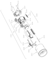
- FIG. 2 is an exploded perspective view of the lens barrel of FIG. 1.
- FIG. 3 is an exploded perspective view of the second group unit included in the lens barrel of FIG. 2.
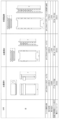
- FIG. 4A is a front view showing the magnetic circuit configuration of the lens drive unit of Embodiment 1, viewed from the optical axis direction.
- FIG. 4B is a plan view showing the magnetic circuit configuration of the lens drive unit of Embodiment 1.
- FIG. 4C is a side view showing the magnetic circuit configuration of the lens drive unit of Embodiment 1.
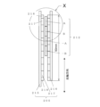
- FIG. 5 is an enlarged view of the X section in FIG. 4C.
- FIG. 4A is a front view showing the magnetic circuit configuration of the lens drive unit of Embodiment 1, viewed from the optical axis direction.
- FIG. 4B is a plan view showing the magnetic circuit configuration of the lens drive unit of Embodiment 1.
- FIG. 4C is a
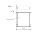
- FIG. 6A is a front view showing the magnetic circuit configuration of the voice coil motor of Comparative Example 1, viewed from the optical axis direction.
- FIG. 6B is a plan view showing the magnetic circuit configuration of the voice coil motor of Comparative Example 1.
- FIG. 6C is a side view showing the magnetic circuit configuration of the voice coil motor of Comparative Example 1.
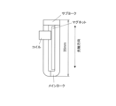
- FIG. 7A is a front view showing the magnetic circuit configuration of the lens drive unit of Comparative Example 2 (Prior Document 1) as viewed from the optical axis direction.
- FIG. 7B is a plan view showing the magnetic circuit configuration of the lens drive unit of Comparative Example 2 (Prior Document 1).
- FIG. 7C is a side view showing the magnetic circuit configuration of the lens drive unit of Comparative Example 2 (Prior Document 1).
- FIG. 8 is a diagram comparing characteristics of lens drive units.
- FIG. 9 is a diagram comparing characteristics of lens drive units.
- FIG. 10 is an explanatory diagram showing the dynamic balance of the two-group lens unit of FIG. 3 as viewed from the optical axis direction.
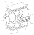
- FIG. 11 is a perspective view showing the configuration of a lens drive unit according to the second embodiment.
- FIG. 12 is an exploded perspective view of the lens drive unit of FIG. 11.
- FIG. 13 is a cross-sectional view of the lens drive unit of FIG. 11.
- FIG. 14 is a perspective view illustrating a case where a plurality of coils are used in a conventional voice coil motor.
- FIG. 1 is a perspective view showing an outline of the configuration of a lens barrel 100 according to the first embodiment.
- FIG. 2 is an exploded perspective view of the lens barrel 100 according to this embodiment.
- the lens barrel 100 is a lens barrel for an interchangeable lens camera, and is detachably attached to a camera body (not shown).
- the lens barrel 100 includes an exterior unit 101, a first group unit 102, a second group unit 103, an aperture unit 104, a third group unit 105, a fourth group unit 106, a circuit board unit 107, and a lens mount unit 108. It is equipped with
- the exterior unit 101 is a substantially cylindrical member that forms the outer shell of the lens barrel 100, and is disposed on the outermost side.
- the first group unit 102 is a substantially cylindrical member, includes a first group lens, and is disposed on the inner peripheral surface side of the exterior unit 101.
- the second group unit 103 is a substantially cylindrical member that holds a focus lens, and is a lens drive unit 10 (see FIG. 3) for driving a focus lens 209 (see FIG. 3), which will be described later, back and forth in the optical axis direction. It is equipped with The second group unit 103 is arranged on the inner peripheral surface side of the exterior unit 101.
- the diaphragm unit 104 is a substantially annular member, and is configured to drive movable blades to change the area of the aperture to adjust the amount of light that passes through the lens portion of the lens barrel 100. It is provided between the group unit 103 and the third group unit 105.
- the third group unit 105 is a substantially cylindrical member that holds an image stabilization lens, and drives the image stabilization lens in a plane perpendicular to the optical axis.
- the third group unit 105 is arranged on the inner peripheral surface side of the exterior unit 101.
- the fourth group unit 106 is a substantially cylindrical member that holds a fixed lens, and is arranged on the inner peripheral surface side of the exterior unit 101.
- the circuit board unit 107 is a unit for driving the lens barrel 100, and includes a printed circuit board on which electrical components, electrical contacts, and the like are mounted.
- the circuit board unit 107 is housed in a space between the image plane side of the third group unit 105, the outer periphery of the fourth group unit 106, and the inner periphery of the exterior unit 101.
- the lens mount unit 108 is a connecting component for connecting and fixing the lens barrel 100 to a camera body (not shown), and is fixed to the end surface of the exterior unit 101 on the image plane side.
- FIG. 3 is an exploded perspective view of the second group unit 103.
- the second group unit 103 includes, from the subject side to the image plane side, a fixed frame 201, a main shaft 202, a sub shaft 203, a flexible printed circuit board 204, a field unit 205, a focus lens unit 206, and a holding frame 201.
- a frame 207 is provided.
- the fixed frame 201 is a substantially annular member disposed closest to the subject side of the second group unit 103, and includes a main shaft 202, a sub-shaft 203, and a field unit (first field section, second field section). Hold the end of 205 on the subject side.
- An MR (Magneto Resistive) sensor 208 is connected to the flexible printed circuit board 204 and is fixed in a state where it is wrapped around the outer periphery of the fixed frame 201 .
- the focus lens unit 206 includes a focus lens 209 , a focus lens frame (first moving frame) 210 , an MR (Magneto Resistive) magnet 211 , and a coil 212 .
- the focus lens 209 is fixed to the inner circumference of the focus lens frame 210.
- the MR magnet 211 is fixed to the outer periphery of the focus lens frame 210.
- the coils 212 are arranged on the outer periphery of the focus lens frame 210 for one field unit 205, with two sets of two phases (two coils) arranged side by side along the optical axis direction, for a total of four coils. Fixed. Further, two sets of four coils 212 are arranged at three locations on the outer peripheral surface of the focus lens frame 210 at approximately equal angular intervals in the circumferential direction. Therefore, in this embodiment, a total of 12 coils 212 in which two sets of two phases are provided at three locations are fixed to the outer periphery of the focus lens frame 210.
- the two-phase coil 212 is a coil in which electric wire is wound around a winding axis arranged along a direction perpendicular to the optical axis of the focus lens 209 with respect to the field unit 205.
- the main shaft 202 and the sub-shaft 203 are inserted into insertion holes 210b and 210c of the focus lens unit 206, respectively, and are arranged along the direction of the optical axis L.
- the main shaft 202 and the sub-shaft 203 guide movement of the focus lens unit 206 in the direction of the optical axis L.
- the ends of the main shaft 202, the sub-shaft 203, and the field unit 205 on the image plane side are fixed to the holding frame 207.
- the holding frame 207 is fixed to the fixed frame 201 using a plurality of screws 213. Thereby, the focus lens unit 206 is driven in the direction of the optical axis L along the main axis 202 and while its rotation about the main axis 202 is restricted by the sub-axis 203.
- the MR magnet 211 is an example of a position detection member that detects the position of the focus lens unit 206.
- the MR sensor 208 is an example of the position detection sensor described above.
- the MR magnet 211 is provided in the focus lens unit 206 so as to be placed near the MR sensor 208 in the assembled state. Therefore, when the focus lens unit 206 including the MR magnet 211 moves back and forth in the direction of the optical axis L, the MR sensor 208 detects a change in the magnetic field caused by a change in the relative position of the MR magnet 211 with respect to the MR sensor 208.
- an MR sensor is used as an example of a position detection sensor, but other position detection sensors such as a photocoupler may also be used.
- an MR magnet is used as an example of the position detection member, but other position detection members such as a reflective mirror may also be used.
- the coil 212 is a member constituting the lens drive unit 10, which will be described later, and is fixedly arranged on the focus lens frame 210, and is held in a state where it is inserted into a gap in the field unit 205 in the shooting state.
- (2-2) Configuration of Lens Drive Unit 10 Below, the configuration of the lens drive unit 10 including the field unit 205 and the coil 212 will be described in detail.
- the lens drive unit 10 is a device that drives the focus lens unit 206 back and forth in the direction of the optical axis L.
- the lens drive unit 10 is a device that drives the focus lens unit 206 back and forth in the direction of the optical axis L.
- only one field unit 205 and its corresponding coil 212 will be taken out and explained from among the three field units 205 and the corresponding coils 212 provided in the configuration of FIG. do.
- FIGS. 4A to 4C are three side views showing the configuration of the lens drive unit 10 according to the present embodiment, and FIG. 5 is an enlarged view of the X portion in FIG. 4C.
- Yoke A215 and yoke B216 are made by punching out iron sheet metal by press working.
- the yoke A215 and the yoke B216 are flat members, as shown in FIGS. 4A to 4C.
- the main magnet 217 and the sub magnet 218 are, for example, Nd-based sintered magnets, and are each magnetized as a single pole.
- the sub magnet 218 has a width in the optical axis direction that is half that of the main magnet.
- the field unit 205 has sub-magnets 218 at both ends in the optical axis direction, nine main magnets 217 between them, and the magnetization of the surface facing the coil 212 is N pole.
- the S poles are fixed to the yoke A215 and the yoke B216, respectively, so that the S poles are regularly arranged alternately.
- the coils 212 are arranged in the order of A phase, B phase, -A phase, and -B phase from the top in the paper of FIG. 4C.
- the coils A phase and -A phase are connected in series, and the coils B phase and -B phase are also connected in series.
- two or more sets of two-phase coils A phase and B phase (or -A phase, -B phase) are arranged along the optical axis direction for one field unit 205.
- the configuration is called a tandem configuration.
- the coil 212 becomes It receives Lorentz force and is driven in the direction of the optical axis. More specifically, since the field unit 205 is fixed to the fixed frame 201 side and the coil 212 is fixed to the focus lens unit 206 side, by energizing the coil 212, the focus lens unit 206 is moved relative to the fixed frame 201. is driven in the optical axis direction.
- FIGS. 6A to 6C Compare the characteristics of the conventional voice coil motor (Comparative Example 1) shown in FIG. and explain.
- FIG. 8 is a table comparing the characteristics of the lens drive unit 10 and Comparative Examples 1 and 2.
- the voice coil motor of Comparative Example 1 shown in FIGS. 6A to 6C and the lens drive unit of Comparative Example 2 shown in FIGS. This shows the case where the design is made so that the thrust is as high as possible within the range of combined values.
- the characteristics of the voice coil motor of Comparative Example 1 shown in FIGS. 6A to 6C and the lens drive unit of the basic configuration of Comparative Example 2 shown in FIGS. 7A to 7C will be compared.
- the voice coil motor of Comparative Example 1 shown in FIGS. 6A to 6C and the lens drive unit of the basic configuration of Comparative Example 2 shown in FIGS. 7A to 7C are as follows.
- the size of the field part is almost the same (thickness 10 mm, width 24 mm, length 35 mm).
- the field section is a section that includes a main yoke, a sub-yoke, and a magnet, and means a section that generates a fixed magnetic field (for generating Lorentz force in the coil).
- the voice coil motor of Comparative Example 1 has a coil protruding downward from the field part in the figure, so the voice coil motor of Comparative Example 1 is substantially smaller than the lens drive unit of the basic configuration of Comparative Example 2.
- the rotation is large.
- thrust as shown in Fig. 8, the maximum thrust of the voice coil motor of Comparative Example 1 is 0.68N, whereas the maximum thrust of the lens drive unit with the basic configuration of Comparative Example 2 is approximately 1.10N. 62% maximum thrust is large.
- the lens drive unit 10 of this embodiment shown in FIGS. 4A to 4C has a length (50 mm) in the optical axis direction of the lens of the basic configuration of Comparative Example 2. Compared to the drive unit (35 mm), it is longer in the optical axis direction by 15 mm, which is equivalent to three main magnets (two coils).
- the thrust as shown in FIG. 8, the lens drive unit of the basic configuration has a thrust of 1.10N, whereas the lens drive unit 10 of this embodiment has a thrust of 1.55N, which is approximately 41% higher. I can see that
- the lens drive unit 10 of this embodiment shown in FIGS. 4A to 4C employs a tandem configuration in which two or more two-phase coils are arranged in series for one field unit 205. Although it becomes a little longer in the optical axis direction, it shows that it is possible to increase the thrust while keeping other dimensions exactly the same. (2-4) Comparison of characteristics with a configuration in which a plurality of lens drive units 10 are provided The above describes the characteristics of a configuration in which a single lens drive unit 10 is used. The characteristics of the case will be explained.
- FIG. 9 is a table comparing characteristics when a plurality of lens drive units are used.
- the characteristics when two lens drive units having the basic configuration of Comparative Example 2 are used ("x2 configuration" in FIG. 9) will be briefly described. Normally, if you think about it simply, when you use two lens drive units, the thrust is likely to double, but if you use two of the same lens drive units in parallel, the power consumption will also double. .
- the power used inside the lens barrel is supplied from the camera body, but there is an upper limit to the power that can be supplied from the camera body to the lens barrel. There is also an upper limit to the amount of power that can be used for the lens drive unit. Therefore, in a lens barrel including two lens drive units, the power that can be supplied per lens drive unit is halved, and the thrust force is not doubled. Therefore, when comparing characteristics, it is appropriate to compare under conditions that include the total power consumption.
- FIG. 9 shows the results of comparing the characteristics when the coil winding specifications are adjusted so that the power consumed by the lens drive unit is constant.
- the maximum thrust is 1.55N, which is the same as that of the basic configuration of Comparative Example 2 (see the upper part of Figure 9). This is approximately 41% higher than the maximum thrust of 1.10N.
- the characteristics are the same as those of the lens drive unit 10 of the tandem configuration of the present embodiment shown in FIGS. 4A to 4C described in (2-3) above.
- the tandem configuration of this embodiment is different from that of Comparative Example 2.
- the length is 15 mm in the optical axis direction
- the projected area in the optical axis direction and the overall volume are significantly smaller.
- the amount of permanent magnets used in the tandem configuration of this embodiment is significantly smaller than that of the two basic configurations ( ⁇ 2 configuration) of Comparative Example 2, which is 71%.
- Rare earth metals such as Nd (neodymium) and Dy (dysprosium) are used in Nd-based sintered magnets. For this reason, the price per mass tends to be very high, but by reducing the amount of magnets used, the cost can be reduced even with a lens drive unit with the same output.
- the amount of yokes and permanent magnets with large specific gravity can be reduced, so that weight reduction is also possible.
- FIG. 9 when comparing the basic configuration as a comparative example and the configuration including three lens drive units 10 of the present embodiment (tandem x 3), the maximum thrust of the basic configuration is 1.10N, while the maximum thrust of the basic configuration is 1.10N. It can be seen that the configuration including three lens drive units 10 of this embodiment (tandem x 3) can generate a thrust of 2.67 N, which is approximately 2.4 times as large.
- this thrust reaches approximately 3.9 times the thrust of 0.68N of the voice coil motor alone in Comparative Example 1 shown in FIGS. 6A to 6C and FIG. 8.
- Thrust can be improved more than before. Therefore, it is possible to drive a lens having a large mass, which is difficult to drive in the conventional configuration, back and forth in the optical axis direction.
- a lens with a large mass usually refers to a lens that uses a plurality of lenses, such as the focus lens 209 shown in FIG. 3, rather than a single lens having a large mass.
- a lens with a large mass necessarily has a certain length in the optical axis direction in many cases. Therefore, when driving a lens with a large mass, it is easy to tolerate a certain length of the driving section in the optical axis direction.
- the lens drive unit 10 As described above, by making the lens drive unit 10 have a tandem configuration within the allowable range for the lens drive unit 10, and by having a configuration in which a plurality of lens drive units 10 are combined, the size of the lens barrel is limited. It is possible to provide a lens drive unit 10 that can drive a lens with a larger mass by effectively utilizing both the space in the circumferential direction around the optical axis and the space in the optical axis direction.
- Fig. 9 the configuration was explained in which 4 coils (2 sets of 2-phase coils) were used for one field unit as a tandem configuration, but 6 coils (2 sets of 2-phase coils) were used.
- a configuration may be used in which three or more sets are used.
- n-phase coil n is an integer of 2 or more
- a coil of three or more phases may be used as long as it is configured to be driven.
- a set of three coils are arranged in the optical axis direction and used for one field unit.
- the two-phase drive in which two coils are arranged along the optical axis direction for one field unit has a higher degree of freedom in design.
- (2-5) Points to keep in mind when using a configuration with multiple lens drive units 10
- the thrust can be improved and a lens with a larger mass can be used. It was shown that it can be driven.
- the lens unit (movable part) including the lens becomes heavy, the vibration of the movable part, especially the backlash caused by the clearance between the outer peripheral surface of the main shaft 202 and the inner peripheral surface of the insertion hole 210b of the focus lens frame 210. Since vibrations are likely to occur due to this, it is necessary to take measures to suppress vibrations.
- FIG. 10 is a diagram of the focus lens unit 206 of the first embodiment viewed from the subject side in the optical axis direction.
- the force applied to the focus lens unit 206 is equal to the thrust generated by the coils 212a, 212b, and 212c.
- the frictional force generated between the main shaft 202 and the focus lens frame 210 is dominant.
- the coils 212a, 212b, and 212c are equally arranged at three locations with the optical axis center C1 of the lens as the center, so the thrust center of the thrust generated by the coils 212a, 212b, and 212c is on the optical axis. It coincides with the center C1. Further, the frictional force generated between the main shaft 202 and the focus lens frame 210 is in a direction opposite to the thrust of the coils 212a, 212b, and 212c.
- the focus lens frame 210 is centered around the main axis 202 and the center of the thrust by the coils 212a, 212b, 212c. vibrates in a mode that vibrates back and forth in the optical axis direction.
- the inertial force that causes the focus lens unit 206 to remain in the same position becomes dominant.
- the focus lens unit 206 vibrates in a mode in which the thrust centers of the coils 212a, 212b, and 212c vibrate back and forth with the vicinity of the center of gravity G1 of the movable part as a fulcrum.
- the center of gravity G1 of the movable part is the position that is the center of gravity of all the members that constitute the movable part that is movable with respect to the fixed frame 201 such as the focus lens unit 206 including the focus lens frame 210 to which the focus lens 209 is fixed. It means.
- the fulcrum is any point between the movable part gravity center G1 and the main axis 202 on the plane passing through the movable part gravity center G1 and the main axis 202. It vibrates and rattles.
- the outer periphery is approximately cylindrical
- the inner periphery has the focus lens 209 at the center
- the main axis 202 and the sub axis 203 are arranged in the circumferential direction.
- MR sensor 208, MR magnet 211, and other components are arranged. Therefore, the locations where the field units 205a, 205b, 205c and the coils 212a, 212b, 212c are arranged are restricted.
- three field units 205a, 205b, and 205c are arranged at approximately equal angular intervals in the circumferential direction around the optical axis center C1 of the focus lens 209, and , other parts are placed.
- the field units 205a, 205b, 205c are arranged on both sides of the plane P1 passing through the center of gravity G1 of the movable part and the main axis 202. That is, as shown in FIG. 10, the field unit 205a and the field unit 205c are arranged on both sides of a plane P1 passing through the center of gravity G1 of the movable part and the main axis 202.
- the thrust centers of the coils 212a, 212b, and 212c can be brought closer to the plane P1 passing through the main shaft 202 and the center of gravity G1 of the movable part, which serves as the fulcrum of backlash vibration. Therefore, the thrust centers of the coils 212a, 212b, and 212c can be brought closer to the fulcrum of the rattling vibration, so that the rattling vibration can be effectively suppressed.
- the n-phase (two-phase) coils for one field unit 205 are sandwiched between the field units 205 from both sides in the radial direction. It is located.
- Embodiment 1 has been described using an example in which the technology of the present disclosure is applied to drive a lens with a large mass. However, the technology of the present disclosure is applicable not only to driving a lens with a large mass, but also to It is also effective when used for the purpose of
- FIG. 11 is a perspective view of the lens drive unit of the second embodiment.
- FIG. 12 is an exploded perspective view of the lens drive unit of the second embodiment.
- FIG. 13 is a perspective view of the lens drive unit of the second embodiment.
- FIG. 14 is an explanatory diagram when a plurality of coils are driven in a conventional voice coil motor as a comparative example.
- the lens drive unit of the second embodiment is similar to the first embodiment in that two sets of coils are used for one field unit.
- Embodiment 2 as shown in FIG. The difference is that the moving frame is fixed to the movable frame 210B and is independently driven and controlled.
- the A group lens unit 206A includes an A group lens 209A, an A group lens frame (first moving frame) 210A, and an A group coil 212A.
- the A group lens 209A is fixed to a lens frame 210A, as shown in FIG. 13.
- An A group coil 212A is fixed to the outer peripheral surface of the lens frame 210A.
- the B group lens unit 206B includes a B group lens 209B, a B group lens frame (second moving frame) 210B, and a B group coil 212B.
- the B group lens 209B is fixed to a lens frame 210B, as shown in FIG. 13.
- a group B coil 212B is fixed to the outer peripheral surface of the lens frame 210B.
- the main shaft 202A and the sub-shaft 203B are arranged along the direction of the optical axis L while being inserted into the insertion holes of the A group lens unit 206A and the B group lens unit 206B, respectively.
- the main axis 202A and the sub-axis 203B guide the movement of the A group lens unit 206A and the B group lens unit 206B in the direction of the optical axis L.
- two axes (main axis 202A and sub-axis 203B) are shared by two lens units (A group lens unit 206A and B group lens unit 206B).
- a group lens unit 206A and B group lens unit 206B This simplifies the configuration compared to a configuration in which two lens units are guided by separate axes, and the relative accuracy between the A group lens 209A and the B group lens 209B due to axis installation errors. Variations in (eccentricity, inclination) can be suppressed.
- FIG. 14 is an explanatory diagram when two coils are used in a conventional voice coil motor.
- the configuration is the same as that of the voice coil motor shown in FIGS. 6A to 6C, except that the main yoke 315 is provided with two coils 312A and 312B.
- the permanent magnet 317 and the main yoke 315 inevitably move toward the optical axis. lengthen in the direction.
- the main yoke 315 and the sub-yoke 316 are more likely to be magnetically saturated. Therefore, if the permanent magnet 317 is simply made longer in the optical axis direction, the performance of the permanent magnet 317 cannot be brought out, and the thrust force decreases.
- the coil 212A and the coil 212B are air-core coils, and each coil 212A and 212B influences the other coils. There is almost no problem, and the current flowing through each coil 212A, 212B can be easily controlled.
- Embodiment 2 even if the field unit 205 is lengthened in the optical axis direction, it is not affected by magnetic saturation, thereby avoiding a decrease in the thrust of the coils 212A and 212B. be able to. Furthermore, even when multiple sets of coils 212A and 212B are combined for one field unit 205, there is almost no interaction between the coils 212A and 212B, which provides the useful effect of facilitating control. .
- the lens unit to be driven is not limited to a focus lens unit including a focus lens, but may be other moving frames such as a zoom lens unit, an image blur correction unit, an aperture unit, etc.
- the lens drive unit of the present disclosure has the effect of being able to obtain the necessary thrust and drive the lens to the end of the lens drive range while achieving miniaturization, and is therefore widely applicable as an actuator for driving a lens. It is possible.
- Lens drive unit 100 Lens barrel 101 Exterior unit 102 1st group unit 103 2nd group unit 104 Aperture unit 105 3rd group unit 106 4th group unit 107 Board unit 108 Lens mount unit 201 Fixed frame 202, 202A Main shaft 203, 203B Subshaft 204 Flexible printed circuit board 205 Field unit (first and second field parts) 205A Field unit (first field part) 205B Field unit (third field part) 205C Field unit (second field part) 206, 206A, 206B Focus lens unit 207 Holding frame 208 MR sensor 209 Focus lens 209A A group lens 209B B group lens 210 Focus lens frame (first moving frame) 210A A group lens frame (first moving frame) 210B B group lens frame (second moving frame) 211 MR magnet 212, 212a, 212b Coil 212A Group A coil 212B Group B coil 213 Screw 215 Main yoke 216 Sub yoke 217 Main magnet 218 Sub magnet C1 Center of optical
Landscapes
- Physics & Mathematics (AREA)
- General Physics & Mathematics (AREA)
- Optics & Photonics (AREA)
- Engineering & Computer Science (AREA)
- General Engineering & Computer Science (AREA)
- Chemical & Material Sciences (AREA)
- Combustion & Propulsion (AREA)
- Electromagnetism (AREA)
- Power Engineering (AREA)
- Lens Barrels (AREA)
- Linear Motors (AREA)
Priority Applications (2)
| Application Number | Priority Date | Filing Date | Title |
|---|---|---|---|
| EP22931021.4A EP4492113A4 (en) | 2022-03-07 | 2022-11-25 | Lens drive unit and lens barrel equipped with same |
| US18/835,726 US20250138389A1 (en) | 2022-03-07 | 2022-11-25 | Lens drive unit and lens barrel equipped with same |
Applications Claiming Priority (2)
| Application Number | Priority Date | Filing Date | Title |
|---|---|---|---|
| JP2022-034289 | 2022-03-07 | ||
| JP2022034289A JP7762854B2 (ja) | 2022-03-07 | 2022-03-07 | レンズ駆動ユニットおよびこれを備えたレンズ鏡筒 |
Publications (1)
| Publication Number | Publication Date |
|---|---|
| WO2023171049A1 true WO2023171049A1 (ja) | 2023-09-14 |
Family
ID=87936614
Family Applications (1)
| Application Number | Title | Priority Date | Filing Date |
|---|---|---|---|
| PCT/JP2022/043574 Ceased WO2023171049A1 (ja) | 2022-03-07 | 2022-11-25 | レンズ駆動ユニットおよびこれを備えたレンズ鏡筒 |
Country Status (4)
| Country | Link |
|---|---|
| US (1) | US20250138389A1 (https=) |
| EP (1) | EP4492113A4 (https=) |
| JP (2) | JP7762854B2 (https=) |
| WO (1) | WO2023171049A1 (https=) |
Cited By (3)
| Publication number | Priority date | Publication date | Assignee | Title |
|---|---|---|---|---|
| WO2025104996A1 (ja) * | 2023-11-14 | 2025-05-22 | キヤノン株式会社 | レンズ駆動装置 |
| US20250251645A1 (en) * | 2024-02-06 | 2025-08-07 | Zhongshan Union Optech Research Institute Co., Ltd. | Voice coil motor and zoom lens |
| WO2026023237A1 (ja) * | 2024-07-22 | 2026-01-29 | パナソニックIpマネジメント株式会社 | レンズ駆動ユニットおよびこれを備えたレンズ鏡筒 |
Citations (6)
| Publication number | Priority date | Publication date | Assignee | Title |
|---|---|---|---|---|
| JPH01185157A (ja) * | 1988-01-12 | 1989-07-24 | Canon Inc | リニアモータ |
| JPH07120653A (ja) * | 1993-10-27 | 1995-05-12 | Sony Corp | 電磁駆動装置 |
| JP2004343853A (ja) * | 2003-05-14 | 2004-12-02 | Sony Corp | リニアアクチュエータ、レンズ駆動装置、及び撮像装置 |
| JP2006243769A (ja) * | 2006-06-16 | 2006-09-14 | Sony Corp | レンズ鏡筒 |
| JP2016114654A (ja) * | 2014-12-11 | 2016-06-23 | オリンパス株式会社 | レンズ駆動用リニアアクチュエーター |
| JP2019213433A (ja) | 2018-06-08 | 2019-12-12 | パナソニックIpマネジメント株式会社 | リニアモータおよびこれを備えたレンズ鏡筒、撮像装置 |
Family Cites Families (3)
| Publication number | Priority date | Publication date | Assignee | Title |
|---|---|---|---|---|
| JP3941314B2 (ja) * | 2000-01-14 | 2007-07-04 | 株式会社安川電機 | コアレスリニアモータ |
| JP2010112976A (ja) * | 2008-11-04 | 2010-05-20 | Nikon Corp | レンズ駆動装置、レンズ位置検出装置、及びそれらを用いた撮像装置 |
| JP5884240B2 (ja) * | 2012-04-18 | 2016-03-15 | 株式会社タムロン | リニアアクチュエータ、及びそれを備えたレンズユニット、カメラ |
-
2022
- 2022-03-07 JP JP2022034289A patent/JP7762854B2/ja active Active
- 2022-11-25 US US18/835,726 patent/US20250138389A1/en active Pending
- 2022-11-25 EP EP22931021.4A patent/EP4492113A4/en active Pending
- 2022-11-25 WO PCT/JP2022/043574 patent/WO2023171049A1/ja not_active Ceased
-
2025
- 2025-06-25 JP JP2025107186A patent/JP2025123553A/ja active Pending
Patent Citations (6)
| Publication number | Priority date | Publication date | Assignee | Title |
|---|---|---|---|---|
| JPH01185157A (ja) * | 1988-01-12 | 1989-07-24 | Canon Inc | リニアモータ |
| JPH07120653A (ja) * | 1993-10-27 | 1995-05-12 | Sony Corp | 電磁駆動装置 |
| JP2004343853A (ja) * | 2003-05-14 | 2004-12-02 | Sony Corp | リニアアクチュエータ、レンズ駆動装置、及び撮像装置 |
| JP2006243769A (ja) * | 2006-06-16 | 2006-09-14 | Sony Corp | レンズ鏡筒 |
| JP2016114654A (ja) * | 2014-12-11 | 2016-06-23 | オリンパス株式会社 | レンズ駆動用リニアアクチュエーター |
| JP2019213433A (ja) | 2018-06-08 | 2019-12-12 | パナソニックIpマネジメント株式会社 | リニアモータおよびこれを備えたレンズ鏡筒、撮像装置 |
Non-Patent Citations (1)
| Title |
|---|
| See also references of EP4492113A4 |
Cited By (3)
| Publication number | Priority date | Publication date | Assignee | Title |
|---|---|---|---|---|
| WO2025104996A1 (ja) * | 2023-11-14 | 2025-05-22 | キヤノン株式会社 | レンズ駆動装置 |
| US20250251645A1 (en) * | 2024-02-06 | 2025-08-07 | Zhongshan Union Optech Research Institute Co., Ltd. | Voice coil motor and zoom lens |
| WO2026023237A1 (ja) * | 2024-07-22 | 2026-01-29 | パナソニックIpマネジメント株式会社 | レンズ駆動ユニットおよびこれを備えたレンズ鏡筒 |
Also Published As
| Publication number | Publication date |
|---|---|
| EP4492113A1 (en) | 2025-01-15 |
| EP4492113A4 (en) | 2025-06-18 |
| JP7762854B2 (ja) | 2025-10-31 |
| JP2025123553A (ja) | 2025-08-22 |
| JP2023129928A (ja) | 2023-09-20 |
| US20250138389A1 (en) | 2025-05-01 |
Similar Documents
| Publication | Publication Date | Title |
|---|---|---|
| WO2023171049A1 (ja) | レンズ駆動ユニットおよびこれを備えたレンズ鏡筒 | |
| JP6601638B2 (ja) | レンズ駆動装置、オートフォーカスカメラ及びカメラ付きモバイル端末装置 | |
| US8648920B2 (en) | Electromagnetically driven device with shake suppression | |
| US8730598B2 (en) | Driving device for a lens assembly | |
| US20150131153A1 (en) | Lens drive device | |
| JP2012008379A (ja) | レンズ駆動装置、オートフォーカスカメラ及びカメラ付きモバイル端末装置 | |
| US20090195878A1 (en) | Linear swing actuator | |
| JP2013033179A (ja) | レンズ駆動装置、オートフォーカスカメラ及びカメラ付き携帯端末装置 | |
| JP2011090064A (ja) | レンズ駆動装置、オートフォーカスカメラ及びカメラ付き携帯電話 | |
| JP7591770B2 (ja) | レンズ鏡筒、撮像装置 | |
| JP6021459B2 (ja) | ステッピングモータ、レンズ装置、および、撮像装置 | |
| CN110323919A (zh) | 一种基于正应力电磁驱动的微定位装置 | |
| JP2011242509A (ja) | レンズ駆動装置、オートフォーカスカメラ及びカメラ付きモバイル端末装置 | |
| JP2011085754A (ja) | 像振れ補正装置 | |
| JP2011128529A (ja) | レンズ駆動装置、オートフォーカスカメラ及びカメラ付き携帯電話 | |
| JP2013068702A (ja) | レンズ駆動装置、オートフォーカスカメラ及びカメラ付きモバイル端末 | |
| JP2006162876A (ja) | 駆動装置およびそれを用いたレンズ駆動装置 | |
| JP2006259032A (ja) | レンズ駆動装置 | |
| JP2009282127A (ja) | 光学装置 | |
| JP2011247958A (ja) | レンズ駆動装置、オートフォーカスカメラ及びカメラ付きモバイル端末装置 | |
| JP2023015903A (ja) | 回転往復駆動アクチュエーター | |
| JP2025080717A (ja) | レンズ駆動装置 | |
| JP2024115820A (ja) | レンズ駆動装置およびこれを備えたレンズ鏡筒 | |
| KR100723917B1 (ko) | Vcm 액츄에이터 및 그 틸트 보정방법 | |
| CN115549425A (zh) | 旋转往复驱动致动器 |
Legal Events
| Date | Code | Title | Description |
|---|---|---|---|
| 121 | Ep: the epo has been informed by wipo that ep was designated in this application |
Ref document number: 22931021 Country of ref document: EP Kind code of ref document: A1 |
|
| WWE | Wipo information: entry into national phase |
Ref document number: 18835726 Country of ref document: US |
|
| WWE | Wipo information: entry into national phase |
Ref document number: 2022931021 Country of ref document: EP |
|
| NENP | Non-entry into the national phase |
Ref country code: DE |
|
| ENP | Entry into the national phase |
Ref document number: 2022931021 Country of ref document: EP Effective date: 20241007 |
|
| WWP | Wipo information: published in national office |
Ref document number: 18835726 Country of ref document: US |