WO2023170725A1 - 室外機 - Google Patents
室外機 Download PDFInfo
- Publication number
- WO2023170725A1 WO2023170725A1 PCT/JP2022/009582 JP2022009582W WO2023170725A1 WO 2023170725 A1 WO2023170725 A1 WO 2023170725A1 JP 2022009582 W JP2022009582 W JP 2022009582W WO 2023170725 A1 WO2023170725 A1 WO 2023170725A1
- Authority
- WO
- WIPO (PCT)
- Prior art keywords
- side plate
- thermistor
- outdoor unit
- plate portion
- heat exchanger
- Prior art date
- Legal status (The legal status is an assumption and is not a legal conclusion. Google has not performed a legal analysis and makes no representation as to the accuracy of the status listed.)
- Ceased
Links
Images




Classifications
-
- F—MECHANICAL ENGINEERING; LIGHTING; HEATING; WEAPONS; BLASTING
- F24—HEATING; RANGES; VENTILATING
- F24F—AIR-CONDITIONING; AIR-HUMIDIFICATION; VENTILATION; USE OF AIR CURRENTS FOR SCREENING
- F24F1/00—Room units for air-conditioning, e.g. separate or self-contained units or units receiving primary air from a central station
- F24F1/06—Separate outdoor units, e.g. outdoor unit to be linked to a separate room comprising a compressor and a heat exchanger
- F24F1/20—Electric components for separate outdoor units
- F24F1/22—Arrangement or mounting thereof
-
- F—MECHANICAL ENGINEERING; LIGHTING; HEATING; WEAPONS; BLASTING
- F24—HEATING; RANGES; VENTILATING
- F24F—AIR-CONDITIONING; AIR-HUMIDIFICATION; VENTILATION; USE OF AIR CURRENTS FOR SCREENING
- F24F1/00—Room units for air-conditioning, e.g. separate or self-contained units or units receiving primary air from a central station
- F24F1/06—Separate outdoor units, e.g. outdoor unit to be linked to a separate room comprising a compressor and a heat exchanger
- F24F1/56—Casing or covers of separate outdoor units, e.g. fan guards
Definitions
- the present disclosure relates to an outdoor unit.
- Patent Document 1 discloses an outdoor unit that includes a heat exchanger and a casing that houses the heat exchanger.
- the housing of the outdoor unit is provided with a holding part that holds a thermistor for measuring the temperature of outside air.
- the thermistor is used to control the operation of the outdoor unit to prevent condensation from forming inside the casing of the outdoor unit.
- the holding part is formed in a handhold part that is formed separately from an outer part (side plate part) that constitutes the side surface of the casing.
- the hand parts are assembled to the outer shell parts.
- the outdoor unit of Patent Document 1 has a problem in that since the outdoor unit has a large number of component parts for attaching the thermistor to the housing, the number of man-hours for assembling the outdoor unit is large and the assembly workability is poor. Furthermore, in the outdoor unit of Patent Document 1, the handhold parts are assembled to the outer shell part, and therefore, these assembly errors tend to increase the error in the position of the thermistor with respect to the outer shell part. That is, it is difficult to accurately position the thermistor. If the positional deviation of the thermistor becomes large, the operation control of the outdoor unit for preventing the occurrence of dew condensation may not be carried out correctly, which is not preferable.
- the present disclosure has been made in view of the above-mentioned circumstances, and aims to provide an outdoor unit that can reduce the number of steps for assembling the outdoor unit, improve assembly workability, and that can accurately position the thermistor. Make it one of the objectives.
- One aspect of the outdoor unit according to the present disclosure includes a heat exchanger and a casing that accommodates the heat exchanger, and the casing includes a base on which the heat exchanger is placed, and an upper part from the base. and a side plate portion extending to the side plate portion, the side plate portion being made of resin, and a holding portion for holding the thermistor being integrally molded in the side plate portion.
- FIG. 2 is a view from above of the main parts of the outdoor unit in the embodiment.
- FIG. 2 is a perspective view showing a main part of a side plate part in an embodiment, and a perspective view showing a state in which a thermistor is held in a holding part formed in the side plate part. It is a figure showing typically a holding part in an embodiment.
- 7 is a cross-sectional view showing essential parts of the outdoor unit in the embodiment, and is a cross-sectional view taken along the line IX-IX in FIG. 6.
- the drawings appropriately indicate an X axis, a Y axis, and a Z axis.
- the X-axis indicates one of the horizontal directions.
- the Y axis indicates the other horizontal direction.
- the Z axis indicates the vertical direction.
- the horizontal direction along the X-axis will be referred to as the "front-back direction X”
- the horizontal direction along the Y-axis will be referred to as the "left-right direction Y”
- the vertical direction will be referred to as the "up-down direction Z.”
- the front-rear direction X, the left-right direction Y, and the up-down direction Z are directions that are orthogonal to each other.
- the front-back direction X is the front-back direction of the outdoor unit 1, which will be described later
- the left-right direction Y is the left-right direction of the outdoor unit 1.
- the side of the front-rear direction do.
- the left-right direction Y is the left-right direction when the outdoor unit 1, which will be described later, is viewed from the front (+X direction).
- the side of the left-right direction Y that the Y-axis arrow points to (+Y side) is the right side
- the side of the left-right direction Y that is opposite to the side that the Y-axis arrow points to (-Y side) is the left side.
- FIG. 1 is a perspective view showing an outdoor unit 1 in an embodiment.
- FIG. 2 is an exploded perspective view showing the outdoor unit 1.
- FIG. 3 is a perspective view showing a part of the outdoor unit 1.
- the outdoor unit 1 is, for example, an outdoor unit of an air conditioner.
- the outdoor unit 1 has a substantially rectangular parallelepiped shape.
- the outdoor unit 1 in this embodiment has a substantially rectangular parallelepiped shape that is long in the left-right direction Y when viewed in the up-down direction Z.
- the outdoor unit 1 includes a housing 2, a heat exchanger 3, a blower 4, a compressor 5, and an electrical box 6.
- the housing 2 houses a heat exchanger 3, a blower 4, a compressor 5, and an electrical box 6 inside.
- the housing 2 has a substantially rectangular parallelepiped box shape that is long in the left-right direction Y when viewed in the up-down direction Z.
- the housing 2 includes a base 21, a side plate portion 22, and a top plate portion 23.
- the base 21 constitutes the bottom of the housing 2, and has a substantially rectangular plate shape that is long in the left-right direction Y when viewed in the up-down direction Z.
- a heat exchanger 3, a blower 4, and a compressor 5 are placed on the base 21.
- an electrical component box 6 is arranged above the base 21.
- the side plate portion 22 extends upward from the base 21 and laterally surrounds the heat exchanger 3, blower 4, compressor 5, and electrical box 6 arranged on the base 21.
- the side plate portion 22 includes a front side plate portion 22A, a rear side plate portion 22B, a left side plate portion 22C, and a right side plate portion 22D.
- the front side plate part 22A and the rear side plate part 22B are lined up in the front-rear direction X.
- the front plate portion 22A is located on the front side (+X side) of the heat exchanger 3, blower 4, compressor 5, and electrical box 6 arranged on the base 21.
- a suction port 221 penetrating in the front-rear direction X is formed in the front side plate portion 22A.
- the rear plate portion 22B is located on the rear side ( ⁇ X side) of the heat exchanger 3, blower 4, compressor 5, and electrical box 6 arranged on the base 21.
- a discharge port 222 penetrating in the front-rear direction X is formed in the rear side plate portion 22B.
- the left side plate portion 22C and the right side plate portion 22D are aligned in the left-right direction Y.
- the left side plate portion 22C is located on the left side ( ⁇ Y side) of the heat exchanger 3, blower 4, compressor 5, and electrical box 6 arranged on the base 21.
- the right side plate portion 22D is located on the right side (+Y side) of the heat exchanger 3, blower 4, compressor 5, and electrical box 6 arranged on the base 21.
- FIG. 4 is a perspective view showing a part of the side plate portion 22.
- a vent hole 223 penetrating in the left-right direction Y is formed in the right side plate portion 22D.
- the vent 223 penetrates inside and outside of the housing 2 .
- a plurality of ventilation holes 223 are formed in the right side plate portion 22D.
- the right side plate portion 22D is made of resin. That is, the right side plate portion 22D is a resin molded product.
- a handhold portion 224 for transportation is formed on the right side plate portion 22D.
- the handhold portion 224 is a portion on which the worker's fingers are hooked when the worker transports the outdoor unit 1.
- the handhold portion 224 is recessed from the outside (+Y side) of the right side plate portion 22D.
- the handhold portion 224 is located at the upper part of the right side plate portion 22D.
- the handhold portion 224 is integrally molded with the right side plate portion 22D by resin molding.
- FIG. 5 is a perspective view showing the main parts of the side plate part 22 in the embodiment, and is a perspective view of the periphery of the handhold part 224 viewed from inside the right side plate part 22D.
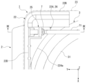
- FIG. 6 is a diagram of the main parts of the outdoor unit 1 viewed from above. As shown in FIG. 5, the handhold portion 224 protrudes inside (-Y side) of the right side plate portion 22D. The handhold portion 224 is located at the rear end portion of the upper portion of the right side plate portion 22D near the rear side plate portion 22B.
- the handhold portion 224 is located adjacent to the right side (+Y side) of the upper portion of the heat exchanger 3, which will be described later.
- a surface 224a of the handhold portion 224 facing the heat exchanger 3 is formed parallel to the heat exchanger 3.
- a surface 224a of the handhold portion 224 facing the heat exchanger 3 is curved to correspond to a curved portion 31 of the heat exchanger 3, which will be described later.
- a vent hole 225 that penetrates the inside and outside of the housing 2 is formed in the handle portion 224 of the right side plate portion 22D.
- the vent 225 is open to a surface 224a of the handle portion 224 facing the heat exchanger 3.
- the front plate portion 22A is generally formed separately from the rear side plate portion 22B, the left side plate portion 22C, and the right side plate portion 22D. Moreover, the left side plate part 22C and the right side plate part 22D are formed separately. A part of the rear side plate part 22B is integrally formed in the left side plate part 22C and the right side plate part 22D, respectively.
- the top plate portion 23 of the housing 2 has a substantially rectangular plate shape that is long in the left-right direction Y when viewed in the up-down direction Z.
- the top plate part 23 is arranged so as to close the upper opening of the side plate part 22. Thereby, the top plate portion 23 covers the heat exchanger 3, the blower 4, the compressor 5, and the electrical box 6 arranged on the base 21 from above.
- the heat exchanger 3 shown in FIGS. 2 and 3 performs heat exchange between the refrigerant flowing inside the heat exchanger 3 and the air passing through the heat exchanger 3.
- Heat exchanger 3 functions, for example, as an evaporator or a condenser.
- the heat exchanger 3 is formed in a plate shape along the rear side plate part 22B and the right side plate part 22D.
- a portion of the heat exchanger 3 along the rear plate portion 22B is exposed to the rear side of the housing 2 through the discharge port 222 of the rear plate portion 22B.
- a portion of the heat exchanger 3 along the right side plate 22D is exposed to the right side of the housing 2 through the vents 223, 225 of the right side plate 22D.
- the heat exchanger 3 has a curved portion 31 that is curved at 90 degrees at a corner between the rear side plate portion 22B and the right side plate portion 22D when viewed in the vertical direction Z.
- the blower 4 sends air to the heat exchanger 3.
- the blower 4 of this embodiment is constituted by a propeller fan.
- the blower 4 is located inside the front plate portion 22A so as to face the suction port 221 in the front-rear direction X.
- the blower 4 generates a flow of air that sucks outside air into the housing 2 through the suction port 221 and discharges it to the outside of the housing 2 through the discharge port 222 .
- the electrical equipment box 6 includes a power supply circuit that supplies power to each part of the outdoor unit 1 and a control circuit that controls the operation of the outdoor unit 1.
- FIG. 7 is a perspective view showing a main part of the side plate part 22, and is a perspective view showing a state in which the thermistor 7 is held in a holding part 25, which will be described later, formed in the side plate part.
- the outdoor unit 1 includes a thermistor 7 provided in the housing 2.
- the thermistor 7 of this embodiment has an elongated cylindrical appearance in which the axial dimension is larger than the radial dimension. Note that the appearance of the thermistor 7 is not limited to this, and may be arbitrary.
- Thermistor 7 measures the temperature of the outside air.
- the thermistor 7 is connected to the electrical component box 6 described above by a lead wire 71 (electrical wiring) extending from the thermistor 7.
- the thermistor 7 is used to control the operation of the outdoor unit 1 in order to prevent condensation from forming inside the housing 2 and from freezing the condensation.
- the outdoor unit 1 when the outdoor unit 1 is in heating operation, the inside of the casing 2 becomes warm, and the temperature difference between it and the cold outside air becomes large, causing the casing including the heat exchanger 3, etc. Condensation may occur inside the device, or the condensation may freeze.
- the electrical box 6 controls the operation of the outdoor unit 1 to temporarily heat the air. Switch from driving to cooling operation. This suppresses the occurrence of dew condensation inside the housing 2.
- FIG. 8 is a diagram schematically showing the holding part 25 provided in the outdoor unit 1.
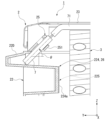
- FIG. 9 is a cross-sectional view showing essential parts of the outdoor unit 1, and is a cross-sectional view taken along the line IX--IX in FIG.
- the outdoor unit 1 includes a holding portion 25 that holds the thermistor 7 described above.
- the holding portion 25 is integrally formed with the side plate portion 22.
- the holding portion 25 is integrally molded with the right side plate portion 22D of the side plate portion 22 by resin molding.
- the position of the holding part 25 on the right side plate part 22D may be arbitrary.
- the holding part 25 is located at the upper part of the right side plate part 22D.
- the holding portion 25 is located at the rear end portion of the upper portion of the right side plate portion 22D near the rear side plate portion 22B.
- the holding portion 25 is arranged inside ( ⁇ Y side) of the right side plate portion 22D.
- the holding part 25 is located adjacent to the right side (+Y side) of the heat exchanger 3 with respect to the upper part of the heat exchanger 3. Therefore, the thermistor 7 held by the holding part 25 is located at the upper and rear end of the right side plate part 22D. Further, the thermistor 7 is located adjacent to the right side (+Y side) of the heat exchanger 3 with respect to the upper part of the heat exchanger 3.
- the holding portion 25 is configured such that the thermistor 7 is inserted in a direction that is inclined downward from the inside to the outside of the right side plate portion 22D in the horizontal direction.
- the holding part 25 is configured so that the thermistor 7 is inserted in the direction away from the heat exchanger 3 in the horizontal direction as it goes downward (-Z direction) on the outside of the heat exchanger 3.
- the holding part 25 is formed so that the thermistor 7 is inserted in a direction that is inclined downward (-Z direction) toward the right side (+Y side) inside the right side plate part 22D.
- the inclination angle ⁇ of the insertion direction of the thermistor 7 with respect to the left-right direction Y which is one of the horizontal directions, is 45 degrees, but it is not limited to this.
- the holding part 25 is formed so that the thermistor 7 formed in an elongated columnar shape is inserted in the axial direction thereof.
- the lead wire 71 extends toward the electrical component box 6 from the rear side in the insertion direction of the thermistor 7.
- the lead wire 71 extends from the thermistor 7 in a direction opposite to its insertion direction.
- the lead wire 71 is bendable.
- the holding portion 25 of this embodiment has claw portions 251 that sandwich the thermistor 7.
- the claw portion 251 is formed to be elastically deformable relative to the right side plate portion 22D.
- the claw portions 251 are elastically deformed to sandwich and hold the thermistor 7 by their elastic force.
- the direction in which the claw portions 251 are elastically deformed corresponds to the direction in which the claw portions 251 sandwich the thermistor 7 .
- the direction in which the claw portions 251 sandwich the thermistor 7 is a direction perpendicular to the direction in which the thermistor 7 is inserted into the holding portion 25 .
- the number of claw portions 251 may be one, for example, but is two in this embodiment.
- the two claw portions 251 can be elastically deformed in the direction in which they are arranged.
- the surface of the claw portion 251 that contacts the outer surface of the thermistor 7 corresponds to the shape of the outer surface of the thermistor 7 so as to make surface contact with the thermistor 7.
- the distance between the two claw parts 251 is smaller than the size of the part of the thermistor 7 inserted between these two claw parts 251. As a result, when the thermistor 7 is inserted between the two claws 251, the claws 251 are elastically deformed. The thermistor 7 is held by the elastic force of the claw portion 251 that is elastically deformed.
- a support section 26 that supports the thermistor 7 inserted into the holding section 25 from below (-Z side) is integrally formed on the right side plate section 22D. .
- the support part 26 is located below the holding part 25.
- the tip of the thermistor 7 inserted into the holding portion 25 in the insertion direction comes into contact with the support portion 26 .
- the support portion 26 of this embodiment is constituted by the handle portion 224 of the above-mentioned right side plate portion 22D. Therefore, the vent 225 of the handhold part 224 is located near the thermistor 7 inserted into the holding part 25.
- the holding portion 25 that holds the thermistor 7 is integrally formed on the right side plate portion 22D of the housing 2. Therefore, the number of parts of the outdoor unit 1 for attaching the thermistor 7 to the housing 2 can be reduced. Thereby, the number of man-hours required to assemble the outdoor unit 1 can be reduced, and the assembling workability can be improved.
- the holding part 25 is integrally formed with the right side plate part 22D, the error in the position of the thermistor 7 with respect to the right side plate part 22D can be suppressed to a small value. That is, accurate positioning of the thermistor 7 can be easily performed. This makes it possible to more reliably and correctly control the operation of the outdoor unit 1 to prevent the occurrence of dew condensation.
- the holding portion 25 is configured such that the thermistor 7 is inserted in a direction that is inclined downward from the inside to the outside of the right side plate portion 22D in the horizontal direction. Therefore, the load on the lead wire 71 can be reduced while preventing the lead wire 71 extending from the rear side in the insertion direction of the thermistor 7 from interfering with the top plate portion 23 of the housing 2. This point will be explained below.
- the lead wire 71 extends from the rear side of the thermistor 7 in a direction opposite to the direction in which the thermistor 7 is inserted. Therefore, when the insertion direction of the thermistor 7 is downward (-Z direction), the lead wire 71 extends upward (+Z direction) from the thermistor 7 and interferes with the top plate part 23 of the housing 2. . Further, in order to avoid interference between the lead wire 71 and the top plate portion 23, the angle at which the lead wire 71 is bent needs to be as large as, for example, 90 degrees. In this case, the load applied to the lead wire 71 becomes large.
- the insertion direction of the thermistor 7 is inclined with respect to the vertical direction Z, it is possible to suppress the lead wire 71 from interfering with the top plate portion 23 of the housing 2 . Further, in order to avoid interference between the lead wire 71 and the top plate portion 23, the angle at which the lead wire 71 is bent can be kept small. Therefore, the load on the lead wire 71 can be reduced.
- the insertion direction of the thermistor 7 into the holding part 25 is a direction that is inclined downward from the inside to the outside of the right side plate part 22D in the horizontal direction, so that the heat exchanger 3 can be inserted into the holding part in the horizontal direction. Even if the thermistor 7 is disposed near the holding portion 25 , insertion of the thermistor 7 into the holding portion 25 can be prevented from being obstructed by the heat exchanger 3 . This point will be explained below.
- the thermistor 7 When the holding part 25 is located between the inside of the right side plate part 22D and the heat exchanger 3 in the horizontal direction, and the holding part 25 is located near the heat exchanger 3 in the horizontal direction, the thermistor 7 is On the other hand, it is difficult to horizontally insert the right side plate portion 22D from the inside to the outside. On the other hand, as shown in FIG. 9, when the insertion direction of the thermistor 7 is inclined upward (+Z direction) with respect to the horizontal direction, the insertion of the thermistor 7 into the holding part 25 is inhibited by the heat exchanger 3. This can be suppressed.
- the thermistor 7 can be positioned in the insertion direction of the thermistor 7 by the support part 26 that supports the thermistor 7 inserted into the holding part 25 from below.
- the support portion 26, like the holding portion 25, is integrally formed with the right side plate portion 22D.
- the above-mentioned support portion 26 is constituted by a handhold portion 224 that is recessed from the outside of the right side plate portion 22D. That is, the support portion 26 also serves as the handhold portion 224. Thereby, the shape of the right side plate portion 22D can be simplified compared to the case where the support portion 26 is configured separately from the handhold portion 224.
- a vent hole 225 is formed in the handhold portion 224 forming the support portion 26. Further, a vent hole 223 is formed in the right side plate portion 22D. Outside air can be drawn into the housing 2 through these vents 223 and 225. The vent 225 of the handhold portion 224 is located near the thermistor 7 supported by the handhold portion 224 . Therefore, even if the thermistor 7 held by the holding part 25 is located inside the housing 2, the temperature of the outside air can be measured more accurately by the thermistor 7.
- the holding portion 25 has the claw portions 251 that sandwich the thermistor 7. Therefore, the thermistor 7 can be stably held by the elastic force of the elastically deformed claw portions 251.
- the holding part is not limited to being formed on the right side plate part, but may be formed integrally with, for example, any one of the front side plate part, the rear side plate part, and the left side plate part.
- the front side plate, the rear side plate, and the left side plate may be made of resin.
- the outdoor unit may be an outdoor unit of a refrigeration cycle device other than an air conditioner, such as a heat pump water heater.
Landscapes
- Engineering & Computer Science (AREA)
- Chemical & Material Sciences (AREA)
- Combustion & Propulsion (AREA)
- Mechanical Engineering (AREA)
- General Engineering & Computer Science (AREA)
- Other Air-Conditioning Systems (AREA)
Priority Applications (2)
| Application Number | Priority Date | Filing Date | Title |
|---|---|---|---|
| JP2024505653A JP7621551B2 (ja) | 2022-03-07 | 2022-03-07 | 室外機 |
| PCT/JP2022/009582 WO2023170725A1 (ja) | 2022-03-07 | 2022-03-07 | 室外機 |
Applications Claiming Priority (1)
| Application Number | Priority Date | Filing Date | Title |
|---|---|---|---|
| PCT/JP2022/009582 WO2023170725A1 (ja) | 2022-03-07 | 2022-03-07 | 室外機 |
Publications (1)
| Publication Number | Publication Date |
|---|---|
| WO2023170725A1 true WO2023170725A1 (ja) | 2023-09-14 |
Family
ID=87936352
Family Applications (1)
| Application Number | Title | Priority Date | Filing Date |
|---|---|---|---|
| PCT/JP2022/009582 Ceased WO2023170725A1 (ja) | 2022-03-07 | 2022-03-07 | 室外機 |
Country Status (2)
| Country | Link |
|---|---|
| JP (1) | JP7621551B2 (https=) |
| WO (1) | WO2023170725A1 (https=) |
Citations (4)
| Publication number | Priority date | Publication date | Assignee | Title |
|---|---|---|---|---|
| JPS511992U (https=) * | 1974-06-21 | 1976-01-08 | ||
| JPH07110142A (ja) * | 1993-08-20 | 1995-04-25 | Sharp Corp | 分離型空気調和機の室外ユニット |
| JPH09137966A (ja) * | 1995-11-14 | 1997-05-27 | Mitsubishi Electric Corp | 熱交換器装置 |
| CN212227246U (zh) * | 2020-03-24 | 2020-12-25 | 青岛海尔空调器有限总公司 | 用于空调室外机的温度传感器固定架以及空调室外机 |
Family Cites Families (2)
| Publication number | Priority date | Publication date | Assignee | Title |
|---|---|---|---|---|
| JPH041351U (https=) * | 1990-04-13 | 1992-01-08 | ||
| CN212252914U (zh) | 2020-03-24 | 2020-12-29 | 青岛海尔空调器有限总公司 | 用于空调室外机的温度传感器固定架以及空调室外机 |
-
2022
- 2022-03-07 JP JP2024505653A patent/JP7621551B2/ja active Active
- 2022-03-07 WO PCT/JP2022/009582 patent/WO2023170725A1/ja not_active Ceased
Patent Citations (4)
| Publication number | Priority date | Publication date | Assignee | Title |
|---|---|---|---|---|
| JPS511992U (https=) * | 1974-06-21 | 1976-01-08 | ||
| JPH07110142A (ja) * | 1993-08-20 | 1995-04-25 | Sharp Corp | 分離型空気調和機の室外ユニット |
| JPH09137966A (ja) * | 1995-11-14 | 1997-05-27 | Mitsubishi Electric Corp | 熱交換器装置 |
| CN212227246U (zh) * | 2020-03-24 | 2020-12-25 | 青岛海尔空调器有限总公司 | 用于空调室外机的温度传感器固定架以及空调室外机 |
Also Published As
| Publication number | Publication date |
|---|---|
| JP7621551B2 (ja) | 2025-01-24 |
| JPWO2023170725A1 (https=) | 2023-09-14 |
Similar Documents
| Publication | Publication Date | Title |
|---|---|---|
| CN104204688B (zh) | 空调装置的室内机 | |
| US10663180B2 (en) | Indoor unit for air-conditioning apparatus | |
| US20070006610A1 (en) | Outdoor unit of an air conditioner | |
| US20100226104A1 (en) | Electrical equipment assembly and outdoor unit of air conditioner disposed with the electrical equipment assembly | |
| WO2016136351A1 (ja) | 空気調和機の室外機 | |
| WO2023170725A1 (ja) | 室外機 | |
| JP5173403B2 (ja) | 空気調和機の室内機 | |
| KR101918589B1 (ko) | 차량용 통풍시트용 모터 모듈 | |
| US20240328663A1 (en) | Decorative panel and embedded ventilation fan including the same | |
| CN205119375U (zh) | 传感器装置及空调器室内机 | |
| CN203785126U (zh) | 空调机的室外机 | |
| CN216522295U (zh) | 面板部件及空调室内机 | |
| CN100436952C (zh) | 空调机的室内机 | |
| JP7837474B2 (ja) | 室内機、および空気調和機 | |
| JP2024137314A (ja) | 埋込形換気扇 | |
| KR102661220B1 (ko) | 실내기의 조립 구조 | |
| CN104094065B (zh) | 空调装置的室内机 | |
| CN209054652U (zh) | 空调机的室内机 | |
| JP2010151412A (ja) | 室外ユニットの開口カバー | |
| JP2017152100A (ja) | 電子回路装置、及び空気調和装置 | |
| CN223623191U (zh) | 冰箱及车辆 | |
| CN215409428U (zh) | 蜗壳组件和空调器 | |
| JP7785206B2 (ja) | 取付構造、室内機、および空気調和機 | |
| CN223024713U (zh) | 线控器 | |
| CN215809193U (zh) | 用于空调器的电控盒组件和空调器 |
Legal Events
| Date | Code | Title | Description |
|---|---|---|---|
| 121 | Ep: the epo has been informed by wipo that ep was designated in this application |
Ref document number: 22930711 Country of ref document: EP Kind code of ref document: A1 |
|
| WWE | Wipo information: entry into national phase |
Ref document number: 2024505653 Country of ref document: JP |
|
| NENP | Non-entry into the national phase |
Ref country code: DE |
|
| 122 | Ep: pct application non-entry in european phase |
Ref document number: 22930711 Country of ref document: EP Kind code of ref document: A1 |