WO2023167303A1 - 方向性電磁鋼板の製造方法 - Google Patents
方向性電磁鋼板の製造方法 Download PDFInfo
- Publication number
- WO2023167303A1 WO2023167303A1 PCT/JP2023/007916 JP2023007916W WO2023167303A1 WO 2023167303 A1 WO2023167303 A1 WO 2023167303A1 JP 2023007916 W JP2023007916 W JP 2023007916W WO 2023167303 A1 WO2023167303 A1 WO 2023167303A1
- Authority
- WO
- WIPO (PCT)
- Prior art keywords
- coil
- annealing
- steel sheet
- grain
- linear
- Prior art date
- Legal status (The legal status is an assumption and is not a legal conclusion. Google has not performed a legal analysis and makes no representation as to the accuracy of the status listed.)
- Ceased
Links
Images
Classifications
-
- C—CHEMISTRY; METALLURGY
- C21—METALLURGY OF IRON
- C21D—MODIFYING THE PHYSICAL STRUCTURE OF FERROUS METALS; GENERAL DEVICES FOR HEAT TREATMENT OF FERROUS OR NON-FERROUS METALS OR ALLOYS; MAKING METAL MALLEABLE, e.g. BY DECARBURISATION OR TEMPERING
- C21D9/00—Heat treatment, e.g. annealing, hardening, quenching or tempering, adapted for particular articles; Furnaces therefor
- C21D9/46—Heat treatment, e.g. annealing, hardening, quenching or tempering, adapted for particular articles; Furnaces therefor for sheet metals
-
- C—CHEMISTRY; METALLURGY
- C21—METALLURGY OF IRON
- C21D—MODIFYING THE PHYSICAL STRUCTURE OF FERROUS METALS; GENERAL DEVICES FOR HEAT TREATMENT OF FERROUS OR NON-FERROUS METALS OR ALLOYS; MAKING METAL MALLEABLE, e.g. BY DECARBURISATION OR TEMPERING
- C21D6/00—Heat treatment of ferrous alloys
- C21D6/008—Heat treatment of ferrous alloys containing Si
-
- C—CHEMISTRY; METALLURGY
- C21—METALLURGY OF IRON
- C21D—MODIFYING THE PHYSICAL STRUCTURE OF FERROUS METALS; GENERAL DEVICES FOR HEAT TREATMENT OF FERROUS OR NON-FERROUS METALS OR ALLOYS; MAKING METAL MALLEABLE, e.g. BY DECARBURISATION OR TEMPERING
- C21D8/00—Modifying the physical properties of ferrous metals or ferrous alloys by deformation combined with, or followed by, heat treatment
- C21D8/12—Modifying the physical properties of ferrous metals or ferrous alloys by deformation combined with, or followed by, heat treatment during manufacturing of articles with special electromagnetic properties
-
- C—CHEMISTRY; METALLURGY
- C21—METALLURGY OF IRON
- C21D—MODIFYING THE PHYSICAL STRUCTURE OF FERROUS METALS; GENERAL DEVICES FOR HEAT TREATMENT OF FERROUS OR NON-FERROUS METALS OR ALLOYS; MAKING METAL MALLEABLE, e.g. BY DECARBURISATION OR TEMPERING
- C21D8/00—Modifying the physical properties of ferrous metals or ferrous alloys by deformation combined with, or followed by, heat treatment
- C21D8/12—Modifying the physical properties of ferrous metals or ferrous alloys by deformation combined with, or followed by, heat treatment during manufacturing of articles with special electromagnetic properties
- C21D8/1216—Modifying the physical properties of ferrous metals or ferrous alloys by deformation combined with, or followed by, heat treatment during manufacturing of articles with special electromagnetic properties characterised by the working steps
- C21D8/1222—Hot rolling
-
- C—CHEMISTRY; METALLURGY
- C21—METALLURGY OF IRON
- C21D—MODIFYING THE PHYSICAL STRUCTURE OF FERROUS METALS; GENERAL DEVICES FOR HEAT TREATMENT OF FERROUS OR NON-FERROUS METALS OR ALLOYS; MAKING METAL MALLEABLE, e.g. BY DECARBURISATION OR TEMPERING
- C21D8/00—Modifying the physical properties of ferrous metals or ferrous alloys by deformation combined with, or followed by, heat treatment
- C21D8/12—Modifying the physical properties of ferrous metals or ferrous alloys by deformation combined with, or followed by, heat treatment during manufacturing of articles with special electromagnetic properties
- C21D8/1216—Modifying the physical properties of ferrous metals or ferrous alloys by deformation combined with, or followed by, heat treatment during manufacturing of articles with special electromagnetic properties characterised by the working steps
- C21D8/1233—Cold rolling
-
- C—CHEMISTRY; METALLURGY
- C21—METALLURGY OF IRON
- C21D—MODIFYING THE PHYSICAL STRUCTURE OF FERROUS METALS; GENERAL DEVICES FOR HEAT TREATMENT OF FERROUS OR NON-FERROUS METALS OR ALLOYS; MAKING METAL MALLEABLE, e.g. BY DECARBURISATION OR TEMPERING
- C21D8/00—Modifying the physical properties of ferrous metals or ferrous alloys by deformation combined with, or followed by, heat treatment
- C21D8/12—Modifying the physical properties of ferrous metals or ferrous alloys by deformation combined with, or followed by, heat treatment during manufacturing of articles with special electromagnetic properties
- C21D8/1216—Modifying the physical properties of ferrous metals or ferrous alloys by deformation combined with, or followed by, heat treatment during manufacturing of articles with special electromagnetic properties characterised by the working steps
- C21D8/1238—Flattening; Dressing; Flexing
-
- C—CHEMISTRY; METALLURGY
- C21—METALLURGY OF IRON
- C21D—MODIFYING THE PHYSICAL STRUCTURE OF FERROUS METALS; GENERAL DEVICES FOR HEAT TREATMENT OF FERROUS OR NON-FERROUS METALS OR ALLOYS; MAKING METAL MALLEABLE, e.g. BY DECARBURISATION OR TEMPERING
- C21D8/00—Modifying the physical properties of ferrous metals or ferrous alloys by deformation combined with, or followed by, heat treatment
- C21D8/12—Modifying the physical properties of ferrous metals or ferrous alloys by deformation combined with, or followed by, heat treatment during manufacturing of articles with special electromagnetic properties
- C21D8/1244—Modifying the physical properties of ferrous metals or ferrous alloys by deformation combined with, or followed by, heat treatment during manufacturing of articles with special electromagnetic properties characterised by the heat treatment
- C21D8/1255—Modifying the physical properties of ferrous metals or ferrous alloys by deformation combined with, or followed by, heat treatment during manufacturing of articles with special electromagnetic properties characterised by the heat treatment with diffusion of elements, e.g. decarburising, nitriding
-
- C—CHEMISTRY; METALLURGY
- C21—METALLURGY OF IRON
- C21D—MODIFYING THE PHYSICAL STRUCTURE OF FERROUS METALS; GENERAL DEVICES FOR HEAT TREATMENT OF FERROUS OR NON-FERROUS METALS OR ALLOYS; MAKING METAL MALLEABLE, e.g. BY DECARBURISATION OR TEMPERING
- C21D8/00—Modifying the physical properties of ferrous metals or ferrous alloys by deformation combined with, or followed by, heat treatment
- C21D8/12—Modifying the physical properties of ferrous metals or ferrous alloys by deformation combined with, or followed by, heat treatment during manufacturing of articles with special electromagnetic properties
- C21D8/1244—Modifying the physical properties of ferrous metals or ferrous alloys by deformation combined with, or followed by, heat treatment during manufacturing of articles with special electromagnetic properties characterised by the heat treatment
- C21D8/1261—Modifying the physical properties of ferrous metals or ferrous alloys by deformation combined with, or followed by, heat treatment during manufacturing of articles with special electromagnetic properties characterised by the heat treatment following hot rolling
-
- C—CHEMISTRY; METALLURGY
- C21—METALLURGY OF IRON
- C21D—MODIFYING THE PHYSICAL STRUCTURE OF FERROUS METALS; GENERAL DEVICES FOR HEAT TREATMENT OF FERROUS OR NON-FERROUS METALS OR ALLOYS; MAKING METAL MALLEABLE, e.g. BY DECARBURISATION OR TEMPERING
- C21D8/00—Modifying the physical properties of ferrous metals or ferrous alloys by deformation combined with, or followed by, heat treatment
- C21D8/12—Modifying the physical properties of ferrous metals or ferrous alloys by deformation combined with, or followed by, heat treatment during manufacturing of articles with special electromagnetic properties
- C21D8/1244—Modifying the physical properties of ferrous metals or ferrous alloys by deformation combined with, or followed by, heat treatment during manufacturing of articles with special electromagnetic properties characterised by the heat treatment
- C21D8/1272—Final recrystallisation annealing
-
- H—ELECTRICITY
- H01—ELECTRIC ELEMENTS
- H01F—MAGNETS; INDUCTANCES; TRANSFORMERS; SELECTION OF MATERIALS FOR THEIR MAGNETIC PROPERTIES
- H01F1/00—Magnets or magnetic bodies characterised by the magnetic materials therefor; Selection of materials for their magnetic properties
- H01F1/01—Magnets or magnetic bodies characterised by the magnetic materials therefor; Selection of materials for their magnetic properties of inorganic materials
- H01F1/03—Magnets or magnetic bodies characterised by the magnetic materials therefor; Selection of materials for their magnetic properties of inorganic materials characterised by their coercivity
- H01F1/12—Magnets or magnetic bodies characterised by the magnetic materials therefor; Selection of materials for their magnetic properties of inorganic materials characterised by their coercivity of soft-magnetic materials
- H01F1/14—Magnets or magnetic bodies characterised by the magnetic materials therefor; Selection of materials for their magnetic properties of inorganic materials characterised by their coercivity of soft-magnetic materials metals or alloys
- H01F1/147—Alloys characterised by their composition
-
- C—CHEMISTRY; METALLURGY
- C22—METALLURGY; FERROUS OR NON-FERROUS ALLOYS; TREATMENT OF ALLOYS OR NON-FERROUS METALS
- C22C—ALLOYS
- C22C38/00—Ferrous alloys, e.g. steel alloys
-
- C—CHEMISTRY; METALLURGY
- C22—METALLURGY; FERROUS OR NON-FERROUS ALLOYS; TREATMENT OF ALLOYS OR NON-FERROUS METALS
- C22C—ALLOYS
- C22C38/00—Ferrous alloys, e.g. steel alloys
- C22C38/04—Ferrous alloys, e.g. steel alloys containing manganese
-
- C—CHEMISTRY; METALLURGY
- C22—METALLURGY; FERROUS OR NON-FERROUS ALLOYS; TREATMENT OF ALLOYS OR NON-FERROUS METALS
- C22C—ALLOYS
- C22C38/00—Ferrous alloys, e.g. steel alloys
- C22C38/60—Ferrous alloys, e.g. steel alloys containing lead, selenium, tellurium, or antimony, or more than 0.04% by weight of sulfur
-
- Y—GENERAL TAGGING OF NEW TECHNOLOGICAL DEVELOPMENTS; GENERAL TAGGING OF CROSS-SECTIONAL TECHNOLOGIES SPANNING OVER SEVERAL SECTIONS OF THE IPC; TECHNICAL SUBJECTS COVERED BY FORMER USPC CROSS-REFERENCE ART COLLECTIONS [XRACs] AND DIGESTS
- Y02—TECHNOLOGIES OR APPLICATIONS FOR MITIGATION OR ADAPTATION AGAINST CLIMATE CHANGE
- Y02P—CLIMATE CHANGE MITIGATION TECHNOLOGIES IN THE PRODUCTION OR PROCESSING OF GOODS
- Y02P10/00—Technologies related to metal processing
- Y02P10/20—Recycling
Definitions
- the present invention relates to a method for manufacturing a grain-oriented electrical steel sheet, and more particularly to a method for manufacturing a grain-oriented electrical steel sheet that can prevent the development of cracks that occur at the edges of the steel sheet during flattening annealing, so-called edge cracks.
- Grain-oriented electrical steel sheets are used as soft magnetic materials, mainly as iron core materials for transformers and rotating equipment, and are required to have high magnetic flux density, low core loss and low magnetostriction.
- a grain-oriented silicon steel sheet is a hot-rolled sheet obtained by hot-rolling a steel slab adjusted to a predetermined chemical composition. It is cold rolled for at least 10 times, then decarburized and annealed, then coated with an annealing separator, dried, wound into a coil under tension, and then finished annealed in a predetermined atmosphere. manufactured.
- the coil In the annealing furnace where the final annealing is performed, the coil is placed with its winding axis perpendicular to the surface of the coil cradle and exposed to high temperature and long time treatment. Therefore, defects frequently occur at the ends of the coil that are in contact with the coil cradle (hereinafter also referred to as edges).
- the most problematic defect that occurs at the ends of the coil is edge cracks caused by deformation of the edges.
- it is common to perform flattening annealing for flattening the coil and applying a coating. The possibility that the crack will further progress increases. If the edge cracks progress to a large extent, the steel sheet will break, which is a major impediment to productivity.
- JP-A-10-204542 Japanese Patent Application Laid-Open No. 2001-323322
- an object of the present invention is to provide a method for suppressing the progress of the cracked edge.
- a method for manufacturing a grain-oriented electrical steel sheet comprising the step of performing flattening annealing after that, When the coil is charged into a final annealing furnace, it is separated from the axial end of the coil in contact with the coil cradle of the final annealing furnace by 5 mm or more and 20 mm or less in the axial direction of the coil, and in a direction that traverses the axial direction.
- a linear region extending continuously or discontinuously from the steel plate surface is pressed by 5 ⁇ m to 30 ⁇ m, localized strain is applied, and then the finish annealing is performed,
- a method for producing a grain-oriented electrical steel sheet characterized by forming crystal grains having a misorientation angle of 15 degrees or more from Goss-oriented grains.
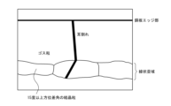
- FIG. 10 is a diagram showing suppression of the development of edge cracks in the strain introducing portion.
- a grain-oriented silicon steel sheet is a hot-rolled sheet obtained by hot-rolling a steel slab adjusted to a predetermined chemical composition. After cold rolling for 10 times or more, then after decarburization annealing, an annealing separator is applied, dried, wound into a coil while applying a winding tension, and the coil is subjected to finish annealing in a predetermined atmosphere. It is generally manufactured by
- the axial end of the coil that is in contact with the coil cradle of the finish annealing furnace is separated in the coil axial direction by 5 mm or more and 20 mm or less. Then, a linear region extending continuously or discontinuously in the direction transverse to the axial direction is locally strained (the amount of pushing from the steel sheet surface is 5 ⁇ m to 30 ⁇ m), and then finish annealing is applied to the line. It is characterized in that fine crystal grains other than Goss-oriented grains are generated in 50% or more of the total length of the strained region. Each step will be specifically described below.
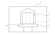
- a coil cradle 2 is arranged in the finish annealing furnace 1 .
- the coil 3 is placed on the coil holder 2 and subjected to final annealing.
- a linear region L that extends continuously or discontinuously in a direction transverse to the axial direction and is spaced from the coil end portion 30 on the side that is placed on the coil cradle 2 and contacts the cradle 2 in the coil axial direction by 5 mm or more and 20 mm or less. is given a local strain.
- the above-described local strain is applied to one end in the rolling direction, which is the coil end on the side in contact with the pedestal 2 .
- the linear region is defined as a region separated (hereinafter also referred to as "separation length") from the coil end (on the side in contact with the cradle) in the coil axial direction by 5 mm or more and 20 mm or less. That is, if the separation length is less than 5 mm, the effect of suppressing the propagation of edge cracks occurring at the edge is insufficient, while if the separation length exceeds 20 mm, the industrial yield is not sufficiently improved.
- the linear region is oriented transversely to the coil axial direction, preferably perpendicular to the coil axial direction.
- the linear area is preferably provided continuously, but may be discontinuous. In the case of discontinuity, it is desirable that the total length of the continuous portion is 80% or more of the total circumferential length of the coil perpendicular to the coil axial direction in order to obtain the strain introduction effect described later.
- strain introduction the method of applying strain to the linear region described above is not particularly limited as long as the strain is introduced, but for example, a method of pressing a roll or a needle with a sharp contact surface, among others, an abacus ball-shaped
- the method of strain introduction with cemented carbide rolls is advantageously suitable. At that time, it is important to partially press the steel plate surface to a depth of 5 ⁇ m to 30 ⁇ m in the thickness direction from the steel plate surface.
- the reason why the push amount is 5 ⁇ m to 30 ⁇ m is that if the push amount is less than 5 ⁇ m, the effect of suppressing the progress of edge cracks is small. because it is difficult.
- Linear strain region The steel strip subjected to the above processing is made into a coil, and the coil is placed on a coil cradle in an annealing furnace so that the linear strain region where strain is applied to the linear region is the coil lower end, and finished. Annealed. In the secondary recrystallization annealing of this final annealing, a secondary recrystallization structure due to Goss orientation grains is formed. At that time, in the above-mentioned linear strain region, recrystallization due to the introduced strain advances prior to secondary recrystallization, so even after secondary recrystallization occurs around the linear strain region, linear strain Fine recrystallized grains remain in the region.
- the linear strain region it is essential to generate crystal grains having an orientation difference of 15 degrees or more from the Goss orientation in 50% or more of the total length of the linear strain region (perimeter of the coil).
- the production of grains having a misorientation of 15 degrees or more from the Goss orientation in the linear strain region means recrystallization having a misorientation of 15 degrees or more from the Goss orientation grown by 1/2 or more in the thickness direction of the steel sheet. It means that such crystal grains are present over 50% or more of the entire length of the linear region (in the circumferential direction of the coil).
- it is necessary to set the indentation amount in the linear region to 5 ⁇ m to 30 ⁇ m.
- the average temperature increase rate in the region of 500° C. or higher and 800° C. or lower in the final annealing be 25° C./h or less.
- the lower limit of the average heating rate in the temperature range is not particularly limited, it can be, for example, 3° C./h or more.
- the fine crystal grains other than the Goss grains described above are present over 50% or more of the total length of the linear region, it is possible to effectively suppress the extension of edge cracks occurring in the edge portion into the interior of the linear region. That is, as shown schematically in Fig. 2, the structure from the steel plate edge to the linear region after secondary recrystallization annealing, edge cracks extending from the steel plate edge to the inside of the steel plate are the Goss grains generated in the strain introduction part. Fine crystal grains with orientations other than the direction block the development of edge cracks by dispersing the stress for edge crack development.
- Crystal grains having a misorientation angle of 15 degrees or more from the Goss-oriented grains preferably exist over 80% or more of the total length of the linear region, and may exist over 100% of the total length. More preferably, crystal grains having a misorientation angle of 15 degrees or more and 55 degrees or less from the Goss-oriented grains are present over 80% or more of the total length of the linear regions.
- At least one linear strain region is required, and two or more may be provided in the range of 5 to 20 mm from the coil end, and for example, 1 to 30 may be provided.
- the interval between the linear strain regions is preferably 0.5 mm or more, for example, the interval can be 0.5 to 15 mm.
- the present invention is applicable to any known grain-oriented electrical steel sheet because it can reliably prevent the development of edge cracks in the grain-oriented electrical steel sheet by introducing strain into the linear region.
- the chemical composition of the grain-oriented electrical steel sheet is also not particularly limited, but the chemical composition shown below can be employed.
- the reason for limiting the content of each component is as follows.
- C 0.01-0.1mass% If the content of C is less than 0.01%, there is a possibility that C may not sufficiently improve the structure. On the other hand, if the C content exceeds 0.1%, it may become difficult to remove C by decarburization annealing.
- Si 2.0-5.5 mass% Si is an element that increases the resistivity, which is the main function of electrical steel sheets. If the Si content is less than 2.0%, the increase in resistivity is not sufficient, and if it exceeds 5.5%, the cold rolling performance is poor and production becomes difficult. There is a possibility that it will become.
- Mn 0.02-2.5 mass% Mn has the effect of improving hot rolling properties. If it is less than 0.02%, the improvement effect is not sufficient. There is a risk that it will be disadvantageous in terms of sex.
- Al 0.01 to 0.04 mass% and N: 0.004 to 0.01 mass%, and if necessary, one or more of S and Se at 0.005 mass% or more 0.030 It can be contained in mass% or less.
- Al 0.003 to 0.01 mass%
- N 0.002 to 0.006 mass%
- S and Se each less than 0.005%
- a steel slab containing C: 0.06 mass%, Si: 3.2 mass%, Mn: 0.05 mass%, Al: 0.005 mass%, and N: 0.004 mass% was heated to 1200°C and then hot-rolled to a thickness of 2.5mm. After finishing to 0.19 mm, the steel sheet was annealed at 1000° C. for 60 seconds and finished to a thickness of 0.19 mm by cold rolling once. This cold-rolled sheet was decarburized and annealed in wet hydrogen at 820° C. for 120 seconds and wound into a coil.
- the number of edge cracks exceeding 8 mm in depth at the coil edge portion per 100 m and the maximum depth of the edge cracks that occurred were evaluated. Furthermore, the length ratio of grains having a misorientation angle of 15 degrees or more from the Goss-oriented grains in the linear strain region was investigated. That is, the length ratio of crystal grains was determined by linearly analyzing the crystal orientation using an Electron Back-Scattering Pattern (EBSP) apparatus in the longitudinal direction of the coil in the central portion of the linear strain region.
- EBSP Electron Back-Scattering Pattern
- the method for producing a grain-oriented electrical steel sheet of the present invention by introducing linear strain in the vicinity of the edge where edge cracks occur before secondary recrystallization, Goss-oriented grains and grains are formed in the strain-introduced portion in the final annealing. can generate different grains to prevent edge cracks from propagating inside Goss grains. As a result, it is possible to reduce edge cutting in the slitting process for the silicon steel sheet that has undergone the final process, and to improve the product yield, which is highly industrially useful.
Landscapes
- Chemical & Material Sciences (AREA)
- Engineering & Computer Science (AREA)
- Physics & Mathematics (AREA)
- Materials Engineering (AREA)
- Crystallography & Structural Chemistry (AREA)
- Mechanical Engineering (AREA)
- Thermal Sciences (AREA)
- Metallurgy (AREA)
- Organic Chemistry (AREA)
- Electromagnetism (AREA)
- Manufacturing & Machinery (AREA)
- Dispersion Chemistry (AREA)
- Power Engineering (AREA)
- Manufacturing Of Steel Electrode Plates (AREA)
Priority Applications (2)
| Application Number | Priority Date | Filing Date | Title |
|---|---|---|---|
| US18/838,042 US20250146096A1 (en) | 2022-03-02 | 2023-03-02 | Method of producing grain-oriented electrical steel sheet |
| JP2023547283A JP7673814B2 (ja) | 2022-03-02 | 2023-03-02 | 方向性電磁鋼板の製造方法 |
Applications Claiming Priority (2)
| Application Number | Priority Date | Filing Date | Title |
|---|---|---|---|
| JP2022-032047 | 2022-03-02 | ||
| JP2022032047 | 2022-03-02 |
Publications (1)
| Publication Number | Publication Date |
|---|---|
| WO2023167303A1 true WO2023167303A1 (ja) | 2023-09-07 |
Family
ID=87883872
Family Applications (1)
| Application Number | Title | Priority Date | Filing Date |
|---|---|---|---|
| PCT/JP2023/007916 Ceased WO2023167303A1 (ja) | 2022-03-02 | 2023-03-02 | 方向性電磁鋼板の製造方法 |
Country Status (3)
| Country | Link |
|---|---|
| US (1) | US20250146096A1 (https=) |
| JP (1) | JP7673814B2 (https=) |
| WO (1) | WO2023167303A1 (https=) |
Citations (7)
| Publication number | Priority date | Publication date | Assignee | Title |
|---|---|---|---|---|
| JPS63100131A (ja) * | 1986-10-17 | 1988-05-02 | Nippon Steel Corp | 珪素鋼板の仕上焼鈍方法 |
| JPS6442530A (en) * | 1987-08-07 | 1989-02-14 | Nippon Steel Corp | Box annealing method for strip coil |
| JP2000038616A (ja) * | 1998-07-24 | 2000-02-08 | Kawasaki Steel Corp | 側歪の少ない方向性けい素鋼板の製造方法 |
| JP2001323322A (ja) * | 2000-05-12 | 2001-11-22 | Kawasaki Steel Corp | 方向性珪素鋼帯の最終仕上げ焼鈍方法 |
| KR20030039583A (ko) * | 2001-11-13 | 2003-05-22 | 주식회사 포스코 | 생산성이 우수한 방향성 전기강판의 제조방법 |
| WO2014080763A1 (ja) * | 2012-11-26 | 2014-05-30 | 新日鐵住金株式会社 | 方向性電磁鋼板及び方向性電磁鋼板の製造方法 |
| JP2021025128A (ja) * | 2019-07-31 | 2021-02-22 | Jfeスチール株式会社 | 方向性電磁鋼板 |
-
2023
- 2023-03-02 US US18/838,042 patent/US20250146096A1/en active Pending
- 2023-03-02 WO PCT/JP2023/007916 patent/WO2023167303A1/ja not_active Ceased
- 2023-03-02 JP JP2023547283A patent/JP7673814B2/ja active Active
Patent Citations (7)
| Publication number | Priority date | Publication date | Assignee | Title |
|---|---|---|---|---|
| JPS63100131A (ja) * | 1986-10-17 | 1988-05-02 | Nippon Steel Corp | 珪素鋼板の仕上焼鈍方法 |
| JPS6442530A (en) * | 1987-08-07 | 1989-02-14 | Nippon Steel Corp | Box annealing method for strip coil |
| JP2000038616A (ja) * | 1998-07-24 | 2000-02-08 | Kawasaki Steel Corp | 側歪の少ない方向性けい素鋼板の製造方法 |
| JP2001323322A (ja) * | 2000-05-12 | 2001-11-22 | Kawasaki Steel Corp | 方向性珪素鋼帯の最終仕上げ焼鈍方法 |
| KR20030039583A (ko) * | 2001-11-13 | 2003-05-22 | 주식회사 포스코 | 생산성이 우수한 방향성 전기강판의 제조방법 |
| WO2014080763A1 (ja) * | 2012-11-26 | 2014-05-30 | 新日鐵住金株式会社 | 方向性電磁鋼板及び方向性電磁鋼板の製造方法 |
| JP2021025128A (ja) * | 2019-07-31 | 2021-02-22 | Jfeスチール株式会社 | 方向性電磁鋼板 |
Also Published As
| Publication number | Publication date |
|---|---|
| JP7673814B2 (ja) | 2025-05-09 |
| US20250146096A1 (en) | 2025-05-08 |
| JPWO2023167303A1 (https=) | 2023-09-07 |
Similar Documents
| Publication | Publication Date | Title |
|---|---|---|
| JP5610084B2 (ja) | 方向性電磁鋼板およびその製造方法 | |
| CN110651058B (zh) | 取向性电磁钢板及其制造方法 | |
| CN101311287B (zh) | 方向性电磁钢板 | |
| JP5835557B2 (ja) | 方向性電磁鋼板の製造方法 | |
| KR101498404B1 (ko) | 방향성 전기 강판의 제조 방법 | |
| US20150243419A1 (en) | Method for producing grain-oriented electrical steel sheet | |
| CN111411294A (zh) | 取向性电磁钢板 | |
| JP7338812B1 (ja) | 方向性電磁鋼板の製造方法 | |
| JP7028215B2 (ja) | 方向性電磁鋼板の製造方法 | |
| JP5287641B2 (ja) | 方向性電磁鋼板の製造方法 | |
| WO2023167303A1 (ja) | 方向性電磁鋼板の製造方法 | |
| JP3893759B2 (ja) | 方向性けい素鋼板の製造方法 | |
| JP5846390B2 (ja) | 方向性電磁鋼板の製造方法 | |
| CN117062921A (zh) | 取向性电磁钢板的制造方法 | |
| JP6143010B2 (ja) | 鉄損特性に優れる方向性電磁鋼板の製造方法 | |
| CN117203355A (zh) | 取向性电磁钢板的制造方法 | |
| JP5854236B2 (ja) | 方向性電磁鋼板の製造方法 | |
| EP4729640A1 (en) | Method for producing grain-oriented electrical steel sheet, and induction heating device | |
| JP7764851B2 (ja) | 方向性電磁鋼板およびその製造方法 | |
| EP4729639A1 (en) | Method for manufacturing oriented electromagnetic steel sheet, and induction heating device | |
| WO2026042535A1 (ja) | 優れた磁気特性を有する方向性電磁鋼板の製造方法 | |
| JP2025151626A (ja) | 方向性電磁鋼板の製造方法 | |
| JP2003027139A (ja) | 方向性電磁鋼板の製造方法 | |
| WO2025095089A1 (ja) | 方向性電磁鋼板の製造方法および製造設備 | |
| WO2026069986A1 (ja) | 方向性電磁鋼板用熱延板の製造方法、方向性電磁鋼板の製造方法、方向性電磁鋼板用熱延板の製造設備列、及び方向性電磁鋼板用熱延板 |
Legal Events
| Date | Code | Title | Description |
|---|---|---|---|
| WWE | Wipo information: entry into national phase |
Ref document number: 2023547283 Country of ref document: JP |
|
| 121 | Ep: the epo has been informed by wipo that ep was designated in this application |
Ref document number: 23763560 Country of ref document: EP Kind code of ref document: A1 |
|
| WWE | Wipo information: entry into national phase |
Ref document number: 202417052024 Country of ref document: IN |
|
| WWE | Wipo information: entry into national phase |
Ref document number: 18838042 Country of ref document: US |
|
| NENP | Non-entry into the national phase |
Ref country code: DE |
|
| 122 | Ep: pct application non-entry in european phase |
Ref document number: 23763560 Country of ref document: EP Kind code of ref document: A1 |
|
| WWP | Wipo information: published in national office |
Ref document number: 18838042 Country of ref document: US |