WO2023166933A1 - 防振装置および防振装置の製造方法 - Google Patents
防振装置および防振装置の製造方法 Download PDFInfo
- Publication number
- WO2023166933A1 WO2023166933A1 PCT/JP2023/004238 JP2023004238W WO2023166933A1 WO 2023166933 A1 WO2023166933 A1 WO 2023166933A1 JP 2023004238 W JP2023004238 W JP 2023004238W WO 2023166933 A1 WO2023166933 A1 WO 2023166933A1
- Authority
- WO
- WIPO (PCT)
- Prior art keywords
- fastening hole
- peripheral surface
- stopper
- shaft member
- ridges
- Prior art date
- Legal status (The legal status is an assumption and is not a legal conclusion. Google has not performed a legal analysis and makes no representation as to the accuracy of the status listed.)
- Ceased
Links
Images


Classifications
-
- F—MECHANICAL ENGINEERING; LIGHTING; HEATING; WEAPONS; BLASTING
- F16—ENGINEERING ELEMENTS AND UNITS; GENERAL MEASURES FOR PRODUCING AND MAINTAINING EFFECTIVE FUNCTIONING OF MACHINES OR INSTALLATIONS; THERMAL INSULATION IN GENERAL
- F16F—SPRINGS; SHOCK-ABSORBERS; MEANS FOR DAMPING VIBRATION
- F16F1/00—Springs
- F16F1/36—Springs made of rubber or other material having high internal friction, e.g. thermoplastic elastomers
- F16F1/42—Springs made of rubber or other material having high internal friction, e.g. thermoplastic elastomers characterised by the mode of stressing
- F16F1/52—Springs made of rubber or other material having high internal friction, e.g. thermoplastic elastomers characterised by the mode of stressing loaded in combined stresses
- F16F1/54—Springs made of rubber or other material having high internal friction, e.g. thermoplastic elastomers characterised by the mode of stressing loaded in combined stresses loaded in compression and shear
-
- F—MECHANICAL ENGINEERING; LIGHTING; HEATING; WEAPONS; BLASTING
- F16—ENGINEERING ELEMENTS AND UNITS; GENERAL MEASURES FOR PRODUCING AND MAINTAINING EFFECTIVE FUNCTIONING OF MACHINES OR INSTALLATIONS; THERMAL INSULATION IN GENERAL
- F16B—DEVICES FOR FASTENING OR SECURING CONSTRUCTIONAL ELEMENTS OR MACHINE PARTS TOGETHER, e.g. NAILS, BOLTS, CIRCLIPS, CLAMPS, CLIPS OR WEDGES; JOINTS OR JOINTING
- F16B33/00—Features common to bolt and nut
- F16B33/002—Means for preventing rotation of screw-threaded elements
-
- F—MECHANICAL ENGINEERING; LIGHTING; HEATING; WEAPONS; BLASTING
- F16—ENGINEERING ELEMENTS AND UNITS; GENERAL MEASURES FOR PRODUCING AND MAINTAINING EFFECTIVE FUNCTIONING OF MACHINES OR INSTALLATIONS; THERMAL INSULATION IN GENERAL
- F16B—DEVICES FOR FASTENING OR SECURING CONSTRUCTIONAL ELEMENTS OR MACHINE PARTS TOGETHER, e.g. NAILS, BOLTS, CIRCLIPS, CLAMPS, CLIPS OR WEDGES; JOINTS OR JOINTING
- F16B35/00—Screw-bolts; Stay-bolts; Screw-threaded studs; Screws; Set screws
- F16B35/04—Screw-bolts; Stay-bolts; Screw-threaded studs; Screws; Set screws with specially-shaped head or shaft in order to fix the bolt on or in an object
- F16B35/041—Specially-shaped shafts
- F16B35/048—Specially-shaped necks
-
- F—MECHANICAL ENGINEERING; LIGHTING; HEATING; WEAPONS; BLASTING
- F16—ENGINEERING ELEMENTS AND UNITS; GENERAL MEASURES FOR PRODUCING AND MAINTAINING EFFECTIVE FUNCTIONING OF MACHINES OR INSTALLATIONS; THERMAL INSULATION IN GENERAL
- F16B—DEVICES FOR FASTENING OR SECURING CONSTRUCTIONAL ELEMENTS OR MACHINE PARTS TOGETHER, e.g. NAILS, BOLTS, CIRCLIPS, CLAMPS, CLIPS OR WEDGES; JOINTS OR JOINTING
- F16B5/00—Joining sheets or plates, e.g. panels, to one another or to strips or bars parallel to them
- F16B5/02—Joining sheets or plates, e.g. panels, to one another or to strips or bars parallel to them by means of fastening members using screw-thread
- F16B5/0241—Joining sheets or plates, e.g. panels, to one another or to strips or bars parallel to them by means of fastening members using screw-thread with the possibility for the connection to absorb deformation, e.g. thermal or vibrational
-
- F—MECHANICAL ENGINEERING; LIGHTING; HEATING; WEAPONS; BLASTING
- F16—ENGINEERING ELEMENTS AND UNITS; GENERAL MEASURES FOR PRODUCING AND MAINTAINING EFFECTIVE FUNCTIONING OF MACHINES OR INSTALLATIONS; THERMAL INSULATION IN GENERAL
- F16F—SPRINGS; SHOCK-ABSORBERS; MEANS FOR DAMPING VIBRATION
- F16F2226/00—Manufacturing; Treatments
- F16F2226/04—Assembly or fixing methods; methods to form or fashion parts
- F16F2226/045—Press-fitting
-
- F—MECHANICAL ENGINEERING; LIGHTING; HEATING; WEAPONS; BLASTING
- F16—ENGINEERING ELEMENTS AND UNITS; GENERAL MEASURES FOR PRODUCING AND MAINTAINING EFFECTIVE FUNCTIONING OF MACHINES OR INSTALLATIONS; THERMAL INSULATION IN GENERAL
- F16F—SPRINGS; SHOCK-ABSORBERS; MEANS FOR DAMPING VIBRATION
- F16F2230/00—Purpose; Design features
- F16F2230/0041—Locking; Fixing in position
-
- F—MECHANICAL ENGINEERING; LIGHTING; HEATING; WEAPONS; BLASTING
- F16—ENGINEERING ELEMENTS AND UNITS; GENERAL MEASURES FOR PRODUCING AND MAINTAINING EFFECTIVE FUNCTIONING OF MACHINES OR INSTALLATIONS; THERMAL INSULATION IN GENERAL
- F16F—SPRINGS; SHOCK-ABSORBERS; MEANS FOR DAMPING VIBRATION
- F16F2230/00—Purpose; Design features
- F16F2230/0052—Physically guiding or influencing
- F16F2230/007—Physically guiding or influencing with, or used as an end stop or buffer; Limiting excessive axial separation
-
- F—MECHANICAL ENGINEERING; LIGHTING; HEATING; WEAPONS; BLASTING
- F16—ENGINEERING ELEMENTS AND UNITS; GENERAL MEASURES FOR PRODUCING AND MAINTAINING EFFECTIVE FUNCTIONING OF MACHINES OR INSTALLATIONS; THERMAL INSULATION IN GENERAL
- F16F—SPRINGS; SHOCK-ABSORBERS; MEANS FOR DAMPING VIBRATION
- F16F2230/00—Purpose; Design features
- F16F2230/02—Surface features, e.g. notches or protuberances
Definitions
- the present invention relates to an anti-vibration device and a method for manufacturing an anti-vibration device.
- a support rubber elastic body (insulator) is attached to a vehicle body frame such as a cross member so as to support a power unit such as an engine and a transmission (transmission), and attenuates vibrations from the power unit so that they are not transmitted to the vehicle body;
- a vibration isolator having a stopper for suppressing excessive displacement of a supporting rubber elastic body is known.
- Patent Document 1 discloses a plate-shaped first support bracket and a second support bracket as a type of anti-vibration support device for a vehicle, and the first support bracket and the second support bracket.
- the rubber layer of the first support fitting repeatedly collides with the connecting fitting due to the displacement of the first support fitting in the longitudinal and vertical directions of the vehicle. Slippage occurs between metal fittings and connecting metal fittings, loosening occurs in the screwing of bolts and nuts, parts fall off, and the loosening (rattling) and falling off of the parts cause constant longitudinal and vertical displacement of the vehicle. There is a risk that the function of regulating it will not work and the durability will decrease.
- the present invention has a simpler structure, suppresses the occurrence of slippage and loosening of parts, maintains the stopper function, and reduces or prevents excessive input to the rubber, thereby improving the durability of the rubber elastic body.
- the object of the present invention is to provide an anti-vibration device capable of increasing the vibration resistance and a method for manufacturing the same.
- a vibration isolator includes a plate-like first mounting member having a first fastening hole penetrating in the axial direction; A plate-shaped member spaced apart in the axial direction penetrates in the axial direction, overlaps the first fastening hole in projection in the axial direction, and has a diameter larger than the diameter of the first fastening hole.
- a second mounting member having a stopper hole having a large hole diameter; a pair of rubber elastic bodies connecting opposite surfaces of both end sides of the first mounting member and both end sides of the second mounting member; a cylindrical member having a second fastening hole extending therethrough, the stopper member being inserted into the stopper hole and having an outer peripheral surface facing an inner peripheral surface of the stopper hole; a shaft member that is inserted through the hole and the second fastening hole and fastens the stopper member to the first mounting member, the outer peripheral surface of the shaft member and the inner peripheral surface of the first fastening hole A plurality of first ridges are formed on either one of the ridges and arranged at predetermined intervals in the circumferential direction.
- the shaft member is in contact with the other of the outer peripheral surface of the shaft member and the inner peripheral surface of the first fastening hole, and the outer peripheral surface of the shaft member and the A plurality of second ridges are formed on either one of the inner peripheral surfaces of the second fastening hole and are arranged at predetermined intervals in the circumferential direction, and the shaft member is connected to the second fastening hole.
- the plurality of second protrusions are in contact with the other of the outer peripheral surface of the shaft member and the inner peripheral surface of the second fastening hole.
- a plurality of first ridges arranged at predetermined intervals in the circumferential direction are formed on either one of the outer peripheral surface of the shaft member and the inner peripheral surface of the first fastening hole. is formed and the shaft member is inserted through the first fastening hole, the plurality of first ridges contact the other of the inner peripheral surface of the first fastening hole and the outer peripheral surface of the shaft member. It is considered to be in a state of contact.
- a plurality of second ridges arranged at predetermined intervals in the circumferential direction are formed on either one of the outer peripheral surface of the shaft member and the inner peripheral surface of the second fastening hole, and , in a state in which the shaft member is inserted through the second fastening hole, the plurality of second ridges are in contact with the other of the inner peripheral surface of the second fastening hole and the outer peripheral surface of the shaft member. ing. Therefore, by suppressing the occurrence of slippage and suppressing loosening of parts, the stopper function is maintained, and excessive input to the rubber is reduced or prevented, thereby increasing the durability of the rubber elastic body.
- a second aspect is the vibration isolator according to the first aspect, wherein each of the plurality of first ridges and the plurality of second ridges are located on the outer peripheral surface of the shaft member or on the first fastening hole. and the inner peripheral surface of each of the second fastening holes, the plurality of first ridges are formed to extend in the axial direction, and the plurality of second ridges are formed to: It is formed so as to extend in the axial direction while being continuous with the plurality of first ridges.
- the plurality of first protrusions are formed to extend in the axial direction, and the plurality of second protrusions extend in the axial direction while being continuous with the plurality of first protrusions. Since it is formed so as to extend, the outer peripheral surface of the shaft member and the inner peripheral surface of the first fastening hole are fixed by the first protrusion, and the second protrusion connected to the first protrusion fixes the The outer peripheral surface of the shaft member and the inner peripheral surface of the second fastening hole are fixed.
- a third aspect is the vibration damping device according to the first or second aspect, wherein the shaft member has a flange portion arranged at one end in the axial direction, and the plurality of first ridges It is formed from the base of the collar portion on the outer peripheral surface of the shaft member.
- the flange portion since the plurality of first projections are formed from the base of the flange portion arranged at one end in the axial direction of the shaft member, the flange portion penetrates in the axial direction. It abuts on a plate-shaped first mounting member having a hole. Therefore, the outer peripheral surface of the shaft member, the inner peripheral surface of the first fastening hole, and the flange portion come into contact with each other at the portion where the slippage occurs, and are integrated and fixed. By increasing the contact distance between the first projection and the inner peripheral surface of the first fastening hole, the occurrence of slippage is suppressed, and the stopper function is maintained to reduce or prevent excessive input to the rubber. The durability of the rubber elastic body can be enhanced.
- a fourth aspect is the vibration isolator according to any one of the first to third aspects, wherein the plurality of second ridges are formed on the outer peripheral surface of the shaft member, and the shaft member is and a hardness greater than that of the stopper member, and an outer diameter including the plurality of second ridges is greater than a hole diameter of the second tightening hole.
- the second protrusion formed on the outer peripheral surface of the shaft member is the second fastening formed on the stopper member.
- the hole is dug (press-fitted) and firmly fixed.
- the outer diameter including the plurality of second protrusions formed on the outer peripheral surface of the shaft member is larger than the second fastening hole, the second protrusions formed on the outer peripheral surface of the shaft member bites into (is press-fitted into) the inner peripheral surface of the second fastening hole formed in the stopper member, and is firmly fixed. Therefore, the occurrence of slipping is suppressed and the looseness of the parts is suppressed, so that the stopper function is maintained, and excessive input to the rubber is reduced or prevented, thereby increasing the durability of the rubber elastic body.
- a fifth aspect is the vibration isolator according to any one of the first to fourth aspects, wherein the plurality of first ridges are formed on the outer peripheral surface of the shaft member, and the shaft member is and a hardness greater than that of the first mounting member, and an outer diameter including the plurality of first ridges is greater than a diameter of the first fastening hole.
- the first protrusion formed on the outer peripheral surface of the shaft member is formed on the first mounting member. It bites (press-fits) into the first fastening hole, and is firmly fixed. Furthermore, since the outer diameter including the plurality of first protrusions formed on the outer peripheral surface of the shaft member is larger than the first fastening hole, the first protrusions formed on the outer peripheral surface of the shaft member , bite (press fit) into the inner peripheral surface of the first fastening hole formed in the first mounting member, and are firmly fixed. Therefore, the occurrence of slipping is suppressed and the looseness of the parts is suppressed, so that the stopper function is maintained, and excessive input to the rubber is reduced or prevented, thereby increasing the durability of the rubber elastic body.
- a method for manufacturing a vibration isolator includes: a plate-like first mounting member having a first fastening hole penetrating in the axial direction; A plate-like member arranged in a squat shape, and has a stopper hole which penetrates in the axial direction, overlaps with the first fastening hole when projected in the axial direction, and has a hole diameter larger than that of the first fastening hole.
- a main body preparing step of preparing a main body including: 2 mounting members; and a pair of rubber elastic bodies on opposing surfaces of both end sides of the first mounting member and both end sides of the second mounting member, respectively; A plurality of ridges extending in the axial direction are formed on the outer peripheral surface at predetermined intervals in a state in which a cylindrical stopper member having a second fastening hole penetrating in the direction is inserted into the stopper hole.
- the shaft member is press-fitted into the first fastening hole and the second fastening hole, and the plurality of ridges are brought into contact with the inner peripheral surface of the first fastening hole and the inner peripheral surface of the second fastening hole.
- the shaft member having a plurality of projections extending in the axial direction is formed in the first fastening hole formed in the first mounting member and the cylindrical stopper member.
- the first mounting member and the stopper are press-fitted into the second fastening hole, and the plurality of protrusions are brought into contact with and bite into the inner peripheral surface of the first fastening hole and the inner peripheral surface of the second fastening hole.
- the member can be fixed.
- the first mounting member and the stopper member are integrated, the occurrence of slippage and the loosening of the parts are suppressed, and the stopper function is maintained, thereby reducing or preventing excessive input to the rubber, thereby reducing rubber elasticity. Increases body endurance.
- a first mounting member having a first fastening hole in the central portion and a second mounting member having a stopper hole in the central portion are arranged to face each other.
- the plurality of first protrusions and the plurality of second protrusions are brought into contact with the mating member, thereby suppressing the occurrence of slippage and suppressing the loosening of the parts, thereby achieving the stopper function.
- the durability of the rubber elastic body is increased by reducing or preventing excessive input to the rubber.
- the shaft member having a plurality of ridges extending in the axial direction at predetermined intervals on the outer peripheral surface is provided with the first fastening hole and the second fastening hole.
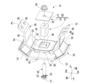
- FIG. 1 is a perspective view showing a vibration isolator as an embodiment of the present invention
- FIG. FIG. 2 is a front view showing the anti-vibration device shown in FIG. 1
- 2 is a top view of the anti-vibration device shown in FIG. 1
- FIG. FIG. 4 is a vertical cross-sectional view taken along line IV-IV of FIG. 3
- FIG. 2 is a front view showing a shaft member in the vibration isolator shown in FIG. 1
- FIG. 6 is a sectional view taken along line VI-VI of FIG. 5
- 2 is a cross-sectional view illustrating a state in which a vibrating body is mounted on the vibration isolator shown in FIG. 1
- FIG. 1. It is a perspective view explaining the main-body part preparation process which prepares the main-body part of the vibration isolator shown in FIG. 1. It is a perspective view explaining the stopper member arrangement
- the anti-vibration device 10 has a first mounting member 30 and a second mounting member 40 arranged to face each other, and both end portions of the first mounting member 30 and the second mounting member 40 form a pair of main rubber elastic bodies 20 , 20 . It has a structure elastically connected by
- the axial direction refers to the vertical direction in FIG. 2, which is the longitudinal direction of the second mounting member 40
- the front-rear direction is the vertical direction in FIG. 3, which is the width direction of the first and second mounting members 30, 40.
- the first mounting member 30 is formed by pressing a metal plate material such as iron or aluminum alloy, and has a longitudinal plate shape as a whole. 4, 8 and 9, the first mounting member 30 has a first flat plate portion 32 extending substantially horizontally at the center portion in the left-right direction, and a first fastening hole 34 is formed through the first flat plate portion 32. It is
- first inclined plate portions 33, 33 are integrally formed on both left and right sides of the first flat plate portion 32 of the first mounting member 30, respectively.
- the left and right end portions of the member 30 are configured.
- the first inclined plate portions 33 , 33 have a plate shape that gradually inclines upward as it goes outward to the left and right, and a pair of symmetrical plates are provided on the left and right sides of the first flat plate portion 32 .
- two fixing holes 36, 36 are formed in the first flat plate portion 32 of the first mounting member 30, and the first mounting member 30 is fixed to the vehicle body 80 side through the fixing holes 36, 36.
- the second mounting member 40 is made of a metal plate material such as iron or aluminum alloy, and has a laterally elongated plate shape as a whole.
- the second mounting member 40 has a second flat plate portion 42 extending substantially horizontally at the central portion in the longitudinal direction. is formed.
- the stopper hole 44 is rectangular in this embodiment, it may be circular or polygonal.
- a pair of second inclined plate portions 43, 43 are integrally formed on both sides of the second flat plate portion 42 in the length direction.
- the second inclined plate portions 43, 43 have a plate shape that is inclined upward in the thickness direction as it goes outward in the left-right direction.
- a pair of vertical wall portions 46, 46 protruding upward from the left and right outer end portions of the pair of second inclined plate portions 43, 43 are integrally provided.
- a pair of mounting pieces 47, 47 are integrally formed on the .
- the mounting piece 47 extends from the upper end of the vertical wall portion 46 at an angle to the left and right, and two bolt holes 48 and 49 extending in the thickness direction are formed at positions separated from each other in the front and rear direction.
- the pair of left and right mounting pieces 47 , 47 constitute both left and right end portions of the second mounting member 40 .
- the first mounting member 30 and the second mounting member 40 having such a structure are arranged such that the second mounting member 40 is arranged to face the first mounting member 30 upward, and the second flat plate portion 42 and the first flat plate portion 42 are arranged to face each other.
- the portion 32 is opposed to the vertical direction, and the first inclined plate portion 33 and the second inclined plate portion 43 are opposed to each other in an inclined direction with respect to the vertical direction.
- Main rubber elastic bodies 20, 20 are disposed between the facing surfaces of the left and right first inclined plate portions 33, 33 and the second inclined plate portions 43, 43, respectively.
- the two mounting members 40 are elastically connected by the pair of main rubber elastic bodies 20, 20 at both ends located on both sides of the first fastening hole 34 and the stopper hole 44. As shown in FIG.
- a rectangular stopper hole 44 penetrating vertically is formed in the central portion of the second flat plate portion 42 .
- Rubber layers 24, 25, and 26 acting as stoppers 22 acting in the vertical, horizontal, and longitudinal directions are provided on the inner peripheral surface of the stopper hole 44, and are integrated with the second mounting member 40 at the portion of the stopper hole 44. It is vulcanized.
- the rubber elastic body is vulcanized in the stopper hole 44 portion.
- the rubber elastic body may be formed by vulcanization.
- the shaft member 50 has a collar portion 51 arranged at one end in the vertical direction, extends vertically from the root of the collar portion 51, and extends circumferentially.
- a first protrusion 53 composed of a plurality of first protrusions 52 arranged at predetermined intervals in the direction, and a plurality of first protrusions 52 arranged at predetermined intervals in the circumferential direction.
- a second projecting portion 55 that extends in the vertical direction while being continuous with the configured first projecting portion 53 and that includes a plurality of second projecting portions 54 that are arranged at predetermined intervals in the circumferential direction. It has In this embodiment, the first protrusion 52 and the second protrusion 54 have the same shape.
- the first protrusion 52 and the second protrusion 54 are integrally formed as continuous protrusions extending in the axial direction indistinguishable from each other in appearance.
- the shape of the first protrusion 52 and the second protrusion 54 is a triangular shape with a tip pointed radially outward.
- the shape of the first protrusion 52 and the second protrusion 54 may be formed such that the distal ends thereof are formed in an arc shape or a gear shape (trapezoidal shape) facing radially outward.
- the shape of the first protrusion 52 and the second protrusion 54 is preferably a shape in which the width dimension in the circumferential direction gradually decreases toward the tip end side of the protrusion.
- the vertical stopper plate 70 has a rectangular flat plate shape, and has a through hole 72 extending vertically through which the shaft member 50 is inserted in the central portion. are doing.
- the stopper member 61 is composed of a rectangular parallelepiped, and has a second fastening hole 62 penetrating in the vertical direction, as shown in FIGS.
- the stopper member 61 has a rectangular parallelepiped shape, but may have a cylindrical shape or prismatic shape.
- FIG. 4 is a cross-sectional view of the anti-vibration device 10.
- the stopper 60 is composed of a stopper member 61 and a stopper plate 70 .
- the stopper member 61 is inserted through the stopper hole 44 .
- the stopper member 61 is inserted through the stopper hole 44 so that the lower end portion in the vertical direction is positioned against the first flat plate portion 32 of the first mounting member 30 so as to connect to the first fastening hole 34 located at the center portion of the first flat plate portion 32 . and the second fastening hole 62 penetrating vertically through the stopper member 61 are superimposed on each other.
- the lower end surface of the stopper member 61 is overlapped with the upper surface of the first flat plate portion 32 in a contact state.
- the first fastening hole 34 and the second fastening hole 62 are arranged on the same central axis.
- the entirety of the first fastening hole 34 overlaps with the second fastening hole 62, and the second fastening hole 62 spreads further to the outer peripheral side than the first fastening hole 34 on its entire circumference. It has an opening shape.
- the stopper member 61 With the stopper member 61 erected on the first flat plate portion 32 , the first fastening hole 34 located in the central portion of the first flat plate portion 32 constituting the first mounting member 30 and the second fastening hole formed in the stopper member 61 .
- the shaft member 50 is inserted and press-fitted into the fastening hole 62 from below the first mounting member 30 .
- the maximum diagonal (D) of the first projecting portion 53 and the second projecting portion 55 arranged on the shaft member 50 is larger than the diameter (D1) of the first fastening hole 34 and the diameter (D2) of the second fastening hole 62.
- the first projecting portion 53 and the second projecting portion 55 bite into the respective inner peripheral surfaces of the first fastening hole 34 and the second fastening hole 62 by being press-fitted.
- the first projecting portion 53 formed on the outer peripheral surface of the shaft member 50 and configured by a plurality of first projecting portions 52 arranged at predetermined intervals in the circumferential direction is the first flat plate portion.
- the inner peripheral surface of the first fastening hole 34 located in the central portion of 32 is abutted.
- Second protrusions 55 formed on the outer peripheral surface of the shaft member 50 and configured by a plurality of second protrusions arranged at predetermined intervals in the circumferential direction are formed on the inner peripheral surface of the stopper member 61.
- the stopper plate 70 is fixed to the upper end face of the stopper member 61 by screwing the shaft member 50 and the nut 58 together.
- FIG. 7 is a cross-sectional view of the vibration isolator shown in FIG. 1 with a vibrating body mounted thereon.
- the vibrating body 89 is mounted on the upper surfaces of a pair of left and right mounting pieces 47 , 47 arranged at both left and right end portions of the second mounting member 40 . It is formed in a pair of left and right mounting pieces 47, 47 and fixed by bolts (not shown) to two bolt holes 48, 49 penetrating in the thickness direction.
- the first projecting portion 53 and the second projecting portion 55 are formed on the outer peripheral surface of the shaft member 50, but are arranged at predetermined intervals in the circumferential direction.
- a first protrusion 53 is formed on the inner peripheral surface of the first fastening hole 34 and is brought into contact with the outer peripheral surface of the shaft member 50 .
- the second protrusion 55 extends vertically in a continuous state and is composed of a plurality of second protrusions 54 arranged at predetermined intervals in the circumferential direction on the inner periphery of the second fastening hole 62 It may be formed on a surface and brought into contact with the outer peripheral surface of the shaft member 50 .
- FIG. A first projecting portion 53 composed of a plurality of first projecting portions 52 arranged at predetermined intervals in the circumferential direction formed on the outer peripheral surface of the shaft member 50 is formed in the central portion of the first flat plate portion 32. It abuts on the inner peripheral surface of the first fastening hole 34 located there.
- the second mounting member 40 moves vertically, horizontally and longitudinally due to the vibration of the vibrating body 80 .
- the lateral movement causes the inner peripheral surface 62 of the stopper hole 44 formed in the second mounting member 40 to come into contact with the outer peripheral surface of the stopper member 61 of the second mounting member 40 .
- slippage occurs between the stopper member 61 and the first mounting member 30 . Since the shaft member 50, the first mounting member 30, and the stopper member 61 are integrated, the occurrence of slippage (movement) is suppressed.
- the stopper function is maintained, and excessive input to the rubber is reduced or prevented, thereby increasing the durability of the rubber elastic body.
- the first mounting member 51 formed on the outer peripheral surface of the shaft member 50 is in contact with the lower surface portion of the first mounting member 30 and the flange portion 51 formed on the shaft member 50 .
- a first protrusion 53 abuts on a first fastening hole 34 formed in the first mounting member 30
- a second protrusion 55 extending vertically continuously from the first protrusion 53 is a stopper member 61 . abuts on the second fastening hole 62 formed in the inner peripheral surface 62 of the .
- the shaft member 50 By press-fitting the shaft member 50 into the first fastening hole 34 and the second fastening hole 62, the first protrusion 53 and the second protrusion 55 are aligned with the first fastening hole 34 and the second fastening hole 62, respectively. It bites into the inner peripheral surface of the and comes into contact with it. Thereby, the flange portion 51 formed on the shaft member 50, the shaft member 50, the first mounting member 30, and the stopper member 61 are integrated and fixed. In particular, the shaft member 50 is fixed in a more stable state by being press-fitted on the flange portion 51 side and brought into contact with the lower surface of the first mounting member 30 while the flange portion 51 is in contact with the lower surface of the first mounting member 30 .
- the stopper member 61 slides (moves or moves) on the surface of the first mounting member 30 when the stopper load is applied.
- the occurrence of rattling) and the loosening of parts caused by such slippage are also suppressed.
- the function of restricting the amount of relative displacement between the first mounting member 30 and the second mounting member 40 by the stopper function is maintained, and the amount of excessive relative displacement between the first mounting member 30 and the second mounting member 40 is stabilized.
- excessive input to the rubber can be reduced or prevented, and the durability of the rubber elastic body can be enhanced.
- the shaft member 50, the stopper member 61 and the first mounting member 30 are made of metal material.
- the second projecting portions 55 arranged on the outer peripheral surface of the shaft member 50 at predetermined intervals in the circumferential direction are arranged on the stopper member 61.
- the second projecting portion 55 bites into the inner peripheral surface of the second fastening hole 62.
- the member 50 and the stopper member 61 are more strongly integrated. As a result, the occurrence of slippage (movement) and loosening of the parts are further suppressed, and the stopper function is maintained, thereby reducing or preventing excessive input to the rubber and increasing the durability of the rubber elastic body.
- the first projecting portions 52 arranged on the outer peripheral surface of the shaft member 30 at predetermined intervals in the circumferential direction are arranged at predetermined intervals. 1.
- the first projecting portion 52 abuts (is press-fitted into) the inner peripheral surface 41 of the first fastening hole 34 penetrating in the vertical direction arranged in the mounting member 30, the inner peripheral surface 41 of the first fastening hole 34
- the shaft member 50 and the stopper member 61 are more firmly integrated with each other. As a result, the occurrence of slippage (movement) and loosening of the parts are further suppressed, and the stopper function is maintained, thereby reducing or preventing excessive input to the rubber and increasing the durability of the rubber elastic body.
- the shaft member 50 of the present embodiment does not have the first protrusion 52 formed at the base end portion of the shaft portion on the collar portion 51 side.
- a recessed groove portion 56 extending in the circumferential direction is formed with an outer diameter smaller than that of the projecting portion 53 .
- the manufacturing method of the vibration isolator 10 includes a main body preparing step of preparing the main body 14 and a stopper member arranging step of arranging the outer peripheral surface of the stopper member 61 so as to face the inner peripheral surface 62 of the stopper hole 44. I have.
- the main body portion preparation process for preparing the main body portion 14 shown in FIG. This is the step of forming the main body portion 14 which is the main body of the vibration isolator 10 excluding the shaft member 50 , the stopper member 61 , the stopper plate 70 and the nut 58 .
- the first member 12 and the second mounting member 40, to which the fixing bolts 86 for fastening with the vehicle body 80 are attached, are placed in a predetermined mold (not shown). Then, an unvulcanized rubber material is injected between the first mounting member 30 and the second mounting member 40, and vulcanized into a rubber material by a conventionally used predetermined vulcanizing device (not shown). I do. In this way, the main rubber elastic bodies 20, 20 are formed between the first mounting member 30 and the second mounting member 40, and the main body 14 is formed.
- the stopper member arranging process shown in FIG. 9 will be described.
- the shaft member 50 is press-fitted into the first fastening hole 34 and the second fastening hole 62, and a plurality of projections arranged on the outer peripheral surface of the shaft member 50 are formed on the inner peripheral surface 41 of the first fastening hole 34 and the second fastening hole. This is the step of contacting the inner peripheral surface of 62 .
- the stopper member 61 is inserted through the stopper hole 44 formed in the central portion of the second mounting member 40 .
- the stopper With the second fastening hole 62 formed in the stopper member 61 and penetrating in the vertical direction and the first fastening hole 34 formed in the central portion of the first mounting member 30 and penetrating in the vertical direction overlapping each other, the stopper is mounted.
- a member 61 is erected on the first flat plate portion 32 of the first mounting member 30 .
- the shaft member 50 is press-fitted into the first fastening hole 34 and the second fastening hole 62 from below to above the first mounting member 30 .
- the first projecting portion 53 and the second projecting portion 55 bite into the inner peripheral surfaces of the first fastening hole 34 and the second fastening hole 62, respectively.
- a plurality of first projecting portions 53 and second projecting portions 55 are formed on the first mounting member 30 so as to be arranged at predetermined intervals in the circumferential direction on the outer peripheral surface of the shaft member 50 in the biting state. They abut on the first fastening hole 34 and the second fastening hole 62 formed in the stopper member 61, respectively, and are integrated and fixed. As a result, the occurrence of slippage (movement) between the first mounting member 30 and the stopper member 61 is suppressed. In addition, by suppressing loosening of the parts, the stopper function is maintained, and excessive input to the rubber is reduced or prevented, thereby increasing the durability of the rubber elastic body.
- the press-fit fixing portion of the shaft member 50 into the first fastening hole 34 of the first mounting member 30 and the second fastening hole 62 of the stopper member 61 has a plurality of ridges in the circumferential direction, Unlike in the case of a simple smooth cylindrical surface, there is no need for advanced dimensional control, excessive pressure force, and equipment to realize them, making it easy to realize and pressure force applied to the tip of multiple ridges. Alternatively, by concentrating the fixing force, it is possible to stably obtain the desired press-fitting fixing force.
- the protrusions are more reliably and efficiently engaged. It is possible to improve and stabilize the abutment and fixing state.
- the press-fit fixing area of the first projection 53 of the shaft member 50 coming into contact with the first fastening hole 34 of the first mounting member 30 is the thickness dimension of the first flat plate portion 32 (the axis of the first fastening hole 34 It is preferably 50% or more, more preferably 80% or more, and more preferably set substantially over the entire area as in the above embodiment.
- the press-fit fixing region of the second projection 55 of the shaft member 50 in contact with the second fastening hole 62 of the stopper member 61 is the first fastening hole 34 of the shaft member 50 in which the first projection 53 abuts. It is preferably 80% or more of the axial length dimension of the press-fit fixing region for the , more preferably the same or more axial length.
- the stopper member 61 does not need to have a straight cylindrical shape extending with a constant cross-sectional shape over the entire length.
- the base end portion (lower end portion) and the tip end portion (upper end portion) may have different cross-sectional shapes, and the tip end portion may be integrally formed with an outward flange-like portion to serve as a separate stopper. It is also possible to omit the plate.
- the outer peripheral surface of the stopper member 61 and the inner peripheral surface of the stopper hole 44 do not need to have similar shapes, and the distance between the opposing members (stopper gap dimension) at which the stopper function is achieved by abutting each other is different from that in the front-rear direction. They may be different in the left and right direction.
- the rubber layers 24, 25, and 26 that are vulcanized and adhered to the second mounting member 40 to form the stopper 22 may be vulcanized and adhered to the outer peripheral surface of the stopper member 61 as described above.
- a separate cylindrical stopper rubber can be attached to the stopper member 61 in an externally inserted state.
- Such a stopper rubber may also have different protrusion heights from the inner peripheral surface of the stopper hole 44 in the circumferential direction.
- the stopper hole 44 formed in the second mounting member 40 is not limited to the simple punched through hole shown in the example. Alternatively, by fixing a separate tubular body by welding or the like, it is possible to set the stopper abutment surface with which the stopper member 61 abuts to be large in the axial direction.
- first protrusion 52 and the second protrusion 54 formed at the contact portions between the shaft member 50 and the first fastening hole 34 and the second fastening hole 62 are not limited to the illustrated embodiment.
- the projections may be independent of each other, and the abutting portion between the shaft member 50 and the first fastening hole 34 and the abutting portion between the shaft member 50 and the second fastening hole 62 may be axially aligned with each other. It may be provided at a remote position.
- the diameter of the contact portion between the shaft member 50 and the first fastening hole 34 and the diameter size of the contact portion between the shaft member 50 and the second fastening hole 62 may be different from each other.
- the stopper member 61 since the stopper member 61 has a cylindrical shape that is elongated in the axial direction, it is possible to set the abutment portions between the shaft member 50 and the second fastening hole 62 at a plurality of locations that are different in the axial direction. be.
- the first and second protrusions forming contact portions between the shaft member 50 and the first fastening hole 34 or the second fastening hole 62 are also limited to the embodiments that extend continuously in the axial direction. Instead, it may be divided into a plurality of pieces in the axial direction, or may have a shape of a plurality of independent projections.
- the method for manufacturing a vibration isolator according to the present invention is not limitedly interpreted by the specific description of the above embodiment.
- the shaft member 50 is press-fitted into the first fastening hole 34 of the first mounting member 30 of the main body 14 from below and fixed. It may be in a planted state with respect to the first attachment member 30 .
- the separately prepared stopper member 61 is inserted into the stopper hole 44 of the second mounting member 40 of the main body 14 from above, and the shaft member 50 is press-fitted into the stopper hole 44 from below and fixed.
- the stopper member 61 may be fixed to the first mounting member 30 via the shaft member 50 .
Landscapes
- Engineering & Computer Science (AREA)
- General Engineering & Computer Science (AREA)
- Mechanical Engineering (AREA)
- Health & Medical Sciences (AREA)
- Child & Adolescent Psychology (AREA)
- Vibration Prevention Devices (AREA)
- Springs (AREA)
Priority Applications (2)
| Application Number | Priority Date | Filing Date | Title |
|---|---|---|---|
| EP23763195.7A EP4461989A4 (en) | 2022-03-04 | 2023-02-08 | VIBRATION DAMPING DEVICE AND METHOD FOR MANUFACTURING VIBRATION DAMPING DEVICE |
| JP2023539124A JP7373697B1 (ja) | 2022-03-04 | 2023-02-08 | 防振装置および防振装置の製造方法 |
Applications Claiming Priority (2)
| Application Number | Priority Date | Filing Date | Title |
|---|---|---|---|
| JP2022033085 | 2022-03-04 | ||
| JP2022-033085 | 2022-03-04 |
Publications (1)
| Publication Number | Publication Date |
|---|---|
| WO2023166933A1 true WO2023166933A1 (ja) | 2023-09-07 |
Family
ID=87883312
Family Applications (1)
| Application Number | Title | Priority Date | Filing Date |
|---|---|---|---|
| PCT/JP2023/004238 Ceased WO2023166933A1 (ja) | 2022-03-04 | 2023-02-08 | 防振装置および防振装置の製造方法 |
Country Status (3)
| Country | Link |
|---|---|
| EP (1) | EP4461989A4 (https=) |
| JP (1) | JP7373697B1 (https=) |
| WO (1) | WO2023166933A1 (https=) |
Citations (5)
| Publication number | Priority date | Publication date | Assignee | Title |
|---|---|---|---|---|
| JPS59127910U (ja) * | 1983-02-16 | 1984-08-28 | 本田技研工業株式会社 | 吊り棒等の取付装置 |
| JPH09151991A (ja) | 1995-11-28 | 1997-06-10 | Tokai Rubber Ind Ltd | 車両用防振支持装置 |
| JP2006144931A (ja) * | 2004-11-19 | 2006-06-08 | Tokai Rubber Ind Ltd | エンジンマウント |
| JP2015218754A (ja) * | 2014-05-14 | 2015-12-07 | 住友理工株式会社 | エンジンマウント |
| JP2018071768A (ja) * | 2016-11-04 | 2018-05-10 | 住友理工株式会社 | 防振装置 |
Family Cites Families (7)
| Publication number | Priority date | Publication date | Assignee | Title |
|---|---|---|---|---|
| US519411A (en) * | 1894-05-08 | William c | ||
| US5036727A (en) * | 1989-03-03 | 1991-08-06 | Saturn Corporation | Connecting bolt and assembly |
| FR2685404A1 (fr) * | 1991-12-20 | 1993-06-25 | Esswein Sa | Rivet crante pour assemblage de plaques. |
| JP4138750B2 (ja) * | 2002-11-29 | 2008-08-27 | 東洋ゴム工業株式会社 | 液封入式防振装置 |
| JP2008196517A (ja) * | 2007-02-08 | 2008-08-28 | Bridgestone Corp | カシメ構造、及び、それを有する防振装置 |
| KR20120075016A (ko) * | 2010-12-28 | 2012-07-06 | 주식회사 일진베어링 | 허브볼트 및 이를 구비한 휠 베어링 조립체 |
| JP6457876B2 (ja) * | 2015-04-16 | 2019-01-23 | 住友理工株式会社 | エンジンマウントとその製造方法 |
-
2023
- 2023-02-08 JP JP2023539124A patent/JP7373697B1/ja active Active
- 2023-02-08 EP EP23763195.7A patent/EP4461989A4/en active Pending
- 2023-02-08 WO PCT/JP2023/004238 patent/WO2023166933A1/ja not_active Ceased
Patent Citations (5)
| Publication number | Priority date | Publication date | Assignee | Title |
|---|---|---|---|---|
| JPS59127910U (ja) * | 1983-02-16 | 1984-08-28 | 本田技研工業株式会社 | 吊り棒等の取付装置 |
| JPH09151991A (ja) | 1995-11-28 | 1997-06-10 | Tokai Rubber Ind Ltd | 車両用防振支持装置 |
| JP2006144931A (ja) * | 2004-11-19 | 2006-06-08 | Tokai Rubber Ind Ltd | エンジンマウント |
| JP2015218754A (ja) * | 2014-05-14 | 2015-12-07 | 住友理工株式会社 | エンジンマウント |
| JP2018071768A (ja) * | 2016-11-04 | 2018-05-10 | 住友理工株式会社 | 防振装置 |
Non-Patent Citations (1)
| Title |
|---|
| See also references of EP4461989A4 |
Also Published As
| Publication number | Publication date |
|---|---|
| JPWO2023166933A1 (https=) | 2023-09-07 |
| EP4461989A1 (en) | 2024-11-13 |
| JP7373697B1 (ja) | 2023-11-02 |
| EP4461989A4 (en) | 2025-05-07 |
Similar Documents
| Publication | Publication Date | Title |
|---|---|---|
| US9476479B2 (en) | Tubular vibration-damping device used for vibration-damping connecting rod, vibration-damping connecting rod using the same, and method of manufacturing vibration-damping connecting rod | |
| JP5815364B2 (ja) | メンバマウント及びその組付構造 | |
| JP3841720B2 (ja) | ブラケット付き筒型マウント装置 | |
| US9523464B2 (en) | Cylindrical vibration-damping device equipped with outer bracket and outer bracket therefor | |
| JP6343535B2 (ja) | 筒型防振装置 | |
| CN104620012A (zh) | 防振装置 | |
| JP2006144972A (ja) | 防振ブッシュ組付構造 | |
| US10661648B2 (en) | Rubber stopper | |
| JP2008173990A (ja) | プロペラシャフトの支持構造 | |
| JP2018123859A (ja) | 締結部材付きの防振装置 | |
| WO2023166933A1 (ja) | 防振装置および防振装置の製造方法 | |
| US20130168907A1 (en) | Vibration isolator | |
| JP7602979B2 (ja) | 防振装置 | |
| JP2010054036A (ja) | モータ用防振マウント及びその製造方法 | |
| JPH10274268A (ja) | 防振ブッシュおよびブッシュ組立体 | |
| JP2009047207A (ja) | 防振装置 | |
| JP6635064B2 (ja) | エンジンマウントの仮止め構造 | |
| JP4724614B2 (ja) | 防振装置 | |
| WO2022202187A1 (ja) | 防振装置 | |
| JP2003269509A (ja) | 防振ブッシュ | |
| JP2008249032A (ja) | 防振装置 | |
| JP7561706B2 (ja) | 防振装置 | |
| JP2017067156A (ja) | 防振装置 | |
| JP2007263148A (ja) | メンバマウントおよびその製造方法 | |
| JP5230520B2 (ja) | 防振装置 |
Legal Events
| Date | Code | Title | Description |
|---|---|---|---|
| WWE | Wipo information: entry into national phase |
Ref document number: 2023539124 Country of ref document: JP |
|
| 121 | Ep: the epo has been informed by wipo that ep was designated in this application |
Ref document number: 23763195 Country of ref document: EP Kind code of ref document: A1 |
|
| WWE | Wipo information: entry into national phase |
Ref document number: 2401002214 Country of ref document: TH |
|
| WWE | Wipo information: entry into national phase |
Ref document number: 2023763195 Country of ref document: EP |
|
| ENP | Entry into the national phase |
Ref document number: 2023763195 Country of ref document: EP Effective date: 20240806 |
|
| NENP | Non-entry into the national phase |
Ref country code: DE |