WO2023166933A1 - Vibration damping device and manufacturing method for vibration damping device - Google Patents
Vibration damping device and manufacturing method for vibration damping device Download PDFInfo
- Publication number
- WO2023166933A1 WO2023166933A1 PCT/JP2023/004238 JP2023004238W WO2023166933A1 WO 2023166933 A1 WO2023166933 A1 WO 2023166933A1 JP 2023004238 W JP2023004238 W JP 2023004238W WO 2023166933 A1 WO2023166933 A1 WO 2023166933A1
- Authority
- WO
- WIPO (PCT)
- Prior art keywords
- fastening hole
- peripheral surface
- stopper
- shaft member
- ridges
- Prior art date
Links
- 238000013016 damping Methods 0.000 title claims abstract description 6
- 238000004519 manufacturing process Methods 0.000 title claims description 10
- 230000002093 peripheral effect Effects 0.000 claims description 120
- 230000000149 penetrating effect Effects 0.000 claims description 15
- 238000003780 insertion Methods 0.000 claims description 2
- 230000037431 insertion Effects 0.000 claims description 2
- 238000000034 method Methods 0.000 description 9
- 229910052751 metal Inorganic materials 0.000 description 7
- 239000002184 metal Substances 0.000 description 7
- 238000006073 displacement reaction Methods 0.000 description 5
- XEEYBQQBJWHFJM-UHFFFAOYSA-N Iron Chemical compound [Fe] XEEYBQQBJWHFJM-UHFFFAOYSA-N 0.000 description 4
- 239000000463 material Substances 0.000 description 4
- 229910000838 Al alloy Inorganic materials 0.000 description 2
- 229910000640 Fe alloy Inorganic materials 0.000 description 2
- 230000004323 axial length Effects 0.000 description 2
- 230000005540 biological transmission Effects 0.000 description 2
- 230000007423 decrease Effects 0.000 description 2
- 238000002360 preparation method Methods 0.000 description 2
- 239000012212 insulator Substances 0.000 description 1
- 230000013011 mating Effects 0.000 description 1
- 239000007769 metal material Substances 0.000 description 1
- 238000012986 modification Methods 0.000 description 1
- 230000004048 modification Effects 0.000 description 1
- 238000003825 pressing Methods 0.000 description 1
- 230000002265 prevention Effects 0.000 description 1
- 230000001105 regulatory effect Effects 0.000 description 1
- 238000004073 vulcanization Methods 0.000 description 1
- 238000003466 welding Methods 0.000 description 1
Images


Classifications
-
- F—MECHANICAL ENGINEERING; LIGHTING; HEATING; WEAPONS; BLASTING
- F16—ENGINEERING ELEMENTS AND UNITS; GENERAL MEASURES FOR PRODUCING AND MAINTAINING EFFECTIVE FUNCTIONING OF MACHINES OR INSTALLATIONS; THERMAL INSULATION IN GENERAL
- F16F—SPRINGS; SHOCK-ABSORBERS; MEANS FOR DAMPING VIBRATION
- F16F15/00—Suppression of vibrations in systems; Means or arrangements for avoiding or reducing out-of-balance forces, e.g. due to motion
- F16F15/02—Suppression of vibrations of non-rotating, e.g. reciprocating systems; Suppression of vibrations of rotating systems by use of members not moving with the rotating systems
- F16F15/04—Suppression of vibrations of non-rotating, e.g. reciprocating systems; Suppression of vibrations of rotating systems by use of members not moving with the rotating systems using elastic means
- F16F15/08—Suppression of vibrations of non-rotating, e.g. reciprocating systems; Suppression of vibrations of rotating systems by use of members not moving with the rotating systems using elastic means with rubber springs ; with springs made of rubber and metal
Definitions
- the present invention relates to an anti-vibration device and a method for manufacturing an anti-vibration device.
- a support rubber elastic body (insulator) is attached to a vehicle body frame such as a cross member so as to support a power unit such as an engine and a transmission (transmission), and attenuates vibrations from the power unit so that they are not transmitted to the vehicle body;
- a vibration isolator having a stopper for suppressing excessive displacement of a supporting rubber elastic body is known.
- Patent Document 1 discloses a plate-shaped first support bracket and a second support bracket as a type of anti-vibration support device for a vehicle, and the first support bracket and the second support bracket.
- the rubber layer of the first support fitting repeatedly collides with the connecting fitting due to the displacement of the first support fitting in the longitudinal and vertical directions of the vehicle. Slippage occurs between metal fittings and connecting metal fittings, loosening occurs in the screwing of bolts and nuts, parts fall off, and the loosening (rattling) and falling off of the parts cause constant longitudinal and vertical displacement of the vehicle. There is a risk that the function of regulating it will not work and the durability will decrease.
- the present invention has a simpler structure, suppresses the occurrence of slippage and loosening of parts, maintains the stopper function, and reduces or prevents excessive input to the rubber, thereby improving the durability of the rubber elastic body.
- the object of the present invention is to provide an anti-vibration device capable of increasing the vibration resistance and a method for manufacturing the same.
- a vibration isolator includes a plate-like first mounting member having a first fastening hole penetrating in the axial direction; A plate-shaped member spaced apart in the axial direction penetrates in the axial direction, overlaps the first fastening hole in projection in the axial direction, and has a diameter larger than the diameter of the first fastening hole.
- a second mounting member having a stopper hole having a large hole diameter; a pair of rubber elastic bodies connecting opposite surfaces of both end sides of the first mounting member and both end sides of the second mounting member; a cylindrical member having a second fastening hole extending therethrough, the stopper member being inserted into the stopper hole and having an outer peripheral surface facing an inner peripheral surface of the stopper hole; a shaft member that is inserted through the hole and the second fastening hole and fastens the stopper member to the first mounting member, the outer peripheral surface of the shaft member and the inner peripheral surface of the first fastening hole A plurality of first ridges are formed on either one of the ridges and arranged at predetermined intervals in the circumferential direction.
- the shaft member is in contact with the other of the outer peripheral surface of the shaft member and the inner peripheral surface of the first fastening hole, and the outer peripheral surface of the shaft member and the A plurality of second ridges are formed on either one of the inner peripheral surfaces of the second fastening hole and are arranged at predetermined intervals in the circumferential direction, and the shaft member is connected to the second fastening hole.
- the plurality of second protrusions are in contact with the other of the outer peripheral surface of the shaft member and the inner peripheral surface of the second fastening hole.
- a plurality of first ridges arranged at predetermined intervals in the circumferential direction are formed on either one of the outer peripheral surface of the shaft member and the inner peripheral surface of the first fastening hole. is formed and the shaft member is inserted through the first fastening hole, the plurality of first ridges contact the other of the inner peripheral surface of the first fastening hole and the outer peripheral surface of the shaft member. It is considered to be in a state of contact.
- a plurality of second ridges arranged at predetermined intervals in the circumferential direction are formed on either one of the outer peripheral surface of the shaft member and the inner peripheral surface of the second fastening hole, and , in a state in which the shaft member is inserted through the second fastening hole, the plurality of second ridges are in contact with the other of the inner peripheral surface of the second fastening hole and the outer peripheral surface of the shaft member. ing. Therefore, by suppressing the occurrence of slippage and suppressing loosening of parts, the stopper function is maintained, and excessive input to the rubber is reduced or prevented, thereby increasing the durability of the rubber elastic body.
- a second aspect is the vibration isolator according to the first aspect, wherein each of the plurality of first ridges and the plurality of second ridges are located on the outer peripheral surface of the shaft member or on the first fastening hole. and the inner peripheral surface of each of the second fastening holes, the plurality of first ridges are formed to extend in the axial direction, and the plurality of second ridges are formed to: It is formed so as to extend in the axial direction while being continuous with the plurality of first ridges.
- the plurality of first protrusions are formed to extend in the axial direction, and the plurality of second protrusions extend in the axial direction while being continuous with the plurality of first protrusions. Since it is formed so as to extend, the outer peripheral surface of the shaft member and the inner peripheral surface of the first fastening hole are fixed by the first protrusion, and the second protrusion connected to the first protrusion fixes the The outer peripheral surface of the shaft member and the inner peripheral surface of the second fastening hole are fixed.
- a third aspect is the vibration damping device according to the first or second aspect, wherein the shaft member has a flange portion arranged at one end in the axial direction, and the plurality of first ridges It is formed from the base of the collar portion on the outer peripheral surface of the shaft member.
- the flange portion since the plurality of first projections are formed from the base of the flange portion arranged at one end in the axial direction of the shaft member, the flange portion penetrates in the axial direction. It abuts on a plate-shaped first mounting member having a hole. Therefore, the outer peripheral surface of the shaft member, the inner peripheral surface of the first fastening hole, and the flange portion come into contact with each other at the portion where the slippage occurs, and are integrated and fixed. By increasing the contact distance between the first projection and the inner peripheral surface of the first fastening hole, the occurrence of slippage is suppressed, and the stopper function is maintained to reduce or prevent excessive input to the rubber. The durability of the rubber elastic body can be enhanced.
- a fourth aspect is the vibration isolator according to any one of the first to third aspects, wherein the plurality of second ridges are formed on the outer peripheral surface of the shaft member, and the shaft member is and a hardness greater than that of the stopper member, and an outer diameter including the plurality of second ridges is greater than a hole diameter of the second tightening hole.
- the second protrusion formed on the outer peripheral surface of the shaft member is the second fastening formed on the stopper member.
- the hole is dug (press-fitted) and firmly fixed.
- the outer diameter including the plurality of second protrusions formed on the outer peripheral surface of the shaft member is larger than the second fastening hole, the second protrusions formed on the outer peripheral surface of the shaft member bites into (is press-fitted into) the inner peripheral surface of the second fastening hole formed in the stopper member, and is firmly fixed. Therefore, the occurrence of slipping is suppressed and the looseness of the parts is suppressed, so that the stopper function is maintained, and excessive input to the rubber is reduced or prevented, thereby increasing the durability of the rubber elastic body.
- a fifth aspect is the vibration isolator according to any one of the first to fourth aspects, wherein the plurality of first ridges are formed on the outer peripheral surface of the shaft member, and the shaft member is and a hardness greater than that of the first mounting member, and an outer diameter including the plurality of first ridges is greater than a diameter of the first fastening hole.
- the first protrusion formed on the outer peripheral surface of the shaft member is formed on the first mounting member. It bites (press-fits) into the first fastening hole, and is firmly fixed. Furthermore, since the outer diameter including the plurality of first protrusions formed on the outer peripheral surface of the shaft member is larger than the first fastening hole, the first protrusions formed on the outer peripheral surface of the shaft member , bite (press fit) into the inner peripheral surface of the first fastening hole formed in the first mounting member, and are firmly fixed. Therefore, the occurrence of slipping is suppressed and the looseness of the parts is suppressed, so that the stopper function is maintained, and excessive input to the rubber is reduced or prevented, thereby increasing the durability of the rubber elastic body.
- a method for manufacturing a vibration isolator includes: a plate-like first mounting member having a first fastening hole penetrating in the axial direction; A plate-like member arranged in a squat shape, and has a stopper hole which penetrates in the axial direction, overlaps with the first fastening hole when projected in the axial direction, and has a hole diameter larger than that of the first fastening hole.
- a main body preparing step of preparing a main body including: 2 mounting members; and a pair of rubber elastic bodies on opposing surfaces of both end sides of the first mounting member and both end sides of the second mounting member, respectively; A plurality of ridges extending in the axial direction are formed on the outer peripheral surface at predetermined intervals in a state in which a cylindrical stopper member having a second fastening hole penetrating in the direction is inserted into the stopper hole.
- the shaft member is press-fitted into the first fastening hole and the second fastening hole, and the plurality of ridges are brought into contact with the inner peripheral surface of the first fastening hole and the inner peripheral surface of the second fastening hole.
- the shaft member having a plurality of projections extending in the axial direction is formed in the first fastening hole formed in the first mounting member and the cylindrical stopper member.
- the first mounting member and the stopper are press-fitted into the second fastening hole, and the plurality of protrusions are brought into contact with and bite into the inner peripheral surface of the first fastening hole and the inner peripheral surface of the second fastening hole.
- the member can be fixed.
- the first mounting member and the stopper member are integrated, the occurrence of slippage and the loosening of the parts are suppressed, and the stopper function is maintained, thereby reducing or preventing excessive input to the rubber, thereby reducing rubber elasticity. Increases body endurance.
- a first mounting member having a first fastening hole in the central portion and a second mounting member having a stopper hole in the central portion are arranged to face each other.
- the plurality of first protrusions and the plurality of second protrusions are brought into contact with the mating member, thereby suppressing the occurrence of slippage and suppressing the loosening of the parts, thereby achieving the stopper function.
- the durability of the rubber elastic body is increased by reducing or preventing excessive input to the rubber.
- the shaft member having a plurality of ridges extending in the axial direction at predetermined intervals on the outer peripheral surface is provided with the first fastening hole and the second fastening hole.
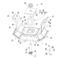
- FIG. 1 is a perspective view showing a vibration isolator as an embodiment of the present invention
- FIG. FIG. 2 is a front view showing the anti-vibration device shown in FIG. 1
- 2 is a top view of the anti-vibration device shown in FIG. 1
- FIG. FIG. 4 is a vertical cross-sectional view taken along line IV-IV of FIG. 3
- FIG. 2 is a front view showing a shaft member in the vibration isolator shown in FIG. 1
- FIG. 6 is a sectional view taken along line VI-VI of FIG. 5
- 2 is a cross-sectional view illustrating a state in which a vibrating body is mounted on the vibration isolator shown in FIG. 1
- FIG. 1. It is a perspective view explaining the main-body part preparation process which prepares the main-body part of the vibration isolator shown in FIG. 1. It is a perspective view explaining the stopper member arrangement
- the anti-vibration device 10 has a first mounting member 30 and a second mounting member 40 arranged to face each other, and both end portions of the first mounting member 30 and the second mounting member 40 form a pair of main rubber elastic bodies 20 , 20 . It has a structure elastically connected by
- the axial direction refers to the vertical direction in FIG. 2, which is the longitudinal direction of the second mounting member 40
- the front-rear direction is the vertical direction in FIG. 3, which is the width direction of the first and second mounting members 30, 40.
- the first mounting member 30 is formed by pressing a metal plate material such as iron or aluminum alloy, and has a longitudinal plate shape as a whole. 4, 8 and 9, the first mounting member 30 has a first flat plate portion 32 extending substantially horizontally at the center portion in the left-right direction, and a first fastening hole 34 is formed through the first flat plate portion 32. It is
- first inclined plate portions 33, 33 are integrally formed on both left and right sides of the first flat plate portion 32 of the first mounting member 30, respectively.
- the left and right end portions of the member 30 are configured.
- the first inclined plate portions 33 , 33 have a plate shape that gradually inclines upward as it goes outward to the left and right, and a pair of symmetrical plates are provided on the left and right sides of the first flat plate portion 32 .
- two fixing holes 36, 36 are formed in the first flat plate portion 32 of the first mounting member 30, and the first mounting member 30 is fixed to the vehicle body 80 side through the fixing holes 36, 36.
- the second mounting member 40 is made of a metal plate material such as iron or aluminum alloy, and has a laterally elongated plate shape as a whole.
- the second mounting member 40 has a second flat plate portion 42 extending substantially horizontally at the central portion in the longitudinal direction. is formed.
- the stopper hole 44 is rectangular in this embodiment, it may be circular or polygonal.
- a pair of second inclined plate portions 43, 43 are integrally formed on both sides of the second flat plate portion 42 in the length direction.
- the second inclined plate portions 43, 43 have a plate shape that is inclined upward in the thickness direction as it goes outward in the left-right direction.
- a pair of vertical wall portions 46, 46 protruding upward from the left and right outer end portions of the pair of second inclined plate portions 43, 43 are integrally provided.
- a pair of mounting pieces 47, 47 are integrally formed on the .
- the mounting piece 47 extends from the upper end of the vertical wall portion 46 at an angle to the left and right, and two bolt holes 48 and 49 extending in the thickness direction are formed at positions separated from each other in the front and rear direction.
- the pair of left and right mounting pieces 47 , 47 constitute both left and right end portions of the second mounting member 40 .
- the first mounting member 30 and the second mounting member 40 having such a structure are arranged such that the second mounting member 40 is arranged to face the first mounting member 30 upward, and the second flat plate portion 42 and the first flat plate portion 42 are arranged to face each other.
- the portion 32 is opposed to the vertical direction, and the first inclined plate portion 33 and the second inclined plate portion 43 are opposed to each other in an inclined direction with respect to the vertical direction.
- Main rubber elastic bodies 20, 20 are disposed between the facing surfaces of the left and right first inclined plate portions 33, 33 and the second inclined plate portions 43, 43, respectively.
- the two mounting members 40 are elastically connected by the pair of main rubber elastic bodies 20, 20 at both ends located on both sides of the first fastening hole 34 and the stopper hole 44. As shown in FIG.
- a rectangular stopper hole 44 penetrating vertically is formed in the central portion of the second flat plate portion 42 .
- Rubber layers 24, 25, and 26 acting as stoppers 22 acting in the vertical, horizontal, and longitudinal directions are provided on the inner peripheral surface of the stopper hole 44, and are integrated with the second mounting member 40 at the portion of the stopper hole 44. It is vulcanized.
- the rubber elastic body is vulcanized in the stopper hole 44 portion.
- the rubber elastic body may be formed by vulcanization.
- the shaft member 50 has a collar portion 51 arranged at one end in the vertical direction, extends vertically from the root of the collar portion 51, and extends circumferentially.
- a first protrusion 53 composed of a plurality of first protrusions 52 arranged at predetermined intervals in the direction, and a plurality of first protrusions 52 arranged at predetermined intervals in the circumferential direction.
- a second projecting portion 55 that extends in the vertical direction while being continuous with the configured first projecting portion 53 and that includes a plurality of second projecting portions 54 that are arranged at predetermined intervals in the circumferential direction. It has In this embodiment, the first protrusion 52 and the second protrusion 54 have the same shape.
- the first protrusion 52 and the second protrusion 54 are integrally formed as continuous protrusions extending in the axial direction indistinguishable from each other in appearance.
- the shape of the first protrusion 52 and the second protrusion 54 is a triangular shape with a tip pointed radially outward.
- the shape of the first protrusion 52 and the second protrusion 54 may be formed such that the distal ends thereof are formed in an arc shape or a gear shape (trapezoidal shape) facing radially outward.
- the shape of the first protrusion 52 and the second protrusion 54 is preferably a shape in which the width dimension in the circumferential direction gradually decreases toward the tip end side of the protrusion.
- the vertical stopper plate 70 has a rectangular flat plate shape, and has a through hole 72 extending vertically through which the shaft member 50 is inserted in the central portion. are doing.
- the stopper member 61 is composed of a rectangular parallelepiped, and has a second fastening hole 62 penetrating in the vertical direction, as shown in FIGS.
- the stopper member 61 has a rectangular parallelepiped shape, but may have a cylindrical shape or prismatic shape.
- FIG. 4 is a cross-sectional view of the anti-vibration device 10.
- the stopper 60 is composed of a stopper member 61 and a stopper plate 70 .
- the stopper member 61 is inserted through the stopper hole 44 .
- the stopper member 61 is inserted through the stopper hole 44 so that the lower end portion in the vertical direction is positioned against the first flat plate portion 32 of the first mounting member 30 so as to connect to the first fastening hole 34 located at the center portion of the first flat plate portion 32 . and the second fastening hole 62 penetrating vertically through the stopper member 61 are superimposed on each other.
- the lower end surface of the stopper member 61 is overlapped with the upper surface of the first flat plate portion 32 in a contact state.
- the first fastening hole 34 and the second fastening hole 62 are arranged on the same central axis.
- the entirety of the first fastening hole 34 overlaps with the second fastening hole 62, and the second fastening hole 62 spreads further to the outer peripheral side than the first fastening hole 34 on its entire circumference. It has an opening shape.
- the stopper member 61 With the stopper member 61 erected on the first flat plate portion 32 , the first fastening hole 34 located in the central portion of the first flat plate portion 32 constituting the first mounting member 30 and the second fastening hole formed in the stopper member 61 .
- the shaft member 50 is inserted and press-fitted into the fastening hole 62 from below the first mounting member 30 .
- the maximum diagonal (D) of the first projecting portion 53 and the second projecting portion 55 arranged on the shaft member 50 is larger than the diameter (D1) of the first fastening hole 34 and the diameter (D2) of the second fastening hole 62.
- the first projecting portion 53 and the second projecting portion 55 bite into the respective inner peripheral surfaces of the first fastening hole 34 and the second fastening hole 62 by being press-fitted.
- the first projecting portion 53 formed on the outer peripheral surface of the shaft member 50 and configured by a plurality of first projecting portions 52 arranged at predetermined intervals in the circumferential direction is the first flat plate portion.
- the inner peripheral surface of the first fastening hole 34 located in the central portion of 32 is abutted.
- Second protrusions 55 formed on the outer peripheral surface of the shaft member 50 and configured by a plurality of second protrusions arranged at predetermined intervals in the circumferential direction are formed on the inner peripheral surface of the stopper member 61.
- the stopper plate 70 is fixed to the upper end face of the stopper member 61 by screwing the shaft member 50 and the nut 58 together.
- FIG. 7 is a cross-sectional view of the vibration isolator shown in FIG. 1 with a vibrating body mounted thereon.
- the vibrating body 89 is mounted on the upper surfaces of a pair of left and right mounting pieces 47 , 47 arranged at both left and right end portions of the second mounting member 40 . It is formed in a pair of left and right mounting pieces 47, 47 and fixed by bolts (not shown) to two bolt holes 48, 49 penetrating in the thickness direction.
- the first projecting portion 53 and the second projecting portion 55 are formed on the outer peripheral surface of the shaft member 50, but are arranged at predetermined intervals in the circumferential direction.
- a first protrusion 53 is formed on the inner peripheral surface of the first fastening hole 34 and is brought into contact with the outer peripheral surface of the shaft member 50 .
- the second protrusion 55 extends vertically in a continuous state and is composed of a plurality of second protrusions 54 arranged at predetermined intervals in the circumferential direction on the inner periphery of the second fastening hole 62 It may be formed on a surface and brought into contact with the outer peripheral surface of the shaft member 50 .
- FIG. A first projecting portion 53 composed of a plurality of first projecting portions 52 arranged at predetermined intervals in the circumferential direction formed on the outer peripheral surface of the shaft member 50 is formed in the central portion of the first flat plate portion 32. It abuts on the inner peripheral surface of the first fastening hole 34 located there.
- the second mounting member 40 moves vertically, horizontally and longitudinally due to the vibration of the vibrating body 80 .
- the lateral movement causes the inner peripheral surface 62 of the stopper hole 44 formed in the second mounting member 40 to come into contact with the outer peripheral surface of the stopper member 61 of the second mounting member 40 .
- slippage occurs between the stopper member 61 and the first mounting member 30 . Since the shaft member 50, the first mounting member 30, and the stopper member 61 are integrated, the occurrence of slippage (movement) is suppressed.
- the stopper function is maintained, and excessive input to the rubber is reduced or prevented, thereby increasing the durability of the rubber elastic body.
- the first mounting member 51 formed on the outer peripheral surface of the shaft member 50 is in contact with the lower surface portion of the first mounting member 30 and the flange portion 51 formed on the shaft member 50 .
- a first protrusion 53 abuts on a first fastening hole 34 formed in the first mounting member 30
- a second protrusion 55 extending vertically continuously from the first protrusion 53 is a stopper member 61 . abuts on the second fastening hole 62 formed in the inner peripheral surface 62 of the .
- the shaft member 50 By press-fitting the shaft member 50 into the first fastening hole 34 and the second fastening hole 62, the first protrusion 53 and the second protrusion 55 are aligned with the first fastening hole 34 and the second fastening hole 62, respectively. It bites into the inner peripheral surface of the and comes into contact with it. Thereby, the flange portion 51 formed on the shaft member 50, the shaft member 50, the first mounting member 30, and the stopper member 61 are integrated and fixed. In particular, the shaft member 50 is fixed in a more stable state by being press-fitted on the flange portion 51 side and brought into contact with the lower surface of the first mounting member 30 while the flange portion 51 is in contact with the lower surface of the first mounting member 30 .
- the stopper member 61 slides (moves or moves) on the surface of the first mounting member 30 when the stopper load is applied.
- the occurrence of rattling) and the loosening of parts caused by such slippage are also suppressed.
- the function of restricting the amount of relative displacement between the first mounting member 30 and the second mounting member 40 by the stopper function is maintained, and the amount of excessive relative displacement between the first mounting member 30 and the second mounting member 40 is stabilized.
- excessive input to the rubber can be reduced or prevented, and the durability of the rubber elastic body can be enhanced.
- the shaft member 50, the stopper member 61 and the first mounting member 30 are made of metal material.
- the second projecting portions 55 arranged on the outer peripheral surface of the shaft member 50 at predetermined intervals in the circumferential direction are arranged on the stopper member 61.
- the second projecting portion 55 bites into the inner peripheral surface of the second fastening hole 62.
- the member 50 and the stopper member 61 are more strongly integrated. As a result, the occurrence of slippage (movement) and loosening of the parts are further suppressed, and the stopper function is maintained, thereby reducing or preventing excessive input to the rubber and increasing the durability of the rubber elastic body.
- the first projecting portions 52 arranged on the outer peripheral surface of the shaft member 30 at predetermined intervals in the circumferential direction are arranged at predetermined intervals. 1.
- the first projecting portion 52 abuts (is press-fitted into) the inner peripheral surface 41 of the first fastening hole 34 penetrating in the vertical direction arranged in the mounting member 30, the inner peripheral surface 41 of the first fastening hole 34
- the shaft member 50 and the stopper member 61 are more firmly integrated with each other. As a result, the occurrence of slippage (movement) and loosening of the parts are further suppressed, and the stopper function is maintained, thereby reducing or preventing excessive input to the rubber and increasing the durability of the rubber elastic body.
- the shaft member 50 of the present embodiment does not have the first protrusion 52 formed at the base end portion of the shaft portion on the collar portion 51 side.
- a recessed groove portion 56 extending in the circumferential direction is formed with an outer diameter smaller than that of the projecting portion 53 .
- the manufacturing method of the vibration isolator 10 includes a main body preparing step of preparing the main body 14 and a stopper member arranging step of arranging the outer peripheral surface of the stopper member 61 so as to face the inner peripheral surface 62 of the stopper hole 44. I have.
- the main body portion preparation process for preparing the main body portion 14 shown in FIG. This is the step of forming the main body portion 14 which is the main body of the vibration isolator 10 excluding the shaft member 50 , the stopper member 61 , the stopper plate 70 and the nut 58 .
- the first member 12 and the second mounting member 40, to which the fixing bolts 86 for fastening with the vehicle body 80 are attached, are placed in a predetermined mold (not shown). Then, an unvulcanized rubber material is injected between the first mounting member 30 and the second mounting member 40, and vulcanized into a rubber material by a conventionally used predetermined vulcanizing device (not shown). I do. In this way, the main rubber elastic bodies 20, 20 are formed between the first mounting member 30 and the second mounting member 40, and the main body 14 is formed.
- the stopper member arranging process shown in FIG. 9 will be described.
- the shaft member 50 is press-fitted into the first fastening hole 34 and the second fastening hole 62, and a plurality of projections arranged on the outer peripheral surface of the shaft member 50 are formed on the inner peripheral surface 41 of the first fastening hole 34 and the second fastening hole. This is the step of contacting the inner peripheral surface of 62 .
- the stopper member 61 is inserted through the stopper hole 44 formed in the central portion of the second mounting member 40 .
- the stopper With the second fastening hole 62 formed in the stopper member 61 and penetrating in the vertical direction and the first fastening hole 34 formed in the central portion of the first mounting member 30 and penetrating in the vertical direction overlapping each other, the stopper is mounted.
- a member 61 is erected on the first flat plate portion 32 of the first mounting member 30 .
- the shaft member 50 is press-fitted into the first fastening hole 34 and the second fastening hole 62 from below to above the first mounting member 30 .
- the first projecting portion 53 and the second projecting portion 55 bite into the inner peripheral surfaces of the first fastening hole 34 and the second fastening hole 62, respectively.
- a plurality of first projecting portions 53 and second projecting portions 55 are formed on the first mounting member 30 so as to be arranged at predetermined intervals in the circumferential direction on the outer peripheral surface of the shaft member 50 in the biting state. They abut on the first fastening hole 34 and the second fastening hole 62 formed in the stopper member 61, respectively, and are integrated and fixed. As a result, the occurrence of slippage (movement) between the first mounting member 30 and the stopper member 61 is suppressed. In addition, by suppressing loosening of the parts, the stopper function is maintained, and excessive input to the rubber is reduced or prevented, thereby increasing the durability of the rubber elastic body.
- the press-fit fixing portion of the shaft member 50 into the first fastening hole 34 of the first mounting member 30 and the second fastening hole 62 of the stopper member 61 has a plurality of ridges in the circumferential direction, Unlike in the case of a simple smooth cylindrical surface, there is no need for advanced dimensional control, excessive pressure force, and equipment to realize them, making it easy to realize and pressure force applied to the tip of multiple ridges. Alternatively, by concentrating the fixing force, it is possible to stably obtain the desired press-fitting fixing force.
- the protrusions are more reliably and efficiently engaged. It is possible to improve and stabilize the abutment and fixing state.
- the press-fit fixing area of the first projection 53 of the shaft member 50 coming into contact with the first fastening hole 34 of the first mounting member 30 is the thickness dimension of the first flat plate portion 32 (the axis of the first fastening hole 34 It is preferably 50% or more, more preferably 80% or more, and more preferably set substantially over the entire area as in the above embodiment.
- the press-fit fixing region of the second projection 55 of the shaft member 50 in contact with the second fastening hole 62 of the stopper member 61 is the first fastening hole 34 of the shaft member 50 in which the first projection 53 abuts. It is preferably 80% or more of the axial length dimension of the press-fit fixing region for the , more preferably the same or more axial length.
- the stopper member 61 does not need to have a straight cylindrical shape extending with a constant cross-sectional shape over the entire length.
- the base end portion (lower end portion) and the tip end portion (upper end portion) may have different cross-sectional shapes, and the tip end portion may be integrally formed with an outward flange-like portion to serve as a separate stopper. It is also possible to omit the plate.
- the outer peripheral surface of the stopper member 61 and the inner peripheral surface of the stopper hole 44 do not need to have similar shapes, and the distance between the opposing members (stopper gap dimension) at which the stopper function is achieved by abutting each other is different from that in the front-rear direction. They may be different in the left and right direction.
- the rubber layers 24, 25, and 26 that are vulcanized and adhered to the second mounting member 40 to form the stopper 22 may be vulcanized and adhered to the outer peripheral surface of the stopper member 61 as described above.
- a separate cylindrical stopper rubber can be attached to the stopper member 61 in an externally inserted state.
- Such a stopper rubber may also have different protrusion heights from the inner peripheral surface of the stopper hole 44 in the circumferential direction.
- the stopper hole 44 formed in the second mounting member 40 is not limited to the simple punched through hole shown in the example. Alternatively, by fixing a separate tubular body by welding or the like, it is possible to set the stopper abutment surface with which the stopper member 61 abuts to be large in the axial direction.
- first protrusion 52 and the second protrusion 54 formed at the contact portions between the shaft member 50 and the first fastening hole 34 and the second fastening hole 62 are not limited to the illustrated embodiment.
- the projections may be independent of each other, and the abutting portion between the shaft member 50 and the first fastening hole 34 and the abutting portion between the shaft member 50 and the second fastening hole 62 may be axially aligned with each other. It may be provided at a remote position.
- the diameter of the contact portion between the shaft member 50 and the first fastening hole 34 and the diameter size of the contact portion between the shaft member 50 and the second fastening hole 62 may be different from each other.
- the stopper member 61 since the stopper member 61 has a cylindrical shape that is elongated in the axial direction, it is possible to set the abutment portions between the shaft member 50 and the second fastening hole 62 at a plurality of locations that are different in the axial direction. be.
- the first and second protrusions forming contact portions between the shaft member 50 and the first fastening hole 34 or the second fastening hole 62 are also limited to the embodiments that extend continuously in the axial direction. Instead, it may be divided into a plurality of pieces in the axial direction, or may have a shape of a plurality of independent projections.
- the method for manufacturing a vibration isolator according to the present invention is not limitedly interpreted by the specific description of the above embodiment.
- the shaft member 50 is press-fitted into the first fastening hole 34 of the first mounting member 30 of the main body 14 from below and fixed. It may be in a planted state with respect to the first attachment member 30 .
- the separately prepared stopper member 61 is inserted into the stopper hole 44 of the second mounting member 40 of the main body 14 from above, and the shaft member 50 is press-fitted into the stopper hole 44 from below and fixed.
- the stopper member 61 may be fixed to the first mounting member 30 via the shaft member 50 .
Abstract
The present invention provides a vibration damping device that can inhibit component loosening and inhibit the occurrence of slipping with an even simpler configuration. This vibration damping device comprises: a plate-shaped first attachment member 30 that has a first fastening hole 34; a plate-shaped second attachment member 40 that has a stopper hole 44; a pair of rubber elastic bodies 20, 20 that connect the first attachment member 30 and the second attachment member 40 between facing surfaces on both end sides of said members; a stopper member 61 that has a second fastening hole 62; and a shaft member 50 that fastens the stopper member 61 to the first attachment member 30. A plurality of protrusions 52, 54 disposed at prescribed intervals in the circumferential direction are provided to a press-fit fixing section of the shaft member 50 and the first fastening hole 34 and second fastening hole 62. The shaft member 50 is fixed to the first attachment member 30 and the stopper member 61 by bringing the protrusions 52, 54 into contact with said members.
Description
本発明は、防振装置および防振装置の製造方法に関するものである。
The present invention relates to an anti-vibration device and a method for manufacturing an anti-vibration device.
従来から、エンジンやトランスミッション(変速機)等のパワーユニットを支持するようにクロスメンバ等の車体フレームに取り付けられ、パワーユニットからの振動を車体に伝えないように減衰させる支持ゴム弾性体(インシュレータ)と、支持ゴム弾性体の過度の変位を抑制するストッパーを備えた防振装置が知られている。
Conventionally, a support rubber elastic body (insulator) is attached to a vehicle body frame such as a cross member so as to support a power unit such as an engine and a transmission (transmission), and attenuates vibrations from the power unit so that they are not transmitted to the vehicle body; A vibration isolator having a stopper for suppressing excessive displacement of a supporting rubber elastic body is known.
例えば特開平9-151991号公報(特許文献1)には、車両用防振支持装置の一種として板状の第1支持金具及び第2支持金具と、それら第1支持金具及び第2支持金具にて上下に挟まれる状態に一体に加硫接着されたブロック状の一対のマウント本体ゴムと、円環状のフランジ部と、連結金具と、円環状フランジ部と連結金具と第2支持金具とをボルトとナットで連結するようになっている。
For example, Japanese Patent Application Laid-Open No. 9-151991 (Patent Document 1) discloses a plate-shaped first support bracket and a second support bracket as a type of anti-vibration support device for a vehicle, and the first support bracket and the second support bracket. A pair of block-shaped mount main body rubber vulcanized and bonded together in a state of being vertically sandwiched by bolts, an annular flange portion, a connecting metal fitting, an annular flange portion, a connecting metal fitting, and a second support metal fitting. and is connected with a nut.
ところで、特許文献1の車両用防振支持装置においては、第1支持金具が車両の前後,上下方向の変位により、第1支持金具のゴム層が連結金具に繰り返し衝突することで、第1支持金具と連結金具との間で滑りが発生し、ボルトとナットの螺合に緩みが発生し、部品の脱落や、その部品の緩み(ガタツキ)・脱落による車両の前後、上下方向の変位を一定に規制する機能が働かずに耐久性が低下する恐れがある。
By the way, in the anti-vibration support device for a vehicle disclosed in Patent Document 1, the rubber layer of the first support fitting repeatedly collides with the connecting fitting due to the displacement of the first support fitting in the longitudinal and vertical directions of the vehicle. Slippage occurs between metal fittings and connecting metal fittings, loosening occurs in the screwing of bolts and nuts, parts fall off, and the loosening (rattling) and falling off of the parts cause constant longitudinal and vertical displacement of the vehicle. There is a risk that the function of regulating it will not work and the durability will decrease.
そこで、本発明は、より簡単な構成で、滑りの発生および部品の緩みが抑制されることで、ストッパー機能が維持され、ゴムへの過剰な入力を低減又は防止により、ゴム弾性体の耐久性を高められる防振装置とその製造方法を提供することを目的としたものである。
Therefore, the present invention has a simpler structure, suppresses the occurrence of slippage and loosening of parts, maintains the stopper function, and reduces or prevents excessive input to the rubber, thereby improving the durability of the rubber elastic body. The object of the present invention is to provide an anti-vibration device capable of increasing the vibration resistance and a method for manufacturing the same.
上記目的を達成するために、本発明の第一の態様に係る防振装置は、軸方向に貫通する第1締結孔を有する板状の第1取付部材と、前記第1取付部材に対して前記軸方向に離間して配置される板状の部材であって、前記軸方向に貫通し、前記軸方向の投影において前記第1締結孔と重なり、かつ、前記第1締結孔の孔径よりも大きい孔径を有するストッパー孔を有する第2取付部材と、前記第1取付部材の両端側と前記第2取付部材の両端側との対向面をそれぞれ連結する一対のゴム弾性体と、前記軸方向に貫通する第2締結孔を有する筒状の部材であって、前記ストッパー孔に挿入され、かつ、外周面が前記ストッパー孔の内周面と対向して配置されるストッパー部材と、前記第1締結孔と前記第2締結孔とに挿通され、前記ストッパー部材を前記第1取付部材に締結する軸部材と、を備え、前記軸部材の外周面、及び、前記第1締結孔の内周面のいずれか一方には、周方向に所定の間隔をおいて配置される複数の第1突条が形成されており、かつ、前記軸部材が前記第1締結孔に挿通された状態において、前記複数の第1突条が、前記軸部材の外周面、及び、前記第1締結孔の内周面のいずれか他方に当接された状態とされており、前記軸部材の外周面、及び、前記第2締結孔の内周面のいずれか一方には、周方向に所定の間隔をおいて配置される複数の第2突条が形成されており、かつ、前記軸部材が前記第2締結孔に挿通された状態において、前記複数の第2突条が、前記軸部材の外周面、及び、前記第2締結孔の内周面のいずれか他方に当接された状態とされている。
In order to achieve the above object, a vibration isolator according to a first aspect of the present invention includes a plate-like first mounting member having a first fastening hole penetrating in the axial direction; A plate-shaped member spaced apart in the axial direction penetrates in the axial direction, overlaps the first fastening hole in projection in the axial direction, and has a diameter larger than the diameter of the first fastening hole. a second mounting member having a stopper hole having a large hole diameter; a pair of rubber elastic bodies connecting opposite surfaces of both end sides of the first mounting member and both end sides of the second mounting member; a cylindrical member having a second fastening hole extending therethrough, the stopper member being inserted into the stopper hole and having an outer peripheral surface facing an inner peripheral surface of the stopper hole; a shaft member that is inserted through the hole and the second fastening hole and fastens the stopper member to the first mounting member, the outer peripheral surface of the shaft member and the inner peripheral surface of the first fastening hole A plurality of first ridges are formed on either one of the ridges and arranged at predetermined intervals in the circumferential direction. is in contact with the other of the outer peripheral surface of the shaft member and the inner peripheral surface of the first fastening hole, and the outer peripheral surface of the shaft member and the A plurality of second ridges are formed on either one of the inner peripheral surfaces of the second fastening hole and are arranged at predetermined intervals in the circumferential direction, and the shaft member is connected to the second fastening hole. , the plurality of second protrusions are in contact with the other of the outer peripheral surface of the shaft member and the inner peripheral surface of the second fastening hole.
第一の態様によれば、軸部材の外周面、及び、第1締結孔の内周面のいずれか一方には、周方向に所定の間隔をおいて配置される複数の第1突条が形成されており、かつ、軸部材が第1締結孔に挿通された状態において、複数の第1突条が、第1締結孔の内周面、及び軸部材の外周面のいずれか他方に当接された状態とされている。また、軸部材の外周面、及び、第2締結孔の内周面のいずれか一方には、周方向に所定の間隔をおいて配置される複数の第2突条が形成されており、かつ、軸部材が第2締結孔に挿通された状態において、複数の第2突条が、第2締結孔の内周面、及び軸部材の外周面のいずれか他方に当接された状態とされている。それゆえ、滑りの発生を抑制し、部品の緩みを抑制することで、ストッパー機能が維持されることでゴムへの過剰な入力を低減又は防止することでゴム弾性体の耐久性を高められる。
According to the first aspect, a plurality of first ridges arranged at predetermined intervals in the circumferential direction are formed on either one of the outer peripheral surface of the shaft member and the inner peripheral surface of the first fastening hole. is formed and the shaft member is inserted through the first fastening hole, the plurality of first ridges contact the other of the inner peripheral surface of the first fastening hole and the outer peripheral surface of the shaft member. It is considered to be in a state of contact. Further, a plurality of second ridges arranged at predetermined intervals in the circumferential direction are formed on either one of the outer peripheral surface of the shaft member and the inner peripheral surface of the second fastening hole, and , in a state in which the shaft member is inserted through the second fastening hole, the plurality of second ridges are in contact with the other of the inner peripheral surface of the second fastening hole and the outer peripheral surface of the shaft member. ing. Therefore, by suppressing the occurrence of slippage and suppressing loosening of parts, the stopper function is maintained, and excessive input to the rubber is reduced or prevented, thereby increasing the durability of the rubber elastic body.
第二の態様は、第一の態様に記載の防振装置において、各複数の前記第1突条と前記第2突条が、共に、前記軸部材の外周面、又は、前記第1締結孔と前記第2締結孔の各内周面に形成されていると共に、前記複数の第1突条は、前記軸方向に延在するように形成されており、前記複数の第2突条は、前記複数の第1突条に連続した状態で前記軸方向に延在するように形成されているものである。
A second aspect is the vibration isolator according to the first aspect, wherein each of the plurality of first ridges and the plurality of second ridges are located on the outer peripheral surface of the shaft member or on the first fastening hole. and the inner peripheral surface of each of the second fastening holes, the plurality of first ridges are formed to extend in the axial direction, and the plurality of second ridges are formed to: It is formed so as to extend in the axial direction while being continuous with the plurality of first ridges.
第二の態様によれば、複数の第1突状が、軸方向に延在するように形成されて、複数の第2突状が、複数の第1突状に連続した状態で軸方向に延在するように形成されていることから、第1突状部により軸部材の外周面と第1締結孔の内周面とが固定され、第1突状部に連続した第2突状により軸部材の外周面と第2締結孔の内周面とが固定される。それゆえ、軸部材の外周面,第1締結孔の内周面および第2締結孔の内周面が、一体化し固定されることで、滑りの発生および部品の緩みが抑制されることで、ストッパー機能が維持され、ゴムへの過剰な入力を低減又は防止することでゴム弾性体の耐久性を高められる。
According to the second aspect, the plurality of first protrusions are formed to extend in the axial direction, and the plurality of second protrusions extend in the axial direction while being continuous with the plurality of first protrusions. Since it is formed so as to extend, the outer peripheral surface of the shaft member and the inner peripheral surface of the first fastening hole are fixed by the first protrusion, and the second protrusion connected to the first protrusion fixes the The outer peripheral surface of the shaft member and the inner peripheral surface of the second fastening hole are fixed. Therefore, by integrating and fixing the outer peripheral surface of the shaft member, the inner peripheral surface of the first fastening hole, and the inner peripheral surface of the second fastening hole, occurrence of slippage and loosening of parts are suppressed, By maintaining the stopper function and reducing or preventing excessive input to the rubber, the durability of the rubber elastic body can be enhanced.
第三の態様は、第一又は二の態様に記載の防振装置において、前記軸部材は、前記軸方向の一端に配置される鍔部を有し、前記複数の第1突条は、前記軸部材の外周面における前記鍔部の付根から形成されている。
A third aspect is the vibration damping device according to the first or second aspect, wherein the shaft member has a flange portion arranged at one end in the axial direction, and the plurality of first ridges It is formed from the base of the collar portion on the outer peripheral surface of the shaft member.
第三の態様によれば、複数の第1突状が、軸部材の軸方向の一端に配置される鍔部の付根から形成されていることから、鍔部が軸方向に貫通する第1締結孔を有する板状の第1取付部材と当接する。それゆえ、滑りの発生する部分において、軸部材の外周面,第1締結孔の内周面および鍔部が当接状態となり、一体化し固定され、さらに付け根から形成されることで、複数の第1突状と第1締結孔の内周面の当接距離が長くなることにより、滑りの発生が抑制され、ストッパー機能が維持されることでゴムへの過剰な入力を低減又は防止することでゴム弾性体の耐久性を高められる。
According to the third aspect, since the plurality of first projections are formed from the base of the flange portion arranged at one end in the axial direction of the shaft member, the flange portion penetrates in the axial direction. It abuts on a plate-shaped first mounting member having a hole. Therefore, the outer peripheral surface of the shaft member, the inner peripheral surface of the first fastening hole, and the flange portion come into contact with each other at the portion where the slippage occurs, and are integrated and fixed. By increasing the contact distance between the first projection and the inner peripheral surface of the first fastening hole, the occurrence of slippage is suppressed, and the stopper function is maintained to reduce or prevent excessive input to the rubber. The durability of the rubber elastic body can be enhanced.
第四の態様は、第一~第三の何れか1つの態様に記載の防振装置において、前記複数の第2突条は、前記軸部材の外周面に形成されており、前記軸部材は、前記ストッパー部材の硬度よりも大きい硬度を有し、かつ、前記複数の第2突条を含む外径が、前記第2締孔の孔径よりも大きくされている。
A fourth aspect is the vibration isolator according to any one of the first to third aspects, wherein the plurality of second ridges are formed on the outer peripheral surface of the shaft member, and the shaft member is and a hardness greater than that of the stopper member, and an outer diameter including the plurality of second ridges is greater than a hole diameter of the second tightening hole.
第四の態様によれば、軸部材の硬度がストッパー部材の硬度よりも大きくされていることから、軸部材の外周面に形成される第2突状が、ストッパー部材に形成される第2締結孔にくい込み(圧入され)、強固に固定される。さらに、軸部材の外周面に形成される複数の第2突状を含む外径が、第2締結孔よりも大きくされていることから、軸部材の外周面に形成される第2突状部が、ストッパー部材に形成される第2締結孔の内周面に食い込み(圧入され)、強固に固定される。それゆえ、滑りの発生が抑制され、部品の緩みが抑制されことで、ストッパー機能が維持されることでゴムへの過剰な入力を低減又は防止することでゴム弾性体の耐久性を高められる。
According to the fourth aspect, since the hardness of the shaft member is greater than the hardness of the stopper member, the second protrusion formed on the outer peripheral surface of the shaft member is the second fastening formed on the stopper member. The hole is dug (press-fitted) and firmly fixed. Furthermore, since the outer diameter including the plurality of second protrusions formed on the outer peripheral surface of the shaft member is larger than the second fastening hole, the second protrusions formed on the outer peripheral surface of the shaft member bites into (is press-fitted into) the inner peripheral surface of the second fastening hole formed in the stopper member, and is firmly fixed. Therefore, the occurrence of slipping is suppressed and the looseness of the parts is suppressed, so that the stopper function is maintained, and excessive input to the rubber is reduced or prevented, thereby increasing the durability of the rubber elastic body.
第五の態様は、第一~第四の何れか1つの態様に記載の防振装置において、前記複数の第1突条は、前記軸部材の外周面に形成されており、前記軸部材は、前記第1取付部材の硬度よりも大きい硬度を有し、かつ、前記複数の第1突条を含む外径が、前記第1締結孔の孔径よりも大きくされている。
A fifth aspect is the vibration isolator according to any one of the first to fourth aspects, wherein the plurality of first ridges are formed on the outer peripheral surface of the shaft member, and the shaft member is and a hardness greater than that of the first mounting member, and an outer diameter including the plurality of first ridges is greater than a diameter of the first fastening hole.
第五の態様によれば、軸部材の硬度が第1取付部材の硬度よりも大きくされていることから、軸部材の外周面に形成される第1突状が、第1取付部材に形成される第1締結孔に食い込み(圧入)、強固に固定される。さらに、軸部材の外周面に形成される複数の第1突状を含む外径が、第1締結孔よりも大きくされていることから、軸部材の外周面に形成される第1突状が、第1取付部材に形成される第1締結孔の内周面に食い込み(圧入)、強固に固定される。それゆえ、滑りの発生が抑制され、部品の緩みが抑制されことで、ストッパー機能が維持されることでゴムへの過剰な入力を低減又は防止することでゴム弾性体の耐久性を高められる。
According to the fifth aspect, since the hardness of the shaft member is set higher than that of the first mounting member, the first protrusion formed on the outer peripheral surface of the shaft member is formed on the first mounting member. It bites (press-fits) into the first fastening hole, and is firmly fixed. Furthermore, since the outer diameter including the plurality of first protrusions formed on the outer peripheral surface of the shaft member is larger than the first fastening hole, the first protrusions formed on the outer peripheral surface of the shaft member , bite (press fit) into the inner peripheral surface of the first fastening hole formed in the first mounting member, and are firmly fixed. Therefore, the occurrence of slipping is suppressed and the looseness of the parts is suppressed, so that the stopper function is maintained, and excessive input to the rubber is reduced or prevented, thereby increasing the durability of the rubber elastic body.
本発明の第六の態様に係る防振装置の製造方法は、軸方向に貫通する第1締結孔を有する板状の第1取付部材と、前記第1取付部材に対して前記軸方向に離間して配置される板状部材であって、前記軸方向に貫通し、前記軸方向の投影において前記第1締結孔と重なり、かつ、前記第1締結孔よりも孔径が大きいストッパー孔を有する第2取付部材と、前記第1取付部材の両端側と前記第2取付部材の両端側との対向面がそれぞれ一対のゴム弾性体と、を備える本体部を準備する本体部準備工程と、前記軸方向に貫通する第2締結孔を有する筒状のストッパー部材を、前記ストッパー孔に挿入させた状態で、外周面に所定の間隔をおいて前記軸方向に延在する複数の突条が形成された軸部材を、前記第1締結孔と前記第2締結孔とに圧入して、前記複数の突条を前記第1締結孔の内周面と前記第2締結孔の内周面とに当接させると共に、前記ストッパー部材の外周面を前記ストッパー孔の内周面に対向するように配置させるストッパー部材配置工程と、を含む。
A method for manufacturing a vibration isolator according to a sixth aspect of the present invention includes: a plate-like first mounting member having a first fastening hole penetrating in the axial direction; A plate-like member arranged in a squat shape, and has a stopper hole which penetrates in the axial direction, overlaps with the first fastening hole when projected in the axial direction, and has a hole diameter larger than that of the first fastening hole. a main body preparing step of preparing a main body including: 2 mounting members; and a pair of rubber elastic bodies on opposing surfaces of both end sides of the first mounting member and both end sides of the second mounting member, respectively; A plurality of ridges extending in the axial direction are formed on the outer peripheral surface at predetermined intervals in a state in which a cylindrical stopper member having a second fastening hole penetrating in the direction is inserted into the stopper hole. The shaft member is press-fitted into the first fastening hole and the second fastening hole, and the plurality of ridges are brought into contact with the inner peripheral surface of the first fastening hole and the inner peripheral surface of the second fastening hole. a stopper member arranging step of placing the outer peripheral surface of the stopper member in contact with the inner peripheral surface of the stopper hole and arranging the outer peripheral surface of the stopper member so as to face the inner peripheral surface of the stopper hole.
本発明の第六の態様によれば、軸方向に延在する複数に突状が形成された軸部材を、第1取付部材に形成される第1締結孔と筒状のストッパー部材に形成される第2締結孔に圧入し、複数の突条を前記第1締結孔の内周面と前記第2締結孔の内周面とに当接させ、食い込ませることで、第1取付部材とストッパー部材を固定することができる。これにより、第1取付部材とストッパー部材とが一体化され、滑りの発生および部品の緩みが抑制され、ストッパー機能が維持されることでゴムへの過剰な入力を低減又は防止することでゴム弾性体の耐久性を高められる。
According to the sixth aspect of the present invention, the shaft member having a plurality of projections extending in the axial direction is formed in the first fastening hole formed in the first mounting member and the cylindrical stopper member. The first mounting member and the stopper are press-fitted into the second fastening hole, and the plurality of protrusions are brought into contact with and bite into the inner peripheral surface of the first fastening hole and the inner peripheral surface of the second fastening hole. The member can be fixed. As a result, the first mounting member and the stopper member are integrated, the occurrence of slippage and the loosening of the parts are suppressed, and the stopper function is maintained, thereby reducing or preventing excessive input to the rubber, thereby reducing rubber elasticity. Increases body endurance.
本発明の第七の態様に係る防振装置の製造方法は、中央部分に第1締結孔を有する第1取付部材と中央部分にストッパー孔を有する第2取付部材とが対向配置されて両側部分において一対のゴム弾性体で連結された本体部を準備する工程と、軸方向に貫通する第2締結孔を有しており、下端面が前記第1取付部材の中央部分の上面への重ね合わせ面とされると共に、上端部分が前記第2取付部材のストッパー孔へ隙間をもって挿通される挿通部とされるストッパー部材を準備する工程と、周方向に所定の間隔をおいて軸方向に延びる複数の突条が外周面に形成されており、前記第1取付部材の前記第1締結孔と前記ストッパー部材の前記第2締結孔とに挿通される軸部材を準備する工程と、該軸部材を前記第1取付部材の前記第1締結孔へ圧入して前記複数の突条を該第1締結孔の内周面に当接させて固定する工程と、該軸部材を前記ストッパー部材の前記第2締結孔へ圧入して前記複数の突状を該第2締結孔の内周面に当接させて固定する工程とを、含む。
In a method for manufacturing a vibration isolator according to a seventh aspect of the present invention, a first mounting member having a first fastening hole in the central portion and a second mounting member having a stopper hole in the central portion are arranged to face each other. a step of preparing a body portion connected by a pair of rubber elastic bodies in step 3, and a second fastening hole penetrating in the axial direction, the lower end surface of which is superimposed on the upper surface of the central portion of the first mounting member a step of preparing a stopper member which serves as a surface and whose upper end portion serves as an insertion portion which is inserted into the stopper hole of the second mounting member with a gap; are formed on the outer peripheral surface, and preparing a shaft member that is inserted into the first fastening hole of the first mounting member and the second fastening hole of the stopper member; a step of press-fitting the plurality of ridges into the first fastening hole of the first mounting member to abut and fix the plurality of ridges to the inner peripheral surface of the first fastening hole; and a step of press-fitting into the second fastening hole and fixing the plurality of projections by contacting the inner peripheral surface of the second fastening hole.
本発明の防振装置は、複数の第1突状および複数の第2突状を相手部材に当接することにより、滑りの発生が抑制され、部品の緩みが抑制されることで、ストッパー機能が維持され、ゴムへの過剰な入力を低減又は防止することでゴム弾性体の耐久性を高められる。
In the anti-vibration device of the present invention, the plurality of first protrusions and the plurality of second protrusions are brought into contact with the mating member, thereby suppressing the occurrence of slippage and suppressing the loosening of the parts, thereby achieving the stopper function. The durability of the rubber elastic body is increased by reducing or preventing excessive input to the rubber.
本発明の防振装置の製造方法によれば、外周面に所定の間隔をおいて軸方向に延在する複数の突条が形成された軸部材を、第1締結孔と第2締結孔とに圧入して、複数の突条を第1締結孔の内周面と第2締結孔の内周面とに当接させることにより、滑りの発生が抑制され、ストッパー機能が維持されることでゴムへの過剰な入力を低減又は防止によりゴム弾性体の耐久性を高められる。
According to the method for manufacturing the vibration isolator of the present invention, the shaft member having a plurality of ridges extending in the axial direction at predetermined intervals on the outer peripheral surface is provided with the first fastening hole and the second fastening hole. By press-fitting and bringing a plurality of ridges into contact with the inner peripheral surface of the first fastening hole and the inner peripheral surface of the second fastening hole, the occurrence of slippage is suppressed and the stopper function is maintained. By reducing or preventing excessive input to the rubber, the durability of the rubber elastic body can be enhanced.
以下、本発明の実施の形態を図面に基づいて説明する。まず、本発明の対象となる防振装置の構造について説明する。
Hereinafter, embodiments of the present invention will be described based on the drawings. First, the structure of the anti-vibration device to which the present invention is applied will be described.
図1,図2,図3,図4および図7には、本発明の第一の実施形態としての防振装置10が示されている。防振装置10は、第1取付部材30と第2取付部材40が相互に対向配置されて、それら第1取付部材30と第2取付部材40の両端部分が一対の本体ゴム弾性体20,20によって弾性連結された構造を有している。なお、以下の説明において、特に説明がない限り、軸方向とは第1取付部材30と第2取付部材40の対向方向である図2中の上下方向を、左右方向とは第1取付部材30および第2取付部材40の長手方向である図2中の左右方向を、前後方向とは第1,第2の取付部材30,40の幅方向である図3中の上下方向を、それぞれ言う。
1, 2, 3, 4 and 7 show a vibration isolator 10 as a first embodiment of the present invention. The anti-vibration device 10 has a first mounting member 30 and a second mounting member 40 arranged to face each other, and both end portions of the first mounting member 30 and the second mounting member 40 form a pair of main rubber elastic bodies 20 , 20 . It has a structure elastically connected by In the following description, unless otherwise specified, the axial direction refers to the vertical direction in FIG. 2, which is the longitudinal direction of the second mounting member 40, and the front-rear direction is the vertical direction in FIG. 3, which is the width direction of the first and second mounting members 30, 40.
第1取付部材30は、鉄やアルミニウム合金などの金属板材をプレス加工して形成されており、全体として長手板形状を有している。また、図4、図8および図9第1取付部材30は、左右方向の中央部分が略水平に広がる第1平板部32とされて、第1平板部32に第1締結孔34が貫通形成されている。
The first mounting member 30 is formed by pressing a metal plate material such as iron or aluminum alloy, and has a longitudinal plate shape as a whole. 4, 8 and 9, the first mounting member 30 has a first flat plate portion 32 extending substantially horizontally at the center portion in the left-right direction, and a first fastening hole 34 is formed through the first flat plate portion 32. It is
さらに、第1取付部材30における第1平板部32の左右両側には、第1傾斜板部33,33がそれぞれ一体形成されており、それら左右の第1傾斜板部33,33によって第1取付部材30の左右両端部分が構成されている。第1傾斜板部33,33は、左右外方に行くに従って次第に上傾する板形状とされており、左右対称の一対が第1平板部32の左右に設けられている。
Further, first inclined plate portions 33, 33 are integrally formed on both left and right sides of the first flat plate portion 32 of the first mounting member 30, respectively. The left and right end portions of the member 30 are configured. The first inclined plate portions 33 , 33 have a plate shape that gradually inclines upward as it goes outward to the left and right, and a pair of symmetrical plates are provided on the left and right sides of the first flat plate portion 32 .
また、第1取付部材30には2つの固定孔36,36が第1平板部32に形成されており、固定孔36,36において第1取付部材30が車体80側に固定される。
In addition, two fixing holes 36, 36 are formed in the first flat plate portion 32 of the first mounting member 30, and the first mounting member 30 is fixed to the vehicle body 80 side through the fixing holes 36, 36.
第2取付部材40は、第1取付部材30と同様に、鉄やアルミニウム合金などの金属板材で形成されており、全体として左右に長手板形状を有している。また、第2取付部材40は、長さ方向の中央部分が略水平に広がる第2平板部42とされており、第2平板部42の中央部分には、上下に貫通する矩形のストッパー孔44が形成されている。本実施形態では、ストッパー孔44が矩形とされているが、円形や多角形でも良い。
Like the first mounting member 30, the second mounting member 40 is made of a metal plate material such as iron or aluminum alloy, and has a laterally elongated plate shape as a whole. The second mounting member 40 has a second flat plate portion 42 extending substantially horizontally at the central portion in the longitudinal direction. is formed. Although the stopper hole 44 is rectangular in this embodiment, it may be circular or polygonal.
さらに、第2平板部42の長さ方向両側には、一対の第2傾斜板部43,43が一体形成されている。第2傾斜板部43,43は、左右方向外側に行くに従って厚さ方向で上傾する板状とされている。
Furthermore, a pair of second inclined plate portions 43, 43 are integrally formed on both sides of the second flat plate portion 42 in the length direction. The second inclined plate portions 43, 43 have a plate shape that is inclined upward in the thickness direction as it goes outward in the left-right direction.
また、一対の第2傾斜板部43,43の左右外端部から上方に突出する一対の縦壁部46,46を一体で備え、さらに、一対の縦壁部46,46の左右方向外方には、一対の取付片47,47が一体形成されている。取付片47は、縦壁部46の上端から左右外方に傾斜して延び出しており、厚さ方向に貫通する二つのボルト孔48,49が前後で相互に離隔した位置に貫通形成されており、左右一対の取付片47,47によって第2取付部材40の左右方向両端部分が構成されている。
A pair of vertical wall portions 46, 46 protruding upward from the left and right outer end portions of the pair of second inclined plate portions 43, 43 are integrally provided. A pair of mounting pieces 47, 47 are integrally formed on the . The mounting piece 47 extends from the upper end of the vertical wall portion 46 at an angle to the left and right, and two bolt holes 48 and 49 extending in the thickness direction are formed at positions separated from each other in the front and rear direction. The pair of left and right mounting pieces 47 , 47 constitute both left and right end portions of the second mounting member 40 .
このような構造とされた第1取付部材30と第2取付部材40は、第2取付部材40が第1取付部材30に対して上方に対向配置されて、第2平板部42と第1平板部32が上下方向に対向せしめられると共に、第1傾斜板部33と第2傾斜板部43が上下方向に対して傾斜した向きで互いに対向せしめられる。そして、左右の第1傾斜板部33,33と、第2傾斜板部43,43の各対向面間にそれぞれ本体ゴム弾性体20,20が配設されており、第1取付部材30と第2取付部材40が、第1締結孔34及びストッパー孔44を挟んで両側位置する両端側において、それら一対の本体ゴム弾性体20,20によって弾性連結されている。
The first mounting member 30 and the second mounting member 40 having such a structure are arranged such that the second mounting member 40 is arranged to face the first mounting member 30 upward, and the second flat plate portion 42 and the first flat plate portion 42 are arranged to face each other. The portion 32 is opposed to the vertical direction, and the first inclined plate portion 33 and the second inclined plate portion 43 are opposed to each other in an inclined direction with respect to the vertical direction. Main rubber elastic bodies 20, 20 are disposed between the facing surfaces of the left and right first inclined plate portions 33, 33 and the second inclined plate portions 43, 43, respectively. The two mounting members 40 are elastically connected by the pair of main rubber elastic bodies 20, 20 at both ends located on both sides of the first fastening hole 34 and the stopper hole 44. As shown in FIG.
図4,図8及び図9に示しているように、上下方向に貫通する矩形のストッパー孔44は、第2平板部42の中央部分に形成されている。上下方向,左右方向および前後方向に作用するストッパー22となるゴム層24,25,26が、ストッパー孔44の内周面に設けられており、ストッパー孔44の部分において第2取付部材40に一体加硫成形されている。本実施形態では、ストッパー孔44の部分にゴム弾性体を加硫形成されているが、ストッパー孔44の部分にゴム弾性体を形成しないで、ストッパー孔44の中に配置されるストッパー部材61にゴム弾性体を加硫形成しても良い。
As shown in FIGS. 4, 8 and 9, a rectangular stopper hole 44 penetrating vertically is formed in the central portion of the second flat plate portion 42 . Rubber layers 24, 25, and 26 acting as stoppers 22 acting in the vertical, horizontal, and longitudinal directions are provided on the inner peripheral surface of the stopper hole 44, and are integrated with the second mounting member 40 at the portion of the stopper hole 44. It is vulcanized. In this embodiment, the rubber elastic body is vulcanized in the stopper hole 44 portion. The rubber elastic body may be formed by vulcanization.
軸部材50は、図4,図5,図6および図7に示すように、上下方向の一端に配置される鍔部51を有し、鍔部51の付根から上下方向に延在し、周方向に所定の間隔をおいて配置される複数の第1突状52から構成される第1突状部53と、周方向に所定の間隔をおいて配置される複数の第1突状52から構成される第1突状部53に連続した状態で上下方向に延在し、周方向に所定の間隔をおいて配置される複数の第2突状54から構成される第2突状部55を備えている。本実施形態では、第1突状52と第2突状54とは同一形状とされている。即ち、本実施形態では、第1突状52と第2突状54が、外観上では区別できずに一体的に連続して軸方向に延びる連続突状によって構成されている。なお、本実施形態では、第1突状52及び第2突状54の形状が、径方向外側に向かい先端が尖った三角形状とされている。尤も、第1突状52及び第2突状54の形状は、径方向外側に向かい先端が円弧形状や歯車形状(台形状)などで形成されていても良い。なお、第1突状52及び第2突状54の形状は、突出先端側に向かって周方向の幅寸法が次第に小さくなる形状が好適である。
As shown in FIGS. 4, 5, 6 and 7, the shaft member 50 has a collar portion 51 arranged at one end in the vertical direction, extends vertically from the root of the collar portion 51, and extends circumferentially. A first protrusion 53 composed of a plurality of first protrusions 52 arranged at predetermined intervals in the direction, and a plurality of first protrusions 52 arranged at predetermined intervals in the circumferential direction. A second projecting portion 55 that extends in the vertical direction while being continuous with the configured first projecting portion 53 and that includes a plurality of second projecting portions 54 that are arranged at predetermined intervals in the circumferential direction. It has In this embodiment, the first protrusion 52 and the second protrusion 54 have the same shape. That is, in the present embodiment, the first protrusion 52 and the second protrusion 54 are integrally formed as continuous protrusions extending in the axial direction indistinguishable from each other in appearance. In the present embodiment, the shape of the first protrusion 52 and the second protrusion 54 is a triangular shape with a tip pointed radially outward. Of course, the shape of the first protrusion 52 and the second protrusion 54 may be formed such that the distal ends thereof are formed in an arc shape or a gear shape (trapezoidal shape) facing radially outward. It should be noted that the shape of the first protrusion 52 and the second protrusion 54 is preferably a shape in which the width dimension in the circumferential direction gradually decreases toward the tip end side of the protrusion.
上下方向のストッパープレート70は、図1,図3,図4,および図9に示すように、矩形の平板形状で、中心部分に軸部材50を挿通する上下方向に貫通する貫通孔72を有している。
As shown in FIGS. 1, 3, 4, and 9, the vertical stopper plate 70 has a rectangular flat plate shape, and has a through hole 72 extending vertically through which the shaft member 50 is inserted in the central portion. are doing.
ストッパー部材61は、直方体により構成され、図1,図2,図4,図7及び図9に示すように、上下方向に貫通する第2締結孔62を有している。本実施形態では、ストッパー部材61が直方体とされているが、円筒形状や角柱形状でも良い。
The stopper member 61 is composed of a rectangular parallelepiped, and has a second fastening hole 62 penetrating in the vertical direction, as shown in FIGS. In this embodiment, the stopper member 61 has a rectangular parallelepiped shape, but may have a cylindrical shape or prismatic shape.
図4は、防振装置10の断面図である。ストッパー60は、ストッパー部材61とストッパープレート70とから構成される。ストッパー部材61はストッパー孔44に挿通される。ストッパー部材61は、ストッパー孔44に挿通された状態で上下方向下端部を第1取付部材30の第1平板部32に対して、第1平板部32の中心部分に位置する第1締結孔34とストッパー部材61を上下方向に貫通する第2締結孔62を重ね合わせた状態で立設させる。かかる立設状態下、ストッパー部材61の下端面は、第1平板部32の上面に当接状態で重ね合わされている。また、本実施形態では、第1締結孔34と第2締結孔62とが同一中心軸上に配されている。また、かかる中心軸上方向において、第1締結孔34の全体が第2締結孔62と重なっており、第2締結孔62は、その全周において第1締結孔34よりも外周側に広がった開口形状とされている。ストッパー部材61を第1平板部32に立設した状態で、第1取付部材30を構成する第1平板部32の中央部分に位置する第1締結孔34とストッパー部材61に形成される第2締結孔62に対して、軸部材50が、第1取付部材30の下側から挿通され、圧入される。軸部材50に配置される第1突状部53及び第2突状部55の最大対角線(D)は、第1締結孔34の直径(D1)と第2締結孔62の直径(D2)よりも大きく設定されているので、圧入されることで、第1突状部53及び第2突状部55が第1締結孔34および第2締結孔62のそれぞれの内周面に食い込むことになる。食い込んだ状態において、軸部材50の外周面に形成される周方向に所定の間隔をおいて配置される複数の第1突状52から構成される第1突状部53が、第1平板部32の中央部分に位置する第1締結孔34の内周面に当接される。そして、軸部材50の外周面に形成される周方向に所定の間隔をおいて配置される複数の第2突状から構成される第2突状部55が、ストッパー部材61の内周面に形成される第2締結孔62に当接される。軸部材50に形成される鍔部51と第1取付部材30の下面部とが接触した状態で、第1突状部52が第1締結孔34と当接し、第2突状部55が第2締結孔62と当接する。軸部材50と第1取付部材30とストッパー部材61とが一体化され固定される。その結果、滑り(移動)の発生が抑制され、部品の緩みも抑制されことで、ストッパー機能が維持されることでゴムへの過剰な入力を低減又は防止することでゴム弾性体の耐久性を高められる。
4 is a cross-sectional view of the anti-vibration device 10. FIG. The stopper 60 is composed of a stopper member 61 and a stopper plate 70 . The stopper member 61 is inserted through the stopper hole 44 . The stopper member 61 is inserted through the stopper hole 44 so that the lower end portion in the vertical direction is positioned against the first flat plate portion 32 of the first mounting member 30 so as to connect to the first fastening hole 34 located at the center portion of the first flat plate portion 32 . and the second fastening hole 62 penetrating vertically through the stopper member 61 are superimposed on each other. In such an upright state, the lower end surface of the stopper member 61 is overlapped with the upper surface of the first flat plate portion 32 in a contact state. Moreover, in this embodiment, the first fastening hole 34 and the second fastening hole 62 are arranged on the same central axis. In addition, in the upward direction of the central axis, the entirety of the first fastening hole 34 overlaps with the second fastening hole 62, and the second fastening hole 62 spreads further to the outer peripheral side than the first fastening hole 34 on its entire circumference. It has an opening shape. With the stopper member 61 erected on the first flat plate portion 32 , the first fastening hole 34 located in the central portion of the first flat plate portion 32 constituting the first mounting member 30 and the second fastening hole formed in the stopper member 61 . The shaft member 50 is inserted and press-fitted into the fastening hole 62 from below the first mounting member 30 . The maximum diagonal (D) of the first projecting portion 53 and the second projecting portion 55 arranged on the shaft member 50 is larger than the diameter (D1) of the first fastening hole 34 and the diameter (D2) of the second fastening hole 62. is set large, the first projecting portion 53 and the second projecting portion 55 bite into the respective inner peripheral surfaces of the first fastening hole 34 and the second fastening hole 62 by being press-fitted. . In the biting state, the first projecting portion 53 formed on the outer peripheral surface of the shaft member 50 and configured by a plurality of first projecting portions 52 arranged at predetermined intervals in the circumferential direction is the first flat plate portion. The inner peripheral surface of the first fastening hole 34 located in the central portion of 32 is abutted. Second protrusions 55 formed on the outer peripheral surface of the shaft member 50 and configured by a plurality of second protrusions arranged at predetermined intervals in the circumferential direction are formed on the inner peripheral surface of the stopper member 61. It abuts on the formed second fastening hole 62 . With the collar portion 51 formed on the shaft member 50 and the lower surface portion of the first mounting member 30 in contact with each other, the first projecting portion 52 contacts the first fastening hole 34 and the second projecting portion 55 contacts the first fastening hole 34 . 2 abuts on the fastening hole 62 . The shaft member 50, the first mounting member 30, and the stopper member 61 are integrated and fixed. As a result, the occurrence of slippage (movement) is suppressed, and the loosening of parts is also suppressed, thereby maintaining the stopper function and reducing or preventing excessive input to the rubber, thereby increasing the durability of the rubber elastic body. Increased.
そして、ストッパープレート70は、ストッパー部材61の上側端面に、軸部材50とナット58との螺合により固定されている。
The stopper plate 70 is fixed to the upper end face of the stopper member 61 by screwing the shaft member 50 and the nut 58 together.
図7は、図1に示された防振装置に振動体を積載した状態の断面図である。振動体89は、第2取付部材40の左右の両端部に配置される左右一対の取付片47,47の上面に積載される。左右一対の取付片47,47に形成され、厚さ方向に貫通する二つのボルト孔48,49に図示されないボルト等により固定される。
FIG. 7 is a cross-sectional view of the vibration isolator shown in FIG. 1 with a vibrating body mounted thereon. The vibrating body 89 is mounted on the upper surfaces of a pair of left and right mounting pieces 47 , 47 arranged at both left and right end portions of the second mounting member 40 . It is formed in a pair of left and right mounting pieces 47, 47 and fixed by bolts (not shown) to two bolt holes 48, 49 penetrating in the thickness direction.
図4、図5及び図7の説明では、第1突状部53および第2突状部55が、軸部材50の外周面に形成されているが、周方向に所定の間隔をおいて配置される複数の第1突状52から構成される第1突状部53を第1締結孔34の内周面に形成し、軸部材50の外周面に当接させ、第1突状部53に連続した状態で上下方向に延在し、周方向に所定の間隔をおいて配置される複数の第2突状54から構成される第2突状部55を第2締結孔62の内周面に形成し、軸部材50の外周面に当接させても良い。この場合も、軸部材50の外周面に第1突状部53と第2突状部55を形成した場合と同様に、ストッパー部材20と第1取付部材30との間に滑り(移動)の発生が抑制される。さらに軸部材50と第1取付部材30とストッパー部材61が一体化され、滑り(移動)の発生および部品の緩みも抑制され、ストッパー機能が維持されることでゴムへの過剰な入力を低減又は防止によりゴム弾性体の耐久性を高められる。
4, 5 and 7, the first projecting portion 53 and the second projecting portion 55 are formed on the outer peripheral surface of the shaft member 50, but are arranged at predetermined intervals in the circumferential direction. A first protrusion 53 is formed on the inner peripheral surface of the first fastening hole 34 and is brought into contact with the outer peripheral surface of the shaft member 50 . The second protrusion 55 extends vertically in a continuous state and is composed of a plurality of second protrusions 54 arranged at predetermined intervals in the circumferential direction on the inner periphery of the second fastening hole 62 It may be formed on a surface and brought into contact with the outer peripheral surface of the shaft member 50 . In this case as well, similar to the case where the first projecting portion 53 and the second projecting portion 55 are formed on the outer peripheral surface of the shaft member 50, there is no slippage (movement) between the stopper member 20 and the first mounting member 30. occurrence is suppressed. Furthermore, the shaft member 50, the first mounting member 30, and the stopper member 61 are integrated to suppress the occurrence of slippage (movement) and loosening of the parts, and the stopper function is maintained, thereby reducing excessive input to the rubber. The prevention increases the durability of the rubber elastic body.
軸部材50の圧入状態について、図4及び図7により説明する。軸部材50の外周面に形成される周方向に所定の間隔をおいて配置される複数の第1突状52から構成される第1突状部53は、第1平板部32の中央部分に位置する第1締結孔34の内周面に当接される。おなじく、第1突状部52に連続した状態で上下方向に延在し、軸部材50の外周面に形成される周方向に所定の間隔をおいて配置される複数の第2突状54から構成される第2突状部55は、ストッパー部材61の内周面に形成される第2締結孔62に当接される。第2突状部55が当接する内周面は、第1平板部32側に形成される。そして、軸部材50が、第1締結孔34と第2締結孔62に圧入されることで、軸部材50の外周面に形成される第1突状部53及び第2突状部55が第1締結孔34および第2締結孔62のそれぞれの内周面に食い込むことになる。食い込んだ状態において、軸部材50と第1取付部材30とストッパー部材61とが一体化される。
The press-fitted state of the shaft member 50 will be described with reference to FIGS. 4 and 7. FIG. A first projecting portion 53 composed of a plurality of first projecting portions 52 arranged at predetermined intervals in the circumferential direction formed on the outer peripheral surface of the shaft member 50 is formed in the central portion of the first flat plate portion 32. It abuts on the inner peripheral surface of the first fastening hole 34 located there. Similarly, from a plurality of second protrusions 54 extending in the vertical direction continuously with the first protrusions 52 and arranged at predetermined intervals in the circumferential direction formed on the outer peripheral surface of the shaft member 50, The configured second projecting portion 55 abuts on a second fastening hole 62 formed in the inner peripheral surface of the stopper member 61 . The inner peripheral surface with which the second protrusion 55 abuts is formed on the first flat plate portion 32 side. By press-fitting the shaft member 50 into the first fastening hole 34 and the second fastening hole 62 , the first projecting portion 53 and the second projecting portion 55 formed on the outer peripheral surface of the shaft member 50 are aligned. It bites into the respective inner peripheral surfaces of the first fastening hole 34 and the second fastening hole 62 . In the biting state, the shaft member 50, the first mounting member 30, and the stopper member 61 are integrated.
第2取付部材40は、振動体80の振動により上下方向、左右方向及び前後方向に移動する。特に、左右方向の移動により、第2取付部材40に形成されるストッパー孔44の内周面62が、第2取付部材40のストッパー部材61の外周面と接触する。その結果、ストッパー部材61と第1取付部材30との間に滑り(移動)が発生する。軸部材50と第1取付部材30とストッパー部材61が一体化されていることで、滑り(移動)の発生が抑制される。そして、部品の緩みも抑制されることで、ストッパー機能が維持され、ゴムへの過剰な入力を低減又は防止することでゴム弾性体の耐久性を高められる。
The second mounting member 40 moves vertically, horizontally and longitudinally due to the vibration of the vibrating body 80 . In particular, the lateral movement causes the inner peripheral surface 62 of the stopper hole 44 formed in the second mounting member 40 to come into contact with the outer peripheral surface of the stopper member 61 of the second mounting member 40 . As a result, slippage (movement) occurs between the stopper member 61 and the first mounting member 30 . Since the shaft member 50, the first mounting member 30, and the stopper member 61 are integrated, the occurrence of slippage (movement) is suppressed. In addition, by suppressing loosening of the parts, the stopper function is maintained, and excessive input to the rubber is reduced or prevented, thereby increasing the durability of the rubber elastic body.
図2、図4及び図7に示すように、軸部材50に形成される鍔部51と第1取付部材30の下面部とが接触した状態で、軸部材50の外周面に形成される第1突状部53が第1取付部材30に形成される第1締結孔34と当接し、第1突状部53と連続して上下方向に延在する第2突状部55がストッパー部材61の内周面62に形成される第2締結孔62と当接する。軸部材50が、第1締結孔34および第2締結孔62に圧入されることで、第1突状部53および第2突状部55が第1締結孔34および第2締結孔62のそれぞれの内周面に食い込み、当接される。それにより、軸部材50に形成される鍔部51と軸部材50と第1取付部材30とストッパー部材61とが、一体化され固定される。特に、鍔部51が第1取付部材30の下面と接触した状態で、鍔部51側で圧入され、当接させることで、軸部材50がより安定した状態で固定される。その結果、軸部材50と第1取付部材30とストッパー部材61が一体化されることで、ストッパー荷重が及ぼされた際の第1取付部材30の表面上でのストッパー部材61の滑り(移動やガタつき)の発生と、かかる滑りに起因する部品の緩みも抑制される。その結果、ストッパー機能による第1取付部材30と第2取付部材40の相対的変位量の制限機能が維持されて、第1取付部材30と第2取付部材40の過度な相対的変位量が安定して防止されることとなり、ゴムへの過剰な入力を低減又は防止することもできてゴム弾性体の耐久性も高められる。
As shown in FIGS. 2 , 4 and 7 , the first mounting member 51 formed on the outer peripheral surface of the shaft member 50 is in contact with the lower surface portion of the first mounting member 30 and the flange portion 51 formed on the shaft member 50 . A first protrusion 53 abuts on a first fastening hole 34 formed in the first mounting member 30 , and a second protrusion 55 extending vertically continuously from the first protrusion 53 is a stopper member 61 . abuts on the second fastening hole 62 formed in the inner peripheral surface 62 of the . By press-fitting the shaft member 50 into the first fastening hole 34 and the second fastening hole 62, the first protrusion 53 and the second protrusion 55 are aligned with the first fastening hole 34 and the second fastening hole 62, respectively. It bites into the inner peripheral surface of the and comes into contact with it. Thereby, the flange portion 51 formed on the shaft member 50, the shaft member 50, the first mounting member 30, and the stopper member 61 are integrated and fixed. In particular, the shaft member 50 is fixed in a more stable state by being press-fitted on the flange portion 51 side and brought into contact with the lower surface of the first mounting member 30 while the flange portion 51 is in contact with the lower surface of the first mounting member 30 . As a result, by integrating the shaft member 50, the first mounting member 30, and the stopper member 61, the stopper member 61 slides (moves or moves) on the surface of the first mounting member 30 when the stopper load is applied. The occurrence of rattling) and the loosening of parts caused by such slippage are also suppressed. As a result, the function of restricting the amount of relative displacement between the first mounting member 30 and the second mounting member 40 by the stopper function is maintained, and the amount of excessive relative displacement between the first mounting member 30 and the second mounting member 40 is stabilized. As a result, excessive input to the rubber can be reduced or prevented, and the durability of the rubber elastic body can be enhanced.
本実施形態では、軸部材50,ストッパー部材61および第1取付部材30は金属材料で形成されている。軸部材50の硬度が、ストッパー部材61の硬度よりも大きくされることにより、軸部材50の外周面に周方向に所定の間隔をおいて配置される第2突状部55が、ストッパー部材61に配置される上下方向に貫通する第2締結孔62の内周面と当接する(圧入される)と同時に第2突状部55が第2締結孔62の内周面により食い込む構造となり、軸部材50とストッパー部材61とがより強固に一体化される。その結果、滑り(移動)の発生および部品の緩みがさらに抑制され、ストッパー機能が維持されることで、ゴムへの過剰な入力を低減又は防止することによりゴム弾性体の耐久性を高められる。
In this embodiment, the shaft member 50, the stopper member 61 and the first mounting member 30 are made of metal material. By setting the hardness of the shaft member 50 to be higher than that of the stopper member 61, the second projecting portions 55 arranged on the outer peripheral surface of the shaft member 50 at predetermined intervals in the circumferential direction are arranged on the stopper member 61. At the same time as the second projecting portion 55 abuts (is press-fitted into) the inner peripheral surface of the second fastening hole 62 that penetrates in the vertical direction, the second projecting portion 55 bites into the inner peripheral surface of the second fastening hole 62. The member 50 and the stopper member 61 are more strongly integrated. As a result, the occurrence of slippage (movement) and loosening of the parts are further suppressed, and the stopper function is maintained, thereby reducing or preventing excessive input to the rubber and increasing the durability of the rubber elastic body.
軸部材50の硬度が、第1取付部材30の硬度よりも大きくされることにより、軸部材30の外周面に周方向に所定の間隔をおいて配置される第1突状部52が、第1取付部材30に配置される上下方向に貫通する第1締結孔34の内周面41と当接する(圧入される)と同時に第1突状部52が第1締結孔34の内周面41により食い込む構造となり、軸部材50とストッパー部材61とがより強固に一体化される。その結果、滑り(移動)の発生および部品の緩みがさらに抑制され、ストッパー機能が維持されることで、ゴムへの過剰な入力を低減又は防止することによりゴム弾性体の耐久性を高められる。
By setting the hardness of the shaft member 50 to be greater than the hardness of the first mounting member 30, the first projecting portions 52 arranged on the outer peripheral surface of the shaft member 30 at predetermined intervals in the circumferential direction are arranged at predetermined intervals. 1. At the same time when the first projecting portion 52 abuts (is press-fitted into) the inner peripheral surface 41 of the first fastening hole 34 penetrating in the vertical direction arranged in the mounting member 30, the inner peripheral surface 41 of the first fastening hole 34 The shaft member 50 and the stopper member 61 are more firmly integrated with each other. As a result, the occurrence of slippage (movement) and loosening of the parts are further suppressed, and the stopper function is maintained, thereby reducing or preventing excessive input to the rubber and increasing the durability of the rubber elastic body.
また、図5-6に示されているように、本実施形態の軸部材50には、鍔部51側の軸部の基端部分に第1突状52が形成されておらず、第1突状部53の外径寸法よりも小さい外径寸法をもって周方向に延びる凹溝状部56が形成されている。かかる凹溝状部56を設けることで、軸部材50の第1突状部53を第1取付部材30(第1平板部32)の第1締結孔34へ圧入する際に発生する屑を当該凹溝状部56へ収められるように図ることも可能である。これにより、かかる屑が第1平板部32と鍔部51との重ね合わせ面間へ挟まることを防止し得て、第1平板部32の下面と鍔部51との密接状態での重ね合わせによる第1取付部材30に対する軸部材50ひいてはストッパー部材61の固定力の安定化が図られ得る。
Further, as shown in FIG. 5-6, the shaft member 50 of the present embodiment does not have the first protrusion 52 formed at the base end portion of the shaft portion on the collar portion 51 side. A recessed groove portion 56 extending in the circumferential direction is formed with an outer diameter smaller than that of the projecting portion 53 . By providing the recessed groove portion 56, the scraps generated when the first projecting portion 53 of the shaft member 50 is press-fitted into the first fastening hole 34 of the first mounting member 30 (the first flat plate portion 32) can be removed. It is also possible to plan so as to be accommodated in the recessed groove-shaped portion 56 . As a result, it is possible to prevent such debris from being caught between the overlapped surfaces of the first flat plate portion 32 and the flange portion 51, and the lower surface of the first flat plate portion 32 and the flange portion 51 are overlapped in a close contact state. The fixing force of the shaft member 50 and thus the stopper member 61 to the first mounting member 30 can be stabilized.
次に、防振装置の製造方法について、図4を参照しつつ、図8および図9を参照して説
明する。 Next, a method for manufacturing a vibration isolator will be described with reference to FIGS. 8 and 9 while referring to FIG.
明する。 Next, a method for manufacturing a vibration isolator will be described with reference to FIGS. 8 and 9 while referring to FIG.
防振装置10の製造方法は、本体部14を準備する本体部準備工程と、ストッパー部材61の外周面を前記ストッパー孔44の内周面62に対向するように配置させるストッパー部材配置工程とを備えている。
The manufacturing method of the vibration isolator 10 includes a main body preparing step of preparing the main body 14 and a stopper member arranging step of arranging the outer peripheral surface of the stopper member 61 so as to face the inner peripheral surface 62 of the stopper hole 44. I have.
図8に示される本体部14を準備する本体部準備工程について説明する。防振装置10において軸部材50,ストッパー部材61,ストッパープレート70およびナット58を除く本体となる本体部14を形成する工程である。車体80と締結するための固定ボルト86を取り付けた第1部材12および第2取付部材40を所定の成形型(図示されない)に入れる。そして、第1取付部材30と第2取付部材40との間に未加硫状態のゴム材料を注入し、従来から使用されている所定の加硫装置(図示されない)によって、ゴム材料に加硫を行う。こうして、本体部第1取付部材30と第2取付部材40との間に本体ゴム弾性体20,20を成形し、本体部14を形成する。
A description will be given of the main body portion preparation process for preparing the main body portion 14 shown in FIG. This is the step of forming the main body portion 14 which is the main body of the vibration isolator 10 excluding the shaft member 50 , the stopper member 61 , the stopper plate 70 and the nut 58 . The first member 12 and the second mounting member 40, to which the fixing bolts 86 for fastening with the vehicle body 80 are attached, are placed in a predetermined mold (not shown). Then, an unvulcanized rubber material is injected between the first mounting member 30 and the second mounting member 40, and vulcanized into a rubber material by a conventionally used predetermined vulcanizing device (not shown). I do. In this way, the main rubber elastic bodies 20, 20 are formed between the first mounting member 30 and the second mounting member 40, and the main body 14 is formed.
図9に示されるストッパー部材配置工程について説明する。軸部材50を第1締結孔34と第2締結孔62とに圧入し、軸部材50の外周面に配置される複数の突状を第1締結孔34の内周面41と第2締結孔62の内周面に当接する工程である。ストッパー部材61を、第2取付部材40の中心部分に形成されるストッパー孔44に挿通する。ストッパー部材61に形成される上下方向に貫通する第2締結孔62と、第1取付部材30の中心部分に形成される上下方向に貫通する第1締結孔34とを重ね合わせた状態で、ストッパー部材61を第1取付部材30の第1平板部32に立設する。第1取付部材30の下方から上方へ、軸部材50を第1締結孔34と第2締結孔62に圧入する。圧入されることで、第1突状部53及び第2突状部55が第1締結孔34および第2締結孔62のそれぞれの内周面に食い込むことになる。食い込んだ状態において、軸部材50の外周面に周方向に所定の間隔をおいて配置される複数の第1突状部53および第2突状部55が、第1取付部材30に形成される第1締結孔34およびストッパー部材61に形成される第2締結孔62にそれぞれ当接し、一体化し固定される。その結果、第1取付部材30とストッパー部材61における滑り(移動)の発生が抑制される。そして、部品の緩みも抑制されことで、ストッパー機能が維持されることでゴムへの過剰な入力を低減又は防止することでゴム弾性体の耐久性を高められる。
The stopper member arranging process shown in FIG. 9 will be described. The shaft member 50 is press-fitted into the first fastening hole 34 and the second fastening hole 62, and a plurality of projections arranged on the outer peripheral surface of the shaft member 50 are formed on the inner peripheral surface 41 of the first fastening hole 34 and the second fastening hole. This is the step of contacting the inner peripheral surface of 62 . The stopper member 61 is inserted through the stopper hole 44 formed in the central portion of the second mounting member 40 . With the second fastening hole 62 formed in the stopper member 61 and penetrating in the vertical direction and the first fastening hole 34 formed in the central portion of the first mounting member 30 and penetrating in the vertical direction overlapping each other, the stopper is mounted. A member 61 is erected on the first flat plate portion 32 of the first mounting member 30 . The shaft member 50 is press-fitted into the first fastening hole 34 and the second fastening hole 62 from below to above the first mounting member 30 . By being press-fitted, the first projecting portion 53 and the second projecting portion 55 bite into the inner peripheral surfaces of the first fastening hole 34 and the second fastening hole 62, respectively. A plurality of first projecting portions 53 and second projecting portions 55 are formed on the first mounting member 30 so as to be arranged at predetermined intervals in the circumferential direction on the outer peripheral surface of the shaft member 50 in the biting state. They abut on the first fastening hole 34 and the second fastening hole 62 formed in the stopper member 61, respectively, and are integrated and fixed. As a result, the occurrence of slippage (movement) between the first mounting member 30 and the stopper member 61 is suppressed. In addition, by suppressing loosening of the parts, the stopper function is maintained, and excessive input to the rubber is reduced or prevented, thereby increasing the durability of the rubber elastic body.
特に上述のように第1取付部材30の第1締結孔34やストッパー部材61の第2締結孔62に対する軸部材50の圧入固定部が、周方向に複数の突条を備えていることから、平滑な単なる円筒状面で構成する場合のように高度な寸法管理や過度な圧入力およびそれらを実現する設備も不要になり、実現が容易となると共に、複数の突条の先端部分に圧入力乃至は固定力を集中的に作用させることで、目的とする圧入固定力を安定して得ることが可能になる。加えて、前記実施形態のように、複数の突状を設けた部材の硬度を、それと反対側の部材の硬度よりも大きくすることで、かかる突状をより確実に且つ効率的にくい込ませて当接固定状態の向上と安定化を図ることが可能になる。
In particular, since the press-fit fixing portion of the shaft member 50 into the first fastening hole 34 of the first mounting member 30 and the second fastening hole 62 of the stopper member 61 has a plurality of ridges in the circumferential direction, Unlike in the case of a simple smooth cylindrical surface, there is no need for advanced dimensional control, excessive pressure force, and equipment to realize them, making it easy to realize and pressure force applied to the tip of multiple ridges. Alternatively, by concentrating the fixing force, it is possible to stably obtain the desired press-fitting fixing force. In addition, as in the above embodiment, by making the hardness of the member provided with a plurality of protrusions greater than the hardness of the member on the opposite side, the protrusions are more reliably and efficiently engaged. It is possible to improve and stabilize the abutment and fixing state.
なお、第1取付部材30の第1締結孔34に対する軸部材50の第1突状部53の当接による圧入固定領域は、第1平板部32の厚さ寸法(第1締結孔34の軸方向長さ)に対して50%以上とされることが望ましく、より好適には80%以上とされ、更に好適には前記実施形態のように実質的に全体に亘って設定される。また、ストッパー部材61の第2締結孔62に対する軸部材50の第2突状部55の当接による圧入固定領域は、第1突状部53の当接による軸部材50の第1締結孔34に対する圧入固定領域の軸方向長さ寸法の80%以上とされるのが望ましく、より好適には同じかそれ以上の軸方向長さとされる。
It should be noted that the press-fit fixing area of the first projection 53 of the shaft member 50 coming into contact with the first fastening hole 34 of the first mounting member 30 is the thickness dimension of the first flat plate portion 32 (the axis of the first fastening hole 34 It is preferably 50% or more, more preferably 80% or more, and more preferably set substantially over the entire area as in the above embodiment. In addition, the press-fit fixing region of the second projection 55 of the shaft member 50 in contact with the second fastening hole 62 of the stopper member 61 is the first fastening hole 34 of the shaft member 50 in which the first projection 53 abuts. It is preferably 80% or more of the axial length dimension of the press-fit fixing region for the , more preferably the same or more axial length.
このように、上述の実施形態はあらゆる点で単なる例示に過ぎず、限定的に解釈してはならない。さらに、特許請求の範囲の均等範囲に属する変形や変更は、全て本発明の範囲内のものである。
In this way, the above-described embodiments are mere examples in every respect and should not be construed in a restrictive manner. Furthermore, all modifications and changes within the equivalent scope of claims are within the scope of the present invention.
例えば、ストッパー部材61は、全長に亘って一定の横断面形状で延びるストレート筒形状とされる必要はない。具体的には、基端部分(下端部分)と先端部分(上端部分)で断面形状が異なっていても良いし、先端部分に外向きのフランジ状部が一体形成されることで別体のストッパープレートを不要とすることもできる。また、ストッパー部材61の外周面とストッパー孔44の内周面とは相似形状である必要はなく、相互に当接することでストッパー機能を発揮する対向間距離(ストッパー隙間寸法)は、前後方向と左右方向で異なっていても良い。
For example, the stopper member 61 does not need to have a straight cylindrical shape extending with a constant cross-sectional shape over the entire length. Specifically, the base end portion (lower end portion) and the tip end portion (upper end portion) may have different cross-sectional shapes, and the tip end portion may be integrally formed with an outward flange-like portion to serve as a separate stopper. It is also possible to omit the plate. Further, the outer peripheral surface of the stopper member 61 and the inner peripheral surface of the stopper hole 44 do not need to have similar shapes, and the distance between the opposing members (stopper gap dimension) at which the stopper function is achieved by abutting each other is different from that in the front-rear direction. They may be different in the left and right direction.
また、第2取付部材40に加硫接着されてストッパー22を構成するゴム層24,25,26は、前述のようにストッパー部材61の外周面に加硫接着して形成しても良いし、その他、例えば別体の筒状のストッパーゴムをストッパー部材61に外挿状態で装着することも可能である。かかるストッパーゴムも、周方向において、ストッパー孔44の内周面からの突出高さが異ならされていても良い。
Further, the rubber layers 24, 25, and 26 that are vulcanized and adhered to the second mounting member 40 to form the stopper 22 may be vulcanized and adhered to the outer peripheral surface of the stopper member 61 as described above. In addition, for example, a separate cylindrical stopper rubber can be attached to the stopper member 61 in an externally inserted state. Such a stopper rubber may also have different protrusion heights from the inner peripheral surface of the stopper hole 44 in the circumferential direction.
また、第2取付部材40に形成されるストッパー孔44も、例示の単純な打抜状貫通孔に限定されるものでなく、例えば開口内周縁において軸方向に立ち上がる筒状部を一体形成することで、或いは別体の筒状体を溶着等で固定することで、ストッパー部材61が当接するストッパー当接面を軸方向に大きく設定することも可能である。
Also, the stopper hole 44 formed in the second mounting member 40 is not limited to the simple punched through hole shown in the example. Alternatively, by fixing a separate tubular body by welding or the like, it is possible to set the stopper abutment surface with which the stopper member 61 abuts to be large in the axial direction.
また、軸部材50と第1締結孔34及び第2締結孔62との当接部に形成される第1突状52及び第2突状54も、例示の態様に限定されるものでなく、例えば互いに独立した突状とされていても良いし、軸部材50と第1締結孔34との当接部分と、軸部材50と第2締結孔62との当接部分が、互いに軸方向で離れた位置に設けられていても良い。また、軸部材50と第1締結孔34との当接部分の径寸法と、軸部材50と第2締結孔62との当接部分の径寸法とが、互いに異なっていても良い。特に本実施形態ではストッパー部材61が軸方向に長い筒状とされていることから、軸部材50と第2締結孔62との当接部分を軸方向で異なる複数箇所に設定することも可能である。更にまた、軸部材50と第1締結孔34や第2締結孔62との当接部分を構成する第1及び第2の突状も、軸方向に連続して延びる実施形態に限定されるものでなく、軸方向で複数に分断されていても良いし、独立した複数の突起形状などであっても良い。
Further, the first protrusion 52 and the second protrusion 54 formed at the contact portions between the shaft member 50 and the first fastening hole 34 and the second fastening hole 62 are not limited to the illustrated embodiment. For example, the projections may be independent of each other, and the abutting portion between the shaft member 50 and the first fastening hole 34 and the abutting portion between the shaft member 50 and the second fastening hole 62 may be axially aligned with each other. It may be provided at a remote position. Also, the diameter of the contact portion between the shaft member 50 and the first fastening hole 34 and the diameter size of the contact portion between the shaft member 50 and the second fastening hole 62 may be different from each other. In particular, in this embodiment, since the stopper member 61 has a cylindrical shape that is elongated in the axial direction, it is possible to set the abutment portions between the shaft member 50 and the second fastening hole 62 at a plurality of locations that are different in the axial direction. be. Furthermore, the first and second protrusions forming contact portions between the shaft member 50 and the first fastening hole 34 or the second fastening hole 62 are also limited to the embodiments that extend continuously in the axial direction. Instead, it may be divided into a plurality of pieces in the axial direction, or may have a shape of a plurality of independent projections.
また、本発明に係る防振装置の製造方法も前記実施形態の具体的記載によって限定的に解釈されない。例えば、ストッパー部材61をストッパー孔44に挿通する前に、本体部14の第1取付部材30の第1締結孔34に対して下方から軸部材50を圧入して固定することで軸部材50を第1取付部材30に対して植設状態としても良い。その後、別途に準備したストッパー部材61を、本体部14の第2取付部材40のストッパー孔44に対して上方から挿入して、当該ストッパー孔44の下方から軸部材50を圧入して固定することで、軸部材50を介して、第1取付部材30に対してストッパー部材61を固着するようにしても良い。
Also, the method for manufacturing a vibration isolator according to the present invention is not limitedly interpreted by the specific description of the above embodiment. For example, before inserting the stopper member 61 into the stopper hole 44, the shaft member 50 is press-fitted into the first fastening hole 34 of the first mounting member 30 of the main body 14 from below and fixed. It may be in a planted state with respect to the first attachment member 30 . After that, the separately prepared stopper member 61 is inserted into the stopper hole 44 of the second mounting member 40 of the main body 14 from above, and the shaft member 50 is press-fitted into the stopper hole 44 from below and fixed. Also, the stopper member 61 may be fixed to the first mounting member 30 via the shaft member 50 .
10 防振装置
14 本体部
20 本体ゴム弾性体
22 ストッパー
24,25,26 ゴム層
30 第1取付部材
32 第1平板部
33 第1傾斜板部
34 第1締結孔
36 固定孔
40 第2取付部材
42 第2平板部
43 第2傾斜板部
44 ストッパー孔
46 縦壁部
47 取付片
48,49 ボルト孔
50 軸部材
51 鍔部
52 第1突状
53 第1突状部
54 第2突状
55 第2突状部
58 ナット
60 ストッパー
61 ストッパー部材
62 第2締結孔
70 ストッパープレート
72 貫通孔
80 車体
86 固定ボルト
89 振動体 10vibration isolator 14 main body 20 main rubber elastic body 22 stoppers 24, 25, 26 rubber layer 30 first mounting member 32 first flat plate portion 33 first inclined plate portion 34 first fastening hole 36 fixing hole 40 second mounting member 42 Second flat plate portion 43 Second inclined plate portion 44 Stopper hole 46 Vertical wall portion 47 Mounting pieces 48, 49 Bolt hole 50 Shaft member 51 Collar portion 52 First protrusion 53 First protrusion 54 Second protrusion 55 2 projecting portion 58 nut 60 stopper 61 stopper member 62 second fastening hole 70 stopper plate 72 through hole 80 vehicle body 86 fixing bolt 89 vibrating body
14 本体部
20 本体ゴム弾性体
22 ストッパー
24,25,26 ゴム層
30 第1取付部材
32 第1平板部
33 第1傾斜板部
34 第1締結孔
36 固定孔
40 第2取付部材
42 第2平板部
43 第2傾斜板部
44 ストッパー孔
46 縦壁部
47 取付片
48,49 ボルト孔
50 軸部材
51 鍔部
52 第1突状
53 第1突状部
54 第2突状
55 第2突状部
58 ナット
60 ストッパー
61 ストッパー部材
62 第2締結孔
70 ストッパープレート
72 貫通孔
80 車体
86 固定ボルト
89 振動体 10
Claims (7)
- 軸方向に貫通する第1締結孔を有する板状の第1取付部材と、
前記第1取付部材に対して前記軸方向に離間して配置される板状の部材であって、前記軸方向に貫通し、前記軸方向の投影において前記第1締結孔と重なり、かつ、前記第1締結孔の孔径よりも大きい孔径を有するストッパー孔を有する第2取付部材と、
前記第1取付部材の両端側と前記第2取付部材の両端側との対向面をそれぞれ連結する一対のゴム弾性体と、
前記軸方向に貫通する第2締結孔を有する筒状の部材であって、前記ストッパー孔に挿入され、かつ、外周面が前記ストッパー孔の内周面と対向して配置されるストッパー部材と、
前記第1締結孔と前記第2締結孔とに挿通され、前記ストッパー部材を前記第1取付部材に締結する軸部材と、
を備え、
前記軸部材の外周面、及び、前記第1締結孔の内周面のいずれか一方には、周方向に所定の間隔をおいて配置される複数の第1突条が形成されており、かつ、前記軸部材が前記第1締結孔に挿通された状態において、前記複数の第1突条が、前記軸部材の外周面、及び、前記第1締結孔の内周面のいずれか他方に当接された状態とされており、
前記軸部材の外周面、及び、前記第2締結孔の内周面のいずれか一方には、周方向に所定の間隔をおいて配置される複数の第2突条が形成されており、かつ、前記軸部材が前記第2締結孔に挿通された状態において、前記複数の第2突条が、前記軸部材の外周面、及び、前記第2締結孔の内周面のいずれか他方に当接された状態とされている、防振装置。 a plate-like first mounting member having a first fastening hole penetrating in the axial direction;
A plate-like member spaced apart from the first mounting member in the axial direction, penetrates in the axial direction, overlaps the first fastening hole in projection in the axial direction, and a second mounting member having a stopper hole having a hole diameter larger than that of the first fastening hole;
a pair of rubber elastic bodies connecting opposite surfaces of both end sides of the first mounting member and both end sides of the second mounting member;
a cylindrical member having a second fastening hole penetrating in the axial direction, the stopper member being inserted into the stopper hole and having an outer peripheral surface facing an inner peripheral surface of the stopper hole;
a shaft member that is inserted through the first fastening hole and the second fastening hole and that fastens the stopper member to the first mounting member;
with
A plurality of first ridges arranged at predetermined intervals in a circumferential direction are formed on either one of the outer peripheral surface of the shaft member and the inner peripheral surface of the first fastening hole, and , in a state in which the shaft member is inserted through the first fastening hole, the plurality of first ridges contact the other of the outer peripheral surface of the shaft member and the inner peripheral surface of the first fastening hole. It is said to be in a state of contact,
A plurality of second ridges arranged at predetermined intervals in the circumferential direction are formed on either one of the outer peripheral surface of the shaft member and the inner peripheral surface of the second fastening hole, and , in a state in which the shaft member is inserted through the second fastening hole, the plurality of second ridges contact the other of the outer peripheral surface of the shaft member and the inner peripheral surface of the second fastening hole. An anti-vibration device that is in a contacting state. - 各複数の前記第1突条と前記第2突条が、共に、前記軸部材の外周面、又は、前記第1締結孔と前記第2締結孔の各内周面に形成されていると共に、
前記複数の第1突条は、前記軸方向に延在するように形成されており、
前記複数の第2突条は、前記複数の第1突条に連続した状態で前記軸方向に延在するように形成されている、請求項1に記載の防振装置。 The plurality of first ridges and second ridges are both formed on the outer peripheral surface of the shaft member or on the inner peripheral surfaces of the first fastening hole and the second fastening hole,
The plurality of first ridges are formed to extend in the axial direction,
2. The vibration isolator according to claim 1, wherein said plurality of second ridges are formed so as to extend in said axial direction while being continuous with said plurality of first ridges. - 前記軸部材は、前記軸方向の一端に配置される鍔部を有し、
前記複数の第1突条は、前記軸部材の外周面における前記鍔部の付根から形成されている、請求項1又は2に記載の防振装置。 The shaft member has a collar portion arranged at one end in the axial direction,
3. The vibration damping device according to claim 1, wherein the plurality of first ridges are formed from the base of the collar portion on the outer peripheral surface of the shaft member. - 前記複数の第2突条は、前記軸部材の外周面に形成されており、
前記軸部材は、前記ストッパー部材の硬度よりも大きい硬度を有し、かつ、前記複数の第2突条を含む外径が、前記第2締結孔の孔径よりも大きくされている、請求項1-3の何れか1項に記載の防振装置。 The plurality of second ridges are formed on the outer peripheral surface of the shaft member,
2. The shaft member has a hardness greater than that of the stopper member, and an outer diameter including the plurality of second ridges is greater than a hole diameter of the second fastening hole. -3 The anti-vibration device according to any one of items 3. - 前記複数の第1突条は、前記軸部材の外周面に形成されており、
前記軸部材は、前記第1取付部材の硬度よりも大きい硬度を有し、かつ、前記複数の第1突条を含む外径が、前記第1締結孔の孔径よりも大きくされている、請求項1-4の何れか1項に記載の防振装置。 The plurality of first ridges are formed on the outer peripheral surface of the shaft member,
The shaft member has hardness greater than that of the first mounting member, and an outer diameter including the plurality of first ridges is greater than the diameter of the first fastening hole. The anti-vibration device according to any one of items 1-4. - 軸方向に貫通する第1締結孔を有する板状の第1取付部材と、前記第1取付部材に対して前記軸方向に離間して配置される板状部材であって、前記軸方向に貫通し、前記第1方向の投影において前記第1締結孔と重なり、かつ、前記第1締結孔よりも孔径が大きいストッパー孔を有する第2取付部材と、前記第1取付部材の両端側と前記第2取付部材の両端側との対向面がそれぞれ一対のゴム弾性体と、を備える本体部を準備する本体部準備工程と、
前記軸方向に貫通する第2締結孔を有する筒状のストッパー部材を、前記ストッパー孔に挿入させた状態で、外周面に所定の間隔をおいて前記軸方向に延在する複数の突条が形成された軸部材を、前記第1締結孔と前記第2締結孔とに圧入して、前記複数の突条を前記第1締結孔の内周面と前記第2締結孔の内周面とに当接させると共に、前記ストッパー部材の外周面を前記ストッパー孔の内周面に対向するように配置させるストッパー部材配置工程と、
を備える防振装置の製造方法。 A plate-shaped first mounting member having a first fastening hole penetrating in the axial direction, and a plate-shaped member arranged apart from the first mounting member in the axial direction, the plate-shaped member a second mounting member having a stopper hole that overlaps with the first fastening hole in projection in the first direction and has a hole diameter larger than that of the first fastening hole; 2 a main body preparing step of preparing a main body having a pair of rubber elastic bodies on opposite surfaces of the mounting member;
In a state in which a cylindrical stopper member having a second fastening hole penetrating in the axial direction is inserted into the stopper hole, a plurality of ridges extending in the axial direction are formed on the outer peripheral surface at predetermined intervals. The formed shaft member is press-fitted into the first fastening hole and the second fastening hole, and the plurality of ridges are attached to the inner peripheral surface of the first fastening hole and the inner peripheral surface of the second fastening hole. a stopper member arranging step of contacting the stopper member and arranging the outer peripheral surface of the stopper member so as to face the inner peripheral surface of the stopper hole;
A method of manufacturing an anti-vibration device comprising: - 中央部分に第1締結孔を有する第1取付部材と中央部分にストッパー孔を有する第2取付部材とが対向配置されて両側部分において一対のゴム弾性体で連結された本体部を準備する工程と、
軸方向に貫通する第2締結孔を有しており、下端面が前記第1取付部材の中央部分の上面への重ね合わせ面とされると共に、上端部分が前記第2取付部材のストッパー孔へ隙間をもって挿通される挿通部とされるストッパー部材を準備する工程と、
周方向に所定の間隔をおいて軸方向に延びる複数の突条が外周面に形成されており、前記第1取付部材の前記第1締結孔と前記ストッパー部材の前記第2締結孔とに挿通される軸部材を準備する工程と、
該軸部材を前記第1取付部材の前記第1締結孔へ圧入して前記複数の突条を該第1締結孔の内周面に当接させて固定する工程と、
該軸部材を前記ストッパー部材の前記第2締結孔へ圧入して前記複数の突状を該第2締結孔の内周面に当接させて固定する工程と
を、含む防振装置の製造方法。 a step of preparing a main body portion in which a first mounting member having a first fastening hole in the central portion and a second mounting member having a stopper hole in the central portion are arranged opposite to each other and connected at both side portions by a pair of rubber elastic bodies; ,
It has a second fastening hole that penetrates in the axial direction, the lower end surface is a surface that overlaps the upper surface of the central portion of the first mounting member, and the upper end portion is connected to the stopper hole of the second mounting member. preparing a stopper member as an insertion portion that is inserted with a gap;
A plurality of ridges extending in the axial direction are formed on the outer peripheral surface at predetermined intervals in the circumferential direction, and are inserted into the first fastening hole of the first mounting member and the second fastening hole of the stopper member. preparing a shaft member to be processed;
a step of press-fitting the shaft member into the first fastening hole of the first mounting member to bring the plurality of ridges into contact with the inner peripheral surface of the first fastening hole to fix them;
a step of press-fitting the shaft member into the second fastening hole of the stopper member and fixing the plurality of projections by contacting the inner peripheral surface of the second fastening hole. .
Priority Applications (1)
| Application Number | Priority Date | Filing Date | Title |
|---|---|---|---|
| JP2023539124A JP7373697B1 (en) | 2022-03-04 | 2023-02-08 | Vibration isolator and method for manufacturing the vibration isolator |
Applications Claiming Priority (2)
| Application Number | Priority Date | Filing Date | Title |
|---|---|---|---|
| JP2022033085 | 2022-03-04 | ||
| JP2022-033085 | 2022-03-04 |
Publications (1)
| Publication Number | Publication Date |
|---|---|
| WO2023166933A1 true WO2023166933A1 (en) | 2023-09-07 |
Family
ID=87883312
Family Applications (1)
| Application Number | Title | Priority Date | Filing Date |
|---|---|---|---|
| PCT/JP2023/004238 WO2023166933A1 (en) | 2022-03-04 | 2023-02-08 | Vibration damping device and manufacturing method for vibration damping device |
Country Status (2)
| Country | Link |
|---|---|
| JP (1) | JP7373697B1 (en) |
| WO (1) | WO2023166933A1 (en) |
Citations (5)
| Publication number | Priority date | Publication date | Assignee | Title |
|---|---|---|---|---|
| JPS59127910U (en) * | 1983-02-16 | 1984-08-28 | 本田技研工業株式会社 | Mounting device for hanging rods, etc. |
| JPH09151991A (en) * | 1995-11-28 | 1997-06-10 | Tokai Rubber Ind Ltd | Vibration proof supporter for vehicle |
| JP2006144931A (en) * | 2004-11-19 | 2006-06-08 | Tokai Rubber Ind Ltd | Engine mount |
| JP2015218754A (en) * | 2014-05-14 | 2015-12-07 | 住友理工株式会社 | Engine mount |
| JP2018071768A (en) * | 2016-11-04 | 2018-05-10 | 住友理工株式会社 | Vibration isolator |
-
2023
- 2023-02-08 JP JP2023539124A patent/JP7373697B1/en active Active
- 2023-02-08 WO PCT/JP2023/004238 patent/WO2023166933A1/en active Application Filing
Patent Citations (5)
| Publication number | Priority date | Publication date | Assignee | Title |
|---|---|---|---|---|
| JPS59127910U (en) * | 1983-02-16 | 1984-08-28 | 本田技研工業株式会社 | Mounting device for hanging rods, etc. |
| JPH09151991A (en) * | 1995-11-28 | 1997-06-10 | Tokai Rubber Ind Ltd | Vibration proof supporter for vehicle |
| JP2006144931A (en) * | 2004-11-19 | 2006-06-08 | Tokai Rubber Ind Ltd | Engine mount |
| JP2015218754A (en) * | 2014-05-14 | 2015-12-07 | 住友理工株式会社 | Engine mount |
| JP2018071768A (en) * | 2016-11-04 | 2018-05-10 | 住友理工株式会社 | Vibration isolator |
Also Published As
| Publication number | Publication date |
|---|---|
| JP7373697B1 (en) | 2023-11-02 |
| JPWO2023166933A1 (en) | 2023-09-07 |
Similar Documents
| Publication | Publication Date | Title |
|---|---|---|
| US9476479B2 (en) | Tubular vibration-damping device used for vibration-damping connecting rod, vibration-damping connecting rod using the same, and method of manufacturing vibration-damping connecting rod | |
| JP3841720B2 (en) | Cylindrical mounting device with bracket | |
| US9523464B2 (en) | Cylindrical vibration-damping device equipped with outer bracket and outer bracket therefor | |
| JP2004003597A (en) | Suspension equipment for anti-vibration | |
| JP6343535B2 (en) | Cylindrical vibration isolator | |
| JP2008286345A (en) | Cylindrical vibration isolator | |
| JP2006144972A (en) | Vibration absorbing bush installation structure | |
| US10661648B2 (en) | Rubber stopper | |
| JPH09280298A (en) | Mount insulator | |
| JP2018123859A (en) | Vibration-isolating device with fastening member | |
| WO2023166933A1 (en) | Vibration damping device and manufacturing method for vibration damping device | |
| US20130168907A1 (en) | Vibration isolator | |
| JP4724614B2 (en) | Vibration isolator | |
| JP2008030500A (en) | Vibration isolator | |
| JP2008173990A (en) | Support structure of propeller shaft | |
| JP2010054036A (en) | Vibration isolating mount for motor and manufacturing method thereof | |
| JP2007263148A (en) | Member mount and its manufacturing method | |
| JP2009047207A (en) | Antivibration device | |
| JP2008106867A (en) | Strut mount | |
| JP2010014132A (en) | Upper support | |
| JP6635064B2 (en) | Temporary fixing structure of engine mount | |
| JP6774322B2 (en) | Insulator | |
| JP2003269509A (en) | Vibration control bush | |
| JP2008249032A (en) | Antivibration device | |
| JP2023012938A (en) | Vibration control device |
Legal Events
| Date | Code | Title | Description |
|---|---|---|---|
| WWE | Wipo information: entry into national phase |
Ref document number: 2023539124 Country of ref document: JP |
|
| 121 | Ep: the epo has been informed by wipo that ep was designated in this application |
Ref document number: 23763195 Country of ref document: EP Kind code of ref document: A1 |
|
| WWE | Wipo information: entry into national phase |
Ref document number: 2401002214 Country of ref document: TH |