WO2023162454A1 - リチウム二次電池 - Google Patents
リチウム二次電池 Download PDFInfo
- Publication number
- WO2023162454A1 WO2023162454A1 PCT/JP2022/047935 JP2022047935W WO2023162454A1 WO 2023162454 A1 WO2023162454 A1 WO 2023162454A1 JP 2022047935 W JP2022047935 W JP 2022047935W WO 2023162454 A1 WO2023162454 A1 WO 2023162454A1
- Authority
- WO
- WIPO (PCT)
- Prior art keywords
- electrode layer
- positive electrode
- negative electrode
- sintered body
- separator
- Prior art date
- Legal status (The legal status is an assumption and is not a legal conclusion. Google has not performed a legal analysis and makes no representation as to the accuracy of the status listed.)
- Ceased
Links
Images





Classifications
-
- H—ELECTRICITY
- H01—ELECTRIC ELEMENTS
- H01M—PROCESSES OR MEANS, e.g. BATTERIES, FOR THE DIRECT CONVERSION OF CHEMICAL ENERGY INTO ELECTRICAL ENERGY
- H01M10/00—Secondary cells; Manufacture thereof
- H01M10/05—Accumulators with non-aqueous electrolyte
- H01M10/052—Li-accumulators
-
- H—ELECTRICITY
- H01—ELECTRIC ELEMENTS
- H01M—PROCESSES OR MEANS, e.g. BATTERIES, FOR THE DIRECT CONVERSION OF CHEMICAL ENERGY INTO ELECTRICAL ENERGY
- H01M10/00—Secondary cells; Manufacture thereof
- H01M10/05—Accumulators with non-aqueous electrolyte
- H01M10/052—Li-accumulators
- H01M10/0525—Rocking-chair batteries, i.e. batteries with lithium insertion or intercalation in both electrodes; Lithium-ion batteries
-
- H—ELECTRICITY
- H01—ELECTRIC ELEMENTS
- H01M—PROCESSES OR MEANS, e.g. BATTERIES, FOR THE DIRECT CONVERSION OF CHEMICAL ENERGY INTO ELECTRICAL ENERGY
- H01M10/00—Secondary cells; Manufacture thereof
- H01M10/05—Accumulators with non-aqueous electrolyte
- H01M10/058—Construction or manufacture
- H01M10/0583—Construction or manufacture of accumulators with folded construction elements except wound ones, i.e. folded positive or negative electrodes or separators, e.g. with "Z"-shaped electrodes or separators
-
- H—ELECTRICITY
- H01—ELECTRIC ELEMENTS
- H01M—PROCESSES OR MEANS, e.g. BATTERIES, FOR THE DIRECT CONVERSION OF CHEMICAL ENERGY INTO ELECTRICAL ENERGY
- H01M10/00—Secondary cells; Manufacture thereof
- H01M10/05—Accumulators with non-aqueous electrolyte
- H01M10/058—Construction or manufacture
- H01M10/0585—Construction or manufacture of accumulators having only flat construction elements, i.e. flat positive electrodes, flat negative electrodes and flat separators
-
- H—ELECTRICITY
- H01—ELECTRIC ELEMENTS
- H01M—PROCESSES OR MEANS, e.g. BATTERIES, FOR THE DIRECT CONVERSION OF CHEMICAL ENERGY INTO ELECTRICAL ENERGY
- H01M4/00—Electrodes
- H01M4/02—Electrodes composed of, or comprising, active material
- H01M4/13—Electrodes for accumulators with non-aqueous electrolyte, e.g. for lithium-accumulators; Processes of manufacture thereof
- H01M4/131—Electrodes based on mixed oxides or hydroxides, or on mixtures of oxides or hydroxides, e.g. LiCoOx
-
- H—ELECTRICITY
- H01—ELECTRIC ELEMENTS
- H01M—PROCESSES OR MEANS, e.g. BATTERIES, FOR THE DIRECT CONVERSION OF CHEMICAL ENERGY INTO ELECTRICAL ENERGY
- H01M4/00—Electrodes
- H01M4/02—Electrodes composed of, or comprising, active material
- H01M4/36—Selection of substances as active materials, active masses, active liquids
- H01M4/48—Selection of substances as active materials, active masses, active liquids of inorganic oxides or hydroxides
- H01M4/485—Selection of substances as active materials, active masses, active liquids of inorganic oxides or hydroxides of mixed oxides or hydroxides for inserting or intercalating light metals, e.g. LiTi2O4 or LiTi2OxFy
-
- H—ELECTRICITY
- H01—ELECTRIC ELEMENTS
- H01M—PROCESSES OR MEANS, e.g. BATTERIES, FOR THE DIRECT CONVERSION OF CHEMICAL ENERGY INTO ELECTRICAL ENERGY
- H01M4/00—Electrodes
- H01M4/02—Electrodes composed of, or comprising, active material
- H01M4/36—Selection of substances as active materials, active masses, active liquids
- H01M4/48—Selection of substances as active materials, active masses, active liquids of inorganic oxides or hydroxides
- H01M4/50—Selection of substances as active materials, active masses, active liquids of inorganic oxides or hydroxides of manganese
- H01M4/505—Selection of substances as active materials, active masses, active liquids of inorganic oxides or hydroxides of manganese of mixed oxides or hydroxides containing manganese for inserting or intercalating light metals, e.g. LiMn2O4 or LiMn2OxFy
-
- H—ELECTRICITY
- H01—ELECTRIC ELEMENTS
- H01M—PROCESSES OR MEANS, e.g. BATTERIES, FOR THE DIRECT CONVERSION OF CHEMICAL ENERGY INTO ELECTRICAL ENERGY
- H01M4/00—Electrodes
- H01M4/02—Electrodes composed of, or comprising, active material
- H01M4/36—Selection of substances as active materials, active masses, active liquids
- H01M4/48—Selection of substances as active materials, active masses, active liquids of inorganic oxides or hydroxides
- H01M4/52—Selection of substances as active materials, active masses, active liquids of inorganic oxides or hydroxides of nickel, cobalt or iron
- H01M4/525—Selection of substances as active materials, active masses, active liquids of inorganic oxides or hydroxides of nickel, cobalt or iron of mixed oxides or hydroxides containing iron, cobalt or nickel for inserting or intercalating light metals, e.g. LiNiO2, LiCoO2 or LiCoOxFy
-
- H—ELECTRICITY
- H01—ELECTRIC ELEMENTS
- H01M—PROCESSES OR MEANS, e.g. BATTERIES, FOR THE DIRECT CONVERSION OF CHEMICAL ENERGY INTO ELECTRICAL ENERGY
- H01M50/00—Constructional details or processes of manufacture of the non-active parts of electrochemical cells other than fuel cells, e.g. hybrid cells
- H01M50/10—Primary casings; Jackets or wrappings
- H01M50/102—Primary casings; Jackets or wrappings characterised by their shape or physical structure
- H01M50/109—Primary casings; Jackets or wrappings characterised by their shape or physical structure of button or coin shape
-
- H—ELECTRICITY
- H01—ELECTRIC ELEMENTS
- H01M—PROCESSES OR MEANS, e.g. BATTERIES, FOR THE DIRECT CONVERSION OF CHEMICAL ENERGY INTO ELECTRICAL ENERGY
- H01M50/00—Constructional details or processes of manufacture of the non-active parts of electrochemical cells other than fuel cells, e.g. hybrid cells
- H01M50/10—Primary casings; Jackets or wrappings
- H01M50/102—Primary casings; Jackets or wrappings characterised by their shape or physical structure
- H01M50/11—Primary casings; Jackets or wrappings characterised by their shape or physical structure having a chip structure, e.g. micro-sized batteries integrated on chips
-
- H—ELECTRICITY
- H01—ELECTRIC ELEMENTS
- H01M—PROCESSES OR MEANS, e.g. BATTERIES, FOR THE DIRECT CONVERSION OF CHEMICAL ENERGY INTO ELECTRICAL ENERGY
- H01M50/00—Constructional details or processes of manufacture of the non-active parts of electrochemical cells other than fuel cells, e.g. hybrid cells
- H01M50/40—Separators; Membranes; Diaphragms; Spacing elements inside cells
- H01M50/409—Separators, membranes or diaphragms characterised by the material
- H01M50/431—Inorganic material
- H01M50/434—Ceramics
-
- H—ELECTRICITY
- H01—ELECTRIC ELEMENTS
- H01M—PROCESSES OR MEANS, e.g. BATTERIES, FOR THE DIRECT CONVERSION OF CHEMICAL ENERGY INTO ELECTRICAL ENERGY
- H01M50/00—Constructional details or processes of manufacture of the non-active parts of electrochemical cells other than fuel cells, e.g. hybrid cells
- H01M50/40—Separators; Membranes; Diaphragms; Spacing elements inside cells
- H01M50/46—Separators, membranes or diaphragms characterised by their combination with electrodes
-
- Y—GENERAL TAGGING OF NEW TECHNOLOGICAL DEVELOPMENTS; GENERAL TAGGING OF CROSS-SECTIONAL TECHNOLOGIES SPANNING OVER SEVERAL SECTIONS OF THE IPC; TECHNICAL SUBJECTS COVERED BY FORMER USPC CROSS-REFERENCE ART COLLECTIONS [XRACs] AND DIGESTS
- Y02—TECHNOLOGIES OR APPLICATIONS FOR MITIGATION OR ADAPTATION AGAINST CLIMATE CHANGE
- Y02E—REDUCTION OF GREENHOUSE GAS [GHG] EMISSIONS, RELATED TO ENERGY GENERATION, TRANSMISSION OR DISTRIBUTION
- Y02E60/00—Enabling technologies; Technologies with a potential or indirect contribution to GHG emissions mitigation
- Y02E60/10—Energy storage using batteries
-
- Y—GENERAL TAGGING OF NEW TECHNOLOGICAL DEVELOPMENTS; GENERAL TAGGING OF CROSS-SECTIONAL TECHNOLOGIES SPANNING OVER SEVERAL SECTIONS OF THE IPC; TECHNICAL SUBJECTS COVERED BY FORMER USPC CROSS-REFERENCE ART COLLECTIONS [XRACs] AND DIGESTS
- Y02—TECHNOLOGIES OR APPLICATIONS FOR MITIGATION OR ADAPTATION AGAINST CLIMATE CHANGE
- Y02P—CLIMATE CHANGE MITIGATION TECHNOLOGIES IN THE PRODUCTION OR PROCESSING OF GOODS
- Y02P70/00—Climate change mitigation technologies in the production process for final industrial or consumer products
- Y02P70/50—Manufacturing or production processes characterised by the final manufactured product
Definitions
- a positive electrode layer composed of a sintered body of lithium composite oxide, a negative electrode layer composed of a sintered body containing titanium, and a ceramic disposed between the positive electrode layer and the negative electrode layer A separator is known.
- US Pat. No. 6,300,000 discloses a lithium secondary battery whose electrodes include an integral sintered plate in which a positive electrode layer, a ceramic separator and a negative electrode layer are bonded together.
- Patent Document 2 discloses an all-solid battery having a laminate in which a plurality of positive electrode layers and a plurality of negative electrode layers are alternately laminated via solid electrolyte layers.
- the laminate disclosed in Patent Document 2 is characterized in that a buffer layer is provided in the solid electrolyte layer.
- one of the positive electrode layer and the negative electrode layer is exposed at each of a pair of ends and an external terminal is connected to each of the pair of ends when viewed from above in the stacking direction.
- a lithium secondary battery with a large discharge capacity and low self-discharge is desired.
- one of the objects of the invention according to the present disclosure is to provide a lithium secondary battery with a large discharge capacity and little self-discharge.
- a lithium secondary battery according to the present disclosure includes a positive electrode layer, a negative electrode layer, and a separator, and includes a sintered body including a laminated portion in which the positive electrode layer and the negative electrode layer are laminated with the separator interposed therebetween.
- the sintered body includes an insulating ceramic part that covers at least part of the peripheral edge of the laminated part and extends over at least part of the laminated structure that is exposed at the peripheral edge of the laminated part.
- a lithium secondary battery with a large discharge capacity and little self-discharge is provided.
- FIG. 1 is a schematic cross-sectional view showing a lithium secondary battery according to the present disclosure.
- FIG. 2 is a schematic perspective view showing a sintered body included in a lithium secondary battery according to the present disclosure;
- FIG. 2(a) is a perspective view of the appearance, and
- FIG. 2(b) is a schematic diagram showing the internal structure.
- FIG. 3 is a schematic cross-sectional perspective view showing a laminated portion in a sintered body included in a lithium secondary battery according to the present disclosure.
- FIG. 4 is a schematic diagram showing a part of the manufacturing process of the sintered body included in the lithium secondary battery according to the present disclosure.
- FIG. 5 is a schematic diagram showing a part of the manufacturing process of the sintered body included in the lithium secondary battery according to the present disclosure.
- FIG. 1 is a schematic cross-sectional view showing a lithium secondary battery according to the present disclosure.
- FIG. 2 is a schematic perspective view showing a sintered body included in a lithium secondary battery according to the present
- FIG. 6 is a schematic diagram showing one state in the manufacturing process of the sintered body included in the lithium secondary battery according to the present disclosure.
- FIG. 7 is a schematic diagram showing one state in the manufacturing process of the sintered body included in the lithium secondary battery according to the present disclosure.
- FIG. 8 is a schematic diagram showing a part of the manufacturing process of the sintered body included in the lithium secondary battery according to the present disclosure.
- FIG. 9 is a schematic perspective view showing the appearance of a lithium secondary battery according to the present disclosure.
- a lithium secondary battery according to the present disclosure includes a positive electrode layer, a negative electrode layer, and a separator, and includes a sintered body including a laminated portion in which the positive electrode layer and the negative electrode layer are laminated via the separator.
- the sintered body includes an insulating ceramic part that covers at least part of the peripheral edge of the laminated part and extends over at least part of the laminated structure that is exposed at the peripheral edge of the laminated part.
- a positive electrode layer composed of a sintered body of lithium composite oxide, a negative electrode layer composed of a sintered body containing titanium, and a ceramic separator disposed between the positive electrode layer and the negative electrode layer.
- Lithium secondary batteries are known.
- a current collector is connected to each of the positive electrode layer and the negative electrode layer to form an electrode.
- the positive electrode-side current collector is connected to the lower surface of the positive electrode layer
- the negative electrode-side current collector is connected to the upper surface of the positive electrode layer via the conductive carbon layer.
- These current collectors are arranged so as to cover the main surfaces of the positive electrode layer and the negative electrode layer.
- the end faces of the positive electrode layer, the separator and the negative electrode layer are exposed at the periphery of the sintered body including the positive electrode layer, the separator and the negative electrode layer.
- the inventors conducted studies with the aim of obtaining a lithium secondary battery with little self-discharge while maintaining the high capacity obtained in a battery including an electrode composed of a sintered body. They also found that self-discharge can be remarkably reduced while maintaining the same high capacity as in the past by covering the periphery of the laminated portion, where the laminated structure was exposed in the prior art, with an insulating ceramic portion.
- the insulating ceramics portion may be sintered integrally with the laminated portion. Since the laminated portion and the insulating ceramics portion are integrally sintered, the effect of providing the insulating ceramics portion can be reliably obtained, and the electrode can be manufactured efficiently and stably.
- the insulating ceramic part and the separator may be made of the same composition.
- the electrode can be efficiently manufactured.
- separation between layers is less likely to occur during sintering, and electrodes can be stably manufactured.
- the surface of the sintered body includes a surface covered with the insulating ceramic part, a surface where the positive electrode layer is exposed and the negative electrode layer is not exposed, and a surface where the negative electrode layer is exposed. and a surface on which the positive electrode layer is not exposed.
- the positive electrode-side current collector and the negative electrode-side current collector are respectively arranged on the surface where the positive electrode layer is exposed and the surface where the negative electrode layer is exposed, and the end surfaces of the positive electrode layer and the negative electrode layer are the surfaces of the electrodes. It can be configured so that it is not exposed to According to this structure, self-discharge can be reduced more reliably.
- the laminated portion includes a plurality of positive electrode layers, a plurality of negative electrode layers, and a separator, and the positive electrode layers and the negative electrode layers are alternately laminated with the separators interposed therebetween.
- the sintered body contained in the lithium secondary battery may be a multi-layer laminated sintered body in which a plurality of cells are contained in one sintered body.
- the number of laminations in a sintered body increases, it becomes more difficult to accurately maintain the intervals between the layers. . Therefore, it is possible to obtain an electrode with little self-discharge even though it is a multi-layered sintered body.
- the positive electrode layer may be composed of a lithium composite oxide sintered body
- the negative electrode layer may be composed of a titanium-containing sintered body.
- the positive electrode layer composed of a lithium composite oxide sintered body and the negative electrode layer composed of a titanium-containing sintered body are known structures, and by combining them with the above structures, more stable lithium with suppressed self-discharge can be obtained. A secondary battery is obtained.
- FIG. 1 is a schematic cross-sectional view showing the structure of a lithium secondary battery 10 that is an example of an embodiment according to the present disclosure.
- FIG. 2 is a schematic perspective view showing the sintered body 9 included in the lithium secondary battery 10 taken out. 1 and 2, the X-axis direction is the width direction of the laminated body 1 to the sintered body 9, the Y-axis direction is the depth direction of the laminated body 1 to the sintered body 9, and the Z-axis direction is the laminated body. 1 to the sintered body 9 are referred to as a stacking direction or a thickness direction.
- the surface of the uppermost layer in the stacking direction of the laminate 1 is referred to as the upper surface
- the surface of the lowermost layer in the stacking direction is referred to as the lower surface
- the surfaces where all the laminated layers are exposed are referred to as the front surface and the rear surface.
- the front and back surfaces are planes parallel to the XZ plane.
- the surface where the laminate structure is exposed the surface extending between the front surface and the rear surface, and extending along the depth direction is referred to as a side surface.
- a side surface is a surface parallel to the YZ plane. Surfaces other than the top and bottom surfaces, that is, the front and rear surfaces in addition to the side surfaces are sometimes referred to as side surfaces.
- the terms "upper surface”, “lower surface”, “side surface”, etc. are relative terms used for convenience of explanation in this specification, and the direction of arrangement and direction of use in the lithium secondary battery is not limited to these directions.
- the lithium secondary battery 10 has the electrode 5 housed inside the exterior body 24 .
- the electrode 5 includes a sintered body 9, and a positive electrode current collector 14 and a negative electrode current collector 18 attached to both side surfaces of the sintered body 9, respectively.
- the sintered body 9 includes a layered body 1 as a layered portion and an insulating layer 51 (FIG. 2) as an insulating ceramics portion extending around the periphery of the layered body 1 .
- the laminate 1 is formed by laminating a plurality of positive electrode layers 12 , a plurality of negative electrode layers 16 and a separator 20 .
- the laminate 1 and the insulating layer 51 as a whole constitute a sintered body 9 that is one integrally sintered body.
- the positive electrode layers 12 and the negative electrode layers 16 are alternately stacked in the stacking direction.
- the separator 20 is interposed between the positive electrode layer 12 and the negative electrode layer 16 .
- the positive electrode layer 12 and the negative electrode layer 16 are separated from each other by the separator 20 .
- the positive electrode layer 12 is composed of, for example, a sintered body containing lithium cobaltate.
- the negative electrode layer 16 is composed of, for example, a titanium-containing sintered body.
- the separator 20 is made of ceramic.
- a sealed space is formed inside the exterior body 24 .
- the electrode 5 and the electrolytic solution 22 are accommodated in this closed space.
- an electrolytic solution 22 is sealed inside an outer package 24.
- the positive electrode layer 12 , the negative electrode layer 16 and the separator 20 are also impregnated with the electrolytic solution 22 .
- the exterior body 24 may be appropriately selected according to the type of the lithium secondary battery 10.
- lithium secondary battery 10 when lithium secondary battery 10 is in the form of a coin-shaped battery as shown in FIG.
- a negative electrode can 24b is crimped via a gasket 24c to form a closed space.
- the cathode can 24a and the anode can 24b may be made of metal such as stainless steel, but are not limited thereto.
- the gasket 24c may be an annular member made of insulating resin such as polypropylene, polytetrafluoroethylene, or PFA resin, and is not particularly limited.
- the lithium secondary battery 10 shown in FIG. 1 is in the form of a coin-shaped battery
- the form of the lithium secondary battery according to the present disclosure is not limited to the coin-shaped battery.
- other forms such as a thin secondary battery including a chip-type secondary battery and a pouch-type secondary battery may be used.
- the exterior body is a resin base material
- the battery elements that is, the electrodes 5 and the electrolyte solution 22
- the battery element may be sandwiched between a pair of resin films.
- the pair of resin films may be bonded together with an adhesive.
- the pair of resin films may be heat-sealed to each other by hot pressing.
- a separator made of a solid electrolyte may be employed as the separator, and may have a configuration that does not contain an electrolytic solution.
- the electrode 5 of the lithium secondary battery 10 includes a positive electrode current collector 14 connected to the sintered body 9 from the side surface to the bottom surface of the sintered body 9 .
- the lithium secondary battery 10 also includes a negative electrode current collector 18 connected to the sintered body 9 from the side surface to the upper surface of the sintered body 9 .
- the positive electrode current collector 14 and the negative electrode current collector 18 may be, for example, metal foils such as copper foil and aluminum foil. From the viewpoint of reducing contact resistance, it is preferable to provide a carbon layer (not shown) between each of the positive electrode current collector 14 and the negative electrode current collector 18 and the sintered body 9 .
- the carbon layer is preferably made of conductive carbon.
- a carbon layer can be formed, for example, by applying a conductive carbon paste to the surface of a metal foil used as a current collector.
- FIG. 2 is a schematic perspective view showing a sintered body 9 included in a lithium secondary battery according to the present disclosure.
- FIG. 2(a) shows the appearance
- FIG. 2(b) is a schematic diagram showing the structure of the layers included in the sintered body 9, including the inside.
- the sintered body 9 is a laminated portion in which a plurality of positive electrode layers 12, a plurality of negative electrode layers 16, and a separator 20 are stacked in the Z-axis direction (thickness direction). contains a laminate 1 of 2(a) and 2(b), the first side surface s1 of the peripheral edge of the laminate 1 is a surface where the positive electrode layer 12 and the separator 20 are exposed and the negative electrode layer 16 is not exposed. A second side surface s2 of the peripheral edge of the laminate 1 is a surface where the negative electrode layer 16 and the separator 20 are exposed and the positive electrode layer 12 is not exposed.
- the first side surface s1 and the second side surface s2 of the laminate 1 are exposed to the outside and form the surface of the sintered body 9. As shown in FIG.
- the third side surface s3 and the fourth side surface s4 of the peripheral edge of the laminate 1 are surfaces on which end surfaces of the positive electrode layer, the negative electrode layer and the separator appear. That is, the laminated structure including the positive electrode layer, the negative electrode layer, and the separator appears on the third side surface s3 and the fourth side surface s4. Furthermore, the third side surface s3 and the fourth side surface s4 are covered with an insulating layer 51 as an insulating ceramics portion. That is, the third side surface s3 and the fourth side surface s4 are surfaces of the sintered body 9 that are covered with the insulating layer 51 and are not exposed to the outside.
- the peripheral edge of the laminated portion means a surface located on the outer periphery of the surface of the laminated body 1, excluding the upper and lower surfaces in the lamination direction.
- the sintered body 9 has a rectangular parallelepiped shape (square shape), but the outer shape of the sintered body is not limited to this.
- it may have a cylindrical shape (round shape) having side surfaces, or may have another polygonal prism shape.
- the insulating layer 51 covers the entire surface of the third side surface s3 and the fourth side surface s4, it may cover only a part of the third side surface s3 and the fourth side surface s4.
- FIG. 3 is a schematic cross-sectional perspective view showing a laminate 1 as a laminate included in a lithium secondary battery according to the present disclosure.
- laminate 1 is a laminate in which a large number of layers are laminated.
- the laminated body 1 has a rectangular parallelepiped shape whose outer shape is defined by a width W, a depth D, and a thickness T.
- the rectangular parallelepiped used here does not only mean a rectangular parallelepiped in a mathematically accurate sense, but also includes a three-dimensional structure having a shape similar to a rectangular parallelepiped for design and manufacturing reasons.
- separators 20 are exposed on both the upper and lower surfaces of laminate 1 .
- the positive electrode layer 12 and the negative electrode layer 16 facing each other with the separator 20 interposed therebetween form one cell.
- Five cells are formed in the laminate 1 of FIG.
- the number of cells in the stack included in the lithium secondary battery according to the present disclosure is not limited as long as the effect of the invention is achieved.
- the stack may include 3 to 200 cells.
- the negative electrode layer 16 includes a current collector layer 19 on one of its main surfaces or inside in the thickness direction.
- Each of the positive electrode layer 12 and the negative electrode layer 16 constituting the laminate 1 has a rectangular plate shape. Both the widths of the positive electrode layer 12 and the negative electrode layer 16 are smaller than the width W of the laminate 1 . That is, the positive electrode layer 12 and the negative electrode layer 16 do not exist over the entire width W of the laminate 1 .
- the positive electrode layer 12 and the negative electrode layer 16 are arranged at positions offset from each other in the width direction. Only one of them is exposed.
- none of the plurality of positive electrode layers 12 is exposed on the first side surface s1 of the laminate 1 and is not exposed on the second side surface s2.
- the positive electrode layer 12 extends from the side surface s1 to the middle of the laminate 1 in the width direction, and the inner end surface 12e is the end in the width direction.
- all of the plurality of negative electrode layers 16 are exposed on the second side surface s2 of the laminate 1 and not exposed on the first side surface s1.
- the negative electrode layer 16 extends from the side surface s2 to the middle of the laminate 1 in the width direction, and the inner end surface 16e is the end in the width direction.
- a separator 20 is interposed between the positive electrode layer 12 and the negative electrode layer 16 .
- Separator 20 includes first region 21 , second region 22 , and third region 23 .
- the first region extends over the entire width W of the laminate 1 and is interposed between the positive electrode layer 12 and the negative electrode layer 16 in the thickness direction of the laminate 1 .
- the second region 22 is aligned with the positive electrode layer 12 in the X-axis direction and extends between the inner end surface 12e of the positive electrode layer 12 and the side surface s2.
- the second region 22 functions as an insulating layer that insulates between the positive electrode layer 12 and the side surface s2.
- the third region 23 is aligned with the negative electrode layer 16 in the X-axis direction and extends between the inner end surface 16e of the negative electrode layer 16 and the side surface s1.
- the third region 23 functions as an insulating layer that insulates between the negative electrode layer 16 and the side surface s1.
- the first area 21, the second area 22, and the third area 23 are continuous without boundaries.
- the first area 21, the second area 22 and the third area 23 are partitioned areas for convenience of explanation, and the separator 20 is preferably a continuous integral structure.
- the positive electrode layer 12 is composed of a sintered body containing lithium cobaltate.
- the positive electrode layer 12 can be one that does not contain a binder or a conductive aid.
- Specific examples of lithium cobaltate include LiCoO 2 (hereinafter sometimes abbreviated as LCO).
- LCO LiCoO 2
- As the plate-shaped LCO sintered body for example, those disclosed in Japanese Patent No. 5587052 and International Publication No. 2017/146088 can be used.
- the positive electrode layer 12 is an oriented positive electrode layer that includes a plurality of primary particles composed of lithium cobalt oxide, and the plurality of primary particles are oriented at an average orientation angle of more than 0° and 30° or less with respect to the layer surface of the positive electrode layer. is preferably Examples of the structure, composition, and method for identifying such an oriented positive electrode layer include those disclosed in Patent Document 1 (International Publication No. 2019/221144).
- Lithium cobalt oxide constituting the primary particles in the positive electrode layer 12 includes, in addition to LCO, Li x NiCoO 2 (nickel-lithium cobalt oxide), Li x CoNiMnO 2 (cobalt-nickel-lithium manganate), and Li x CoMnO. 2 (cobalt-lithium manganate) and the like. Moreover, other lithium composite oxides may be included together with the lithium cobaltate. Lithium composite oxides include, for example, Li x MO 2 (where 0.05 ⁇ x ⁇ 1.10, M is at least one transition metal, M is typically Co, Ni and Mn including one or more of).
- the transition metal element among the elements constituting the positive electrode layer is Co.
- the positive electrode layer 12 is composed of a sintered body containing Li x NiCoO 2 (lithium nickel cobalt oxide)
- Ni and Co are the transition metal elements among the elements constituting the positive electrode layer.
- the positive electrode layer 12 is composed of a sintered body containing Li x CoNiMnO 2 (cobalt-nickel-lithium manganate)
- the transition metal elements among the elements constituting the positive electrode layer are Ni, Co and Mn. The same applies to positive electrodes other than those based on lithium cobaltate.
- the transition metal element among the elements constituting the positive electrode layer is Fe.
- the transition metal element forming the positive electrode layer may be a transition metal element such as V (vanadium).
- the average particle size of the plurality of primary particles that constitute the positive electrode layer 12 is preferably 5 ⁇ m or more.
- the average particle size of the primary particles used for calculating the average orientation angle is preferably 5 ⁇ m or more, more preferably 7 ⁇ m or more, and even more preferably 12 ⁇ m or more.
- the positive electrode layer 12 may contain pores. Since the sintered body contains pores, particularly open pores, when it is incorporated in a battery as a positive electrode layer, the electrolyte can permeate the inside of the sintered body, and as a result, the lithium ion conductivity is improved. be able to.
- the porosity of the positive electrode layer 12 is preferably 20-60%, more preferably 25-55%, even more preferably 30-50%, and particularly preferably 30-45%.
- the porosity of the sintered body can be measured according to a known method.
- the average pore diameter of the positive electrode layer 12 is preferably 0.1-10.0 ⁇ m, more preferably 0.2-5.0 ⁇ m, and still more preferably 0.25-3.0 ⁇ m. Within the above range, stress concentration in large pores is suppressed, and the stress in the sintered body is easily released uniformly. In addition, it is possible to more effectively improve the lithium ion conductivity due to internal permeation of the electrolytic solution through the pores.
- the thickness of the positive electrode layer 12 in the laminate 1 is not particularly limited, it is preferably, for example, 2 to 200 ⁇ m, more preferably 5 to 120 ⁇ m, still more preferably 10 to 80 ⁇ m. Within such a range, there is an advantage that the electronic resistance is suppressed and the movement resistance of Li ions contained in the electrolytic solution is also suppressed, so that the battery resistance can be reduced.
- the separator 20 is composed of a ceramic microporous membrane. Separator 20 contains magnesia (MgO). Specifically, for example, it can be made of magnesia (MgO) and glass. In the separator 20, MgO and glass are present in particle form bonded together by sintering. Ceramics contained in the separator 20 may include Al 2 O 3 , ZrO 2 , SiC, Si 3 N 4 , AlN, etc. in addition to MgO and glass.
- the glass contained in the separator 20 preferably contains 25% by weight or more of SiO 2 , more preferably 30 to 95% by weight, even more preferably 40 to 90% by weight, particularly preferably 50 to 80% by weight.
- the glass content in the separator 20 is preferably 3 to 70% by weight, more preferably 5 to 50% by weight, still more preferably 10 to 40% by weight, particularly preferably 15% by weight, based on the total weight of the separator 20. ⁇ 30% by weight. Within this range, it is possible to effectively achieve both a high yield and excellent charge-discharge cycle characteristics.
- the addition of the glass component to the separator 20 is preferably carried out by adding glass frit to the raw material powder of the separator.
- the glass frit preferably contains at least one of Al 2 O 3 , B 2 O 3 and BaO as components other than SiO 2 .
- the thickness of the separator 20 in the laminate 1 is not particularly limited. More preferably, it is 10 to 30 ⁇ m.
- the second region 22 and the third region 23 of the separator 20 can have the same thickness as the positive electrode layer 12 and the negative electrode layer 16, respectively.
- the porosity of the separator 20 is also not particularly limited, but can be, for example, about 30 to 70%, preferably about 40 to 60%.
- the negative electrode layer 16 is composed of, for example, a plate-like sintered body containing a titanium-containing composition.
- the negative electrode layer 16 can be one that does not contain a binder or a conductive aid.
- the titanium-containing sintered body preferably contains lithium titanate Li 4 Ti 5 O 12 (hereinafter referred to as LTO) or niobium titanium composite oxide Nb 2 TiO 7 , more preferably LTO.
- LTO lithium titanate Li 4 Ti 5 O 12
- Nb 2 TiO 7 niobium titanium composite oxide
- LTO is typically known to have a spinel structure, other structures can be adopted during charging and discharging.
- the reaction proceeds in two-phase coexistence of Li 4 Ti 5 O 12 (spinel structure) and Li 7 Ti 5 O 12 (rock salt structure) during charging and discharging.
- LTO is not limited to spinel structures.
- a part of LTO may be substituted with another element.
- examples of other elements include Nb, Ta, W, Al, Mg, and the like.
- the LTO sintered body can be produced, for example, according to the method described in JP-A-2015-185337.
- the transition metal element among the elements constituting the negative electrode layer is Ti. Further, when the negative electrode layer 16 is composed of a sintered body containing Nb 2 TiO 7 , the transition metal elements among the elements constituting the negative electrode layer are Nb and Ti.
- the negative electrode layer 16 has a structure in which a large number of primary particles are bonded. These primary particles preferably consist of LTO or Nb 2 TiO 7 .
- the negative electrode layer 16 may be configured as an integral sintered body together with the positive electrode layer 12 and the separator 20 . Further, the negative electrode layer 16 may be formed as a sintered body separate from the integrally sintered body of the positive electrode layer 12 and the separator 20 and then combined.
- the thickness of the negative electrode layer 16 in the laminate 1 is not particularly limited, it is preferably, for example, 1 to 150 ⁇ m, more preferably 2 to 120 ⁇ m, still more preferably 5 to 80 ⁇ m.
- the primary particle diameter, which is the average particle diameter of the plurality of primary particles forming the negative electrode layer 16, is preferably 1.2 ⁇ m or less, more preferably 0.02 to 1.2 ⁇ m, and still more preferably 0.05 to 0.7 ⁇ m. be.
- the negative electrode layer 16 preferably contains pores. By including pores, particularly open pores, the electrolyte can permeate inside when incorporated into a battery as a negative electrode layer, and as a result, the lithium ion conductivity can be improved.
- the porosity of the negative electrode layer 16 is preferably 20-60%, more preferably 30-55%, still more preferably 35-50%.
- the average pore size of the negative electrode layer 16 is preferably 0.08-5.0 ⁇ m, more preferably 0.1-3.0 ⁇ m, and still more preferably 0.12-1.5 ⁇ m.
- the negative electrode layer 16 may contain the current collector layer 19 .
- the current collector layer 19 may be provided inside the negative electrode layer 16 in the thickness direction. Alternatively, it may be formed so as to be exposed on one of the main surfaces of the negative electrode layer 16 .
- the current collector layer 19 can be made of a material with excellent conductivity.
- the current collector layer 19 may be made of gold, silver, platinum, palladium, aluminum, copper, nickel, or the like, for example. By including the current collector layer 19, the internal resistance of the laminate, particularly in the negative electrode, can be reduced.
- the insulating layer 51 included in the sintered body 9 is made of an insulating ceramic. Specifically, ceramics similar to those used as separators can be used.
- the thickness w2 (FIG. 2(b)) of the insulating layer 51 is not particularly limited, it is preferably 100 ⁇ m to 1000 ⁇ m, more preferably 200 ⁇ m to 500 ⁇ m.
- the insulating layer and the separator 20 are composed of the same composition, the insulating layer and the separator are integrated in the sintering process, and in the sintered body 9, the insulating layer 51 and the separator 20 are integrated without a boundary. may be in the area of
- the insulating layer 51 is preferably provided so as to cover both the third side surface s3 and the fourth side surface s4 of the laminate 1, but only one of the third side surface s3 and the fourth side surface s4 is provided. may be covered. Further, it is preferable to cover the entire surface of the third side surface s3 and the fourth side surface s4, but it is also possible to cover only a part of them.
- the insulating layer 51 extends over at least a portion of the third side surface s3 and the fourth side surface s4 in the stacking direction so as to cover at least a portion of the layers forming the stack.
- the effect of the presence of the insulating layer 51 is not particularly bound by theory, but is considered as follows. That is, when trying to manufacture an electrode by sintering a laminate including a positive electrode layer, a separator, and a negative electrode layer, the side surface (third side surface s3 or fourth side surface s4) where the laminated structure is exposed, The end faces of the positive electrode layer 12 and the negative electrode layer 16 may be slightly deformed. As a result of the deformation, the positive electrode layer and the negative electrode layer may not be properly separated by the separator, which could contribute to self-discharge.
- the insulating layer 51 is further provided on the outer edge of the region where the laminated structure is exposed, the positive electrode layer and the negative electrode layer are separated from each other in the step of cutting the green sheet laminate to obtain a laminate having a desired shape in the manufacturing process. is not cut, but the portion of the insulating layer 51 is cut to obtain a laminate.
- the insulating layer 51 as the cutting portion, stress at the time of cutting does not easily affect the laminated structure. It is believed that this suppresses deformation of the end face of the positive electrode layer 12 and the end face of the negative electrode layer 16 exposed on the third side surface s3 or the fourth side surface s4, and as a result, the occurrence of self-discharge is suppressed. .
- lithium secondary battery 10 may include electrolyte 22 .
- the electrolytic solution 22 is not particularly limited, and an electrolytic solution known as an electrolytic solution for lithium secondary batteries can be used.
- the solvent is one selected from ethylene carbonate (EC), methyl ethyl carbonate (MEC), diethyl carbonate (DEC), ethyl methyl carbonate (EMC), propylene carbonate (PC) and ⁇ -butyrolactone (GBL), Combinations of two or more can be used.
- the electrolytic solution 22 further contains at least one selected from vinylene carbonate (VC), fluoroethylene carbonate (FEC), vinylethylene carbonate (VEC), and lithium difluoro(oxalato)borate (LiDFOB) as an additive.
- VC vinylene carbonate
- FEC fluoroethylene carbonate
- VEC vinylethylene carbonate
- LiDFOB lithium difluoro(oxalato)borate
- the electrolyte concentration in the electrolytic solution 22 is preferably 0.5 to 2 mol/L, more preferably 0.6 to 1.9 mol/L, still more preferably 0.7 to 1.7 mol/L, and particularly preferably. is 0.8 to 1.5 mol/L.
- the electrolyte a solid electrolyte or a polymer electrolyte can be used in addition to the electrolytic solution 22 .
- the electrolyte it is preferable that at least the inside of the pores of the separator 20 is impregnated with the electrolyte, as in the case of the electrolytic solution 22 .
- the impregnation method is not particularly limited, but examples thereof include a method of melting the electrolyte and infiltrating into the pores of the separator 20 and a method of pressing the compacted powder of the electrolyte against the separator 20 .
- FIG. 4 schematically shows a process of preparing each sheet for forming a laminate, stacking them, and press-bonding them, among the steps of manufacturing a sintered body.
- the positive electrode green sheet 112, the negative electrode green sheet 116, and the separator green sheet 120 which are the materials constituting the laminate, are separately prepared.
- a green sheet can be prepared by first preparing a slurry containing raw materials for forming each layer, and then forming the prepared slurry into a sheet on a resin film.
- a current collector layer 119 may be formed on one of the main surfaces of the negative electrode green sheet 116 .
- each sheet cut into a predetermined width is stacked in order to form a predetermined layer structure.
- the unit U including the negative electrode green sheet 116, the separator green sheet 120, the positive electrode green sheet 112, and the separator green sheet 120 is repeatedly laminated, and further multilayer lamination is performed. It can be a body.
- each green sheet when stacking, each green sheet may be used singly in the thickness direction, or two or more sheets of the same kind may be continuously stacked in the thickness direction. good too.
- two negative electrode green sheets 116 having the current collector layer 119 on one side thereof may be stacked.
- the stacked sheets are integrated at the sintering stage, so that the sintered body is formed in one layer.
- the positive electrode green sheet 112 and the negative electrode green sheet 116 are arranged while being shifted in the width direction (X-axis direction).
- the positive electrode layer 12 is exposed on one side and the negative electrode layer 16 is not exposed, and the negative electrode layer is not exposed on the other side. 16 is exposed and the positive electrode layer 12 is not exposed.
- the green sheet laminate 101 is pressurized to crimp the layers together.
- the green sheets included in the green sheet laminate 101 can be pressed together by pressing. It is preferable to press the green sheet laminate 101 in the thickness direction (Z-axis direction).
- the pressing method may be, for example, cold isostatic pressing (CIP), hot water isostatic pressing (WIP), isostatic pressing, or the like, and is not particularly limited. Pressing may be performed while heating.
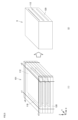
- FIG. 5 shows part of the process for manufacturing a quadrilateral sintered body in which each layer is formed in a quadrilateral shape and the whole is a rectangular parallelepiped.
- the cut points c1 to c4 are indicated by thick lines.
- both side surfaces of green sheet laminate 101 are cut at cutting points c1 and c2 so as to have a predetermined width.
- the cutting point c2 is a position where the positive electrode green sheet 112 is cut and the negative electrode green sheet 116 is not cut.
- the cutting point c1 is a position where the negative electrode green sheet 116 is cut and the positive electrode green sheet 112 is not cut.
- the positive electrode green sheet 112 or the negative electrode green sheet 116 can be cut so that the distance w1 (FIG. 3) from the ends to the side surfaces (cutting points c1, c2) is 0.5 mm. Subsequently, the front and back surfaces of the green sheet laminate 101 are cut at cutting points c3 and c4 so as to obtain a laminate having a predetermined depth. At this time, the positive electrode green sheet 112 and the negative electrode green sheet 116 are cut so as to include the entire depth direction and the separator green sheet 120 extends along the outer edge thereof. That is, the cutting points c3 and c4 are positions where only the separator green sheet 120 is cut, and the positive electrode green sheet 112 and the negative electrode green sheet 116 are not cut.
- degreasing and firing are performed to obtain an integrated sintered body 9 (FIG. 5(2)) having an insulating ceramic part on the periphery of the laminate.
- Degreasing and baking can be carried out under known conditions and methods.
- the thickness and width of each layer in the obtained integrally sintered body can be confirmed, for example, by polishing the laminated integrally sintered body with a sec-cross section polisher and observing the resulting cross section with an SEM.
- the positive electrode current collector 14 and the negative electrode current collector 18 are attached to the first side surface s1 and the second side surface s2 of the sintered body 9, respectively.
- a conductive material can be used for the positive electrode current collector 14 and the negative electrode current collector 18, and for example, aluminum foil, copper foil, or the like may be used.
- the positive electrode current collector 14 is attached so as to cover the entire first side surface s ⁇ b>1 and can be configured to extend to the lower surface of the sintered body 9 .
- the negative electrode current collector 18 may be attached so as to cover the entire second side surface s ⁇ b>2 and may be configured to extend over the upper surface of the sintered body 9 .
- a conductive adhesive can be used to bond between the sintered body 9 and the positive electrode current collector 14 and between the sintered body 9 and the negative electrode current collector 18 .
- a conductive carbon paste can be used as the conductive adhesive.
- the thickness of the conductive adhesive layer is not particularly limited as long as it exhibits an effect as an adhesive layer and does not interfere with the effects of the invention, but can be, for example, about 1 to 500 ⁇ m.
- a lithium secondary battery can be obtained by housing the electrode obtained by the above manufacturing method in the interior of the exterior body according to known methods and conditions, and encapsulating the electrolyte.
- the sintered body that constitutes the electrode included in the lithium secondary battery according to the present disclosure may be, for example, a round shape in addition to the square shape shown in the first embodiment.
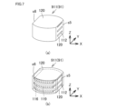
- 6 and 7 show part of the process of manufacturing a sintered body 91 which is round and wholly cylindrical. As shown in FIG. 7, the sintered body 91 has a shape in which a portion of a cylinder is cut parallel to the tangential line and two opposing side surfaces s5 and s6 are formed. ”.
- the sintered body 91 has substantially the same configuration as the sintered body 9 except for its shape. Differences will be mainly described below.
- FIG. 6(a) is a perspective view showing the appearance of the green sheet laminate 911 during the manufacturing process of the sintered body 91
- FIG. 6(b) is a schematic diagram showing the laminate structure inside the green sheet laminate 911.
- the positive electrode green sheet 112, the negative electrode green sheet 116, and the separator green sheet 120, which constitute each layer of the green sheet laminate 911 the same green sheets as those constituting the green sheet laminate 101 can be used, except that their shapes are different. can. Also, the stacking order can be the same as that of the green sheet laminate 101 .
- each of the positive electrode green sheet 112 and the negative electrode green sheet 116 included in the green sheet laminate 911 has a shape in which a part of a circle is cut parallel to the tangential line.
- the positive electrode green sheets 112 and the negative electrode green sheets 116 are alternately laminated with circular separator green sheets 120 interposed therebetween.
- the positive electrode green sheet 112 and the negative electrode green sheet 116 are arranged such that the cut portions are located on opposite sides of each other.
- the separator green sheet 120 covers the entire periphery of the laminated portion.
- FIGS. 6A and 6B show the cut points c8 and c9 are indicated by thick lines.
- FIGS. 7A and 7B show the state after cutting. 6 and 7, the cutting point c8 is a position where the positive electrode green sheet 112 is cut without overlapping with the negative electrode green sheet 116. As shown in FIG. Moreover, the cut portion c8 is parallel to the cut portion of the negative electrode green sheet 116 .
- a side surface s5 is obtained in which the positive electrode green sheet 112 and the separator green sheet 120 are exposed and the negative electrode green sheet 116 is not exposed.
- the cutting point c9 is a position that does not overlap the positive electrode green sheet 112 and where the negative electrode green sheet 116 is cut. Moreover, the cut portion c9 is parallel to the cut portion of the positive electrode green sheet 112 .
- a side surface s6 is obtained in which the negative electrode green sheet 116 and the separator green sheet 120 are exposed and the positive electrode green sheet 112 is not exposed.
- degreasing and firing are performed to obtain an integrated sintered body 91 in which an insulating ceramic portion is formed on the periphery of the laminated portion.
- a current collector is connected to each of the side surfaces s5 and s6, and assembly is performed in the same manner as in Embodiment 1, whereby a lithium secondary battery can be obtained.
- the sintered body that constitutes the electrode contained in the lithium secondary battery according to the present disclosure is, in addition to the multilayer laminate type shown in Embodiments 1 and 2, one positive electrode layer and one negative electrode layer interposed with a separator. It may be a sintered body that is laminated by FIG. 8 is a schematic diagram showing part of the manufacturing process of the sintered body 92 included in the lithium secondary battery according to the present disclosure. Referring to FIG. 8(4), sintered body 92 includes laminate 111 as a laminated portion in which one layer of positive electrode layer 12 and one layer of negative electrode layer 16 are laminated with separator 20 interposed therebetween.
- the sintered body 92 has a cylindrical shape, the negative electrode layer 16 is exposed on the upper surface of the sintered body 92 , and the positive electrode layer 12 is exposed on the lower surface of the sintered body 92 . Moreover, the entire periphery of the laminated body 111 included in the sintered body 92 is covered with the insulating layer 52 as the insulating ceramics portion. That is, the positive electrode layer or the negative electrode layer is not exposed on the outer peripheral surface of the sintered body 92 .
- a composition similar to that of the sintered body 9 can be used for the composition constituting each layer included in the sintered body 92 .
- round positive electrode green sheet 212 and negative electrode green sheet 116 are prepared.
- the positive electrode green sheet 212 and the negative electrode green sheet 116 may be composed of a single layer sheet, or may be composed of a plurality of sheets laminated and pressure-bonded so as to have a desired thickness.
- a separator green sheet 121 formed with holes 220 having diameters corresponding to the positive electrode green sheet 212 and the negative electrode green sheet 116, and a separator green sheet 120 without holes. prepare.
- the positive electrode green sheet 212 and the negative electrode green sheet 116 are arranged so as to fit in the holes 220 of the separator green sheet 121 , and the separator green sheet 120 is arranged between the positive electrode green sheet 212 and the negative electrode green sheet 116 .
- compression is performed to obtain the green sheet laminate 912 .
- the green sheet laminate 912 is cut.
- the cutting portion includes the positive electrode green sheet 212 and the negative electrode green sheet 216, and the cutting portion is adjusted so that the separator green sheet 120 is positioned on the periphery thereof, and the green sheet laminate 912 is cut into a cylindrical shape.
- An electrode can be formed by connecting current collectors to each of the negative electrode layer 16 exposed on the upper surface of the sintered body 92 and the positive electrode layer 12 exposed on the lower surface. Furthermore, it can be assembled according to a known method to obtain a lithium secondary battery.
- LCO green sheet positive electrode green sheet
- Co 3 O 4 powder manufactured by Seido Chemical Industry Co., Ltd.
- Li 2 CO 3 powder weighed so that the molar ratio of Li/Co was 1.01. (manufactured by Honjo Chemical Co., Ltd.) was mixed and then held at 780° C. for 5 hours.
- the obtained powder was pulverized with a pot mill so that the volume-based D50 was 0.4 ⁇ m to obtain a powder composed of LCO plate-like particles.
- 8 parts by weight of a binder polyvinyl butyral: product number BM-2, manufactured by Sekisui Chemical Co., Ltd.
- a plasticizer 2 parts by weight of (DOP: Di(2-ethylhexyl) phthalate, manufactured by Kurogane Kasei Co., Ltd.) and 4.5 parts by weight of a dispersant (product name: Rhodol SP-O30, manufactured by Kao Corporation) were mixed.
- An LCO slurry was prepared by stirring the obtained mixture under reduced pressure to remove air bubbles and adjusting the viscosity to 4000 cP.
- An LCO green sheet was formed by sheet-forming the prepared slurry on a PET film. The thickness of the positive electrode layer after firing was adjusted to 24 ⁇ m.
- LTO green sheet negative electrode green sheet
- LTO powder volume-based D50 particle size 0.06 ⁇ m, manufactured by Sigma-Aldrich Japan LLC
- binder polyvinyl butyral: product number BM-2, manufactured by Sekisui Chemical Co., Ltd.
- plasticizer DOP: Di (2-ethylhexyl) phthalate, manufactured by Kurogane Kasei Co., Ltd.
- a dispersant product name: Rheodol SP-O30, manufactured by Kao Corporation
- An LTO slurry was prepared by stirring the obtained negative electrode raw material mixture under reduced pressure to remove air bubbles and adjusting the viscosity to 4000 cP.
- An LTO green sheet was formed by forming the prepared slurry into a sheet on a PET film. The thickness of the negative electrode layer after firing was adjusted to 10 ⁇ m.
- a slurry was prepared by stirring the obtained raw material mixture under reduced pressure to remove air bubbles and adjusting the viscosity to 4000 cP.
- a separator green sheet was formed by forming the prepared slurry into a sheet on a PET film. The thickness of the separator positioned between the positive electrode layer and the negative electrode layer was set to 25 ⁇ m after firing. The thickness of the separator (insulating layer) located next to the positive electrode layer was set to 24 ⁇ m after firing. The thickness of the separator (insulating layer) located next to the negative electrode layer was set to 20 ⁇ m after firing.
- Sheet cutting 1 The green sheets obtained in were cut for lamination.
- the positive electrode green sheet and the negative electrode green sheet were cut into squares of 20 mm ⁇ 9.5 mm.
- the separator green sheet was cut into squares of 25 mm ⁇ 25 mm.
- the cutting position is such that, in the width direction of the laminate, the end faces of the positive electrode layer green sheet and the separator green sheet are exposed on one side, and the end faces of the negative electrode layer green sheet and the separator green sheet are exposed on the other side. disconnected.
- the whole depth direction (9.5 mm) of the positive electrode green sheet and the negative electrode green sheet is included in the laminate after cutting, and the total thickness of the insulating ceramic part is 0.5 mm. disconnected. That is, the laminate was cut so that only the separator green sheets were exposed on the front and back sides of the laminate.
- conductive carbon paste Binder (CMC: MAC350HC, manufactured by Nippon Paper Industries Co., Ltd.) is weighed to 1.2 wt% with respect to pure water, and dissolved with a stirrer to obtain a 1.2 wt% CMC solution.
- Ta A carbon dispersion (product number: BPW-229, manufactured by Nippon Graphite Co., Ltd.) and a dispersing agent solution (product number: LB-300, manufactured by Showa Denko KK) were prepared.
- the carbon dispersion, the dispersant solution, and the 1.2 wt% CMC solution were weighed so that the ratio was 0.22:0.29:1, and mixed by a rotation/revolution mixer to obtain a conductive carbon paste. was prepared.
- FIG. 9 shows a schematic perspective view of the external appearance of the lithium secondary battery.
- the electrolytic solution LiPF 6 was dissolved to a concentration of 1.5 mol/L in an organic solvent in which propylene carbonate (PC) and ⁇ -butyrolactone (GBL) were mixed at a volume ratio of 1:3. Using.
- Example 1 A lithium secondary battery was produced in the same manner as in Example 1, except for the position where the green sheet was cut and the green sheet laminate was cut.
- the positive electrode green sheet and the negative electrode green sheet were cut into squares of 20 mm ⁇ 20 mm.
- the separator green sheet was cut into squares of 25 mm ⁇ 25 mm.
- various green sheets were laminated and pressed in the same manner as in Example 1.
- the pressed laminate was placed at a position where one of the two side surfaces exposed the positive electrode layer and the separator (the negative electrode layer was not exposed) and the other side was the position where the negative electrode layer and the separator were exposed (the positive electrode layer was not exposed). disconnected.
- the front and back surfaces of the laminate were cut at positions where the positive electrode layer, the separator and the negative electrode layer were exposed.
- the size of the green sheet laminate after cutting was set to 10 mm ⁇ 10 mm as in Example 1.
- Example 2 As in Example 1, a positive electrode green sheet, a negative electrode green sheet and a separator green sheet were produced. In the green sheet cutting process, the positive electrode green sheet and the negative electrode green sheet were each punched out with a circular puncher having a diameter of 15.5 mm to obtain a circular green sheet. Further, each circular green sheet was cut linearly in parallel with the tangent line at the point at a position 2 mm from one point on the end face toward the center. Next, in the same stacking order as in Example 1, various green sheets were stacked such that the number of cells formed in the stack was 15. As shown in FIG. 6, the positive electrode green sheet and the negative electrode green sheet were arranged so that their cut end surfaces were positioned to face each other across the center of the circle.
- the green sheet laminate was pressed under the same conditions as in Example 1 to press the green sheets together.
- the pressed green sheet laminate was punched out with a hand puncher having a diameter of 16 mm.
- two points were cut along two parallel straight lines. The cutting positions were such that the positive electrode and the separator were exposed on one end face and the negative electrode layer was not exposed, and the negative electrode layer and the separator were exposed and the positive electrode layer was not exposed on the other end face.
- degreasing and firing were carried out in the same manner as in Example 1 to obtain a round multilayer laminated sintered body whose periphery was covered with a separator (insulating ceramic portion).
- An aluminum foil as a positive electrode current collector was placed on the exposed surface of the positive electrode and the separator with a conductive carbon paste interposed therebetween. Further, an aluminum foil as a negative electrode current collector was placed on the surface where the negative electrode and the separator were exposed, with a conductive carbon paste interposed therebetween.
- a lithium secondary battery was assembled in the same manner as in Example 1.
- Example 2 As in Example 1, a positive electrode green sheet, a negative electrode green sheet and a separator green sheet were produced. As in Comparative Example 1, the positive electrode green sheet and the negative electrode green sheet were cut into squares of 20 mm ⁇ 20 mm. The separator green sheet was cut into squares of 25 mm ⁇ 25 mm. After that, various green sheets were laminated and pressed in the same manner as in Example 1. Next, various green sheets were laminated in the same order and position as in Example 1 so that the number of cells formed in the laminate was 15. Subsequently, the green sheet laminate was pressed under the same conditions as in Example 1 to press the green sheets together. The pressed green sheet laminate was punched out with a hand puncher having a diameter of 16 mm.
- Example 3 A positive electrode green sheet was produced in the same manner as in Example 1, except that the thickness after firing was 100 ⁇ m. Further, a negative electrode green sheet was produced in the same manner as in Example 1, except that the thickness after firing was set to 100 ⁇ m. A separator green sheet was produced in the same manner as in Example 1. In the lamination, seven positive electrode green sheets and three negative electrode green sheets cut to 20 mm ⁇ 20 mm were separately laminated, and pressed at 100 kgf/cm 2 by CIP to crimp the green sheets together. Then, they were punched out with a round puncher having a diameter of 15.5 mm to obtain round positive electrode temporary laminates and negative electrode temporary laminates shown in FIG. 8 (1).
- the separator green sheet was also laminated and crimped in the same manner so as to have the same thickness as the positive electrode temporary laminate and the negative electrode temporary laminate, and punched with a round puncher with a diameter of 15.5 mm [Fig. 8] ( 2), a separator temporary laminate having a round hole with a diameter of 15.5 mm was obtained.
- the positive electrode temporary laminate and the negative electrode temporary laminate were inserted into round holes of the separator temporary laminate having the same thickness as the respective thicknesses, and furthermore, a stacking and pressure bonding process was performed with a separator green sheet sandwiched therebetween.
- the resulting laminate was punched into a cylindrical shape using a round puncher with a diameter of 16 mm. In this way, as shown in FIG.
- an unsintered green sheet laminate was obtained in which an insulating ceramic portion of 0.25 mm was formed on the peripheral edge of the laminated portion of 15.5 mm in diameter.
- Debinding and sintering were performed in the same manner as in Example 1 to obtain a sintered body in which one positive electrode layer, a separator, and one negative electrode layer were integrally sintered and provided with an insulating ceramic part on the periphery.
- a lithium secondary battery was produced in the same manner as in Example 1.
- Example 3 A positive electrode green sheet and a negative electrode green sheet were produced in the same manner as in Example 3.
- a separator green sheet was produced in the same manner as in Example 1. Seven positive electrode green sheets each cut to 20 mm ⁇ 20 mm, one separator green sheet, and three negative electrode green sheets were laminated in this order, and pressed by CIP at 100 kgf/cm 2 to crimp the green sheets together. This laminate was punched into a cylindrical shape using a round puncher with a diameter of 16 mm to obtain an unsintered green sheet laminate. Debinding and sintering were performed in the same manner as in Example 1 to obtain a round sintered body in which one positive electrode layer, a separator, and one negative electrode layer were integrally sintered. The positive electrode layer, the separator, and the negative electrode layer were exposed at the periphery of the sintered body.
- a lithium secondary battery was produced in the same manner as in Example 1.
- Evaluation 1 Evaluation of battery performance (0.2C discharge capacity evaluation) Using the obtained battery, the battery capacity was confirmed under an environment of 25°C. Charging was performed at a constant current of 0.2C until the voltage reached 2.7V. Discharge was performed at a constant current of 0.2C until the voltage reached 1.5V. The second cycle of charging and discharging was performed under the same conditions as the first cycle, and the discharge capacity of this second cycle was taken as the 0.2C discharge capacity.
- Example 1 and Comparative Example 1 have multi-layer rectangular electrodes including the same number of cells, and differ only in the presence or absence of an insulating ceramic part at the periphery of the laminated part.
- Example 2 and Comparative Example 2 both have multi-layer circular electrodes containing the same number of cells, and differ only in the presence or absence of the insulating ceramics portion at the periphery of the laminated portion.
- Example 3 and Comparative Example 3 comprise an electrode comprising one positive electrode layer, a separator and one negative electrode layer.
- Example 3 and Comparative Example 3 differ in the presence or absence of the insulating ceramics portion at the periphery.
- Electrode 1 Laminated body, 5 Electrode, 10 Lithium secondary battery, 12 Positive electrode layer, 16 Negative electrode layer, 14 Positive electrode current collector, 18 Negative electrode current collector, 20 Separator, 22 Electrolyte, 24 Exterior body, 24a Positive electrode can, 24b Negative electrode Can, 24c gasket, 51, 52 insulating layer, 9, 91, 92 sintered body, 101 green sheet laminate, 112 positive electrode green sheet, 116 negative electrode green sheet, 120 separator green sheet.
Landscapes
- Chemical & Material Sciences (AREA)
- Chemical Kinetics & Catalysis (AREA)
- Electrochemistry (AREA)
- General Chemical & Material Sciences (AREA)
- Engineering & Computer Science (AREA)
- Manufacturing & Machinery (AREA)
- Inorganic Chemistry (AREA)
- Materials Engineering (AREA)
- Ceramic Engineering (AREA)
- Secondary Cells (AREA)
- Battery Electrode And Active Subsutance (AREA)
Priority Applications (3)
| Application Number | Priority Date | Filing Date | Title |
|---|---|---|---|
| CN202280089317.XA CN118661309A (zh) | 2022-02-24 | 2022-12-26 | 锂二次电池 |
| JP2024502872A JPWO2023162454A1 (https=) | 2022-02-24 | 2022-12-26 | |
| US18/787,052 US20240387878A1 (en) | 2022-02-24 | 2024-07-29 | Lithium secondary battery |
Applications Claiming Priority (2)
| Application Number | Priority Date | Filing Date | Title |
|---|---|---|---|
| JP2022-027151 | 2022-02-24 | ||
| JP2022027151 | 2022-02-24 |
Related Child Applications (1)
| Application Number | Title | Priority Date | Filing Date |
|---|---|---|---|
| US18/787,052 Continuation US20240387878A1 (en) | 2022-02-24 | 2024-07-29 | Lithium secondary battery |
Publications (1)
| Publication Number | Publication Date |
|---|---|
| WO2023162454A1 true WO2023162454A1 (ja) | 2023-08-31 |
Family
ID=87765585
Family Applications (1)
| Application Number | Title | Priority Date | Filing Date |
|---|---|---|---|
| PCT/JP2022/047935 Ceased WO2023162454A1 (ja) | 2022-02-24 | 2022-12-26 | リチウム二次電池 |
Country Status (4)
| Country | Link |
|---|---|
| US (1) | US20240387878A1 (https=) |
| JP (1) | JPWO2023162454A1 (https=) |
| CN (1) | CN118661309A (https=) |
| WO (1) | WO2023162454A1 (https=) |
Citations (3)
| Publication number | Priority date | Publication date | Assignee | Title |
|---|---|---|---|---|
| JP2019164980A (ja) * | 2017-10-20 | 2019-09-26 | セントラル硝子株式会社 | 複合体電極及び全固体リチウム電池 |
| WO2020203620A1 (ja) * | 2019-03-29 | 2020-10-08 | 株式会社村田製作所 | 固体電池 |
| WO2021024557A1 (ja) * | 2019-08-06 | 2021-02-11 | 株式会社村田製作所 | 蓄電デバイス |
-
2022
- 2022-12-26 JP JP2024502872A patent/JPWO2023162454A1/ja not_active Ceased
- 2022-12-26 WO PCT/JP2022/047935 patent/WO2023162454A1/ja not_active Ceased
- 2022-12-26 CN CN202280089317.XA patent/CN118661309A/zh active Pending
-
2024
- 2024-07-29 US US18/787,052 patent/US20240387878A1/en not_active Abandoned
Patent Citations (3)
| Publication number | Priority date | Publication date | Assignee | Title |
|---|---|---|---|---|
| JP2019164980A (ja) * | 2017-10-20 | 2019-09-26 | セントラル硝子株式会社 | 複合体電極及び全固体リチウム電池 |
| WO2020203620A1 (ja) * | 2019-03-29 | 2020-10-08 | 株式会社村田製作所 | 固体電池 |
| WO2021024557A1 (ja) * | 2019-08-06 | 2021-02-11 | 株式会社村田製作所 | 蓄電デバイス |
Also Published As
| Publication number | Publication date |
|---|---|
| JPWO2023162454A1 (https=) | 2023-08-31 |
| US20240387878A1 (en) | 2024-11-21 |
| CN118661309A (zh) | 2024-09-17 |
Similar Documents
| Publication | Publication Date | Title |
|---|---|---|
| JP7189163B2 (ja) | リチウム二次電池 | |
| CN109792079B (zh) | 全固体锂离子二次电池 | |
| JP7280379B2 (ja) | リチウム二次電池及びその充電状態の測定方法 | |
| CN113454826A (zh) | 层叠型全固体二次电池及其制造方法 | |
| US12046711B2 (en) | Lithium secondary battery | |
| JP6985509B2 (ja) | リチウム二次電池 | |
| JP7742301B2 (ja) | リチウム二次電池 | |
| JP7268142B2 (ja) | リチウム二次電池 | |
| WO2023162454A1 (ja) | リチウム二次電池 | |
| WO2019221142A1 (ja) | リチウム二次電池 | |
| WO2019221144A1 (ja) | リチウム二次電池 | |
| JP7193622B2 (ja) | リチウム二次電池 | |
| WO2019221143A1 (ja) | リチウム二次電池 | |
| JP7751651B2 (ja) | リチウム二次電池 | |
| JP7710541B2 (ja) | リチウム二次電池 | |
| US20240291042A1 (en) | Lithium secondary battery | |
| CN112889163B (zh) | 纽扣型锂二次电池 | |
| WO2024203868A1 (ja) | リチウムイオン電池のための電極およびリチウムイオン電池 | |
| WO2024203869A1 (ja) | リチウムイオン電池 | |
| WO2022208982A1 (ja) | コイン形リチウムイオン二次電池 | |
| WO2024203506A1 (ja) | リチウムイオン電池 | |
| JP7612835B2 (ja) | リチウム二次電池 | |
| WO2025033556A1 (ja) | 電気化学素子およびその製造方法 | |
| JP2026021871A (ja) | リチウムイオン電池の正極材料、電極およびリチウムイオン電池 |
Legal Events
| Date | Code | Title | Description |
|---|---|---|---|
| 121 | Ep: the epo has been informed by wipo that ep was designated in this application |
Ref document number: 22928969 Country of ref document: EP Kind code of ref document: A1 |
|
| WWE | Wipo information: entry into national phase |
Ref document number: 202280089317.X Country of ref document: CN |
|
| ENP | Entry into the national phase |
Ref document number: 2024502872 Country of ref document: JP Kind code of ref document: A |
|
| NENP | Non-entry into the national phase |
Ref country code: DE |
|
| 122 | Ep: pct application non-entry in european phase |
Ref document number: 22928969 Country of ref document: EP Kind code of ref document: A1 |