WO2023162454A1 - リチウム二次電池 - Google Patents
リチウム二次電池 Download PDFInfo
- Publication number
- WO2023162454A1 WO2023162454A1 PCT/JP2022/047935 JP2022047935W WO2023162454A1 WO 2023162454 A1 WO2023162454 A1 WO 2023162454A1 JP 2022047935 W JP2022047935 W JP 2022047935W WO 2023162454 A1 WO2023162454 A1 WO 2023162454A1
- Authority
- WO
- WIPO (PCT)
- Prior art keywords
- electrode layer
- positive electrode
- negative electrode
- sintered body
- separator
- Prior art date
Links
Images


Classifications
-
- H—ELECTRICITY
- H01—ELECTRIC ELEMENTS
- H01M—PROCESSES OR MEANS, e.g. BATTERIES, FOR THE DIRECT CONVERSION OF CHEMICAL ENERGY INTO ELECTRICAL ENERGY
- H01M10/00—Secondary cells; Manufacture thereof
- H01M10/05—Accumulators with non-aqueous electrolyte
- H01M10/052—Li-accumulators
-
- H—ELECTRICITY
- H01—ELECTRIC ELEMENTS
- H01M—PROCESSES OR MEANS, e.g. BATTERIES, FOR THE DIRECT CONVERSION OF CHEMICAL ENERGY INTO ELECTRICAL ENERGY
- H01M10/00—Secondary cells; Manufacture thereof
- H01M10/05—Accumulators with non-aqueous electrolyte
- H01M10/058—Construction or manufacture
- H01M10/0585—Construction or manufacture of accumulators having only flat construction elements, i.e. flat positive electrodes, flat negative electrodes and flat separators
-
- H—ELECTRICITY
- H01—ELECTRIC ELEMENTS
- H01M—PROCESSES OR MEANS, e.g. BATTERIES, FOR THE DIRECT CONVERSION OF CHEMICAL ENERGY INTO ELECTRICAL ENERGY
- H01M4/00—Electrodes
- H01M4/02—Electrodes composed of, or comprising, active material
- H01M4/13—Electrodes for accumulators with non-aqueous electrolyte, e.g. for lithium-accumulators; Processes of manufacture thereof
- H01M4/131—Electrodes based on mixed oxides or hydroxides, or on mixtures of oxides or hydroxides, e.g. LiCoOx
-
- H—ELECTRICITY
- H01—ELECTRIC ELEMENTS
- H01M—PROCESSES OR MEANS, e.g. BATTERIES, FOR THE DIRECT CONVERSION OF CHEMICAL ENERGY INTO ELECTRICAL ENERGY
- H01M4/00—Electrodes
- H01M4/02—Electrodes composed of, or comprising, active material
- H01M4/36—Selection of substances as active materials, active masses, active liquids
- H01M4/48—Selection of substances as active materials, active masses, active liquids of inorganic oxides or hydroxides
- H01M4/485—Selection of substances as active materials, active masses, active liquids of inorganic oxides or hydroxides of mixed oxides or hydroxides for inserting or intercalating light metals, e.g. LiTi2O4 or LiTi2OxFy
-
- H—ELECTRICITY
- H01—ELECTRIC ELEMENTS
- H01M—PROCESSES OR MEANS, e.g. BATTERIES, FOR THE DIRECT CONVERSION OF CHEMICAL ENERGY INTO ELECTRICAL ENERGY
- H01M4/00—Electrodes
- H01M4/02—Electrodes composed of, or comprising, active material
- H01M4/36—Selection of substances as active materials, active masses, active liquids
- H01M4/48—Selection of substances as active materials, active masses, active liquids of inorganic oxides or hydroxides
- H01M4/50—Selection of substances as active materials, active masses, active liquids of inorganic oxides or hydroxides of manganese
- H01M4/505—Selection of substances as active materials, active masses, active liquids of inorganic oxides or hydroxides of manganese of mixed oxides or hydroxides containing manganese for inserting or intercalating light metals, e.g. LiMn2O4 or LiMn2OxFy
-
- H—ELECTRICITY
- H01—ELECTRIC ELEMENTS
- H01M—PROCESSES OR MEANS, e.g. BATTERIES, FOR THE DIRECT CONVERSION OF CHEMICAL ENERGY INTO ELECTRICAL ENERGY
- H01M4/00—Electrodes
- H01M4/02—Electrodes composed of, or comprising, active material
- H01M4/36—Selection of substances as active materials, active masses, active liquids
- H01M4/48—Selection of substances as active materials, active masses, active liquids of inorganic oxides or hydroxides
- H01M4/52—Selection of substances as active materials, active masses, active liquids of inorganic oxides or hydroxides of nickel, cobalt or iron
- H01M4/525—Selection of substances as active materials, active masses, active liquids of inorganic oxides or hydroxides of nickel, cobalt or iron of mixed oxides or hydroxides containing iron, cobalt or nickel for inserting or intercalating light metals, e.g. LiNiO2, LiCoO2 or LiCoOxFy
-
- Y—GENERAL TAGGING OF NEW TECHNOLOGICAL DEVELOPMENTS; GENERAL TAGGING OF CROSS-SECTIONAL TECHNOLOGIES SPANNING OVER SEVERAL SECTIONS OF THE IPC; TECHNICAL SUBJECTS COVERED BY FORMER USPC CROSS-REFERENCE ART COLLECTIONS [XRACs] AND DIGESTS
- Y02—TECHNOLOGIES OR APPLICATIONS FOR MITIGATION OR ADAPTATION AGAINST CLIMATE CHANGE
- Y02E—REDUCTION OF GREENHOUSE GAS [GHG] EMISSIONS, RELATED TO ENERGY GENERATION, TRANSMISSION OR DISTRIBUTION
- Y02E60/00—Enabling technologies; Technologies with a potential or indirect contribution to GHG emissions mitigation
- Y02E60/10—Energy storage using batteries
Definitions
- a positive electrode layer composed of a sintered body of lithium composite oxide, a negative electrode layer composed of a sintered body containing titanium, and a ceramic disposed between the positive electrode layer and the negative electrode layer A separator is known.
- US Pat. No. 6,300,000 discloses a lithium secondary battery whose electrodes include an integral sintered plate in which a positive electrode layer, a ceramic separator and a negative electrode layer are bonded together.
- Patent Document 2 discloses an all-solid battery having a laminate in which a plurality of positive electrode layers and a plurality of negative electrode layers are alternately laminated via solid electrolyte layers.
- the laminate disclosed in Patent Document 2 is characterized in that a buffer layer is provided in the solid electrolyte layer.
- one of the positive electrode layer and the negative electrode layer is exposed at each of a pair of ends and an external terminal is connected to each of the pair of ends when viewed from above in the stacking direction.
- a lithium secondary battery with a large discharge capacity and low self-discharge is desired.
- one of the objects of the invention according to the present disclosure is to provide a lithium secondary battery with a large discharge capacity and little self-discharge.
- a lithium secondary battery according to the present disclosure includes a positive electrode layer, a negative electrode layer, and a separator, and includes a sintered body including a laminated portion in which the positive electrode layer and the negative electrode layer are laminated with the separator interposed therebetween.
- the sintered body includes an insulating ceramic part that covers at least part of the peripheral edge of the laminated part and extends over at least part of the laminated structure that is exposed at the peripheral edge of the laminated part.
- a lithium secondary battery with a large discharge capacity and little self-discharge is provided.
- FIG. 1 is a schematic cross-sectional view showing a lithium secondary battery according to the present disclosure.
- FIG. 2 is a schematic perspective view showing a sintered body included in a lithium secondary battery according to the present disclosure;
- FIG. 2(a) is a perspective view of the appearance, and
- FIG. 2(b) is a schematic diagram showing the internal structure.
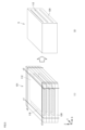
- FIG. 3 is a schematic cross-sectional perspective view showing a laminated portion in a sintered body included in a lithium secondary battery according to the present disclosure.
- FIG. 4 is a schematic diagram showing a part of the manufacturing process of the sintered body included in the lithium secondary battery according to the present disclosure.
- FIG. 5 is a schematic diagram showing a part of the manufacturing process of the sintered body included in the lithium secondary battery according to the present disclosure.
- FIG. 1 is a schematic cross-sectional view showing a lithium secondary battery according to the present disclosure.
- FIG. 2 is a schematic perspective view showing a sintered body included in a lithium secondary battery according to the present
- FIG. 6 is a schematic diagram showing one state in the manufacturing process of the sintered body included in the lithium secondary battery according to the present disclosure.
- FIG. 7 is a schematic diagram showing one state in the manufacturing process of the sintered body included in the lithium secondary battery according to the present disclosure.
- FIG. 8 is a schematic diagram showing a part of the manufacturing process of the sintered body included in the lithium secondary battery according to the present disclosure.
- FIG. 9 is a schematic perspective view showing the appearance of a lithium secondary battery according to the present disclosure.
- a lithium secondary battery according to the present disclosure includes a positive electrode layer, a negative electrode layer, and a separator, and includes a sintered body including a laminated portion in which the positive electrode layer and the negative electrode layer are laminated via the separator.
- the sintered body includes an insulating ceramic part that covers at least part of the peripheral edge of the laminated part and extends over at least part of the laminated structure that is exposed at the peripheral edge of the laminated part.
- a positive electrode layer composed of a sintered body of lithium composite oxide, a negative electrode layer composed of a sintered body containing titanium, and a ceramic separator disposed between the positive electrode layer and the negative electrode layer.
- Lithium secondary batteries are known.
- a current collector is connected to each of the positive electrode layer and the negative electrode layer to form an electrode.
- the positive electrode-side current collector is connected to the lower surface of the positive electrode layer
- the negative electrode-side current collector is connected to the upper surface of the positive electrode layer via the conductive carbon layer.
- These current collectors are arranged so as to cover the main surfaces of the positive electrode layer and the negative electrode layer.
- the end faces of the positive electrode layer, the separator and the negative electrode layer are exposed at the periphery of the sintered body including the positive electrode layer, the separator and the negative electrode layer.
- the inventors conducted studies with the aim of obtaining a lithium secondary battery with little self-discharge while maintaining the high capacity obtained in a battery including an electrode composed of a sintered body. They also found that self-discharge can be remarkably reduced while maintaining the same high capacity as in the past by covering the periphery of the laminated portion, where the laminated structure was exposed in the prior art, with an insulating ceramic portion.
- the insulating ceramics portion may be sintered integrally with the laminated portion. Since the laminated portion and the insulating ceramics portion are integrally sintered, the effect of providing the insulating ceramics portion can be reliably obtained, and the electrode can be manufactured efficiently and stably.
- the insulating ceramic part and the separator may be made of the same composition.
- the electrode can be efficiently manufactured.
- separation between layers is less likely to occur during sintering, and electrodes can be stably manufactured.
- the surface of the sintered body includes a surface covered with the insulating ceramic part, a surface where the positive electrode layer is exposed and the negative electrode layer is not exposed, and a surface where the negative electrode layer is exposed. and a surface on which the positive electrode layer is not exposed.
- the positive electrode-side current collector and the negative electrode-side current collector are respectively arranged on the surface where the positive electrode layer is exposed and the surface where the negative electrode layer is exposed, and the end surfaces of the positive electrode layer and the negative electrode layer are the surfaces of the electrodes. It can be configured so that it is not exposed to According to this structure, self-discharge can be reduced more reliably.
- the laminated portion includes a plurality of positive electrode layers, a plurality of negative electrode layers, and a separator, and the positive electrode layers and the negative electrode layers are alternately laminated with the separators interposed therebetween.
- the sintered body contained in the lithium secondary battery may be a multi-layer laminated sintered body in which a plurality of cells are contained in one sintered body.
- the number of laminations in a sintered body increases, it becomes more difficult to accurately maintain the intervals between the layers. . Therefore, it is possible to obtain an electrode with little self-discharge even though it is a multi-layered sintered body.
- the positive electrode layer may be composed of a lithium composite oxide sintered body
- the negative electrode layer may be composed of a titanium-containing sintered body.
- the positive electrode layer composed of a lithium composite oxide sintered body and the negative electrode layer composed of a titanium-containing sintered body are known structures, and by combining them with the above structures, more stable lithium with suppressed self-discharge can be obtained. A secondary battery is obtained.
- FIG. 1 is a schematic cross-sectional view showing the structure of a lithium secondary battery 10 that is an example of an embodiment according to the present disclosure.
- FIG. 2 is a schematic perspective view showing the sintered body 9 included in the lithium secondary battery 10 taken out. 1 and 2, the X-axis direction is the width direction of the laminated body 1 to the sintered body 9, the Y-axis direction is the depth direction of the laminated body 1 to the sintered body 9, and the Z-axis direction is the laminated body. 1 to the sintered body 9 are referred to as a stacking direction or a thickness direction.
- the surface of the uppermost layer in the stacking direction of the laminate 1 is referred to as the upper surface
- the surface of the lowermost layer in the stacking direction is referred to as the lower surface
- the surfaces where all the laminated layers are exposed are referred to as the front surface and the rear surface.
- the front and back surfaces are planes parallel to the XZ plane.
- the surface where the laminate structure is exposed the surface extending between the front surface and the rear surface, and extending along the depth direction is referred to as a side surface.
- a side surface is a surface parallel to the YZ plane. Surfaces other than the top and bottom surfaces, that is, the front and rear surfaces in addition to the side surfaces are sometimes referred to as side surfaces.
- the terms "upper surface”, “lower surface”, “side surface”, etc. are relative terms used for convenience of explanation in this specification, and the direction of arrangement and direction of use in the lithium secondary battery is not limited to these directions.
- the lithium secondary battery 10 has the electrode 5 housed inside the exterior body 24 .
- the electrode 5 includes a sintered body 9, and a positive electrode current collector 14 and a negative electrode current collector 18 attached to both side surfaces of the sintered body 9, respectively.
- the sintered body 9 includes a layered body 1 as a layered portion and an insulating layer 51 (FIG. 2) as an insulating ceramics portion extending around the periphery of the layered body 1 .
- the laminate 1 is formed by laminating a plurality of positive electrode layers 12 , a plurality of negative electrode layers 16 and a separator 20 .
- the laminate 1 and the insulating layer 51 as a whole constitute a sintered body 9 that is one integrally sintered body.
- the positive electrode layers 12 and the negative electrode layers 16 are alternately stacked in the stacking direction.
- the separator 20 is interposed between the positive electrode layer 12 and the negative electrode layer 16 .
- the positive electrode layer 12 and the negative electrode layer 16 are separated from each other by the separator 20 .
- the positive electrode layer 12 is composed of, for example, a sintered body containing lithium cobaltate.
- the negative electrode layer 16 is composed of, for example, a titanium-containing sintered body.
- the separator 20 is made of ceramic.
- a sealed space is formed inside the exterior body 24 .
- the electrode 5 and the electrolytic solution 22 are accommodated in this closed space.
- an electrolytic solution 22 is sealed inside an outer package 24.
- the positive electrode layer 12 , the negative electrode layer 16 and the separator 20 are also impregnated with the electrolytic solution 22 .
- the exterior body 24 may be appropriately selected according to the type of the lithium secondary battery 10.
- lithium secondary battery 10 when lithium secondary battery 10 is in the form of a coin-shaped battery as shown in FIG.
- a negative electrode can 24b is crimped via a gasket 24c to form a closed space.
- the cathode can 24a and the anode can 24b may be made of metal such as stainless steel, but are not limited thereto.
- the gasket 24c may be an annular member made of insulating resin such as polypropylene, polytetrafluoroethylene, or PFA resin, and is not particularly limited.
- the lithium secondary battery 10 shown in FIG. 1 is in the form of a coin-shaped battery
- the form of the lithium secondary battery according to the present disclosure is not limited to the coin-shaped battery.
- other forms such as a thin secondary battery including a chip-type secondary battery and a pouch-type secondary battery may be used.
- the exterior body is a resin base material
- the battery elements that is, the electrodes 5 and the electrolyte solution 22
- the battery element may be sandwiched between a pair of resin films.
- the pair of resin films may be bonded together with an adhesive.
- the pair of resin films may be heat-sealed to each other by hot pressing.
- a separator made of a solid electrolyte may be employed as the separator, and may have a configuration that does not contain an electrolytic solution.
- the electrode 5 of the lithium secondary battery 10 includes a positive electrode current collector 14 connected to the sintered body 9 from the side surface to the bottom surface of the sintered body 9 .
- the lithium secondary battery 10 also includes a negative electrode current collector 18 connected to the sintered body 9 from the side surface to the upper surface of the sintered body 9 .
- the positive electrode current collector 14 and the negative electrode current collector 18 may be, for example, metal foils such as copper foil and aluminum foil. From the viewpoint of reducing contact resistance, it is preferable to provide a carbon layer (not shown) between each of the positive electrode current collector 14 and the negative electrode current collector 18 and the sintered body 9 .
- the carbon layer is preferably made of conductive carbon.
- a carbon layer can be formed, for example, by applying a conductive carbon paste to the surface of a metal foil used as a current collector.
- FIG. 2 is a schematic perspective view showing a sintered body 9 included in a lithium secondary battery according to the present disclosure.
- FIG. 2(a) shows the appearance
- FIG. 2(b) is a schematic diagram showing the structure of the layers included in the sintered body 9, including the inside.
- the sintered body 9 is a laminated portion in which a plurality of positive electrode layers 12, a plurality of negative electrode layers 16, and a separator 20 are stacked in the Z-axis direction (thickness direction). contains a laminate 1 of 2(a) and 2(b), the first side surface s1 of the peripheral edge of the laminate 1 is a surface where the positive electrode layer 12 and the separator 20 are exposed and the negative electrode layer 16 is not exposed. A second side surface s2 of the peripheral edge of the laminate 1 is a surface where the negative electrode layer 16 and the separator 20 are exposed and the positive electrode layer 12 is not exposed.
- the first side surface s1 and the second side surface s2 of the laminate 1 are exposed to the outside and form the surface of the sintered body 9. As shown in FIG.
- the third side surface s3 and the fourth side surface s4 of the peripheral edge of the laminate 1 are surfaces on which end surfaces of the positive electrode layer, the negative electrode layer and the separator appear. That is, the laminated structure including the positive electrode layer, the negative electrode layer, and the separator appears on the third side surface s3 and the fourth side surface s4. Furthermore, the third side surface s3 and the fourth side surface s4 are covered with an insulating layer 51 as an insulating ceramics portion. That is, the third side surface s3 and the fourth side surface s4 are surfaces of the sintered body 9 that are covered with the insulating layer 51 and are not exposed to the outside.
- the peripheral edge of the laminated portion means a surface located on the outer periphery of the surface of the laminated body 1, excluding the upper and lower surfaces in the lamination direction.
- the sintered body 9 has a rectangular parallelepiped shape (square shape), but the outer shape of the sintered body is not limited to this.
- it may have a cylindrical shape (round shape) having side surfaces, or may have another polygonal prism shape.
- the insulating layer 51 covers the entire surface of the third side surface s3 and the fourth side surface s4, it may cover only a part of the third side surface s3 and the fourth side surface s4.
- FIG. 3 is a schematic cross-sectional perspective view showing a laminate 1 as a laminate included in a lithium secondary battery according to the present disclosure.
- laminate 1 is a laminate in which a large number of layers are laminated.
- the laminated body 1 has a rectangular parallelepiped shape whose outer shape is defined by a width W, a depth D, and a thickness T.
- the rectangular parallelepiped used here does not only mean a rectangular parallelepiped in a mathematically accurate sense, but also includes a three-dimensional structure having a shape similar to a rectangular parallelepiped for design and manufacturing reasons.
- separators 20 are exposed on both the upper and lower surfaces of laminate 1 .
- the positive electrode layer 12 and the negative electrode layer 16 facing each other with the separator 20 interposed therebetween form one cell.
- Five cells are formed in the laminate 1 of FIG.
- the number of cells in the stack included in the lithium secondary battery according to the present disclosure is not limited as long as the effect of the invention is achieved.
- the stack may include 3 to 200 cells.
- the negative electrode layer 16 includes a current collector layer 19 on one of its main surfaces or inside in the thickness direction.
- Each of the positive electrode layer 12 and the negative electrode layer 16 constituting the laminate 1 has a rectangular plate shape. Both the widths of the positive electrode layer 12 and the negative electrode layer 16 are smaller than the width W of the laminate 1 . That is, the positive electrode layer 12 and the negative electrode layer 16 do not exist over the entire width W of the laminate 1 .
- the positive electrode layer 12 and the negative electrode layer 16 are arranged at positions offset from each other in the width direction. Only one of them is exposed.
- none of the plurality of positive electrode layers 12 is exposed on the first side surface s1 of the laminate 1 and is not exposed on the second side surface s2.
- the positive electrode layer 12 extends from the side surface s1 to the middle of the laminate 1 in the width direction, and the inner end surface 12e is the end in the width direction.
- all of the plurality of negative electrode layers 16 are exposed on the second side surface s2 of the laminate 1 and not exposed on the first side surface s1.
- the negative electrode layer 16 extends from the side surface s2 to the middle of the laminate 1 in the width direction, and the inner end surface 16e is the end in the width direction.
- a separator 20 is interposed between the positive electrode layer 12 and the negative electrode layer 16 .
- Separator 20 includes first region 21 , second region 22 , and third region 23 .
- the first region extends over the entire width W of the laminate 1 and is interposed between the positive electrode layer 12 and the negative electrode layer 16 in the thickness direction of the laminate 1 .
- the second region 22 is aligned with the positive electrode layer 12 in the X-axis direction and extends between the inner end surface 12e of the positive electrode layer 12 and the side surface s2.
- the second region 22 functions as an insulating layer that insulates between the positive electrode layer 12 and the side surface s2.
- the third region 23 is aligned with the negative electrode layer 16 in the X-axis direction and extends between the inner end surface 16e of the negative electrode layer 16 and the side surface s1.
- the third region 23 functions as an insulating layer that insulates between the negative electrode layer 16 and the side surface s1.
- the first area 21, the second area 22, and the third area 23 are continuous without boundaries.
- the first area 21, the second area 22 and the third area 23 are partitioned areas for convenience of explanation, and the separator 20 is preferably a continuous integral structure.
- the positive electrode layer 12 is composed of a sintered body containing lithium cobaltate.
- the positive electrode layer 12 can be one that does not contain a binder or a conductive aid.
- Specific examples of lithium cobaltate include LiCoO 2 (hereinafter sometimes abbreviated as LCO).
- LCO LiCoO 2
- As the plate-shaped LCO sintered body for example, those disclosed in Japanese Patent No. 5587052 and International Publication No. 2017/146088 can be used.
- the positive electrode layer 12 is an oriented positive electrode layer that includes a plurality of primary particles composed of lithium cobalt oxide, and the plurality of primary particles are oriented at an average orientation angle of more than 0° and 30° or less with respect to the layer surface of the positive electrode layer. is preferably Examples of the structure, composition, and method for identifying such an oriented positive electrode layer include those disclosed in Patent Document 1 (International Publication No. 2019/221144).
- Lithium cobalt oxide constituting the primary particles in the positive electrode layer 12 includes, in addition to LCO, Li x NiCoO 2 (nickel-lithium cobalt oxide), Li x CoNiMnO 2 (cobalt-nickel-lithium manganate), and Li x CoMnO. 2 (cobalt-lithium manganate) and the like. Moreover, other lithium composite oxides may be included together with the lithium cobaltate. Lithium composite oxides include, for example, Li x MO 2 (where 0.05 ⁇ x ⁇ 1.10, M is at least one transition metal, M is typically Co, Ni and Mn including one or more of).
- the transition metal element among the elements constituting the positive electrode layer is Co.
- the positive electrode layer 12 is composed of a sintered body containing Li x NiCoO 2 (lithium nickel cobalt oxide)
- Ni and Co are the transition metal elements among the elements constituting the positive electrode layer.
- the positive electrode layer 12 is composed of a sintered body containing Li x CoNiMnO 2 (cobalt-nickel-lithium manganate)
- the transition metal elements among the elements constituting the positive electrode layer are Ni, Co and Mn. The same applies to positive electrodes other than those based on lithium cobaltate.
- the transition metal element among the elements constituting the positive electrode layer is Fe.
- the transition metal element forming the positive electrode layer may be a transition metal element such as V (vanadium).
- the average particle size of the plurality of primary particles that constitute the positive electrode layer 12 is preferably 5 ⁇ m or more.
- the average particle size of the primary particles used for calculating the average orientation angle is preferably 5 ⁇ m or more, more preferably 7 ⁇ m or more, and even more preferably 12 ⁇ m or more.
- the positive electrode layer 12 may contain pores. Since the sintered body contains pores, particularly open pores, when it is incorporated in a battery as a positive electrode layer, the electrolyte can permeate the inside of the sintered body, and as a result, the lithium ion conductivity is improved. be able to.
- the porosity of the positive electrode layer 12 is preferably 20-60%, more preferably 25-55%, even more preferably 30-50%, and particularly preferably 30-45%.
- the porosity of the sintered body can be measured according to a known method.
- the average pore diameter of the positive electrode layer 12 is preferably 0.1-10.0 ⁇ m, more preferably 0.2-5.0 ⁇ m, and still more preferably 0.25-3.0 ⁇ m. Within the above range, stress concentration in large pores is suppressed, and the stress in the sintered body is easily released uniformly. In addition, it is possible to more effectively improve the lithium ion conductivity due to internal permeation of the electrolytic solution through the pores.
- the thickness of the positive electrode layer 12 in the laminate 1 is not particularly limited, it is preferably, for example, 2 to 200 ⁇ m, more preferably 5 to 120 ⁇ m, still more preferably 10 to 80 ⁇ m. Within such a range, there is an advantage that the electronic resistance is suppressed and the movement resistance of Li ions contained in the electrolytic solution is also suppressed, so that the battery resistance can be reduced.
- the separator 20 is composed of a ceramic microporous membrane. Separator 20 contains magnesia (MgO). Specifically, for example, it can be made of magnesia (MgO) and glass. In the separator 20, MgO and glass are present in particle form bonded together by sintering. Ceramics contained in the separator 20 may include Al 2 O 3 , ZrO 2 , SiC, Si 3 N 4 , AlN, etc. in addition to MgO and glass.
- the glass contained in the separator 20 preferably contains 25% by weight or more of SiO 2 , more preferably 30 to 95% by weight, even more preferably 40 to 90% by weight, particularly preferably 50 to 80% by weight.
- the glass content in the separator 20 is preferably 3 to 70% by weight, more preferably 5 to 50% by weight, still more preferably 10 to 40% by weight, particularly preferably 15% by weight, based on the total weight of the separator 20. ⁇ 30% by weight. Within this range, it is possible to effectively achieve both a high yield and excellent charge-discharge cycle characteristics.
- the addition of the glass component to the separator 20 is preferably carried out by adding glass frit to the raw material powder of the separator.
- the glass frit preferably contains at least one of Al 2 O 3 , B 2 O 3 and BaO as components other than SiO 2 .
- the thickness of the separator 20 in the laminate 1 is not particularly limited. More preferably, it is 10 to 30 ⁇ m.
- the second region 22 and the third region 23 of the separator 20 can have the same thickness as the positive electrode layer 12 and the negative electrode layer 16, respectively.
- the porosity of the separator 20 is also not particularly limited, but can be, for example, about 30 to 70%, preferably about 40 to 60%.
- the negative electrode layer 16 is composed of, for example, a plate-like sintered body containing a titanium-containing composition.
- the negative electrode layer 16 can be one that does not contain a binder or a conductive aid.
- the titanium-containing sintered body preferably contains lithium titanate Li 4 Ti 5 O 12 (hereinafter referred to as LTO) or niobium titanium composite oxide Nb 2 TiO 7 , more preferably LTO.
- LTO lithium titanate Li 4 Ti 5 O 12
- Nb 2 TiO 7 niobium titanium composite oxide
- LTO is typically known to have a spinel structure, other structures can be adopted during charging and discharging.
- the reaction proceeds in two-phase coexistence of Li 4 Ti 5 O 12 (spinel structure) and Li 7 Ti 5 O 12 (rock salt structure) during charging and discharging.
- LTO is not limited to spinel structures.
- a part of LTO may be substituted with another element.
- examples of other elements include Nb, Ta, W, Al, Mg, and the like.
- the LTO sintered body can be produced, for example, according to the method described in JP-A-2015-185337.
- the transition metal element among the elements constituting the negative electrode layer is Ti. Further, when the negative electrode layer 16 is composed of a sintered body containing Nb 2 TiO 7 , the transition metal elements among the elements constituting the negative electrode layer are Nb and Ti.
- the negative electrode layer 16 has a structure in which a large number of primary particles are bonded. These primary particles preferably consist of LTO or Nb 2 TiO 7 .
- the negative electrode layer 16 may be configured as an integral sintered body together with the positive electrode layer 12 and the separator 20 . Further, the negative electrode layer 16 may be formed as a sintered body separate from the integrally sintered body of the positive electrode layer 12 and the separator 20 and then combined.
- the thickness of the negative electrode layer 16 in the laminate 1 is not particularly limited, it is preferably, for example, 1 to 150 ⁇ m, more preferably 2 to 120 ⁇ m, still more preferably 5 to 80 ⁇ m.
- the primary particle diameter, which is the average particle diameter of the plurality of primary particles forming the negative electrode layer 16, is preferably 1.2 ⁇ m or less, more preferably 0.02 to 1.2 ⁇ m, and still more preferably 0.05 to 0.7 ⁇ m. be.
- the negative electrode layer 16 preferably contains pores. By including pores, particularly open pores, the electrolyte can permeate inside when incorporated into a battery as a negative electrode layer, and as a result, the lithium ion conductivity can be improved.
- the porosity of the negative electrode layer 16 is preferably 20-60%, more preferably 30-55%, still more preferably 35-50%.
- the average pore size of the negative electrode layer 16 is preferably 0.08-5.0 ⁇ m, more preferably 0.1-3.0 ⁇ m, and still more preferably 0.12-1.5 ⁇ m.
- the negative electrode layer 16 may contain the current collector layer 19 .
- the current collector layer 19 may be provided inside the negative electrode layer 16 in the thickness direction. Alternatively, it may be formed so as to be exposed on one of the main surfaces of the negative electrode layer 16 .
- the current collector layer 19 can be made of a material with excellent conductivity.
- the current collector layer 19 may be made of gold, silver, platinum, palladium, aluminum, copper, nickel, or the like, for example. By including the current collector layer 19, the internal resistance of the laminate, particularly in the negative electrode, can be reduced.
- the insulating layer 51 included in the sintered body 9 is made of an insulating ceramic. Specifically, ceramics similar to those used as separators can be used.
- the thickness w2 (FIG. 2(b)) of the insulating layer 51 is not particularly limited, it is preferably 100 ⁇ m to 1000 ⁇ m, more preferably 200 ⁇ m to 500 ⁇ m.
- the insulating layer and the separator 20 are composed of the same composition, the insulating layer and the separator are integrated in the sintering process, and in the sintered body 9, the insulating layer 51 and the separator 20 are integrated without a boundary. may be in the area of
- the insulating layer 51 is preferably provided so as to cover both the third side surface s3 and the fourth side surface s4 of the laminate 1, but only one of the third side surface s3 and the fourth side surface s4 is provided. may be covered. Further, it is preferable to cover the entire surface of the third side surface s3 and the fourth side surface s4, but it is also possible to cover only a part of them.
- the insulating layer 51 extends over at least a portion of the third side surface s3 and the fourth side surface s4 in the stacking direction so as to cover at least a portion of the layers forming the stack.
- the effect of the presence of the insulating layer 51 is not particularly bound by theory, but is considered as follows. That is, when trying to manufacture an electrode by sintering a laminate including a positive electrode layer, a separator, and a negative electrode layer, the side surface (third side surface s3 or fourth side surface s4) where the laminated structure is exposed, The end faces of the positive electrode layer 12 and the negative electrode layer 16 may be slightly deformed. As a result of the deformation, the positive electrode layer and the negative electrode layer may not be properly separated by the separator, which could contribute to self-discharge.
- the insulating layer 51 is further provided on the outer edge of the region where the laminated structure is exposed, the positive electrode layer and the negative electrode layer are separated from each other in the step of cutting the green sheet laminate to obtain a laminate having a desired shape in the manufacturing process. is not cut, but the portion of the insulating layer 51 is cut to obtain a laminate.
- the insulating layer 51 as the cutting portion, stress at the time of cutting does not easily affect the laminated structure. It is believed that this suppresses deformation of the end face of the positive electrode layer 12 and the end face of the negative electrode layer 16 exposed on the third side surface s3 or the fourth side surface s4, and as a result, the occurrence of self-discharge is suppressed. .
- lithium secondary battery 10 may include electrolyte 22 .
- the electrolytic solution 22 is not particularly limited, and an electrolytic solution known as an electrolytic solution for lithium secondary batteries can be used.
- the solvent is one selected from ethylene carbonate (EC), methyl ethyl carbonate (MEC), diethyl carbonate (DEC), ethyl methyl carbonate (EMC), propylene carbonate (PC) and ⁇ -butyrolactone (GBL), Combinations of two or more can be used.
- the electrolytic solution 22 further contains at least one selected from vinylene carbonate (VC), fluoroethylene carbonate (FEC), vinylethylene carbonate (VEC), and lithium difluoro(oxalato)borate (LiDFOB) as an additive.
- VC vinylene carbonate
- FEC fluoroethylene carbonate
- VEC vinylethylene carbonate
- LiDFOB lithium difluoro(oxalato)borate
- the electrolyte concentration in the electrolytic solution 22 is preferably 0.5 to 2 mol/L, more preferably 0.6 to 1.9 mol/L, still more preferably 0.7 to 1.7 mol/L, and particularly preferably. is 0.8 to 1.5 mol/L.
- the electrolyte a solid electrolyte or a polymer electrolyte can be used in addition to the electrolytic solution 22 .
- the electrolyte it is preferable that at least the inside of the pores of the separator 20 is impregnated with the electrolyte, as in the case of the electrolytic solution 22 .
- the impregnation method is not particularly limited, but examples thereof include a method of melting the electrolyte and infiltrating into the pores of the separator 20 and a method of pressing the compacted powder of the electrolyte against the separator 20 .
- FIG. 4 schematically shows a process of preparing each sheet for forming a laminate, stacking them, and press-bonding them, among the steps of manufacturing a sintered body.
- the positive electrode green sheet 112, the negative electrode green sheet 116, and the separator green sheet 120 which are the materials constituting the laminate, are separately prepared.
- a green sheet can be prepared by first preparing a slurry containing raw materials for forming each layer, and then forming the prepared slurry into a sheet on a resin film.
- a current collector layer 119 may be formed on one of the main surfaces of the negative electrode green sheet 116 .
- each sheet cut into a predetermined width is stacked in order to form a predetermined layer structure.
- the unit U including the negative electrode green sheet 116, the separator green sheet 120, the positive electrode green sheet 112, and the separator green sheet 120 is repeatedly laminated, and further multilayer lamination is performed. It can be a body.
- each green sheet when stacking, each green sheet may be used singly in the thickness direction, or two or more sheets of the same kind may be continuously stacked in the thickness direction. good too.
- two negative electrode green sheets 116 having the current collector layer 119 on one side thereof may be stacked.
- the stacked sheets are integrated at the sintering stage, so that the sintered body is formed in one layer.
- the positive electrode green sheet 112 and the negative electrode green sheet 116 are arranged while being shifted in the width direction (X-axis direction).
- the positive electrode layer 12 is exposed on one side and the negative electrode layer 16 is not exposed, and the negative electrode layer is not exposed on the other side. 16 is exposed and the positive electrode layer 12 is not exposed.
- the green sheet laminate 101 is pressurized to crimp the layers together.
- the green sheets included in the green sheet laminate 101 can be pressed together by pressing. It is preferable to press the green sheet laminate 101 in the thickness direction (Z-axis direction).
- the pressing method may be, for example, cold isostatic pressing (CIP), hot water isostatic pressing (WIP), isostatic pressing, or the like, and is not particularly limited. Pressing may be performed while heating.
- FIG. 5 shows part of the process for manufacturing a quadrilateral sintered body in which each layer is formed in a quadrilateral shape and the whole is a rectangular parallelepiped.
- the cut points c1 to c4 are indicated by thick lines.
- both side surfaces of green sheet laminate 101 are cut at cutting points c1 and c2 so as to have a predetermined width.
- the cutting point c2 is a position where the positive electrode green sheet 112 is cut and the negative electrode green sheet 116 is not cut.
- the cutting point c1 is a position where the negative electrode green sheet 116 is cut and the positive electrode green sheet 112 is not cut.
- the positive electrode green sheet 112 or the negative electrode green sheet 116 can be cut so that the distance w1 (FIG. 3) from the ends to the side surfaces (cutting points c1, c2) is 0.5 mm. Subsequently, the front and back surfaces of the green sheet laminate 101 are cut at cutting points c3 and c4 so as to obtain a laminate having a predetermined depth. At this time, the positive electrode green sheet 112 and the negative electrode green sheet 116 are cut so as to include the entire depth direction and the separator green sheet 120 extends along the outer edge thereof. That is, the cutting points c3 and c4 are positions where only the separator green sheet 120 is cut, and the positive electrode green sheet 112 and the negative electrode green sheet 116 are not cut.
- degreasing and firing are performed to obtain an integrated sintered body 9 (FIG. 5(2)) having an insulating ceramic part on the periphery of the laminate.
- Degreasing and baking can be carried out under known conditions and methods.
- the thickness and width of each layer in the obtained integrally sintered body can be confirmed, for example, by polishing the laminated integrally sintered body with a sec-cross section polisher and observing the resulting cross section with an SEM.
- the positive electrode current collector 14 and the negative electrode current collector 18 are attached to the first side surface s1 and the second side surface s2 of the sintered body 9, respectively.
- a conductive material can be used for the positive electrode current collector 14 and the negative electrode current collector 18, and for example, aluminum foil, copper foil, or the like may be used.
- the positive electrode current collector 14 is attached so as to cover the entire first side surface s ⁇ b>1 and can be configured to extend to the lower surface of the sintered body 9 .
- the negative electrode current collector 18 may be attached so as to cover the entire second side surface s ⁇ b>2 and may be configured to extend over the upper surface of the sintered body 9 .
- a conductive adhesive can be used to bond between the sintered body 9 and the positive electrode current collector 14 and between the sintered body 9 and the negative electrode current collector 18 .
- a conductive carbon paste can be used as the conductive adhesive.
- the thickness of the conductive adhesive layer is not particularly limited as long as it exhibits an effect as an adhesive layer and does not interfere with the effects of the invention, but can be, for example, about 1 to 500 ⁇ m.
- a lithium secondary battery can be obtained by housing the electrode obtained by the above manufacturing method in the interior of the exterior body according to known methods and conditions, and encapsulating the electrolyte.
- the sintered body that constitutes the electrode included in the lithium secondary battery according to the present disclosure may be, for example, a round shape in addition to the square shape shown in the first embodiment.
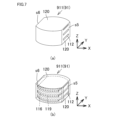
- 6 and 7 show part of the process of manufacturing a sintered body 91 which is round and wholly cylindrical. As shown in FIG. 7, the sintered body 91 has a shape in which a portion of a cylinder is cut parallel to the tangential line and two opposing side surfaces s5 and s6 are formed. ”.
- the sintered body 91 has substantially the same configuration as the sintered body 9 except for its shape. Differences will be mainly described below.
- FIG. 6(a) is a perspective view showing the appearance of the green sheet laminate 911 during the manufacturing process of the sintered body 91
- FIG. 6(b) is a schematic diagram showing the laminate structure inside the green sheet laminate 911.
- the positive electrode green sheet 112, the negative electrode green sheet 116, and the separator green sheet 120, which constitute each layer of the green sheet laminate 911 the same green sheets as those constituting the green sheet laminate 101 can be used, except that their shapes are different. can. Also, the stacking order can be the same as that of the green sheet laminate 101 .
- each of the positive electrode green sheet 112 and the negative electrode green sheet 116 included in the green sheet laminate 911 has a shape in which a part of a circle is cut parallel to the tangential line.
- the positive electrode green sheets 112 and the negative electrode green sheets 116 are alternately laminated with circular separator green sheets 120 interposed therebetween.
- the positive electrode green sheet 112 and the negative electrode green sheet 116 are arranged such that the cut portions are located on opposite sides of each other.
- the separator green sheet 120 covers the entire periphery of the laminated portion.
- FIGS. 6A and 6B show the cut points c8 and c9 are indicated by thick lines.
- FIGS. 7A and 7B show the state after cutting. 6 and 7, the cutting point c8 is a position where the positive electrode green sheet 112 is cut without overlapping with the negative electrode green sheet 116. As shown in FIG. Moreover, the cut portion c8 is parallel to the cut portion of the negative electrode green sheet 116 .
- a side surface s5 is obtained in which the positive electrode green sheet 112 and the separator green sheet 120 are exposed and the negative electrode green sheet 116 is not exposed.
- the cutting point c9 is a position that does not overlap the positive electrode green sheet 112 and where the negative electrode green sheet 116 is cut. Moreover, the cut portion c9 is parallel to the cut portion of the positive electrode green sheet 112 .
- a side surface s6 is obtained in which the negative electrode green sheet 116 and the separator green sheet 120 are exposed and the positive electrode green sheet 112 is not exposed.
- degreasing and firing are performed to obtain an integrated sintered body 91 in which an insulating ceramic portion is formed on the periphery of the laminated portion.
- a current collector is connected to each of the side surfaces s5 and s6, and assembly is performed in the same manner as in Embodiment 1, whereby a lithium secondary battery can be obtained.
- the sintered body that constitutes the electrode contained in the lithium secondary battery according to the present disclosure is, in addition to the multilayer laminate type shown in Embodiments 1 and 2, one positive electrode layer and one negative electrode layer interposed with a separator. It may be a sintered body that is laminated by FIG. 8 is a schematic diagram showing part of the manufacturing process of the sintered body 92 included in the lithium secondary battery according to the present disclosure. Referring to FIG. 8(4), sintered body 92 includes laminate 111 as a laminated portion in which one layer of positive electrode layer 12 and one layer of negative electrode layer 16 are laminated with separator 20 interposed therebetween.
- the sintered body 92 has a cylindrical shape, the negative electrode layer 16 is exposed on the upper surface of the sintered body 92 , and the positive electrode layer 12 is exposed on the lower surface of the sintered body 92 . Moreover, the entire periphery of the laminated body 111 included in the sintered body 92 is covered with the insulating layer 52 as the insulating ceramics portion. That is, the positive electrode layer or the negative electrode layer is not exposed on the outer peripheral surface of the sintered body 92 .
- a composition similar to that of the sintered body 9 can be used for the composition constituting each layer included in the sintered body 92 .
- round positive electrode green sheet 212 and negative electrode green sheet 116 are prepared.
- the positive electrode green sheet 212 and the negative electrode green sheet 116 may be composed of a single layer sheet, or may be composed of a plurality of sheets laminated and pressure-bonded so as to have a desired thickness.
- a separator green sheet 121 formed with holes 220 having diameters corresponding to the positive electrode green sheet 212 and the negative electrode green sheet 116, and a separator green sheet 120 without holes. prepare.
- the positive electrode green sheet 212 and the negative electrode green sheet 116 are arranged so as to fit in the holes 220 of the separator green sheet 121 , and the separator green sheet 120 is arranged between the positive electrode green sheet 212 and the negative electrode green sheet 116 .
- compression is performed to obtain the green sheet laminate 912 .
- the green sheet laminate 912 is cut.
- the cutting portion includes the positive electrode green sheet 212 and the negative electrode green sheet 216, and the cutting portion is adjusted so that the separator green sheet 120 is positioned on the periphery thereof, and the green sheet laminate 912 is cut into a cylindrical shape.
- An electrode can be formed by connecting current collectors to each of the negative electrode layer 16 exposed on the upper surface of the sintered body 92 and the positive electrode layer 12 exposed on the lower surface. Furthermore, it can be assembled according to a known method to obtain a lithium secondary battery.
- LCO green sheet positive electrode green sheet
- Co 3 O 4 powder manufactured by Seido Chemical Industry Co., Ltd.
- Li 2 CO 3 powder weighed so that the molar ratio of Li/Co was 1.01. (manufactured by Honjo Chemical Co., Ltd.) was mixed and then held at 780° C. for 5 hours.
- the obtained powder was pulverized with a pot mill so that the volume-based D50 was 0.4 ⁇ m to obtain a powder composed of LCO plate-like particles.
- 8 parts by weight of a binder polyvinyl butyral: product number BM-2, manufactured by Sekisui Chemical Co., Ltd.
- a plasticizer 2 parts by weight of (DOP: Di(2-ethylhexyl) phthalate, manufactured by Kurogane Kasei Co., Ltd.) and 4.5 parts by weight of a dispersant (product name: Rhodol SP-O30, manufactured by Kao Corporation) were mixed.
- An LCO slurry was prepared by stirring the obtained mixture under reduced pressure to remove air bubbles and adjusting the viscosity to 4000 cP.
- An LCO green sheet was formed by sheet-forming the prepared slurry on a PET film. The thickness of the positive electrode layer after firing was adjusted to 24 ⁇ m.
- LTO green sheet negative electrode green sheet
- LTO powder volume-based D50 particle size 0.06 ⁇ m, manufactured by Sigma-Aldrich Japan LLC
- binder polyvinyl butyral: product number BM-2, manufactured by Sekisui Chemical Co., Ltd.
- plasticizer DOP: Di (2-ethylhexyl) phthalate, manufactured by Kurogane Kasei Co., Ltd.
- a dispersant product name: Rheodol SP-O30, manufactured by Kao Corporation
- An LTO slurry was prepared by stirring the obtained negative electrode raw material mixture under reduced pressure to remove air bubbles and adjusting the viscosity to 4000 cP.
- An LTO green sheet was formed by forming the prepared slurry into a sheet on a PET film. The thickness of the negative electrode layer after firing was adjusted to 10 ⁇ m.
- a slurry was prepared by stirring the obtained raw material mixture under reduced pressure to remove air bubbles and adjusting the viscosity to 4000 cP.
- a separator green sheet was formed by forming the prepared slurry into a sheet on a PET film. The thickness of the separator positioned between the positive electrode layer and the negative electrode layer was set to 25 ⁇ m after firing. The thickness of the separator (insulating layer) located next to the positive electrode layer was set to 24 ⁇ m after firing. The thickness of the separator (insulating layer) located next to the negative electrode layer was set to 20 ⁇ m after firing.
- Sheet cutting 1 The green sheets obtained in were cut for lamination.
- the positive electrode green sheet and the negative electrode green sheet were cut into squares of 20 mm ⁇ 9.5 mm.
- the separator green sheet was cut into squares of 25 mm ⁇ 25 mm.
- the cutting position is such that, in the width direction of the laminate, the end faces of the positive electrode layer green sheet and the separator green sheet are exposed on one side, and the end faces of the negative electrode layer green sheet and the separator green sheet are exposed on the other side. disconnected.
- the whole depth direction (9.5 mm) of the positive electrode green sheet and the negative electrode green sheet is included in the laminate after cutting, and the total thickness of the insulating ceramic part is 0.5 mm. disconnected. That is, the laminate was cut so that only the separator green sheets were exposed on the front and back sides of the laminate.
- conductive carbon paste Binder (CMC: MAC350HC, manufactured by Nippon Paper Industries Co., Ltd.) is weighed to 1.2 wt% with respect to pure water, and dissolved with a stirrer to obtain a 1.2 wt% CMC solution.
- Ta A carbon dispersion (product number: BPW-229, manufactured by Nippon Graphite Co., Ltd.) and a dispersing agent solution (product number: LB-300, manufactured by Showa Denko KK) were prepared.
- the carbon dispersion, the dispersant solution, and the 1.2 wt% CMC solution were weighed so that the ratio was 0.22:0.29:1, and mixed by a rotation/revolution mixer to obtain a conductive carbon paste. was prepared.
- FIG. 9 shows a schematic perspective view of the external appearance of the lithium secondary battery.
- the electrolytic solution LiPF 6 was dissolved to a concentration of 1.5 mol/L in an organic solvent in which propylene carbonate (PC) and ⁇ -butyrolactone (GBL) were mixed at a volume ratio of 1:3. Using.
- Example 1 A lithium secondary battery was produced in the same manner as in Example 1, except for the position where the green sheet was cut and the green sheet laminate was cut.
- the positive electrode green sheet and the negative electrode green sheet were cut into squares of 20 mm ⁇ 20 mm.
- the separator green sheet was cut into squares of 25 mm ⁇ 25 mm.
- various green sheets were laminated and pressed in the same manner as in Example 1.
- the pressed laminate was placed at a position where one of the two side surfaces exposed the positive electrode layer and the separator (the negative electrode layer was not exposed) and the other side was the position where the negative electrode layer and the separator were exposed (the positive electrode layer was not exposed). disconnected.
- the front and back surfaces of the laminate were cut at positions where the positive electrode layer, the separator and the negative electrode layer were exposed.
- the size of the green sheet laminate after cutting was set to 10 mm ⁇ 10 mm as in Example 1.
- Example 2 As in Example 1, a positive electrode green sheet, a negative electrode green sheet and a separator green sheet were produced. In the green sheet cutting process, the positive electrode green sheet and the negative electrode green sheet were each punched out with a circular puncher having a diameter of 15.5 mm to obtain a circular green sheet. Further, each circular green sheet was cut linearly in parallel with the tangent line at the point at a position 2 mm from one point on the end face toward the center. Next, in the same stacking order as in Example 1, various green sheets were stacked such that the number of cells formed in the stack was 15. As shown in FIG. 6, the positive electrode green sheet and the negative electrode green sheet were arranged so that their cut end surfaces were positioned to face each other across the center of the circle.
- the green sheet laminate was pressed under the same conditions as in Example 1 to press the green sheets together.
- the pressed green sheet laminate was punched out with a hand puncher having a diameter of 16 mm.
- two points were cut along two parallel straight lines. The cutting positions were such that the positive electrode and the separator were exposed on one end face and the negative electrode layer was not exposed, and the negative electrode layer and the separator were exposed and the positive electrode layer was not exposed on the other end face.
- degreasing and firing were carried out in the same manner as in Example 1 to obtain a round multilayer laminated sintered body whose periphery was covered with a separator (insulating ceramic portion).
- An aluminum foil as a positive electrode current collector was placed on the exposed surface of the positive electrode and the separator with a conductive carbon paste interposed therebetween. Further, an aluminum foil as a negative electrode current collector was placed on the surface where the negative electrode and the separator were exposed, with a conductive carbon paste interposed therebetween.
- a lithium secondary battery was assembled in the same manner as in Example 1.
- Example 2 As in Example 1, a positive electrode green sheet, a negative electrode green sheet and a separator green sheet were produced. As in Comparative Example 1, the positive electrode green sheet and the negative electrode green sheet were cut into squares of 20 mm ⁇ 20 mm. The separator green sheet was cut into squares of 25 mm ⁇ 25 mm. After that, various green sheets were laminated and pressed in the same manner as in Example 1. Next, various green sheets were laminated in the same order and position as in Example 1 so that the number of cells formed in the laminate was 15. Subsequently, the green sheet laminate was pressed under the same conditions as in Example 1 to press the green sheets together. The pressed green sheet laminate was punched out with a hand puncher having a diameter of 16 mm.
- Example 3 A positive electrode green sheet was produced in the same manner as in Example 1, except that the thickness after firing was 100 ⁇ m. Further, a negative electrode green sheet was produced in the same manner as in Example 1, except that the thickness after firing was set to 100 ⁇ m. A separator green sheet was produced in the same manner as in Example 1. In the lamination, seven positive electrode green sheets and three negative electrode green sheets cut to 20 mm ⁇ 20 mm were separately laminated, and pressed at 100 kgf/cm 2 by CIP to crimp the green sheets together. Then, they were punched out with a round puncher having a diameter of 15.5 mm to obtain round positive electrode temporary laminates and negative electrode temporary laminates shown in FIG. 8 (1).
- the separator green sheet was also laminated and crimped in the same manner so as to have the same thickness as the positive electrode temporary laminate and the negative electrode temporary laminate, and punched with a round puncher with a diameter of 15.5 mm [Fig. 8] ( 2), a separator temporary laminate having a round hole with a diameter of 15.5 mm was obtained.
- the positive electrode temporary laminate and the negative electrode temporary laminate were inserted into round holes of the separator temporary laminate having the same thickness as the respective thicknesses, and furthermore, a stacking and pressure bonding process was performed with a separator green sheet sandwiched therebetween.
- the resulting laminate was punched into a cylindrical shape using a round puncher with a diameter of 16 mm. In this way, as shown in FIG.
- an unsintered green sheet laminate was obtained in which an insulating ceramic portion of 0.25 mm was formed on the peripheral edge of the laminated portion of 15.5 mm in diameter.
- Debinding and sintering were performed in the same manner as in Example 1 to obtain a sintered body in which one positive electrode layer, a separator, and one negative electrode layer were integrally sintered and provided with an insulating ceramic part on the periphery.
- a lithium secondary battery was produced in the same manner as in Example 1.
- Example 3 A positive electrode green sheet and a negative electrode green sheet were produced in the same manner as in Example 3.
- a separator green sheet was produced in the same manner as in Example 1. Seven positive electrode green sheets each cut to 20 mm ⁇ 20 mm, one separator green sheet, and three negative electrode green sheets were laminated in this order, and pressed by CIP at 100 kgf/cm 2 to crimp the green sheets together. This laminate was punched into a cylindrical shape using a round puncher with a diameter of 16 mm to obtain an unsintered green sheet laminate. Debinding and sintering were performed in the same manner as in Example 1 to obtain a round sintered body in which one positive electrode layer, a separator, and one negative electrode layer were integrally sintered. The positive electrode layer, the separator, and the negative electrode layer were exposed at the periphery of the sintered body.
- a lithium secondary battery was produced in the same manner as in Example 1.
- Evaluation 1 Evaluation of battery performance (0.2C discharge capacity evaluation) Using the obtained battery, the battery capacity was confirmed under an environment of 25°C. Charging was performed at a constant current of 0.2C until the voltage reached 2.7V. Discharge was performed at a constant current of 0.2C until the voltage reached 1.5V. The second cycle of charging and discharging was performed under the same conditions as the first cycle, and the discharge capacity of this second cycle was taken as the 0.2C discharge capacity.
- Example 1 and Comparative Example 1 have multi-layer rectangular electrodes including the same number of cells, and differ only in the presence or absence of an insulating ceramic part at the periphery of the laminated part.
- Example 2 and Comparative Example 2 both have multi-layer circular electrodes containing the same number of cells, and differ only in the presence or absence of the insulating ceramics portion at the periphery of the laminated portion.
- Example 3 and Comparative Example 3 comprise an electrode comprising one positive electrode layer, a separator and one negative electrode layer.
- Example 3 and Comparative Example 3 differ in the presence or absence of the insulating ceramics portion at the periphery.
- Electrode 1 Laminated body, 5 Electrode, 10 Lithium secondary battery, 12 Positive electrode layer, 16 Negative electrode layer, 14 Positive electrode current collector, 18 Negative electrode current collector, 20 Separator, 22 Electrolyte, 24 Exterior body, 24a Positive electrode can, 24b Negative electrode Can, 24c gasket, 51, 52 insulating layer, 9, 91, 92 sintered body, 101 green sheet laminate, 112 positive electrode green sheet, 116 negative electrode green sheet, 120 separator green sheet.
Landscapes
- Chemical & Material Sciences (AREA)
- Chemical Kinetics & Catalysis (AREA)
- Electrochemistry (AREA)
- General Chemical & Material Sciences (AREA)
- Engineering & Computer Science (AREA)
- Inorganic Chemistry (AREA)
- Manufacturing & Machinery (AREA)
- Materials Engineering (AREA)
- Secondary Cells (AREA)
- Battery Electrode And Active Subsutance (AREA)
Abstract
正極層と、負極層と、セパレータと、を含み、前記正極層と前記負極層とが前記セパレータを介して積層された積層部を含む焼結体を備えるリチウム二次電池であって、前記焼結体は、前記積層部の周縁のうち少なくとも一部を覆い、前記積層部の前記周縁に露出する積層構造の少なくとも一部にわたって延在する絶縁性セラミックス部を含む、リチウム二次電池である。
Description
本開示は、リチウム二次電池に関する。本出願は、2022年2月24日出願の日本国特許出願2022-027151号に基づく優先権を主張し、前記日本国特許出願に記載された全ての記載内容を援用する。
リチウム二次電池において、リチウム複合酸化物の焼結体で構成される正極層と、チタンを含有する焼結体で構成される負極層と、正極層と負極層との間に配置されるセラミックセパレータと、を備えるものが公知である。例えば特許文献1は、リチウム二次電池であって、その電極が、正極層、セラミックセパレータおよび負極層が互いに結合した一体焼結板を含むものを開示している。
特許文献2は、複数の正極層と複数の負極層とが固体電解質層を介して交互に積層された積層体を有する全固体電池を開示している。特許文献2に開示された積層体は、固体電解質層の中に緩衝層が設けられていることを特徴とする。特許文献2に開示された積層体は、積層方向からの平面視において、一対の端部のそれぞれに正極層および負極層の一方が露出し、一対の端部のそれぞれに外部端子が接続されている。
リチウム二次電池において、放電容量が大きく、自己放電が少ないものが望まれている。
そこで、放電容量が大きく、自己放電が少ないリチウム二次電池を提供することを本開示にかかる発明の目的の1つとする。
本開示に従うリチウム二次電池は、正極層と、負極層と、セパレータと、を含み、前記正極層と前記負極層とが前記セパレータを介して積層された積層部を含む焼結体を備える。前記焼結体は、前記積層部の周縁のうち少なくとも一部を覆い、前記積層部の前記周縁に露出する積層構造の少なくとも一部にわたって延在する絶縁性セラミックス部を含む。
上記リチウム二次電池によれば、放電容量が大きく、自己放電が少ないリチウム二次電池が提供される。
[実施態様の概要]
最初に本開示の実施態様を列記して説明する。本開示に従うリチウム二次電池は、正極層と、負極層と、セパレータと、を含み、前記正極層と前記負極層とが前記セパレータを介して積層された積層部を含む焼結体を備える。前記焼結体は、前記積層部の周縁のうち少なくとも一部を覆い、前記積層部の前記周縁に露出する積層構造の少なくとも一部にわたって延在する絶縁性セラミックス部を含む。
最初に本開示の実施態様を列記して説明する。本開示に従うリチウム二次電池は、正極層と、負極層と、セパレータと、を含み、前記正極層と前記負極層とが前記セパレータを介して積層された積層部を含む焼結体を備える。前記焼結体は、前記積層部の周縁のうち少なくとも一部を覆い、前記積層部の前記周縁に露出する積層構造の少なくとも一部にわたって延在する絶縁性セラミックス部を含む。
従来、リチウム複合酸化物の焼結体で構成される正極層と、チタンを含有する焼結体で構成される負極層と、正極層と負極層との間に配置されるセラミックセパレータと、を備えるリチウム二次電池が知られている。正極層、負極層のそれぞれに集電体が接続され、電極が構成される。特許文献1に開示されたリチウム二次電池では、正極側集電体が正極層の下面に、負極側集電体が正極層の上面に、それぞれ導電性カーボン層を介して接続されている。これら集電体は、正極層ないし負極層の主面を覆うように配置されている。一方、正極層、セパレータおよび負極層を含む焼結体の周縁には、正極層、セパレータおよび負極層の端面が露出している。
ところで、リチウム二次電池やそれを含む製品の保存性や耐久性を向上させるために、リチウム二次電池においても他種の電池と同様に、自己放電を低減することが望まれる。このため発明者らは、焼結体で構成される電極を含む電池において得られる高容量を維持しながらも、自己放電の少ないリチウム二次電池を得ることを目的として検討を進めた。そして、従来は積層構造が露出していた積層部の周縁を絶縁性セラミックス部で覆うことによって、従来と同様の高容量を維持しながらも自己放電を顕著に低減できることを見出した。特定の理論に拘束されるものではないが、積層部の周縁が絶縁性セラミックス部で覆われた構造とすることによって、製造工程において生じることがある積層構造の微小な変形が抑制され、正極層、セパレータ、負極層の間隔が正確に保たれることが、自己放電が抑制される一因であると考えられている。
前記リチウム二次電池において、前記絶縁性セラミックス部は、前記積層部と一体に焼結されていてもよい。積層部と絶縁性セラミックス部が一体に焼結されていることによって、絶縁性セラミックス部を設けることによる効果を確実に得ることができるとともに、電極を効率的かつ安定に製造できる。
前記リチウム二次電池において、前記絶縁性セラミックス部と前記セパレータとは同じ組成物で構成されてもよい。絶縁性セラミックス部とセパレータとを同じ組成物で構成することによって、電極を効率的に製造できる。また、焼結時における層間の剥がれが生じ難く、安定に電極を製造できる。
前記リチウム二次電池において、前記焼結体の表面は、前記絶縁性セラミックス部で覆われた面と、前記正極層が露出し、かつ前記負極層が露出しない面と、前記負極層が露出し、かつ前記正極層が露出しない面と、から構成されてもよい。この構成によれば、正極層が露出する面および負極層が露出する面のそれぞれに正極側集電体と負極側集電体のそれぞれを配置し、正極層や負極層の端面が電極の表面に露出しない構成にできる。この構造によれば、より確実に自己放電の低減を図ることができる。
前記リチウム二次電池において、前記積層部は、複数の正極層と、複数の負極層と、セパレータと、を含み、前記正極層と前記負極層とが前記セパレータを介して交互に積層されてもよい。すなわち、リチウム二次電池に含まれる焼結体は、一つの焼結体中に複数のセルが含まれる多層積層型の焼結体であってもよい。一般に、焼結体における積層数が多くなるほど各層の間隔を正確に保つことの困難性が増すところ、積層部の周縁に絶縁性セラミックス部を備えることによって、各層の間隔が正確に維持されやすくなる。このため、多層積層型の焼結体でありながらも自己放電の少ない電極を得ることができる。
前記リチウム二次電池において、正極層はリチウム複合酸化物焼結体で構成され、前記負極層はチタン含有焼結体で構成されてもよい。リチウム複合酸化物焼結体で構成される正極層およびチタン含有焼結体で構成される負極層は公知の構成であり、上記の構成と組み合わせることによってより安定に、自己放電の抑制されたリチウム二次電池が得られる。
[実施態様の具体例]
次に、本開示に従うリチウム二次電池の具体的な実施態様を、図面を参照しつつ説明する。以下の図面において同一または相当する部分には同一の参照符号を付し、その説明は繰り返さない。また、各図面において、同種の部材は同種のハッチングで示すとともに、繰り返し構造における符号の表示は一部省略している。
次に、本開示に従うリチウム二次電池の具体的な実施態様を、図面を参照しつつ説明する。以下の図面において同一または相当する部分には同一の参照符号を付し、その説明は繰り返さない。また、各図面において、同種の部材は同種のハッチングで示すとともに、繰り返し構造における符号の表示は一部省略している。
(実施の形態1)
(リチウム二次電池)
まず、本開示に従うリチウム二次電池の概要を説明する。図1は、本開示にかかる実施の形態の一例であるリチウム二次電池10の構造を示す概略断面模式図である。図2は、リチウム二次電池10に含まれる焼結体9を取り出して示す概略斜視図である。なお、図1、図2を参照して、X軸方向を積層体1ないし焼結体9の幅方向、Y軸方向を積層体1ないし焼結体9の奥行方向、Z軸方向を積層体1ないし焼結体9の積層方向または厚み方向と称する。本明細書では、積層体1において積層方向の最上層の表面を上面、積層方向の最下層の表面を下面、積層されたすべての層が露出する面を正面および背面と称する。正面および背面は、XZ平面に平行な面である。また、積層体1において、積層構造が露出する面であって、正面および背面の間に延在し、奥行き方向に沿って延びる面を側面と称する。側面は、YZ平面に平行な面である。上面および下面を除く表面、つまり、側面に加えて正面および背面についても、側面と称することもある。なお、上面、下面、側面等は本明細書における説明の便宜のために用いる相対的な呼称であり、リチウム二次電池における配置方向や使用方向はこれらの方向に制限されないことは当然である。
図1を参照して、リチウム二次電池10は、外装体24の内部に、電極5が収容されている。電極5は、焼結体9と、焼結体9の両側面にそれぞれ取り付けられた正極集電体14および負極集電体18を含む。焼結体9は、積層部としての積層体1と、積層体1の周縁に延在する絶縁性セラミックス部としての絶縁層51(図2)とを含む。積層体1は、複数の正極層12と複数の負極層16とセパレータ20とが積層されてなる。積層体1および絶縁層51は、全体として1つの一体焼結体である焼結体9を構成している。
積層体1において、正極層12および負極層16は、積層方向において交互に積み重ねられている。セパレータ20は、正極層12と負極層16との間に介在する。セパレータ20によって、正極層12と負極層16とは互いに離隔されている。正極層12は、例えばコバルト酸リチウムを含む焼結体で構成される。負極層16は、例えばチタン含有焼結体で構成される。セパレータ20は、セラミック製である。
外装体24は内部に密閉空間が形成されている。この密閉空間内に、電極5および電解液22が収容される。リチウム二次電池10は、外装体24の内部に電解液22が封入されている。正極層12、負極層16およびセパレータ20にも、電解液22が含浸されている。
なお、外装体24は、リチウム二次電池10のタイプに応じて適宜選択すればよい。例えば、リチウム二次電池10が図1に示されるようにコイン形電池の形態である場合、外装体24は、典型的には正極缶24a、負極缶24bおよびガスケット24cを備え、正極缶24aおよび負極缶24bがガスケット24cを介してかしめられて密閉空間を形成している。正極缶24aおよび負極缶24bは、ステンレス鋼等の金属製であってよく、これらに限定されない。ガスケット24cは、ポリプロピレン、ポリテトラフルオロエチレン、PFA樹脂等の絶縁樹脂製の環状部材であってよく、特に限定されない。
図1に示されるリチウム二次電池10はコイン形電池の形態であるが、本開示に従うリチウム二次電池の形態は、コイン形電池に限定されない。例えば、チップ型二次電池、パウチ型二次電池を含む薄型二次電池等の他の形態であってもよい。リチウム二次電池がカードに内蔵可能なチップ型電池である場合、外装体は樹脂基材であり、電池要素(すなわち電極5および電解液22)は、樹脂基材内に埋設されるのが好ましい。例えば、リチウム二次電池がパウチ型二次電池である場合、電池要素は1対の樹脂フィルムに挟み込まれていてもよい。一対の樹脂フィルムは、互いに接着剤で貼り合わされたものであってよい。また、一対の樹脂フィルムは、加熱プレスで樹脂フィルム同士が熱融着されていてもよい。さらに、セパレータとして、固体電解質から構成されるセパレータを採用し、電解液を含まない構成であってもよい。
図1を参照して、リチウム二次電池10の電極5は、焼結体9の側面から下面にわたって焼結体9に接続する正極集電体14を備える。また、リチウム二次電池10は、焼結体9の側面から上面にわたって焼結体9に接続する負極集電体18を備える。正極集電体14および負極集電体18は、例えば銅箔やアルミニウム箔等の金属箔であってよい。正極集電体14および負極集電体18のそれぞれと焼結体9との間には、接触抵抗低減の観点から、カーボン層(不図示)が設けられるのが好ましい。カーボン層は、導電性カーボンで構成されるのが好ましい。カーボン層は、例えば、集電体として用いる金属箔の表面に導電性カーボンペーストを塗布することによって形成できる。
(焼結体)
本開示にかかるリチウム二次電池に含まれる焼結体について説明する。図2は、本開示に従うリチウム二次電池に含まれる焼結体9を示す概略斜視図である。図2(a)は外観を示し、図2(b)は焼結体9に含まれる層の構成を、内部を含めて示す模式図である。
本開示にかかるリチウム二次電池に含まれる焼結体について説明する。図2は、本開示に従うリチウム二次電池に含まれる焼結体9を示す概略斜視図である。図2(a)は外観を示し、図2(b)は焼結体9に含まれる層の構成を、内部を含めて示す模式図である。
図2(b)を参照して、焼結体9は、複数の正極層12と、複数の負極層16と、セパレータ20とが、Z軸方向(厚み方向)に積み重ねられてなる積層部としての積層体1を含む。図2(a)、(b)を参照して、積層体1の周縁のうち第1の側面s1は、正極層12とセパレータ20とが露出し、かつ負極層16は露出しない面である。積層体1の周縁のうち第2の側面s2は、負極層16とセパレータ20とが露出し、かつ正極層12は露出しない面である。焼結体9において、積層体1の第1の側面s1および第2の側面s2は外部に露出し、焼結体9の表面を構成している。
一方、図2(b)を参照して、積層体1の周縁のうち、第3の側面s3および第4の側面s4は、正極層、負極層およびセパレータの端面が表れる面である。すなわち、第3の側面s3および第4の側面s4には、正極層、負極層およびセパレータを含む積層構造が現れている。さらに、第3の側面s3および第4の側面s4は、絶縁性セラミックス部としての絶縁層51によって覆われている。すなわち、第3の側面s3および第4の側面s4は、焼結体9においては絶縁層51に覆われているため外部には露出しない面である。
なお、本明細書において積層部の周縁とは、積層体1の表面のうち、積層方向における上面および下面を除き、外周に位置する面を意味している。
なお、本明細書において積層部の周縁とは、積層体1の表面のうち、積層方向における上面および下面を除き、外周に位置する面を意味している。
図2に示された例では、焼結体9は直方体の形状(四角型)であるが、焼結体の外形はこれに制限されない。例えば、側面を有する円柱形(丸型)であってもよく、その他の多角柱形状であってもよい。また、絶縁層51は、第3の側面s3および第4の側面s4の全面を覆っているが、第3の側面s3および第4の側面s4の一部のみを覆う態様でもよい。
(積層部)
本開示に従うリチウム二次電池に含まれる積層部について説明する。図3は、本開示に従うリチウム二次電池に含まれる積層部としての積層体1を示す概略断面斜視図である。図3を参照して、積層体1は多数の層が積層された積層体である。積層体1は幅W、奥行きD、厚みTでその外形が定義される直方体形状である。なお、ここでいう直方体とは、数学的に正確な意味での直方体のみを意味するものではなく、設計および製造上の理由から直方体に類似する形状を有する三次元構造物も含む。
本開示に従うリチウム二次電池に含まれる積層部について説明する。図3は、本開示に従うリチウム二次電池に含まれる積層部としての積層体1を示す概略断面斜視図である。図3を参照して、積層体1は多数の層が積層された積層体である。積層体1は幅W、奥行きD、厚みTでその外形が定義される直方体形状である。なお、ここでいう直方体とは、数学的に正確な意味での直方体のみを意味するものではなく、設計および製造上の理由から直方体に類似する形状を有する三次元構造物も含む。
図3を参照して、積層体1の上面および下面はいずれもセパレータ20が露出している。積層体1において、セパレータ20を介して対向する正極層12と負極層16とが、1つのセルを形成する。図3の積層体1では5つのセルが形成されている。本開示にかかるリチウム二次電池に含まれる積層体におけるセルの数は、発明の効果を有する限り制限されないが、例えば3~200のセルが含まれる積層体であってよい。
積層体1は、複数の正極層12と複数の負極層16とが交互に積層されている。負極層16は、その主面の一方、あるいは厚み方向の内部に、集電体層19を含む。積層体1を構成する正極層12、負極層16は、それぞれ四辺形の板状である。正極層12および負極層16の幅はいずれも、積層体1の幅Wよりも小さい。すなわち、正極層12、負極層16が積層体1の幅Wの全域にわたって存在することはない。正極層12および負極層16は幅方向に互いにずれた位置に配置されており、正極層12および負極層16のそれぞれは、積層体1において対向する第1の側面s1及び第2の側面s2のうちの一方のみに露出している。具体的に、複数の正極層12はいずれも、積層体1の第1の側面s1に露出し、第2の側面s2には露出していない。正極層12は、側面s1から積層体1の幅方向の中途まで延在し、内端面12eが幅方向の末端である。また、複数の負極層16はいずれも、積層体1の第2の側面s2に露出し、第1の側面s1には露出していない。負極層16は、側面s2から積層体1の幅方向の中途まで延在し、内端面16eが幅方向の末端である。
正極層12と負極層16との間にセパレータ20が介在している。セパレータ20は、第1領域21と、第2領域22と、第3領域23とを含む。第1領域は、積層体1の幅Wの全体にわたって延在し、積層体1の厚み方向において正極層12と負極層16との間に介在する。第2領域22は、正極層12とX軸方向に並び、正極層12の内端面12eと側面s2との間に延在する。第2領域22は、正極層12と側面s2の間を絶縁する絶縁層として機能する。第3領域23は、負極層16とX軸方向に並び、負極層16の内端面16eと側面s1との間に延在する。第3領域23は、負極層16と側面s1の間を絶縁する絶縁層として機能する。なお、第1領域21、第2領域22、第3領域23は境界なく一連に連続している。第1領域21、第2領域22および第3領域23は、説明の便宜のために区画された領域であり、セパレータ20は全体が連続する一体の構造体であることが好ましい。
次に、焼結体9に含まれる各層の構成およびリチウム二次電池10に含まれる電解液22について説明する。
(正極層)
正極層12は、コバルト酸リチウムを含む焼結体で構成される。正極層12はバインダーや導電助剤を含まないものとできる。コバルト酸リチウムとして、具体的には例えば、LiCoO2(以下、LCOと略称することがある)が挙げられる。板状に形成されるLCO焼結体としては、例えば特許第5587052号公報、国際公開第2017/146088号に開示されるものを用いることができる。正極層12は、コバルト酸リチウムで構成される複数の一次粒子を含み、複数の一次粒子が正極層の層面に対して0°超30°以下の平均配向角度で配向している、配向正極層であることが好ましい。このような配向正極層の構造、組成、特定方法は、例えば特許文献1(国際公開第2019/221144号公報)に開示されるものが挙げられる。
正極層12において一次粒子を構成するコバルト酸リチウムとして、LCOのほかに、例えば、LixNiCoO2(ニッケル・コバルト酸リチウム)、LixCoNiMnO2(コバルト・ニッケル・マンガン酸リチウム)、LixCoMnO2(コバルト・マンガン酸リチウム)等が挙げられる。また、コバルト酸リチウムとともに、その他のリチウム複合酸化物を含んでもよい。リチウム複合酸化物としては例えば、LixMO2(式中、0.05<x<1.10であり、Mは少なくとも1種類の遷移金属であり、Mは典型的にはCo、NiおよびMnの1種以上を含む)で表される酸化物が挙げられる。
正極層12がLCOを含む板状の焼結体で構成される場合、正極層を構成する元素のうち遷移金属元素はCoである。また、正極層12がLixNiCoO2(ニッケル・コバルト酸リチウム)を含む焼結体で構成される場合、正極層を構成する元素のうち遷移金属元素はNiおよびCoである。また、正極層12がLixCoNiMnO2(コバルト・ニッケル・マンガン酸リチウム)を含む焼結体で構成される場合、正極層を構成する元素のうち遷移金属元素はNi、CoおよびMnである。また、コバルト酸リチウム系以外の正極でも同様である。例えば、正極がLiFePO4(リン酸鉄リチウム)で構成される場合、正極層を構成する元素のうち遷移金属元素はFeである。また、正極層を構成する遷移金属元素は、V(バナジウム)等の遷移金属元素であってもよい。
正極層12を構成する複数の一次粒子の平均粒径は、5μm以上であることが好ましい。具体的には、平均配向角度の算出に用いる一次粒子の平均粒径が、5μm以上であることが好ましく、より好ましくは7μm以上、さらに好ましくは12μm以上である。
正極層12は気孔を含んでいてもよい。焼結体が気孔、特に開気孔を含むことで、正極層として電池に組み込まれた場合に、電解液を焼結体の内部に浸透させることができ、その結果、リチウムイオン伝導性を向上することができる。正極層12における気孔率は、20~60%であるのが好ましく、より好ましくは25~55%、さらに好ましくは30~50%、特に好ましくは30~45%である。焼結体の気孔率は、公知の方法に従って測定できる。
正極層12の平均気孔径は0.1~10.0μmであるのが好ましく、より好ましくは0.2~5.0μm、さらに好ましくは0.25~3.0μmである。上記範囲内であると、大きな気孔の局所における応力集中の発生を抑制して、焼結体内における応力が均一に開放されやすくなる。また、気孔による電解液の内部浸透によるリチウムイオン伝導性の向上をより効果的に実現することができる。
積層体1における正極層12の厚みは特に制限されないが、例えば2~200μmであるのが好ましく、より好ましくは5~120μm、さらに好ましくは10~80μmである。このような範囲内であると、電子抵抗を抑えるとともに、電解液に含まれるLiイオンの移動抵抗も抑えられ、電池抵抗を小さくできるいうメリットがある。
(セパレータ)
セパレータ20は、セラミック製の微多孔膜で構成される。セパレータ20は、マグネシア(MgO)を含む。具体的には例えば、マグネシア(MgO)およびガラスで構成されるものとできる。セパレータ20において、MgOおよびガラスは、焼結によって互いに結合された粒子形態で存在する。セパレータ20に含まれるセラミックは、MgOおよびガラスのほか、Al2O3、ZrO2、SiC、Si3N4、AlN等を含んでもよい。
セパレータ20は、セラミック製の微多孔膜で構成される。セパレータ20は、マグネシア(MgO)を含む。具体的には例えば、マグネシア(MgO)およびガラスで構成されるものとできる。セパレータ20において、MgOおよびガラスは、焼結によって互いに結合された粒子形態で存在する。セパレータ20に含まれるセラミックは、MgOおよびガラスのほか、Al2O3、ZrO2、SiC、Si3N4、AlN等を含んでもよい。
セパレータ20に含まれるガラスは、SiO2を好ましくは25重量%以上、より好ましくは30~95重量%、さらに好ましくは40~90重量%、特に好ましくは50~80重量%含む。セパレータ20におけるガラスの含有量は、セパレータ20の全体重量に対して、好ましくは3~70重量%であり、より好ましくは5~50重量%、さらに好ましくは10~40重量%、特に好ましくは15~30重量%である。この範囲内であるとき、高い歩留まりと優れた充放電サイクル特性との両立を効果的に実現できる。セパレータ20へのガラス成分の添加は、セパレータの原料粉末にガラスフリットを添加することにより行われるのが好ましい。ガラスフリットは、SiO2以外の成分として、Al2O3、B2O3およびBaOのいずれか一つ以上を含むのが好ましい。
積層体1におけるセパレータ20の厚みは特に制限されないが、例えば、セパレータ20の第1領域21(正極層12と負極層16との間の領域)の厚みは、5~60μmであるのが好ましく、より好ましくは10~30μmである。セパレータ20の第2領域22および第3領域23はそれぞれ、正極層12および負極層16と同等の厚みとできる。セパレータ20の気孔率も特に制限されないが、例えば30~70%程度とすることができ、好ましくは40~60%程度である。
(負極層)
負極層16は、例えば、チタン含有組成物を含む板状の焼結体で構成される。負極層16は、バインダーや導電助剤を含まないものとできる。チタン含有焼結体は、チタン酸リチウムLi4Ti5O12(以下、LTO)またはニオブチタン複合酸化物Nb2TiO7を含むのが好ましく、より好ましくはLTOを含む。なお、LTOは典型的にはスピネル型構造を有するものとして知られているが、充放電時には他の構造も採りうる。例えば、LTOは充放電時にLi4Ti5O12(スピネル構造)とLi7Ti5O12(岩塩構造)の二相共存にて反応が進行する。したがって、LTOはスピネル構造に限定されるものではない。LTOはその一部が他の元素で置換されてもよい。他の元素の例としては、Nb、Ta、W、Al、Mg等が挙げられる。LTO焼結体は、例えば、特開2015-185337号公報に記載される方法に従って製造することができる。
負極層16は、例えば、チタン含有組成物を含む板状の焼結体で構成される。負極層16は、バインダーや導電助剤を含まないものとできる。チタン含有焼結体は、チタン酸リチウムLi4Ti5O12(以下、LTO)またはニオブチタン複合酸化物Nb2TiO7を含むのが好ましく、より好ましくはLTOを含む。なお、LTOは典型的にはスピネル型構造を有するものとして知られているが、充放電時には他の構造も採りうる。例えば、LTOは充放電時にLi4Ti5O12(スピネル構造)とLi7Ti5O12(岩塩構造)の二相共存にて反応が進行する。したがって、LTOはスピネル構造に限定されるものではない。LTOはその一部が他の元素で置換されてもよい。他の元素の例としては、Nb、Ta、W、Al、Mg等が挙げられる。LTO焼結体は、例えば、特開2015-185337号公報に記載される方法に従って製造することができる。
負極層16がLTOを含む焼結体で構成される場合、負極層を構成する元素のうち遷移金属元素はTiである。また、負極層16がNb2TiO7を含む焼結体で構成される場合、負極層を構成する元素のうち遷移金属元素はNbおよびTiである。
負極層16は、多数の一次粒子が結合した構造を有している。これらの一次粒子がLTOまたはNb2TiO7で構成されていることが好ましい。負極層16は、正極層12およびセパレータ20とともに一体焼結体として構成されていてもよい。また、負極層16は、正極層12およびセパレータ20の一体焼結体とは別の焼結体として構成された後に組み合わせられていてもよい。
積層体1における負極層16の厚みは特に制限されないが、例えば1~150μmであるのが好ましく、より好ましくは2~120μmであり、さらに好ましくは5~80μmである。負極層16を構成する複数の一次粒子の平均粒径である一次粒径は、1.2μm以下が好ましく、より好ましくは0.02~1.2μm、さらに好ましくは0.05~0.7μmである。
負極層16は気孔を含んでいるのが好ましい。気孔、特に開気孔を含むことで、負極層として電池に組み込まれた場合に電解液を内部に浸透させることができ、その結果、リチウムイオン伝導性を向上することができる。負極層16の気孔率は、20~60%が好ましく、より好ましくは30~55%、さらに好ましくは35~50%である。負極層16の平均気孔径は0.08~5.0μmであるのが好ましく、より好ましくは0.1~3.0μm、さらに好ましく0.12~1.5μmである。
積層体1において、負極層16は、集電体層19を含んでいてもよい。集電体層19は、負極層16における厚み方向の内部に設けられていてもよい。また、負極層16の主面の一方に露出して形成されていてもよい。集電体層19は、導電性に優れる材料で構成することができる。集電体層19は、例えば、金、銀、プラチナ、パラジウム、アルミニウム、銅、ニッケル等で構成されていてよい。集電体層19を含むことによって、積層体の、特に負極における内部抵抗を低減できる。
(絶縁性セラミックス部)
焼結体9に含まれる絶縁層51は、絶縁性のセラミックで構成される。具体的には、セパレータとして用いられるものと同様のセラミックを用いることができる。絶縁層51の厚みw2(図2(b))は特に制限されないが、例えば100μm~1000μmであるのが好ましく、より好ましくは200μm~500μmである。なお、絶縁層51とセパレータ20が同じ組成物で構成される場合等では、焼結過程で絶縁層とセパレータが一体化し、焼結体9においては絶縁層51とセパレータ20とが境界のない一体の領域になっていてもよい。
焼結体9に含まれる絶縁層51は、絶縁性のセラミックで構成される。具体的には、セパレータとして用いられるものと同様のセラミックを用いることができる。絶縁層51の厚みw2(図2(b))は特に制限されないが、例えば100μm~1000μmであるのが好ましく、より好ましくは200μm~500μmである。なお、絶縁層51とセパレータ20が同じ組成物で構成される場合等では、焼結過程で絶縁層とセパレータが一体化し、焼結体9においては絶縁層51とセパレータ20とが境界のない一体の領域になっていてもよい。
絶縁層51は、積層体1の第3の側面s3および第4の側面s4の両方をそれぞれ覆うように設けられることが好ましいが、第3の側面s3および第4の側面s4のうちいずれか一方を覆う態様であってもよい。また、第3の側面s3、第4の側面s4の全面を覆うことが好ましいが、一部のみを覆う態様であってもよい。絶縁層51は、第3の側面s3および第4の側面s4の積層方向の少なくとも一部にわたって、積層を構成する複数の層のうち少なくとも一部の層を覆うように延在する。
絶縁層51が存在することによる効果は、特に理論に拘束されるものではないが、次のように考えられている。すなわち、正極層とセパレータと負極層とを含む積層体を焼結して電極を製造しようとするとき、積層構造が露出する側面(第3の側面s3あるいは第4の側面s4)において、露出する正極層12や負極層16の端面に、わずかな変形が生じることがある。変形が生じる結果、正極層と負極層の間がセパレータによって正しく隔離されなくなることがあり、これが自己放電の一因になりうると考えられた。これに対して、積層構造が露出する領域の外縁にさらに絶縁層51を設けると、製造工程のうちグリーンシート積層体を切断して所望の形状の積層体を得る段階で、正極層と負極層が重畳された積層構造部分は切断せず、絶縁層51の部分を切断して積層体を得ることができる。絶縁層51を切断箇所とすることで、切断時のストレスが積層構造に影響しにくくなる。このことによって、第3の側面s3あるいは第4の側面s4に露出する正極層12の端面および負極層16の端面の変形が抑制され、結果として自己放電の発生が抑制されると考えられている。
(電解液)
図1を参照して、リチウム二次電池10は電解液22を含んでよい。電解液22は、特に限定されず、リチウム二次電池における電解液として公知の電解液が用いられうる。例えば、溶媒として、エチレンカーボネート(EC)、メチルエチルカーボネート(MEC)、ジエチルカーボネート(DEC)、エチルメチルカーボネート(EMC)、プロピレンカーボネート(PC)およびγ-ブチロラクトン(GBL)から選択される1種または2種以上の組み合わせを用いることができる。溶媒に溶解される電解質として、例えば、六フッ化リン酸リチウム(LiPF6)、ホウフッ化リチウム(LiBF4)等のリチウム塩化合物が用いられ得る。電解液22は添加剤としてビニレンカーボネート(VC)、フルオロエチレンカーボネート(FEC)、ビニルエチレンカーボネート(VEC)、およびリチウムジフルオロ(オキサラト)ボレート(LiDFOB)から選択される少なくとも1種をさらに含むものであってもよい。
図1を参照して、リチウム二次電池10は電解液22を含んでよい。電解液22は、特に限定されず、リチウム二次電池における電解液として公知の電解液が用いられうる。例えば、溶媒として、エチレンカーボネート(EC)、メチルエチルカーボネート(MEC)、ジエチルカーボネート(DEC)、エチルメチルカーボネート(EMC)、プロピレンカーボネート(PC)およびγ-ブチロラクトン(GBL)から選択される1種または2種以上の組み合わせを用いることができる。溶媒に溶解される電解質として、例えば、六フッ化リン酸リチウム(LiPF6)、ホウフッ化リチウム(LiBF4)等のリチウム塩化合物が用いられ得る。電解液22は添加剤としてビニレンカーボネート(VC)、フルオロエチレンカーボネート(FEC)、ビニルエチレンカーボネート(VEC)、およびリチウムジフルオロ(オキサラト)ボレート(LiDFOB)から選択される少なくとも1種をさらに含むものであってもよい。
電解液22における電解質の濃度は、0.5~2mol/Lであるのが好ましく、より好ましくは0.6~1.9mol/L、さらに好ましくは0.7~1.7mol/L、特に好ましくは0.8~1.5mol/Lである。
また、電解質として、電解液22以外に、固体電解質やポリマー電解質を用いることができる。その場合には、電解液22の場合と同様、少なくともセパレータ20の気孔内部に電解質が含浸されていることが好ましい。含浸方法は特に限定されないが、例として、電解質を溶融してセパレータ20の気孔内に浸入させる方法、電解質の圧粉体をセパレータ20に押し当てる方法等が挙げられる。
(製造方法)
本開示に従うリチウム二次電池に含まれる焼結体の製造方法の概略を説明する。図4は、焼結体の製造工程のうち、積層体を構成するための各シートを準備し、積み重ねて圧着する工程を模式的に示す。
本開示に従うリチウム二次電池に含まれる焼結体の製造方法の概略を説明する。図4は、焼結体の製造工程のうち、積層体を構成するための各シートを準備し、積み重ねて圧着する工程を模式的に示す。
図4(1)を参照して、積層体を構成する材料となる正極グリーンシート112、負極グリーンシート116、セパレータグリーンシート120が、それぞれ別に準備される。典型的には、まず各層を構成する原料を含有するスラリーを調製し、次いで調製したスラリーを樹脂フィルム上にシート状に形成することで、グリーンシートを準備できる。負極グリーンシート116については、主面の一方に集電体層119が形成されていてもよい。図4(2)を参照して、所定の幅に切断した各シートを、所定の層構成となるように順に積み重ねる。なお、図4の例では層構成を簡潔に示しているが、負極グリーンシート116、セパレータグリーンシート120、正極グリーンシート112およびセパレータグリーンシート120を含むユニットUを繰り返して積層し、さらに多層の積層体としてもよい。
図4(1)を参照して、積み重ねの際、各グリーンシートは、厚み方向に1枚単独で用いてもよいし、厚み方向に2枚以上同種のシートを連続して重ねる形態であってもよい。例えば、負極層16を構成するために、片面に集電体層119を有する負極グリーンシート116を2枚重ねてもよい。集電体層119を有する負極グリーンシート116を2枚重ねる場合には、集電体層119同士が接するように重ねることが好ましい。厚み方向に同種のシートを2枚以上重ねる場合、重ねたシートは焼結段階で一体化するため、焼結体においては一層となる。図4(2)を参照して、積層の際には、正極グリーンシート112と負極グリーンシート116とを互いに幅方向(X軸方向)にずらして配置する。このように配置することによって、焼結体9(図2)における一対の側面のうち、一方の側面には正極層12が露出するとともに負極層16が露出せず、他方の側面には負極層16が露出するとともに正極層12が露出しない構成を得ることができる。
図4(3)を参照して、グリーンシート積層体101を加圧し、層同士を圧着させる。具体的には、プレスによって、グリーンシート積層体101に含まれるグリーンシート同士を圧着させることができる。グリーンシート積層体101を厚み方向(Z軸方向)にプレスすることが好ましい。プレスの方法は例えば、冷間等方圧加圧(CIP)、温水等方圧加圧(WIP)、静水圧プレス等によることができ、特に制限されない。プレスは、加熱しながら行ってもよい。
続いて、グリーンシート積層体101を切断する。図5は、各層が四辺形に形成され、全体が直方体である四角型の焼結体を製造する場合の工程の一部を示す。図5(1)では、切断箇所c1~c4を太線で示している。図5(1)を参照して、まず所定の幅となるように、切断箇所c1、c2においてグリーンシート積層体101の両側面を切断する。切断箇所c2は、正極グリーンシート112を切断し、かつ負極グリーンシート116を切断しない位置である。切断箇所c1は、負極グリーンシート116を切断し、かつ正極グリーンシート112を切断しない位置である。例えば、正極グリーンシート112ないし負極グリーンシート116の末端から側面(切断箇所c1,c2)までの距離w1(図3)が0.5mmとなるよう切断できる。続いて、所定の奥行きを有する積層体が得られるように、切断箇所c3、c4において、グリーンシート積層体101の正面と背面を切断する。このとき、正極グリーンシート112および負極グリーンシート116の奥行方向の全域を含み、かつ、その外縁にセパレータグリーンシート120が延在するよう切断する。すなわち、切断箇所c3、c4は、セパレータグリーンシート120のみを切断し、正極グリーンシート112および負極グリーンシート116を切断しない位置である。
次いで、脱脂および焼成を行い、積層体の周縁に絶縁性セラミックス部を有する一体の焼結体9(図5(2))が得られる。脱脂および焼成は、公知の条件および方法で実施できる。得られた一体焼結体における各層の厚みや幅は、例えば、積層一体焼結体をセクロスセクションポリッシャにより研磨し、得られた断面をSEM観察することによって確認できる。
続いて、焼結体の両側面に集電体を取り付ける。図1を参照して、焼結体9の第1の側面s1に正極集電体14を、第2の側面s2に負極集電体18を、それぞれ取り付ける。正極集電体14、負極集電体18としては、導電性の材料を用いることができ、例えば、アルミニウム箔や銅箔等を用いればよい。正極集電体14は、第1の側面s1の全体を覆うように取り付けられ、さらに、焼結体9の下面に延在するよう構成されうる。負極集電体18は、第2の側面s2の全体を覆うように取り付けられ、さらに、焼結体9の上面に延在するよう構成されうる。焼結体9と正極集電体14との間、焼結体9と負極集電体18の間は、導電性接着剤を用いて接着することができる。導電性接着剤としては例えば、導電性カーボンペーストを用いることができる。導電性接着剤層の厚みは、接着剤層としての効果を発揮し、発明の効果を妨げない限り特に制限されないが、例えば1~500μm程度とできる。
上記の製造方法で得られた電極を公知の方法および条件に従って外装体の内部に収容し、電解液を封入して、リチウム二次電池を得ることができる。
(実施の形態2)
本開示に従うリチウム二次電池に含まれる電極を構成する焼結体は、実施の形態1に示した四角型のほか、例えば丸型であってもよい。図6、図7は、丸型に形成され、全体が円柱体である焼結体91を製造する工程の一部を示す。なお、焼結体91は、図7に示されるとおり、円柱の一部が接線に平行に切除され、対向する2つの側面s5、s6が形成された形状であるが、この形状を「丸型」と称する。焼結体91は、形状において焼結体9と異なる以外は、おおむね同じ構成である。以下では異なる点を主として説明する。
本開示に従うリチウム二次電池に含まれる電極を構成する焼結体は、実施の形態1に示した四角型のほか、例えば丸型であってもよい。図6、図7は、丸型に形成され、全体が円柱体である焼結体91を製造する工程の一部を示す。なお、焼結体91は、図7に示されるとおり、円柱の一部が接線に平行に切除され、対向する2つの側面s5、s6が形成された形状であるが、この形状を「丸型」と称する。焼結体91は、形状において焼結体9と異なる以外は、おおむね同じ構成である。以下では異なる点を主として説明する。
図6(a)は焼結体91の製造過程におけるグリーンシート積層体911の外観を示す斜視図であり、図6(b)はグリーンシート積層体911の内部の積層構造を示す模式図である。グリーンシート積層体911の各層を構成する正極グリーンシート112、負極グリーンシート116、セパレータグリーンシート120としては、形状が異なる以外はグリーンシート積層体101を構成する各種グリーンシートと同じものを用いることができる。また、積層順もグリーンシート積層体101と同様にできる。
図6(b)を参照して、グリーンシート積層体911に含まれる正極グリーンシート112、負極グリーンシート116はそれぞれ、円の一部が接線に平行に切除された形状である。この正極グリーンシート112、負極グリーンシート116が、円形のセパレータグリーンシート120を介して交互に積層されている。また、正極グリーンシート112と負極グリーンシート116とは、切除箇所が互いに逆側に位置するよう配置されている。さらに、積層部分の周縁全体をセパレータグリーンシート120が覆っている。
グリーンシート積層体911を積層および圧着した後、グリーンシート積層体911を切断する。図6(a)、(b)において、切断箇所c8、c9を太線で示している。図7(a)、(b)は切断後の状態を示している。図6、図7を参照して、切断箇所c8は、負極グリーンシート116と重複せず、かつ正極グリーンシート112を切断する位置である。また、切断箇所c8は負極グリーンシート116の切除部と平行である。この位置でグリーンシート積層体911を切断することによって、断面に正極グリーンシート112およびセパレータグリーンシート120が露出し、かつ負極グリーンシート116が露出しない側面s5が得られる。切断箇所c9は、正極グリーンシート112と重複せず、かつ負極グリーンシート116を切断する位置である。また、切断箇所c9は正極グリーンシート112の切除部と平行である。この位置でグリーンシート積層体911を切断することによって、断面に負極グリーンシート116およびセパレータグリーンシート120が露出し、かつ正極グリーンシート112が露出しない側面s6が得られる。次いで、脱脂および焼成を行い、積層部の周縁に絶縁性セラミックス部が形成された一体の焼結体91が得られる。側面s5、s6のそれぞれに集電体を接続し、実施の形態1と同様に組み立てを行い、リチウム二次電池を得ることができる。
(実施の形態3)
本開示に従うリチウム二次電池に含まれる電極を構成する焼結体は、実施の形態1、2に示した多層積層型のほか、1層の正極層と1層の負極層とがセパレータを介して積層された焼結体であってもよい。図8は、本開示に従うリチウム二次電池に含まれる焼結体92の作製工程の一部を示す模式図である。図8(4)を参照して、焼結体92は、1層の正極層12と、1層の負極層16とがセパレータ20を介して積層された積層部としての積層体111を含む。焼結体92は円柱形であり、焼結体92の上面は負極層16が露出し、焼結体92の下面には正極層12が露出している。また、焼結体92に含まれる積層体111の周縁の全体が、絶縁性セラミックス部としての絶縁層52で覆われている。すなわち、焼結体92の外周面には正極層あるいは負極層が露出していない。焼結体92に含まれる各層を構成する組成物は、焼結体9と同様のものを用いることができる。
本開示に従うリチウム二次電池に含まれる電極を構成する焼結体は、実施の形態1、2に示した多層積層型のほか、1層の正極層と1層の負極層とがセパレータを介して積層された焼結体であってもよい。図8は、本開示に従うリチウム二次電池に含まれる焼結体92の作製工程の一部を示す模式図である。図8(4)を参照して、焼結体92は、1層の正極層12と、1層の負極層16とがセパレータ20を介して積層された積層部としての積層体111を含む。焼結体92は円柱形であり、焼結体92の上面は負極層16が露出し、焼結体92の下面には正極層12が露出している。また、焼結体92に含まれる積層体111の周縁の全体が、絶縁性セラミックス部としての絶縁層52で覆われている。すなわち、焼結体92の外周面には正極層あるいは負極層が露出していない。焼結体92に含まれる各層を構成する組成物は、焼結体9と同様のものを用いることができる。
図8を参照して、焼結体92の製造方法の一例を説明する。図8(1)を参照して、丸型の正極グリーンシート212、負極グリーンシート116を準備する。正極グリーンシート212、負極グリーンシート116は、1層のシートからなってもよく、所望の厚みになるように複数のシートが積層および圧着されてなるものでもよい。次いで、図8(2)、(3)を参照して、正極グリーンシート212、負極グリーンシート116に対応する径の穴220が形成されたセパレータグリーンシート121と、穴の無いセパレータグリーンシート120とを準備する。正極グリーンシート212、負極グリーンシート116がそれぞれセパレータグリーンシート121の穴220に収まるように配置し、さらに、正極グリーンシート212、負極グリーンシート116の間にセパレータグリーンシート120を配置する。積層後、圧縮を実施してグリーンシート積層体912を得る。次いで、グリーンシート積層体912を切断する。切断箇所は、正極グリーンシート212および負極グリーンシート216を含み、それらの周縁にセパレータグリーンシート120が位置するように切断箇所を調整してグリーンシート積層体912を円柱形に切り出す。その後、脱脂および焼成を行い、積層体111の周縁に絶縁層52を有する一体の焼結体92が得られる。焼結体92の上面に露出した負極層16、下面に露出した正極層12のそれぞれに集電体を接続して電極を構成できる。さらに公知の方法に従って組み立てを行い、リチウム二次電池を得ることができる。
[実施例および比較例]
以下、実施例および比較例を示して本開示のリチウム二次電池をより詳しく説明する。
[実施例1]
以下の1~8に記載の方法に従ってリチウム二次電池を作製した。
以下、実施例および比較例を示して本開示のリチウム二次電池をより詳しく説明する。
[実施例1]
以下の1~8に記載の方法に従ってリチウム二次電池を作製した。
1.積層体の作製
(1)~(3)の条件および方法で焼結体を構成する各層のグリーンシートを作製した。なお、(1)~(3)において、スラリーの粘度はブルックフィールド社製LVT型粘度計で測定した。スラリーをPETフィルム上に成形する際にはドクターブレード法を用いた。
(1)~(3)の条件および方法で焼結体を構成する各層のグリーンシートを作製した。なお、(1)~(3)において、スラリーの粘度はブルックフィールド社製LVT型粘度計で測定した。スラリーをPETフィルム上に成形する際にはドクターブレード法を用いた。
(1)LCOグリーンシート(正極グリーンシート)の作製
Li/Coのモル比が1.01となるように秤量されたCo3O4粉末(正同化学工業株式会社製)とLi2CO3粉末(本荘ケミカル株式会社製)を混合後、780℃で5時間保持した。得られた粉末をポットミルにて体積基準D50が0.4μmとなるように粉砕して、LCO板状粒子からなる粉末を得た。得られたLCO粉末100重量部と、分散媒(トルエン:イソプロパノール=1:1)100重量部と、バインダー(ポリビニルブチラール:品番BM-2、積水化学工業株式会社製)8重量部と、可塑剤(DOP:Di(2-ethylhexyl)phthalate、黒金化成株式会社製)2重量部と、分散剤(製品名レオドールSP-O30、花王株式会社製)4.5重量部とを混合した。得られた混合物を減圧下で撹拌して脱泡するとともに、粘度を4000cPに調整することによって、LCOスラリーを調製した。調製されたスラリーをPETフィルム上にシート状に成形することによって、LCOグリーンシートを形成した。焼成後の正極層の厚みが24μmになるように調整した。
Li/Coのモル比が1.01となるように秤量されたCo3O4粉末(正同化学工業株式会社製)とLi2CO3粉末(本荘ケミカル株式会社製)を混合後、780℃で5時間保持した。得られた粉末をポットミルにて体積基準D50が0.4μmとなるように粉砕して、LCO板状粒子からなる粉末を得た。得られたLCO粉末100重量部と、分散媒(トルエン:イソプロパノール=1:1)100重量部と、バインダー(ポリビニルブチラール:品番BM-2、積水化学工業株式会社製)8重量部と、可塑剤(DOP:Di(2-ethylhexyl)phthalate、黒金化成株式会社製)2重量部と、分散剤(製品名レオドールSP-O30、花王株式会社製)4.5重量部とを混合した。得られた混合物を減圧下で撹拌して脱泡するとともに、粘度を4000cPに調整することによって、LCOスラリーを調製した。調製されたスラリーをPETフィルム上にシート状に成形することによって、LCOグリーンシートを形成した。焼成後の正極層の厚みが24μmになるように調整した。
(2)LTOグリーンシート(負極グリーンシート)の作製
LTO粉末(体積基準D50粒径0.06μm、シグマアルドリッチジャパン合同会社製)100重量部と、分散媒(トルエン:イソプロパノール=1:1)100重量部と、バインダー(ポリビニルブチラール:品番BM-2、積水化学工業株式会社製)20重量部と、可塑剤(DOP:Di(2-ethylhexyl)phthalate、黒金化成株式会社製)4重量部と、分散剤(製品名レオドールSP-O30、花王株式会社製)2重量部とを混合した。得られた負極原料混合物を減圧下で撹拌して脱泡するとともに、粘度を4000cPに調整することによって、LTOスラリーを調製した。調製されたスラリーをPETフィルム上にシート状に成形することによって、LTOグリーンシートを形成した。焼成後の負極層の厚みが10μmになるように調整した。
LTO粉末(体積基準D50粒径0.06μm、シグマアルドリッチジャパン合同会社製)100重量部と、分散媒(トルエン:イソプロパノール=1:1)100重量部と、バインダー(ポリビニルブチラール:品番BM-2、積水化学工業株式会社製)20重量部と、可塑剤(DOP:Di(2-ethylhexyl)phthalate、黒金化成株式会社製)4重量部と、分散剤(製品名レオドールSP-O30、花王株式会社製)2重量部とを混合した。得られた負極原料混合物を減圧下で撹拌して脱泡するとともに、粘度を4000cPに調整することによって、LTOスラリーを調製した。調製されたスラリーをPETフィルム上にシート状に成形することによって、LTOグリーンシートを形成した。焼成後の負極層の厚みが10μmになるように調整した。
(2´)集電体層の形成
(2)で作製したLTOグリーンシートの片面に、印刷機にてAuペースト(田中貴金属社製、製品名:GB-2706)を印刷した。印刷層の厚みは、焼成後0.2μmになるようにした。
(2)で作製したLTOグリーンシートの片面に、印刷機にてAuペースト(田中貴金属社製、製品名:GB-2706)を印刷した。印刷層の厚みは、焼成後0.2μmになるようにした。
(3)セパレータグリーンシート・絶縁層グリーンシートの作製
炭酸マグネシウム粉末(神島化学工業株式会社製)を900℃で5時間熱処理してMgO粉末を得た。得られたMgO粉末とガラスフリット(日本フリット株式会社製、CK0199)を重量比7:3で混合した。得られた混合粉末(体積基準D50粒径0.4μm)100重量部と、分散媒(トルエン:イソプロパノール=1:1)100重量部と、バインダー(ポリビニルブチラール:品番BM-2、積水化学工業株式会社製)30重量部と、可塑剤(DOP:Di(2-ethylhexyl)phthalate、黒金化成株式会社製)6重量部と、分散剤(製品名レオドールSP-O30、花王株式会社製)2重量部とを混合した。得られた原料混合物を減圧下で撹拌して脱泡するとともに、粘度を4000cPに調整することによって、スラリーを調製した。調製されたスラリーをPETフィルム上にシート状に成形することによって、セパレータグリーンシートを形成した。
正極層と負極層の間に位置するセパレータの厚みは、焼成後に25μmになるようにした。正極層の隣に位置するセパレータ(絶縁層)の厚みは焼成後に24μmになるようにした。負極層の隣に位置するセパレータ(絶縁層)の厚みは焼成後に20μmになるようにした。
2.シートの切断
1.で得られたグリーンシートをそれぞれ積層するために切断した。正極グリーンシートおよび負極グリーンシートは、20mm×9.5mmの四角形にカットした。セパレータグリーンシートは25mm×25mmの四角形にカットした。
1.で得られたグリーンシートをそれぞれ積層するために切断した。正極グリーンシートおよび負極グリーンシートは、20mm×9.5mmの四角形にカットした。セパレータグリーンシートは25mm×25mmの四角形にカットした。
3.積層、圧着および積層体の切断
[図4]に示すように各種グリーンシートを積層した。なお、LTOグリーンシートが2枚重ねられる場合には、集電体層同士が互いに接するように積層した。積層体に形成されるセル数が15となるよう、各シートを図4に示す順番で繰り返して積み重ねた(なお、図4では繰り返しの一部のみを示している)。
得られた積層体を、CIP(冷間等方圧加圧法)により100kgf/cm2でプレスしてグリーンシート同士を圧着し、未焼成グリーンシート積層体を得た。プレスにおいては、グリーンシートの厚み方向(積層方向)に加圧した。
続いて、トムソン刃を用いて未焼成グリーンシート積層体を10mm×10mm角に切断した。切断位置は、積層体の幅方向においては、一方の側面に正極層グリーンシートおよびセパレータグリーンシートの端面が露出し、他方の側面には負極層グリーンシートおよびセパレータグリーンシートの端面が露出する位置で切断した。積層体の奥行方向においては、正極グリーンシートおよび負極グリーンシートの奥行方向(9.5mm)の全体が切断後の積層体に含まれ、絶縁性セラミックス部の厚みが合計0.5mmとなる位置で切断した。すなわち、積層体における正面および背面ではセパレータグリーンシートのみが露出するように切断した。
4.脱脂および焼成
切断された積層体を、室温から600℃まで昇温して5時間脱脂した後、800℃まで昇温して10分間保持する焼成を行い、その後冷却した。こうして、積層一体焼結体を得た。
切断された積層体を、室温から600℃まで昇温して5時間脱脂した後、800℃まで昇温して10分間保持する焼成を行い、その後冷却した。こうして、積層一体焼結体を得た。
5.導電性カーボンペーストの調製
純水に対してバインダー(CMC:MAC350HC、日本製紙株式会社製)が1.2wt%となるように秤量し、スターラー混合で溶解させて、1.2wt%CMC溶液を得た。カーボン分散液(品番:BPW-229、日本黒鉛株式会社製)および分散材溶液(品番LB-300、昭和電工株式会社製)を準備した。続いて、カーボン分散液と分散材溶液と1.2wt%CMC溶液とが、0.22:0.29:1となるように秤量し、これを自公転ミキサーにより混合して、導電性カーボンペーストを調製した。
純水に対してバインダー(CMC:MAC350HC、日本製紙株式会社製)が1.2wt%となるように秤量し、スターラー混合で溶解させて、1.2wt%CMC溶液を得た。カーボン分散液(品番:BPW-229、日本黒鉛株式会社製)および分散材溶液(品番LB-300、昭和電工株式会社製)を準備した。続いて、カーボン分散液と分散材溶液と1.2wt%CMC溶液とが、0.22:0.29:1となるように秤量し、これを自公転ミキサーにより混合して、導電性カーボンペーストを調製した。
6.積層一体焼結体の正極露出面とアルミニウム箔を導電性カーボンペーストで接合
正極集電体としてのアルミニウム箔上に、5.で得た導電性カーボンペーストをスクリーン印刷した。未乾燥の印刷パターン(導電性カーボンペーストが塗布された領域)内に収まるように、4.で得た積層一体焼結体の正極露出面が接着されるように載置し、指で軽く押さえつけた後に、50℃で60分間真空乾燥させた。このようにして、積層一体焼結体の正極露出面と正極集電体とが、導電性カーボン接着層を介して接着された。なお、導電性カーボン接着剤層の厚みは30μmとした。
正極集電体としてのアルミニウム箔上に、5.で得た導電性カーボンペーストをスクリーン印刷した。未乾燥の印刷パターン(導電性カーボンペーストが塗布された領域)内に収まるように、4.で得た積層一体焼結体の正極露出面が接着されるように載置し、指で軽く押さえつけた後に、50℃で60分間真空乾燥させた。このようにして、積層一体焼結体の正極露出面と正極集電体とが、導電性カーボン接着層を介して接着された。なお、導電性カーボン接着剤層の厚みは30μmとした。
7.積層一体焼結体の負極露出面とアルミニウム箔を導電性カーボンペーストで接合
6.と同様にして、積層一体焼結体の負極露出面に、導電性カーボン接着層を介して、負極集電体としてのアルミニウム箔を接着した。
6.と同様にして、積層一体焼結体の負極露出面に、導電性カーボン接着層を介して、負極集電体としてのアルミニウム箔を接着した。
8.リチウム二次電池の作製
電池ケースを構成することになる正極缶と負極缶との間に、正極缶から負極缶に向かって、正極集電体、積層一体焼結体、並びに負極集電体がこの順に積層されるように収容し、電解液を充填した後に、ガスケットを介して正極缶と負極缶とをかしめることによって封止した。こうして、直径20mm、厚み1.6mmのコインセル形のリチウム二次電池を作製した。[図9]にリチウム二次電池の外観の概略斜視図を示す。電解液としては、プロピレンカーボネート(PC)およびγ-ブチロラクトン(GBL)を1:3の体積比で混合した有機溶媒に、LiPF6を1.5mol/Lの濃度となるように溶解させた液を用いた。
電池ケースを構成することになる正極缶と負極缶との間に、正極缶から負極缶に向かって、正極集電体、積層一体焼結体、並びに負極集電体がこの順に積層されるように収容し、電解液を充填した後に、ガスケットを介して正極缶と負極缶とをかしめることによって封止した。こうして、直径20mm、厚み1.6mmのコインセル形のリチウム二次電池を作製した。[図9]にリチウム二次電池の外観の概略斜視図を示す。電解液としては、プロピレンカーボネート(PC)およびγ-ブチロラクトン(GBL)を1:3の体積比で混合した有機溶媒に、LiPF6を1.5mol/Lの濃度となるように溶解させた液を用いた。
[比較例1]
グリーンシートのカット、グリーンシート積層体を切断する位置以外は実施例1と同様にして、リチウム二次電池を作製した。
比較例1では、正極グリーンシートおよび負極グリーンシートは、20mm×20mmの四角形にカットした。セパレータグリーンシートは25mm×25mmの四角形にカットした。その後、実施例1と同様に各種グリーンシートを積層し、プレスした。
プレスした積層体は、両側面のうち一方は正極層およびセパレータが露出する(負極層は露出しない)位置、両側面のうち他方は負極層およびセパレータが露出する(正極層が露出しない)位置で切断した。また、積層体の正面および背面は、ともに、正極層、セパレータおよび負極層が露出する位置で切断した。切断後のグリーンシート積層体の寸法は実施例1と同様、10mm×10mmとした。
[実施例2]
実施例1と同様に、正極グリーンシート、負極グリーンシートおよびセパレータグリーンシートを作製した。
グリーンシートのカット工程では、正極グリーンシートと負極グリーンシートをそれぞれ直径15.5mmの丸形パンチャーで打ち抜き、円形のグリーンシートを得た。さらに、それぞれの円形グリーンシートを、端面の1点から中心方向に2mmの位置にて当該点における接線と平行に直線的に切断した。
次いで、実施例1と同様の積層順にて、積層体に形成されるセル数が15となるよう、各種グリーンシートを積層した。[図6]に示すように、正極グリーンシートおよび負極グリーンシートはそれぞれの切断端面が円の中心を挟んで対向する位置となるよう配置された。続いて、実施例1と同様の条件でグリーンシート積層体をプレスし、グリーンシート同士を圧着させた。
圧着したグリーンシート積層体を直径16mmのハンドパンチャーで打ち抜いた。さらに、[図6]に示すように、平行する2直線に沿って2箇所を切断した。切断位置は、一方の端面においては正極およびセパレータが露出し、かつ負極層は露出しない位置、他方の端面においては負極層およびセパレータが露出し、かつ正極層が露出しない位置とした。
続いて、実施例1と同様に脱脂および焼成を実施し、周縁がセパレータ(絶縁性セラミックス部)に覆われた、丸型の多層積層型焼結体を得た。
正極およびセパレータが露出した面に導電性カーボンペーストを介して正極集電体としてのアルミニウム箔を配置した。また、負極およびセパレータが露出した面に導電性カーボンペーストを介して負極集電体としてのアルミニウム箔を配置した。
実施例1と同様に、リチウム二次電池を組み立てた。
[比較例2]
実施例1と同様に、正極グリーンシート、負極グリーンシートおよびセパレータグリーンシートを作製した。比較例1と同様に、正極グリーンシートおよび負極グリーンシートは、20mm×20mmの四角形にカットした。セパレータグリーンシートは25mm×25mmの四角形にカットした。その後、実施例1と同様に各種グリーンシートを積層し、プレスした。
次いで、実施例1と同様の積層順および積層位置にて、積層体に形成されるセル数が15となるよう、各種グリーンシートを積層した。続いて、実施例1と同様の条件でグリーンシート積層体をプレスし、グリーンシート同士を圧着させた。
圧着したグリーンシート積層体を直径16mmのハンドパンチャーで打ち抜いた。さらに、平行する2直線に沿って2箇所を切断した。切断位置は、一方の端面においては正極およびセパレータが露出し、かつ負極層は露出しない位置、他方の端面においては負極層およびセパレータが露出し、かつ正極層が露出しない位置とした。
続いて、実施例1と同様に脱脂および焼成を実施し、2つの切断端面はそれぞれ正極層、負極層が露出するとともに、切断端面以外の周縁には、正極層、負極層およびセパレータの端面が露出した、丸型の多層積層型焼結体を得た。
正極およびセパレータが露出した面に導電性カーボンペーストを介して正極集電体としてのアルミニウム箔を配置した。また、負極およびセパレータが露出した面に導電性カーボンペーストを介して負極集電体としてのアルミニウム箔を配置した。
実施例1と同様に、リチウム二次電池を組み立てた。
[実施例3]
焼成後の厚さが100μmになるようにした以外は実施例1と同様に、正極グリーンシートを作製した。また、焼成後の厚さが100μmになるようにした以外は実施例1と同様に、負極グリーンシートを作製した。実施例1と同様に、セパレータグリーンシートを作製した。
積層では、それぞれ20mm×20mmにカットした正極グリーンシートを7枚、負極グリーンシート3枚を別個に積層し、CIPにより100kgf/cm2でプレスしてグリーンシート同士を圧着した。次いで、直径15.5mmの丸形パンチャーで打ち抜いて[図8](1)に示す丸型の正極仮積層体と負極仮積層体を得た。その後、セパレータグリーンシートについても、正極仮積層体、負極仮積層体と同じ厚みになるように同様の手順で積層、圧着し、直径15.5mmの丸形パンチャーで打ち抜いて、[図8](2)に示すように直径15.5mmの丸穴を持つセパレータ仮積層体を得た。正極仮積層体と負極仮積層体を、それぞれの厚みと同じ厚みを持つセパレータ仮積層体の丸穴にはめ込み、さらに、セパレータグリーンシートを挟む形で積層、圧着プロセスを行った。得られた積層体を直径16mmの丸形パンチャーを用いて円筒形に打ち抜いた。こうして、[図8](4)に示すように直径15.5mmの積層部の周縁に0.25mmの絶縁性セラミックス部が形成された未焼結グリーンシート積層体を得た。実施例1と同様に脱脂及び焼結を実施し、1層の正極層、セパレータ、1層の負極層が一体に焼結されるとともに周縁に絶縁性セラミックス部を備える焼結体を得た。実施例1と同様に、リチウム二次電池を作製した。
[比較例3]
実施例3と同様に、正極グリーンシートおよび負極グリーンシートを作製した。実施例1と同様に、セパレータグリーンシートを作製した。それぞれ20mm×20mmにカットした正極グリーンシートを7枚、セパレータグリーンシート1枚、負極グリーンシート3枚をこの順に積層し、CIPにより100kgf/cm2でプレスしてグリーンシート同士を圧着した。この積層体を直径16mmの丸型パンチャーを用いて円筒形に打ち抜き、未焼結グリーンシート積層体を得た。実施例1と同様に脱脂及び焼結を実施し、1層の正極層、セパレータ、1層の負極層が一体に焼結された丸型の焼結体を得た。焼結体の周縁には、正極層、セパレータおよび負極層が露出していた。実施例1と同様に、リチウム二次電池を作製した。
実施例3と同様に、正極グリーンシートおよび負極グリーンシートを作製した。実施例1と同様に、セパレータグリーンシートを作製した。それぞれ20mm×20mmにカットした正極グリーンシートを7枚、セパレータグリーンシート1枚、負極グリーンシート3枚をこの順に積層し、CIPにより100kgf/cm2でプレスしてグリーンシート同士を圧着した。この積層体を直径16mmの丸型パンチャーを用いて円筒形に打ち抜き、未焼結グリーンシート積層体を得た。実施例1と同様に脱脂及び焼結を実施し、1層の正極層、セパレータ、1層の負極層が一体に焼結された丸型の焼結体を得た。焼結体の周縁には、正極層、セパレータおよび負極層が露出していた。実施例1と同様に、リチウム二次電池を作製した。
[評価]
得られた実施例1~3および比較例1~3のリチウム二次電池について、評価1、2に記載の方法によって評価を行った。
得られた実施例1~3および比較例1~3のリチウム二次電池について、評価1、2に記載の方法によって評価を行った。
評価1.電池性能の評価(0.2C放電容量評価)
得られた電池を用いて、25℃の環境下で電池容量を確認した。充電は、0.2Cの定電流にて、電圧が2.7Vに達するまで行った。放電は、0.2Cの定電流にて、電圧が1.5Vに達するまで行った。1サイクル目と同条件で2サイクル目の充放電を行い、この2サイクル目の放電容量を0.2C放電容量とした。
得られた電池を用いて、25℃の環境下で電池容量を確認した。充電は、0.2Cの定電流にて、電圧が2.7Vに達するまで行った。放電は、0.2Cの定電流にて、電圧が1.5Vに達するまで行った。1サイクル目と同条件で2サイクル目の充放電を行い、この2サイクル目の放電容量を0.2C放電容量とした。
評価2.自己放電率の評価
0.2C放電容量を確認した電池を、再び0.2Cで定電流充電し、電圧が2.7Vに達するまで行った。その後、充電した電池をオープンサーキット状態にし、85℃環境下で5日間安置し、自己放電を促進した。安置が終わった電池を0.2Cの定電流にて、電圧が1.5Vに達するまで放電を行うことで、85℃満充電5日放置後の放電容量を得た。
自己放電率は評価1で得た0.2C放電容量と85℃満充電5日放置後の放電容量とから、以下の計算式で導出した。
自己放電率(%)=100×((0.2C放電容量)-(85℃満充電5日放置後の放電容量))/(0.2C放電容量)
0.2C放電容量を確認した電池を、再び0.2Cで定電流充電し、電圧が2.7Vに達するまで行った。その後、充電した電池をオープンサーキット状態にし、85℃環境下で5日間安置し、自己放電を促進した。安置が終わった電池を0.2Cの定電流にて、電圧が1.5Vに達するまで放電を行うことで、85℃満充電5日放置後の放電容量を得た。
自己放電率は評価1で得た0.2C放電容量と85℃満充電5日放置後の放電容量とから、以下の計算式で導出した。
自己放電率(%)=100×((0.2C放電容量)-(85℃満充電5日放置後の放電容量))/(0.2C放電容量)
実施例1~3および比較例1~3のリチウム二次電池の評価結果を[表1]にまとめて示す。

実施例1と比較例1は同数のセルを含む多層四角型の電極を備えており、積層部の周縁における絶縁性セラミックス部の有無のみが異なる。同様に、実施例2と比較例2はいずれも同数のセルを含む多層丸型の電極を備えており、積層部の周縁における絶縁性セラミックス部の有無のみが異なる。実施例3と比較例3は、1層の正極層とセパレータと1層の負極層を含む電極を備える。実施例3と比較例3は、周縁における絶縁性セラミックス部の有無において異なる。
表1を参照して、実施例1~3のリチウム二次電池はいずれも、周縁に絶縁性セラミックス部を備えない比較例1~3のそれぞれと同程度の0.2C放電容量を示した。すなわち、実施例1~3のリチウム二次電池では、一体焼結電極を用いることで得られる高容量のリチウム二次電池が実現されている。また、自己放電率に関して、対応する実施例と比較例(実施例1と比較例1、実施例2と比較例2、実施例3と比較例3)を比較すると、実施例では比較例に対して1/2~1/3程度にまで自己放電率が低減されている。すなわち、焼結体における積層部の周縁に絶縁性セラミックス部を備えることによって、自己放電率が1/2~1/3程度にまで低減されることが確認された。
今回開示された実施の形態はすべての点で例示であって、どのような面からも制限的なものではないと理解されるべきである。本開示の範囲は上記した説明ではなく、特許請求の範囲によって規定され、特許請求の範囲と均等の意味および範囲内でのすべての変更が含まれることが意図される。
1 積層体、5 電極、10 リチウム二次電池、12 正極層、16 負極層、14 正極集電体、18 負極集電体、20 セパレータ、22 電解液、24 外装体、24a 正極缶、24b 負極缶、24c ガスケット、51、52 絶縁層、9、91、92 焼結体、101 グリーンシート積層体、112 正極グリーンシート、116 負極グリーンシート、120 セパレータグリーンシート。
Claims (7)
- 正極層と、負極層と、セパレータと、を含み、
前記正極層と前記負極層とが前記セパレータを介して積層された積層部を含む焼結体を備えるリチウム二次電池であって、
前記焼結体は、
前記積層部の周縁のうち少なくとも一部を覆い、前記積層部の前記周縁に露出する積層構造の少なくとも一部にわたって延在する絶縁性セラミックス部を含む、
リチウム二次電池。 - 前記絶縁性セラミックス部は、前記積層部と一体に焼結されている、
請求項1に記載のリチウム二次電池。 - 前記絶縁性セラミックス部と前記セパレータとは同じ組成物で構成される、
請求項1または請求項2に記載のリチウム二次電池。 - 前記焼結体の表面は、
前記絶縁性セラミックス部で覆われた面と、
前記正極層が露出し、かつ前記負極層が露出しない面と、
前記負極層が露出し、かつ前記正極層が露出しない面と、
から構成される、
請求項1または請求項2に記載のリチウム二次電池。 - 前記焼結体の表面は、
前記絶縁性セラミックス部で覆われた面と、
前記正極層が露出し、かつ前記負極層が露出しない面と、
前記負極層が露出し、かつ前記正極層が露出しない面と、
から構成される、
請求項3に記載のリチウム二次電池。 - 前記積層部は、
複数の正極層と、複数の負極層と、セパレータと、を含み、
前記正極層と前記負極層とが前記セパレータを介して交互に積層されてなる、
請求項1または請求項2に記載のリチウム二次電池。 - 前記正極層はリチウム複合酸化物焼結体で構成され、
前記負極層はチタン含有焼結体で構成される、
請求項1または請求項2に記載のリチウム二次電池。
Applications Claiming Priority (2)
| Application Number | Priority Date | Filing Date | Title |
|---|---|---|---|
| JP2022027151 | 2022-02-24 | ||
| JP2022-027151 | 2022-02-24 |
Publications (1)
| Publication Number | Publication Date |
|---|---|
| WO2023162454A1 true WO2023162454A1 (ja) | 2023-08-31 |
Family
ID=87765585
Family Applications (1)
| Application Number | Title | Priority Date | Filing Date |
|---|---|---|---|
| PCT/JP2022/047935 WO2023162454A1 (ja) | 2022-02-24 | 2022-12-26 | リチウム二次電池 |
Country Status (1)
| Country | Link |
|---|---|
| WO (1) | WO2023162454A1 (ja) |
Citations (3)
| Publication number | Priority date | Publication date | Assignee | Title |
|---|---|---|---|---|
| JP2019164980A (ja) * | 2017-10-20 | 2019-09-26 | セントラル硝子株式会社 | 複合体電極及び全固体リチウム電池 |
| WO2020203620A1 (ja) * | 2019-03-29 | 2020-10-08 | 株式会社村田製作所 | 固体電池 |
| WO2021024557A1 (ja) * | 2019-08-06 | 2021-02-11 | 株式会社村田製作所 | 蓄電デバイス |
-
2022
- 2022-12-26 WO PCT/JP2022/047935 patent/WO2023162454A1/ja unknown
Patent Citations (3)
| Publication number | Priority date | Publication date | Assignee | Title |
|---|---|---|---|---|
| JP2019164980A (ja) * | 2017-10-20 | 2019-09-26 | セントラル硝子株式会社 | 複合体電極及び全固体リチウム電池 |
| WO2020203620A1 (ja) * | 2019-03-29 | 2020-10-08 | 株式会社村田製作所 | 固体電池 |
| WO2021024557A1 (ja) * | 2019-08-06 | 2021-02-11 | 株式会社村田製作所 | 蓄電デバイス |
Similar Documents
| Publication | Publication Date | Title |
|---|---|---|
| CN109792079B (zh) | 全固体锂离子二次电池 | |
| JPWO2018062081A1 (ja) | 全固体リチウムイオン二次電池 | |
| JP7189163B2 (ja) | リチウム二次電池 | |
| JP6985509B2 (ja) | リチウム二次電池 | |
| JP7104148B2 (ja) | リチウム二次電池 | |
| US20210384549A1 (en) | All-solid-state battery | |
| WO2023162454A1 (ja) | リチウム二次電池 | |
| US20210066744A1 (en) | Lithium secondary battery | |
| US20230096228A1 (en) | Lithium ion secondary battery | |
| WO2023063360A1 (ja) | リチウム二次電池 | |
| WO2023145783A1 (ja) | リチウム二次電池 | |
| WO2023063359A1 (ja) | リチウム二次電池 | |
| CN112074987B (zh) | 锂二次电池 | |
| CN112088459B (zh) | 锂二次电池 | |
| JP2023093207A (ja) | リチウム二次電池 | |
| JP7193622B2 (ja) | リチウム二次電池 | |
| JP7280379B2 (ja) | リチウム二次電池及びその充電状態の測定方法 | |
| JP7268142B2 (ja) | リチウム二次電池 | |
| US20230411676A1 (en) | Lithium secondary battery | |
| WO2022208982A1 (ja) | コイン形リチウムイオン二次電池 | |
| WO2022163252A1 (ja) | リチウムイオン二次電池の再利用方法 | |
| TW202220267A (zh) | 鋰離子二次電池 | |
| JPWO2020090801A1 (ja) | コイン形リチウム二次電池 |
Legal Events
| Date | Code | Title | Description |
|---|---|---|---|
| 121 | Ep: the epo has been informed by wipo that ep was designated in this application |
Ref document number: 22928969 Country of ref document: EP Kind code of ref document: A1 |