WO2023157144A1 - タンデム圧延システム - Google Patents
タンデム圧延システム Download PDFInfo
- Publication number
- WO2023157144A1 WO2023157144A1 PCT/JP2022/006245 JP2022006245W WO2023157144A1 WO 2023157144 A1 WO2023157144 A1 WO 2023157144A1 JP 2022006245 W JP2022006245 W JP 2022006245W WO 2023157144 A1 WO2023157144 A1 WO 2023157144A1
- Authority
- WO
- WIPO (PCT)
- Prior art keywords
- stand
- delivery side
- mass flow
- speed
- plate thickness
- Prior art date
- Legal status (The legal status is an assumption and is not a legal conclusion. Google has not performed a legal analysis and makes no representation as to the accuracy of the status listed.)
- Ceased
Links
Images






Classifications
-
- B—PERFORMING OPERATIONS; TRANSPORTING
- B21—MECHANICAL METAL-WORKING WITHOUT ESSENTIALLY REMOVING MATERIAL; PUNCHING METAL
- B21B—ROLLING OF METAL
- B21B37/00—Control devices or methods specially adapted for metal-rolling mills or the work produced thereby
-
- B—PERFORMING OPERATIONS; TRANSPORTING
- B21—MECHANICAL METAL-WORKING WITHOUT ESSENTIALLY REMOVING MATERIAL; PUNCHING METAL
- B21B—ROLLING OF METAL
- B21B37/00—Control devices or methods specially adapted for metal-rolling mills or the work produced thereby
- B21B37/16—Control of thickness, width, diameter or other transverse dimensions
- B21B37/18—Automatic gauge control
-
- B—PERFORMING OPERATIONS; TRANSPORTING
- B21—MECHANICAL METAL-WORKING WITHOUT ESSENTIALLY REMOVING MATERIAL; PUNCHING METAL
- B21B—ROLLING OF METAL
- B21B37/00—Control devices or methods specially adapted for metal-rolling mills or the work produced thereby
- B21B37/16—Control of thickness, width, diameter or other transverse dimensions
- B21B37/18—Automatic gauge control
- B21B37/20—Automatic gauge control in tandem mills
-
- B—PERFORMING OPERATIONS; TRANSPORTING
- B21—MECHANICAL METAL-WORKING WITHOUT ESSENTIALLY REMOVING MATERIAL; PUNCHING METAL
- B21B—ROLLING OF METAL
- B21B37/00—Control devices or methods specially adapted for metal-rolling mills or the work produced thereby
- B21B37/46—Roll speed or drive motor control
Definitions
- the present invention relates to a tandem rolling mill system.
- Cold rolling is known in which a material such as metal (hereinafter referred to as "rolled material") is continuously rolled by a plurality of stands.
- plate thickness control is performed so that the plate thickness of the material to be rolled becomes a desired plate thickness.
- mass flow AGC is known, which controls the plate thickness on the exit side of the stand based on the measured value on the entry side of the stand.
- Mass flow AGC calculates the strip speed on the entrance and exit sides of the stand and the strip thickness estimate on the delivery side from the strip thickness on the delivery side.
- the thickness control on the delivery side of the final stand is important because it directly affects the quality of the rolled material.
- the strip thickness control on the delivery side strip thickness of the final stand is performed by manipulating the roll speed of one upstream stand of the final stand based on the strip thickness deviation on the delivery side of the final stand.
- the "plate thickness deviation” is the deviation between the actual plate thickness value measured by the plate thickness gauge provided on the delivery side of the final stand and the predetermined final stand delivery side plate thickness target value.
- the thickness variation of the base material cannot be sufficiently reduced by the thickness control of the upstream stand, or if the thickness variation due to acceleration/deceleration is large, control the thickness deviation on the delivery side of the final stand.
- the roll speed of the upstream stand, one of the final stands will be greatly manipulated. As a result, the roll speed of one stand upstream of the last stand becomes restricted and cannot be controlled, or a sudden change in roll speed loosens the tension between the last stand and the stand one upstream, making rolling unstable. etc., could lead to problems.
- Patent Document 1 In order to solve such a problem, in Patent Document 1, not only the roll speed of one upstream stand of the final stand, but also the roll speed of the final stand is manipulated to avoid the roll speed being restricted. In Patent Literature 2, the control gain is adjusted based on the magnitude of the plate thickness deviation to suppress rapid changes in the roll speed.
- the present invention was made to solve the above-mentioned problems, and aims to provide a tandem rolling system that can reduce strip thickness fluctuations on the delivery side of the final stand.
- the inventor of the present application calculated the final target mass flow that satisfies the product specifications of the rolled material on the delivery side of the final stand (Nth stand), It was discovered that the plate thickness is controlled so that the mass flow on the delivery side matches the final target mass flow. According to this, the plate thickness or the speed of the material to be rolled is adjusted in the upstream stand in order to satisfy the target value of thickness on the delivery side of the final stand according to the product specifications of the material to be rolled using the law of constant mass flow. be. Therefore, the plate thickness deviation between the final stand (Nth stand) and the one upstream stand (N ⁇ 1th stand) can be reduced as much as possible.
- the mass flow is expressed as the product of the thickness, width, and speed of the material to be rolled (volumetric flow rate), and assuming that there is no change in width in the rolling mill, it is expressed as the product of the thickness and speed of the material to be rolled. .
- the first aspect relates to tandem rolling systems.
- the tandem rolling system has N (N ⁇ 3) rolling stands and continuously rolls the material to be rolled.
- the tandem rolling system includes a final target mass flow calculator and an upstream mass flow controller.
- the final target mass flow calculation unit calculates a final stand delivery side plate thickness target determined in advance according to the actual speed value of the material to be rolled measured at the delivery side of the Nth stand, which is the final stand, and the product specifications of the material to be rolled. value to calculate the final target mass flow, which is the exit-side mass flow of the final stand.
- the upstream mass flow control unit controls an actuator provided at the i-th stand or upstream from the i-th stand so that the exit-side mass flow of the i-th stand (1 ⁇ i ⁇ N-2) matches the final target mass flow. to control the actuator provided in the
- the second aspect further has the following features in addition to the first aspect.
- the actuator provided on the i-th stand includes a roll velocity actuator.
- the upstream mass flow control unit sets the final target mass flow to an i-th stand delivery side strip thickness target value determined in advance according to the product specifications of the rolled material or the i-th stand delivery side measured on the delivery side of the i-th stand.
- the i-th stand delivery side speed target value is calculated by dividing by the side plate thickness actual value.
- the upstream mass flow control unit controls the workpiece on the i-th stand by the roll speed actuator so that the actual speed value of the material to be rolled on the delivery side of the i-th stand coincides with the target speed value on the delivery side of the i-th stand. Control roll speed.
- the third aspect further has the following features in addition to the second aspect.
- the actuators provided on the i-th stand further include a roll gap actuator for controlling a roll gap.
- the tandem rolling system controls the delivery side strip thickness of the i-th stand with the roll gap actuator so that the i-th stand delivery side strip thickness actual value matches the predetermined i-th stand delivery side strip thickness target value.
- a plate thickness control unit ;
- the fourth aspect further has the following features in addition to the second or third aspect.
- the i-th stand delivery side strip thickness actual value is a gauge meter strip thickness calculated based on the roll gap actual value and the rolling load actual value at the i-th stand.
- the actuator provided on the i-th stand includes a roll gap actuator for controlling a roll gap.
- the upstream mass flow control unit divides the final target mass flow by the actual value of the i-th stand delivery side speed of the material to be rolled measured on the delivery side of the i-th stand to obtain a new i-th stand delivery side plate thickness target Calculate the value.
- the upstream mass flow control unit causes the roll gap actuator to cause the i-th stand delivery side plate thickness actual value measured on the delivery side of the i-th stand to match the new i-th stand delivery side plate thickness target value. Control the roll gap of the i-th stand.
- the sixth aspect further has the following features in addition to the fifth aspect.
- the i-th stand delivery side strip thickness actual value is a gauge meter strip thickness calculated based on the roll gap actual value and the rolling load actual value at the i-th stand.
- the seventh aspect further has the following features in addition to any of the first aspects.
- the actuators provided upstream of the i-th stand include a roll speed actuator for controlling the speed of work rolls provided in the i-1-th stand (2 ⁇ i ⁇ N-2).
- the tandem rolling system adjusts the i-1-th stand delivery side thickness actual value to match the i-th stand delivery side thickness target value predetermined according to the product specifications of the material to be rolled. It further comprises a plate thickness control section for controlling the delivery side plate thickness of the i-th stand with the roll speed actuator.
- the upstream mass flow control unit divides the final target mass flow by the actual value of the i-th stand delivery side speed of the material to be rolled measured on the delivery side of the i-th stand to obtain a new i-th stand delivery side plate thickness target value. Calculate The upstream mass flow control section updates the predetermined i-th stand delivery side board thickness target value used by the board thickness control section to the new i-th stand delivery side board thickness target value.
- the eighth aspect further has the following features in addition to any of the first aspect.
- the actuators provided on the i-th stand further include a roll gap actuator for controlling a roll gap.
- the tandem rolling system adjusts the rolls of the i-th stand so that the actual value of thickness on the delivery side of the i-th stand matches the target value of thickness on the delivery side of the i-th stand that is predetermined according to the product specifications of the material to be rolled.
- a plate thickness control section is further provided for controlling the delivery side plate thickness of the i-th stand with a gap actuator.
- the upstream mass flow control unit divides the final target mass flow by the actual value of the i-th stand delivery side speed of the material to be rolled measured on the delivery side of the i-th stand to obtain a new i-th stand delivery side plate thickness target value. Calculate The upstream mass flow control section updates the predetermined i-th stand delivery side board thickness target value used by the board thickness control section to the new i-th stand delivery side board thickness target value.
- the ninth aspect further has the following features in addition to any of the first aspect.
- the actuators on the i-th stand include an i-th roll velocity actuator for controlling work roll velocity.
- the actuators provided upstream of the i-th stand include an i-1-th roll speed actuator for controlling the speed of work rolls provided on the i-1-th stand (2 ⁇ i ⁇ N-2).
- the i-1-th roll speed is adjusted so that the i-th stand delivery side plate thickness actual value matches the i-th stand delivery side plate thickness target value predetermined according to the product specifications of the material to be rolled.
- a plate thickness control section is further provided for controlling the delivery side plate thickness of the i-th stand with an actuator.
- the upstream mass flow control unit sets the final target mass flow to an i-th stand delivery side strip thickness target value determined in advance according to the product specifications of the rolled material or the i-th stand delivery side measured on the delivery side of the i-th stand.
- the i-th stand delivery side speed target value is calculated by dividing by the side plate thickness actual value.
- the upstream mass flow control unit controls the i-th roll speed actuator so that the actual speed value of the material to be rolled on the delivery side of the i-th stand coincides with the target speed value on the delivery side of the i-th stand. to control the work roll speed.
- the tandem rolling system is the product of the target thickness value on the delivery side of the final stand predetermined according to the product specifications of the material to be rolled and the actual speed value of the material to be rolled on the delivery side of the final stand (Nth stand). Calculate the final target mass flow from Then, the tandem rolling system controls the strip thickness so that the mass flow on the delivery side of the upstream stands (first to N-2 stands) matches the final target mass flow. According to this, the strip thickness on the delivery side of the upstream stand or the speed of the strip to be rolled is adjusted in order to satisfy the final stand delivery strip thickness target value according to the product specifications of the strip to be rolled. That is, it is possible to quickly correct the plate thickness of the delivery side of the final stand.
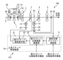
- FIG. 5 is a diagram for explaining a case where the mass flow on the delivery side of the first stand 1 is controlled by speed when the thickness of the delivery side of the first stand 1 is controlled by a roll gap.
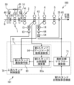
- FIG. 8 is a diagram for explaining a case where the mass flow on the delivery side of the third stand 3 is controlled by speed when the thickness of the delivery side of the third stand 3 is not controlled;
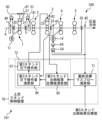
- FIG. 5 is a diagram for explaining a case where the mass flow on the delivery side of the first stand 1 is controlled by speed when the thickness of the delivery side of the first stand 1 is controlled by a roll gap.
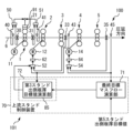
- FIG. 8 is a diagram for explaining a case where the mass flow on the delivery side of the third stand 3 is controlled by speed when the thickness of the delivery side of the third stand 3 is not controlled;
- FIG. 5 is a modified example of FIG. 4 and is a diagram for explaining a case in which a gauge meter plate thickness is substituted for the plate thickness measured by a plate thickness meter 33;
- FIG. 10 is a diagram for explaining a case where the mass flow on the delivery side of the third stand is controlled by the roll gap when the thickness of the delivery side of the third stand is not controlled;
- FIG. 7 is a modification of FIG. 6 and is a diagram for explaining a case in which a gauge meter plate thickness is substituted for the plate thickness measured by a plate thickness meter 33.
- FIG. FIG. 10 is a diagram for explaining a case where the delivery-side mass flow of the third stand 3 is controlled by speed when the delivery-side plate thickness of the third stand 3 is controlled by speed;
- FIG. 10 is a diagram for explaining a case where the mass flow on the delivery side of the first stand is controlled by the roll gap when the thickness of the delivery side of the first stand is controlled by the roll gap;
- FIG. 12 is a diagram for explaining a case where the thickness of the delivery side of the third stand is controlled by the roll gap, and the mass flow on the delivery side of the third stand is controlled by the roll gap.
- a case will be described in which when the thickness of the delivery side of the third stand 3 is controlled by speed, the mass flow on the delivery side of the third stand 3 is controlled by speed (without changing the target value for thickness control).
- FIG. 1 It is a diagram for A case will be described in which when the thickness of the delivery side of the third stand 3 is controlled by speed, the mass flow on the delivery side of the third stand 3 is controlled by speed (without changing the target value for thickness control).
- FIG. 2 It is a diagram for 2 is a block diagram showing a hardware configuration example of the control device 101; FIG.
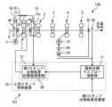
- the tandem cold rolling system shown in FIG. 1 includes a tandem cold rolling mill 100 .
- the tandem cold rolling mill 100 has N (N ⁇ 3) rolling stands that continuously roll the material 6 to be rolled.
- a “rolling stand” is simply referred to herein as a "stand”.
- FIG. 1 illustrates five stands (first stand 1 to fifth stand 5) arranged in tandem. Each stand has a work roll and a backup roll.
- Each stand is equipped with a roll speed actuator that controls work roll speed.
- Roll speed actuators include, for example, electric motors.
- FIG. 1 illustrates the roll speed actuator 11 of the first stand 1 and the roll speed actuator 14 of the fourth stand 4 .
- Each stand is equipped with a roll gap actuator that controls the roll gap (rolling amount) of the work rolls.
- Roll gap actuators include, for example, screw down devices.
- FIG. 1 illustrates the roll gap actuator 21 of the first stand 1 .
- the plate thickness gauge 30 is provided on the entry side of the first stand 1 and measures the plate thickness of the material 6 to be rolled that has passed directly below.
- a plate thickness meter 31 is provided on the delivery side of the first stand 1 and measures the plate thickness of the material 6 to be rolled that has passed directly below.
- a plate thickness meter 35 is provided on the delivery side of the fifth stand, which is the final stand, and measures the plate thickness of the material 6 to be rolled that has passed directly below.
- the speedometer 40 is provided on the entry side of the first stand 1 and measures the conveying speed of the material 6 to be rolled that has passed directly under it.
- a speedometer 41 is provided on the delivery side of the first stand 1 and measures the conveying speed of the material 6 to be rolled that has passed directly under it.
- a speedometer 45 is provided on the exit side of the fifth stand, which is the final stand, and measures the conveying speed of the material to be rolled 6 that has passed directly under it.
- tandem rolling mill for cold rolling is exemplified, but a tandem rolling mill for hot rolling may be used.
- the control device 101 of the tandem cold rolling mill 100 includes a speed control device, a reduction control device, an FF control device, an FB control device, an upstream stand control device 70, and the like, which are shown in the respective drawings described later. It has a function as a mass flow controller.
- the material 6 to be rolled is conveyed from the left side to the right side in FIG. 1 and rolled to a desired thickness by thickness control. For example, the following plate thickness control is performed.
- the FF control device 50 inputs the first stand entry-side plate thickness actual value measured by the plate thickness gauge 30 and the first stand entry-side speed actual value measured by the speedometer 40 .
- the FF control device 50 outputs an operation amount corresponding to the first stand entry side thickness actual value at the timing when the position of the material to be rolled 6 whose thickness is measured reaches directly below the work roll of the first stand 1 .
- the FB control device 51 inputs the first stand delivery side plate thickness actual value measured by the plate thickness gauge 31 and the first stand delivery side speed actual value measured by the speedometer 41 .
- the FB control device 51 correlates the value obtained by multiplying the difference between the first stand delivery side thickness actual value and the first stand delivery side thickness target value predetermined according to the product specifications of the material to be rolled 6 by a gain (coefficient). output the FB correction manipulated variable.
- the gain is set larger as the first stand delivery side speed actual value measured by the speedometer 41 or the rolling speed of the first stand 1 by the roll speed actuator 11 increases.
- the manipulated variable output from each of the FF control device 50 and the FB control device 51 is added and then input to the first roll-down control device 91 .
- the first rolling control device 91 controls the thickness of the delivery side of the first stand 1 by driving the roll gap actuator 21 and adjusting the roll gap between the upper and lower work rolls.
- the plate thickness control unit adjusts the delivery side plate thickness of the first stand 1 with the roll gap actuator 21 so that the first stand delivery side plate thickness actual value coincides with the first stand delivery side plate thickness target value determined in advance. Control.
- the thickness of the material to be rolled 6 immediately below the first stand 1 is estimated and calculated from the measured values of thickness gauges and speedometers on the entry and exit sides (referred to as mass flow thickness). ), and mass flow plate thickness control (not shown) for controlling the plate thickness based on this.
- mass flow thickness the measured values of thickness gauges and speedometers on the entry and exit sides
- mass flow plate thickness control (not shown) for controlling the plate thickness based on this.
- the FB control device 54 inputs the fifth stand delivery side plate thickness actual value measured by the plate thickness gauge 35 and the fifth stand delivery side speed actual value measured by the speedometer 45 .
- the FB control device 54 correlates a value obtained by multiplying a gain (coefficient) by the difference between the fifth stand delivery side thickness actual value and the fifth stand delivery side thickness target value predetermined according to the product specifications of the material 6 to be rolled. output the FB correction manipulated variable.
- the gain is set larger as the actual speed value of the delivery side of the fifth stand measured by the speedometer 45 is larger.
- the fourth speed control device 64 drives the roll speed actuator 14 based on the FB correction operation amount input from the FB control device 54 to adjust the work roll speed of the fourth stand 4, so that the fifth stand 5 Controls the thickness of the exit side of the
- the plate thickness control section causes the roll speed actuator 14 of the fourth stand to adjust the thickness of the fifth stand 5 so that the actual value of the plate thickness on the delivery side of the fifth stand matches the predetermined target value of the plate thickness on the delivery side of the fifth stand. Control the strip thickness on the delivery side.
- Embodiment 1 will be described with reference to FIGS. 1 and 2.
- FIG. 1 a case will be described in which the mass flow on the delivery side of the i-th stand is controlled by the speed when the thickness of the delivery side of the i-th stand is not controlled by the speed.
- the actuator used for plate thickness control on the delivery side of the i-th stand is separate from the actuator used for upstream mass flow control on the delivery side of the i-th stand (FIG. 1).
- FIG. 1 is a diagram for explaining a case in which the mass flow on the delivery side of the first stand 1 is controlled by speed when the thickness of the delivery side of the first stand 1 is controlled by a roll gap.
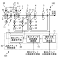
- FIG. 2 is a diagram for explaining a case where the mass flow on the delivery side of the third stand 3 is controlled by speed when the thickness of the delivery side of the third stand 3 is not controlled.
- the upstream mass flow control which is a feature of the control device 101, will be described.
- the controller 101 includes an upstream stand controller 70 .
- the upstream stand control device 70 includes a final target mass flow calculator 71 and an upstream mass flow controller 72 .
- the final target mass flow calculator 71 is determined in advance according to the actual speed value of the material to be rolled 6 measured at the delivery side of the fifth stand 5 (Nth stand), which is the final stand, and the product specifications of the material to be rolled 6.
- the final stand delivery side strip thickness target value is multiplied to calculate the final target mass flow, which is the delivery side mass flow of the final stand.
- the actual speed value may be a measured value measured by the speedometer 45, or the rotation speed of the tension meter roll or shape meter roll installed on the delivery side of the final stand and the roll of the corresponding roll It may be a calculated value calculated from the product of diameters.
- the upstream mass flow control unit 72 controls the actuator provided at the i-th stand so that the exit-side mass flow of the i-th stand (1 ⁇ i ⁇ N-2) coincides with the final target mass flow.
- the upstream mass flow control section 72 in FIG. 1 controls the roll speed actuator 11 provided in the first stand 1 so that the delivery side mass flow of the first stand 1 coincides with the final target mass flow.
- the processing of the upstream mass flow control unit 72 will be specifically described.
- the upstream mass flow control section 72 includes a first stand delivery side speed calculation section 80 and a first stand speed operation section 81 .
- the upstream mass flow control section 72 may include a first speed control device 61 .
- the first stand delivery side speed calculator 80 inputs the final target mass flow from the final target mass flow calculator 71 .
- the first stand delivery side speed calculator 80 divides the final target mass flow by the first stand delivery side plate thickness target value predetermined according to the product specifications of the material to be rolled 6 to obtain the first stand delivery side speed target value. calculate.
- the first stand speed operation section 81 obtains the actual speed value of the rolled material 6 on the delivery side of the first stand 1 from the speedometer 41, and the first stand delivery side speed target value from the first stand delivery side speed calculation section 80. ,input.
- the first stand speed operation unit 81 adjusts the actual speed value and the first stand delivery side speed value so that the actual speed value of the material to be rolled 6 on the delivery side of the first stand 1 matches the target speed value on the delivery side of the first stand.
- a correction manipulated variable corresponding to the difference from the speed target value is output to the first speed control device 61 .
- the first speed control device 61 controls the work roll speed of the first stand 1 with the roll speed actuator 11 according to the correction operation amount.
- the mass flow on the delivery side of the first stand 1 can be matched with the final target mass flow on the delivery side of the fifth stand 5.
- the mass flow on the delivery side of the most upstream stand at an early stage it is possible to reduce strip thickness fluctuations at the final stand, and to quickly and satisfactorily control the strip thickness on the delivery side of the final stand.
- FIG. 2 is a diagram for explaining a case where the mass flow on the delivery side of the third stand is controlled by speed when the thickness of the delivery side of the third stand is not controlled.
- the basic configurations of the tandem cold rolling mill 100 and the control device 101 shown in FIG. 2 are the same as those in FIG. 1, and thus description thereof is omitted.
- a speedometer 43 is provided on the delivery side of the third stand 3 and measures the conveying speed of the material 6 to be rolled that has passed directly under it.
- the upstream mass flow control which is a feature of the control device 101, will be described.
- the controller 101 includes an upstream stand controller 70 .
- the upstream stand control device 70 includes a final target mass flow calculator 71 and an upstream mass flow controller 72 .
- the processing contents of the final target mass flow calculator 71 are the same as those in FIG. 1 described above.
- the upstream mass flow controller 72 in FIG. 2 controls the roll speed actuator 13 provided on the third stand 3 so that the delivery side mass flow of the third stand 3 matches the final target mass flow.
- the processing of the upstream mass flow control unit 72 will be specifically described.
- the upstream mass flow control section 72 includes a third stand delivery side speed calculation section 82 and a third stand speed operation section 83 .
- the upstream mass flow controller 72 may include a third speed controller 63 .
- the third stand delivery side speed calculator 82 inputs the final target mass flow from the final target mass flow calculator 71 .
- a third stand delivery side speed calculator 82 divides the final target mass flow by a third stand delivery side plate thickness target value determined in advance according to the product specifications of the material to be rolled 6 to obtain a third stand delivery side speed target value. calculate.
- the third stand speed operation section 83 obtains the actual speed value of the rolled material 6 on the delivery side of the third stand 3 from the speedometer 43, and the third stand delivery side speed target value from the third stand delivery side speed calculation section 82. ,input.
- the third stand speed operation unit 83 adjusts the actual speed value and the third stand delivery side speed value so that the actual speed value of the material to be rolled 6 on the delivery side of the third stand 3 matches the third stand delivery side speed target value.
- a correction manipulated variable corresponding to the difference from the speed target value is output to the third speed control device 63 .
- the third speed control device 63 controls the work roll speed of the third stand 3 with the roll speed actuator 13 according to the correction operation amount.
- the mass flow on the delivery side of the third stand 3 can be matched with the final target mass flow on the delivery side of the fifth stand 5.
- the mass flow on the delivery side of the upstream stand at an early stage it is possible to reduce strip thickness fluctuations at the final stand, and to quickly and satisfactorily control the strip thickness on the delivery side of the final stand.
- Embodiment 2 will be described with reference to FIGS. 3 to 5.
- the first stand delivery side speed calculation unit 80 uses the first stand delivery side plate thickness target value (third stand delivery side plate thickness target value).
- the first stand delivery side speed calculator 80a uses the plate thickness actual value.
- the actuator used for plate thickness control on the delivery side of the i-th stand and the actuator used for upstream mass flow control on the delivery side of the i-th stand are separate (Fig. 3).
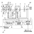
- FIG. 3 is a diagram for explaining a case in which the mass flow on the delivery side of the first stand 1 is controlled by speed when the thickness of the delivery side of the first stand 1 is controlled by the roll gap.
- FIG. 4 is a diagram for explaining a case in which the mass flow on the delivery side of the third stand 3 is controlled by speed when the thickness of the delivery side of the third stand 3 is not controlled.
- FIG. 5 is a modification of FIG. 4, and is a diagram for explaining a case in which the plate thickness measured by the plate thickness meter 33 is replaced by the gauge meter plate thickness.
- FIG. 3 Platinum thickness control: roll gap / upstream mass flow control: speed
- the upstream mass flow control which is a feature of the control device 101, will be described.
- the controller 101 includes an upstream stand controller 70 .
- the upstream stand control device 70 includes a final target mass flow calculator 71 and an upstream mass flow controller 72 .
- the processing contents of the final target mass flow calculator 71 are the same as those in FIG. 1 described above.
- the upstream mass flow control unit 72 in FIG. 3 controls the roll speed actuator 11 provided on the first stand 1 so that the delivery-side mass flow of the first stand 1 matches the final target mass flow.
- the upstream mass flow control section 72 includes a first stand delivery side speed calculation section 80 a and a first stand speed operation section 81 .
- the upstream mass flow control section 72 may include a first speed control device 61 .
- the first stand delivery side speed calculation unit 80 a inputs the final target mass flow from the final target mass flow calculation unit 71 and the first stand delivery side plate thickness actual value from the plate thickness gauge 31 .
- the first stand delivery side speed calculator 80a divides the final target mass flow by the first stand delivery side board thickness actual value measured on the delivery side of the first stand 1 to calculate the first stand delivery side speed target value. .
- the first stand speed operation unit 81 obtains the actual speed value of the rolled material 6 on the delivery side of the first stand 1 from the speedometer 41, from the first stand delivery side speed calculation unit 80a to the first Enter the 1-stand delivery side speed target value.
- the first stand speed operation unit 81 adjusts the actual speed value and the first stand delivery side speed value so that the actual speed value of the material to be rolled 6 on the delivery side of the first stand 1 matches the target speed value on the delivery side of the first stand.
- a correction manipulated variable corresponding to the difference from the speed target value is output to the first speed control device 61 .
- the first speed control device 61 controls the work roll speed of the first stand 1 with the roll speed actuator 11 according to the correction operation amount.
- the mass flow on the delivery side of the first stand 1 matches the final target mass flow on the delivery side of the fifth stand 5, as in FIG. can be made Therefore, similar effects can be exhibited.
- FIG. 4 is a diagram for explaining a case in which the mass flow on the delivery side of the third stand 3 is controlled by speed when the thickness of the delivery side of the third stand 3 is not controlled.
- the basic configurations of the tandem cold rolling mill 100 and the control device 101 shown in FIG. 4 are the same as those in FIG. 1, and thus description thereof is omitted.
- the tandem cold rolling mill 100 shown in FIG. 4 includes a plate thickness gauge 33 and a speedometer 43.
- the plate thickness meter 33 is provided on the delivery side of the third stand 3 and measures the plate thickness of the material 6 to be rolled that has passed directly below.
- a speedometer 43 is provided on the delivery side of the third stand 3 and measures the conveying speed of the material 6 to be rolled that has passed directly under it.
- the upstream mass flow control which is a feature of the control device 101, will be described.
- the controller 101 includes an upstream stand controller 70 .
- the upstream stand control device 70 includes a final target mass flow calculator 71 and an upstream mass flow controller 72 .
- the processing contents of the final target mass flow calculator 71 are the same as those in FIG. 1 described above.
- the upstream mass flow controller 72 in FIG. 4 controls the roll speed actuator 13 provided on the third stand 3 so that the delivery side mass flow of the third stand 3 matches the final target mass flow.
- the processing of the upstream mass flow control unit 72 will be specifically described.
- the upstream mass flow control section 72 includes a third stand delivery side speed calculation section 82 a and a third stand speed operation section 83 .
- the upstream mass flow controller 72 may include a third speed controller 63 .
- the third stand delivery side speed calculation unit 82 a receives the final target mass flow from the final target mass flow calculation unit 71 and the third stand delivery side plate thickness actual value from the plate thickness gauge 33 .
- the third stand delivery side speed calculator 82a divides the final target mass flow by the third stand delivery side plate thickness actual value measured on the delivery side of the third stand 3 to calculate the third stand delivery side speed target value. .
- the third stand speed operation section 83 obtains the actual speed value of the rolled material 6 on the delivery side of the third stand 3 from the speedometer 43, from the third stand delivery side speed calculation section 82a to the Enter the 3-stand delivery side speed target value.
- the third stand speed operation unit 83 adjusts the actual speed value and the third stand delivery side speed value so that the actual speed value of the material to be rolled 6 on the delivery side of the third stand 3 matches the third stand delivery side speed target value.
- a correction manipulated variable corresponding to the difference from the speed target value is output to the third speed control device 63 .
- the third speed control device 63 controls the work roll speed of the third stand 3 with the roll speed actuator 13 according to the correction operation amount.
- the mass flow on the delivery side of the third stand 3 matches the final target mass flow on the delivery side of the fifth stand 5, as in FIG. can be made Therefore, similar effects can be exhibited.
- FIG. 5 is a modification of FIG. 4, and is a diagram for explaining a case in which the plate thickness measured by the plate thickness meter 33 is replaced by the gauge meter plate thickness.
- the basic configuration of the tandem cold rolling mill 100 and the control device 101 shown in FIG. 5 is the same as in FIG.
- a speedometer 43 is provided on the delivery side of the third stand 3 and measures the conveying speed of the material 6 to be rolled that has passed directly under it.
- the upstream mass flow control which is a feature of the control device 101, will be described.
- the controller 101 includes an upstream stand controller 70 .
- the upstream stand control device 70 includes a final target mass flow calculator 71 and an upstream mass flow controller 72 .
- the processing contents of the final target mass flow calculator 71 are the same as those in FIG. 1 described above.
- the upstream mass flow controller 72 in FIG. 5 controls the roll speed actuator 13 provided in the third stand 3 so that the delivery side mass flow of the third stand 3 matches the final target mass flow.
- the upstream mass flow control section 72 includes a third stand delivery side speed calculation section 82 a , a third stand speed operation section 83 , and a third stand gauge meter plate thickness calculation section 84 .
- the upstream mass flow controller 72 may include a third speed controller 63 .
- the third stand gauge meter plate thickness calculator 84 inputs the actual roll gap value and the actual rolling load value of the third stand 3 .
- the third stand gauge meter plate thickness calculator 84 calculates the gauge meter plate thickness using the following equation (1).
- h is the delivery side plate thickness (gauge meter plate thickness)
- S is the roll gap actual value
- P is the rolling load actual value
- M is the mill constant given in advance.
- the third stand delivery side speed calculator 82 a inputs the final target mass flow from the final target mass flow calculator 71 and the gauge meter plate thickness from the third stand gauge meter plate thickness calculator 84 .
- the thickness of the gauge meter corresponds to the actual value of thickness on the delivery side of the third stand.
- the processing contents of the third stand exit side speed calculation unit 82a and the third stand speed operation unit 83 are the same as those in FIG. 4 described above.
- the mass flow on the delivery side of the third stand 3 matches the final target mass flow on the delivery side of the fifth stand 5, as in FIG. can be made Therefore, similar effects can be exhibited.
- Embodiment 3 will be described with reference to FIGS. 6 and 7.
- the mass flow on the delivery side of the i-th stand is controlled by the velocity
- the mass flow on the delivery side of the i-th stand is controlled by the roll gap It is different in that it is controlled by the mass flow on the delivery side of the i-th stand is controlled by the roll gap It is different in that it is controlled by
- FIG. 6 is a diagram for explaining a case in which the mass flow on the delivery side of the third stand is controlled by the roll gap when the thickness of the delivery side of the third stand is not controlled.
- FIG. 7 is a modification of FIG. 6, and is a diagram for explaining a case in which the plate thickness measured by the plate thickness meter 33 is replaced by the gauge meter plate thickness.
- FIG. 6 plate thickness control: none / upstream mass flow control: roll gap
- the plate thickness meter 33 is provided on the delivery side of the third stand 3 and measures the plate thickness of the material 6 to be rolled that has passed directly below.
- a speedometer 43 is provided on the delivery side of the third stand 3 and measures the conveying speed of the material 6 to be rolled that has passed directly under it.
- the upstream mass flow control which is a feature of the control device 101, will be described.
- the controller 101 includes an upstream stand controller 70 .
- the upstream stand control device 70 includes a final target mass flow calculator 71 and an upstream mass flow controller 72 .
- the processing contents of the final target mass flow calculator 71 are the same as those in FIG. 1 described above.
- the upstream mass flow control unit 72 in FIG. 6 controls the roll gap actuator 23 provided on the third stand 3 so that the delivery side mass flow of the third stand 3 matches the final target mass flow.
- the upstream mass flow control section 72 includes a third stand delivery side plate thickness target value calculation section 85 , a third stand reduction operation amount calculation section 86 , and a third stand reduction operation section 87 .
- the upstream mass flow control section 72 may include a third draft control device 93 .
- the third stand delivery side plate thickness target value calculation unit 85 inputs the final target mass flow from the final target mass flow calculation unit 71 and the actual speed value of the rolled material 6 on the delivery side of the third stand 3 from the speedometer 43 .
- the third stand delivery side plate thickness target value calculation unit 85 divides the final target mass flow by the third stand delivery side speed actual value of the material to be rolled 6 measured on the delivery side of the third stand to obtain a new third stand. Calculate the delivery side plate thickness target value.
- the third stand reduction operation amount calculation unit 86 inputs the third stand delivery side plate thickness actual value from the plate thickness gauge 33 and the new third stand delivery side plate thickness target value from the third stand delivery side plate thickness target value calculation unit 85 . do.
- the third stand roll-down operation amount calculation unit 86 adjusts the third stand delivery side strip thickness actual value measured on the delivery side of the third stand so as to match the new third stand delivery side strip thickness target value.
- a correction operation amount corresponding to the difference between the side plate thickness actual value and the new third stand delivery side plate thickness target value is calculated.
- the third stand reduction operation section 87 outputs the corrected operation amount to the third reduction control device 93 .
- the third roll-down control device 93 controls the roll gap of the third stand 3 with the roll gap actuator 23 according to the correction operation amount.
- tandem cold rolling system shown in FIG. It can be matched to the final target mass flow.
- mass flow on the delivery side of the upstream stand at an early stage it is possible to reduce strip thickness fluctuations at the final stand, and to quickly and satisfactorily control the strip thickness on the delivery side of the final stand.
- FIG. 7 is a modification of FIG. 6, and is a diagram for explaining a case in which the plate thickness measured by the plate thickness meter 33 is replaced by the gauge meter plate thickness.
- the basic configurations of the tandem cold rolling mill 100 and the control device 101 shown in FIG. 7 are the same as those in FIG. 1, and thus description thereof is omitted.
- a speedometer 43 is provided on the delivery side of the third stand 3 and measures the conveying speed of the material 6 to be rolled that has passed directly under it.
- the upstream mass flow control which is a feature of the control device 101, will be described.
- the controller 101 includes an upstream stand controller 70 .
- the upstream stand control device 70 includes a final target mass flow calculator 71 and an upstream mass flow controller 72 .
- the processing contents of the final target mass flow calculator 71 are the same as those in FIG. 1 described above.
- the upstream mass flow control unit 72 in FIG. 7 controls the roll gap actuator 23 provided on the third stand 3 so that the delivery-side mass flow of the third stand 3 matches the final target mass flow.
- the upstream mass flow control unit 72 includes a third stand gauge meter plate thickness calculation unit 84 , a third stand delivery side plate thickness target value calculation unit 85 , a third stand reduction operation amount calculation unit 86 a , and a third stand reduction operation unit 87 .
- the upstream mass flow control section 72 may include a third draft control device 93 .
- the processing contents of the third stand gauge meter plate thickness calculation unit 84 are the same as those in FIG. 5 described above. That is, the third stand gauge meter plate thickness calculator 84 inputs the actual roll gap value and the actual rolling load value of the third stand 3 . The third stand gauge meter plate thickness calculator 84 calculates the gauge meter plate thickness using the above-described formula (1).
- the processing contents of the 3rd stand delivery side plate thickness target value calculation unit 85 are the same as those in FIG. 6 described above.
- the third stand reduction operation amount calculation unit 86a calculates the gauge meter plate thickness from the third stand gauge meter plate thickness calculation unit 84, and calculates the new third stand delivery side plate thickness target value from the third stand delivery side plate thickness target value calculation unit 85. , enter The thickness of the gauge meter corresponds to the actual value of thickness on the delivery side of the third stand.
- the third stand roll-down operation amount calculation unit 86a adjusts the third stand delivery side strip thickness actual value measured on the delivery side of the third stand so as to match the new third stand delivery side strip thickness target value.
- a correction operation amount corresponding to the difference between the side plate thickness actual value and the new third stand delivery side plate thickness target value is calculated.
- the third stand reduction operation section 87 outputs the corrected operation amount to the third reduction control device 93 .
- the third roll-down control device 93 controls the roll gap of the third stand 3 with the roll gap actuator 23 according to the correction operation amount.
- Embodiment 4 will be described with reference to FIG. In the fourth embodiment, a case will be described in which the mass flow on the delivery side of the i-th stand is controlled by the velocity when the thickness of the delivery side of the i-th stand is controlled by the velocity.
- Embodiment 4 unlike Embodiments 1 to 3, the same actuator is used for plate thickness control on the delivery side of the i-th stand and the actuator used for upstream mass flow control on the delivery side of the i-th stand.
- FIG. 8 is a diagram for explaining a case where the mass flow on the delivery side of the third stand 3 is controlled by speed when the thickness of the delivery side of the third stand 3 is controlled by speed.
- the basic configurations of the tandem cold rolling mill 100 and the control device 101 shown in FIG. 8 are the same as those in FIG. 1, and thus description thereof is omitted.
- the plate thickness meter 33 is provided on the delivery side of the third stand 3 and measures the plate thickness of the material 6 to be rolled that has passed directly below.
- a speedometer 43 is provided on the delivery side of the third stand 3 and measures the conveying speed of the material 6 to be rolled that has passed directly under it.
- the configuration of the plate thickness control unit for controlling the plate thickness of the delivery side plate of the third stand 3 by speed will be described with reference to FIG. 8 .
- the FB control device 52 of the control device 101 inputs the third stand delivery side plate thickness actual value measured by the plate thickness gauge 33 and the third stand delivery side speed actual value measured by the speedometer 43 .
- the FB control device 52 correlates the value obtained by multiplying the difference between the third stand delivery side thickness actual value and the third stand delivery side thickness target value determined in advance according to the product specifications of the material to be rolled 6 by a gain (coefficient). output the FB correction manipulated variable.
- the gain is set larger as the third stand delivery side speed actual value measured by the speedometer 43 is larger.
- the second speed control device 62 drives the roll speed actuator 12 of the second stand 2 based on the FB correction operation amount input from the FB control device 52 to adjust the work roll speed of the second stand 2. , to control the delivery side plate thickness of the third stand 3 .
- the plate thickness control unit controls the second stand 2 so that the actual plate thickness value on the delivery side of the third stand coincides with the target value of plate thickness on the delivery side of the third stand that is predetermined according to the product specifications of the material 6 to be rolled.
- the thickness of the delivery side plate of the third stand 3 is controlled by the roll speed actuator 12 of .
- the upstream mass flow control which is a feature of the control device 101, will be described.
- the controller 101 includes an upstream stand controller 70 .
- the upstream stand control device 70 includes a final target mass flow calculator 71 and an upstream mass flow controller 72 .
- the processing contents of the final target mass flow calculator 71 are the same as those in FIG. 1 described above.
- the upstream mass flow control unit 72 is an actuator provided upstream of the i-th stand so that the delivery-side mass flow of the i-th stand (1 ⁇ i ⁇ N-2) matches the final target mass flow. to control.
- the upstream mass flow control section 72 in FIG. 8 controls the roll speed actuator 12 provided in the second stand 2 so that the delivery side mass flow of the third stand 3 coincides with the final target mass flow.
- the processing of the upstream mass flow control unit 72 will be specifically described.
- the upstream mass flow control section 72 includes a third stand delivery side plate thickness target value calculation section 85 .
- the upstream mass flow controller 72 may include a second speed controller 62 .
- the processing contents of the 3rd stand delivery side plate thickness target value calculation unit 85 are the same as those in FIG. 6 described above. That is, the third stand delivery side strip thickness target value calculation unit 85 inputs the final target mass flow from the final target mass flow calculation unit 71 and the actual speed value of the rolled material 6 on the delivery side of the third stand 3 from the speedometer 43. do. The third stand delivery side plate thickness target value calculation unit 85 divides the final target mass flow by the third stand delivery side speed actual value of the material to be rolled 6 measured on the delivery side of the third stand 3 to obtain a new third Calculate the target thickness of the stand delivery side.
- the upstream mass flow control unit 72 updates the predetermined third stand delivery side plate thickness target value used by the FB control device 52 (plate thickness control unit) to a new third stand delivery side plate thickness target value.
- the FB control device 52 outputs an FB correction operation amount that matches the third stand delivery side thickness actual value with the new third stand delivery side thickness target value.
- the second speed control device 62 drives the roll speed actuator 12 of the second stand 2 based on the FB correction operation amount to control the delivery side plate thickness of the third stand 3 .
- the same actuator i-1-th stand roll If a velocity actuator is used, the mass flow at the i-th stand exit can be matched to the final target mass flow.
- the mass flow on the delivery side of the upstream stand at an early stage it is possible to reduce strip thickness fluctuations at the final stand, and to quickly and satisfactorily control the strip thickness on the delivery side of the final stand.
- Embodiment 5 will be described with reference to FIGS. 9 and 10.
- FIG. In the fifth embodiment a case will be described in which when the thickness of the delivery side of the i-th stand is controlled by the roll gap, the mass flow on the delivery side of the i-th stand is controlled by the roll gap.
- Embodiment 5 unlike Embodiments 1 to 3, the actuator used for plate thickness control on the i-th stand delivery side and the actuator used for upstream mass flow control on the i-th stand delivery side are the same.
- FIG. 9 is a diagram for explaining a case where the roll gap controls the mass flow on the delivery side of the first stand when the thickness of the delivery side of the first stand is controlled by the roll gap.
- FIG. 10 is a diagram for explaining a case where the roll gap controls the mass flow on the delivery side of the third stand when the thickness of the delivery side of the third stand is controlled by the roll gap.
- FIG. 9 Plate thickness control: roll gap / upstream mass flow control: roll gap
- FIG. 9 A tandem cold rolling system shown in FIG. 9 will be described. Regarding the basic configuration of the tandem cold rolling mill 100 and the control device 101 shown in FIG. Since it is the same as FIG. 1, the description is omitted.
- the upstream mass flow control which is a feature of the control device 101, will be described.
- the controller 101 includes an upstream stand controller 70 .
- the upstream stand control device 70 includes a final target mass flow calculator 71 and an upstream mass flow controller 72 .
- the processing contents of the final target mass flow calculator 71 are the same as those in FIG. 1 described above.
- the upstream mass flow control unit 72 in FIG. 9 controls the roll gap actuator 21 provided on the first stand 1 so that the delivery-side mass flow of the first stand 1 matches the final target mass flow.
- the processing of the upstream mass flow control unit 72 will be specifically described.
- the upstream mass flow control section 72 includes a first stand delivery side plate thickness target value calculation section 88 .
- the upstream mass flow control section 72 may include a first draft control device 91 .
- the first stand delivery side plate thickness target value calculation unit 88 inputs the final target mass flow from the final target mass flow calculation unit 71 and the actual speed value of the rolled material 6 on the delivery side of the first stand 1 from the speedometer 41 .
- the first stand delivery side plate thickness target value calculation unit 88 divides the final target mass flow by the first stand delivery side velocity actual value of the material to be rolled 6 measured on the delivery side of the first stand 1 to obtain a new first Calculate the target thickness of the stand delivery side.
- the upstream mass flow control unit 72 updates the predetermined first stand delivery side plate thickness target value used by the FB control device 51 (plate thickness control unit) to a new first stand delivery side plate thickness target value.
- the FB control device 51 outputs the FB correction operation amount that matches the first stand delivery side thickness actual value with the new first stand delivery side thickness target value.
- the first rolling control device 91 drives the roll gap actuator 21 of the first stand 1 based on the FB correction operation amount to control the delivery side plate thickness of the first stand 1 .
- the same actuator i-th stand roll gap actuator
- the mass flow at the i-th stand exit can be matched to the final target mass flow.
- FIG. 10 is a diagram for explaining a case where the roll gap controls the mass flow on the delivery side of the third stand when the thickness of the delivery side of the third stand is controlled by the roll gap.
- the basic configurations of the tandem cold rolling mill 100 and the control device 101 shown in FIG. 10 are the same as those in FIG. 1, and thus description thereof is omitted.
- a tandem cold rolling mill 100 shown in FIG. 10 includes a thickness gauge 33 and a speedometer 43.
- the plate thickness meter 33 is provided on the delivery side of the third stand 3 and measures the plate thickness of the material 6 to be rolled that has passed directly below.
- a speedometer 43 is provided on the delivery side of the third stand 3 and measures the conveying speed of the material 6 to be rolled that has passed directly under it.
- the FB control device 53 of the control device 101 inputs the third stand delivery side plate thickness actual value measured by the plate thickness gauge 33 and the third stand delivery side speed actual value measured by the speedometer 43 .
- the FB control device 53 correlates the value obtained by multiplying the difference between the third stand delivery side thickness actual value and the third stand delivery side thickness target value determined in advance according to the product specifications of the material to be rolled 6 by a gain (coefficient). output the FB correction manipulated variable.
- the gain is set larger as the third stand delivery side speed actual value measured by the speedometer 43 is larger.
- the third roll-down control device 93 drives the roll gap actuator 23 based on the FB correction operation amount input from the FB control device 53 to adjust the roll gap between the upper and lower work rolls of the third stand 3. Control the thickness of the delivery side plate of the third stand 3 .
- the upstream mass flow control which is a feature of the control device 101, will be described.
- the controller 101 includes an upstream stand controller 70 .
- the upstream stand control device 70 includes a final target mass flow calculator 71 and an upstream mass flow controller 72 .
- the processing contents of the final target mass flow calculator 71 are the same as those in FIG. 1 described above.
- the upstream mass flow control unit 72 in FIG. 10 controls the roll gap actuator 23 provided on the third stand 3 so that the exit-side mass flow of the third stand 3 matches the final target mass flow.
- the processing of the upstream mass flow control unit 72 will be specifically described.
- the upstream mass flow control section 72 includes a third stand delivery side plate thickness target value calculation section 85 .
- the upstream mass flow control section 72 may include a third draft control device 93 .
- the processing contents of the 3rd stand delivery side plate thickness target value calculation unit 85 are the same as those in FIG. 6 described above. That is, the third stand delivery side strip thickness target value calculation unit 85 inputs the final target mass flow from the final target mass flow calculation unit 71 and the actual speed value of the rolled material 6 on the delivery side of the third stand 3 from the speedometer 43. do. The third stand delivery side plate thickness target value calculation unit 85 divides the final target mass flow by the third stand delivery side speed actual value of the material to be rolled 6 measured on the delivery side of the third stand to obtain a new third stand. Calculate the delivery side plate thickness target value.
- the upstream mass flow control unit 72 updates the predetermined third stand delivery side plate thickness target value used by the FB control device 53 (plate thickness control unit) to a new third stand delivery side plate thickness target value.
- the FB control device 53 outputs an FB correction operation amount that matches the third stand delivery side thickness actual value with the new third stand delivery side thickness target value.
- the third roll-down control device 93 drives the roll gap actuator 23 of the third stand 3 based on the FB correction operation amount to control the delivery side plate thickness of the first stand 1 .
- the mass flow at the i-th stand exit side can be matched with the final target mass flow.
- Embodiment 6 will be described with reference to FIGS. 11 and 12.
- FIG. In the sixth embodiment a case will be described in which the mass flow on the delivery side of the i-th stand is controlled by the velocity when the thickness of the delivery side of the i-th stand is controlled by the velocity. This point is the same as the fourth embodiment. However, while the target value of thickness control is changed in the fourth embodiment, the target value of thickness control is not changed in the sixth embodiment.
- Embodiment 6 unlike Embodiments 1 to 3, the actuator used for plate thickness control on the delivery side of the i-th stand and the actuator used for plate thickness control on the delivery side of the i-th stand are the same. . Further, although the actuator (roll speed) used for plate thickness control and mass flow control is the same as that of the fourth embodiment, the stand of the actuator used for plate thickness control and mass flow control is different in the sixth embodiment.
- FIG. 11 shows that when the thickness of the delivery side of the third stand 3 is controlled by speed, the mass flow on the delivery side of the third stand 3 is controlled by speed (without changing the target value of thickness control). It is a figure for demonstrating a case.
- FIG. 12 is a modification of FIG. 11, and is for explaining a case in which the third stand delivery side thickness actual value measured by the thickness gauge 33 is substituted for the predetermined third stand delivery side thickness target value. is a diagram.
- FIG. 11 Platinum thickness control: speed / upstream mass flow control: speed
- a tandem cold rolling mill 100 shown in FIG. 11 includes a thickness gauge 33 and a speedometer 43.
- the plate thickness meter 33 is provided on the delivery side of the third stand 3 and measures the plate thickness of the material 6 to be rolled that has passed directly below.
- a speedometer 43 is provided on the delivery side of the third stand 3 and measures the conveying speed of the material 6 to be rolled that has passed directly under it.
- the FB control device 52 of the control device 101 inputs the third stand delivery side plate thickness actual value measured by the plate thickness gauge 33 and the third stand delivery side speed actual value measured by the speedometer 43 .
- the FB control device 52 correlates the value obtained by multiplying the difference between the third stand delivery side thickness actual value and the third stand delivery side thickness target value determined in advance according to the product specifications of the material to be rolled 6 by a gain (coefficient). output the FB correction manipulated variable.
- the gain is set larger as the third stand delivery side speed actual value measured by the speedometer 43 is larger.
- the second speed control device 62 drives the roll speed actuator 12 of the second stand 2 based on the FB correction operation amount input from the FB control device 52 to adjust the work roll speed of the second stand 2. , to control the delivery side plate thickness of the third stand 3 .
- the plate thickness control unit controls the second stand 2 so that the actual plate thickness value on the delivery side of the third stand coincides with the target value of plate thickness on the delivery side of the third stand that is predetermined according to the product specifications of the material 6 to be rolled.
- the thickness of the delivery side plate of the third stand 3 is controlled by the roll speed actuator 12 of .
- the upstream mass flow control which is a feature of the control device 101, will be described.
- the controller 101 includes an upstream stand controller 70 .
- the upstream stand control device 70 includes a final target mass flow calculator 71 and an upstream mass flow controller 72 .
- the processing contents of the final target mass flow calculator 71 are the same as those in FIG. 1 described above.
- the upstream mass flow controller 72 in FIG. 11 controls the roll speed actuator 13 provided on the third stand 3 so that the delivery side mass flow of the third stand 3 matches the final target mass flow.
- the processing of the upstream mass flow control unit 72 will be specifically described.
- the upstream mass flow control section 72 includes a third stand delivery side speed calculation section 82 and a third stand speed operation section 83 .
- the upstream mass flow control section 72 may include a third speed control device 63 .
- the processing contents of the third stand delivery side speed calculation unit 82 are the same as those in FIG. 2 described above. That is, the third stand delivery side speed calculator 82 receives the final target mass flow from the final target mass flow calculator 71 .
- a third stand delivery side speed calculator 82 divides the final target mass flow by a third stand delivery side plate thickness target value determined in advance according to the product specifications of the material to be rolled 6 to obtain a third stand delivery side speed target value. calculate.
- the processing contents of the third stand speed operation unit 83 are the same as those in FIG. 2 described above. That is, the third stand speed operation section 83 obtains the actual speed value of the rolled material 6 on the delivery side of the third stand 3 from the speedometer 43, and calculates the third stand delivery side speed target from the third stand delivery side speed calculation section 82. Enter a value. The third stand speed operation unit 83 adjusts the actual speed value and the third stand delivery side speed value so that the actual speed value of the material to be rolled 6 on the delivery side of the third stand 3 matches the third stand delivery side target speed value. A correction manipulated variable corresponding to the difference from the speed target value is output to the third speed control device 63 . The third speed control device 63 controls the work roll speed of the third stand 3 with the roll speed actuator 13 according to the correction operation amount.
- the mass flow on the delivery side of the third stand 3 is changed to the final target mass flow on the delivery side of the fifth stand 5 without changing the target value of strip thickness control. can be matched.
- By adjusting the mass flow on the delivery side of the upstream stand at an early stage it is possible to reduce strip thickness fluctuations at the final stand, and to quickly and satisfactorily control the strip thickness on the delivery side of the final stand.
- FIG. 12 is a modification of FIG. 11, and is for explaining a case in which the third stand delivery side thickness actual value measured by the thickness gauge 33 is substituted for the predetermined third stand delivery side thickness target value.
- FIG. 12 is a diagram.
- the basic configurations of the tandem cold rolling mill 100 and the control device 101 shown in FIG. 12 are the same as those in FIG. 1, and thus description thereof is omitted.
- a tandem cold rolling mill 100 shown in FIG. 12 includes a thickness gauge 33 and a speedometer 43.
- the plate thickness meter 33 is provided on the delivery side of the third stand 3 and measures the plate thickness of the material 6 to be rolled that has passed directly below.
- a speedometer 43 is provided on the delivery side of the third stand 3 and measures the conveying speed of the material 6 to be rolled that has passed directly under it.
- the configuration and processing contents of the plate thickness control unit that controls the plate thickness on the delivery side of the third stand 3 by speed are the same as those in FIG.
- the upstream mass flow control which is a feature of the control device 101, will be described.
- the controller 101 includes an upstream stand controller 70 .
- the upstream stand control device 70 includes a final target mass flow calculator 71 and an upstream mass flow controller 72 .
- the processing contents of the final target mass flow calculator 71 are the same as those in FIG. 1 described above.
- the upstream mass flow controller 72 in FIG. 12 controls the roll speed actuator 13 provided on the third stand 3 so that the delivery side mass flow of the third stand 3 matches the final target mass flow.
- the processing of the upstream mass flow control unit 72 will be specifically described.
- the upstream mass flow control section 72 includes a third stand delivery side speed calculation section 82 a and a third stand speed operation section 83 .
- the upstream mass flow controller 72 may include a third speed controller 63 .
- the processing contents of the third stand delivery side speed calculation unit 82a are the same as those in FIG. 4 described above. That is, the third stand delivery side speed calculator 82 a inputs the final target mass flow from the final target mass flow calculator 71 and the third stand delivery side plate thickness actual value from the plate thickness gauge 33 . The third stand delivery side speed calculator 82a divides the final target mass flow by the third stand delivery side plate thickness actual value measured on the delivery side of the third stand 3 to calculate the third stand delivery side speed target value. .
- the processing contents of the third stand speed operation unit 83 are the same as those in FIG. 2 (FIG. 11) described above. That is, the third stand speed operation section 83 calculates the actual speed value of the rolled material 6 on the delivery side of the third stand 3 from the speedometer 43, and calculates the third stand delivery side speed target from the third stand delivery side speed calculation section 82a. Enter a value. The third stand speed operation unit 83 adjusts the actual speed value and the third stand delivery side speed value so that the actual speed value of the material to be rolled 6 on the delivery side of the third stand 3 matches the third stand delivery side speed target value. A correction manipulated variable corresponding to the difference from the speed target value is output to the third speed control device 63 . The third speed control device 63 controls the work roll speed of the third stand 3 with the roll speed actuator 13 according to the correction operation amount.
- the mass flow on the delivery side of the third stand 3 matches the final target mass flow on the delivery side of the fifth stand 5, as in FIG. 11 described above. can be made Therefore, similar effects can be exhibited.
- FIG. 13 is a conceptual diagram showing a hardware configuration example of a processing circuit included in the control device 101 in each of the above-described embodiments.
- the functions of the controller are realized by processing circuitry.
- the processing circuitry comprises at least one processor 111 and at least one memory 112 .
- the processing circuitry comprises at least one piece of dedicated hardware 113 .
- each function is realized by software, firmware, or a combination of software and firmware. At least one of software and firmware is written as a program. Software and/or firmware are stored in memory 112 .
- the processor 111 implements each function by reading and executing a program stored in the memory 112 .
- the processing circuit comprises dedicated hardware 113
- the processing circuit is, for example, a single circuit, multiple circuits, a programmed processor, or a combination thereof. Each function is realized by a processing circuit.
Landscapes
- Engineering & Computer Science (AREA)
- Mechanical Engineering (AREA)
- Control Of Metal Rolling (AREA)
Priority Applications (3)
| Application Number | Priority Date | Filing Date | Title |
|---|---|---|---|
| JP2024500786A JP7559995B2 (ja) | 2022-02-16 | 2022-02-16 | タンデム圧延システム |
| CN202280021814.6A CN117098614B (zh) | 2022-02-16 | 2022-02-16 | 串列式轧制系统 |
| PCT/JP2022/006245 WO2023157144A1 (ja) | 2022-02-16 | 2022-02-16 | タンデム圧延システム |
Applications Claiming Priority (1)
| Application Number | Priority Date | Filing Date | Title |
|---|---|---|---|
| PCT/JP2022/006245 WO2023157144A1 (ja) | 2022-02-16 | 2022-02-16 | タンデム圧延システム |
Publications (1)
| Publication Number | Publication Date |
|---|---|
| WO2023157144A1 true WO2023157144A1 (ja) | 2023-08-24 |
Family
ID=87577800
Family Applications (1)
| Application Number | Title | Priority Date | Filing Date |
|---|---|---|---|
| PCT/JP2022/006245 Ceased WO2023157144A1 (ja) | 2022-02-16 | 2022-02-16 | タンデム圧延システム |
Country Status (3)
| Country | Link |
|---|---|
| JP (1) | JP7559995B2 (cg-RX-API-DMAC7.html) |
| CN (1) | CN117098614B (cg-RX-API-DMAC7.html) |
| WO (1) | WO2023157144A1 (cg-RX-API-DMAC7.html) |
Citations (5)
| Publication number | Priority date | Publication date | Assignee | Title |
|---|---|---|---|---|
| JPH0515918A (ja) * | 1991-07-10 | 1993-01-26 | Nippon Steel Corp | 熱間タンデム圧延機のスタンド間張力制御装置 |
| JPH06142739A (ja) * | 1992-10-30 | 1994-05-24 | Hitachi Ltd | タンデム圧延機の板厚制御装置 |
| JPH0957317A (ja) * | 1995-08-18 | 1997-03-04 | Hitachi Ltd | タンデム圧延機の板厚制御方法及び装置 |
| JPH11319924A (ja) * | 1998-05-21 | 1999-11-24 | Sumitomo Metal Ind Ltd | 被圧延材の厚さ制御方法及びその装置 |
| JP2016043360A (ja) * | 2014-08-19 | 2016-04-04 | 株式会社日立製作所 | 圧延制御装置、圧延制御方法および圧延制御プログラム |
Family Cites Families (6)
| Publication number | Priority date | Publication date | Assignee | Title |
|---|---|---|---|---|
| JP2811926B2 (ja) * | 1990-07-13 | 1998-10-15 | 石川島播磨重工業株式会社 | 圧延機の板厚制御装置 |
| JPH0531517A (ja) * | 1991-07-29 | 1993-02-09 | Kawasaki Steel Corp | タンデム圧延機の板厚制御方法 |
| JP3270723B2 (ja) * | 1996-12-02 | 2002-04-02 | 株式会社日立製作所 | タンデム圧延機の通板制御方法および圧延制御システム |
| JP2013022615A (ja) * | 2011-07-20 | 2013-02-04 | Kobe Steel Ltd | タンデム圧延機の板厚制御装置及び板厚制御方法 |
| KR101767810B1 (ko) * | 2013-08-28 | 2017-08-23 | 도시바 미쓰비시덴키 산교시스템 가부시키가이샤 | 압연기의 판 두께 제어 장치 |
| JP6627740B2 (ja) * | 2016-12-20 | 2020-01-08 | 東芝三菱電機産業システム株式会社 | タンデム冷間圧延機の板厚制御装置 |
-
2022
- 2022-02-16 CN CN202280021814.6A patent/CN117098614B/zh active Active
- 2022-02-16 JP JP2024500786A patent/JP7559995B2/ja active Active
- 2022-02-16 WO PCT/JP2022/006245 patent/WO2023157144A1/ja not_active Ceased
Patent Citations (5)
| Publication number | Priority date | Publication date | Assignee | Title |
|---|---|---|---|---|
| JPH0515918A (ja) * | 1991-07-10 | 1993-01-26 | Nippon Steel Corp | 熱間タンデム圧延機のスタンド間張力制御装置 |
| JPH06142739A (ja) * | 1992-10-30 | 1994-05-24 | Hitachi Ltd | タンデム圧延機の板厚制御装置 |
| JPH0957317A (ja) * | 1995-08-18 | 1997-03-04 | Hitachi Ltd | タンデム圧延機の板厚制御方法及び装置 |
| JPH11319924A (ja) * | 1998-05-21 | 1999-11-24 | Sumitomo Metal Ind Ltd | 被圧延材の厚さ制御方法及びその装置 |
| JP2016043360A (ja) * | 2014-08-19 | 2016-04-04 | 株式会社日立製作所 | 圧延制御装置、圧延制御方法および圧延制御プログラム |
Also Published As
| Publication number | Publication date |
|---|---|
| JPWO2023157144A1 (cg-RX-API-DMAC7.html) | 2023-08-24 |
| JP7559995B2 (ja) | 2024-10-02 |
| CN117098614B (zh) | 2026-01-20 |
| CN117098614A (zh) | 2023-11-21 |
Similar Documents
| Publication | Publication Date | Title |
|---|---|---|
| JP3947116B2 (ja) | 連続圧延機の走間板厚変更装置 | |
| JP6627740B2 (ja) | タンデム冷間圧延機の板厚制御装置 | |
| CN103402661B (zh) | 用于轧制金属带材的、具有多个轧机机座的轧钢机的控制量的测定方法 | |
| JP7151915B1 (ja) | 連続圧延システム | |
| US6185967B1 (en) | Strip threading speed controlling apparatus for tandem rolling mill | |
| US8347681B2 (en) | Method for rolling a sheet metal strip | |
| JP7559995B2 (ja) | タンデム圧延システム | |
| JP6801642B2 (ja) | 走間板厚変更方法および装置 | |
| CN114273440B (zh) | 在考虑频率行为下的轧制 | |
| US11806768B2 (en) | Edge drop control device | |
| JP5385643B2 (ja) | 多段圧延機における板厚制御方法及び板厚制御装置 | |
| JP2760292B2 (ja) | タンデム圧延機の制御方法 | |
| JP2022187303A (ja) | 蛇行制御装置 | |
| JP7375947B2 (ja) | タンデム冷間圧延機の制御システム | |
| JPH0347613A (ja) | 冷間タンデム圧延機の板厚制御装置 | |
| JP2004268084A (ja) | タンデム圧延機の板厚制御方法 | |
| JPH0581326B2 (cg-RX-API-DMAC7.html) | ||
| JP3125660B2 (ja) | 熱間連続圧延における板幅制御方法 | |
| JPH1015607A (ja) | 冷間圧延機の制御装置 | |
| JP2540249B2 (ja) | 圧延機の圧下スケジュ―ル決定方法 | |
| JP2001293510A (ja) | 熱間連続圧延機における走間板厚変更制御方法 | |
| JPS63123509A (ja) | 連続圧延機の板クラウン制御装置 | |
| JPH0531517A (ja) | タンデム圧延機の板厚制御方法 | |
| JPH0768305A (ja) | 金属帯板の冷間タンデム圧延制御方法及びその装置 | |
| JP3539311B2 (ja) | タンデム圧延機のスタンド間張力の制御方法及び装置 |
Legal Events
| Date | Code | Title | Description |
|---|---|---|---|
| WWE | Wipo information: entry into national phase |
Ref document number: 202317055294 Country of ref document: IN |
|
| WWE | Wipo information: entry into national phase |
Ref document number: 202280021814.6 Country of ref document: CN |
|
| 121 | Ep: the epo has been informed by wipo that ep was designated in this application |
Ref document number: 22926344 Country of ref document: EP Kind code of ref document: A1 |
|
| WWE | Wipo information: entry into national phase |
Ref document number: 2024500786 Country of ref document: JP |
|
| NENP | Non-entry into the national phase |
Ref country code: DE |
|
| 122 | Ep: pct application non-entry in european phase |
Ref document number: 22926344 Country of ref document: EP Kind code of ref document: A1 |