WO2023153412A1 - 玉軸受用樹脂製保持器及び玉軸受 - Google Patents
玉軸受用樹脂製保持器及び玉軸受 Download PDFInfo
- Publication number
- WO2023153412A1 WO2023153412A1 PCT/JP2023/004068 JP2023004068W WO2023153412A1 WO 2023153412 A1 WO2023153412 A1 WO 2023153412A1 JP 2023004068 W JP2023004068 W JP 2023004068W WO 2023153412 A1 WO2023153412 A1 WO 2023153412A1
- Authority
- WO
- WIPO (PCT)
- Prior art keywords
- pockets
- ball bearing
- retainer
- resin
- Prior art date
- Legal status (The legal status is an assumption and is not a legal conclusion. Google has not performed a legal analysis and makes no representation as to the accuracy of the status listed.)
- Ceased
Links
Images




Classifications
-
- F—MECHANICAL ENGINEERING; LIGHTING; HEATING; WEAPONS; BLASTING
- F16—ENGINEERING ELEMENTS AND UNITS; GENERAL MEASURES FOR PRODUCING AND MAINTAINING EFFECTIVE FUNCTIONING OF MACHINES OR INSTALLATIONS; THERMAL INSULATION IN GENERAL
- F16C—SHAFTS; FLEXIBLE SHAFTS; ELEMENTS OR CRANKSHAFT MECHANISMS; ROTARY BODIES OTHER THAN GEARING ELEMENTS; BEARINGS
- F16C33/00—Parts of bearings; Special methods for making bearings or parts thereof
- F16C33/30—Parts of ball or roller bearings
- F16C33/38—Ball cages
- F16C33/3887—Details of individual pockets, e.g. shape or ball retaining means
-
- F—MECHANICAL ENGINEERING; LIGHTING; HEATING; WEAPONS; BLASTING
- F16—ENGINEERING ELEMENTS AND UNITS; GENERAL MEASURES FOR PRODUCING AND MAINTAINING EFFECTIVE FUNCTIONING OF MACHINES OR INSTALLATIONS; THERMAL INSULATION IN GENERAL
- F16C—SHAFTS; FLEXIBLE SHAFTS; ELEMENTS OR CRANKSHAFT MECHANISMS; ROTARY BODIES OTHER THAN GEARING ELEMENTS; BEARINGS
- F16C33/00—Parts of bearings; Special methods for making bearings or parts thereof
- F16C33/30—Parts of ball or roller bearings
- F16C33/38—Ball cages
- F16C33/41—Ball cages comb-shaped
- F16C33/418—Details of individual pockets, e.g. shape or ball retaining means
-
- F—MECHANICAL ENGINEERING; LIGHTING; HEATING; WEAPONS; BLASTING
- F16—ENGINEERING ELEMENTS AND UNITS; GENERAL MEASURES FOR PRODUCING AND MAINTAINING EFFECTIVE FUNCTIONING OF MACHINES OR INSTALLATIONS; THERMAL INSULATION IN GENERAL
- F16C—SHAFTS; FLEXIBLE SHAFTS; ELEMENTS OR CRANKSHAFT MECHANISMS; ROTARY BODIES OTHER THAN GEARING ELEMENTS; BEARINGS
- F16C19/00—Bearings with rolling contact, for exclusively rotary movement
- F16C19/02—Bearings with rolling contact, for exclusively rotary movement with bearing balls essentially of the same size in one or more circular rows
- F16C19/04—Bearings with rolling contact, for exclusively rotary movement with bearing balls essentially of the same size in one or more circular rows for radial load mainly
- F16C19/06—Bearings with rolling contact, for exclusively rotary movement with bearing balls essentially of the same size in one or more circular rows for radial load mainly with a single row or balls
-
- F—MECHANICAL ENGINEERING; LIGHTING; HEATING; WEAPONS; BLASTING
- F16—ENGINEERING ELEMENTS AND UNITS; GENERAL MEASURES FOR PRODUCING AND MAINTAINING EFFECTIVE FUNCTIONING OF MACHINES OR INSTALLATIONS; THERMAL INSULATION IN GENERAL
- F16C—SHAFTS; FLEXIBLE SHAFTS; ELEMENTS OR CRANKSHAFT MECHANISMS; ROTARY BODIES OTHER THAN GEARING ELEMENTS; BEARINGS
- F16C33/00—Parts of bearings; Special methods for making bearings or parts thereof
- F16C33/30—Parts of ball or roller bearings
- F16C33/38—Ball cages
- F16C33/3837—Massive or moulded cages having cage pockets surrounding the balls, e.g. machined window cages
- F16C33/3843—Massive or moulded cages having cage pockets surrounding the balls, e.g. machined window cages formed as one-piece cages, i.e. monoblock cages
- F16C33/3856—Massive or moulded cages having cage pockets surrounding the balls, e.g. machined window cages formed as one-piece cages, i.e. monoblock cages made from plastic, e.g. injection moulded window cages
-
- F—MECHANICAL ENGINEERING; LIGHTING; HEATING; WEAPONS; BLASTING
- F16—ENGINEERING ELEMENTS AND UNITS; GENERAL MEASURES FOR PRODUCING AND MAINTAINING EFFECTIVE FUNCTIONING OF MACHINES OR INSTALLATIONS; THERMAL INSULATION IN GENERAL
- F16C—SHAFTS; FLEXIBLE SHAFTS; ELEMENTS OR CRANKSHAFT MECHANISMS; ROTARY BODIES OTHER THAN GEARING ELEMENTS; BEARINGS
- F16C33/00—Parts of bearings; Special methods for making bearings or parts thereof
- F16C33/30—Parts of ball or roller bearings
- F16C33/38—Ball cages
- F16C33/41—Ball cages comb-shaped
- F16C33/412—Massive or moulded comb cages, e.g. snap ball cages
- F16C33/414—Massive or moulded comb cages, e.g. snap ball cages formed as one-piece cages, i.e. monoblock comb cages
- F16C33/416—Massive or moulded comb cages, e.g. snap ball cages formed as one-piece cages, i.e. monoblock comb cages made from plastic, e.g. injection moulded comb cages
-
- F—MECHANICAL ENGINEERING; LIGHTING; HEATING; WEAPONS; BLASTING
- F16—ENGINEERING ELEMENTS AND UNITS; GENERAL MEASURES FOR PRODUCING AND MAINTAINING EFFECTIVE FUNCTIONING OF MACHINES OR INSTALLATIONS; THERMAL INSULATION IN GENERAL
- F16C—SHAFTS; FLEXIBLE SHAFTS; ELEMENTS OR CRANKSHAFT MECHANISMS; ROTARY BODIES OTHER THAN GEARING ELEMENTS; BEARINGS
- F16C2208/00—Plastics; Synthetic resins, e.g. rubbers
- F16C2208/02—Plastics; Synthetic resins, e.g. rubbers comprising fillers, fibres
-
- F—MECHANICAL ENGINEERING; LIGHTING; HEATING; WEAPONS; BLASTING
- F16—ENGINEERING ELEMENTS AND UNITS; GENERAL MEASURES FOR PRODUCING AND MAINTAINING EFFECTIVE FUNCTIONING OF MACHINES OR INSTALLATIONS; THERMAL INSULATION IN GENERAL
- F16C—SHAFTS; FLEXIBLE SHAFTS; ELEMENTS OR CRANKSHAFT MECHANISMS; ROTARY BODIES OTHER THAN GEARING ELEMENTS; BEARINGS
- F16C2208/00—Plastics; Synthetic resins, e.g. rubbers
- F16C2208/02—Plastics; Synthetic resins, e.g. rubbers comprising fillers, fibres
- F16C2208/04—Glass fibres
-
- F—MECHANICAL ENGINEERING; LIGHTING; HEATING; WEAPONS; BLASTING
- F16—ENGINEERING ELEMENTS AND UNITS; GENERAL MEASURES FOR PRODUCING AND MAINTAINING EFFECTIVE FUNCTIONING OF MACHINES OR INSTALLATIONS; THERMAL INSULATION IN GENERAL
- F16C—SHAFTS; FLEXIBLE SHAFTS; ELEMENTS OR CRANKSHAFT MECHANISMS; ROTARY BODIES OTHER THAN GEARING ELEMENTS; BEARINGS
- F16C2208/00—Plastics; Synthetic resins, e.g. rubbers
- F16C2208/20—Thermoplastic resins
-
- F—MECHANICAL ENGINEERING; LIGHTING; HEATING; WEAPONS; BLASTING
- F16—ENGINEERING ELEMENTS AND UNITS; GENERAL MEASURES FOR PRODUCING AND MAINTAINING EFFECTIVE FUNCTIONING OF MACHINES OR INSTALLATIONS; THERMAL INSULATION IN GENERAL
- F16C—SHAFTS; FLEXIBLE SHAFTS; ELEMENTS OR CRANKSHAFT MECHANISMS; ROTARY BODIES OTHER THAN GEARING ELEMENTS; BEARINGS
- F16C2208/00—Plastics; Synthetic resins, e.g. rubbers
- F16C2208/20—Thermoplastic resins
- F16C2208/36—Polyarylene ether ketones [PAEK], e.g. PEK, PEEK
-
- F—MECHANICAL ENGINEERING; LIGHTING; HEATING; WEAPONS; BLASTING
- F16—ENGINEERING ELEMENTS AND UNITS; GENERAL MEASURES FOR PRODUCING AND MAINTAINING EFFECTIVE FUNCTIONING OF MACHINES OR INSTALLATIONS; THERMAL INSULATION IN GENERAL
- F16C—SHAFTS; FLEXIBLE SHAFTS; ELEMENTS OR CRANKSHAFT MECHANISMS; ROTARY BODIES OTHER THAN GEARING ELEMENTS; BEARINGS
- F16C2208/00—Plastics; Synthetic resins, e.g. rubbers
- F16C2208/20—Thermoplastic resins
- F16C2208/52—Polyphenylene sulphide [PPS]
-
- F—MECHANICAL ENGINEERING; LIGHTING; HEATING; WEAPONS; BLASTING
- F16—ENGINEERING ELEMENTS AND UNITS; GENERAL MEASURES FOR PRODUCING AND MAINTAINING EFFECTIVE FUNCTIONING OF MACHINES OR INSTALLATIONS; THERMAL INSULATION IN GENERAL
- F16C—SHAFTS; FLEXIBLE SHAFTS; ELEMENTS OR CRANKSHAFT MECHANISMS; ROTARY BODIES OTHER THAN GEARING ELEMENTS; BEARINGS
- F16C2208/00—Plastics; Synthetic resins, e.g. rubbers
- F16C2208/20—Thermoplastic resins
- F16C2208/60—Polyamides [PA]
- F16C2208/62—Polyamides [PA] high performance polyamides, e.g. PA12, PA46
-
- F—MECHANICAL ENGINEERING; LIGHTING; HEATING; WEAPONS; BLASTING
- F16—ENGINEERING ELEMENTS AND UNITS; GENERAL MEASURES FOR PRODUCING AND MAINTAINING EFFECTIVE FUNCTIONING OF MACHINES OR INSTALLATIONS; THERMAL INSULATION IN GENERAL
- F16C—SHAFTS; FLEXIBLE SHAFTS; ELEMENTS OR CRANKSHAFT MECHANISMS; ROTARY BODIES OTHER THAN GEARING ELEMENTS; BEARINGS
- F16C2208/00—Plastics; Synthetic resins, e.g. rubbers
- F16C2208/20—Thermoplastic resins
- F16C2208/70—Polyesters, e.g. polyethylene-terephthlate [PET], polybutylene-terephthlate [PBT]
-
- F—MECHANICAL ENGINEERING; LIGHTING; HEATING; WEAPONS; BLASTING
- F16—ENGINEERING ELEMENTS AND UNITS; GENERAL MEASURES FOR PRODUCING AND MAINTAINING EFFECTIVE FUNCTIONING OF MACHINES OR INSTALLATIONS; THERMAL INSULATION IN GENERAL
- F16C—SHAFTS; FLEXIBLE SHAFTS; ELEMENTS OR CRANKSHAFT MECHANISMS; ROTARY BODIES OTHER THAN GEARING ELEMENTS; BEARINGS
- F16C2220/00—Shaping
- F16C2220/02—Shaping by casting
- F16C2220/04—Shaping by casting by injection-moulding
-
- F—MECHANICAL ENGINEERING; LIGHTING; HEATING; WEAPONS; BLASTING
- F16—ENGINEERING ELEMENTS AND UNITS; GENERAL MEASURES FOR PRODUCING AND MAINTAINING EFFECTIVE FUNCTIONING OF MACHINES OR INSTALLATIONS; THERMAL INSULATION IN GENERAL
- F16C—SHAFTS; FLEXIBLE SHAFTS; ELEMENTS OR CRANKSHAFT MECHANISMS; ROTARY BODIES OTHER THAN GEARING ELEMENTS; BEARINGS
- F16C2240/00—Specified values or numerical ranges of parameters; Relations between them
- F16C2240/08—Time
-
- F—MECHANICAL ENGINEERING; LIGHTING; HEATING; WEAPONS; BLASTING
- F16—ENGINEERING ELEMENTS AND UNITS; GENERAL MEASURES FOR PRODUCING AND MAINTAINING EFFECTIVE FUNCTIONING OF MACHINES OR INSTALLATIONS; THERMAL INSULATION IN GENERAL
- F16C—SHAFTS; FLEXIBLE SHAFTS; ELEMENTS OR CRANKSHAFT MECHANISMS; ROTARY BODIES OTHER THAN GEARING ELEMENTS; BEARINGS
- F16C2240/00—Specified values or numerical ranges of parameters; Relations between them
- F16C2240/26—Speed, e.g. rotational speed
-
- F—MECHANICAL ENGINEERING; LIGHTING; HEATING; WEAPONS; BLASTING
- F16—ENGINEERING ELEMENTS AND UNITS; GENERAL MEASURES FOR PRODUCING AND MAINTAINING EFFECTIVE FUNCTIONING OF MACHINES OR INSTALLATIONS; THERMAL INSULATION IN GENERAL
- F16C—SHAFTS; FLEXIBLE SHAFTS; ELEMENTS OR CRANKSHAFT MECHANISMS; ROTARY BODIES OTHER THAN GEARING ELEMENTS; BEARINGS
- F16C2240/00—Specified values or numerical ranges of parameters; Relations between them
- F16C2240/30—Angles, e.g. inclinations
-
- F—MECHANICAL ENGINEERING; LIGHTING; HEATING; WEAPONS; BLASTING
- F16—ENGINEERING ELEMENTS AND UNITS; GENERAL MEASURES FOR PRODUCING AND MAINTAINING EFFECTIVE FUNCTIONING OF MACHINES OR INSTALLATIONS; THERMAL INSULATION IN GENERAL
- F16C—SHAFTS; FLEXIBLE SHAFTS; ELEMENTS OR CRANKSHAFT MECHANISMS; ROTARY BODIES OTHER THAN GEARING ELEMENTS; BEARINGS
- F16C2240/00—Specified values or numerical ranges of parameters; Relations between them
- F16C2240/40—Linear dimensions, e.g. length, radius, thickness, gap
-
- F—MECHANICAL ENGINEERING; LIGHTING; HEATING; WEAPONS; BLASTING
- F16—ENGINEERING ELEMENTS AND UNITS; GENERAL MEASURES FOR PRODUCING AND MAINTAINING EFFECTIVE FUNCTIONING OF MACHINES OR INSTALLATIONS; THERMAL INSULATION IN GENERAL
- F16C—SHAFTS; FLEXIBLE SHAFTS; ELEMENTS OR CRANKSHAFT MECHANISMS; ROTARY BODIES OTHER THAN GEARING ELEMENTS; BEARINGS
- F16C2240/00—Specified values or numerical ranges of parameters; Relations between them
- F16C2240/40—Linear dimensions, e.g. length, radius, thickness, gap
- F16C2240/56—Tolerances; Accuracy of linear dimensions
-
- F—MECHANICAL ENGINEERING; LIGHTING; HEATING; WEAPONS; BLASTING
- F16—ENGINEERING ELEMENTS AND UNITS; GENERAL MEASURES FOR PRODUCING AND MAINTAINING EFFECTIVE FUNCTIONING OF MACHINES OR INSTALLATIONS; THERMAL INSULATION IN GENERAL
- F16C—SHAFTS; FLEXIBLE SHAFTS; ELEMENTS OR CRANKSHAFT MECHANISMS; ROTARY BODIES OTHER THAN GEARING ELEMENTS; BEARINGS
- F16C2300/00—Application independent of particular apparatuses
- F16C2300/20—Application independent of particular apparatuses related to type of movement
- F16C2300/22—High-speed rotation
-
- F—MECHANICAL ENGINEERING; LIGHTING; HEATING; WEAPONS; BLASTING
- F16—ENGINEERING ELEMENTS AND UNITS; GENERAL MEASURES FOR PRODUCING AND MAINTAINING EFFECTIVE FUNCTIONING OF MACHINES OR INSTALLATIONS; THERMAL INSULATION IN GENERAL
- F16C—SHAFTS; FLEXIBLE SHAFTS; ELEMENTS OR CRANKSHAFT MECHANISMS; ROTARY BODIES OTHER THAN GEARING ELEMENTS; BEARINGS
- F16C2316/00—Apparatus in health or amusement
- F16C2316/10—Apparatus in health or amusement in medical appliances, e.g. in diagnosis, dentistry, instruments, prostheses, medical imaging appliances
- F16C2316/13—Dental machines
-
- F—MECHANICAL ENGINEERING; LIGHTING; HEATING; WEAPONS; BLASTING
- F16—ENGINEERING ELEMENTS AND UNITS; GENERAL MEASURES FOR PRODUCING AND MAINTAINING EFFECTIVE FUNCTIONING OF MACHINES OR INSTALLATIONS; THERMAL INSULATION IN GENERAL
- F16C—SHAFTS; FLEXIBLE SHAFTS; ELEMENTS OR CRANKSHAFT MECHANISMS; ROTARY BODIES OTHER THAN GEARING ELEMENTS; BEARINGS
- F16C33/00—Parts of bearings; Special methods for making bearings or parts thereof
- F16C33/30—Parts of ball or roller bearings
- F16C33/38—Ball cages
- F16C33/3806—Details of interaction of cage and race, e.g. retention, centring
Definitions
- the present invention relates to a resin cage for ball bearings and ball bearings, and for example, to a resin cage for ball bearings and ball bearings used for high-speed rotation in dental air turbines, cleaners, electric tools, and the like.
- resin cages applied to ball bearings are manufactured by injection molding. Specifically, an annular cavity corresponding to the retainer is formed in the mold, and a molten resin material (thermoplastic resin) is injected from a resin injection gate provided on the periphery of this cavity, and then cooled and solidified. A retainer is thereby manufactured.
- a molten resin material thermoplastic resin
- Patent Document 1 discloses, as a resin cage, a crown type cage having spherical pockets and a double ring type cage having cylindrical pockets. Further, in the angular contact ball bearing described in Patent Literature 2, a resin retainer having a pocket formed by combining a cylindrical portion and a diameter-reduced portion is disclosed.
- the present invention has been made in view of the problems described above, and an object thereof is to provide a resin cage for a ball bearing and a ball bearing capable of reducing the vibration of the cage during rotation of the bearing and improving the life of the bearing. That's what it is.
- Cylindrical or partial cylindrical shape comprising at least one annular portion and a plurality of pillars each extending axially from the annular portion, and formed between the adjacent pillars
- a ball bearing resin retainer capable of rotatably holding balls of a ball bearing in a pocket, wherein the annular portion has a guide surface guided by the inner peripheral surface of the outer ring or the outer peripheral surface of the inner ring of the ball bearing.
- the roundness of the guide surface is 5 ⁇ m or less,
- the difference between the angle between the centers of the adjacent pockets and 360°/the number of pockets is within ⁇ 0.1°,
- the directions of the centers of all the pockets are directed to either one side in the circumferential direction and one side in the axial direction from the outer diameter side to the inner diameter side, Resin cage for ball bearings.
- the sum of the differences between the angle between the centers of the two adjacent pockets and 360°/the number of pockets is within ⁇ 0.1°.
- the resin retainer for ball bearings according to [1].
- [3] The ball bearing resin retainer according to [1] or [2], wherein all the pockets are oriented within 1°.
- the roundness of the guide surface is 5 ⁇ m or less, and the difference between the angle between the centers of adjacent pockets and 360°/the number of pockets is All of them are within ⁇ 0.1°, and the direction of the center of all the pockets is toward either side in the circumferential direction and toward either side in the axial direction from the outer diameter side to the inner diameter side. Vibration of the retainer during rotation of the bearing can be reduced, and the life of the bearing can be improved.
- FIG. 1 is a vertical cross-sectional view of a main part of a deep groove ball bearing incorporating both ring-shaped retainers according to a first embodiment of the present invention
- FIG. FIG. 2 is a perspective view of both ring-shaped cages shown in FIG. 1
- FIG. 4 is a schematic diagram for explaining the orientation of the pockets of both ring-shaped cages
- 4(a) to 4(d) are schematic diagrams for explaining four aspects of pocket orientations of both annular retainers.
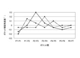
- FIG. FIG. 4 is a schematic diagram of both annular cages showing the difference in the equal pocket angle between pockets and the direction of the pockets. 4 is a graph showing equal pocket angular differences between pockets for three retainers of the present embodiment.
- FIG. 4 is a developed view of both ring-shaped cages for explaining variations in the bottom thickness of the pocket.
- FIG. 10 is a schematic diagram of both annular cages of a comparative example showing the equal pocket angle difference between pockets and the orientation of the pockets.
- 7 is a graph showing equal pocket angular differences between pockets for three cages as comparative examples. It is a graph which shows the relationship between roundness and rotation life time.
- 7 is a graph showing the relationship between the maximum value of the equal pocket angle difference between pockets, the number of deviations in pocket orientation, and the rotation life time.
- 7 is a graph showing the relationship between the maximum pocket orientation angle and the rotation life time.
- it is a perspective view of a crown-shaped retainer.
- the deep groove ball bearing 10 of this embodiment includes an outer ring 20 having an outer ring raceway groove 21 formed on its inner peripheral surface, an inner ring 30 having an inner ring raceway groove 31 formed on its outer peripheral surface, and an outer ring raceway.
- a resin retainer having a plurality of balls 11 rotatably disposed between the groove 21 and the inner ring raceway groove 31, and a plurality of cylindrical pockets P (see FIG. 2) for rotatably retaining the balls 11 respectively.
- a double ring-shaped retainer 40 that is a container.
- both ring-shaped retainers 40 are composed of a pair of ring portions 41 that are arranged to face each other in the axial direction, and a pair of ring portions 41 extending in the axial direction. 41, and a plurality of (seven in the embodiment shown in FIG. 10) pillars 42 arranged at equal intervals in the circumferential direction, and the pocket P includes the adjacent pillars 42 and a pair of annular rings. 41.
- Both annular retainers 40 are of an outer ring guide type, and the outer peripheral surfaces 46 of the pair of annular portions 41 are guided by the inner peripheral surface 22 of the shoulder portion of the outer ring 20 .
- Both annular retainers 40 may be manufactured by cutting or may be manufactured by injection molding.
- Examples of the resin material of the both ring-shaped retainers 40 include polyamide resins such as 46 nylon and 66 nylon, polybutylene terephthalate, polyphenylene sulfide (PPS), polyetheretherketone (PEEK), and polyethernitrile (PEN). , polyethylene terephthalate (PET), etc., to which 10 to 50 wt % of reinforcing fiber material (for example, glass fiber or carbon fiber) is added.
- polyamide resins such as 46 nylon and 66 nylon
- PPS polyphenylene sulfide
- PEEK polyetheretherketone
- PEN polyethernitrile
- PET polyethylene terephthalate
- reinforcing fiber material for example, glass fiber or carbon fiber
- the double ring-shaped retainer 40 of the present embodiment is designed to reduce vibration of the retainer 40 during rotation of the bearing even when used under high-speed rotation conditions of dmn 1,000,000 or more, thereby improving the life of the bearing.
- all of the following conditions (i) to (iii) are satisfied, and preferably at least one condition of (iv) to (vi) is further satisfied.
- the circularity of the outer peripheral surface 46 which is the guide surface, is 5 ⁇ m or less.
- the difference between the angle between the centers C of adjacent pockets P and 360°/the number of pockets (herein also referred to as the "equally arranged pocket angle difference between pockets P") is ⁇ within 0.1°.
- the direction of the center C of all the pockets P is toward one side in the circumferential direction and one side in the axial direction as it goes from the outer diameter side to the inner diameter side.
- the orientation of the centers C of all pockets P is within 1°.
- the total difference between the angle between the centers C of adjacent pockets P on both sides and 360°/the number of pockets is within ⁇ 0.1°.
- Variation in the bottom thickness T of each pocket P (that is, the minimum distance between the side surface on one axial side of the retainer 40 and each pocket P) is within 10 ⁇ m (see FIG. 7).
- the center C of the pocket P is, in terms of design, directed from the outer diameter side to the inner diameter side, as indicated by the two-dot chain line in FIG. It is designed so that it intersects and the axial position does not change over the radial direction. That is, on a plane that passes through the rotation axis center X and is perpendicular to the center C of the designed pocket P, the rotation axis center X is defined as the first axis L1, and the rotation axis passes through the center C in the axial direction.
- the center C of the pocket P passes through the intersection point XA between the first axis L1 and the second axis L2. is projected as a pocket P'.
- the pocket P is projected as a pocket P' indicated by a dotted line on a plane containing the first axis L1 and the second axis L2. That is, as shown in FIGS. 4(a) to 4(d), with the outer diameter side opening of the pocket P as a reference, the direction of the center C of the pocket P is 4 degrees with the first axis L1 and the second axis L2 as boundaries. It is formed staggered toward one of the three regions A1 to A4. On the other hand, in this embodiment, the pockets P are formed so that the centers C of all the pockets P face one of the four regions A1 to A4.
- the directions of the centers C of all the pockets P are the intersection point XA between the first axis L1 and the second axis L2 and the center position of the ball 11 (the center C of the pocket P and the center C of the ball 11
- the position where the pitch circle diameter intersects) C1 is intersected within 1°. That is, in FIG. 3, the orientation of the center C of the pocket P in design (the axis of the center C) indicated by the two-dot chain line and the orientation of the center C of the pocket P (the axis of the center C) indicated by the one-dot chain line.
- the angle formed by the axes of these two centers C on a plane containing the center C is within 1°.
- the direction of C is varied so as to face the region A2 in which the circumferential direction is positive and the axial direction is negative.
- the pockets P1 to P7 are arranged such that the direction of the center C of all the pockets P1 to P7 is the region A1 in which the circumferential direction is positive and the axial direction is positive. is formed.
- the condition (ii) in the case of the general cage which is a comparative example, as in the three examples shown in FIG. At some position, the range of ⁇ 0.1 is exceeded.
- the equal pocket angle difference between the pockets P7-P1 to P6-P7 is within the range of ⁇ 0.1 at any position. It is formed to be In the graphs of FIGS. 6 and 9, the dashed line corresponds to the equal pocket angular difference between the pockets P7-P1 to P6-7 in the retainer shown in FIGS.
- FIG. 10 shows the test results when the roundness of the guide surface was changed with respect to condition (i) in a retainer that satisfies conditions (ii) to (vi). As can be seen from this result, if the roundness of the guide surface is 5 ⁇ m or less, any cage can be used without breakage up to a predetermined rotation life time (400 hours).
- FIG. 11 shows a cage that satisfies the conditions (i), (iv), and (vi), with respect to the condition (ii), by changing the maximum value of the equal pocket angular difference between the pockets, and Regarding (iii), the test results are shown when the number of shifts in the pocket direction is changed.
- the circularity of the guide surface is 5 ⁇ m or less
- the maximum value of the equal pocket angle difference between the pockets is ⁇ 0.1° or less
- all the pockets are oriented in the circumferential direction. If it is directed to either side, or to either side in the axial direction, the cage can be used without breakage up to a predetermined rotation life time (1000 hours).
- FIG. 12 shows the case where the maximum value of the direction of the center C of all pockets P is changed with respect to condition (iv) while satisfying conditions (i) to (iii), (v), and (vi). shows the test results of As can be seen from this result, if the maximum value of the directions of the centers C of all the pockets P is within 1°, a rotational life of 1000 hours or longer can be obtained.
- condition (v) for any given pocket P, the sum of the differences between the angle between the centers of adjacent pockets P on both sides and 360°/the number of pockets must be within ⁇ 0.1°. By doing so, it is possible to further extend the rotational life of the retainer without breakage.
- the circularity of the guide surface is 5 ⁇ m or less, and the difference between the angle between the centers of adjacent pockets and the number of pockets is 360°/the number of pockets. , Both are within ⁇ 0.1°, and the direction of the center of all the pockets is toward one side in the circumferential direction and one side in the axial direction from the outer diameter side to the inner diameter side.
- the present invention is not limited to the above-described embodiments, and can be modified, improved, etc. as appropriate.
- the deep groove ball bearing was described as the ball bearing, but the ball bearing of the present invention may be an angular contact ball bearing. It should be noted that the applicant found that substantially the same test results were obtained when the above-described tests shown in FIGS. confirmed.
- both annular retainers are of the outer ring guide type, but may be of the inner ring guide type using the inner peripheral surface of the annular portion as the guide surface.
- a double ring type cage was explained as a cage, but as a cage of the present invention, a crown type cage 40A having a partially cylindrical pocket P as shown in FIG. 13 is used. There may be.
Landscapes
- Engineering & Computer Science (AREA)
- General Engineering & Computer Science (AREA)
- Mechanical Engineering (AREA)
- Rolling Contact Bearings (AREA)
Priority Applications (4)
| Application Number | Priority Date | Filing Date | Title |
|---|---|---|---|
| CN202380021822.5A CN118742743A (zh) | 2022-02-14 | 2023-02-07 | 滚珠轴承用树脂制保持架及滚珠轴承 |
| EP23752876.5A EP4481216B1 (en) | 2022-02-14 | 2023-02-07 | Resin-made ball bearing retainer and ball bearing |
| US18/836,651 US20250215931A1 (en) | 2022-02-14 | 2023-02-07 | Resin-made ball bearing retainer and ball bearing |
| JP2023580275A JPWO2023153412A1 (https=) | 2022-02-14 | 2023-02-07 |
Applications Claiming Priority (2)
| Application Number | Priority Date | Filing Date | Title |
|---|---|---|---|
| JP2022-020600 | 2022-02-14 | ||
| JP2022020600 | 2022-02-14 |
Publications (1)
| Publication Number | Publication Date |
|---|---|
| WO2023153412A1 true WO2023153412A1 (ja) | 2023-08-17 |
Family
ID=87564378
Family Applications (1)
| Application Number | Title | Priority Date | Filing Date |
|---|---|---|---|
| PCT/JP2023/004068 Ceased WO2023153412A1 (ja) | 2022-02-14 | 2023-02-07 | 玉軸受用樹脂製保持器及び玉軸受 |
Country Status (5)
| Country | Link |
|---|---|
| US (1) | US20250215931A1 (https=) |
| EP (1) | EP4481216B1 (https=) |
| JP (1) | JPWO2023153412A1 (https=) |
| CN (1) | CN118742743A (https=) |
| WO (1) | WO2023153412A1 (https=) |
Citations (5)
| Publication number | Priority date | Publication date | Assignee | Title |
|---|---|---|---|---|
| WO1999001676A1 (en) * | 1997-07-01 | 1999-01-14 | Koyo Seiko Co., Ltd. | Bearing retainer of synthetic resin, method of manufacturing the same, and roller bearing |
| JP2008256152A (ja) * | 2007-04-06 | 2008-10-23 | Nsk Ltd | 歯科用ハンドピース用の転がり軸受 |
| CN107676386A (zh) * | 2017-11-21 | 2018-02-09 | 进发轴承有限公司 | 一种轴承保持架 |
| JP2020046069A (ja) | 2018-03-30 | 2020-03-26 | Ntn株式会社 | 樹脂製保持器及び転がり軸受 |
| JP2022020600A (ja) | 2020-07-20 | 2022-02-01 | シュネーデル、エレクトリック、インダストリーズ、エスアーエス | 電気スイッチング・デバイスの特性を推定するための方法、関連デバイス |
Family Cites Families (3)
| Publication number | Priority date | Publication date | Assignee | Title |
|---|---|---|---|---|
| JP2001140870A (ja) * | 1999-11-19 | 2001-05-22 | Nsk Ltd | アンギュラ玉軸受 |
| DE102015214851A1 (de) * | 2015-08-04 | 2016-12-01 | Schaeffler Technologies AG & Co. KG | Käfig für Kugellager |
| PL233795B1 (pl) * | 2017-11-16 | 2019-11-29 | Zbigniew Kusznierewicz | Lozysko toczne |
-
2023
- 2023-02-07 CN CN202380021822.5A patent/CN118742743A/zh active Pending
- 2023-02-07 US US18/836,651 patent/US20250215931A1/en active Pending
- 2023-02-07 JP JP2023580275A patent/JPWO2023153412A1/ja active Pending
- 2023-02-07 WO PCT/JP2023/004068 patent/WO2023153412A1/ja not_active Ceased
- 2023-02-07 EP EP23752876.5A patent/EP4481216B1/en active Active
Patent Citations (5)
| Publication number | Priority date | Publication date | Assignee | Title |
|---|---|---|---|---|
| WO1999001676A1 (en) * | 1997-07-01 | 1999-01-14 | Koyo Seiko Co., Ltd. | Bearing retainer of synthetic resin, method of manufacturing the same, and roller bearing |
| JP2008256152A (ja) * | 2007-04-06 | 2008-10-23 | Nsk Ltd | 歯科用ハンドピース用の転がり軸受 |
| CN107676386A (zh) * | 2017-11-21 | 2018-02-09 | 进发轴承有限公司 | 一种轴承保持架 |
| JP2020046069A (ja) | 2018-03-30 | 2020-03-26 | Ntn株式会社 | 樹脂製保持器及び転がり軸受 |
| JP2022020600A (ja) | 2020-07-20 | 2022-02-01 | シュネーデル、エレクトリック、インダストリーズ、エスアーエス | 電気スイッチング・デバイスの特性を推定するための方法、関連デバイス |
Non-Patent Citations (1)
| Title |
|---|
| See also references of EP4481216A4 |
Also Published As
| Publication number | Publication date |
|---|---|
| CN118742743A (zh) | 2024-10-01 |
| JPWO2023153412A1 (https=) | 2023-08-17 |
| EP4481216A1 (en) | 2024-12-25 |
| US20250215931A1 (en) | 2025-07-03 |
| EP4481216A4 (en) | 2025-06-11 |
| EP4481216B1 (en) | 2026-05-06 |
Similar Documents
| Publication | Publication Date | Title |
|---|---|---|
| US11255381B2 (en) | Rolling bearing and cage | |
| JP7434815B2 (ja) | 転がり軸受及び保持器 | |
| JP6922928B2 (ja) | 転がり軸受用保持器、及び転がり軸受 | |
| JP6841067B2 (ja) | 玉軸受 | |
| KR102769415B1 (ko) | 볼 베어링용 관형 유지기 및 볼 베어링 | |
| WO2015146811A1 (ja) | アンギュラ玉軸受 | |
| WO2015141021A1 (ja) | アンギュラ玉軸受 | |
| WO2015129064A1 (ja) | アンギュラ玉軸受 | |
| US7044645B2 (en) | Retainer with rotationally symmetric pockets | |
| WO2023153412A1 (ja) | 玉軸受用樹脂製保持器及び玉軸受 | |
| US10663001B2 (en) | Ball bearing cage | |
| JP2013036608A (ja) | 冠形保持器及び転がり軸受 | |
| WO2023195299A1 (ja) | 玉軸受用樹脂製保持器、玉軸受、及び玉軸受用樹脂製保持器の製造方法 | |
| US20250271032A1 (en) | Crown-type retainer for ball bearing, and ball bearing | |
| JP7740514B2 (ja) | 転がり軸受、及び、転がり軸受用の保持器 | |
| CN119053795A (zh) | 滚珠轴承用冠型保持架及滚珠轴承 | |
| WO2023095639A1 (ja) | 転がり軸受 | |
| CN118946743A (zh) | 保持器以及深沟球轴承 | |
| JP7314701B2 (ja) | 深溝玉軸受 | |
| JP2006017180A (ja) | 合成樹脂製の冠形保持器 | |
| CN121569123A (zh) | 球轴承 | |
| US12292081B2 (en) | Ball bearing | |
| JPS61160628A (ja) | 高速アンギユラ玉軸受 | |
| JP2024039142A (ja) | 保持器および玉軸受 | |
| JP2024121508A (ja) | 保持器付き軸受 |
Legal Events
| Date | Code | Title | Description |
|---|---|---|---|
| 121 | Ep: the epo has been informed by wipo that ep was designated in this application |
Ref document number: 23752876 Country of ref document: EP Kind code of ref document: A1 |
|
| ENP | Entry into the national phase |
Ref document number: 2023580275 Country of ref document: JP Kind code of ref document: A |
|
| WWE | Wipo information: entry into national phase |
Ref document number: 202417059639 Country of ref document: IN |
|
| WWE | Wipo information: entry into national phase |
Ref document number: 202380021822.5 Country of ref document: CN |
|
| WWE | Wipo information: entry into national phase |
Ref document number: 2023752876 Country of ref document: EP |
|
| NENP | Non-entry into the national phase |
Ref country code: DE |
|
| ENP | Entry into the national phase |
Ref document number: 2023752876 Country of ref document: EP Effective date: 20240916 |
|
| WWP | Wipo information: published in national office |
Ref document number: 18836651 Country of ref document: US |