WO2023153412A1 - 玉軸受用樹脂製保持器及び玉軸受 - Google Patents
玉軸受用樹脂製保持器及び玉軸受 Download PDFInfo
- Publication number
- WO2023153412A1 WO2023153412A1 PCT/JP2023/004068 JP2023004068W WO2023153412A1 WO 2023153412 A1 WO2023153412 A1 WO 2023153412A1 JP 2023004068 W JP2023004068 W JP 2023004068W WO 2023153412 A1 WO2023153412 A1 WO 2023153412A1
- Authority
- WO
- WIPO (PCT)
- Prior art keywords
- pockets
- ball bearing
- retainer
- resin
- Prior art date
Links
Images


Classifications
-
- F—MECHANICAL ENGINEERING; LIGHTING; HEATING; WEAPONS; BLASTING
- F16—ENGINEERING ELEMENTS AND UNITS; GENERAL MEASURES FOR PRODUCING AND MAINTAINING EFFECTIVE FUNCTIONING OF MACHINES OR INSTALLATIONS; THERMAL INSULATION IN GENERAL
- F16C—SHAFTS; FLEXIBLE SHAFTS; ELEMENTS OR CRANKSHAFT MECHANISMS; ROTARY BODIES OTHER THAN GEARING ELEMENTS; BEARINGS
- F16C19/00—Bearings with rolling contact, for exclusively rotary movement
- F16C19/02—Bearings with rolling contact, for exclusively rotary movement with bearing balls essentially of the same size in one or more circular rows
- F16C19/04—Bearings with rolling contact, for exclusively rotary movement with bearing balls essentially of the same size in one or more circular rows for radial load mainly
- F16C19/06—Bearings with rolling contact, for exclusively rotary movement with bearing balls essentially of the same size in one or more circular rows for radial load mainly with a single row or balls
-
- F—MECHANICAL ENGINEERING; LIGHTING; HEATING; WEAPONS; BLASTING
- F16—ENGINEERING ELEMENTS AND UNITS; GENERAL MEASURES FOR PRODUCING AND MAINTAINING EFFECTIVE FUNCTIONING OF MACHINES OR INSTALLATIONS; THERMAL INSULATION IN GENERAL
- F16C—SHAFTS; FLEXIBLE SHAFTS; ELEMENTS OR CRANKSHAFT MECHANISMS; ROTARY BODIES OTHER THAN GEARING ELEMENTS; BEARINGS
- F16C33/00—Parts of bearings; Special methods for making bearings or parts thereof
- F16C33/30—Parts of ball or roller bearings
- F16C33/38—Ball cages
Definitions
- the present invention relates to a resin cage for ball bearings and ball bearings, and for example, to a resin cage for ball bearings and ball bearings used for high-speed rotation in dental air turbines, cleaners, electric tools, and the like.
- resin cages applied to ball bearings are manufactured by injection molding. Specifically, an annular cavity corresponding to the retainer is formed in the mold, and a molten resin material (thermoplastic resin) is injected from a resin injection gate provided on the periphery of this cavity, and then cooled and solidified. A retainer is thereby manufactured.
- a molten resin material thermoplastic resin
- Patent Document 1 discloses, as a resin cage, a crown type cage having spherical pockets and a double ring type cage having cylindrical pockets. Further, in the angular contact ball bearing described in Patent Literature 2, a resin retainer having a pocket formed by combining a cylindrical portion and a diameter-reduced portion is disclosed.
- the present invention has been made in view of the problems described above, and an object thereof is to provide a resin cage for a ball bearing and a ball bearing capable of reducing the vibration of the cage during rotation of the bearing and improving the life of the bearing. That's what it is.
- Cylindrical or partial cylindrical shape comprising at least one annular portion and a plurality of pillars each extending axially from the annular portion, and formed between the adjacent pillars
- a ball bearing resin retainer capable of rotatably holding balls of a ball bearing in a pocket, wherein the annular portion has a guide surface guided by the inner peripheral surface of the outer ring or the outer peripheral surface of the inner ring of the ball bearing.
- the roundness of the guide surface is 5 ⁇ m or less,
- the difference between the angle between the centers of the adjacent pockets and 360°/the number of pockets is within ⁇ 0.1°,
- the directions of the centers of all the pockets are directed to either one side in the circumferential direction and one side in the axial direction from the outer diameter side to the inner diameter side, Resin cage for ball bearings.
- the sum of the differences between the angle between the centers of the two adjacent pockets and 360°/the number of pockets is within ⁇ 0.1°.
- the resin retainer for ball bearings according to [1].
- [3] The ball bearing resin retainer according to [1] or [2], wherein all the pockets are oriented within 1°.
- the roundness of the guide surface is 5 ⁇ m or less, and the difference between the angle between the centers of adjacent pockets and 360°/the number of pockets is All of them are within ⁇ 0.1°, and the direction of the center of all the pockets is toward either side in the circumferential direction and toward either side in the axial direction from the outer diameter side to the inner diameter side. Vibration of the retainer during rotation of the bearing can be reduced, and the life of the bearing can be improved.
- FIG. 1 is a vertical cross-sectional view of a main part of a deep groove ball bearing incorporating both ring-shaped retainers according to a first embodiment of the present invention
- FIG. FIG. 2 is a perspective view of both ring-shaped cages shown in FIG. 1
- FIG. 4 is a schematic diagram for explaining the orientation of the pockets of both ring-shaped cages
- 4(a) to 4(d) are schematic diagrams for explaining four aspects of pocket orientations of both annular retainers.
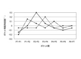
- FIG. FIG. 4 is a schematic diagram of both annular cages showing the difference in the equal pocket angle between pockets and the direction of the pockets. 4 is a graph showing equal pocket angular differences between pockets for three retainers of the present embodiment.
- FIG. 4 is a developed view of both ring-shaped cages for explaining variations in the bottom thickness of the pocket.
- FIG. 10 is a schematic diagram of both annular cages of a comparative example showing the equal pocket angle difference between pockets and the orientation of the pockets.
- 7 is a graph showing equal pocket angular differences between pockets for three cages as comparative examples. It is a graph which shows the relationship between roundness and rotation life time.
- 7 is a graph showing the relationship between the maximum value of the equal pocket angle difference between pockets, the number of deviations in pocket orientation, and the rotation life time.
- 7 is a graph showing the relationship between the maximum pocket orientation angle and the rotation life time.
- it is a perspective view of a crown-shaped retainer.
- the deep groove ball bearing 10 of this embodiment includes an outer ring 20 having an outer ring raceway groove 21 formed on its inner peripheral surface, an inner ring 30 having an inner ring raceway groove 31 formed on its outer peripheral surface, and an outer ring raceway.
- a resin retainer having a plurality of balls 11 rotatably disposed between the groove 21 and the inner ring raceway groove 31, and a plurality of cylindrical pockets P (see FIG. 2) for rotatably retaining the balls 11 respectively.
- a double ring-shaped retainer 40 that is a container.
- both ring-shaped retainers 40 are composed of a pair of ring portions 41 that are arranged to face each other in the axial direction, and a pair of ring portions 41 extending in the axial direction. 41, and a plurality of (seven in the embodiment shown in FIG. 10) pillars 42 arranged at equal intervals in the circumferential direction, and the pocket P includes the adjacent pillars 42 and a pair of annular rings. 41.
- Both annular retainers 40 are of an outer ring guide type, and the outer peripheral surfaces 46 of the pair of annular portions 41 are guided by the inner peripheral surface 22 of the shoulder portion of the outer ring 20 .
- Both annular retainers 40 may be manufactured by cutting or may be manufactured by injection molding.
- Examples of the resin material of the both ring-shaped retainers 40 include polyamide resins such as 46 nylon and 66 nylon, polybutylene terephthalate, polyphenylene sulfide (PPS), polyetheretherketone (PEEK), and polyethernitrile (PEN). , polyethylene terephthalate (PET), etc., to which 10 to 50 wt % of reinforcing fiber material (for example, glass fiber or carbon fiber) is added.
- polyamide resins such as 46 nylon and 66 nylon
- PPS polyphenylene sulfide
- PEEK polyetheretherketone
- PEN polyethernitrile
- PET polyethylene terephthalate
- reinforcing fiber material for example, glass fiber or carbon fiber
- the double ring-shaped retainer 40 of the present embodiment is designed to reduce vibration of the retainer 40 during rotation of the bearing even when used under high-speed rotation conditions of dmn 1,000,000 or more, thereby improving the life of the bearing.
- all of the following conditions (i) to (iii) are satisfied, and preferably at least one condition of (iv) to (vi) is further satisfied.
- the circularity of the outer peripheral surface 46 which is the guide surface, is 5 ⁇ m or less.
- the difference between the angle between the centers C of adjacent pockets P and 360°/the number of pockets (herein also referred to as the "equally arranged pocket angle difference between pockets P") is ⁇ within 0.1°.
- the direction of the center C of all the pockets P is toward one side in the circumferential direction and one side in the axial direction as it goes from the outer diameter side to the inner diameter side.
- the orientation of the centers C of all pockets P is within 1°.
- the total difference between the angle between the centers C of adjacent pockets P on both sides and 360°/the number of pockets is within ⁇ 0.1°.
- Variation in the bottom thickness T of each pocket P (that is, the minimum distance between the side surface on one axial side of the retainer 40 and each pocket P) is within 10 ⁇ m (see FIG. 7).
- the center C of the pocket P is, in terms of design, directed from the outer diameter side to the inner diameter side, as indicated by the two-dot chain line in FIG. It is designed so that it intersects and the axial position does not change over the radial direction. That is, on a plane that passes through the rotation axis center X and is perpendicular to the center C of the designed pocket P, the rotation axis center X is defined as the first axis L1, and the rotation axis passes through the center C in the axial direction.
- the center C of the pocket P passes through the intersection point XA between the first axis L1 and the second axis L2. is projected as a pocket P'.
- the pocket P is projected as a pocket P' indicated by a dotted line on a plane containing the first axis L1 and the second axis L2. That is, as shown in FIGS. 4(a) to 4(d), with the outer diameter side opening of the pocket P as a reference, the direction of the center C of the pocket P is 4 degrees with the first axis L1 and the second axis L2 as boundaries. It is formed staggered toward one of the three regions A1 to A4. On the other hand, in this embodiment, the pockets P are formed so that the centers C of all the pockets P face one of the four regions A1 to A4.
- the directions of the centers C of all the pockets P are the intersection point XA between the first axis L1 and the second axis L2 and the center position of the ball 11 (the center C of the pocket P and the center C of the ball 11
- the position where the pitch circle diameter intersects) C1 is intersected within 1°. That is, in FIG. 3, the orientation of the center C of the pocket P in design (the axis of the center C) indicated by the two-dot chain line and the orientation of the center C of the pocket P (the axis of the center C) indicated by the one-dot chain line.
- the angle formed by the axes of these two centers C on a plane containing the center C is within 1°.
- the direction of C is varied so as to face the region A2 in which the circumferential direction is positive and the axial direction is negative.
- the pockets P1 to P7 are arranged such that the direction of the center C of all the pockets P1 to P7 is the region A1 in which the circumferential direction is positive and the axial direction is positive. is formed.
- the condition (ii) in the case of the general cage which is a comparative example, as in the three examples shown in FIG. At some position, the range of ⁇ 0.1 is exceeded.
- the equal pocket angle difference between the pockets P7-P1 to P6-P7 is within the range of ⁇ 0.1 at any position. It is formed to be In the graphs of FIGS. 6 and 9, the dashed line corresponds to the equal pocket angular difference between the pockets P7-P1 to P6-7 in the retainer shown in FIGS.
- FIG. 10 shows the test results when the roundness of the guide surface was changed with respect to condition (i) in a retainer that satisfies conditions (ii) to (vi). As can be seen from this result, if the roundness of the guide surface is 5 ⁇ m or less, any cage can be used without breakage up to a predetermined rotation life time (400 hours).
- FIG. 11 shows a cage that satisfies the conditions (i), (iv), and (vi), with respect to the condition (ii), by changing the maximum value of the equal pocket angular difference between the pockets, and Regarding (iii), the test results are shown when the number of shifts in the pocket direction is changed.
- the circularity of the guide surface is 5 ⁇ m or less
- the maximum value of the equal pocket angle difference between the pockets is ⁇ 0.1° or less
- all the pockets are oriented in the circumferential direction. If it is directed to either side, or to either side in the axial direction, the cage can be used without breakage up to a predetermined rotation life time (1000 hours).
- FIG. 12 shows the case where the maximum value of the direction of the center C of all pockets P is changed with respect to condition (iv) while satisfying conditions (i) to (iii), (v), and (vi). shows the test results of As can be seen from this result, if the maximum value of the directions of the centers C of all the pockets P is within 1°, a rotational life of 1000 hours or longer can be obtained.
- condition (v) for any given pocket P, the sum of the differences between the angle between the centers of adjacent pockets P on both sides and 360°/the number of pockets must be within ⁇ 0.1°. By doing so, it is possible to further extend the rotational life of the retainer without breakage.
- the circularity of the guide surface is 5 ⁇ m or less, and the difference between the angle between the centers of adjacent pockets and the number of pockets is 360°/the number of pockets. , Both are within ⁇ 0.1°, and the direction of the center of all the pockets is toward one side in the circumferential direction and one side in the axial direction from the outer diameter side to the inner diameter side.
- the present invention is not limited to the above-described embodiments, and can be modified, improved, etc. as appropriate.
- the deep groove ball bearing was described as the ball bearing, but the ball bearing of the present invention may be an angular contact ball bearing. It should be noted that the applicant found that substantially the same test results were obtained when the above-described tests shown in FIGS. confirmed.
- both annular retainers are of the outer ring guide type, but may be of the inner ring guide type using the inner peripheral surface of the annular portion as the guide surface.
- a double ring type cage was explained as a cage, but as a cage of the present invention, a crown type cage 40A having a partially cylindrical pocket P as shown in FIG. 13 is used. There may be.
Landscapes
- Engineering & Computer Science (AREA)
- General Engineering & Computer Science (AREA)
- Mechanical Engineering (AREA)
- Rolling Contact Bearings (AREA)
Abstract
樹脂製保持器(40)は、少なくとも一つの円環部(41)と、円環部(41)から軸方向にそれぞれ延在する複数の柱部(42)と、を備え、隣り合う柱部(42)の間に形成される円筒状又は部分円筒状のポケット(P)で玉(11)を回転自在に保持し、円環部(41)は、外輪(20)の内周面又は内輪(30)の外周面によって案内される案内面を有する。案内面の真円度が、5μm以下であり、隣り合うポケットPの中心間の角度と、360°/ポケット数との差が、いずれも±0.1°以内であり、且つ、全てのポケットPの中心Cの向きは、外径側から内径側に向かうにつれて、周方向においていずれか一方側、軸方向においていずれか一方側に向かう。これにより、軸受回転時の保持器の振動を低減し、軸受寿命を向上できる。
Description
本発明は、玉軸受用樹脂製保持器及び玉軸受に関し、例えば、歯科エアタービン、クリーナ、電動工具など高速回転で使用される玉軸受用樹脂製保持器及び玉軸受に関する。
一般的に、玉軸受に適用される樹脂製保持器は、射出成形により製造される。具体的には、金型内に保持器に対応する環状のキャビティを形成し、このキャビティの周縁部に設けた樹脂射出ゲートから溶融された樹脂材料(熱可塑性樹脂)を注入し、冷却固化することによって保持器が製造される。
特許文献1では、樹脂製保持器として、球面形状のポケットを有する冠型保持器や、円筒形状のポケットを有する両円環型保持器が開示されている。また、特許文献2に記載のアンギュラ玉軸受では、円筒部と縮径部を組み合わせたポケットを有する樹脂製保持器が開示されている。
ところで、特許文献1及び2に記載のような樹脂製保持器では、各ポケットは円周方向に等配されると一般的に示されているが、実際には、各ポケット間の角度はばらつきが発生し、極わずかに等配が崩れている。
また、円筒形状のポケットの場合、各ポケットの中心も軸受の中心に向いていると一般的に示されているが、実際には、各ポケットの中心の向きがばらついた方向を向きながら軸受の中心に向かっている。
また、円筒形状のポケットの場合、各ポケットの中心も軸受の中心に向いていると一般的に示されているが、実際には、各ポケットの中心の向きがばらついた方向を向きながら軸受の中心に向かっている。
このため、上述したポケットの配置角度やポケットの向きにばらつきを有する樹脂製保持器が、例えば、dmn100万以上の高速回転で使用されると、保持器の振動が大きくなり、軸受寿命が短くなるという課題がある。
本発明は、前述した課題に鑑みてなされたものであり、その目的は、軸受回転時の保持器の振動を低減し、軸受寿命を向上できる玉軸受用樹脂製保持器及び玉軸受を提供することにある。
本発明の上記目的は、下記の構成により達成される。
[1] 少なくとも一つの円環部と、前記円環部から軸方向にそれぞれ延在する複数の柱部と、を備え、隣り合う前記柱部の間に形成される円筒状又は部分円筒状のポケットで玉軸受の玉を回転自在に保持可能で、前記円環部は、前記玉軸受の外輪の内周面又は内輪の外周面によって案内される案内面を有する玉軸受用樹脂製保持器であって、
前記案内面の真円度は、5μm以下であり、
隣り合う前記ポケットの中心間の角度と、360°/ポケット数との差は、いずれも±0.1°以内であり、
全ての前記ポケットの中心の向きは、外径側から内径側に向かうにつれて、周方向においていずれか一方側、軸方向においていずれか一方側に向かう、
玉軸受用樹脂製保持器。
[2] 任意の前記ポケットに対して、隣り合う両側の前記ポケットとの中心間の角度と、360°/ポケット数との差の合計は、±0.1°以内である、
[1]に記載の玉軸受用樹脂製保持器。
[3] 前記全てのポケットの中心の向きは、1°以内である、[1]または[2]に記載の玉軸受用樹脂製保持器。
[4] 前記各ポケットの底厚のばらつきは、10μm以内である、[1]~[3]のいずれかに記載の玉軸受。
[5] 前記樹脂製保持器は、冠型保持器、又は、一対の前記円環部を有する両円環型保持器である、[1]~[4]のいずれかに記載の玉軸受用樹脂製保持器。
[6] 内周面に外輪軌道溝が形成された外輪と、
外周面に内輪軌道溝が形成された内輪と、
前記外輪軌道溝と前記内輪軌道溝の間に転動自在に配設された複数の玉と、
[1]~[5]のいずれかに記載の玉軸受用樹脂製保持器と、
を備える玉軸受。
本発明の玉軸受用樹脂製保持器及び玉軸受によれば、案内面の真円度が、5μm以下であり、隣り合うポケットの中心間の角度と、360°/ポケット数との差が、いずれも±0.1°以内であり、且つ、全てのポケットの中心の向きは、外径側から内径側に向かうにつれて、周方向においていずれか一方側、軸方向においていずれか一方側に向かうことで、軸受回転時の保持器の振動を低減し、軸受寿命を向上できる。
以下、本発明の一実施形態に係る、玉軸受用樹脂製保持器、及び該樹脂製保持器が組み込まれた玉軸受を図面に基づいて詳細に説明する。
図1に示すように、本実施形態の深溝玉軸受10は、内周面に外輪軌道溝21が形成された外輪20と、外周面に内輪軌道溝31が形成された内輪30と、外輪軌道溝21と内輪軌道溝31の間に転動自在に配設された複数の玉11と、玉11をそれぞれ回転自在に保持する円筒状の複数のポケットP(図2参照)を有する樹脂製保持器である両円環型保持器40と、を備える。
図2に示すように、両円環型保持器40は、軸方向で対向配置された一対の円環部41と、一対の円環部41が軸方向に延在して一対の円環部41を接続し、円周方向に等間隔で配置された複数(図10に示す実施形態では7つ)の柱部42と、を備え、ポケットPは、隣り合う柱部42と一対の円環部41とで形成される。また、両円環型保持器40は、外輪案内方式であり、一対の円環部41における外周面46が、外輪20の肩部の内周面22に案内されている。
両円環型保持器40は、切削加工で製作されてもよいし、射出成形で製作されてもよい。
両円環型保持器40は、切削加工で製作されてもよいし、射出成形で製作されてもよい。
両円環型保持器40の樹脂材料としては、例えば、46ナイロンや66ナイロンなどのポリアミド系樹脂、ポリブチレンテレフタレート、ポリフェニレンサルファイド(PPS)、ポリエーテルエーテルケトン(PEEK)、ポリエーテルニトリル(PEN)、ポリエチレンテレフタレート(PET)等の合成樹脂に、10~50wt%の補強繊維材(例えば、ガラス繊維や炭素繊維)を添加した樹脂組成物が用いられる。
ここで、本実施形態の両円環型保持器40は、dmn100万以上の高速回転条件で使用される場合においても、軸受回転時の保持器40の振動を低減し、軸受寿命を向上できるように次の(i)~(iii)の全ての条件を満足する、好ましくは(iv)~(vi)の少なくとも一つの条件をさらに満足するように構成されている。
(i)案内面である外周面46の真円度は、5μm以下である。
(ii) 隣り合うポケットPの中心C間の角度と、360°/ポケット数との差(本明細書では、「各ポケットP間のポケット等配角度差」とも称す。)が、いずれも±0.1°以内である。
(iii)全てのポケットPの中心Cの向きは、外径側から内径側に向かうにつれて、周方向においていずれか一方側、軸方向においていずれか一方側に向かう。
(iv) 全てのポケットPの中心Cの向きは、1°以内である。
(v)任意のポケットPに対して、隣り合う両側のポケットPとの中心C間の角度と、360°/ポケット数との差の合計は、±0.1°以内である。
(vi) 各ポケットPの底厚T(即ち、保持器40の軸方向一方側の側面と各ポケットPとの最小距離)のばらつきは、10μm以内である(図7参照)。
条件(iii)に関して、ポケットPの中心Cは、設計上、図3の二点鎖線で示すように、外径側から内径側に向かい、玉軸受10の回転軸中心X(図1参照)と交差し、軸方向位置が径方向に亙って変わらないように設計される。
すなわち、回転軸中心Xを通過し、設計上のポケットPの中心Cに直交する平面上において、回転軸中心Xを第1軸L1とし、上記中心Cの軸方向位置を通過して、回転軸中心Xと直交する軸を第2軸L2としたとき、設計上のポケットPを外径側から投影すると、ポケットPの中心Cが、第1軸L1と第2軸L2との交点XAを通過するポケットP´として投影される。
すなわち、回転軸中心Xを通過し、設計上のポケットPの中心Cに直交する平面上において、回転軸中心Xを第1軸L1とし、上記中心Cの軸方向位置を通過して、回転軸中心Xと直交する軸を第2軸L2としたとき、設計上のポケットPを外径側から投影すると、ポケットPの中心Cが、第1軸L1と第2軸L2との交点XAを通過するポケットP´として投影される。
しかしながら、一般的な保持器では、ポケットPの中心Cの向きは、図3の一点鎖線で示すように、外径側から内径側に向かうにつれて、厳密には、上述した第1軸L1及び第2軸L2との交点XAから外れ、ポケットPは、第1軸L1及び第2軸L2を含む平面上で、点線で示すポケットP´として投影される。即ち、図4(a)~(d)に示すように、ポケットPの外径側開口を基準として、ポケットPの中心Cの向きは、第1軸L1及び第2軸L2を境とした4つの領域A1~A4のいずれかに向かってばらついて形成される。
一方、本実施形態では、全てのポケットPの中心Cの向きが、4つの領域A1~A4のいずれか1つに向かうように、ポケットPを形成する。
一方、本実施形態では、全てのポケットPの中心Cの向きが、4つの領域A1~A4のいずれか1つに向かうように、ポケットPを形成する。
また、条件(iv)に関しては、全てのポケットPの中心Cの向きが、第1軸L1及び第2軸L2との交点XAと、玉11の中心位置(ポケットPの中心Cと玉11のピッチ円径が交わる位置)C1とを結ぶ直線に対して、1°以内で交差することを表している。
即ち、図3において、二点鎖線で示す、設計上のポケットPの中心Cの向き(中心Cの軸線)と、一点鎖線で示す、ポケットPの中心Cの向き(中心Cの軸線)とを含む平面において、これら2本の中心Cの軸線がなす角度が、1°以内となる。
即ち、図3において、二点鎖線で示す、設計上のポケットPの中心Cの向き(中心Cの軸線)と、一点鎖線で示す、ポケットPの中心Cの向き(中心Cの軸線)とを含む平面において、これら2本の中心Cの軸線がなす角度が、1°以内となる。
例えば、図2に示す、7つのポケットP(P1~P7)を有する両円環型保持器40において、比較例である一般的な保持器では、図8に示すように、ポケットP1,P3,P7の中心Cの向きが、周方向が-、軸方向が-の領域A3、ポケットP2,P5,P6の中心Cの向きが周方向が+、軸方向が+の領域A1、ポケットP4の中心Cの向きが周方向が+、軸方向が-の領域A2に向かうようにばらついて形成される。
一方、本実施形態の保持器では、図5に示すように、全てのポケットP1~P7の中心Cの向きが、周方向が+、軸方向が+の領域A1となるようにポケットP1~P7が形成されている。
一方、本実施形態の保持器では、図5に示すように、全てのポケットP1~P7の中心Cの向きが、周方向が+、軸方向が+の領域A1となるようにポケットP1~P7が形成されている。
また、条件(ii)に関しては、比較例である一般的な保持器では、図9に示す3つの例のように、各ポケット間P7-P1~P6-P7のポケット等配角度差は、いずれかの位置で、±0.1の範囲を越えている。
一方、本実施形態では、図6に示す3つの例のように、各ポケット間P7-P1~P6-P7のポケット等配角度差は、いずれかの位置においても±0.1の範囲内となるように形成されている。
なお、図6及び図9のグラフにおいて、一点鎖線は、図5及び図8に示された保持器における各ポケット間P7-P1~P6-7のポケット等配角度差に対応している。
一方、本実施形態では、図6に示す3つの例のように、各ポケット間P7-P1~P6-P7のポケット等配角度差は、いずれかの位置においても±0.1の範囲内となるように形成されている。
なお、図6及び図9のグラフにおいて、一点鎖線は、図5及び図8に示された保持器における各ポケット間P7-P1~P6-7のポケット等配角度差に対応している。
次に、条件(i)~(iv)に関して、歯科エアタービンに評価軸受を組み込み、次の試験条件で、回転寿命時間に関する試験を行った。
(試験条件)
・使用軸受寸法:内径φ3.175mm×外径φ6.35mm×幅2.38mm
・回転数:40万回転
・軸受予圧:5N(±1N)
・寿命判定基準:初期40万回転が36万回転に低下した時点を寿命とした。
・使用軸受寸法:内径φ3.175mm×外径φ6.35mm×幅2.38mm
・回転数:40万回転
・軸受予圧:5N(±1N)
・寿命判定基準:初期40万回転が36万回転に低下した時点を寿命とした。
図10は、条件(ii)~(vi)を満足する保持器において、条件(i)に関して、案内面の真円度を変更した場合の試験結果を示している。この結果からわかるように、案内面の真円度が5μm以下であれば、いずれの保持器においても所定の回転寿命時間(400時間)まで保持器は破断することなく、使用することができる。
また、図11は、条件(i)、(iv)、(vi)を満足する保持器において、条件(ii)に関して、各ポケット間のポケット等配角度差の最大値を変更し、且つ、条件(iii)に関して、ポケット向きズレ数を変更した場合の試験結果を示している。この結果からわかるように、案内面の真円度が5μm以下で、各ポケット間のポケット等配角度差の最大値が±0.1°以下で、且つ、全てのポケットの向きが周方向においていずれか一方側、軸方向においていずれか一方側に向かう場合には、所定の回転寿命時間(1000時間)まで保持器は破断することなく、使用することができる。
さらに、図12は、条件(i)~(iii)、(v)、(vi)を満足する状態で、条件(iv)に関して、全てのポケットPの中心Cの向きの最大値を変更した場合の試験結果を示している。この結果からわかるように、全てのポケットPの中心Cの向きの最大値が1°以内であれば、1000時間以上の回転寿命時間が得られることがわかる。
なお、条件(v)に関しても、任意のポケットPに対して、隣り合う両側のポケットPとの中心間の角度と、360°/ポケット数との差の合計が、±0.1°以内であることで、保持器は破断することなく、回転寿命をさらに延ばすことができる。
同様に、条件(vi)に関しても、各ポケットPの底厚Tのばらつきは、10μm以内であることで、保持器は破断することなく、回転寿命をさらに延ばすことができ、また、良好な音響性能を確保することができる。
以上説明したように、本実施形態の深溝玉軸受10によれば、案内面の真円度が、5μm以下であり、隣り合うポケットの中心間の角度と、360°/ポケット数との差が、いずれも±0.1°以内であり、且つ、全てのポケットの中心の向きは、外径側から内径側に向かうにつれて、周方向においていずれか一方側、軸方向においていずれか一方側に向かうことで、軸受回転時の保持器の振動を低減し、軸受寿命を向上できる。
尚、本発明は、前述した各実施形態に限定されるものではなく、適宜、変形、改良、等が可能である。
上記実施形態では、玉軸受として深溝玉軸受について説明したが、本発明の玉軸受としては、アンギュラ玉軸受であってもよい。
なお、出願人は、上記両円環型保持器が組み込まれたアンギュラ玉軸受を用いて、上述した図10~図12の試験を行ったところ、実質的に同様な試験結果が得られることを確認した。
上記実施形態では、玉軸受として深溝玉軸受について説明したが、本発明の玉軸受としては、アンギュラ玉軸受であってもよい。
なお、出願人は、上記両円環型保持器が組み込まれたアンギュラ玉軸受を用いて、上述した図10~図12の試験を行ったところ、実質的に同様な試験結果が得られることを確認した。
また、上記実施形態では、両円環型保持器は、外輪案内方式としているが、円環部の内周面を案内面とした内輪案内方式としてもよい。
また、上記実施形態では、保持器として両円環型保持器について説明したが、本発明の保持器としては、図13に示すような、部分円筒状のポケットPを有する冠型保持器40Aであってもよい。
また、上記実施形態では、保持器として両円環型保持器について説明したが、本発明の保持器としては、図13に示すような、部分円筒状のポケットPを有する冠型保持器40Aであってもよい。
なお、本出願は、2022年2月14日出願の日本特許出願(特願2022-020600)に基づくものであり、その内容は本出願の中に参照として援用される。
10 深溝玉軸受(玉軸受)
11 玉
40 両円環型保持器(樹脂製保持器)
40A 冠型保持器(樹脂製保持器)
41 円環部
42 柱部
46 外周面(案内面)
A1~A4 領域
P,P1~P7 ポケット
11 玉
40 両円環型保持器(樹脂製保持器)
40A 冠型保持器(樹脂製保持器)
41 円環部
42 柱部
46 外周面(案内面)
A1~A4 領域
P,P1~P7 ポケット
Claims (6)
- 少なくとも一つの円環部と、前記円環部から軸方向にそれぞれ延在する複数の柱部と、を備え、隣り合う前記柱部の間に形成される円筒状又は部分円筒状のポケットで玉軸受の玉を回転自在に保持可能で、前記円環部は、前記玉軸受の外輪の内周面又は内輪の外周面によって案内される案内面を有する、玉軸受用樹脂製保持器であって、
前記案内面の真円度は、5μm以下であり、
隣り合う前記ポケットの中心間の角度と、360°/ポケット数との差は、いずれも±0.1°以内であり、
全ての前記ポケットの中心の向きは、外径側から内径側に向かうにつれて、周方向においていずれか一方側、軸方向においていずれか一方側に向かう、
玉軸受用樹脂製保持器。 - 任意の前記ポケットに対して、隣り合う両側の前記ポケットとの中心間の角度と、360°/ポケット数との差の合計は、±0.1°以内である、
請求項1に記載の玉軸受用樹脂製保持器。 - 前記全てのポケットの中心の向きは、1°以内である、請求項1または2に記載の玉軸受用樹脂製保持器。
- 前記各ポケットの底厚のばらつきは、10μm以内である、請求項1~3のいずれか1項に記載の玉軸受用樹脂製保持器。
- 前記樹脂製保持器は、冠型保持器、又は、一対の前記円環部を有する両円環型保持器である、請求項1~4のいずれか1項に記載の玉軸受用樹脂製保持器。
- 内周面に外輪軌道溝が形成された外輪と、
外周面に内輪軌道溝が形成された内輪と、
前記外輪軌道溝と前記内輪軌道溝の間に転動自在に配設された複数の玉と、
請求項1~5のいずれか1項に記載の玉軸受用樹脂製保持器と、
を備える玉軸受。
Applications Claiming Priority (2)
| Application Number | Priority Date | Filing Date | Title |
|---|---|---|---|
| JP2022-020600 | 2022-02-14 | ||
| JP2022020600 | 2022-02-14 |
Publications (1)
| Publication Number | Publication Date |
|---|---|
| WO2023153412A1 true WO2023153412A1 (ja) | 2023-08-17 |
Family
ID=87564378
Family Applications (1)
| Application Number | Title | Priority Date | Filing Date |
|---|---|---|---|
| PCT/JP2023/004068 WO2023153412A1 (ja) | 2022-02-14 | 2023-02-07 | 玉軸受用樹脂製保持器及び玉軸受 |
Country Status (1)
| Country | Link |
|---|---|
| WO (1) | WO2023153412A1 (ja) |
Citations (3)
| Publication number | Priority date | Publication date | Assignee | Title |
|---|---|---|---|---|
| WO1999001676A1 (fr) * | 1997-07-01 | 1999-01-14 | Koyo Seiko Co., Ltd. | Bague de roulement en resine synthetique, procede de fabrication de cette bague et roulement a rouleaux |
| JP2008256152A (ja) * | 2007-04-06 | 2008-10-23 | Nsk Ltd | 歯科用ハンドピース用の転がり軸受 |
| CN107676386A (zh) * | 2017-11-21 | 2018-02-09 | 进发轴承有限公司 | 一种轴承保持架 |
-
2023
- 2023-02-07 WO PCT/JP2023/004068 patent/WO2023153412A1/ja unknown
Patent Citations (3)
| Publication number | Priority date | Publication date | Assignee | Title |
|---|---|---|---|---|
| WO1999001676A1 (fr) * | 1997-07-01 | 1999-01-14 | Koyo Seiko Co., Ltd. | Bague de roulement en resine synthetique, procede de fabrication de cette bague et roulement a rouleaux |
| JP2008256152A (ja) * | 2007-04-06 | 2008-10-23 | Nsk Ltd | 歯科用ハンドピース用の転がり軸受 |
| CN107676386A (zh) * | 2017-11-21 | 2018-02-09 | 进发轴承有限公司 | 一种轴承保持架 |
Similar Documents
| Publication | Publication Date | Title |
|---|---|---|
| CN108397476B (zh) | 滚珠轴承 | |
| JP6922928B2 (ja) | 転がり軸受用保持器、及び転がり軸受 | |
| US11255381B2 (en) | Rolling bearing and cage | |
| EP4116593A1 (en) | Crown-shaped retainer for ball bearing and ball bearing | |
| US11274701B2 (en) | Rolling bearing and cage | |
| WO2015141812A1 (ja) | アンギュラ玉軸受 | |
| US20220099142A1 (en) | Ball bearing | |
| US7044645B2 (en) | Retainer with rotationally symmetric pockets | |
| WO2023153412A1 (ja) | 玉軸受用樹脂製保持器及び玉軸受 | |
| US10663001B2 (en) | Ball bearing cage | |
| WO2015129064A1 (ja) | アンギュラ玉軸受 | |
| WO2015146811A1 (ja) | アンギュラ玉軸受 | |
| JP6529209B2 (ja) | アンギュラ玉軸受 | |
| JP7314701B2 (ja) | 深溝玉軸受 | |
| JP2013036608A (ja) | 冠形保持器及び転がり軸受 | |
| WO2023181352A1 (ja) | 転がり軸受、及び、転がり軸受用の保持器 | |
| CN213954169U (zh) | 滚珠轴承 | |
| WO2023195299A1 (ja) | 玉軸受用樹脂製保持器、玉軸受、及び玉軸受用樹脂製保持器の製造方法 | |
| JP2022146662A (ja) | 軸受 | |
| WO2019146768A1 (ja) | アンギュラ玉軸受 | |
| JP2006017180A (ja) | 合成樹脂製の冠形保持器 | |
| US20240052881A1 (en) | Ball bearing | |
| WO2023112625A1 (ja) | 転がり軸受 | |
| JP2021195973A (ja) | 玉軸受 | |
| WO2024047920A1 (ja) | 冠型保持器及び玉軸受 |
Legal Events
| Date | Code | Title | Description |
|---|---|---|---|
| 121 | Ep: the epo has been informed by wipo that ep was designated in this application |
Ref document number: 23752876 Country of ref document: EP Kind code of ref document: A1 |