WO2023153145A1 - ランプユニットおよび車両用灯具 - Google Patents
ランプユニットおよび車両用灯具 Download PDFInfo
- Publication number
- WO2023153145A1 WO2023153145A1 PCT/JP2023/001011 JP2023001011W WO2023153145A1 WO 2023153145 A1 WO2023153145 A1 WO 2023153145A1 JP 2023001011 W JP2023001011 W JP 2023001011W WO 2023153145 A1 WO2023153145 A1 WO 2023153145A1
- Authority
- WO
- WIPO (PCT)
- Prior art keywords
- lamp unit
- fan
- duct
- heat sink
- unit according
- Prior art date
- Legal status (The legal status is an assumption and is not a legal conclusion. Google has not performed a legal analysis and makes no representation as to the accuracy of the status listed.)
- Ceased
Links
Images



Classifications
-
- F—MECHANICAL ENGINEERING; LIGHTING; HEATING; WEAPONS; BLASTING
- F21—LIGHTING
- F21S—NON-PORTABLE LIGHTING DEVICES; SYSTEMS THEREOF; VEHICLE LIGHTING DEVICES SPECIALLY ADAPTED FOR VEHICLE EXTERIORS
- F21S41/00—Illuminating devices specially adapted for vehicle exteriors, e.g. headlamps
- F21S41/10—Illuminating devices specially adapted for vehicle exteriors, e.g. headlamps characterised by the light source
- F21S41/14—Illuminating devices specially adapted for vehicle exteriors, e.g. headlamps characterised by the light source characterised by the type of light source
- F21S41/141—Light emitting diodes [LED]
- F21S41/143—Light emitting diodes [LED] the main emission direction of the LED being parallel to the optical axis of the illuminating device
- F21S41/145—Light emitting diodes [LED] the main emission direction of the LED being parallel to the optical axis of the illuminating device the main emission direction of the LED being opposite to the main emission direction of the illuminating device
-
- F—MECHANICAL ENGINEERING; LIGHTING; HEATING; WEAPONS; BLASTING
- F21—LIGHTING
- F21S—NON-PORTABLE LIGHTING DEVICES; SYSTEMS THEREOF; VEHICLE LIGHTING DEVICES SPECIALLY ADAPTED FOR VEHICLE EXTERIORS
- F21S41/00—Illuminating devices specially adapted for vehicle exteriors, e.g. headlamps
- F21S41/30—Illuminating devices specially adapted for vehicle exteriors, e.g. headlamps characterised by reflectors
- F21S41/32—Optical layout thereof
- F21S41/33—Multi-surface reflectors, e.g. reflectors with facets or reflectors with portions of different curvature
-
- F—MECHANICAL ENGINEERING; LIGHTING; HEATING; WEAPONS; BLASTING
- F21—LIGHTING
- F21S—NON-PORTABLE LIGHTING DEVICES; SYSTEMS THEREOF; VEHICLE LIGHTING DEVICES SPECIALLY ADAPTED FOR VEHICLE EXTERIORS
- F21S41/00—Illuminating devices specially adapted for vehicle exteriors, e.g. headlamps
- F21S41/60—Illuminating devices specially adapted for vehicle exteriors, e.g. headlamps characterised by a variable light distribution
-
- F—MECHANICAL ENGINEERING; LIGHTING; HEATING; WEAPONS; BLASTING
- F21—LIGHTING
- F21S—NON-PORTABLE LIGHTING DEVICES; SYSTEMS THEREOF; VEHICLE LIGHTING DEVICES SPECIALLY ADAPTED FOR VEHICLE EXTERIORS
- F21S45/00—Arrangements within vehicle lighting devices specially adapted for vehicle exteriors, for purposes other than emission or distribution of light
- F21S45/40—Cooling of lighting devices
- F21S45/42—Forced cooling
- F21S45/43—Forced cooling using gas
- F21S45/435—Forced cooling using gas circulating the gas within a closed system
-
- F—MECHANICAL ENGINEERING; LIGHTING; HEATING; WEAPONS; BLASTING
- F21—LIGHTING
- F21V—FUNCTIONAL FEATURES OR DETAILS OF LIGHTING DEVICES OR SYSTEMS THEREOF; STRUCTURAL COMBINATIONS OF LIGHTING DEVICES WITH OTHER ARTICLES, NOT OTHERWISE PROVIDED FOR
- F21V29/00—Protecting lighting devices from thermal damage; Cooling or heating arrangements specially adapted for lighting devices or systems
- F21V29/50—Cooling arrangements
- F21V29/502—Cooling arrangements characterised by the adaptation for cooling of specific components
- F21V29/503—Cooling arrangements characterised by the adaptation for cooling of specific components of light sources
-
- F—MECHANICAL ENGINEERING; LIGHTING; HEATING; WEAPONS; BLASTING
- F21—LIGHTING
- F21V—FUNCTIONAL FEATURES OR DETAILS OF LIGHTING DEVICES OR SYSTEMS THEREOF; STRUCTURAL COMBINATIONS OF LIGHTING DEVICES WITH OTHER ARTICLES, NOT OTHERWISE PROVIDED FOR
- F21V29/00—Protecting lighting devices from thermal damage; Cooling or heating arrangements specially adapted for lighting devices or systems
- F21V29/50—Cooling arrangements
- F21V29/502—Cooling arrangements characterised by the adaptation for cooling of specific components
- F21V29/508—Cooling arrangements characterised by the adaptation for cooling of specific components of electrical circuits
-
- F—MECHANICAL ENGINEERING; LIGHTING; HEATING; WEAPONS; BLASTING
- F21—LIGHTING
- F21V—FUNCTIONAL FEATURES OR DETAILS OF LIGHTING DEVICES OR SYSTEMS THEREOF; STRUCTURAL COMBINATIONS OF LIGHTING DEVICES WITH OTHER ARTICLES, NOT OTHERWISE PROVIDED FOR
- F21V29/00—Protecting lighting devices from thermal damage; Cooling or heating arrangements specially adapted for lighting devices or systems
- F21V29/50—Cooling arrangements
- F21V29/60—Cooling arrangements characterised by the use of a forced flow of gas, e.g. air
- F21V29/65—Cooling arrangements characterised by the use of a forced flow of gas, e.g. air the gas flowing in a closed circuit
-
- F—MECHANICAL ENGINEERING; LIGHTING; HEATING; WEAPONS; BLASTING
- F21—LIGHTING
- F21V—FUNCTIONAL FEATURES OR DETAILS OF LIGHTING DEVICES OR SYSTEMS THEREOF; STRUCTURAL COMBINATIONS OF LIGHTING DEVICES WITH OTHER ARTICLES, NOT OTHERWISE PROVIDED FOR
- F21V29/00—Protecting lighting devices from thermal damage; Cooling or heating arrangements specially adapted for lighting devices or systems
- F21V29/50—Cooling arrangements
- F21V29/60—Cooling arrangements characterised by the use of a forced flow of gas, e.g. air
- F21V29/67—Cooling arrangements characterised by the use of a forced flow of gas, e.g. air characterised by the arrangement of fans
-
- F—MECHANICAL ENGINEERING; LIGHTING; HEATING; WEAPONS; BLASTING
- F21—LIGHTING
- F21V—FUNCTIONAL FEATURES OR DETAILS OF LIGHTING DEVICES OR SYSTEMS THEREOF; STRUCTURAL COMBINATIONS OF LIGHTING DEVICES WITH OTHER ARTICLES, NOT OTHERWISE PROVIDED FOR
- F21V29/00—Protecting lighting devices from thermal damage; Cooling or heating arrangements specially adapted for lighting devices or systems
- F21V29/50—Cooling arrangements
- F21V29/70—Cooling arrangements characterised by passive heat-dissipating elements, e.g. heat-sinks
- F21V29/74—Cooling arrangements characterised by passive heat-dissipating elements, e.g. heat-sinks with fins or blades
- F21V29/76—Cooling arrangements characterised by passive heat-dissipating elements, e.g. heat-sinks with fins or blades with essentially identical parallel planar fins or blades, e.g. with comb-like cross-section
-
- F—MECHANICAL ENGINEERING; LIGHTING; HEATING; WEAPONS; BLASTING
- F21—LIGHTING
- F21W—INDEXING SCHEME ASSOCIATED WITH SUBCLASSES F21K, F21L, F21S and F21V, RELATING TO USES OR APPLICATIONS OF LIGHTING DEVICES OR SYSTEMS
- F21W2102/00—Exterior vehicle lighting devices for illuminating purposes
-
- F—MECHANICAL ENGINEERING; LIGHTING; HEATING; WEAPONS; BLASTING
- F21—LIGHTING
- F21Y—INDEXING SCHEME ASSOCIATED WITH SUBCLASSES F21K, F21L, F21S and F21V, RELATING TO THE FORM OR THE KIND OF THE LIGHT SOURCES OR OF THE COLOUR OF THE LIGHT EMITTED
- F21Y2115/00—Light-generating elements of semiconductor light sources
- F21Y2115/10—Light-emitting diodes [LED]
-
- F—MECHANICAL ENGINEERING; LIGHTING; HEATING; WEAPONS; BLASTING
- F21—LIGHTING
- F21Y—INDEXING SCHEME ASSOCIATED WITH SUBCLASSES F21K, F21L, F21S and F21V, RELATING TO THE FORM OR THE KIND OF THE LIGHT SOURCES OR OF THE COLOUR OF THE LIGHT EMITTED
- F21Y2115/00—Light-generating elements of semiconductor light sources
- F21Y2115/30—Semiconductor lasers
Definitions
- the present disclosure relates to lamp units and vehicle lamps.
- Patent Document 1 discloses a lamp unit that performs illumination by scanning reflected light with a rotating reflector that reflects light emitted from a light source while rotating a light reflecting blade.
- the rotation of the fan provided in the lamp unit sends air to the heat sink through the duct, thereby cooling the light source, circuit board, and other cooling objects provided in the lamp unit.
- ducts are often designed for each lamp unit.
- every time the design of the heat sink is changed it is necessary to change the design of the duct according to the design change of the heat sink.
- An object of the present disclosure is to provide a lamp unit and a vehicle lamp that are easy to adapt to design changes of the heat sink.
- a lamp unit includes: a light source that emits light; a rotating mirror including at least one light reflecting blade for reflecting light emitted from the light source; a motor for rotating the rotating mirror; a fan driven by the motor to generate an airflow; a heat sink for dissipating heat generated by the light source; a flexible duct configured to guide the airflow from the fan to the heat sink.
- the bendable duct provided in the lamp unit guides the air flow from the fan to the heat sink, so the duct can be arranged relatively freely without depending on the positional relationship between the fan and the heat sink. can. Therefore, according to the lamp unit having the above configuration, it is possible to provide a lamp unit that can be easily adapted to changes in the design of the heat sink.
- a vehicle lamp includes: the above lamp unit; a common carrier supporting the lamp unit and an electronic device that produces heat different from the lamp unit; The fan also drives air to the electronic device as the fan rotates.
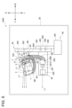
- FIG. 1 is a schematic diagram of a vehicle lamp according to the first embodiment.
- FIG. 2 is a diagram illustrating the first lamp unit according to the first embodiment.
- 3 is an enlarged view of the X portion of FIG. 2.
- FIG. 4 is a perspective view of the first lamp unit according to the first embodiment.
- FIG. 5 is a schematic diagram of a vehicle lamp according to a second embodiment. 6 is an enlarged view of the Y portion of FIG. 5.
- FIG. FIG. 7 is a diagram illustrating a fan according to a modification of the second embodiment.
- the terms “horizontal direction”, “vertical direction”, and “front-back direction” may be referred to as appropriate. These directions are relative directions set for the vehicle lamp 100 illustrated in FIG. 1 (hereinafter also referred to as the lamp 100) or the vehicle lamp 100A illustrated in FIG. 5 (hereinafter also referred to as the lamp 100A). is the direction.
- the “horizontal direction” is a direction including “leftward direction” and “rightward direction”.
- the “vertical direction” is a direction that includes the “upward direction” and the “downward direction”.
- Form-and-aft direction is a direction that includes "forward direction” and "rearward direction.”
- the front-rear direction is a direction perpendicular to the left-right direction and the up-down direction.
- symbol U shown in each drawing indicates an upward direction.
- Symbol D indicates the downward direction.
- Symbol F indicates the forward direction.
- Symbol B indicates the rearward direction.
- Symbol L indicates the left direction.
- the symbol R indicates the right direction.
- FIG. 1 is a schematic diagram of a vehicle lamp 100 according to this embodiment.
- the vehicle lamp 100 includes a first lamp unit 10 , a second lamp unit 20 , a carrier 30 , a leveling mechanism 40 and a housing 50 .
- the first lamp unit 10 , the second lamp unit 20 , the carrier 30 and the leveling mechanism 40 are housed within the housing 50 .
- the first lamp unit 10 is, for example, a scan-type lamp unit that can be mounted on a vehicle.
- the first lamp unit 10 has an ADB function (Adaptive Driving Beam) that changes the light distribution pattern according to the surrounding conditions and driving conditions of the vehicle.
- the first lamp unit 10 is configured to form a desired light distribution pattern and emit light forward of the vehicle.
- the first lamp unit 10 includes a light source 1, a projection lens 2, a rotating mirror 3, a motor 4, a substrate 5, a fan 6, a heat sink 7, and a duct 8. Prepare.
- the second lamp unit 20 is a lamp unit different from the first lamp unit 10.
- the second lamp unit 20 is positioned to the left of the first lamp unit 10 .
- the second lamp unit 20 may be positioned to the right of, above, or below the first lamp unit 10 .
- the second lamp unit 20 forms a light distribution pattern different from that of the first lamp unit 10 .
- the second lamp unit 20 includes an electronic device 201, a projection lens 202, and a heat sink 203.
- the electronic device 201 is a light emitting device with a light source 201A.
- the light source 201A is configured by, for example, an LED (Light Emitting Diode) element or an LD (Laser Diode) element.
- the light source 201A is arranged inside the electronic device 201 .
- the light source 201A is arranged behind the projection lens 202 .
- the light source 201A is arranged near the front of the heat sink 203 . Note that the light source 201A may or may not be in contact with the heat sink 203 .
- Light source 201A emits light toward projection lens 202 .
- the electronic device 201 is a device that electronically controls the light source 201A. When the electronic device 201 operates, heat is inevitably generated.
- the projection lens 202 is made of, for example, a translucent material such as transparent resin such as acrylic.
- the projection lens 202 is configured to project the light emitted from the light source 201 A forward of the second lamp unit 20 .
- the heat sink 203 is made of, for example, a metal material with high thermal conductivity such as aluminum or a resin material containing a filler such as talc.
- the heat sink 203 is configured to dissipate heat generated by the electronic device 201 .
- the carrier 30 is a plate-shaped member made of metal or resin to which various parts and/or devices can be attached.
- the carrier 30 is configured to support the first lamp unit 10 and the second lamp unit 20 .
- the carrier 30 has a base 301 and an insertion hole 302 . Note that, in this embodiment, the carrier 30 has four insertion holes 302 . However, the number of insertion holes 302 provided in the carrier 30 is not limited to this.
- the base 301 is equipped with a control circuit (not shown).
- An insertion hole 302 is provided in the base 301 .
- the insertion hole 302 is a substantially cylindrical hole extending in the lateral direction of the carrier 30 (the front-rear direction in FIG. 1).
- the shape of the insertion hole 302 is not limited to a substantially cylindrical shape.
- the shape of the insertion hole 302 may be, for example, a substantially quadrangular prism shape.
- the leveling mechanism 40 includes a motor 401, a bracket 402 and a screw 403.
- Motor 401 is, for example, a brushless DC motor.
- the motor 401 can move the bracket 402 by a rotational force generated by driving the motor 401 .
- the bracket 402 is made of a high-strength material such as glass fiber resin. Bracket 402 is, for example, a plate-like member. Bracket 402 is positioned to contact carrier 30 .
- the screw 403 is, for example, a rod-shaped member.
- the screw 403 is made of, for example, a resin material.
- the screw 403 is inserted through the insertion hole 302 .
- the leveling mechanism 40 is connected to the carrier 30 by inserting the screw 403 through the insertion hole 302 .
- the screw 403 rotates according to the torque generated by driving the motor 401 .
- the carrier 30 tilts according to the rotation of the screw 403 . Since the carrier 30 supports the first lamp unit 10 and the second lamp unit 20, when the screw 403 rotates, the first lamp unit 10 and the second lamp unit 20 also tilt according to the rotation of the screw 403. . In this way, the leveling mechanism 40 can adjust the angles of the first lamp unit 10 and the second lamp unit 20 with respect to the bracket 402 .
- the light source 1 is composed of, for example, an LED element or an LD element. As illustrated in FIG. 2, the light source 1 is positioned near the rear of the heat sink 7 . In addition, the light source 1 may or may not be in contact with the heat sink 7 . A light source 1 is arranged in front of a rotating mirror 3 . Light source 1 emits light L ⁇ b>1 toward rotating mirror 3 .
- the projection lens 2 is arranged in front of the rotating mirror 3.
- the projection lens 2 has a shape obtained by removing a part of a circular lens.
- the projection lens 2 is made of, for example, a translucent material such as transparent resin such as acryl.
- Projection lens 2 transmits light L1 from light source 1 reflected by rotating mirror 3 .
- the light L1 transmitted through the projection lens 2 is deflected in the horizontal direction S and irradiated toward the front of the first lamp unit 10 while being scanned at high speed.
- the rotating mirror 3 includes two light reflecting blades 31. However, the rotating mirror 3 may include only one light reflecting blade 31 or may include three or more light reflecting blades 31 .
- the light reflecting blade 31 has a light reflecting surface 32 configured to reflect the light L ⁇ b>1 emitted from the light source 1 .
- the light-reflecting blade 31 is made of, for example, a resin material, and at least the light-reflecting surface 32 is formed with a light-reflecting film formed by depositing or plating an aluminum film.
- the radial inclination angle of the light reflecting surface 32 changes continuously along the circumferential direction of the rotating mirror 3 .
- the light reflecting blades 31 are substantially semicircular and arranged along the circumference of the rotating mirror 3 .
- the light reflecting blade 31 is rotated by driving the motor 4 . Therefore, the position at which the light L1 emitted from the light source 1 is incident on the light reflecting blade 31 changes in the circumferential direction of the rotating mirror 3 by driving the motor 4.
- FIG. Since the inclination angle in the radial direction of the light reflecting surface 32 continuously changes along the circumferential direction of the rotating mirror 3, when the light L1 emitted from the light source 1 is incident on the light reflecting blade 31, the incident angle The angle changes as the light reflecting blade 31 rotates.
- FIG. Motor 4 is, for example, a brushless DC motor. As illustrated in FIG. 3 , the motor 4 has a rotating shaft portion 41 , a yoke portion 42 , a magnet 43 , a pair of bearings 44 and a stator 45 .
- the rotating shaft portion 41 is, for example, a shaft configured to be rotatable.
- the rotating shaft portion 41 has an elongated, substantially cylindrical shape.
- a boss 33 is provided at the center of the rotating mirror 3 .
- the boss 33 is made of, for example, a resin material.
- the rotating mirror 3 is attached to the rotating shaft portion 41 of the motor 4 via a boss 33 . Therefore, when the motor 4 is driven, the rotating mirror 3 rotates along the rotating direction of the rotating shaft portion 41 . In other words, the rotating mirror 3 is rotated by driving the motor 4 .
- the yoke portion 42 has a substantially annular shape.
- the yoke portion 42 is made of, for example, a magnetic material such as SPCC (Steel Plate Cold Commercial), pure iron, low carbon steel, or the like.
- the yoke portion 42 includes an outer peripheral surface 421 having a radially extending top surface 421A and a side outer peripheral surface 421B extending in the rotation axis AX direction of the rotation shaft portion 41 .
- the yoke portion 42 is arranged so as to cover a portion of the rotating shaft portion 41 (the rear portion in FIG. 3).
- a magnet 43 is press-fitted into the inner peripheral surface of the yoke portion 42 .
- the magnet 43 is, for example, a permanent magnet, and is magnetized so that N poles and S poles are alternately arranged in the circumferential direction.
- the yoke portion 42 is configured to prevent the magnetic field formed by the magnet 43 from leaking outside the magnet 43 .
- the pair of bearings 44 are arranged at a predetermined interval in the rotation axis AX direction of the rotation shaft portion 41 .
- Bearing 44 is, for example, a radial ball bearing.
- Each outer ring of a pair of bearings 44 is fixed inside a common bushing.
- Each inner ring of the pair of bearings 44 is fixed to the outer circumference of the rotating shaft portion 41 .
- the pair of bearings 44 rotatably supports the rotary shaft portion 41 .
- the stator 45 includes a stator core, an insulating member attached to the stator core, and a coil made of a conductive wire wound around the stator core via the insulating member.
- the stator 45 is connected to the substrate 5 by soldering, for example.
- the substrate 5 is a plate-like member.
- the substrate 5 is made of, for example, a glass material, an insulating resin material, or the like.
- the substrate 5 has a control circuit (not shown).
- the substrate 5 is electrically connected to the coils of the stator 45 and configured to supply current to the coils of the stator 45 . That is, the board 5 is configured to drive the motor 4 .
- the fan 6 is, for example, a sirocco fan.
- the fan 6 is made of, for example, a metal material, a resin material, or the like.
- the fan 6 is arranged on the outer peripheral side of the motor 4 . In other words, the fan 6 is arranged outside the motor 4 when viewed from the rotation shaft of the motor 4 .
- the fan 6 has an impeller 61 and a fan housing 62 .
- the impeller 61 has a plurality of blades arranged circumferentially at predetermined intervals.
- the impeller 61 starts to rotate around the rotation axis AX of the rotation shaft portion 41 when the motor 4 is driven. Therefore, the rotation axis AX is also the rotation axis of the fan 6 .
- the impeller 61 begins to rotate, an airflow is created. In this way the fan 6 can generate an air flow.
- the fan housing 62 includes a recess 621 (see FIGS. 3 and 6) and a passage 622 (see FIGS. 3 and 6).
- Recess 621 is generally cylindrical.
- the impeller 61 is housed in the recess 621 . Therefore, the fan housing 62 is arranged to cover the impeller 61 .
- the passage portion 622 is arranged in an area outside the recess 621 in the inside area of the fan housing 62 .
- the outer area of the recess 621 means that the distance from the rotation axis AX in the direction orthogonal to the rotation axis AX to the passage portion 622 in the inner area of the fan housing 62 is the rotation axis AX in the direction orthogonal to the rotation axis AX. to the concave portion 621 .
- the passage portion 622 has a blower port 623 .
- the passage portion 622 takes in the airflow generated by the rotation of the impeller 61 and guides the taken-in airflow to the blowing port 623 .
- the blower port 623 is provided at the left end of the fan 6.
- the blower port 623 has, for example, a substantially rectangular shape or a substantially circular shape.
- the shape of the blower port 623 is not limited to these shapes.
- the heat sink 7 is made of, for example, a highly thermally conductive metal material such as aluminum or a resin material containing a filler such as talc.
- the heat sink 7 is configured to dissipate heat generated by the light source 1 .
- the heat sink 7 includes multiple heat dissipation fins 71 .
- the radiation fins 71 are elongated plate-like members extending forward and upward in FIG. However, the radiation fins 71 may have other shapes such as a rod shape and a pin shape. A plurality of radiation fins 71 are arranged at predetermined intervals.
- the duct 8 is configured to guide the airflow from the fan 6 to the heat sink 7, as illustrated in FIG. That is, the first lamp unit 10 can move air toward the heat sink 7 .
- Duct 8 is formed from a flexible material or structure. Examples of such materials include resin materials such as acrylic resins and vinyl chloride resins, metal materials such as stainless steel plates, and paper materials. In addition, flexibility means the property to bend so that the shape of the article may be followed. Further, the shape of the duct 8 is a bellows shape, which is a repeated structure of mountain folds and valley folds. The duct 8 is also given bendability by being formed in a bellows shape. Therefore, the duct 8 can be bent in any desired direction.
- the duct 8 is fixed to the fan 6 with fasteners 9A. Also, the duct 8 is fixed to the heat sink 7 by fasteners 9B.
- fastener 9A is a tie band and fastener 9B is a screw.
- the tie band is a member that can hold an object by adjusting the circumferential dimension of the annular body in stages.
- the fastener 9A and the fastener 9B are not limited to this example.
- both the fastener 9A and the fastener 9B may be tie bands or screws, or the fastener 9A may be a screw and the fastener 9B may be a tie band.
- the duct 8 is relatively strongly fixed to the fan 6 and/or the heat sink 7 by screw fastening. Note that the duct 8 may not be fixed to the fan 6 and heat sink 7 with tie bands or screws. Duct 8 may be secured to fan 6 and heat sink 7, for example, by double-sided tape or adhesive.
- the duct 8 provided in the first lamp unit 10 guides the air flow from the fan 6 to the heat sink 7 .
- the duct 8 has flexibility. Therefore, according to the first lamp unit 10 , the duct 8 can be arranged relatively freely without depending on the positional relationship between the fan 6 and the heat sink 7 . Therefore, according to the first lamp unit 10 , it is possible to provide the first lamp unit 10 that can be easily adapted to the design change of the heat sink 7 .
- the fan 6 is arranged on the outer peripheral side of the motor 4 . That is, since the fan 6 is arranged outside the motor 4 when viewed from the rotation shaft of the motor 4, the length in the axial direction can be reduced. Therefore, the first lamp unit 10 is relatively compact and easy to mount on a vehicle.
- the duct 8 is fixed to the heat sink 7 by the fastener 9B. That is, the duct 8 is fixed to the heat sink 7 while having flexibility. Therefore, according to the first lamp unit 10, the duct 8 can be fixed at a desired position. In addition, compared to the case where the end of the duct 8 is a free end, in the first lamp unit 10 as described above, the blowing direction of the air in the duct 8 due to vibrations generated when the vehicle in which the lighting device 100 is mounted is traveling. Displacement can be suppressed. That is, according to the first lamp unit 10, the duct 8 can be flexible, and the displacement of the duct 8 in the blowing direction due to the vibrations generated when the vehicle on which the lamp 100 is mounted can be suppressed.
- the fasteners 9B are screws, so the duct 8 and the heat sink 7 can be fixed easily and strongly.
- the duct 8 has a bellows shape. Therefore, since the duct 8 is easy to bend, the first lamp unit 10 is easy to adapt to design changes of the heat sink 7 .
- FIG. 5 is a schematic diagram of a vehicle lamp 100A according to this embodiment.
- 6 is an enlarged view of the Y portion of FIG. 5.
- symbol is attached
- the vehicle lamp 100A according to the present embodiment differs from the vehicle lamp 100 according to the first embodiment in that two ducts (the first duct 8A and the second duct 8B) are attached to the blower port 623 .
- the lamp 100A includes a first lamp unit 10A, a second lamp unit 20, a carrier 30, a leveling mechanism 40, and a housing 50.
- the first lamp unit 10A, the second lamp unit 20, the carrier 30 and the leveling mechanism 40 are housed within the housing 50.
- the first lamp unit 10A includes a light source 1, a projection lens 2, a rotating mirror 3, a motor 4, a substrate 5, a fan 6, a heat sink 7, a first duct 8A, and a second duct 8B.
- the first duct 8A and the second duct 8B have flexibility, like the duct 8 according to the first embodiment.
- the first duct 8A (see FIG. 5) and the second duct 8B (see FIG. 5) are attached to the air outlet 623 (see FIG. 6).
- a two-branched duct (the first duct 8A and the second duct 8B) is attached to the air outlet 623 of the fan 6 provided in the first lamp unit 10A.
- the first duct 8A is attached to the heat sink 7 provided in the first lamp unit 10A.
- the second duct 8B is attached to the heat sink 203 provided in the second lamp unit 20. As shown in FIG. 5, the first duct 8A is attached to the heat sink 7 provided in the first lamp unit 10A.
- the second duct 8B is attached to the heat sink 203 provided in the second lamp unit 20. As shown in FIG.
- the first duct 8A is fixed to the fan 6 with fasteners 9A. Also, the first duct 8A is fixed to the heat sink 7 by fasteners 9B.
- the fastener 9A is a tie band, and the fastener 9B is a screw.
- the first duct 8A is configured to guide the airflow from the fan 6 to the heat sink 7. Therefore, the first lamp unit 10A can move air toward the heat sink 7, like the first lamp unit 10 according to the first embodiment.
- the first duct 8A does not have to be fixed to the fan 6 and the heat sink 7 with tie bands or screws.
- the first duct 8A may be fixed to the fan 6 and the heat sink 7 by double-sided tape or adhesive, for example.
- the second duct 8B is fixed to the fan 6 with a fastener 90A.
- the second duct 8B is fixed to the heat sink 203 by fasteners 90B.
- the fastener 90A is a tie band
- the fastener 90B is a screw.
- the fastener 90A and the fastener 90B are not limited to this example.
- both the fastener 90A and the fastener 90B may be tie bands or screws, or the fastener 90A may be a screw and the fastener 90B may be a tie band.
- the second duct 8B is relatively strongly fixed to the fan 6 and/or the heat sink 203 by screw fastening. Second duct 8B does not have to be fixed to fan 6 and heat sink 203 with tie bands or screws. The second duct 8B may be fixed to the fan 6 and the heat sink 203 by double-sided tape or adhesive, for example.
- the second duct 8B is configured to guide the airflow from the fan 6 to the heat sink 203. Therefore, the first lamp unit 10A can move air not only toward the heat sink 7 but toward the heat sink 203 as well.
- the first lamp unit 10A having the above configuration can also provide the same effects as the first embodiment.
- the first duct 8A and the second duct 8B move air to the heat sink 7 provided in the first lamp unit 10A and the heat sink 203 provided in the second lamp unit 20.
- the first lamp unit 10A can move air toward a plurality of objects to be cooled (the light source 1 of the first lamp unit 10A and the light source 201A of the second lamp unit 20).
- the motor 4 for rotating the rotating mirror 3 is required to have a relatively high output, the maximum output of the motor 4 is relatively large. Therefore, the motor 4 can produce a relatively large output not only for the rotation of the rotating mirror 3 but also for the rotation of the fan 6 .
- the object to be cooled is not limited to the light source 1 of the first lamp unit 10A and the light source 201A of the second lamp unit 20.
- various sensors such as a millimeter wave radar, a camera, and LiDAR arranged in the lamp may be used. good too.
- the first duct 8A and the second duct 8B branched into two are attached to the blower port 623 . Therefore, even if the fan 6 has one blowing port 623, the air can be moved in two or more directions.
- the first duct 8A and the second duct 8B are employed, even if the positional relationship between the fan 6 and the electronic device 201 changes, the first duct 8A and the second duct 8B By bending 8B, it is possible to follow the change in the positional relationship.
- the positional relationship between the fan 6 and the connection destination of the electronic device 201 or the like changes, repeated deformation always acts only on specific portions of the first duct 8A and the second duct 8B, causing the first duct 8A and the second duct to deform. 8B is easily damaged.
- the first lamp unit 10A and the second lamp unit 20 with the electronic device 201 are supported on a common carrier 30 .
- a fan 6A according to this modification differs from the fan 6 according to the second embodiment in that it has a first air outlet 623A and a second air outlet 623B.
- the fan 6A is a sirocco fan.
- the fan 6A has a first air outlet 623A and a second air outlet 623B.
- the first air outlet 623A has the first duct 8A (see FIG. 5)
- the second air outlet 623B has the second duct 8B (see FIG. 5). are installed respectively.
- the first blower port 623A and the second blower port 623B are arranged at positions separated by 180 degrees around the rotation axis AX when viewed from the direction of the rotation axis AX. Therefore, in this modification, the airflow generated by the fan 6A is guided in two different directions. Therefore, the fan 6A can send air toward a plurality of objects to be cooled (for example, the light source 1 of the first lamp unit 10A and the light source 201A of the second lamp unit 20 illustrated in FIG. 5). As a result, the plurality of objects to be cooled are cooled by the air sent from the fan 6A.
- the fan 6A is provided with the first air outlet 623A and the second air outlet 623B, so air can be sent in a plurality of directions. .
- the two closest air outlets can As you can see, they are arranged at positions separated by 180 degrees around the rotation axis AX. That is, the first air outlet 623A and the second air outlet 623B are arranged at positions separated by 90 degrees or more around the rotation axis AX when viewed from the direction of the rotation axis AX of the fan 6A. Therefore, the first lamp unit with fan 6A can effectively move air in two directions.
- the fans 6 and 6A are sirocco fans, but the fans 6 and 6A may be axial fans (propeller fans), for example.
- the duct 8 has a bellows shape, but the shape of the duct 8 is not limited to the bellows shape as long as the duct 8 has flexibility. Further, in the second embodiment and the modified example of the second embodiment, the first duct 8A and the second duct 8B are bellows-shaped, but the first duct 8A and the second duct 8B have flexibility. The shape of the first duct 8A and the second duct 8B is not limited to the bellows shape.
- the fan 6 provided in the first lamp unit 10A has one blower port 623, and the blower port 623 has two branched ducts (the first duct 8A and the second duct 8A).
- Duct 8B is attached, but the disclosure is not so limited.
- the fan 6 has two air outlets instead of the air outlet 623 at the location where the air outlet 623 is provided, and the first duct 8A or the second duct 8B is attached to each air outlet.
- the air outlets are arranged vertically, for example, with the upper air outlet attached to the first duct 8A and the lower air outlet attached to the second duct 8B.
- the number of air blowing ports that the fan 6 has is not limited to one or two.
- Fan 6 may have three or more air outlets.
- one duct may be attached to each air outlet, or two or more branched ducts may be attached.
- the fan 6 of the first lamp unit 10A has a blower port 623 attached with two branched ducts (the first duct 8A and the second duct 8B). More than one branched duct may be attached.
- one duct is attached to each of the first air outlet 623A and the second air outlet 623B provided in the fan 6A, but two or more branched ducts are attached. may have been
- the fan 6A has the first air outlet 623A and the second air outlet 623B, but may have three or more air outlets.
- the first blower port 623A and the second blower port 623B are arranged at positions separated by 180 degrees around the rotation axis AX when viewed from the direction of the rotation axis AX. , is not limited to 180 degrees.
Landscapes
- Engineering & Computer Science (AREA)
- General Engineering & Computer Science (AREA)
- Physics & Mathematics (AREA)
- Microelectronics & Electronic Packaging (AREA)
- Optics & Photonics (AREA)
- Arrangement Of Elements, Cooling, Sealing, Or The Like Of Lighting Devices (AREA)
Abstract
光(L1)を出射する光源(1)と、光源(1)から出射された光(L1)を反射させる少なくとも一つの光反射ブレード(31)を含む回転ミラー(3)と、回転ミラー(3)を回転させるためのモータ(4)と、モータ(4)が駆動することで空気流を生じさせるファン(6)と、光源(1)で生じた熱を放熱するヒートシンク(7)と、ファン(6)からヒートシンク(7)へ空気流をガイドするように構成された、屈曲性を有するダクト(8)と、を備える、ランプユニット。
Description
本開示は、ランプユニットおよび車両用灯具に関する。
特許文献1は、光反射ブレードを回転させながら、光源から出射された光を反射させる回転リフレクタにより、反射光をスキャン(走査)して照明を行うランプユニットを開示している。
ところで、ランプユニットに備わるファンの回転により、ダクトを介して空気をヒートシンクまで送ることで、ランプユニットに備わる光源や回路基板等の冷却対象物を冷却することがある。しかし、このようなダクトは、ランプユニットごとに設計されることが多い。特に、ヒートシンクの設計は多種多様であるため、ヒートシンクの設計が変更される度に、当該ヒートシンクの設計変更に合わせて、ダクトの設計も変更する必要が生じていた。
本開示は、ヒートシンクの設計変更に対して適合させやすいランプユニットおよび車両用灯具を提供することを目的とする。
本開示の一態様に係るランプユニットは、
光を出射する光源と、
前記光源から出射された光を反射させる少なくとも一つの光反射ブレードを含む回転ミラーと、
前記回転ミラーを回転させるためのモータと、
前記モータが駆動することで空気流を生じさせるファンと、
前記光源で生じた熱を放熱するヒートシンクと、
前記ファンから前記ヒートシンクへ前記空気流をガイドするように構成された、屈曲性を有するダクトと、を備える。
光を出射する光源と、
前記光源から出射された光を反射させる少なくとも一つの光反射ブレードを含む回転ミラーと、
前記回転ミラーを回転させるためのモータと、
前記モータが駆動することで空気流を生じさせるファンと、
前記光源で生じた熱を放熱するヒートシンクと、
前記ファンから前記ヒートシンクへ前記空気流をガイドするように構成された、屈曲性を有するダクトと、を備える。
上記構成によれば、ランプユニットに備わる屈曲性を有するダクトは、ファンからヒートシンクへ空気流をガイドするため、ファンとヒートシンクの位置関係に依存することなく、ダクトを比較的自由に配置することができる。したがって、上記構成にランプユニットによれば、ヒートシンクの設計変更に対して適合させやすいランプユニットを提供することができる。
また、本開示の一態様に係る車両用灯具は、
上記のランプユニットと、
前記ランプユニットと、前記ランプユニットとは異なる熱を生じさせる電子装置と、を支持する共通の担体と、を備え、
前記ファンは、前記ファンの回転により、前記電子装置にも空気を送る。
上記のランプユニットと、
前記ランプユニットと、前記ランプユニットとは異なる熱を生じさせる電子装置と、を支持する共通の担体と、を備え、
前記ファンは、前記ファンの回転により、前記電子装置にも空気を送る。
屈曲性を有するダクトを採用した場合には、ファンと電子装置等の接続先との位置関係が変化しても、ダクトが屈曲することにより、ファンと電子装置等の接続先との位置関係の変化に追随することができる。しかしながら、ファンと接続先との位置関係が変化すると、常に、ダクトの特定箇所のみに繰り返し変形が作用し、ダクトが破損しやすい。上記構成によれば、ランプユニットと電子装置が共通の担体に支持されているため、レベリング機構等によりランプユニットの位置が変化した場合でも、ランプユニットと電子装置との位置関係は変化しない。したがって、上記構成に係る車両用灯具によれば、ダクトの破損を抑制することができる。
本開示によれば、ヒートシンクの設計変更に対して適合させやすいランプユニットおよび車両用灯具を提供することができる。
以下、本開示の実施形態(以下、本実施形態という。)について図面を参照しながら説明する。本図面に示された各部材の寸法は、説明の便宜上、実際の各部材の寸法とは異なる場合がある。
また、本実施形態の説明では、説明の便宜上、「左右方向」、「上下方向」、「前後方向」について適宜言及する場合がある。これらの方向は、図1に例示する車両用灯具100(以下、灯具100ともいう。)、または図5に例示する車両用灯具100A(以下、灯具100Aともいう。)について設定された相対的な方向である。ここで、「左右方向」は、「左方向」および「右方向」を含む方向である。「上下方向」は、「上方向」および「下方向」を含む方向である。「前後方向」は、「前方向」および「後方向」を含む方向である。前後方向は、左右方向および上下方向に直交する方向である。なお、各図において図中に示した符号Uは上方向を示す。符号Dは下方向を示す。符号Fは前方向を示す。符号Bは後方向を示す。符号Lは左方向を示す。符号Rは右方向を示す。
(第一実施形態)
図1から図4を参照して、本実施形態に係る車両用灯具100について以下に説明する。図1は、本実施形態に係る車両用灯具100の概略図である。図1に例示するように、車両用灯具100は、第一ランプユニット10と、第二ランプユニット20と、担体30と、レベリング機構40と、ハウジング50と、を備える。第一ランプユニット10、第二ランプユニット20、担体30およびレベリング機構40は、ハウジング50内に収容されている。
図1から図4を参照して、本実施形態に係る車両用灯具100について以下に説明する。図1は、本実施形態に係る車両用灯具100の概略図である。図1に例示するように、車両用灯具100は、第一ランプユニット10と、第二ランプユニット20と、担体30と、レベリング機構40と、ハウジング50と、を備える。第一ランプユニット10、第二ランプユニット20、担体30およびレベリング機構40は、ハウジング50内に収容されている。
第一ランプユニット10は、例えば、車両に搭載可能なスキャン式のランプユニットである。第一ランプユニット10は、当該車両の周囲の状態や走行状態に応じて配光パターンを可変とするADB機能(Adaptive Driving Beam)を有している。第一ランプユニット10は、所望の配光パターンを形成して車両前方へ光を照射するように構成されている。図2に例示するように、第一ランプユニット10は、光源1と、投影レンズ2と、回転ミラー3と、モータ4と、基板5と、ファン6と、ヒートシンク7と、ダクト8と、を備える。
図1に例示するように、第二ランプユニット20は、第一ランプユニット10とは異なるランプユニットである。第二ランプユニット20は、第一ランプユニット10の左方に位置する。ただし、第二ランプユニット20は、第一ランプユニット10の右方、上方、下方等に位置していてもよい。第二ランプユニット20は、第一ランプユニット10とは異なる配光パターンを形成する。
第二ランプユニット20は、電子装置201と、投影レンズ202と、ヒートシンク203と、を備える。本実施形態において、電子装置201は、光源201Aを有する光出射装置である。光源201Aは、例えば、LED(Light Emitting Diode)素子またはLD(Laser Diode)素子によって構成されている。光源201Aは、電子装置201の内部に配置されている。光源201Aは、投影レンズ202の後方に配置されている。光源201Aは、ヒートシンク203の前方近くに配置されている。なお、光源201Aは、ヒートシンク203と接していてもよいし、接していなくてもよい。光源201Aは、投影レンズ202に向けて、光を出射する。
電子装置201は、光源201Aを電子的に制御する装置である。電子装置201が動作すると、不可避的に熱が生じてしまう。
投影レンズ202は、例えば、アクリル等の透明樹脂等の透光性材料により形成されている。投影レンズ202は、光源201Aから出射された光を、第二ランプユニット20の前方に向けて投影するように構成されている。
ヒートシンク203は、例えば、アルミニウム等の熱伝導性の高い金属材料やタルク等のフィラーを有する樹脂材料等によって形成されている。ヒートシンク203は、電子装置201で生じた熱を放熱するように構成されている。
担体30は、各種部品および/または装置等を取り付けることが可能な金属製または樹脂製の板状の部材である。担体30は、第一ランプユニット10および第二ランプユニット20を支持するように構成されている。担体30は、基体301と、挿入孔302と、を備える。なお、本実施形態において、担体30は、四つの挿入孔302を備えている。ただし、担体30が備えている挿入孔302の数は、これに限られない。
基体301は、制御回路(図示せず)を備えている。基体301には、挿入孔302が設けられている。
挿入孔302は、担体30の短手方向(図1における前後方向)に延びる略円筒状の孔である。ただし、挿入孔302の形状は、略円筒状に限られない。挿入孔302の形状は、例えば、略四角柱状であってもよい。
レベリング機構40は、モータ401と、ブラケット402と、スクリュ403と、を備える。モータ401は、例えば、ブラシレスDCモータである。モータ401は、モータ401が駆動することで生じる回転力によって、ブラケット402を動かすことができる。
ブラケット402は、例えば、ガラス繊維樹脂等の強度の高い材料から形成される。ブラケット402は、例えば、板状部材である。ブラケット402は、担体30に接触するように配置されている。
スクリュ403は、例えば、棒状部材である。スクリュ403は、例えば、樹脂材料等から形成される。スクリュ403は、挿入孔302に挿通されている。レベリング機構40は、スクリュ403が挿入孔302に挿通されることで、担体30に接続される。スクリュ403は、モータ401が駆動することで生じる回転力に応じて回転する。スクリュ403が回転すると、担体30は、スクリュ403の回転に応じて傾動する。担体30は、第一ランプユニット10および第二ランプユニット20を支持しているため、スクリュ403が回転すると、第一ランプユニット10および第二ランプユニット20も、スクリュ403の回転に応じて傾動する。このようにして、レベリング機構40は、第一ランプユニット10および第二ランプユニット20のブラケット402に対する角度を調整することができる。
次に、図2を参照しつつ、光源1について説明する。光源1は、例えば、LED素子またはLD素子によって構成されている。図2に例示するように、光源1は、ヒートシンク7の後方近くに配置されている。なお、光源1は、ヒートシンク7と接していてもよいし、接していなくてもよい。光源1は、回転ミラー3の前方に配置されている。光源1は、回転ミラー3に向けて光L1を出射する。
投影レンズ2は、回転ミラー3の前方に配置されている。投影レンズ2は、円形レンズの一部を切除した形状である。投影レンズ2は、例えば、アクリル等の透明樹脂等の透光性材料により形成されている。投影レンズ2は、回転ミラー3によって反射された光源1からの光L1を透過させる。投影レンズ2を透過する光L1は、水平方向Sに偏向され、第一ランプユニット10の前方に向けて高速でスキャン(走査)されながら照射される。
回転ミラー3は、二つの光反射ブレード31を含む。ただし、回転ミラー3は、一つの光反射ブレード31のみを含んでいてもよいし、三つ以上の光反射ブレード31を含んでいてもよい。光反射ブレード31は、光源1から出射された光L1を反射するように構成された光反射面32を有する。光反射ブレード31は、例えば、樹脂材料から形成されており、少なくとも光反射面32には、アルミニウム膜を蒸着、メッキ等した光反射膜が形成されている。光反射面32における径方向の傾斜角度は、回転ミラー3の円周方向に沿って連続的に変化している。光反射ブレード31は、略半円状であり、回転ミラー3の円周に沿って配置されている。光源1が回転ミラー3に向けて光L1を出射すると、回転ミラー3は、光反射面32によって、光L1を投影レンズ2に向けて反射させる。
光反射ブレード31は、モータ4の駆動によって回転する。したがって、光源1から出射された光L1が光反射ブレード31に入射する位置は、モータ4の駆動により、回転ミラー3の円周方向に変化する。光反射面32における径方向の傾斜角度は、回転ミラー3の円周方向に沿って連続的に変化しているので、光源1から出射された光L1が光反射ブレード31に入射するときの入射角は、光反射ブレード31の回転に伴って変化する。
次に、図3を参照しつつ、モータ4について説明する。図3は、図2のX部分の拡大図である。モータ4は、例えば、ブラシレスDCモータである。図3に例示するように、モータ4は、回転軸部41と、ヨーク部42と、マグネット43と、一対の軸受44と、ステータ45と、を有している。回転軸部41は、例えば、回転可能に構成されたシャフトである。回転軸部41は、細長の略円柱形状である。ここで、回転ミラー3の中心には、ボス33が設けられている。ボス33は、例えば、樹脂材料から形成されている。回転ミラー3は、ボス33を介して、モータ4の回転軸部41に取り付けられている。したがって、モータ4が駆動すると、回転ミラー3は回転軸部41の回転方向に沿って回転する。つまり、回転ミラー3は、モータ4の駆動によって回転する。
ヨーク部42は、略円環状である。ヨーク部42は、例えば、SPCC(Steel Plate Cold Commercial)等の磁性体、純鉄、低炭素鋼等から形成される。ヨーク部42は、径方向に延びる天面421Aと、回転軸部41の回転軸AX方向に延びる側外周面421Bと、を有する外周面421を含む。ヨーク部42は、回転軸部41の一部(図3における後方部分)を覆うように配置されている。ヨーク部42の内周面には、マグネット43が圧入されている。
マグネット43は、例えば、永久磁石であり、N極とS極が周方向に交互に並ぶように着磁されている。ヨーク部42は、マグネット43により形成される磁界がマグネット43の外側に漏れることを防止するように構成されている。
一対の軸受44は、回転軸部41の回転軸AX方向において、所定の間隔で配置されている。軸受44は、例えば、ラジアルボールベアリングである。一対の軸受44の各外輪は、共通の軸受筒の内側に固定されている。一対の軸受44の各内輪は、回転軸部41の外周に固定されている。これにより、一対の軸受44は、回転軸部41を回転可能に支持している。
ステータ45は、ステータコアと、ステータコアに取り付けられた絶縁部材と、絶縁部材を介してステータコアに巻回された導線からなるコイルと、を備える。ステータ45は、例えば、半田付けされることにより、基板5に接続される。
基板5は、板状部材である。基板5は、例えば、ガラス材料や、絶縁性樹脂材料等から形成される。基板5は、制御回路(図示せず)を備えている。基板5は、ステータ45のコイルと電気的に接続されており、ステータ45のコイルに電流を供給するように構成されている。つまり、基板5は、モータ4を駆動させるように構成されている。
ファン6は、例えば、シロッコファンである。ファン6は、例えば、金属材料や樹脂材料等から形成されている。ファン6は、モータ4の外周側に配置されている。換言すると、ファン6は、モータ4の回転軸から見てモータ4の外側に配置されている。ファン6は、羽根車61と、ファンハウジング62と、を備える。
羽根車61には、複数の羽根が所定の間隔で円周状に並んで配置されている。羽根車61は、モータ4が駆動すると、回転軸部41の回転軸AXを中心に回転し始める。したがって、回転軸AXは、ファン6の回転軸でもある。羽根車61が回転し始めると、空気流が生じる。このようにして、ファン6は、空気流を生じさせることができる。
ファンハウジング62は、凹部621(図3および図6参照)と、通路部622(図3および図6参照)と、を備えている。凹部621は、略円筒形である。本実施形態において、凹部621には、羽根車61が収容されている。したがって、ファンハウジング62は、羽根車61を覆うように配置されている。
通路部622は、ファンハウジング62の内側領域のうち、凹部621の外側領域に配置されている。なお、凹部621の外側領域とは、ファンハウジング62の内側領域のうち、回転軸AXに直交する方向における回転軸AXから通路部622までの距離が、回転軸AXに直交する方向における回転軸AXから凹部621までの距離よりも長くなる領域である。通路部622は、送風口623を備えている。通路部622は、羽根車61の回転により生じた空気流を取り込み、取り込んだ空気流を送風口623までガイドする。
送風口623は、ファン6の左側端部に設けられている。送風口623は、例えば、略四角形状または略円形状である。ただし、送風口623の形状は、これらの形状に限られない。
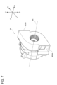
次に、図4を参照しつつ、ヒートシンク7について説明する。ヒートシンク7は、例えば、アルミニウム等の熱伝導性の高い金属材料やタルク等のフィラーを有する樹脂材料等によって形成されている。ヒートシンク7は、光源1で生じた熱を放熱するように構成されている。図4に例示するように、ヒートシンク7は、複数の放熱フィン71を含む。放熱フィン71は、図4における前方上方向に延びる細長い板状部材である。ただし、放熱フィン71は、棒状、ピン状等の他の形状であってもよい。複数の放熱フィン71は、所定の間隔で配置されている。
図2に例示するように、ダクト8は、ファン6からヒートシンク7へ空気流をガイドするように構成されている。つまり、第一ランプユニット10は、ヒートシンク7に向けて、空気を移動させることができる。ダクト8は、屈曲性を有する材料または構造から形成される。このような材料は、例えば、アクリル樹脂、塩化ビニル樹脂等の樹脂材料、ステンレス鋼板等の金属材料、紙材料等である。なお、屈曲性とは、その物品の形に添うように曲がる性質をいう。また、ダクト8の形状は、山折りと谷折りの繰り返し構造である蛇腹形状である。ダクト8は、蛇腹形状に形成されることによっても、屈曲性が付与されている。したがって、ダクト8は、所望の方向に屈曲されうる。
ダクト8は、ファン6に対して、留め具9Aによって固定されている。また、ダクト8は、ヒートシンク7に対して、留め具9Bによって固定されている。本実施形態において、留め具9Aはタイバンドであり、留め具9Bはネジである。なお、タイバンドとは、段階的に環状体の周方向における寸法を調節し、物体を保持することが可能な部材をいう。なお、留め具9Aおよび留め具9Bはこの例に限られず、例えば、留め具9Aおよび留め具9Bは共にタイバンドまたはネジであってもよいし、留め具9Aはネジで留め具9Bはタイバンドであってもよい。また、留め具9Aおよび留め具9Bの少なくとも一方がネジである場合、ダクト8は、スクリュ締結により、ファン6および/またはヒートシンク7に対して、比較的強く固定される。なお、ダクト8は、ファン6およびヒートシンク7に対して、タイバンドまたはネジによって固定されていなくてもよい。ダクト8は、例えば、ファン6およびヒートシンク7に対して、両面テープまたは接着剤によって固定されていてもよい。
上記構成に係る第一ランプユニット10によれば、第一ランプユニット10に備わるダクト8は、ファン6からヒートシンク7へ空気流をガイドする。また、ダクト8は、屈曲性を有する。このため、第一ランプユニット10によれば、ファン6とヒートシンク7の位置関係に依存することなく、ダクト8を比較的自由に配置することができる。したがって、第一ランプユニット10によれば、ヒートシンク7の設計変更に対して適合させやすい第一ランプユニット10を提供することができる。
また、上記構成に係る第一ランプユニット10によれば、ファン6はモータ4の外周側に配置されている。つまり、ファン6はモータ4の回転軸から見てモータ4の外側に配置されているので、軸方向の長さを小さくすることができる。したがって、第一ランプユニット10は、比較的コンパクトであり、車両に搭載させやすい。
また、上記構成に係る第一ランプユニット10によれば、ダクト8は、ヒートシンク7に対して、留め具9Bによって固定されている。つまり、ダクト8は、屈曲性を有しつつ、ヒートシンク7に対して固定されている。したがって、第一ランプユニット10によれば、ダクト8を所望の位置に固定することができる。また、このような第一ランプユニット10は、ダクト8の端部が自由端である場合と比べて、灯具100が搭載された車両が走行している際に生じる振動によるダクト8における送風方向の変位を抑制することができる。つまり、第一ランプユニット10によれば、ダクト8に屈曲性を持たせつつ、灯具100が搭載された車両の走行時に生じる振動によるダクト8における送風方向の変位を抑制することができる。
また、上記構成に係る第一ランプユニット10によれば、留め具9Bはネジであるので、ダクト8とヒートシンク7を容易に、かつ強く固定することができる。
また、上記構成に係る第一ランプユニット10によれば、ダクト8は、蛇腹形状である。したがって、ダクト8は屈曲させやすいので、第一ランプユニット10は、ヒートシンク7の設計変更に対して適合させやすい。
(第二実施形態)
次に、図5および図6を参照しつつ、第二実施形態に係る車両用灯具100Aついて説明する。図5は、本実施形態に係る車両用灯具100Aの概略図である。図6は、図5のY部分の拡大図である。なお、本実施形態において、第一実施形態と同様の構成については同じ符号を付して説明し、説明が重複する部分については適宜説明を省略する。本実施形態に係る車両用灯具100Aは、送風口623に二つのダクト(第一ダクト8Aおよび第二ダクト8B)が取り付けられている点で、第一実施形態に係る車両用灯具100と異なる。
次に、図5および図6を参照しつつ、第二実施形態に係る車両用灯具100Aついて説明する。図5は、本実施形態に係る車両用灯具100Aの概略図である。図6は、図5のY部分の拡大図である。なお、本実施形態において、第一実施形態と同様の構成については同じ符号を付して説明し、説明が重複する部分については適宜説明を省略する。本実施形態に係る車両用灯具100Aは、送風口623に二つのダクト(第一ダクト8Aおよび第二ダクト8B)が取り付けられている点で、第一実施形態に係る車両用灯具100と異なる。
図5に例示するように、灯具100Aは、第一ランプユニット10Aと、第二ランプユニット20と、担体30と、レベリング機構40と、ハウジング50と、を備える。第一ランプユニット10A、第二ランプユニット20、担体30およびレベリング機構40は、ハウジング50内に収容されている。第一ランプユニット10Aは、光源1と、投影レンズ2と、回転ミラー3と、モータ4と、基板5と、ファン6と、ヒートシンク7と、第一ダクト8Aと、第二ダクト8Bと、を備える。第一ダクト8Aおよび第二ダクト8Bは、第一実施形態に係るダクト8と同様に、屈曲性を有する。
図5および図6に例示するように、第一ダクト8A(図5参照)および第二ダクト8B(図5参照)は、送風口623(図6参照)に取り付けられている。つまり、第一ランプユニット10Aに備わるファン6が有する送風口623には、二つに分岐したダクト(第一ダクト8Aおよび第二ダクト8B)が取り付けられている。
図5に例示するように、第一ダクト8Aは、第一ランプユニット10Aに備わるヒートシンク7に取り付けられている。第二ダクト8Bは、第二ランプユニット20に備わるヒートシンク203に取り付けられている。
第一ダクト8Aは、ファン6に対して、留め具9Aによって固定されている。また、第一ダクト8Aは、ヒートシンク7に対して、留め具9Bによって固定されている。なお、本実施形態において、留め具9Aはタイバンドであり、留め具9Bはネジである。
第一ダクト8Aは、ファン6からヒートシンク7へ空気流をガイドするように構成されている。したがって、第一ランプユニット10Aは、第一実施形態に係る第一ランプユニット10と同様に、ヒートシンク7に向けて、空気を移動させることができる。なお、第一ダクト8Aは、ファン6およびヒートシンク7に対して、タイバンドまたはネジによって固定されていなくてもよい。第一ダクト8Aは、例えば、ファン6およびヒートシンク7に対して、両面テープまたは接着剤によって固定されていてもよい。
第二ダクト8Bは、ファン6に対して、留め具90Aによって固定されている。第二ダクト8Bは、ヒートシンク203に対して、留め具90Bによって固定されている。なお、本実施形態において、留め具90Aはタイバンドであり、留め具90Bはネジである。なお、留め具90Aおよび留め具90Bはこの例に限られず、例えば、留め具90Aおよび留め具90Bは共にタイバンドまたはネジであってもよいし、留め具90Aはネジで留め具90Bはタイバンドであってもよい。また、留め具90Aおよび留め具90Bの少なくとも一方がネジである場合、第二ダクト8Bは、スクリュ締結により、ファン6および/またはヒートシンク203に対して、比較的強く固定される。なお、第二ダクト8Bは、ファン6およびヒートシンク203に対して、タイバンドまたはネジによって固定されていなくてもよい。第二ダクト8Bは、例えば、ファン6およびヒートシンク203に対して、両面テープまたは接着剤によって固定されていてもよい。
第二ダクト8Bは、ファン6からヒートシンク203へ空気流をガイドするように構成されている。したがって、第一ランプユニット10Aは、ヒートシンク7のみならず、ヒートシンク203に向けて、空気を移動させることもできる。
上記構成に係る第一ランプユニット10Aによっても、第一実施形態と同様の効果を奏することができる。
また、上記構成に係る第一ランプユニット10Aによれば、第一ダクト8Aおよび第二ダクト8Bにより、第一ランプユニット10Aに備わるヒートシンク7および第二ランプユニット20に備わるヒートシンク203に空気を移動させる。つまり、第一ランプユニット10Aは、複数の冷却対象物(第一ランプユニット10Aの光源1および第二ランプユニット20の光源201A)に向けて、空気を移動させることができる。また、回転ミラー3を回転させるためのモータ4には比較的高い出力が求められるので、モータ4の最大出力は比較的大きい。このため、モータ4であれば、回転ミラー3の回転に対してのみならず、ファン6の回転に対しても比較的大きな出力を出すことができる。つまり、第一ランプユニット10Aによれば、モータ4の既存の出力で(つまり、モータ4の出力を高めたり、他のモータを追加することなく)、複数の冷却対象物を冷却することができる。なお、冷却対象物は、第一ランプユニット10Aの光源1および第二ランプユニット20の光源201Aに限られず、例えば、ランプ内に配置されたミリ波レーダ、カメラ、LiDAR等の各種センサーであってもよい。
また、上記構成に係る第一ランプユニット10Aによれば、送風口623には、二つに分岐した第一ダクト8Aおよび第二ダクト8Bが取り付けられている。したがって、ファン6の送風口623が一つであったとしても、空気を二以上の方向に向けて移動させることができる。
上述したように、屈曲性を有する第一ダクト8Aおよび第二ダクト8Bを採用した場合には、ファン6と電子装置201等との位置関係が変化しても、第一ダクト8Aおよび第二ダクト8Bが屈曲することにより、当該位置関係の変化に追随することができる。しかしながら、ファン6と電子装置201等の接続先との位置関係が変化すると、常に、第一ダクト8Aおよび第二ダクト8Bの特定箇所のみに繰り返し変形が作用し、第一ダクト8Aおよび第二ダクト8Bが破損しやすい。本実施形態では、第一ランプユニット10Aと電子装置201を備えた第二ランプユニット20が共通の担体30に支持されている。また、本実施形態においては、レベリング機構40により、第一ランプユニット10Aの位置が変化した場合でも、第一ランプユニット10Aと電子装置201を備えた第二ランプユニット20との位置関係は変化しない。したがって、上記構成に係る車両用灯具100Aによれば、第一ダクト8Aおよび第二ダクト8Bの破損を抑制することができる。
(第二実施形態の変形例)
次に、図7を参照しつつ、第二実施形態の変形例について説明する。本変形例に係るファン6Aを例示する図である。なお、本変形例において、第一実施形態および第二実施形態と同様の構成については同じ符号を付して説明し、説明が重複する部分については適宜説明を省略する。本変形例に係るファン6Aは、第一送風口623Aおよび第二送風口623Bを有している点で、第二実施形態に係るファン6と異なる。
次に、図7を参照しつつ、第二実施形態の変形例について説明する。本変形例に係るファン6Aを例示する図である。なお、本変形例において、第一実施形態および第二実施形態と同様の構成については同じ符号を付して説明し、説明が重複する部分については適宜説明を省略する。本変形例に係るファン6Aは、第一送風口623Aおよび第二送風口623Bを有している点で、第二実施形態に係るファン6と異なる。
図7に例示するように、ファン6Aは、シロッコファンである。ファン6Aは、第一送風口623Aと、第二送風口623Bと、を備えている。なお、図7に示す例では図示していないが、例えば、第一送風口623Aには第一ダクト8A(図5参照)が、第二送風口623Bには第二ダクト8B(図5参照)が、それぞれ取り付けられる。
第一送風口623Aおよび第二送風口623Bは、回転軸AXの方向から見て、回転軸AXを中心として180度離れた位置に配置されている。したがって、本変形例において、ファン6Aで生じた空気流は、異なる二つの方向に向けてガイドされる。このため、ファン6Aは、複数の冷却対象物(例えば、図5に例示する第一ランプユニット10Aの光源1および第二ランプユニット20の光源201A)に向けて空気を送ることできる。その結果、当該複数の冷却対象物は、ファン6Aから送られてきた空気により、冷却される。
上記構成に係るファン6Aを備える第一ランプユニットによっても、第一実施形態および第二実施形態と同様の効果を奏することができる。
また、上記構成に係るファン6Aを備える第一ランプユニットによれば、ファン6Aには第一送風口623Aおよび第二送風口623Bが設けられているので、複数の方向に空気を送ることができる。
また、上記構成に係るファン6Aを備える第一ランプユニットによれば、互いに最も近接した二つの送風口(第一送風口623Aおよび第二送風口623B)は、ファン6Aの回転軸AXの方向から見て、回転軸AXを中心として180度離れた位置に配置されている。つまり、第一送風口623Aおよび第二送風口623Bは、ファン6Aの回転軸AXの方向から見て、回転軸AXを中心として90度以上離れた位置に配置されている。したがって、ファン6Aを備える第一ランプユニットは、空気を効率的に二つの方向に向けて移動させることができる。
以上、本開示の実施形態について説明をしたが、本開示の技術的範囲が本実施形態の説明によって限定的に解釈されるべきではないのは言うまでもない。本実施形態は単なる一例であって、請求の範囲に記載された開示の範囲内において、様々な実施形態の変更が可能であることが当業者によって理解されるところである。本開示の技術的範囲は請求の範囲に記載された開示の範囲およびその均等の範囲に基づいて定められるべきである。
上記の実施形態においては、ファン6,6Aとしてシロッコファンを例示したが、ファン6,6Aは、例えば、軸流ファン(プロペラファン)であってもよい。
上記の第一実施形態において、ダクト8は蛇腹形状であるが、ダクト8は屈曲性を有していればよく、ダクト8の形状は蛇腹形状に限られない。また、上記の第二実施形態および第二実施形態の変形例において、第一ダクト8Aおよび第二ダクト8Bは蛇腹形状であるが、第一ダクト8Aおよび第二ダクト8Bは屈曲性を有していればよく、第一ダクト8Aおよび第二ダクト8Bの形状は蛇腹形状に限られない。
上記の第二実施形態において、第一ランプユニット10Aに備わるファン6は、一つの送風口623を有しており、送風口623には、二つに分岐したダクト(第一ダクト8Aおよび第二ダクト8B)が取り付けられているが、本開示はこれに限られない。例えば、ファン6は、送風口623が設けられている場所において、送風口623の代わりに、二つの送風口を有しており、各送風口に第一ダクト8Aまたは第二ダクト8Bが取り付けられていてもよい。この場合、各送風口は、例えば、上下方向に並ぶように設けられており、上側の送風口には第一ダクト8Aが、下側の送風口には第二ダクト8Bが取り付けられる。また、ファン6が有する送風口の数は、一つまたは二つに限られない。ファン6は、三つ以上の送風口を有していてもよい。なお、各送風口には、一つのダクトが取り付けられてもよいし、二つ以上に分岐したダクトが取り付けられてもよい。
上記の第二実施形態において、第一ランプユニット10Aに備わるファン6が有する送風口623には、二つに分岐したダクト(第一ダクト8Aおよび第二ダクト8B)が取り付けられているが、三つ以上に分岐したダクトが取り付けられていてもよい。
上記の第二実施形態の変形例において、ファン6Aに備わる第一送風口623Aおよび第二送風口623Bのそれぞれには、一つのダクトが取り付けられているが、二つ以上に分岐したダクトが取り付けられていてもよい。
第二実施形態の変形例において、ファン6Aは、第一送風口623Aと、第二送風口623Bと、を備えているが、三つ以上の送風口を備えていてもよい。
上記の第二実施形態の変形例において、第一送風口623Aおよび第二送風口623Bは、回転軸AXの方向から見て、回転軸AXを中心として180度離れた位置に配置されているが、90度以上離れた位置に配置されていればよく、180度に限られない。
本出願は、2022年2月14日出願の日本国特許出願(特願2022-020660号)に基づくものであり、その内容はここに参照として取り込まれる。
Claims (10)
- 光を出射する光源と、
前記光源から出射された光を反射させる少なくとも一つの光反射ブレードを含む回転ミラーと、
前記回転ミラーを回転させるためのモータと、
前記モータが駆動することで空気流を生じさせるファンと、
前記光源で生じた熱を放熱するヒートシンクと、
前記ファンから前記ヒートシンクへ前記空気流をガイドするように構成された、屈曲性を有するダクトと、を備える、ランプユニット。 - 前記ファンは、前記モータの外周側に配置されている、請求項1に記載のランプユニット。
- 前記ダクトは、前記ヒートシンクに対して、留め具によって固定されている、請求項1または請求項2に記載のランプユニット。
- 前記留め具は、ネジまたはタイバンドである、請求項3に記載のランプユニット。
- 前記ダクトは、蛇腹形状である、請求項1から請求項4のいずれか一項に記載のランプユニット。
- 前記ダクトは、少なくとも前記ヒートシンクを含む複数の冷却対象物に前記空気流を移動させる、請求項1から請求項5のいずれか一項に記載のランプユニット。
- 前記ファンは、少なくとも一つの送風口を備える、請求項1から請求項6のいずれか一項に記載のランプユニット。
- 前記ファンは、二つ以上の送風口を備えており、
互いに最も近接した二つの前記送風口は、前記ファンの回転軸の方向から見て、前記回転軸を中心として90度以上離れた位置に配置されている、請求項1から請求項7のいずれか一項に記載のランプユニット。 - 前記送風口には、二以上に分岐した前記ダクトが取り付けられている、請求項7または請求項8に記載のランプユニット。
- 請求項1から請求項9のいずれか一項に記載のランプユニットと、
前記ランプユニットと、前記ランプユニットとは異なる熱を生じさせる電子装置と、を支持する共通の担体と、を備え、
前記ファンは、前記ファンの回転により、前記電子装置にも空気を送る、車両用灯具。
Priority Applications (1)
| Application Number | Priority Date | Filing Date | Title |
|---|---|---|---|
| JP2023580128A JPWO2023153145A1 (ja) | 2022-02-14 | 2023-01-16 |
Applications Claiming Priority (2)
| Application Number | Priority Date | Filing Date | Title |
|---|---|---|---|
| JP2022-020660 | 2022-02-14 | ||
| JP2022020660 | 2022-02-14 |
Publications (1)
| Publication Number | Publication Date |
|---|---|
| WO2023153145A1 true WO2023153145A1 (ja) | 2023-08-17 |
Family
ID=87564295
Family Applications (1)
| Application Number | Title | Priority Date | Filing Date |
|---|---|---|---|
| PCT/JP2023/001011 Ceased WO2023153145A1 (ja) | 2022-02-14 | 2023-01-16 | ランプユニットおよび車両用灯具 |
Country Status (2)
| Country | Link |
|---|---|
| JP (1) | JPWO2023153145A1 (ja) |
| WO (1) | WO2023153145A1 (ja) |
Citations (6)
| Publication number | Priority date | Publication date | Assignee | Title |
|---|---|---|---|---|
| JP2002160579A (ja) * | 2000-11-28 | 2002-06-04 | Hitachi Ltd | 前照灯及び送受信装置 |
| JP2009158265A (ja) * | 2007-12-26 | 2009-07-16 | Stanley Electric Co Ltd | 換気穴付き車両用灯具 |
| KR20150047826A (ko) * | 2013-10-25 | 2015-05-06 | 엘지전자 주식회사 | 차량용 램프 장치 |
| JP2018063891A (ja) * | 2016-10-13 | 2018-04-19 | 株式会社小糸製作所 | 光源ユニットおよび灯具 |
| JP2019003908A (ja) * | 2017-06-20 | 2019-01-10 | 株式会社小糸製作所 | ランプユニット |
| JP2020123486A (ja) * | 2019-01-30 | 2020-08-13 | 株式会社小糸製作所 | 車両用灯具 |
-
2023
- 2023-01-16 WO PCT/JP2023/001011 patent/WO2023153145A1/ja not_active Ceased
- 2023-01-16 JP JP2023580128A patent/JPWO2023153145A1/ja active Pending
Patent Citations (6)
| Publication number | Priority date | Publication date | Assignee | Title |
|---|---|---|---|---|
| JP2002160579A (ja) * | 2000-11-28 | 2002-06-04 | Hitachi Ltd | 前照灯及び送受信装置 |
| JP2009158265A (ja) * | 2007-12-26 | 2009-07-16 | Stanley Electric Co Ltd | 換気穴付き車両用灯具 |
| KR20150047826A (ko) * | 2013-10-25 | 2015-05-06 | 엘지전자 주식회사 | 차량용 램프 장치 |
| JP2018063891A (ja) * | 2016-10-13 | 2018-04-19 | 株式会社小糸製作所 | 光源ユニットおよび灯具 |
| JP2019003908A (ja) * | 2017-06-20 | 2019-01-10 | 株式会社小糸製作所 | ランプユニット |
| JP2020123486A (ja) * | 2019-01-30 | 2020-08-13 | 株式会社小糸製作所 | 車両用灯具 |
Also Published As
| Publication number | Publication date |
|---|---|
| JPWO2023153145A1 (ja) | 2023-08-17 |
Similar Documents
| Publication | Publication Date | Title |
|---|---|---|
| JP6940310B2 (ja) | ランプユニット | |
| US7481561B2 (en) | Vehicle lighting device | |
| JP5248183B2 (ja) | 車両用灯具 | |
| US6790003B1 (en) | Cooling fan with flashing light effect | |
| BR0307669B1 (pt) | montagem de ventilador para esfriamento de motor com ventiladores sobrepostos. | |
| US20110242834A1 (en) | Headlamp assembly for motor vehicle | |
| US9395073B2 (en) | Cooling unit and illuminating apparatus | |
| US20120287651A1 (en) | Illumination apparatus and fan unit for illumination apparatus | |
| CN116157626B (zh) | 车辆用灯具 | |
| JP2018063891A (ja) | 光源ユニットおよび灯具 | |
| EP1772666A1 (en) | Vehicle lamp | |
| JP6464941B2 (ja) | 車両用灯具 | |
| CN110832245A (zh) | 灯单元 | |
| US10429059B1 (en) | Cooling fan | |
| WO2023153145A1 (ja) | ランプユニットおよび車両用灯具 | |
| JP2016173942A (ja) | 車両用前照灯 | |
| JP2011258411A (ja) | 車両用灯具 | |
| JP2006117164A (ja) | 車両用前照灯 | |
| JP2022146353A (ja) | モータユニット、ファン付きモータユニットおよびランプユニット | |
| WO2020027128A1 (ja) | 車両用灯具 | |
| US20240410544A1 (en) | Lamp fitting, and vehicular headlamp | |
| JP2019175680A (ja) | 車両用灯具 | |
| CN101156103B (zh) | 光扫描用促动器 | |
| CN211345250U (zh) | 灯具单元 | |
| CN222437740U (zh) | 一种星云透镜模组及带有其的星空投影设备 |
Legal Events
| Date | Code | Title | Description |
|---|---|---|---|
| 121 | Ep: the epo has been informed by wipo that ep was designated in this application |
Ref document number: 23752614 Country of ref document: EP Kind code of ref document: A1 |
|
| ENP | Entry into the national phase |
Ref document number: 2023580128 Country of ref document: JP Kind code of ref document: A |
|
| NENP | Non-entry into the national phase |
Ref country code: DE |
|
| 122 | Ep: pct application non-entry in european phase |
Ref document number: 23752614 Country of ref document: EP Kind code of ref document: A1 |