WO2023152586A1 - 半導体装置、及び半導体装置の作製方法 - Google Patents
半導体装置、及び半導体装置の作製方法 Download PDFInfo
- Publication number
- WO2023152586A1 WO2023152586A1 PCT/IB2023/050698 IB2023050698W WO2023152586A1 WO 2023152586 A1 WO2023152586 A1 WO 2023152586A1 IB 2023050698 W IB2023050698 W IB 2023050698W WO 2023152586 A1 WO2023152586 A1 WO 2023152586A1
- Authority
- WO
- WIPO (PCT)
- Prior art keywords
- insulator
- conductor
- metal oxide
- transistor
- region
- Prior art date
- Legal status (The legal status is an assumption and is not a legal conclusion. Google has not performed a legal analysis and makes no representation as to the accuracy of the status listed.)
- Ceased
Links
Images








Classifications
-
- G—PHYSICS
- G11—INFORMATION STORAGE
- G11C—STATIC STORES
- G11C11/00—Digital stores characterised by the use of particular electric or magnetic storage elements; Storage elements therefor
- G11C11/21—Digital stores characterised by the use of particular electric or magnetic storage elements; Storage elements therefor using electric elements
- G11C11/34—Digital stores characterised by the use of particular electric or magnetic storage elements; Storage elements therefor using electric elements using semiconductor devices
- G11C11/40—Digital stores characterised by the use of particular electric or magnetic storage elements; Storage elements therefor using electric elements using semiconductor devices using transistors
- G11C11/401—Digital stores characterised by the use of particular electric or magnetic storage elements; Storage elements therefor using electric elements using semiconductor devices using transistors forming cells needing refreshing or charge regeneration, i.e. dynamic cells
- G11C11/403—Digital stores characterised by the use of particular electric or magnetic storage elements; Storage elements therefor using electric elements using semiconductor devices using transistors forming cells needing refreshing or charge regeneration, i.e. dynamic cells with charge regeneration common to a multiplicity of memory cells, i.e. external refresh
- G11C11/405—Digital stores characterised by the use of particular electric or magnetic storage elements; Storage elements therefor using electric elements using semiconductor devices using transistors forming cells needing refreshing or charge regeneration, i.e. dynamic cells with charge regeneration common to a multiplicity of memory cells, i.e. external refresh with three charge-transfer gates, e.g. MOS transistors, per cell
-
- H—ELECTRICITY
- H10—SEMICONDUCTOR DEVICES; ELECTRIC SOLID-STATE DEVICES NOT OTHERWISE PROVIDED FOR
- H10B—ELECTRONIC MEMORY DEVICES
- H10B12/00—Dynamic random access memory [DRAM] devices
-
- H—ELECTRICITY
- H10—SEMICONDUCTOR DEVICES; ELECTRIC SOLID-STATE DEVICES NOT OTHERWISE PROVIDED FOR
- H10B—ELECTRONIC MEMORY DEVICES
- H10B12/00—Dynamic random access memory [DRAM] devices
- H10B12/30—DRAM devices comprising one-transistor - one-capacitor [1T-1C] memory cells
- H10B12/31—DRAM devices comprising one-transistor - one-capacitor [1T-1C] memory cells having a storage electrode stacked over the transistor
- H10B12/312—DRAM devices comprising one-transistor - one-capacitor [1T-1C] memory cells having a storage electrode stacked over the transistor with a bit line higher than the capacitor
-
- H—ELECTRICITY
- H10—SEMICONDUCTOR DEVICES; ELECTRIC SOLID-STATE DEVICES NOT OTHERWISE PROVIDED FOR
- H10B—ELECTRONIC MEMORY DEVICES
- H10B41/00—Electrically erasable-and-programmable ROM [EEPROM] devices comprising floating gates
- H10B41/70—Electrically erasable-and-programmable ROM [EEPROM] devices comprising floating gates the floating gate being an electrode shared by two or more components
-
- H—ELECTRICITY
- H10—SEMICONDUCTOR DEVICES; ELECTRIC SOLID-STATE DEVICES NOT OTHERWISE PROVIDED FOR
- H10B—ELECTRONIC MEMORY DEVICES
- H10B99/00—Subject matter not provided for in other groups of this subclass
-
- H—ELECTRICITY
- H10—SEMICONDUCTOR DEVICES; ELECTRIC SOLID-STATE DEVICES NOT OTHERWISE PROVIDED FOR
- H10D—INORGANIC ELECTRIC SEMICONDUCTOR DEVICES
- H10D30/00—Field-effect transistors [FET]
- H10D30/60—Insulated-gate field-effect transistors [IGFET]
- H10D30/67—Thin-film transistors [TFT]
- H10D30/6729—Thin-film transistors [TFT] characterised by the electrodes
- H10D30/673—Thin-film transistors [TFT] characterised by the electrodes characterised by the shapes, relative sizes or dispositions of the gate electrodes
-
- H—ELECTRICITY
- H10—SEMICONDUCTOR DEVICES; ELECTRIC SOLID-STATE DEVICES NOT OTHERWISE PROVIDED FOR
- H10D—INORGANIC ELECTRIC SEMICONDUCTOR DEVICES
- H10D30/00—Field-effect transistors [FET]
- H10D30/60—Insulated-gate field-effect transistors [IGFET]
- H10D30/67—Thin-film transistors [TFT]
- H10D30/6729—Thin-film transistors [TFT] characterised by the electrodes
- H10D30/673—Thin-film transistors [TFT] characterised by the electrodes characterised by the shapes, relative sizes or dispositions of the gate electrodes
- H10D30/6733—Multi-gate TFTs
- H10D30/6734—Multi-gate TFTs having gate electrodes arranged on both top and bottom sides of the channel, e.g. dual-gate TFTs
-
- H—ELECTRICITY
- H10—SEMICONDUCTOR DEVICES; ELECTRIC SOLID-STATE DEVICES NOT OTHERWISE PROVIDED FOR
- H10D—INORGANIC ELECTRIC SEMICONDUCTOR DEVICES
- H10D30/00—Field-effect transistors [FET]
- H10D30/60—Insulated-gate field-effect transistors [IGFET]
- H10D30/67—Thin-film transistors [TFT]
- H10D30/674—Thin-film transistors [TFT] characterised by the active materials
- H10D30/6755—Oxide semiconductors, e.g. zinc oxide, copper aluminium oxide or cadmium stannate
-
- H—ELECTRICITY
- H10—SEMICONDUCTOR DEVICES; ELECTRIC SOLID-STATE DEVICES NOT OTHERWISE PROVIDED FOR
- H10D—INORGANIC ELECTRIC SEMICONDUCTOR DEVICES
- H10D30/00—Field-effect transistors [FET]
- H10D30/60—Insulated-gate field-effect transistors [IGFET]
- H10D30/67—Thin-film transistors [TFT]
- H10D30/6757—Thin-film transistors [TFT] characterised by the structure of the channel, e.g. transverse or longitudinal shape or doping profile
-
- H—ELECTRICITY
- H10—SEMICONDUCTOR DEVICES; ELECTRIC SOLID-STATE DEVICES NOT OTHERWISE PROVIDED FOR
- H10D—INORGANIC ELECTRIC SEMICONDUCTOR DEVICES
- H10D99/00—Subject matter not provided for in other groups of this subclass
-
- H—ELECTRICITY
- H10—SEMICONDUCTOR DEVICES; ELECTRIC SOLID-STATE DEVICES NOT OTHERWISE PROVIDED FOR
- H10W—GENERIC PACKAGES, INTERCONNECTIONS, CONNECTORS OR OTHER CONSTRUCTIONAL DETAILS OF DEVICES COVERED BY CLASS H10
- H10W20/00—Interconnections in chips, wafers or substrates
- H10W20/40—Interconnections external to wafers or substrates, e.g. back-end-of-line [BEOL] metallisations or vias connecting to gate electrodes
- H10W20/41—Interconnections external to wafers or substrates, e.g. back-end-of-line [BEOL] metallisations or vias connecting to gate electrodes characterised by their conductive parts
- H10W20/435—Cross-sectional shapes or dispositions of interconnections
Definitions
- One embodiment of the present invention relates to semiconductor devices, memory devices, and electronic devices. Another embodiment of the present invention relates to a method for manufacturing a semiconductor device.
- one embodiment of the present invention is not limited to the above technical field.
- Technical fields of one embodiment of the present invention include semiconductor devices, display devices, light-emitting devices, power storage devices, storage devices, electronic devices, lighting devices, input devices (e.g., touch sensors), input/output devices (e.g., touch panels), The method of driving them or the method of manufacturing them can be given as an example.
- a semiconductor device in this specification and the like refers to all devices that can function by utilizing semiconductor characteristics.
- a semiconductor element such as a transistor, a semiconductor circuit, an arithmetic device, and a memory device are examples of semiconductor devices.
- a display device (a liquid crystal display device, a light-emitting display device, or the like), a projection device, a lighting device, an electro-optical device, a power storage device, a memory device, a semiconductor circuit, an imaging device, an electronic device, or the like can be said to include a semiconductor device in some cases.
- LSIs Large Scale Integration
- CPUs Central Processing Units
- memories storage devices
- DRAM Dynamic Random Access Memory
- SRAM Static Random Access Memory
- flash memory flash memory
- Patent Document 1 and Non-Patent Document 1 disclose a memory cell formed by stacking transistors.
- An object of one embodiment of the present invention is to provide a semiconductor device that can be miniaturized or highly integrated.
- An object of one embodiment of the present invention is to provide a semiconductor device that operates at high speed.
- An object of one embodiment of the present invention is to provide a semiconductor device with favorable electrical characteristics.
- An object of one embodiment of the present invention is to provide a semiconductor device in which variations in electrical characteristics of transistors are small.
- An object of one embodiment of the present invention is to provide a highly reliable semiconductor device.
- An object of one embodiment of the present invention is to provide a semiconductor device with high on-state current.
- An object of one embodiment of the present invention is to provide a semiconductor device with low power consumption.
- An object of one embodiment of the present invention is to provide a novel semiconductor device.
- An object of one embodiment of the present invention is to provide a method for manufacturing a semiconductor device in which the number of steps is small.
- An object of one embodiment of the present invention is to provide a storage device with a large storage capacity.
- An object of one embodiment of the present invention is to provide a memory device that occupies a small area.
- An object of one embodiment of the present invention is to provide a highly reliable storage device.
- An object of one embodiment of the present invention is to provide a memory device with low power consumption.
- An object of one embodiment of the present invention is to provide a novel storage device.
- One embodiment of the present invention includes a first transistor, a second transistor, a third transistor, a capacitor, a first conductor, a first insulator, a second insulator, and a third transistor.
- the first transistor includes a first metal oxide, a second conductor, a third conductor, a fourth conductor, and a fourth insulator and wherein the second conductor and the third conductor cover part of the top surface and the side surface of the first metal oxide, respectively, and the fourth insulator covers the first metal oxide.
- a fourth conductor overlying a fourth insulator; a second transistor overlying a second metal oxide; a fifth conductor; a sixth conductor; A seventh conductor and a fifth insulator, the fifth conductor covering a portion of the top surface and side surfaces of the second metal oxide, and the sixth conductor covering the second metal oxide.
- the transistor has a second metal oxide, a sixth conductor, an eighth conductor, a ninth conductor, and a sixth insulator, the eighth conductor comprising: A sixth insulator is provided over the second metal oxide, and a ninth conductor is provided over the sixth insulator, covering part of the top surface and side surfaces of the second metal oxide.
- a second conductor is provided over the insulator, the fourth conductor, the seventh conductor, and the ninth conductor;
- a capacitor is provided over the second insulator;
- a third insulator is provided so as to cover part of the upper surface and side surfaces of the second insulator, and the side surface of the second conductor, the side surface of the first insulator, and the side surface of the third insulator.
- a first conductor is provided so as to have a contact region, and the third conductor is a semiconductor device electrically connected to the seventh conductor.
- At least part of the width of the region in contact with the side surface of the first insulator and the width of the region in contact with the side surface of the third insulator in a cross-sectional view of the first conductor It may be larger than the width of the region in contact with the side surface of the second conductor.
- the capacitance is formed by the tenth conductor over the second insulator, the seventh insulator over the tenth conductor, and the eleventh conductor over the seventh insulator.
- the tenth conductor may be electrically connected to the third conductor and the seventh conductor.
- the semiconductor device has an eighth insulator covering part of the top surface and side surfaces of the seventh insulator, and has a region in contact with the side surface of the eighth insulator.
- One electrical conductor may be provided.
- the tenth conductor may have a region in contact with the side surface of the third insulator.
- the first metal oxide and the second metal oxide may contain indium, zinc, and one or more selected from gallium, aluminum, and tin.
- a first metal oxide and a second metal oxide are formed, and a first conductive layer covering a top surface and side surfaces of the first metal oxide and a second metal oxide are formed.
- a fifth insulator is formed over the eighth to eighth conductors, a fourth opening is formed in the fifth insulator, and a sixth insulator is formed over the fifth insulator to cover the fourth opening.
- a ninth conductor electrically connected to the second conductor and the seventh conductor over the fifth insulator; forming a ninth conductor over the ninth conductor; and forming a seventh insulator over the fourth opening, forming a fifth opening having a region overlapping with the fourth opening in the seventh insulator, and covering the fifth opening, forming an eighth insulator over the seventh insulator; forming a sixth opening in the eighth insulator to have a region overlapping with the ninth conductor; , a tenth conductor, and a seventh insulator on the first insulator, the sixth insulator, and the eighth insulator to have regions overlapping the fourth and fifth openings.
- An opening is formed to expose a side surface of a first conductor, and an eleventh conductor is formed inside the seventh opening so as to have a region in contact with the side surface of the first conductor. It is a manufacturing method.
- the side surface of the first conductor exposed by forming the seventh opening may be positioned inside the seventh opening from the side surface of the first insulator in a cross-sectional view.
- a semiconductor device that can be miniaturized or highly integrated can be provided.
- a semiconductor device with high operating speed can be provided.
- a semiconductor device with favorable electrical characteristics can be provided.
- a semiconductor device with little variation in electrical characteristics of transistors can be provided.
- a highly reliable semiconductor device can be provided.
- a semiconductor device with high on-state current can be provided.
- a semiconductor device with low power consumption can be provided.
- One embodiment of the present invention can provide a novel semiconductor device.
- a method for manufacturing a semiconductor device in which the number of steps is small can be provided.
- a storage device with a large storage capacity can be provided.
- a memory device that occupies a small area can be provided.
- a highly reliable storage device can be provided.
- a memory device with low power consumption can be provided.
- An aspect of the present invention can provide a novel storage device.
- FIG. 1 is a cross-sectional view showing a configuration example of a semiconductor device.
- FIG. 2A is a cross-sectional view showing a configuration example of a semiconductor device.
- FIG. 2B is a cross-sectional view showing a configuration example of a transistor.
- FIG. 3 is a cross-sectional view showing a configuration example of a semiconductor device.
- FIG. 4 is a cross-sectional view showing a configuration example of a semiconductor device.
- FIG. 5 is a cross-sectional view showing a configuration example of a semiconductor device.
- 6A and 6B are cross-sectional views showing configuration examples of semiconductor devices.
- FIG. 7 is a cross-sectional view showing a configuration example of a semiconductor device.
- FIG. 1 is a cross-sectional view showing a configuration example of a semiconductor device.
- FIG. 2A is a cross-sectional view showing a configuration example of a semiconductor device.
- FIG. 2B is a cross-sectional view showing a configuration
- FIG. 8 is a cross-sectional view showing a configuration example of a semiconductor device.
- 9A and 9B are cross-sectional views showing configuration examples of semiconductor devices.
- FIG. 10 is a cross-sectional view showing a configuration example of a semiconductor device.
- FIG. 11 is a cross-sectional view showing a configuration example of a semiconductor device.
- FIG. 12 is a cross-sectional view showing a configuration example of a semiconductor device.
- FIG. 13 is a cross-sectional view showing a configuration example of a semiconductor device.
- FIG. 14 is a cross-sectional view showing a configuration example of a semiconductor device.
- FIG. 15 is a cross-sectional view showing a configuration example of a semiconductor device.
- FIG. 16 is a cross-sectional view showing a configuration example of a semiconductor device.
- 17A and 17B are plan views showing configuration examples of the semiconductor device.
- 18A and 18B are plan views showing configuration examples of semiconductor devices.
- 19A and 19B are plan views showing configuration examples of semiconductor devices.
- 20A and 20B are plan views showing configuration examples of semiconductor devices.
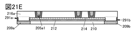
- 21A to 21G are cross-sectional views illustrating an example of a method for manufacturing a semiconductor device.
- 22A to 22C are cross-sectional views illustrating an example of a method for manufacturing a semiconductor device.
- 23A and 23B are cross-sectional views illustrating an example of a method for manufacturing a semiconductor device.
- 24A and 24B are cross-sectional views illustrating an example of a method for manufacturing a semiconductor device.
- 25A and 25B are cross-sectional views illustrating an example of a method for manufacturing a semiconductor device.
- 26A and 26B are cross-sectional views illustrating an example of a method for manufacturing a semiconductor device.
- 27A and 27B are cross-sectional views illustrating an example of a method for manufacturing a semiconductor device.
- 28A and 28B are cross-sectional views illustrating an example of a method for manufacturing a semiconductor device.
- 29A and 29B are cross-sectional views illustrating an example of a method for manufacturing a semiconductor device.
- 30A to 30C are cross-sectional views illustrating an example of a method for manufacturing a semiconductor device.
- 31A to 31C are cross-sectional views illustrating an example of a method for manufacturing a semiconductor device.
- 32A to 32G are cross-sectional views illustrating an example of a method for manufacturing a semiconductor device.
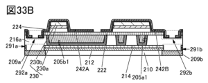
- 33A to 33C are cross-sectional views illustrating an example of a method for manufacturing a semiconductor device.
- 34A and 34B are cross-sectional views illustrating an example of a method for manufacturing a semiconductor device.
- 35A and 35B are cross-sectional views illustrating an example of a method for manufacturing a semiconductor device.
- 36A and 36B are cross-sectional views illustrating an example of a method for manufacturing a semiconductor device.
- 37A and 37B are cross-sectional views illustrating an example of a method for manufacturing a semiconductor device.
- 38A and 38B are cross-sectional views illustrating an example of a method for manufacturing a semiconductor device.
- 39A and 39B are cross-sectional views illustrating an example of a method for manufacturing a semiconductor device.
- FIG. 40A to 40C are cross-sectional views illustrating an example of a method for manufacturing a semiconductor device.
- FIG. 41 is a cross-sectional view showing an example of a method for manufacturing a semiconductor device.
- 42A to 42C are cross-sectional views illustrating an example of a method for manufacturing a semiconductor device.
- 43A to 43D are cross-sectional views illustrating an example of a method for manufacturing a semiconductor device.
- 44A and 44B are cross-sectional views illustrating an example of a method for manufacturing a semiconductor device.
- 45A and 45B are cross-sectional views illustrating an example of a method for manufacturing a semiconductor device.
- 46A and 46B are cross-sectional views illustrating an example of a method for manufacturing a semiconductor device.
- FIG. 47A and 47B are cross-sectional views illustrating an example of a method for manufacturing a semiconductor device.
- FIG. 48 is a cross-sectional view showing an example of a method for manufacturing a semiconductor device.
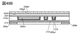
- 49A to 49D are cross-sectional views illustrating an example of a method for manufacturing a semiconductor device.
- 50A and 50B are cross-sectional views illustrating an example of a method for manufacturing a semiconductor device.
- 51A and 51B are cross-sectional views illustrating an example of a method for manufacturing a semiconductor device.
- FIG. 52 is a cross-sectional view showing an example of a method for manufacturing a semiconductor device.
- FIG. 53 is a cross-sectional view showing an example of a method for manufacturing a semiconductor device.
- FIG. 54 is a cross-sectional view showing an example of a method for manufacturing a semiconductor device.
- 55A and 55B are diagrams showing examples of storage devices.
- 56A and 56B are circuit diagrams showing examples of memory layers.
- FIG. 57 is a timing chart for explaining an operation example of the memory cell.
- 58A and 58B are circuit diagrams for explaining an operation example of the memory cell.
- 59A and 59B are circuit diagrams for explaining an operation example of the memory cell.
- FIG. 60 is a circuit diagram showing a configuration example of a semiconductor device.
- 61A and 61B are diagrams showing an example of a semiconductor device.
- 62A and 62B are diagrams showing an example of an electronic component.
- 63A to 63J are diagrams showing examples of electronic devices.
- 64A to 64E are diagrams showing examples of electronic devices.
- 65A to 65C are diagrams illustrating examples of electronic devices.
- FIG. 66 is a diagram showing an example of space equipment
- the same reference numerals may be given to the same elements, elements having similar functions, elements made of the same material, elements formed at the same time, etc., and repeated description thereof will be omitted. may be omitted.
- two identically labeled elements may be separated from each other. For example, even if two conductors are given the same reference numerals, these two conductors may be provided separately.
- the same hatching pattern may be applied to the same elements, elements having similar functions, elements made of the same material, or elements formed at the same time, and reference numerals may be omitted as appropriate. For example, some symbols may be omitted so that two or more identical symbols are not described in one drawing.
- the ordinal numbers “first” and “second” are used for convenience, and limit the number of constituent elements or the order of constituent elements (for example, the order of steps or the order of stacking). not something to do. Also, the ordinal number given to an element in one place in this specification may not match the ordinal number given to that element elsewhere in the specification or in the claims.
- film and “layer” can be interchanged depending on the case or situation.
- conductive layer can be changed to the term “conductive film.”
- insulating film can be changed to the term “insulating layer”.
- One embodiment of the present invention relates to a semiconductor device in which a memory layer is provided over a substrate.
- the memory layer has a first transistor, a second transistor, a third transistor, and a capacitor, which can constitute a memory cell. Since a semiconductor device of one embodiment of the present invention includes memory cells, it has a function of storing data. Therefore, a semiconductor device of one embodiment of the present invention can be called a memory device.
- the first transistor includes a first metal oxide, first and second conductors covering part of the top surface and side surfaces of the first metal oxide, and the first conductor and the second conductor. a first insulator provided between and a third conductor on the first insulator.
- the second transistor includes a second metal oxide, a fourth conductor covering part of the top surface and side surfaces of the second metal oxide, and a fourth conductor covering part of the top surface of the second metal oxide. 5 conductors, a second insulator provided between the fourth and fifth conductors, and a sixth conductor on the second insulator.
- the third transistor includes a second metal oxide, a fifth conductor, a seventh conductor covering part of the top surface and side surfaces of the second metal oxide, the fifth conductor, and the third conductor. A third insulator provided between seven conductors and an eighth conductor on the third insulator. That is, the second transistor and the third transistor share the second metal oxide and the fifth conductor.
- the first metal oxide has a region that functions as a channel formation region of the first transistor.
- the first conductor has a region that functions as one of the source or drain electrodes of the first transistor.
- the second conductor has a region that functions as the other of the source and drain electrodes of the first transistor.
- the third conductor has a region with a region that functions as the gate electrode of the first transistor.
- the first insulator has a region that functions as a gate insulator for the first transistor.
- the second metal oxide has a region functioning as a channel formation region of the second transistor and a region functioning as a channel formation region of the third transistor.
- a fourth conductor has a region that functions as one of the source or drain electrodes of the second transistor.
- the fifth conductor has regions that function as the other of the source or drain electrodes of the second transistor and one of the source or drain electrodes of the third transistor.
- the sixth conductor has a region that functions as the gate electrode of the second transistor.
- the seventh conductor has a region that functions as the other of the source and drain electrodes of the third transistor.
- the eighth conductor has a region that functions as the gate electrode of the third transistor.
- the second insulator has a region that functions as a gate insulator for the second transistor.
- the third insulator has a region that functions as a gate insulator for the third transistor.
- the second transistor and the third transistor are adjacent to each other and share the second metal oxide and the fifth conductor, respectively, an area smaller than the area of two transistors, for example, 1.1.
- Two transistors can be formed in an area equivalent to five. As a result, the transistors can be arranged with high density, and high integration of the semiconductor device can be realized.
- a semiconductor device of one embodiment of the present invention includes a transistor (OS transistor) including a metal oxide in a channel formation region. Since an OS transistor has a low off-state current, memory content can be retained for a long time by using the OS transistor for a semiconductor device that can be used as a memory device. In other words, since the refresh operation is not required or the frequency of the refresh operation is extremely low, the power consumption of the semiconductor device can be sufficiently reduced. In addition, since the OS transistor has high frequency characteristics, the semiconductor device can read and write data at high speed.
- OS transistor since an OS transistor has a low off-state current, memory content can be retained for a long time by using the OS transistor for a semiconductor device that can be used as a memory device. In other words, since the refresh operation is not required or the frequency of the refresh operation is extremely low, the power consumption of the semiconductor device can be sufficiently reduced. In addition, since the OS transistor has high frequency characteristics, the semiconductor device can read and write data at high speed.
- a plurality of memory layers having the above structure are stacked.
- a plurality of memory layers having the above structure are provided, for example, in a direction perpendicular to the substrate surface.
- bit lines can be provided, for example, in a direction perpendicular to the substrate surface.
- a bit line can be formed by providing an opening through the storage layer and forming a conductor inside the opening.
- a semiconductor device of one embodiment of the present invention has a first bit line and a second bit line, and the first bit line is arranged so as to have a region in contact with the top surface and side surface of the first conductor.
- a conductor is provided having a region that functions as a conductor.
- a conductor having a region that functions as a second bit line so as to have a region in contact with the top and side surfaces of the seventh conductor.
- the semiconductor device of one embodiment of the present invention can be a semiconductor device with high integration of memory cells.
- bit line can be called a write bit line
- the second bit line can be called a read bit line
- FIG. 1 is a cross-sectional view illustrating a structural example of a semiconductor device of one embodiment of the present invention.
- a semiconductor device shown in FIG. 212 , an n-layer (n is an integer of 2 or more) memory layer 11 on the insulator 214 , and the n-layer memory layer 11 are provided so as to be electrically connected to the conductor 209 . It has connected conductors 240a and 240b, an insulator 181 over the memory layer 11_n, an insulator 183 over the insulators 181 and 240, and an insulator 185 over the insulator 183. .
- the components included in the semiconductor device of this embodiment may each have a single-layer structure or a laminated structure.
- the conductor 209 may be used when describing items common to the conductor 209a and the conductor 209b.
- a memory cell array having a plurality of memory cells is provided in each of the memory layers 11_1 to 11_n.
- a memory cell includes a transistor 201 , a transistor 202 , a transistor 203 , and a capacitor 101 .
- a circuit configuration of the memory cell and a driving method will be described in Embodiment Mode 2.
- Each of the conductors 240a and 240b has a region functioning as a bit line.
- data is written to the memory cell through the conductor 240a.
- data held in the memory cell is read through the conductor 240b.
- the conductor 240a can be said to have a region functioning as a write bit line
- the conductor 240b can be said to have a region functioning as a read bit line.
- the direction parallel to the channel length direction of the illustrated transistor is defined as the X direction
- the direction parallel to the channel width direction of the illustrated transistor is defined as the Y direction.
- the X and Y directions may be directions perpendicular to each other.
- the direction perpendicular to both the X direction and the Y direction ie, the direction perpendicular to the XY plane, is defined as the Z direction.
- the X direction and Y direction can be, for example, parallel to the substrate surface, and the Z direction can be perpendicular to the substrate surface.
- the conductors 209a and 209b function as parts of circuit elements such as switches, transistors, capacitors, inductors, resistors, and diodes, wirings, electrodes, or terminals.
- a memory layer 11_1 that is the bottom layer, a memory layer 11_2 above the memory layer 11_1, and a memory layer 11_n that is the top layer are shown.
- the conductors 209 a and 209 b are electrically connected to a driver circuit for driving memory cells provided in the memory layer 11 .
- the driver circuit is provided below the conductors 209a and 209b.
- the transistors 201 , 202 , and 203 are provided over the insulator 214 . Here, the transistors 202 and 203 share some layers.
- a capacitor 101 is provided above the transistors 201 to 203 .
- FIG. 2A is a cross-sectional view showing a structural example of the conductor 209a, the conductor 209b, the insulator 210, the insulator 212, the insulator 214, and the memory layer 11_1.
- an insulator 282 is provided over the transistors 201 to 203 and the capacitor 101 is provided over the insulator 282 .
- the transistor 201, the transistor 202, and the transistor 203 include a conductor 205a1 over the insulator 214, an insulator 222 over the conductor 205a1, an insulator 224 over the insulator 222, and a metal oxide over the insulator 224, respectively.
- 230 metal oxide 230a and metal oxide 230b
- the transistor 201 includes conductors 242a and 242b as the conductors 242
- the transistor 202 includes conductors 242c and 242d as the conductors 242
- the transistor 203 includes the conductors 242a and 242d.
- Transistor 202 and transistor 203 share metal oxide 230 and conductor 242d, respectively.
- An insulator 216a having an opening is provided over the insulator 214, and the conductor 205a1 is embedded in the opening.
- An insulator 222 is provided over the conductor 205a1 and the insulator 216a.
- An insulator 275 is provided over the conductors 242 a to 242 e , and an insulator 280 is provided over the insulator 275 .
- the insulator 253 , the insulator 254 , and the conductor 260 are embedded inside openings provided in the insulator 280 and the insulator 275 .
- An insulator 282 is provided over the insulator 280 and the conductor 260 .
- the conductor 205a1 can have a region in contact with the side surface of the insulator 216a.
- the insulator 253 may have a region contacting at least part of the side surfaces of the conductor 242 , the insulator 275 , and the insulator 280 .
- the metal oxide 230 has regions that function as channel formation regions of the transistor 201 , the transistor 202 , or the transistor 203 .
- a semiconductor such as single crystal silicon, polycrystalline silicon, or amorphous silicon may be used instead of the metal oxide 230.
- LTPS low temperature polysilicon
- : Low Temperature Poly Silicon may be used.
- the conductor 242 a has a region that functions as one of the source and drain electrodes of the transistor 201 .
- the conductor 242b has a region that functions as the other of the source and drain electrodes of the transistor 201 .
- Conductor 242 c has a region that functions as one of the source and drain electrodes of transistor 202 .
- the conductor 242 d has a region functioning as the other of the source and drain electrodes of the transistor 202 and a region functioning as one of the source and drain electrodes of the transistor 203 .
- the conductor 242 e has a region that functions as the other of the source and drain electrodes of the transistor 203 .
- Conductor 260 has a region that functions as a first gate electrode of transistor 201 , transistor 202 , or transistor 203 .
- Insulators 253 and 254 have regions that function as first gate insulators of transistor 201, transistor 202, or transistor 203, respectively.
- the conductor 205 a 1 has a region functioning as a second gate electrode of the transistor 201 , the transistor 202 , or the transistor 203 .
- Insulator 222 includes a region that functions as a second gate insulator for transistor 201, a region that functions as a second gate insulator for transistor 202, a region that functions as a second gate insulator for transistor 203, have Insulator 224 has a region that functions as a second gate insulator for transistor 201 , transistor 202 , or transistor 203 .
- the first gate electrode can be called a front gate electrode or simply a gate electrode
- the second gate electrode can be called a back gate electrode.
- the first gate electrode may be called a back gate electrode
- the second gate electrode may be called a front gate electrode or simply a gate electrode.
- Transistors 202 and 203 are adjacent and share metal oxide 230 and conductor 242d, respectively, as previously described.
- two transistors transistor 202 and transistor 203 can be formed in an area smaller than the area of two transistors, for example, an area of 1.5 transistors. Therefore, compared to the case where the transistor 202 and the transistor 203 do not share the metal oxide 230 and the conductor 242d, the transistors can be arranged at a higher density, and high integration of the semiconductor device can be achieved.
- a conductor 242 d is provided in a region between the conductor 260 of the transistor 202 and the conductor 260 of the transistor 203 . Therefore, an n-type region (low-resistance region) can be formed in a region of the metal oxide 230 which overlaps with the conductor 242d when the transistor 202 is an n-channel transistor. In particular, an n-type region can be formed in the region of metal oxide 230b that overlaps conductor 242d. In addition, current can flow between the transistor 202 and the transistor 203 through the conductor 242d. Therefore, a resistance component between the transistor 202 and the transistor 203 can be significantly reduced compared to a structure in which two transistors (also referred to as Si transistors) using silicon for a semiconductor layer in which a channel is formed are connected in series. .
- two transistors also referred to as Si transistors
- the transistor is described as an n-channel transistor, but the following description can also be applied to a p-channel transistor by appropriately reversing the magnitude relationship of the potential. can.
- the capacitor 101 has a conductor 160 over the insulator 282 , an insulator 215 over the conductor 160 , and a conductor 205 b over the insulator 215 .
- An insulator 285 is provided over the insulator 282 and an insulator 287 is provided over the insulator 285 . Openings are provided in the insulators 285 and 287, and the conductors 160 are embedded in the openings.
- An insulator 215 is provided over the conductor 160 and the insulator 287 .
- An insulator 216b having openings is provided over the insulator 215, and the conductors 205a2 and 205b are embedded in the openings.
- the conductor 160 can have a region that contacts at least part of the side surfaces of the insulator 285 and the insulator 287 .
- the conductor 205a2 and the conductor 205b can have regions in contact with the side surface of the insulator 216b.
- the conductor 205a may be referred to as the conductor 205a when items common to the conductor 205a1 and the conductor 205a2 are described.
- the conductor 205 may be referred to as the conductor 205 when describing matters common to the conductor 205a and the conductor 205b.
- the conductor 160 has a region that functions as one electrode (also referred to as a lower electrode) of the capacitor 101 .
- Insulator 215 has a region that functions as a dielectric for capacitor 101 .
- the conductor 205b has a region that functions as the other electrode of the capacitor 101 (also referred to as an upper electrode).
- a capacitor 101 constitutes an MIM (Metal-Insulator-Metal) capacitor.
- the insulator 280, the insulator 282, and the insulator 285 are provided with openings reaching the conductor 242b, and the conductor 231 is embedded inside the openings.
- the insulators 282 and 285 are provided with openings reaching the conductor 260 of the transistor 202, and the conductor 232 is provided inside the openings.
- the conductor 231 electrically connects the conductor 242 b and the conductor 160 .
- the conductor 232 electrically connects the conductor 260 included in the transistor 202 and the conductor 160 .
- the conductor 242b having a region functioning as the other of the source electrode and the drain electrode of the transistor 201 has a region functioning as the gate electrode of the transistor 202 with the conductors 231, 160, and 232 interposed therebetween. It is electrically connected to the conductor 260 provided.
- the conductor 160 has regions in contact with the top surface of the conductor 231 and the top surface of the conductor 232 .
- the contact area between the conductor 160 and the conductors 231 and 232 is increased. can be done. This is preferable because the contact resistance between the conductor 160 and the conductors 231 and 232 can be reduced.
- the conductors 242 a , 242 b , 242 c , and 242 e extend beyond the metal oxide 230 functioning as a semiconductor layer and cover part of the top surface and side surfaces of the metal oxide 230 . Therefore, the conductors 242a, 242b, 242c, and 242e also function as wirings.
- a conductor 240a is provided having regions that function as write bit lines, such that it has regions that contact portions of the top, side, and bottom surfaces of conductor 242a.
- a conductor 240b having a region functioning as a read bit line is provided so as to have a region in contact with part of the top surface, side surfaces, and bottom surface of the conductor 242e.
- the conductor 242d can also function as a wiring. Other conductors may also function as wiring.
- the conductor 240a has a region in contact with part of the top, side, and bottom surfaces of the conductor 242a, and the conductor 240b has a region in contact with part of the top, side, and bottom surface of the conductor 242e. Since there is no need to provide connection electrodes, the area occupied by the memory cell array can be reduced. Also, the degree of integration of memory cells is improved, and the storage capacity can be increased. Note that the conductor 240a has a region in contact with two or more of the top, side, and bottom surfaces of the conductor 242a, and the conductor 240b has a region in contact with two or more of the top, side, and bottom surfaces of the conductor 242e. .
- the contact resistance between the conductor 240a and the conductor 242a can be reduced compared to, for example, the case where the conductor 240a is in contact with only one surface of the conductor 242a.
- the contact resistance between the conductor 240b and the conductor 242e is reduced compared to, for example, when the conductor 240b is in contact with only one surface of the conductor 242e. can.
- the insulators 212 and 214 are provided with an opening 291a having a region overlapping with the conductor 209a and an opening 291b having a region overlapping with the conductor 209b.
- the insulator 222 is provided with an opening 292a having a region overlapping with the conductor 209a and the opening 291a and an opening 292b having a region overlapping with the conductor 209b and the opening 291b.
- the insulator 282 is provided with an opening 293a having a region overlapping with the conductor 209a, the opening 291a, and the opening 292a, and an opening 293b having a region overlapping with the conductor 209b, the opening 291b, and the opening 292b.
- the insulator 215 includes an opening 294a having a region overlapping with the conductor 209a, the opening 291a, the opening 292a, and the opening 293a, and an opening 294b having a region overlapping with the conductor 209b, the opening 291b, the opening 292b, and the opening 293b. is provided.
- a conductor 240a is provided inside the openings 291a to 294a, and a conductor 240a is provided inside the openings 291b to 294b.
- the insulator 212 does not have to be provided with the openings 291a and 291b. In this case, for example, the side surface of the insulator 212 may not match the side surface of the insulator 214 .
- the side surface of the insulator 212 can have a region in contact with the side surface of the conductor 240a, and the side surface of the insulator 212 can have a region in contact with the side surface of the conductor 240b.
- the side surfaces of the insulator 212 and the side surfaces of the insulator 214 are covered with the insulator 216a.
- the side surface of the insulator 222 is covered with the conductor 242a at the opening 292a, and the side surface of the insulator 222 is covered with the conductor 242e at the opening 292b.
- the side surfaces of the insulator 282 are covered with the insulator 285 in the openings 293a and 293b.
- the side surfaces of the insulator 215 are covered with the insulator 216b at the openings 294a and 294b.
- the insulator 216 a is provided so as to cover the upper surface and part of the side surface of the insulator 214 . Further, it can be said that the conductor 242 a and the conductor 242 e are provided so as to cover the top surface and part of the side surface of the insulator 222 . Furthermore, it can be said that the insulator 285 is provided so as to cover part of the top surface and side surfaces of the insulator 282 , and the insulator 216 b is provided so as to cover part of the top surface and side surfaces of the insulator 215 .
- a conductor 240a and a conductor 240b are provided so as to have a region in contact with the . Further, as described above, the conductor 240a is provided so as to have a region in contact with the side surface of the conductor 242a, and the conductor 240b is provided so as to have a region in contact with the side surface of the conductor 242e. Further, conductors 240 a and 240 b are provided so as not to be in contact with the insulators 212 , 214 , 282 , and 215 .
- an opening is provided to reach the conductor 209a through the memory layers 11_1 to 11_n.
- the insulator 212, the insulator 214, the insulator 282, and the insulator 215 need not be processed. Therefore, even if the insulator 212, the insulator 214, the insulator 282, and the insulator 215 are made of materials that are easily processed under different conditions from those of the other insulators, the opening can be formed under one condition. As described above, the range of selection of materials that can be used for the insulator can be widened. Note that the conductor 240a and the conductor 240b can be formed by embedding a conductive film in the opening.
- FIG. 2B is a cross-sectional view showing a configuration example of the transistor shown in FIG. 2A in the channel width direction, that is, in the Y direction.
- an insulator 212 is provided on the insulator 210, an insulator 214 is provided on the insulator 212, an insulator 216a is provided on the insulator 214, and an insulator 216a is provided.
- a conductor 205a1 is provided inside the opening.
- the insulator 222 is provided over the conductor 205al and the insulator 216a, the insulator 224 and the insulator 275 are provided over the insulator 222, and the metal oxide 230 is provided over the insulator 224.
- Insulator 253 , 254 , and conductors 260 are covered with Side surfaces of the insulator 224 and top and side surfaces of the metal oxide 230 .
- Insulator 253 , insulator 254 , and conductor 260 are provided within openings 258 formed in insulator 280 over insulator 275 .
- An insulator 282 is provided over the insulator 253 , the insulator 254 , the conductor 260 , and the insulator 280 , and an insulator 285 is provided over the insulator 282 .
- a transistor structure in which a channel formation region is electrically surrounded by an electric field of at least a first gate electrode is referred to as a surrounded channel (S-channel) structure.
- the S-channel structure disclosed in this specification and the like has a structure different from the Fin type structure and the planar type structure.
- the S-channel structure disclosed in this specification etc. can also be regarded as a type of Fin structure.
- a Fin structure indicates a structure in which a gate electrode is arranged so as to cover at least two sides (specifically, two sides, three sides, or four sides) of a channel.
- the channel formation region can be electrically surrounded. Since the S-channel structure is a structure that electrically surrounds the channel forming region, it is substantially equivalent to a GAA (Gate All Around) structure or a LGAA (Lateral Gate All Around) structure. It can also be said.
- the transistor has an S-channel structure, a GAA structure, or an LGAA structure, a channel formation region formed at or near the interface between the oxide and the gate insulator can be the entire bulk of the metal oxide. . Therefore, since the density of the current flowing through the transistor can be increased, an increase in the on-state current of the transistor or an increase in the field-effect mobility of the transistor can be expected.
- a transistor with an S-channel structure is exemplified as the transistor illustrated in FIG. 2B
- the semiconductor device of one embodiment of the present invention is not limited thereto.
- a transistor structure that can be used in one embodiment of the present invention may be one or more selected from a planar structure, a Fin structure, and a GAA structure.
- the cross-sectional shape of the metal oxide 230 may have a curved surface between the side surface and the top surface as shown in FIG. 2B. Thereby, the coverage of the film formed on the metal oxide 230 can be improved.
- FIG. 3 is a modification of the configuration shown in FIG. 1, and shows an example in which the conductor 205b is shared by the capacitor 101 and the transistor 201.
- the conductor 205 b has a region functioning as the other electrode of the capacitor 101 and a region functioning as the second gate electrode of the transistor 201 .
- FIG. 4 is a modification of the structure shown in FIG. 3, and differs from the semiconductor device shown in FIG. 3 in that a conductor 205 is provided instead of the conductors 205a and 205b.
- the conductor 205 illustrated in FIG. 4 has regions that overlap with the conductor 160 of the capacitor 101, the metal oxide 230 of the transistor 201, and the metal oxide 230 of the transistors 202 and 203.
- FIG. 4 is a modification of the structure shown in FIG. 3, and differs from the semiconductor device shown in FIG. 3 in that a conductor 205 is provided instead of the conductors 205a and 205b.
- the conductor 205 illustrated in FIG. 4 has regions that overlap with the conductor 160 of the capacitor 101, the metal oxide 230 of the transistor 201, and the metal oxide 230 of the transistors 202 and 203.
- the area of the region where the conductor 205 and the conductor 160 overlap and the area of the region where the conductor 205 and the metal oxide 230 overlap are larger than those of the semiconductor device having the structure shown in FIG. be able to.
- the entire conductor 205 and the entire metal oxide can overlap the conductor 205 in plan view.
- the capacitance of the capacitor 101 is larger than that of the semiconductor device having the structure shown in FIG. Fluctuations can be suitably suppressed.
- the semiconductor device illustrated in FIG. 3 can change the potentials of the second gate electrodes of the transistors 202 and 203 independently of the potential of the other electrode of the capacitor 101 . Therefore, the threshold voltages (Vth) of the transistors 202 and 203 can be controlled.
- FIG. 5 is a cross-sectional view illustrating a structural example of the conductor 209a, the conductor 209b, the insulator 210, the insulator 212, the insulator 214, and the memory layer 11_1 illustrated in FIG.
- the transistor 201, the transistor 202, and the transistor 203 are insulated from the conductors 205a1 and 205b1 over the insulator 214 and the insulator 222 over the conductors 205a1 and 205b1, respectively.
- Insulator 224 over body 222 , metal oxide 230 (metal oxide 230 a and metal oxide 230 b ) over insulator 224 , part of the side surface of insulator 224 , and the top surface of metal oxide 230 . It has a conductor 242 , an insulator 253 over the metal oxide 230 , an insulator 254 over the insulator 253 , and a conductor 260 over the insulator 254 covering part and part of the side surfaces.
- metal oxide 230 metal oxide 230 a and metal oxide 230 b
- An insulator 216a having openings is provided over the insulator 214, and the conductors 205a1 and 205b1 are embedded in the openings.
- An insulator 222 is provided over the conductor 205a1, the conductor 205b1, and the insulator 216a.
- the conductor 205a1 and the conductor 205b1 can have regions in contact with side surfaces of the insulator 216a.
- the conductor 205 a 1 has a region functioning as a second gate electrode of the transistor 202 or the transistor 203 .
- Conductor 205 b 1 has a region that functions as a second gate electrode of transistor 201 .
- the capacitor 101 has a conductor 160 over the insulator 282 , an insulator 215 over the conductor 160 , and a conductor 205 b 2 over the insulator 215 .
- An insulator 216b having openings is provided over the insulator 215, and the conductors 205a2 and 205b2 are embedded in the openings. Further, the conductor 205a2 and the conductor 205b2 can have a region in contact with the side surface of the insulator 216b.
- the conductor 205b may be referred to as the conductor 205b when items common to the conductor 205b1 and the conductor 205b2 are described.
- FIGS. 6A and 6B are modifications of the configurations shown in FIGS. 2A and 5, respectively, and differ from FIGS. 2A and 5 in the shape of the conductor 160.
- FIG. Conductor 160 shown in FIGS. 6A and 6B contacts the top surface of insulator 285 and does not contact the top surface of insulator 282 .
- FIG. 7 is an enlarged view of part of the conductor 240 and its surrounding area.
- the width of the region of the conductor 240 in contact with the side surface of the insulator 216a in a cross-sectional view e.g., the length in the direction perpendicular to the region
- the width of the region in contact with the side surface of the conductor 242 in a cross-sectional view e.g., the length in the direction perpendicular to the region
- the width of the region in contact with the side surface of the insulator 280 in a cross-sectional view for example, the length in the direction perpendicular to the region
- the width of the region in contact with the side surface of the insulator 285 in the cross-sectional view e.g., the length in the direction perpendicular to the region
- the width of the region in contact with the side surface of the insulator 216b in a cross-sectional view e.g., the length in the direction perpendicular to the region
- width W1 is the distance in a cross-sectional view between a region 341a in contact with the side surface of the insulator 216a and a region 341b facing the region 341a and in contact with the side surface of the insulator 216a in the conductor 240 .
- a width W2 is the distance in a cross-sectional view between a region 342a in contact with the side surface of the conductor 242 and a region 342b in contact with the side surface of the conductor 242 facing the region 342a.
- a width W3 is a distance in a cross-sectional view between a region 343a in contact with the side surface of the insulator 280 and a region 343b in contact with the side surface of the insulator 280 facing the region 343a.
- a width W4 is a distance in a cross-sectional view between a region 344a in contact with the side surface of the insulator 285 and a region 344b in contact with the side surface of the insulator 285 facing the region 344a.
- a width W5 is a distance in a cross-sectional view between a region 345a in contact with the side surface of the insulator 216b and a region 345b in contact with the side surface of the insulator 216b facing the region 345a.
- width W1, width W3, width W4, and width W5 is preferably greater than width W2.
- conductor 240 contacts both the top and side surfaces of conductor 242 . Therefore, the contact area between the conductors 240 and 242 can be made larger than when the conductor 240 is in contact with only one of the upper surface and the side surface of the conductor 242, for example.
- a structure in which the conductor 240 is in contact with both the top surface and the side surface of the conductor 242 is sometimes called a topside contact.
- the conductor 240 may contact a portion of the lower surface of the conductor 242 . With this structure, the area of the region where the conductor 240 and the conductor 242 are in contact can be further increased.
- FIG. 8 is a modification of the configuration shown in FIG. 7, and shows an example in which at least part of the side surface of insulator 282 and at least part of the side surface of insulator 215 are in contact with conductor 240 .
- the width of the region of the conductor 240 in contact with the side surface of the insulator 212 or the insulator 214 in a cross-sectional view for example, the length in the direction perpendicular to the region
- the cross-sectional view of the region in contact with the side surface of the conductor 242 width e.g., length in the direction perpendicular to the region
- the side surface of the conductor 242 width e.g., length in the direction perpendicular to the region
- the side surface of the insulator 280 e.g., length in the direction perpendicular to the region
- width of the region in contact with the side surface of the insulator 282 A width W1, a width W2, and a width W1, a width W2, and
- the distance between the region 341a in contact with the side surface of the insulator 212 or the insulator 214 and the region 341b in contact with the side surface of the insulator 212 or the insulator 214 facing the region 341a is width W1.
- a width W2 is the distance in a cross-sectional view between a region 342a in contact with the side surface of the conductor 242 and a region 342b in contact with the side surface of the conductor 242 facing the region 342a.
- a width W3 is a distance in a cross-sectional view between a region 343a in contact with the side surface of the insulator 280 and a region 343b in contact with the side surface of the insulator 280 facing the region 343a.
- a width W4 is a distance in a cross-sectional view between a region 344a in contact with the side surface of the insulator 282 and a region 344b in contact with the side surface of the insulator 282 facing the region 344a.
- width W5 is the distance in cross-sectional view between a region 345a in contact with the side surface of the insulator 215 and a region 345b in contact with the side surface of the insulator 215 facing the region 345a in the conductor 240 .
- FIG. 8 shows an example in which the width W1, width W3, width W4, and width W5 are equal or approximately equal.
- the ends of the insulators 212 and 214 and the end of the insulator 216a match or substantially match, and the ends of the insulator 282 and the end of the insulator 285 match. Alternatively, they substantially match, and the end of the insulator 215 and the end of the insulator 216b match or roughly match.
- the side surfaces of the insulators 212 and 214 are not covered with the insulator 216a, the side surfaces of the insulator 282 are not covered with the insulator 285, and the side surfaces of the insulator 215 are not covered with the insulator 216b.
- the side surfaces of the insulators 212 and 214 are not covered with the insulator 216a, the side surfaces of the insulator 282 are not covered with the insulator 285, and the side surfaces of the insulator 215 are not covered with the insulator 216b.
- the end portion of the insulator 212, the end portion of the insulator 214, the end portion of the insulator 216a, the end portion of the insulator 280, the end portion of the insulator 282, and the end portion of the insulator 285 , the edge of the insulator 287, the edge of the insulator 215, and the edge of the insulator 216b can coincide or substantially coincide with each other in cross-sectional view.
- Width W1, width W3, width W4, and width W5 can all be greater than width W2.
- FIGS. 9A and 9B are cross-sectional views showing configuration examples of the storage layer 11_1 having the configuration shown in FIG. 8, which are modifications of the configurations shown in FIGS. 2A and 5, respectively.
- 10 and 11 are cross-sectional views showing configuration examples of the storage layers 11_1 to 11_n having the configuration shown in FIG. 8, and are modifications of the configurations shown in FIGS. 1 and 3, respectively.
- FIG. 12 is a modification of the configuration shown in FIG. 8, showing an example in which the width W1, width W4, and width W5 are smaller than the width W3.
- Metal oxide 230 preferably comprises metal oxide 230a over insulator 224 and metal oxide 230b over metal oxide 230a. Having the metal oxide 230a under the metal oxide 230b can suppress the diffusion of impurities from the structure formed below the metal oxide 230a to the metal oxide 230b.
- the metal oxide 230 has a two-layer structure of the metal oxide 230a and the metal oxide 230b is shown, but the present invention is not limited to this.
- the metal oxide 230 may have, for example, a single-layer structure of the metal oxide 230b, or may have a laminated structure of three or more layers.
- the metal oxide 230b includes a channel formation region and a source region and a drain region provided to sandwich the channel formation region in the transistor. At least part of the channel formation region overlaps the conductor 260 .
- the source region overlaps one of the pair of conductors 242 and the drain region overlaps the other of the pair of conductors 242 .
- the channel formation region is a high-resistance region with a low carrier concentration because it has less oxygen vacancies or a lower impurity concentration than the source and drain regions. Therefore, the channel forming region can be said to be i-type (intrinsic) or substantially i-type.
- the source region and the drain region are low-resistance regions with high carrier concentration because they have many oxygen vacancies or have high impurity concentrations such as hydrogen, nitrogen, and metal elements. That is, the source region and the drain region are n-type regions (low resistance regions) having a higher carrier concentration than the channel forming region.
- the carrier concentration of the channel formation region is 1 ⁇ 10 18 cm ⁇ 3 or less, less than 1 ⁇ 10 17 cm ⁇ 3 , less than 1 ⁇ 10 16 cm ⁇ 3 , less than 1 ⁇ 10 15 cm ⁇ 3 , and 1 ⁇ 10 14 .
- cm ⁇ 3 less than 1 ⁇ 10 13 cm ⁇ 3 , less than 1 ⁇ 10 12 cm ⁇ 3 , less than 1 ⁇ 10 11 cm ⁇ 3 , or less than 1 ⁇ 10 10 cm ⁇ 3 .
- the lower limit of the carrier concentration in the channel forming region is not particularly limited, but can be, for example, 1 ⁇ 10 ⁇ 9 cm ⁇ 3 .
- the impurity concentration in the metal oxide 230b is lowered to lower the defect level density.
- a low impurity concentration and a low defect level density are referred to as high-purity intrinsic or substantially high-purity intrinsic.
- an oxide semiconductor (or metal oxide) with a low carrier concentration is sometimes referred to as a highly purified intrinsic or substantially highly purified intrinsic oxide semiconductor (or metal oxide).
- Reducing the impurity concentration in the metal oxide 230b is effective in stabilizing the electrical characteristics of the transistor. Moreover, in order to reduce the impurity concentration of the metal oxide 230b, it is preferable to reduce the impurity concentration in adjacent films.
- Impurities include hydrogen, nitrogen, alkali metals, alkaline earth metals, iron, nickel, and silicon.
- the impurities in the metal oxide 230b refer to, for example, substances other than the main components forming the metal oxide 230b. For example, an element with a concentration of less than 0.1 atomic percent can be considered an impurity.
- the channel formation region, the source region, and the drain region may each be formed up to the metal oxide 230a instead of the metal oxide 230b.
- concentrations of metal elements and impurity elements such as hydrogen and nitrogen detected in each region are not limited to stepwise changes for each region, and may change continuously within each region. That is, the closer the region is to the channel formation region, the lower the concentrations of the metal element and the impurity element such as hydrogen and nitrogen may be.
- a metal oxide that functions as a semiconductor (hereinafter also referred to as an oxide semiconductor) is preferably used as the metal oxide 230 .
- the bandgap of the metal oxide functioning as a semiconductor is preferably 2 eV or more, more preferably 2.5 eV or more.
- the off-state current of the transistor can be reduced by using a metal oxide with a large bandgap.
- metal oxide 230 it is preferable to use, for example, metal oxides such as indium oxide, gallium oxide, and zinc oxide. Moreover, as the metal oxide 230, it is preferable to use, for example, a metal oxide containing two or three elements selected from indium, the element M, and zinc.
- Element M includes gallium, aluminum, silicon, boron, yttrium, tin, copper, vanadium, beryllium, titanium, iron, nickel, germanium, zirconium, molybdenum, lanthanum, cerium, neodymium, hafnium, tantalum, tungsten, and magnesium.
- the element M is preferably one or more selected from aluminum, gallium, yttrium, and tin.
- a metal oxide containing indium, the element M, and zinc is sometimes referred to as an In-M-Zn oxide.
- the metal oxide 230 preferably has a laminated structure of multiple oxide layers with different chemical compositions.
- the atomic ratio of the element M to the metal element as the main component in the metal oxide used for the metal oxide 230b is the number of atoms of the element M to the metal element as the main component. It is preferable to be larger than the numerical ratio.
- the atomic ratio of the element M to In is preferably higher than the atomic ratio of the element M to In in the metal oxide used for the metal oxide 230b. With this structure, diffusion of impurities and oxygen from the structure formed below the metal oxide 230a to the metal oxide 230b can be suppressed.
- the atomic ratio of In to the element M in the metal oxide used for the metal oxide 230b is higher than the atomic ratio of In to the element M in the metal oxide used for the metal oxide 230a.
- the metal oxide 230a and the metal oxide 230b have a common element other than oxygen as a main component, the defect level density at the interface between the metal oxide 230a and the metal oxide 230b can be reduced.
- the defect level density at the interface between the metal oxide 230a and the metal oxide 230b can be reduced. Therefore, the influence of interface scattering on carrier conduction is reduced, and the transistor can obtain a large on-current and high frequency characteristics.
- the neighboring composition includes a range of ⁇ 30% of the desired atomic number ratio.
- the element M it is preferable to use gallium.
- a metal oxide that can be used for the metal oxide 230a may be used as the metal oxide 230b.
- the above atomic ratio is not limited to the atomic ratio of the deposited metal oxide, and the atomic ratio of the sputtering target used for the deposition of the metal oxide. may be
- the metal oxide 230b preferably has crystallinity.
- CAAC-OS c-axis aligned crystal oxide semiconductor
- CAAC-OS is a metal oxide that has a dense structure with high crystallinity and few impurities and defects (eg, oxygen vacancies).
- heat treatment is performed at a temperature at which the metal oxide is not polycrystallized (for example, 400° C. or more and 600° C. or less), so that the CAAC-OS has a dense structure with higher crystallinity.
- a temperature at which the metal oxide is not polycrystallized for example, 400° C. or more and 600° C. or less
- CAAC-OS since it is difficult to confirm a clear crystal grain boundary in CAAC-OS, it can be said that a decrease in electron mobility due to a crystal grain boundary is unlikely to occur. Therefore, metal oxides with CAAC-OS have stable physical properties. Therefore, a metal oxide including CAAC-OS is heat resistant and highly reliable.
- the metal oxide 230b by using a crystalline oxide such as CAAC-OS as the metal oxide 230b, extraction of oxygen from the metal oxide 230b by the source electrode or the drain electrode can be suppressed. As a result, even if heat treatment is performed, the extraction of oxygen from the metal oxide 230b can be reduced, so the transistor is stable against high temperatures (so-called thermal budget) in the manufacturing process.
- a crystalline oxide such as CAAC-OS
- a transistor including an oxide semiconductor if impurities and oxygen vacancies are present in a region where a channel is formed in the oxide semiconductor, electrical characteristics are likely to vary, and reliability may be degraded.
- hydrogen in the vicinity of oxygen vacancies may form defects (hereinafter also referred to as V OH ) in which hydrogen enters oxygen vacancies to generate electrons serving as carriers. Therefore, if oxygen vacancies are included in the region where the channel is formed in the oxide semiconductor, the transistor has normally-on characteristics (a channel exists even if no voltage is applied to the gate electrode, and current flows through the transistor). flow characteristics). Therefore, impurities, oxygen vacancies, and VOH are preferably reduced as much as possible in a region where a channel is formed in the oxide semiconductor. In other words, the region in which the channel is formed in the oxide semiconductor preferably has a reduced carrier concentration and is i-type (intrinsic) or substantially i-type.
- an insulator containing oxygen that is released by heating (hereinafter also referred to as excess oxygen) is provided near the oxide semiconductor and heat treatment is performed, whereby oxygen is supplied from the insulator to the oxide semiconductor. and oxygen vacancies and VOH can be reduced.
- excess oxygen oxygen supplied to the source region or the drain region
- the on-state current or the field-effect mobility of the transistor might be lowered.
- variations in the amount of oxygen supplied to the source region or the drain region within the substrate surface cause variations in the characteristics of the semiconductor device having transistors.
- oxygen supplied from the insulator to the oxide semiconductor diffuses into a conductor such as a gate electrode, a source electrode, or a drain electrode, the conductor is oxidized and the conductivity is impaired. The electrical characteristics and reliability of the transistor may be adversely affected.
- the channel formation region preferably has a reduced carrier concentration and is i-type or substantially i-type, whereas the source region and the drain region have a high carrier concentration and are n-type. is preferred.
- oxygen vacancies and V OH in the channel formation region of the oxide semiconductor are preferably reduced.
- the semiconductor device is configured such that the hydrogen concentration in the channel formation region is reduced, the oxidation of the conductors 242 and 260 is suppressed, and the hydrogen concentration in the source and drain regions is reduced. It is configured to suppress the reduction.
- the insulator 253 in contact with the channel formation region in the metal oxide 230b preferably has a function of capturing hydrogen and fixing hydrogen. Thereby, the hydrogen concentration in the channel formation region of the metal oxide 230b can be reduced. Therefore, V OH in the channel formation region can be reduced, and the channel formation region can be i-type or substantially i-type.
- a metal oxide having an amorphous structure is given as an insulator having a function of trapping and fixing hydrogen.
- the insulator 253 for example, it is preferable to use a metal oxide such as magnesium oxide or an oxide containing one or both of aluminum and hafnium.
- metal oxides having such an amorphous structure oxygen atoms have dangling bonds, and the dangling bonds sometimes have the property of capturing or fixing hydrogen. That is, it can be said that a metal oxide having an amorphous structure has a high ability to capture or fix hydrogen.
- a high dielectric constant (high-k) material for the insulator 253 .
- An example of a high-k material is an oxide containing one or both of aluminum and hafnium.
- an oxide containing one or both of aluminum and hafnium is preferably used as the insulator 253, and an oxide having an amorphous structure and containing one or both of aluminum and hafnium is more preferably used. It is more preferable to use hafnium oxide having a structure.
- hafnium oxide is used as the insulator 253 .
- the insulator 253 is an insulator containing at least oxygen and hafnium.
- the hafnium oxide has an amorphous structure.
- insulator 253 has an amorphous structure.
- an insulator having a structure stable against heat such as silicon oxide or silicon oxynitride
- a stacked structure including aluminum oxide and silicon oxide or silicon oxynitride over the aluminum oxide may be used as the insulator 253 .
- the insulator 253 may be a stacked-layer structure including aluminum oxide, silicon oxide or silicon oxynitride over aluminum oxide, and hafnium oxide over silicon oxide or silicon oxynitride.
- barrier insulators against oxygen are preferably provided near the conductors 242 and 260, respectively.
- the insulators are the insulators 253, 254, and 275, for example.
- a barrier insulator refers to an insulator having a barrier property.
- the term "barrier property” refers to a function of suppressing diffusion of a corresponding substance (also referred to as low permeability).
- the corresponding substance has the function of capturing and fixing (also called gettering).
- Barrier insulators against oxygen include, for example, oxides containing one or both of aluminum and hafnium, magnesium oxide, gallium oxide, indium gallium zinc oxide, silicon nitride, and silicon oxynitride.
- oxides containing one or both of aluminum and hafnium include aluminum oxide, hafnium oxide, oxides containing aluminum and hafnium (hafnium aluminate), and oxides containing hafnium and silicon (hafnium silicate). mentioned.
- each of the insulator 253, the insulator 254, and the insulator 275 preferably has a single-layer structure or a laminated structure of the barrier insulators against oxygen.
- the insulator 253 preferably has a barrier property against oxygen. It is preferable that the insulator 253 is at least less permeable to oxygen than the insulator 280 .
- the insulator 253 has a region in contact with the side surface of the conductor 242 . Since the insulator 253 has a barrier property against oxygen, the side surfaces of the conductor 242 can be prevented from being oxidized and forming an oxide film on the side surfaces. Accordingly, a decrease in on-state current or a decrease in field-effect mobility of the transistor can be suppressed.
- the insulator 253 is provided in contact with the top surface and side surfaces of the metal oxide 230b, the side surfaces of the metal oxide 230a, the side surface of the insulator 224, and the top surface of the insulator 222. Since the insulator 253 has a barrier property against oxygen, desorption of oxygen from the channel formation region of the metal oxide 230b can be suppressed when heat treatment is performed, for example. Therefore, formation of oxygen vacancies in the metal oxide 230a and the metal oxide 230b can be reduced.
- the insulator 280 contains an excessive amount of oxygen, excessive supply of the oxygen to the metal oxides 230a and 230b can be suppressed. Therefore, excessive oxidation of the source region and the drain region can be suppressed from causing a decrease in on-current of the transistor or a decrease in field-effect mobility.
- An oxide containing one or both of aluminum and hafnium can be suitably used as the insulator 253 because it has a barrier property against oxygen.
- the insulator 254 preferably has a barrier property against oxygen.
- the insulator 254 is provided between the channel formation region of the metal oxide 230 and the conductor 260 and between the insulator 280 and the conductor 260 .
- oxygen contained in the channel formation region of the metal oxide 230 can be prevented from diffusing into the conductor 260 and the formation of oxygen vacancies in the channel formation region of the metal oxide 230 can be suppressed.
- oxygen contained in the metal oxide 230 and oxygen contained in the insulator 280 can be prevented from diffusing into the conductor 260 and oxidation of the conductor 260 can be suppressed.
- the insulator 254 is preferably at least less permeable to oxygen than the insulator 280 .
- silicon nitride is preferably used as the insulator 254 .
- the insulator 254 is an insulator containing at least nitrogen and silicon.
- the insulator 254 preferably has a barrier property against hydrogen. Accordingly, impurities such as hydrogen contained in the conductor 260 can be prevented from diffusing into the metal oxide 230b.
- the insulator 275 preferably has a barrier property against oxygen. Insulator 275 is provided between insulator 280 and conductor 242 . With this structure, diffusion of oxygen contained in the insulator 280 to the conductor 242 can be suppressed. Therefore, it is possible to prevent the conductor 242 from being oxidized by oxygen contained in the insulator 280 to increase the resistivity and reduce the on-current. It is preferable that the insulator 275 is at least less permeable to oxygen than the insulator 280 . For example, silicon nitride is preferably used as the insulator 275 . In this case, the insulator 275 is an insulator containing at least nitrogen and silicon.
- the barrier insulator against hydrogen is the insulator 275, for example.
- Barrier insulators to hydrogen include oxides such as aluminum oxide, hafnium oxide, tantalum oxide, and nitrides such as silicon nitride.
- the insulator 275 preferably has a single-layer structure or a laminated structure of the barrier insulator against hydrogen.
- the insulator 275 preferably has a barrier property against hydrogen. Since the insulator 275 has a barrier property against hydrogen, the insulator 253 can suppress capture and fixation of hydrogen in the source and drain regions. Therefore, the source and drain regions can be n-type.
- the channel formation region can be i-type or substantially i-type
- the source region and the drain region can be n-type
- a semiconductor device having good electrical characteristics can be provided. Further, with the above structure, even if the semiconductor device is miniaturized or highly integrated, it can have good electrical characteristics. Further, by miniaturizing the transistor, high frequency characteristics can be improved. Specifically, the cutoff frequency can be improved.
- Insulator 253 and insulator 254 each function as part of the gate insulator.
- the insulators 253 and 254 are provided in openings formed in the insulator 280 and the like together with the conductor 260 .
- the thickness of the insulator 253 and the thickness of the insulator 254 are preferably small.
- the thickness of the insulator 253 is preferably 0.1 nm or more and 5.0 nm or less, more preferably 0.5 nm or more and 5.0 nm or less, more preferably 1.0 nm or more and less than 5.0 nm, and 1.0 nm or more and 3.0 nm.
- the thickness of the insulator 254 is preferably 0.1 nm to 5.0 nm, more preferably 0.5 nm to 3.0 nm, even more preferably 1.0 nm to 3.0 nm. Note that each of the insulators 253 and 254 may have at least a part of the region with the thickness as described above.
- the ALD method includes a thermal ALD (thermal ALD) method in which reaction of a precursor and a reactant is performed only with thermal energy, a PEALD (plasma enhanced ALD) method using a plasma-excited reactant, and the like.
- thermal ALD thermal ALD
- PEALD plasma enhanced ALD
- film formation can be performed at a lower temperature by using plasma, which is preferable in some cases.
- the ALD method can deposit atoms one layer at a time, it is possible to deposit ultra-thin films, to form films with high aspect ratio structures, to form films with few defects such as pinholes, and to improve coverage. It has effects such as enabling excellent film formation and enabling film formation at a low temperature. Therefore, the insulator 253 can be formed with a thin film thickness as described above with good coverage on the side surfaces of the opening formed in the insulator 280 and the like, the side ends of the conductor 242, and the like.
- a film formed by the ALD method may contain more impurities such as carbon than films formed by other film forming methods.
- quantification of impurities can be performed using secondary ion mass spectrometry (SIMS: Secondary Ion Mass Spectrometry), X-ray photoelectron spectroscopy (XPS: X-ray Photoelectron Spectroscopy), or Auger electron spectroscopy (AES: Auger Electron Spectroscopy) can be performed using
- silicon nitride deposited by a PEALD method can be used as the insulator 254 .
- the insulator 253 can also function as the insulator 254 .
- the structure without the insulator 254 can simplify the manufacturing process of the semiconductor device and improve productivity.
- the semiconductor device preferably has a structure in which entry of hydrogen into the transistor is suppressed.
- an insulator having a function of suppressing diffusion of hydrogen is preferably provided so as to cover one or both of the top and bottom of the transistor.
- the insulator is the insulator 212, for example.
- An insulator having a function of suppressing diffusion of hydrogen is preferably used as the insulator 212 . Accordingly, diffusion of hydrogen into the transistor from below the insulator 212 can be suppressed.
- the insulator 212 any of the insulators that can be used for the insulator 275 can be used.
- One or more of the insulators 212, 214, and 282 serves as a barrier insulating film that suppresses diffusion of impurities such as water and hydrogen from the substrate side or from above the transistor into the transistor. It is preferred that it works. Accordingly, one or more of insulator 212, insulator 214, and insulator 282 may contain hydrogen atoms, hydrogen molecules, water molecules, nitrogen atoms, nitrogen molecules, nitrogen oxide molecules ( N2O , NO, NO2 , etc.). ), it is preferable to have an insulating material that has a function of suppressing the diffusion of impurities such as copper atoms (that is, the impurities are less likely to permeate). Alternatively, it is preferable to use an insulating material that has a function of suppressing the diffusion of oxygen (for example, at least one of oxygen atoms and oxygen molecules) (the oxygen hardly permeates).
- Each of the insulators 212, 214, and 282 preferably has an insulator that has a function of suppressing diffusion of impurities such as water and hydrogen, and oxygen.
- insulator that has a function of suppressing diffusion of impurities such as water and hydrogen, and oxygen.
- Hafnium, gallium oxide, indium gallium zinc oxide, silicon nitride, silicon nitride oxide, or the like can be used.
- silicon nitride which has a higher hydrogen barrier property, is preferably used as the insulator 212 .
- the insulator 212, the insulator 214, and the insulator 282 preferably include aluminum oxide, magnesium oxide, or the like, which have high functions of capturing and fixing hydrogen, respectively.
- impurities such as water and hydrogen can be prevented from diffusing from the substrate side to the transistor side through the insulators 212 and 214 .
- impurities such as water and hydrogen can be prevented from diffusing from the interlayer insulating film or the like provided outside the insulator 282 to the transistor side.
- diffusion of oxygen contained in the insulator 224 or the like to the substrate side can be suppressed.
- oxygen contained in the insulator 280 or the like can be prevented from diffusing upward from the transistor through the insulator 282 or the like. In this way, it is preferable to surround the upper and lower sides of the transistor with an insulator having a function of suppressing diffusion of impurities such as water and hydrogen, and oxygen.
- the conductor 205 is arranged so as to overlap with the metal oxide 230 and the conductor 260 .
- the conductor 205 is preferably embedded in an opening formed in the insulator 216a. Also, part of the conductor 205 is embedded in the insulator 214 in some cases.
- the conductor 205 may have a single-layer structure or a laminated structure.
- FIG. 2A shows an example in which the conductor 205 has a two-layer laminated structure of a first conductor and a second conductor.
- a first conductor of the conductor 205 is provided in contact with the bottom surface and sidewalls of the opening provided in the insulator 216a.
- a second conductor of the conductor 205 is provided so as to be embedded in a recess formed in the first conductor of the conductor 205 .
- the height of the top surface of the second conductor of the conductor 205 approximately matches the height of the top surface of the first conductor of the conductor 205 and the height of the top surface of the insulator 216a.
- the first conductor of the conductor 205 is a hydrogen atom, a hydrogen molecule, a water molecule, a nitrogen atom, a nitrogen molecule, a nitrogen oxide molecule (N 2 O, NO, NO 2 or the like), or a copper atom. It is preferable to have a conductive material having a function of suppressing diffusion of impurities. Alternatively, a conductive material having a function of suppressing diffusion of oxygen (eg, at least one of oxygen atoms and oxygen molecules) is preferably included.
- a conductive material having a function of reducing diffusion of hydrogen for the first conductor of the conductor 205 impurities such as hydrogen contained in the second conductor of the conductor 205 are removed from the insulators 216a and 216a. Diffusion into the metal oxide 230 can be prevented through the insulator 224 or the like.
- a conductive material having a function of suppressing the diffusion of oxygen for the first conductor of the conductor 205 the second conductor of the conductor 205 is oxidized to reduce its conductivity. can be suppressed.
- Examples of conductive materials having a function of suppressing diffusion of oxygen include titanium, titanium nitride, tantalum, tantalum nitride, ruthenium, and ruthenium oxide.
- the first conductor of the conductor 205 can have a single-layer structure or a laminated structure of the above-described conductive materials.
- the first conductor of conductor 205 preferably comprises titanium nitride.
- a conductive material containing tungsten, copper, or aluminum as its main component is preferably used for the second conductor of the conductor 205 .
- the second conductor of conductor 205 preferably comprises tungsten.
- Conductor 205 can function as a second gate electrode.
- the threshold voltage (Vth) of the transistor can be controlled by changing the potential applied to the conductor 205 independently of the potential applied to the conductor 260 .
- the Vth of the transistor can be increased and the off current can be reduced. Therefore, applying a negative potential to the conductor 205 can make the drain current smaller when the potential applied to the conductor 260 is 0 V than when no potential is applied.
- the electric resistivity of the conductor 205 is designed in consideration of the potential applied to the conductor 205, and the film thickness of the conductor 205 is set according to the electric resistivity.
- the thickness of the insulator 216 a is almost the same as the thickness of the conductor 205 .
- FIG. By reducing the thickness of the insulator 216a, the absolute amount of impurities such as hydrogen contained in the insulator 216a can be reduced; can.
- Insulator 222 and insulator 224 function as gate insulators.
- the insulator 222 preferably has a function of suppressing diffusion of hydrogen (eg, at least one of hydrogen atoms and hydrogen molecules). Further, the insulator 222 preferably has a function of suppressing diffusion of oxygen (eg, at least one of oxygen atoms and oxygen molecules). For example, the insulator 222 preferably has a function of suppressing diffusion of one or both of hydrogen and oxygen more than the insulator 224 does.
- hydrogen eg, at least one of hydrogen atoms and hydrogen molecules
- oxygen eg, at least one of oxygen atoms and oxygen molecules
- the insulator 222 preferably has a function of suppressing diffusion of one or both of hydrogen and oxygen more than the insulator 224 does.
- Insulator 222 preferably includes an oxide of one or both of aluminum and hafnium, which are insulating materials.
- aluminum oxide, hafnium oxide, an oxide containing aluminum and hafnium (hafnium aluminate), or the like is preferably used.
- the insulator 222 functions as a layer that suppresses the diffusion of Therefore, by providing the insulator 222, diffusion of impurities such as hydrogen into the transistor can be suppressed, and generation of oxygen vacancies in the metal oxide 230 can be suppressed.
- the first conductor of the conductor 205 can be prevented from reacting with oxygen contained in the insulator 224 and the metal oxide 230 .
- aluminum oxide, bismuth oxide, germanium oxide, niobium oxide, silicon oxide, titanium oxide, tungsten oxide, yttrium oxide, or zirconium oxide may be added to the insulator.
- these insulators may be nitrided.
- the insulator 222 may be formed by stacking silicon oxide, silicon oxynitride, or silicon nitride on the above insulator.
- the insulator 222 may have a single-layer structure or a laminated structure of insulators containing so-called high-k materials such as aluminum oxide, hafnium oxide, tantalum oxide, zirconium oxide, and hafnium zirconium oxide.
- high-k materials such as aluminum oxide, hafnium oxide, tantalum oxide, zirconium oxide, and hafnium zirconium oxide.
- thinning of gate insulators may cause problems such as leakage current.
- a high-k material for an insulator that functions as a gate insulator it is possible to reduce the gate potential during transistor operation while maintaining the physical film thickness.
- the insulator 222 can be made of a material with a high dielectric constant, such as lead zirconate titanate (PZT), strontium titanate (SrTiO 3 ), or (Ba, Sr)TiO 3 (BST). .
- PZT lead zirconate titanate
- SrTiO 3 strontium titanate
- BST Ba, SrTiO 3
- Insulator 224 in contact with metal oxide 230 preferably comprises, for example, silicon oxide or silicon oxynitride.
- each of the insulators 222 and 224 may have a stacked structure of two or more layers. In that case, it is not limited to a laminated structure made of the same material, and a laminated structure made of different materials may be used.
- a conductive material that is difficult to oxidize or a conductive material that has a function of suppressing diffusion of oxygen is preferably used for each of the conductors 242 and 260 .
- the conductive material include a conductive material containing nitrogen and a conductive material containing oxygen. Accordingly, a decrease in the conductivity of the conductors 242 and 260 can be suppressed.
- the conductors 242 and 260 are conductors containing at least metal and nitrogen.
- the conductor 242 may have a single-layer structure or a laminated structure. Further, the conductor 260 may have a single-layer structure or a laminated structure.
- conductor 242 is shown in a two-layer structure, a first conductor and a second conductor over the first conductor.
- the first conductor of the conductor 242 in contact with the metal oxide 230b it is preferable to use a conductive material that is difficult to oxidize or a conductive material that has a function of suppressing diffusion of oxygen. Thereby, it is possible to suppress the decrease in the conductivity of the conductor 242 .
- the second conductor of the conductor 242 preferably has higher conductivity than the first conductor of the conductor 242 .
- the thickness of the second conductor of the conductor 242 is preferably larger than the thickness of the first conductor of the conductor 242 .
- the first conductor of the conductor 242 can be tantalum nitride or titanium nitride, and the second conductor of the conductor 242 can be tungsten.
- a crystalline oxide such as CAAC-OS is preferably used as the metal oxide 230b in order to suppress a decrease in the conductivity of the conductor 242 .
- a metal oxide containing indium, zinc, and one or more selected from gallium, aluminum, and tin is preferable to use.
- CAAC-OS extraction of oxygen from the metal oxide 230b by the conductor 242 can be suppressed.
- a nitride containing tantalum, a nitride containing titanium, a nitride containing molybdenum, a nitride containing tungsten, a nitride containing tantalum and aluminum, a nitride containing titanium and aluminum, or the like is used. is preferred. In one aspect of the present invention, nitrides containing tantalum are particularly preferred. Alternatively, for example, ruthenium oxide, ruthenium nitride, an oxide containing strontium and ruthenium, an oxide containing lanthanum and nickel, or the like may be used. These materials are preferable because they are conductive materials that are difficult to oxidize or materials that maintain conductivity even after absorbing oxygen.
- hydrogen contained in the metal oxide 230b may diffuse into the conductor 242 in some cases.
- hydrogen contained in the metal oxide 230b for example, easily diffuses into the conductor 242, and the diffused hydrogen bonds with nitrogen contained in the conductor 242.
- hydrogen contained in the metal oxide 230b or the like may be absorbed by the conductor 242, for example.
- Conductor 260 is arranged such that its top surface is approximately level with the top of insulator 254 , the top of insulator 253 , and the top of insulator 280 .
- Conductor 260 functions as the first gate electrode of the transistor.
- Conductor 260 preferably comprises a first conductor and a second conductor over the first conductor.
- the first conductor of conductor 260 is preferably arranged to wrap around the bottom and sides of the second conductor of conductor 260 .
- FIG. 2A shows conductor 260 in a two-layer structure.
- a conductive material that is difficult to oxidize or a conductive material that has a function of suppressing diffusion of oxygen is preferably used as the first conductor of the conductor 260.
- a conductive material having a function of suppressing diffusion of impurities such as hydrogen atoms, hydrogen molecules, water molecules, nitrogen atoms, nitrogen molecules, nitrogen oxide molecules, or copper atoms is used. is preferred.
- a conductive material having a function of suppressing diffusion of oxygen eg, at least one of oxygen atoms and oxygen molecules is preferably used.
- the second conductor of the conductor 260 is oxidized by oxygen contained in the insulator 280, for example, and the conductivity decreases. You can suppress the decline.
- the conductive material having a function of suppressing diffusion of oxygen titanium, titanium nitride, tantalum, tantalum nitride, ruthenium, ruthenium oxide, or the like is preferably used, for example.
- a conductor with high conductivity is preferably used for the conductor 260 .
- the second conductor of conductor 260 can use a conductive material whose main component is tungsten, copper, or aluminum.
- the second conductor of the conductor 260 may have a layered structure, for example, a layered structure of titanium or titanium nitride and any of the above conductive materials.
- the conductor 260 is formed in a self-aligned manner so as to fill an opening formed in the insulator 280, for example.
- the conductor 260 can be reliably arranged in the region between the pair of conductors 242 without being aligned.
- each of the insulator 216a, the insulator 280, the insulator 285, the insulator 287, the insulator 216b, the insulator 181, and the insulator 185 has a lower dielectric constant than the insulator 214.
- the parasitic capacitance generated between wirings can be reduced.
- the insulator 216a, the insulator 280, the insulator 285, the insulator 287, the insulator 216b, the insulator 181, and the insulator 185 contain silicon oxide, silicon oxynitride, silicon oxide to which fluorine is added, and carbon, respectively. It is preferable to have one or more of doped silicon oxide, carbon and nitrogen doped silicon oxide, and vacant silicon oxide.
- silicon oxide and silicon oxynitride are preferable because they are thermally stable.
- materials such as silicon oxide, silicon oxynitride, and silicon oxide having vacancies are preferable because a region containing oxygen released by heating can be easily formed.
- top surfaces of the insulator 216a, the insulator 280, the insulator 285, the insulator 287, the insulator 216b, the insulator 181, and the insulator 185 may be planarized.
- insulator 280 preferably comprises silicon oxide or an oxide containing silicon, such as silicon oxynitride.
- the side wall of the insulator 280 may be substantially perpendicular to the upper surface of the insulator 222, or may have a tapered shape.
- tapering the side wall for example, the coverage of the insulator 253 provided in the opening of the insulator 280 is improved, and defects such as voids can be reduced.
- a tapered shape refers to a shape in which at least part of a side surface of a structure is inclined with respect to a substrate surface or a formation surface.
- a taper angle the angle between the inclined side surface and the substrate surface or the formation surface.
- the side surfaces of the structure and the substrate surface are not necessarily completely flat, and may be substantially planar with a fine curvature or substantially planar with fine unevenness.
- the materials that can be used for the conductor 205, the conductor 242, and the conductor 260 can be used, respectively.
- the conductor 160 and the conductor 205b are each preferably formed by a film formation method with good coverage, such as an ALD method or a chemical vapor deposition (CVD) method.
- Conductor 160 has a first conductor and a second conductor over the first conductor.
- titanium nitride deposited by an ALD method can be used as the first conductor of the conductor 160
- tungsten deposited by a CVD method can be used as the second conductor of the conductor 160.
- the conductor 160 may have a single-layer structure of tungsten deposited by a CVD method.
- a high dielectric constant (high-k) material (high relative dielectric constant material) is preferably used for the insulator 215 of the capacitor 101 .
- the insulator 215 is preferably formed by a film formation method with good coverage, such as an ALD method or a CVD method.
- Insulators of high dielectric constant (high-k) materials include, for example, oxides, oxynitrides, nitride oxides, and nitrides containing one or more metal elements selected from aluminum, hafnium, zirconium, gallium, and the like. things are mentioned.
- the oxide, oxynitride, nitride oxide, or nitride may contain silicon. Insulators made of the above materials can also be laminated and used.
- insulators of high-k materials such as aluminum oxide, hafnium oxide, zirconium oxide, oxides containing aluminum and hafnium, oxynitrides containing aluminum and hafnium, oxides containing silicon and hafnium, oxynitrides with silicon and hafnium, oxides with silicon and zirconium, oxynitrides with silicon and zirconium, oxides with hafnium and zirconium, and oxynitrides with hafnium and zirconium.
- the insulator 215 can be thick enough to suppress leakage current, and the capacitance of the capacitor 101 can be sufficiently secured.
- a laminated insulator composed of the above materials, and a laminated structure of a high dielectric constant (high-k) material and a material having a higher dielectric strength than the high dielectric constant (high-k) material is used.
- high-k high dielectric constant
- high-k high dielectric constant
- insulator 215 an insulator in which zirconium oxide, aluminum oxide, and zirconium oxide are stacked in this order can be used.
- an insulator in which zirconium oxide, aluminum oxide, zirconium oxide, and aluminum oxide are stacked in this order can be used.
- an insulating film in which hafnium zirconium oxide, aluminum oxide, hafnium zirconium oxide, and aluminum oxide are stacked in this order can be used.
- a stack of insulators having relatively high dielectric strength such as aluminum oxide the dielectric strength is improved and electrostatic breakdown of the capacitor 101 can be suppressed.
- the conductor 240 preferably has a laminated structure of a first conductor and a second conductor.
- conductor 240 may have a structure in which a first conductor is provided in contact with the inner wall of the opening and a second conductor is provided inside.
- the first conductor of the conductor 240 includes the top surface of the conductor 209, the side surface of the insulator 216a, the top surface and side surface of the conductor 242, the side surface of the insulator 280, the side surface of the insulator 285, the side surface of the insulator 287, and the side surface of the insulator 287. It has a region in contact with at least part of the side surface of the insulator 216b.
- the first conductor of the conductor 240 a conductive material having a function of suppressing permeation of impurities such as water and hydrogen is preferably used.
- the first conductor of conductor 240 can be a single layer structure or a laminated structure using, for example, one or more of tantalum, tantalum nitride, titanium, titanium nitride, ruthenium, and ruthenium oxide. . This can prevent water and impurities such as hydrogen from entering the metal oxide 230 through the conductor 240 .
- the conductor 240 also functions as a wiring, a conductor with high conductivity is preferably used.
- a conductor with high conductivity is preferably used.
- a conductive material containing tungsten, copper, or aluminum as its main component can be used for the second conductor of the conductor 240 .
- the first conductor of conductor 240 is a conductor containing titanium and nitrogen
- the second conductor of conductor 240 is a conductor containing tungsten
- the conductor 240 may have a single-layer structure or a laminated structure of three or more layers.
- FIG. 1 shows an example in which the height of the top surface of the conductor 240 is the same as the height of the top surface of the insulator 181. It can be taller than the height.
- FIG. 13 is a cross-sectional view illustrating a structural example of a semiconductor device of one embodiment of the present invention.
- the semiconductor device shown in FIG. 13 shows an example in which a layer 21 having, for example, a transistor 300 is provided under the structure shown in FIG.
- the transistor 300 can be provided in a memory cell driver circuit formed in a layer above the insulator 210, for example. 13 is the same as that of FIG. 1, detailed description thereof will be omitted.
- FIG. 13 illustrates transistor 300 .
- Transistor 300 is provided on substrate 311 and includes a conductor 316 functioning as a gate, an insulator 315 functioning as a gate insulator, a semiconductor region 313 comprising a portion of substrate 311, and a low region functioning as a source or drain region. It has a resistance region 314a and a low resistance region 314b.
- Transistor 300 may be either a p-channel transistor or an n-channel transistor.
- the substrate 311 for example, a single crystal silicon substrate can be used.
- the semiconductor region 313 (part of the substrate 311) in which the channel is formed has a convex shape.
- a conductor 316 is provided so as to cover side surfaces and a top surface of the semiconductor region 313 with an insulator 315 interposed therebetween.
- the conductor 316 may be made of a material that adjusts the work function.
- Such a transistor 300 is also called a FIN transistor because it utilizes the projections of the semiconductor substrate.
- an insulator that functions as a mask for forming the protrusion may be provided in contact with the upper portion of the protrusion.
- SOI Silicon Insulator
- transistor 300 illustrated in FIGS. 13A and 13B is an example, and the structure thereof is not limited, and an appropriate transistor can be used depending on the circuit structure or driving method.
- a wiring layer provided with an interlayer film, a wiring, a plug, and the like may be provided between each structure.
- the wiring layer can be provided in a plurality of layers depending on the design.
- the wiring and the plug electrically connected to the wiring may be integrated. That is, part of the conductor may function as wiring, and part of the conductor may function as a plug.
- an insulator 320 , an insulator 322 , an insulator 324 , and an insulator 326 are stacked in this order over the transistor 300 as interlayer films.
- a conductor 328 or the like is embedded in the insulator 320 and the insulator 322 .
- a conductor 330 or the like is embedded in the insulators 324 and 326 . Note that the conductor 328 and the conductor 330 function as contact plugs or wirings.
- the insulator functioning as an interlayer film may function as a planarization film covering the uneven shape thereunder.
- the top surface of the insulator 322 may be planarized by planarization using, for example, a chemical mechanical polishing (CMP) method to improve planarity.
- CMP chemical mechanical polishing
- FIG. 14 is a modification of the structure shown in FIG. 13, and shows an example in which a layer having, for example, a transistor 300 is provided below the structure shown in FIG.
- FIG. 15 is a sectional view showing an example in which two memory cells shown in FIG. 2A are arranged in the X direction
- FIG. 16 is a sectional view showing an example in which two memory cells shown in FIG. 5 are arranged in the X direction.
- 15 and 16 show a memory cell having a transistor 201a, a transistor 202a, a transistor 203a, and a capacitor 101a as a transistor 201, a transistor 202, a transistor 203, and a capacitor 101, and a transistor 201b, a transistor 202b, a transistor 203b, and a transistor 201a. and a memory cell having a capacitance 101b.
- the conductor 240b can be electrically connected to the conductor 242e of the transistor 203a and the conductor 242e of the transistor 203b. Therefore, the conductor 240b can be shared by two memory cells adjacent in the X direction, for example. Also, the conductor 240a can be electrically connected to, for example, two conductors 242a adjacent in the X direction. Therefore, the conductor 240a can also be shared by two memory cells adjacent in the X direction, for example.
- 17A and 17B are plan views showing an example of the semiconductor device having the configuration shown in FIG. 2A and the like, showing configuration examples on the XY plane.
- FIG. 17A shows transistor 201, transistor 202, transistor 203, conductor 240a, and conductor 240b.
- FIG. 17B shows the addition of capacitance 101 to FIG. 17A. 17B, the memory cell 10, which is a memory cell of one embodiment of the present invention, includes the transistor 201, the transistor 202, the transistor 203, and the capacitor 101.
- FIG. 17A and 17B, components other than the conductor are omitted.
- a conductor 160 having a region functioning as one electrode of the capacitor 101 and a conductor 205b having a region functioning as the other electrode of the capacitor 101 have a shape more complicated than a rectangle. has a shape with more vertices than a rectangle. Accordingly, compared to the case where the conductor 160 and the conductor 205b are rectangular, the area occupied by the memory cell 10 can be reduced while ensuring the overlapping area of the conductor 160 and the conductor 205b. Therefore, since the memory cells 10 can be arranged at high density, the degree of integration of the memory cells 10 can be improved and the storage capacity of the semiconductor device can be increased. For example, when the various conductors shown in FIG.
- the margin of the overlapping portion of the two patterns is 10 nm
- FIGS. 17A and 17B are plan views showing an example different from FIGS. 17A and 17B of the semiconductor device having the configuration shown in FIG. 2A, and show configuration examples on the XY plane.
- FIG. 18B shows the addition of capacitor 101 to FIG.
- the conductor 160 having a region functioning as one electrode of the capacitor 101 and the conductor 205b having a region functioning as the other electrode of the capacitor 101 are rectangular. Accordingly, the semiconductor device shown in FIG. 18B can be manufactured more easily than the semiconductor device shown in FIG. 17B.
- 19A to 20B are modifications of the configuration shown in FIGS. 17A to 18B, respectively, and are plan views showing an example of the semiconductor device having the configuration shown in FIG. 5 and the like.
- an insulating material for forming an insulator, a conductive material for forming a conductor, or a semiconductor material for forming a semiconductor is a sputtering method, a CVD method, an MBE method, a PLD method, or an ALD method. etc. can be used as appropriate for film formation.
- Sputtering methods include an RF (Radio Frequency) sputtering method using a high-frequency power source as a power source for sputtering, a DC sputtering method using a DC power source, and a pulse DC sputtering method in which the voltage applied to the electrodes is changed in pulses.
- the RF sputtering method is mainly used for forming an insulating film
- the DC sputtering method is mainly used for forming a metal conductive film.
- the pulsed DC sputtering method is mainly used when forming a film of a compound such as an oxide, a nitride, or a carbide by a reactive sputtering method.
- the CVD method can be classified into a plasma CVD (PECVD) method using plasma, a thermal CVD (TCVD) method using heat, a photo CVD (Photo CVD) method using light, and the like. Furthermore, it can be divided into a metal CVD (MCVD) method and an organic metal CVD (MOCVD) method depending on the raw material gas used.
- PECVD plasma CVD
- TCVD thermal CVD
- Photo CVD photo CVD
- MCVD metal CVD
- MOCVD organic metal CVD
- the plasma CVD method can obtain high quality films at relatively low temperatures.
- the thermal CVD method does not use plasma, it is a film formation method capable of reducing plasma damage to the object to be processed.
- wirings, electrodes, elements (transistors, capacitors, etc.) included in a semiconductor device may be charged up by receiving charges from plasma. At this time, wirings, electrodes, elements, or the like included in the semiconductor device may be destroyed by the accumulated charges.
- a thermal CVD method that does not use plasma does not cause such plasma damage, so that the yield of semiconductor devices can be increased.
- the thermal CVD method does not cause plasma damage during film formation, a film with few defects can be obtained.
- a thermal ALD method in which the reaction between the precursor and the reactant is performed only by thermal energy, a PEALD method using a plasma-excited reactant, or the like can be used.
- the CVD method and the ALD method are different from the sputtering method in which particles emitted from a target or the like are deposited. Therefore, it is a film forming method which is not easily affected by the shape of the object to be processed and which has good step coverage.
- the ALD method has excellent step coverage and excellent thickness uniformity, so it is suitable for coating the surface of an opening with a high aspect ratio, for example.
- the ALD method since the ALD method has a relatively slow film formation rate, it may be preferable to use it in combination with another film formation method, such as the CVD method, which has a high film formation rate.
- a film having an arbitrary composition can be formed by controlling the flow rate ratio of the raw material gases.
- the CVD method it is possible to form a film whose composition is continuously changed by changing the flow rate ratio of source gases while forming a film.
- the time required for film formation is shortened by the amount that the time required for transportation or pressure adjustment is not required compared to the case where film is formed using a plurality of film formation chambers. can do. Therefore, productivity of semiconductor devices can be improved in some cases.
- a film having an arbitrary composition can be formed by simultaneously introducing different kinds of precursors.
- a film of any composition can be formed by controlling the number of cycles for each precursor.
- a substrate (not shown) is prepared, and the conductors 209a, 209b, and the insulator 210 are formed over the substrate.
- an insulator 212 is formed over the conductors 209a, 209b, and the insulator 210, and an insulator 214 is formed over the insulator 212 (FIG. 21A).
- the insulators 212 and 214 are preferably deposited by an ALD method. Note that the insulator 212 and the insulator 214 may be formed by a sputtering method, a CVD method, an MBE method, or a PLD method.
- silicon nitride is deposited as the insulator 212 by a PEALD method.
- hafnium oxide is deposited by ALD.
- an insulator such as silicon nitride or hafnium oxide into which impurities such as water and hydrogen are difficult to permeate is used.
- an insulator such as silicon nitride or hafnium oxide through which copper does not easily permeate is used as the insulator 212 and the insulator 214
- conductors under the insulator 212, such as the conductors 209a and 209b, are formed. Even if a metal such as copper which is easily diffused is used for the insulating layer 212, upward diffusion of the metal through the insulator 212 can be suppressed.
- openings 291a reaching the conductor 209a are formed in the insulators 212 and 214 so as to overlap with the conductor 209a.
- openings 291b reaching the conductor 209b are formed in the insulators 212 and 214 so as to overlap with the conductor 209b (FIG. 21B).
- Wet etching may be used to form the openings 291a and 291b, but dry etching is preferably used for fine processing.
- the insulator 212 does not have to have the openings 291a and 291b.
- opening includes grooves, slits, and the like. Also, a region in which an opening is formed may be referred to as an opening.
- a capacitively coupled plasma (CCP) etching device having parallel plate electrodes can be used as a dry etching device.
- a capacitively coupled plasma etching apparatus having parallel plate electrodes may be configured to apply a high frequency voltage to one electrode of the parallel plate electrodes. Alternatively, a plurality of different high-frequency voltages may be applied to one of the parallel plate electrodes. Alternatively, a high-frequency voltage having the same frequency may be applied to each parallel plate type electrode. Alternatively, a configuration in which high-frequency voltages having different frequencies are applied to the parallel plate electrodes may be used.
- a dry etching apparatus having a high-density plasma source can be used. As a dry etching device having a high-density plasma source, for example, an inductively coupled plasma (ICP) etching device can be used.
- ICP inductively coupled plasma
- an insulator 216a is formed over the insulator 214, the conductor 209a, and the conductor 209b so as to cover the openings 291a and 291b (FIG. 21C).
- silicon oxide is deposited as the insulator 216a by a pulse DC sputtering method using a silicon target in an atmosphere containing an oxygen gas.
- a pulse DC sputtering method By using the pulse DC sputtering method, the film thickness distribution can be made more uniform, and the sputtering rate and film quality can be improved.
- an opening 207a reaching the insulator 214 is formed in the insulator 216a (FIG. 21D).
- Wet etching may be used to form the opening 207a, but dry etching is preferable for fine processing.
- part of the insulator 214 may be removed by forming the opening 207a.
- a concave portion may be formed in the insulator 214 in a region overlapping with the opening 207a.
- the conductive film preferably has a stacked structure of a conductive film having a function of suppressing permeation of oxygen and a conductive film having lower electrical resistivity than the conductive film.
- a conductive film having a function of suppressing permeation of oxygen is preferably used as the conductive film having a function of suppressing permeation of oxygen.
- the conductive film can have a stacked-layer structure of a conductive film having a function of suppressing permeation of oxygen and tantalum, tungsten, titanium, molybdenum, aluminum, copper, or a molybdenum-tungsten alloy.
- the conductive film with low electrical resistivity preferably contains one or more of tantalum, tungsten, titanium, molybdenum, aluminum, copper, and a molybdenum-tungsten alloy.
- These conductive films can be formed using, for example, a sputtering method, a plating method, a CVD method, an MBE method, a PLD method, or an ALD method.
- a titanium nitride film is formed as a lower layer and a tungsten film is formed as an upper layer.
- a metal nitride as a lower layer of the conductor 205a1, oxidation of the conductor 205a1 by the insulator 216a can be suppressed, for example. Even if a metal that easily diffuses is used in the upper layer of the conductor 205a1, the metal can be prevented from diffusing out of the conductor 205a1.
- CMP treatment is performed to remove part of the conductive film to be the conductor 205a1 to expose the insulator 216a.
- a conductor 205a1 is formed so as to fill the opening of the insulator 216a (FIG. 21E).
- part of the insulator 216a may be removed by the CMP treatment. Thereby, the insulator 216a can be planarized.
- an insulator 222 is formed over the insulator 216a and the conductor 205a1 (FIG. 21F).
- an insulator containing an oxide of one or both of aluminum and hafnium is preferably deposited.
- the insulator for example, aluminum oxide, hafnium oxide, or an oxide containing aluminum and hafnium (hafnium aluminate) is preferably used.
- hafnium-zirconium oxide is preferably used.
- the insulator 222 can have a stacked-layer structure of an insulating film containing oxides of one or both of aluminum and hafnium and an insulating film containing silicon oxide, silicon oxynitride, silicon nitride, or silicon nitride oxide. can.
- the insulator 222 can be deposited by a sputtering method, a CVD method, an MBE method, a PLD method, or an ALD method, for example.
- the insulator 222 is formed using hafnium oxide by an ALD method.
- the insulator 222 may have a stacked structure of silicon nitride deposited by a PEALD method and hafnium oxide deposited by an ALD method.
- heat treatment is preferably performed.
- the temperature of the heat treatment is preferably 250° C. or higher and 650° C. or lower, more preferably 300° C. or higher and 500° C. or lower, and even more preferably 320° C. or higher and 450° C. or lower.
- the heat treatment is performed in a nitrogen gas atmosphere, an inert gas atmosphere, or an atmosphere containing 10 ppm or more, 1% or more, or 10% or more of an oxidizing gas.
- oxygen gas is preferably about 20%.
- heat treatment may be performed in an atmosphere containing 10 ppm or more, 1% or more, or 10% or more of an oxidizing gas in order to compensate for desorbed oxygen.
- the gas used in the heat treatment is preferably highly purified.
- the amount of water contained in the gas used in the heat treatment is preferably 1 ppb or less, more preferably 0.1 ppb or less, and even more preferably 0.05 ppb or less.
- heat treatment is performed at a temperature of 400° C. for 1 hour at a flow ratio of nitrogen gas to oxygen gas of 4:1 after the insulator 222 is formed.
- impurities such as water and hydrogen contained in the insulator 222 can be removed.
- the insulator 222 may be partly crystallized by the heat treatment. Further, the heat treatment can be performed, for example, after the insulating film 224f is formed.
- an insulating film 224f is formed over the insulator 222 (FIG. 21F).
- the insulating film 224f can be formed using, for example, a sputtering method, a CVD method, an MBE method, a PLD method, or an ALD method.
- the insulating film 224f is formed using silicon oxide by a sputtering method.
- the hydrogen concentration in the insulating film 224f can be reduced by using a sputtering method that does not require molecules containing hydrogen in the deposition gas. Since the insulating film 224f will be in contact with the metal oxide in a later step, it is preferable that the hydrogen concentration is reduced in this way.
- a metal oxide film 230af is formed on the insulating film 224f, and a metal oxide film 230bf is formed on the metal oxide film 230af (FIG. 21F).
- the metal oxide film 230af and the metal oxide film 230bf are preferably formed continuously without being exposed to the atmospheric environment. By forming the film without exposure to the atmosphere, impurities or moisture from the atmospheric environment can be prevented from adhering to the vicinity of the interface between the metal oxide film 230af and the metal oxide film 230bf, and the vicinity of the interface can be kept clean. can.
- the metal oxide film 230af and the metal oxide film 230bf can each be formed using, for example, a sputtering method, a CVD method, an MBE method, a PLD method, or an ALD method.
- a sputtering method is used to form the metal oxide film 230af and the metal oxide film 230bf.
- the metal oxide film 230af and the metal oxide film 230bf are formed by sputtering
- oxygen or a mixed gas of oxygen and noble gas is used as the sputtering gas.
- the proportion of oxygen contained in the sputtering gas excess oxygen in the metal oxide film 230af and the metal oxide film 230bf can be increased.
- an In-M-Zn oxide target can be used.
- the percentage of oxygen contained in the sputtering gas is preferably 70% or more, more preferably 80% or more, and even more preferably 100%.
- the metal oxide film 230bf is formed by a sputtering method
- the ratio of oxygen contained in the sputtering gas is set to more than 30% and 100% or less, preferably 70% or more and 100% or less
- an oxygen-excess type film is formed.
- An oxide semiconductor is formed.
- a transistor in which an oxygen-excess oxide semiconductor is used for a channel formation region has relatively high reliability.
- one embodiment of the present invention is not limited to this.
- an oxygen-deficient oxide semiconductor is formed by setting the oxygen content in the sputtering gas to 1% to 30%, preferably 5% to 20%. be done.
- a transistor in which an oxygen-deficient oxide semiconductor is used for a channel formation region has relatively high field-effect mobility.
- the crystallinity of the oxide film can be improved by forming the film while heating the substrate.
- an oxide target of In:Ga:Zn 1:1:1.2 [atomic ratio]
- each oxide film may be formed in accordance with the characteristics required for the metal oxide 230a and the metal oxide 230b by appropriately selecting film formation conditions and atomic ratios.
- the insulating film 224f, the metal oxide film 230af, and the metal oxide film 230bf are preferably formed by a sputtering method without exposure to the air.
- An ALD method may be used to form the metal oxide film 230af and the metal oxide film 230bf.
- ALD method for forming the metal oxide film 230af and the metal oxide film 230bf
- a film having a uniform thickness can be formed even in a trench or opening with a large aspect ratio.
- PEALD method the metal oxide film 230af and the metal oxide film 230bf can be formed at a lower temperature than the thermal ALD method.
- heat treatment is preferably performed.
- the heat treatment may be performed within a temperature range in which the metal oxide film 230af and the metal oxide film 230bf are not polycrystallized.
- the temperature of the heat treatment is preferably 250° C. or higher and 650° C. or lower, more preferably 400° C. or higher and 600° C. or lower.
- the atmosphere for the heat treatment is similar to the atmosphere that can be applied to the heat treatment after the insulator 222 is formed.
- the gas used for the heat treatment is preferably highly purified.
- moisture or the like can be prevented from being taken into the metal oxide film 230af, the metal oxide film 230bf, and the like as much as possible.
- heat treatment is performed at a temperature of 400° C. for 1 hour at a flow ratio of nitrogen gas to oxygen gas of 4:1.
- Such heat treatment including oxygen gas can reduce impurities such as carbon, water, and hydrogen in the metal oxide film 230af and the metal oxide film 230bf.
- impurities such as carbon, water, and hydrogen in the metal oxide film 230af and the metal oxide film 230bf.
- the crystallinity of the metal oxide films 230af and 230bf can be improved, and a denser structure can be obtained.
- the crystal regions in the metal oxide film 230af and the metal oxide film 230bf can be increased, and the in-plane variation of the crystal regions in the metal oxide film 230af and the metal oxide film 230bf can be reduced. Therefore, in-plane variations in electrical characteristics of the transistor can be reduced.
- hydrogen in the insulator 216a, the insulating film 224f, the metal oxide film 230af, and the metal oxide film 230bf moves to the insulator 222 and is absorbed into the insulator 222.
- FIG. hydrogen in the insulator 216 a, the insulating film 224 f, the metal oxide film 230 af, and the metal oxide film 230 bf diffuses into the insulator 222 . Therefore, although the hydrogen concentration in the insulator 222 increases, the hydrogen concentrations in the insulator 216a, the insulating film 224f, the metal oxide film 230af, and the metal oxide film 230bf decrease.
- the insulating film 224f (later insulator 224) functions as a gate insulator of the transistor 201, the transistor 202, and the transistor 203, and the metal oxide film 230af and metal oxide film 230bf (later metal oxide 230a and metal oxide film 230a).
- the material 230b) functions as channel-forming regions of the transistors 201, 202, and 203.
- FIG. The transistors 201, 202, and 203 formed using the insulating film 224f, the metal oxide film 230af, and the metal oxide film 230bf with reduced hydrogen concentration are preferable because they have high reliability.
- the insulating film 224f, the metal oxide film 230af, and the metal oxide film 230bf are processed into an island shape by a lithography method and an etching method, for example, so that the insulator 224, the metal oxide 230a, and the metal oxide 230b are formed.
- the insulator 224, the metal oxide 230a, and the metal oxide 230b are formed so that at least part of them overlaps with the conductor 205a1.
- insulator 224, metal oxide 230a, and metal oxide 230b of transistor 202 are layers in common with insulator 224, metal oxide 230a, and metal oxide 230b, respectively, of transistor 203. .
- Sides of insulator 224, metal oxide 230a, and metal oxide 230b may be tapered, as shown in FIG. 21G.
- the taper angles of the side surfaces of the insulator 224, the metal oxide 230a, and the metal oxide 230b may be, for example, 60° or more and less than 90°.
- the configuration is not limited to the above, and the side surfaces of the insulator 224, the metal oxide 230a, and the metal oxide 230b may be substantially perpendicular to the top surface of the insulator 222.
- FIG. With such a structure, the area can be reduced and the density can be increased when a plurality of transistors are provided.
- a dry etching method or a wet etching method can be used for the above processing. Processing by the dry etching method is suitable for fine processing.
- the insulating film 224f, the metal oxide film 230af, and the metal oxide film 230bf may be processed under different conditions.
- a resist mask can be formed by exposing a resist using KrF excimer laser light, ArF excimer laser light, EUV (Extreme Ultraviolet) light, or the like.
- a liquid immersion technique may be used in which a liquid (for example, water) is filled between the substrate and the projection lens for exposure.
- the resist mask can be removed by dry etching treatment such as ashing, wet etching treatment, dry etching treatment followed by wet etching treatment, or wet etching treatment followed by dry etching treatment.
- a conductive film, a semiconductor film, an insulating film, or the like can be processed into a desired shape by etching treatment through the resist mask after a resist mask is formed by a lithography method.
- a conductor, a semiconductor, an insulator, or the like can be formed by using a lithography method and an etching method.
- An electron beam or an ion beam may be used instead of the light described above. If an electron beam or ion beam is used, no mask is required.
- a hard mask made of an insulator or a conductor may be used under the resist mask.
- an insulating film or a conductive film serving as a hard mask material is formed over the metal oxide film 230bf, a resist mask is formed thereon, and the hard mask material is etched to obtain a hard mask having a desired shape. can be formed.
- the etching of the metal oxide film 230bf may be performed after removing the resist mask, or may be performed with the resist mask left. In the latter case, the resist mask may disappear during etching.
- the hard mask may be removed by etching.
- the hard mask material does not affect the post-process or can be used in the post-process, it is not always necessary to remove the hard mask.
- an opening 292a reaching the insulator 216a is formed in the insulator 222 so as to overlap with the conductor 209a.
- An opening 292b reaching the insulator 216a is formed in the insulator 222 so as to overlap with the conductor 209b (FIG. 22A).
- the opening 292a is formed to have a region overlapping with the opening 291a
- the opening 292b is formed to have a region overlapping with the opening 291b.
- the openings 292a and 292b can be formed by a method similar to the method for forming the openings 291a and 291b. Note that the formation of the opening in the insulator 222 may remove part of the insulator 216a.
- recesses may be formed in the insulator 216a in a region overlapping with the opening 292a and a region overlapping with the opening 292b.
- the openings 292a and 292b are formed only in some of the layers included in the insulator 222 in some cases.
- the openings 292a and 292b are not formed in the film containing silicon nitride in some cases.
- a conductive film is formed over the metal oxide 230b, the insulator 222, and the insulator 216a.
- the conductive film can be formed by a sputtering method, a CVD method, an MBE method, a PLD method, or an ALD method, for example.
- heat treatment may be performed before the conductive film is formed.
- the heat treatment may be performed under reduced pressure to continuously form a conductive film without exposure to the air. By performing such treatment, moisture and hydrogen adsorbed on the surface of the metal oxide 230b are removed, and the moisture concentration and hydrogen concentration in the metal oxide 230a and in the metal oxide 230b are reduced. can be done.
- the temperature of the heat treatment is preferably 100° C. or higher and 400° C. or lower. In this embodiment mode, the temperature of the heat treatment is set to 200.degree.
- the conductive film is processed by a lithography method and an etching method to form a top surface and side surfaces of the metal oxide 230b, side surfaces of the metal oxide 230a, side surfaces of the insulator 224, and top surface and side surfaces of the insulator 222.
- Overlying conductive layers 242A and 242B are formed (FIG. 22B).
- the conductive layer 242A is formed to cover the top and side surfaces of the metal oxide 230b, the side surfaces of the metal oxide 230a, and the side surfaces of the insulator 224 of the transistor 201.
- the conductive layer 242B is formed to cover the top and side surfaces of the metal oxide 230b of the transistors 202 and 203, the side surfaces of the metal oxide 230a, and the side surfaces of the insulator 224.
- FIG. 22B Overlying conductive layers 242A and 242B are formed (FIG. 22B).
- the conductive layer 242A is formed to cover the top and side
- a portion of the conductive layer 242A is formed inside the opening 292a and a portion of the conductive layer 242B is formed inside the opening 292b. That is, part of the end of the conductive layer 242A is formed in the opening 292a, and part of the end of the conductive layer 242B is formed in the opening 292b. Note that the openings 292a and 292b have regions that do not overlap with the conductive layers 242A and 242B.
- the conductive films to be the conductive layers 242A and 242B have a stacked-layer structure of tantalum nitride and tungsten deposited by a sputtering method.
- the processing of the film containing tungsten and the processing of the film containing tantalum nitride may be performed under the same conditions or under different conditions.
- an insulator 275 is formed over the conductive layer 242A, the conductive layer 242B, the insulator 222, and the insulator 216a, and an insulator 280 is formed over the insulator 275 (FIG. 22C).
- an insulator with a flat top surface is preferably formed by forming an insulating film to be the insulator 280 and performing CMP treatment on the insulating film.
- a silicon nitride film may be formed over the insulator 280 by a sputtering method, for example, and CMP treatment may be performed on the silicon nitride film until the insulator 280 is reached.
- the insulators 275 and 280 can each be deposited by a sputtering method, a CVD method, an MBE method, a PLD method, or an ALD method, for example.
- An insulator having a function of suppressing permeation of oxygen is preferably used for the insulator 275 .
- the insulator 275 it is preferable to deposit silicon nitride using an ALD method, specifically a PEALD method, for example.
- the insulator 275 it is preferable to deposit aluminum oxide by a sputtering method and deposit silicon nitride thereover by a PEALD method.
- the function of suppressing diffusion of impurities such as water and hydrogen, and oxygen can be improved.
- the insulator 224, the metal oxide 230a, the metal oxide 230b, the conductive layer 242A, and the conductive layer 242B can be covered with the insulator 275 having a function of suppressing diffusion of oxygen. Accordingly, direct diffusion of oxygen from the insulator 280 or the like to the insulator 224, the metal oxide 230a, the metal oxide 230b, the conductive layer 242A, and the conductive layer 242B in a later step can be reduced.
- the insulator 280 is preferably silicon oxide formed by a sputtering method, for example.
- the insulator 280 By forming the insulator 280 by a sputtering method in an atmosphere containing oxygen, the insulator 280 containing excess oxygen can be formed.
- the hydrogen concentration in the insulator 280 can be reduced by using a sputtering method that does not require molecules containing hydrogen in the deposition gas. Note that heat treatment may be performed before the insulating film is formed. The heat treatment may be performed under reduced pressure, and the insulating film may be formed continuously without exposure to the air.
- the conductive layer 242A, the insulator 275, and the insulator 280 are processed by lithography and etching to form an opening 258a reaching the metal oxide 230b.
- the conductive layer 242B, the insulator 275, and the insulator 280 are processed to form openings 258b and 258c that reach the metal oxide 230b.
- a conductor 242a and a conductor 242b are formed by forming the opening 258a.
- the conductors 242c, 242d, and 242e are formed (FIG. 23A). Opening 258a, opening 258b, and opening 258c have regions that overlap conductor 205a1.
- processing of the conductive layers 242A and 242B, the processing of the insulator 275, and the processing of the insulator 280 may be performed under different conditions.
- the insulator 275 and the insulator 280 may be processed under the same conditions, and the conductive layers 242A and 242B may be processed under different conditions.
- impurities may adhere to the top surface of the metal oxide 230b, the side surfaces of the conductors 242a to 242e, the side surface of the insulator 275, the side surface of the insulator 280, and the like. Also, diffusion of the impurity into these interiors may occur. A step of removing such impurities may be performed. Damaged regions may also be formed on the surface of metal oxide 230b, particularly when dry etching techniques are used to form openings 258a, 258b, and 258c. Such damaged areas may be removed.
- Examples of the impurities include components contained in the insulator 280, the insulator 275, and the conductors 242a to 242e, components contained in members of an apparatus used for forming the openings 258a to 258c, and Examples include those caused by the components contained in the gas or liquid used for etching.
- Such impurities include, for example, hafnium, aluminum, silicon, tantalum, fluorine, and chlorine.
- impurities such as aluminum and silicon may reduce the crystallinity of the metal oxide 230b. Therefore, impurities such as aluminum and silicon are preferably removed from the surface of the metal oxide 230b and its vicinity. Further, it is preferable that the concentration of the impurity is reduced.
- the concentration of aluminum atoms on and near the surface of the metal oxide 230b is preferably 5.0 atomic % or less, more preferably 2.0 atomic % or less, more preferably 1.5 atomic % or less, and 1.0 Atom % or less is more preferable, and less than 0.3 atomic % is even more preferable.
- the low-crystalline region of the metal oxide 230b be reduced or removed.
- the metal oxide 230b has a layered CAAC structure.
- the conductors 242a to 242e and at least part of the vicinity thereof function as drains. Therefore, the metal oxide 230b near the lower ends of the conductors 242a to 242e preferably has a CAAC structure. In this manner, even at the drain end portion, which significantly affects the drain breakdown voltage, the region with low crystallinity of the metal oxide 230b is removed, and the CAAC structure is provided, so that variations in electrical characteristics of the transistors 201 to 203 are further suppressed. can be suppressed. Further, reliability of the transistors 201 to 203 can be improved.
- a cleaning process is performed to remove impurities adhering to the surface of the metal oxide 230b in the etching process.
- the cleaning method include wet cleaning using a cleaning solution (which can also be referred to as wet etching treatment), plasma treatment using plasma, and cleaning by heat treatment, and the above cleaning may be performed in combination as appropriate. Note that the cleaning process may deepen the groove.
- Wet cleaning may be performed using an aqueous solution obtained by diluting one or more of ammonia water, oxalic acid, phosphoric acid, and hydrofluoric acid with carbonated water or pure water, pure water, carbonated water, or the like. Alternatively, ultrasonic cleaning may be performed using these aqueous solutions, pure water, or carbonated water. Alternatively, these washings may be appropriately combined.
- an aqueous solution obtained by diluting hydrofluoric acid with pure water may be referred to as diluted hydrofluoric acid
- an aqueous solution obtained by diluting ammonia water with pure water may be referred to as diluted ammonia water.
- concentration, temperature, and the like of the aqueous solution are appropriately adjusted depending on impurities to be removed, the structure of the semiconductor device to be cleaned, and the like.
- the ammonia concentration of the diluted ammonia water is preferably 0.01% or more and 5% or less, more preferably 0.1% or more and 0.5% or less.
- the hydrogen fluoride concentration of diluted hydrofluoric acid is preferably 0.01 ppm or more and 100 ppm or less, more preferably 0.1 ppm or more and 10 ppm or less.
- a frequency of 200 kHz or higher is preferably used, and a frequency of 900 kHz or higher is more preferably used.
- damage to the metal oxide 230b can be reduced, for example.
- the cleaning treatment may be performed multiple times, and the cleaning liquid may be changed for each cleaning treatment.
- a treatment using diluted hydrofluoric acid or diluted ammonia water may be performed as the first cleaning treatment
- a treatment using pure water or carbonated water may be performed as the second cleaning treatment.
- wet cleaning is performed using diluted ammonia water.
- impurities adhering to the surfaces of the metal oxides 230a, 230b, and the like or diffused inside can be removed.
- the crystallinity of the metal oxide 230b can be improved.
- Heat treatment may be performed after the etching or after the cleaning.
- the temperature of the heat treatment is preferably 100° C. or higher and 450° C. or lower, more preferably 350° C. or higher and 400° C. or lower.
- the heat treatment is performed in a nitrogen gas atmosphere, an inert gas atmosphere, or an atmosphere containing 10 ppm or more, 1% or more, or 10% or more of an oxidizing gas.
- heat treatment is preferably performed in an oxygen atmosphere. Accordingly, oxygen can be supplied to the metal oxide 230a and the metal oxide 230b, and oxygen vacancies can be reduced. Further, by performing such heat treatment, the crystallinity of the metal oxide 230b can be improved.
- after heat treatment in an oxygen atmosphere heat treatment may be continuously performed in a nitrogen atmosphere without exposure to the air.
- an insulating film to be the insulator 253 is formed so as to fill the openings 258a, 258b, and 258c.
- the insulating film can be formed using, for example, an ALD method, a sputtering method, a CVD method, an MBE method, or a PLD method, but is preferably formed using the ALD method.
- the insulator 253 is preferably formed with a small film thickness so that variation in film thickness is small.
- the ALD method is a film forming method in which a precursor and a reactant (for example, an oxidizing agent) are alternately introduced, and since the film thickness can be adjusted by the number of times this cycle is repeated, precise film thickness adjustment is possible. It is possible.
- a precursor and a reactant for example, an oxidizing agent
- the insulator 253 is preferably deposited on the bottom and side surfaces of the openings 258a, 258b, and 258c with good coverage.
- ALD method layers of atoms can be deposited one by one on the bottom and sides of the openings 258a, 258b, and 258c. Therefore, the insulator 253 can be formed with good coverage over the openings 258a, 258b, and 258c.
- ozone (O 3 ), oxygen (O 2 ), water (H 2 O), or the like can be used as an oxidant.
- oxygen (O 2 ), or the like that does not contain hydrogen as an oxidizing agent hydrogen that diffuses into the metal oxide 230b can be reduced.
- the insulating film to be the insulator 253 is formed using hafnium oxide by a thermal ALD method.
- microwave treatment refers to treatment using an apparatus having a power supply for generating high-density plasma using microwaves, for example.
- microwaves refer to electromagnetic waves having a frequency of 300 MHz or more and 300 GHz or less.
- the frequency of the microwave processing device is preferably 300 MHz or more and 300 GHz or less, more preferably 2.4 GHz or more and 2.5 GHz or less, and can be set to 2.45 GHz, for example.
- High-density oxygen radicals can be generated by using high-density plasma.
- the power of the power source for applying microwaves in the microwave processing apparatus is preferably 1000 W or more and 10000 W or less, more preferably 2000 W or more and 5000 W or less.
- the microwave processing apparatus may have a power supply for applying RF to the substrate side. Further, by applying RF to the substrate side, oxygen ions generated by high-density plasma can be efficiently guided into the metal oxide 230b.
- the microwave treatment is preferably performed under reduced pressure, and the pressure is preferably 10 Pa or more and 1000 Pa or less, more preferably 300 Pa or more and 700 Pa or less.
- the treatment temperature is preferably 750°C or lower, more preferably 500°C or lower, and can be set to, for example, about 250°C.
- heat treatment may be continuously performed without exposure to the outside air.
- the temperature of the heat treatment is, for example, preferably 100° C. or higher and 750° C. or lower, more preferably 300° C. or higher and 500° C. or lower.
- the microwave treatment can be performed using oxygen gas and argon gas.
- the ratio of the flow rate of oxygen gas to the total flow rate of gas used for microwave processing (hereinafter also referred to as oxygen flow rate ratio) is set to be greater than 0% and 100% or less.
- the oxygen flow ratio is greater than 0% and less than or equal to 50%. More preferably, the oxygen flow ratio is 10% or more and 40% or less. More preferably, the oxygen flow ratio is 10% or more and 30% or less.
- oxygen gas is plasmatized using microwaves or high frequencies such as RF, and the oxygen plasma is generated between the conductors 242a and 242b of the metal oxide 230b. region, the region between conductors 242c and 242d, and the region between conductors 242d and 242e.
- V OH in the region can be disrupted and hydrogen can be removed from the region. That is, VOH contained in the channel formation region can be reduced. Therefore, oxygen vacancies and VOH in the channel formation region can be reduced, and the carrier concentration can be lowered.
- the oxygen vacancies in the channel formation region can be further reduced and the carrier concentration can be lowered.
- the metal oxide 230b has a region overlapping with any of the conductors 242a to 242e.
- the region can function as a source region or a drain region.
- the conductors 242a to 242e preferably function as shielding films against the action of microwaves, high frequencies such as RF, or oxygen plasma when microwave treatment is performed in an atmosphere containing oxygen. Therefore, the conductors 242a to 242e preferably have a function of shielding electromagnetic waves of 300 MHz to 300 GHz, for example, 2.4 GHz to 2.5 GHz.
- the conductors 242a to 242e shield high frequencies such as microwaves or RF, oxygen plasma, and the like. Therefore, these effects do not reach the regions of the metal oxide 230b that overlap with any of the conductors 242a to 242e. As a result, reduction of V OH and supply of an excessive amount of oxygen do not occur in the source region and the drain region due to microwave treatment, so that a decrease in carrier concentration can be prevented.
- An insulator 253 having a barrier property against oxygen is provided in contact with side surfaces of the conductors 242a to 242e. Accordingly, formation of an oxide film on the side surfaces of the conductors 242a to 242e by microwave treatment can be suppressed.
- the film quality of the insulator 253 can be improved, the reliability of the transistor is improved.
- oxygen vacancies and VOH can be selectively removed from the metal oxide channel formation region to make the channel formation region i-type or substantially i-type. Further, excessive supply of oxygen to a region functioning as a source region or a drain region can be suppressed, and conductivity can be maintained. As a result, variations in the electrical characteristics of the transistors can be suppressed, and variation in the electrical characteristics of the transistors within the substrate surface can be suppressed.
- thermal energy may be directly transmitted to the metal oxide 230b due to the electromagnetic interaction between the microwave and the molecules in the metal oxide 230b.
- This thermal energy may heat the metal oxide 230b.
- Such heat treatment is sometimes called microwave annealing.
- microwave annealing By performing the microwave treatment in an atmosphere containing oxygen, an effect equivalent to that of oxygen annealing may be obtained.
- hydrogen is contained in the metal oxide 230b, it is conceivable that this thermal energy is transmitted to the hydrogen in the metal oxide 230b, and the activated hydrogen is released from the metal oxide 230b.
- the microwave treatment may not be performed after the insulating film to be the insulator 253 is formed, and the microwave treatment may be performed before the insulating film is formed.
- heat treatment may be performed while the reduced pressure state is maintained.
- hydrogen in the insulating film, the metal oxide 230b, and the metal oxide 230a can be efficiently removed. Further, part of the hydrogen might be gettered by the conductors 242 (the conductors 242a to 242e).
- the step of performing the heat treatment may be repeated a plurality of times while the reduced pressure state is maintained. By repeating the heat treatment, hydrogen in the insulating film, the metal oxide 230b, and the metal oxide 230a can be removed more efficiently.
- the heat treatment temperature is preferably 300° C. or higher and 500° C. or lower.
- the microwave treatment that is, microwave annealing may serve as the heat treatment. For example, when the metal oxide 230b is sufficiently heated by microwave annealing, the heat treatment may not be performed.
- the film quality of the insulating film to be the insulator 253 by microwave treatment, diffusion of hydrogen, water, impurities, and the like can be suppressed. Therefore, in a post process such as formation of a conductive film to be the conductor 260 or a post treatment such as heat treatment, hydrogen, water, impurities, and the like are released through the insulator 253 into the metal oxide 230b and the metal oxide 230b. Diffusion to 230a and the like can be suppressed.
- an insulating film to be the insulator 254 is formed over the insulating film to be the insulator 253 .
- the insulating film can be formed using, for example, a sputtering method, a CVD method, an MBE method, a PLD method, or an ALD method.
- the insulating film is preferably formed by an ALD method, similarly to the insulating film to be the insulator 253 .
- the insulating film to be the insulator 254 can be formed with a thin film thickness and good coverage.
- silicon nitride is deposited as the insulating film by the PEALD method.
- a conductive film to be the conductor 260 is formed over the insulating film to be the insulator 254 .
- the conductive film may have a single layer structure or a laminated structure of two or more layers.
- a conductive film to be the conductor 260 can be formed using, for example, a sputtering method, a CVD method, an MBE method, a PLD method, or an ALD method.
- the conductive film to be the conductor 260 has a stacked structure of titanium nitride deposited by ALD and tungsten deposited by CVD.
- the insulating film to be the insulator 253, the insulating film to be the insulator 254, and the conductive film to be the conductor 260 are polished by CMP treatment until the insulator 280 is exposed. That is, portions of the insulating film to be the insulator 253, the insulating film to be the insulator 254, and the conductive film to be the conductor 260, which are exposed from the openings 258a, 258b, and 258c, are removed. Thereby, insulators 253, 254, and conductors 260 are formed inside the openings 258a, 258b, and 258c (FIG. 23B).
- the insulator 253 is provided in contact with the inner walls and side surfaces of the openings 258a, 258b, and 258c.
- the conductor 260 is formed to fill the openings 258a, 258b, and 258c with the insulators 253 and 254 interposed therebetween.
- transistors 201, 202, and 203 are formed. As described above, the transistors 201, 202, and 203 can be manufactured in parallel in the same process.
- heat treatment may be performed under the same conditions as the above heat treatment.
- the treatment is performed at a temperature of 400° C. for one hour in a nitrogen atmosphere.
- the concentration of moisture and the concentration of hydrogen in the insulator 280 can be reduced.
- the insulator 282 may be formed continuously without exposure to the air.
- an insulator 282 is formed over the insulator 253, the insulator 254, the conductor 260, and the insulator 280 (FIG. 24A).
- the insulator 282 can be deposited using a sputtering method, a CVD method, an MBE method, a PLD method, or an ALD method, for example.
- the insulator 282 is preferably deposited by a sputtering method.
- the concentration of hydrogen in the insulator 282 can be reduced by using a sputtering method that does not require molecules containing hydrogen in the deposition gas.
- aluminum oxide is deposited as the insulator 282 by a pulse DC sputtering method using an aluminum target in an atmosphere containing an oxygen gas.
- the pulse DC sputtering method By using the pulse DC sputtering method, the film thickness distribution can be made more uniform, and the sputtering rate and film quality can be improved.
- the RF power applied to the substrate is 1.86 W/cm 2 or less. Preferably, it is 0 W/cm 2 or more and 0.62 W/cm 2 or less. By reducing the RF power, the amount of oxygen injected into the insulator 280 can be suppressed.
- the insulator 282 may be formed to have a two-layer structure.
- the lower layer of the insulator 282 is formed with an RF power of 0 W/cm 2 applied to the substrate, and the upper layer of the insulator 282 is formed with an RF power of 0.62 W/cm 2 applied to the substrate. film.
- the insulator 282 in an oxygen-containing atmosphere by a sputtering method, oxygen can be added to the insulator 280 while the film is being formed.
- the insulator 280 can contain excess oxygen.
- the insulator 282 is preferably formed while heating the substrate.
- an opening 293a reaching the insulator 280 is formed in the insulator 282 so as to overlap with the conductor 209a.
- An opening 293b reaching the insulator 280 is formed in the insulator 282 so as to overlap with the conductor 209b (FIG. 24B).
- the opening 293a is formed to have a region overlapping with the openings 291a and 292a
- the opening 293b is formed to have a region overlapping with the openings 291b and 292b.
- the openings 293a and 293b can be formed by a method similar to the method for forming the openings 291a and 291b.
- part of the insulator 280 may be removed by forming the opening in the insulator 282 .
- recesses may be formed in the insulator 280 in a region overlapping with the opening 293a and a region overlapping with the opening 293b.
- an insulator 285 is formed over the insulator 282, the conductor 209a, and the conductor 209b so as to cover the openings 293a and 293b (FIG. 25A).
- silicon oxide is deposited as the insulator 285 by a pulse DC sputtering method using a silicon target in an atmosphere containing an oxygen gas.
- openings are formed in the insulator 285, the insulator 282, the insulator 280, and the insulator 275 to reach the conductor 242b.
- openings reaching the conductor 260 included in the transistor 202 are formed in the insulators 285 and 282 .
- wet etching may be used to form these openings, use of dry etching is preferable for fine processing.
- the conductive film preferably has a stacked structure of a conductive film having a function of suppressing permeation of oxygen and a conductive film having lower electrical resistivity than the conductive film.
- a material similar to the material that can be used for the conductor 205 a 1 can be used for the conductive films that serve as the conductors 231 and 232 .
- CMP treatment is performed to remove part of the conductive film to be the conductors 231 and 232 and expose the insulator 285 .
- the conductor 231 is formed so as to fill the opening reaching the conductor 242b.
- a conductor 232 is formed to fill the opening reaching the conductor 260 of the transistor 202 (FIG. 25B).
- part of the insulator 285 is removed by the CMP treatment in some cases. Thereby, the insulator 285 can be planarized.
- an insulator 287 is formed over the insulator 285 .
- the insulator 287 can be deposited by a method similar to the method that can be used for depositing the insulator 216 a or the insulator 280 .
- a material similar to that of the insulator 216a or the insulator 280 can be used.
- the insulators 287 and 285 are processed by a lithography method and an etching method to form openings reaching the conductors 231 , 232 , and 282 .
- the opening is preferably formed so as to cover the top surfaces and part of the side surfaces of the conductors 231 and 232 .
- a conductive film to be the conductor 160 is formed so as to fill the opening.
- the conductive film can be formed by a method that can be used to form the films to be the conductors 242a to 242e.
- a material similar to the material that can be used for the films to be the conductors 242a to 242e can be used.
- CMP treatment is performed to remove part of the conductive film to be the conductor 160 and expose the insulator 287 .
- a conductor 160 is formed to fill the opening (FIG. 26A).
- part of the insulator 287 may be removed by the CMP treatment. Thereby, the insulator 287 can be planarized.
- the conductor 160 can be shaped as shown in FIG. 6A.
- the conductor 160 is formed to be electrically connected to the conductors 231 and 232 and is formed to have regions in contact with the conductors 231 and 232, for example. As described above, the conductor 160 is electrically connected to the conductor 242 b through the conductor 231 and electrically connected to the conductor 260 of the transistor 202 through the conductor 232 .
- an insulator 215 is formed over the conductor 160 and the insulator 287 (FIG. 26B).
- An insulator 215 is formed over the openings 293a and 293b. Insulator 215 functions as a dielectric for capacitor 101 .
- the insulator 215 is preferably formed using a film formation method with good coverage.
- a high-k material is preferably used, and a stacked structure of a high-k material and a material having higher dielectric strength than the high-k material is more preferably used.
- the insulator 215 is formed by depositing zirconium oxide, aluminum oxide, and zirconium oxide in this order by an ALD method.
- zirconium oxide, aluminum oxide, zirconium oxide, and aluminum oxide may be deposited in this order by an ALD method.
- an opening 294a reaching the insulator 287 is formed in the insulator 215 so as to overlap with the conductor 209a.
- An opening 294b reaching the insulator 287 is formed in the insulator 215 so as to overlap with the conductor 209b (FIG. 27A).
- the opening 294a is formed to have a region overlapping with the openings 291a, 292a, and 293a
- the opening 294b is formed to have a region overlapping with the openings 291b, 292b, and 293b.
- the openings 294a and 294b can be formed by a method similar to the method for forming the openings 291a and 291b.
- part of the insulator 287 may be removed by forming the opening in the insulator 215 .
- recesses are formed in the insulator 287 in a region overlapping with the opening 294a and a region overlapping with the opening 294b in some cases.
- an insulator 216b is formed over the insulator 215, the conductor 209a, and the conductor 209b so as to cover the openings 294a and 294b (FIG. 27B).
- the insulator 216b can be deposited by a method similar to the method that can be used to deposit the insulator 216a.
- a material similar to the material that can be used for the insulator 216a can be used.
- an opening 207b reaching the insulator 215 is formed in the insulator 216b (FIG. 28A).
- Wet etching may be used to form the opening 207b, but dry etching is preferable for fine processing.
- part of the insulator 215 may be removed due to the formation of the opening 207b.
- a concave portion may be formed in the insulator 215 in a region overlapping with the opening 207b.
- a conductor 205a2 and a conductor 205b are formed inside the opening 207b (FIG. 28B).
- the conductors 205a2 and 205b can be formed by a method similar to the method that can be used to form the conductor 205a1.
- the same material as that for the conductor 205a1 can be used.
- the conductor 205 b is formed so as to have a region overlapping with the conductor 160 .
- the memory layer 11_1 can be formed.
- the above-described manufacturing of the transistor 201, the transistor 202, the transistor 203, and the capacitor 101 is repeated n ⁇ 1 times to form the memory layers 11_2 to 11_n (FIG. 29).
- the conductor 205a is not formed over the insulator 215 included in the memory layer 11 — n because the transistor included in the memory layer 11 is not formed over the insulator 215 .
- an insulator 181 is formed over the conductor 205b and the insulator 216b of the memory layer 11_n.
- the insulator 181 can be deposited by a method similar to the method that can be used to deposit the insulator 216 b , the insulator 287 , the insulator 285 , the insulator 280 , the insulator 216 a , or the insulator 212 .
- a material similar to the material that can be used for the insulator 216b, the insulator 287, the insulator 285, the insulator 280, the insulator 216a, or the insulator 212 can be used.
- the insulator 181, the insulator 216b, the insulator 287, the insulator 285, the insulator 280, the insulator 216a, and the insulator 212 are provided with an opening 190a reaching the conductor 209a and an opening 190b reaching the conductor 209b. form (Fig. 30).
- the openings 190a and 190b can be formed using lithography and etching.
- the insulator 181, the insulator 216b, the insulator 287, the insulator 285, the insulator 280, the insulator 216a, and the insulator 212 are processed by dry etching, for example, so that the openings 190a and 190b can be formed. .
- an opening 291a is provided in the insulators 212 and 214, an opening 292a in the insulator 222, an opening 293a in the insulator 282, and an opening 294a in the insulator 215, respectively.
- the opening 190a can be formed under one condition.
- an opening 291b is provided in the insulators 212 and 214, an opening 292b is provided in the insulator 222, an opening 293b is provided in the insulator 282, and an opening 294b is provided in the insulator 215.
- the opening 190b can be formed under one condition.
- the range of selection of materials that can be used for the insulator can be widened.
- the insulator 216a, the insulator 280, the insulator 285, the insulator 287, and the insulator 212, the insulator 214, the insulator 222, the insulator 282, and the insulator 215 are easily processed.
- 216b and insulator 181 can be different materials.
- the openings 190a and 190b are preferably formed by anisotropic etching and then widened by isotropic etching. At this time, by using conditions under which the conductor 242 is not etched or is less etched than the insulators 181, 216b, 287, 285, 280, 216a, and 212, two The width of the openings 190a and 190b can be increased while maintaining the width between the two conductors 242.
- a dry etching method can be used as anisotropic etching, and a dry etching method or a wet etching method can be used as isotropic etching.
- the side surface of the conductor 242a and the side surface of the conductor 242e are exposed. Specifically, a side surface of the conductor 242a opposite to the conductor 260 and a side surface of the conductor 242e opposite to the conductor 260 in a cross-sectional view in the X direction, which is the channel length direction of the transistors 201 to 203. sides are exposed.
- the side surface of the conductor 242a exposed by forming the opening 190a is positioned inside the opening 190a from the side surface of the insulator 280 in cross-sectional view in the X direction.
- the side surface of the conductor 242e exposed by the formation of the opening 190b is located inside the opening 190b from the side surface of the insulator 280 in cross-sectional view in the X direction. Note that the side surface of the conductor 242a and the side surface of the conductor 242e may be exposed even when the isotropic etching is not performed.
- the side surface of the conductor 242a is located inside the opening 190a from the side surface of the insulator 280 when viewed in cross section in the X direction
- the side surface of the conductor 242e is located inside the opening 190b from the side surface of the insulator 280 in cross section view in the X direction. may be located inside the
- Anisotropic etching and isotropic etching are preferably performed continuously without exposure to the atmosphere by using the same etching apparatus under different conditions.
- dry etching is used for both anisotropic etching and isotropic etching, one or more of conditions such as power supply power, bias power, etching gas flow rate, etching gas species, and pressure It is possible to switch from anisotropic etching to isotropic etching by changing .
- etching methods may be used for anisotropic etching and isotropic etching.
- a dry etching method can be used for anisotropic etching
- a wet etching method can be used for isotropic etching.
- the conductive film preferably has a stacked-layer structure of a conductive film which has a function of suppressing permeation of impurities such as water and hydrogen and a conductive film whose electrical resistivity is lower than that of the conductive film.
- a conductive film which has a function of suppressing permeation of impurities such as water and hydrogen
- a conductive film whose electrical resistivity is lower than that of the conductive film.
- tantalum nitride or titanium nitride can be used as the conductive film having a function of suppressing penetration of impurities.
- tungsten, molybdenum, or copper can be used, for example.
- Each of these conductive films can be formed using a sputtering method, a CVD method, an MBE method, a PLD method, or an ALD method, for example.
- part of the conductive film to be the conductors 240a and 240b is removed, and the top surface of the insulator 181 is exposed.
- these conductive films remain only in the openings 190a and 190b, so that the conductors 240a and 240b with flat upper surfaces can be formed (FIG. 31).
- the conductor 240a is formed so as to have a region in contact with the side surface of the conductor 242a.
- the conductor 240b is formed so as to have a region in contact with the side surface of the conductor 242e.
- the CMP treatment is performed until the insulator 181 is exposed, for example. Part of the top surface of the insulator 181 may be removed by the CMP treatment.
- the conductor 240 can be configured as shown in FIG.
- an insulator 183 is formed over the insulator 181 , the conductor 240 a , and the conductor 240 b , and an insulator 185 is formed over the insulator 183 .
- the insulators 183 and 185 can be deposited by an ALD method, a sputtering method, a CVD method, an MBE method, or a PLD method. Through the above steps, the semiconductor device illustrated in FIG. 1 can be manufactured.
- 32A to 42 are diagrams showing an example of a method for manufacturing the semiconductor device shown in FIG. 3, and correspond to the steps shown in FIGS. 21A to 31, respectively. Note that description of the same parts as in the above example of the manufacturing method will be omitted as appropriate.
- a conductive film to be the conductors 205a1 and 205b1 is formed.
- a titanium nitride film is formed as a lower layer and a tungsten film is formed as an upper layer.
- oxidation of the conductors 205a1 and 205b1 by the insulator 216a can be suppressed, for example.
- the metal can be prevented from diffusing out of the conductors 205a1 and 205b1.
- CMP treatment is performed to remove part of the conductive film to be the conductors 205a1 and 205b1, thereby exposing the insulator 216a.
- conductors 205a1 and 205b1 are formed so as to fill the openings of the insulator 216a (FIG. 32E).
- part of the insulator 216a may be removed by the CMP treatment. Thereby, the insulator 216a can be planarized.
- an insulator 222 is formed over the insulator 216a, the conductor 205a1, and the conductor 205b1.
- the insulator 224, the metal oxide 230a, and the metal oxide 230b are formed so that at least part of them overlaps with the conductor 205a1 or the conductor 205b1.
- a conductor 205a2 and a conductor 205b2 are formed inside the opening 207b.
- the conductors 205a2 and 205b2 can be formed by a method similar to the method that can be used to form the conductors 205a1 and 205b1.
- a material similar to the material that can be used for the conductors 205a1 and 205b1 can be used.
- the conductor 205 b 2 is formed so as to have a region overlapping with the conductor 160 .
- FIG. 43A a step similar to the step shown in FIG. 21A is performed. Subsequently, steps similar to those shown in FIGS. 21C to 21F are performed (FIG. 43B). In other words, openings 291a and 291b are not formed in the insulators 212 and 214 as shown in FIG. 21B.
- FIG. 43C a step similar to the step shown in FIG. 21G is performed.
- FIG. 43D a step similar to the step shown in FIG. 22B is performed.
- openings 292a and 292b are not formed in the insulator 222 as shown in FIG. 22A.
- FIG. 44A steps similar to those shown in FIGS. 22C, 23A, 23B, and 24A are performed.
- a step similar to the step shown in FIG. 25A is performed (FIG. 44B). In other words, openings 293a and 293b are not formed in the insulator 282 as shown in FIG. 24B.
- FIGS. 45A steps similar to those shown in FIGS. 25B, 26A, and 26B are performed (FIG. 45A). Subsequently, steps similar to those shown in FIGS. 27B, 28A, and 28B are performed (FIG. 45B). In other words, openings 294a and 294b are not formed in the insulator 215 as shown in FIG. 27A.
- the memory layer 11_1 including the transistor 201, the transistor 202, the transistor 203, and the capacitor 101 can be manufactured. In the steps shown in FIGS. 43A to 45B, the openings 291 to 294 are not formed as described above.
- the above-described manufacturing of the transistor 201, the transistor 202, the transistor 203, and the capacitor 101 is repeated n ⁇ 1 times to form the memory layers 11_2 to 11_n (FIG. 46).
- the conductor 205a is not formed over the insulator 215 included in the memory layer 11 — n because the transistor included in the memory layer 11 is not formed over the insulator 215 .
- an opening 190a reaching conductor 209a and an opening 190b reaching conductor 209b are formed (FIG. 47).
- the openings 190a and 190b can be formed by a method similar to that described with reference to FIG.
- the conditions under which the insulator 212, the insulator 214, the insulator 222, the insulator 282, and the insulator 215 are easily processed are the insulator 216a, the insulator 280, the insulator 285, the insulator 287, the insulator 216b, and the insulator. If the conditions for easy processing of 181 are the same, the openings 190a and 190b can be formed under one condition. In this case, since the openings 291 to 294 are not provided, the semiconductor device shown in FIG. 10 can be manufactured through a simpler process than the semiconductor device shown in FIG. 1, for example. On the other hand, in the semiconductor device shown in FIG.
- the range of selection of materials that can be used for the insulator can be wider than in the semiconductor device shown in FIG.
- the etching rates of the insulator 212, the insulator 214, the insulator 222, the insulator 282, and the insulator 215, for example, are higher than
- the ends of the insulator 212, the insulator 214, the insulator 222, the insulator 282, and the insulator 215 are the insulator 216a, the insulator 280, the insulator 285, and the insulator 216a, the insulator 280, the insulator 285,
- the ends of insulator 287, insulator 216b, and insulator 181 may not be coincident or substantially coincident.
- a conductor 240a is formed inside the opening 190a, and a conductor 240b is formed inside the opening 190b (FIG. 48).
- an insulator 183 is formed over the insulator 181 , the conductor 240 a , and the conductor 240 b , and an insulator 185 is formed over the insulator 183 .
- the semiconductor device illustrated in FIG. 10 can be manufactured.
- 49A to 54 are diagrams showing an example of a method for manufacturing the semiconductor device shown in FIG. 11, and correspond to the steps shown in FIGS. 43A to 48, respectively.
- FIG. 55A shows a perspective schematic view of a storage device of one embodiment of the present invention.
- FIG. 55B shows a block diagram of a memory device of one embodiment of the present invention.
- the memory device 100 shown in FIGS. 55A and 55B has a drive circuit layer 50 and n memory layers 11 .
- the memory layers 11 each have a memory cell array 15 .
- a memory cell array 15 has a plurality of memory cells 10 .
- the n-layer memory layer 11 is provided on the drive circuit layer 50 .
- the area occupied by the memory device 100 can be reduced. Also, the storage capacity per unit area can be increased.
- the first memory layer 11 is indicated as a memory layer 11_1, the second memory layer 11 is indicated as a memory layer 11_2, and the third memory layer 11 is indicated as a memory layer 11_3.
- the k-th layer (k is an integer of 1 or more and n or less) is indicated as a memory layer 11_k
- the n-th layer 11 is indicated as a memory layer 11_n.
- the term "storage layer 11" is simply used. sometimes.
- the drive circuit layer 50 has a PSW 22 (power switch), a PSW 23 and a peripheral circuit 31 .
- the peripheral circuit 31 has a peripheral circuit 41 , a control circuit 32 and a voltage generation circuit 33 .
- each circuit, each signal, and each voltage can be omitted as appropriate. Alternatively, other circuits or other signals may be added.
- Signal BW, signal CE, signal GW, signal CLK, signal WAKE, signal ADDR, signal WDA, signal PON1, and signal PON2 are input signals from the outside, and signal RDA is an output signal to the outside.
- Signal CLK is a clock signal.
- Signal BW, signal CE, and signal GW are control signals.
- Signal CE is a chip enable signal
- signal GW is a global write enable signal
- signal BW is a byte write enable signal.
- Signal ADDR is an address signal.
- the signal WDA is write data and the signal RDA is read data.
- a signal PON1 and a signal PON2 are power gating control signals. The signal PON1 and the signal PON2 may be generated by the control circuit 32.
- the control circuit 32 is a logic circuit having a function of controlling the overall operation of the storage device 100 .
- the control circuit logically operates the signal CE, the signal GW, and the signal BW to determine the operation mode (for example, write operation, read operation) of the memory device 100 .
- the control circuit 32 generates a control signal for the peripheral circuit 41 so that this operation mode is executed.
- the voltage generation circuit 33 has a function of generating a negative voltage.
- the signal WAKE has a function of controlling the input of the signal CLK to the voltage generation circuit 33 . For example, when an H level signal is applied to signal WAKE, signal CLK is input to voltage generation circuit 33, and voltage generation circuit 33 generates a negative voltage.
- the peripheral circuit 41 is a circuit for writing data to and reading data from the memory cell 10 .
- the peripheral circuit 41 includes a row decoder 42 (Row Decoder), a column decoder 44 (Column Decoder), a row driver 43 (Row Driver), a column driver 45 (Column Driver), an input circuit 47 (Input Circuit), an output circuit 48 ( Output Circuit) and a sense amplifier 46 (Sense Amplifier).
- Row decoder 42 and column decoder 44 have the function of decoding signal ADDR.
- Row decoder 42 is a circuit for specifying a row to be accessed
- column decoder 44 is a circuit for specifying a column to be accessed.
- the row driver 43 has a function of selecting the wiring WWL (write word line) or the wiring RWL (read word line) specified by the row decoder 42 .
- the column driver 45 has a function of writing data to the memory cells 10, a function of reading data from the memory cells 10, a function of holding the read data, and the like.
- the column driver 45 has a function of selecting the wiring WBL (write bit line) and the wiring RBL (read bit line) specified by the column decoder 44 .
- Input circuit 47 has a function of holding signal WDA. Data held by the input circuit 47 is output to the column driver 45 . Output data of the input circuit 47 is data (Din) to be written to the memory cell 10 . Data (Dout) read from the memory cells 10 by the column driver 45 is output to the output circuit 48 .
- the output circuit 48 has a function of holding Dout. Also, the output circuit 48 has a function of outputting Dout to the outside of the storage device 100 . Data output from the output circuit 48 is the signal RDA.
- PSW 22 has a function of controlling the supply of VDD to peripheral circuit 31 .
- PSW 23 has the function of controlling the supply of VHM to row driver 43 .
- the high power supply voltage of the memory device 100 is VDD
- the low power supply voltage is GND (ground potential).
- VHM is a high power supply voltage used to drive word lines to a high level and is higher than VDD.
- the signal PON1 controls ON/OFF of the PSW22, and the signal PON2 controls ON/OFF of the PSW23.
- the number of power supply domains to which VDD is supplied is set to one, but may be set to a plurality. In this case, a power switch may be provided for each power domain.
- Each of the n memory layers 11 has a memory cell array 15 .
- the memory cell array 15 has a plurality of memory cells 10 .
- 55A and 55B show an example in which the memory cell array 15 has a plurality of memory cells 10 arranged in a matrix of p rows and q columns (p and q are integers equal to or greater than 2).
- rows and columns extend in directions orthogonal to each other.
- the X direction is the “row” and the Y direction is the “column”, but the X direction may be the “column” and the Y direction the "row”.
- the memory cell 10 provided in row 1, column 1 is indicated as memory cell 10[1,1]
- the memory cell 10 provided in row p, column q is indicated as memory cell 10[p,q]. showing.
- the memory cell 10 provided in the i-th row and the j-th column (i is an integer of 1 to p and j is an integer of 1 to q) is denoted as memory cell 10[i,j].
- FIGS. 56A and 56B A circuit configuration example of a memory cell is shown in FIGS. 56A and 56B.
- Embodiment 1 can be referred to for a cross-sectional configuration example of the memory cell 10 corresponding to the circuit configuration.
- the memory cell 10 has a transistor M1, a transistor M2, a transistor M3, and a capacitor C.
- FIG. A memory cell including three transistors and one capacitor is also called a 3Tr1C memory cell. Therefore, the memory cell 10 shown in FIGS. 56A and 56B is a 3Tr1C type memory cell.
- the transistor M1 corresponds to the transistor 201a or the transistor 201b described in Embodiment 1.
- the transistor M2 corresponds to the transistor 202 or the transistor 202b described in Embodiment 1.
- the transistor M3 corresponds to the transistor 203a or the transistor 203b described in Embodiment 1.
- the capacitor C corresponds to the capacitor 101a or the capacitor 101b shown in the first embodiment.
- the wiring WBL corresponds to the conductor 240a described in the first embodiment.
- the wiring RBL corresponds to the conductor 240b described in the first embodiment.
- FIG. 56A shows a configuration example in which part of the wiring WWL[j] functions as the gate of the transistor M1.
- One electrode of the capacitor C is electrically connected to the wiring PL[i,s]
- the other electrode is electrically connected to the other of the source and the drain of the transistor M1.
- FIG. 56A shows a configuration example in which part of the wiring PL[i, s] functions as one electrode of the capacitor C.
- the gate of the transistor M2 is electrically connected to the other electrode of the capacitor C, one of the source and the drain is electrically connected to one of the source and the drain of the transistor M3, and the other of the source and the drain is connected to the wiring PL[ i, s]. Further, the gate of the transistor M3 is electrically connected to the wiring RWL[j], and the other of the source and the drain is electrically connected to the wiring RBL[i,s].
- a “node ND” is a region where the other electrode of the capacitor C, the other of the source or drain of the transistor M1, and the gate of the transistor M2 are electrically connected and always have the same potential. call.
- FIG. 56A shows a configuration example in which part of the wiring WWL[j+1] functions as the gate of the transistor M1.
- One electrode of the capacitor C is electrically connected to the wiring PL[i, s+1], and the other electrode is electrically connected to the other of the source and the drain of the transistor M1.
- FIG. 56A shows a configuration example in which part of the wiring PL[i, s+1] functions as one electrode of the capacitor C.
- the gate of the transistor M2 is electrically connected to the other electrode of the capacitor C, one of the source and the drain is electrically connected to one of the source and the drain of the transistor M3, and the other of the source and the drain is connected to the wiring PL[ i, s+1]. Further, the gate of the transistor M3 is electrically connected to the wiring RWL[j+1], and the other of the source and the drain is electrically connected to the wiring RBL[i,s].
- the wiring RBL[i,s] is electrically connected to the source or the other of the transistor M3 included in the memory cell 10[i,j] and the source or the other of the transistor M3 included in the memory cell 10[i,j+1]. Connected. Therefore, the wiring RBL[i,s] is shared by the memory cell 10[i,j] and the memory cell 10[i,j+1].
- the wiring WBL[i,s] is shared by the memory cell 10[i,j ⁇ 1] and the memory cell 10[i,j]
- the wiring WBL[i,s+1] is shared by the memory cell 10[i,j ⁇ 1]. [i,j+1] and shared by memory cell 10[i,j+2].
- a region where the other electrode of the capacitor C, the other of the source or drain of the transistor M1, and the gate of the transistor M2 are electrically connected and always at the same potential is called a node ND.
- transistors each having a back gate may be used as the transistor M1, the transistor M2, and the transistor M3.
- the gate and the back gate are arranged so as to sandwich the semiconductor channel forming region between the gate and the back gate.
- the gate and back gate are made of conductors.
- a back gate can function like a gate. Further, by changing the potential of the back gate, the threshold voltage of the transistor can be changed.
- the potential of the back gate may be the same potential as that of the gate, the ground potential, or an arbitrary potential.
- each of the transistor M1, the transistor M2, and the transistor M3 may not have a back gate.
- a transistor having a back gate may be used as the transistor M1
- transistors without back gates may be used as the transistors M2 and M3.
- the gate and back gate are made of conductors, they also have a function of preventing an electric field generated outside the transistor from acting on the semiconductor in which the channel is formed (particularly, an electrostatic shielding function against static electricity). That is, it is possible to suppress fluctuations in the electrical characteristics of the transistor due to the influence of an external electric field such as static electricity. Further, by providing the back gate, the amount of change in the threshold voltage of the transistor before and after the bias-thermal stress test for examining the reliability of the transistor can be reduced.
- the influence of an external electric field is reduced and the off state can be stably maintained. Therefore, data written to the node ND can be stably held.
- the back gate By providing the back gate, the operation of the memory cell 10 is stabilized, and the reliability of the memory device including the memory cell 10 can be improved.
- the influence of an external electric field is reduced and the off state can be stably maintained. Therefore, leakage current between the wiring RBL and the wiring PL is reduced, and power consumption of the memory device including the memory cell 10 can be reduced.
- a single crystal semiconductor, a polycrystalline semiconductor, a microcrystalline semiconductor, an amorphous semiconductor, or the like can be used alone or in combination.
- silicon, germanium, or the like can be used as the semiconductor material.
- a compound semiconductor such as silicon germanium, silicon carbide, gallium arsenide, an oxide semiconductor, or a nitride semiconductor may be used.
- a transistor also referred to as an “OS transistor” in which an oxide semiconductor, which is a kind of metal oxide, is used in a semiconductor layer in which channels of the transistor M1, the transistor M2, and the transistor M3 are formed is preferable.
- An oxide semiconductor has a bandgap of 2 eV or more, and thus has a significantly low off-state current. Therefore, power consumption of the memory cell 10 can be reduced. Therefore, the power consumption of the memory device 100 including the memory cells 10 can be reduced.
- a memory cell including an OS transistor can also be called an "OS memory.” Further, the memory device 100 including the memory cell can also be called an "OS memory”.
- the OS transistor operates stably even in a high-temperature environment and has little variation in electrical characteristics.
- the off current hardly increases even in a high temperature environment.
- the off current hardly increases even under an environmental temperature of room temperature or higher and 200° C. or lower.
- the on-current is less likely to decrease even in a high-temperature environment. Therefore, the OS memory can operate stably even in a high-temperature environment and obtain high reliability.
- FIG. 57 is a timing chart for explaining an operation example of the memory cell 10.
- FIG. 58A, 58B, 59A, and 59B are circuit diagrams for explaining an operation example of the memory cell 10.
- FIG. 58A, 58B, 59A, and 59B are circuit diagrams for explaining an operation example of the memory cell 10.
- H or H indicating potential H or “L” indicating potential L may be added adjacent to the wiring and the electrode in order to indicate the potential of the wiring and the electrode.
- H or “L” may be appended to the wiring and electrode in which the potential change occurs.
- an “x” symbol may be added over the transistor.
- the transistor when the potential H is supplied to the gate of the n-channel transistor, the transistor is turned on. Further, when the potential L is supplied to the gate of the n-channel transistor, the transistor is turned off. As described above, the potential H is a potential higher than the potential L.
- the potential H may be the same potential as the high power supply potential VDD.
- Potential L may be the same potential as ground potential GND. In this embodiment, the potential L is the same potential as the ground potential GND.
- the potentials of the wiring WWL, the wiring RWL, the wiring WBL, the wiring RBL, the wiring PL, and the node ND are assumed to be L (FIG. 57). Also, it is assumed that the ground potential GND is supplied to the back gates of the transistor M1, the transistor M2, and the transistor M3.
- the transistor M2 When the potential of the node ND reaches the potential H, the transistor M2 is turned on. Further, since the potential of the wiring RWL is the potential L, the transistor M3 is off. By keeping the transistor M3 off, a short circuit between the wiring RBL and the wiring PL can be prevented.
- the OS transistor has extremely low off-state current.
- data written to the node ND can be held for a long time. Therefore, there is no need to refresh the node ND, and the power consumption of the memory cell 10 can be reduced. Therefore, power consumption of the storage device 100 can be reduced.
- leakage current flowing between the wiring RBL and the wiring PL can be greatly reduced in the writing operation and the holding operation.
- OS transistors have a higher withstand voltage between the source and drain than Si transistors.
- an OS transistor as the transistor M1
- a higher potential can be supplied to the node ND. Therefore, the potential range held at the node ND can be increased. By enlarging the potential range held in the node ND, it becomes easier to hold multilevel data or analog data.
- the potential H is precharged (Pre) to the wiring RBL. That is, after the potential of the wiring RBL is set to the potential H, the wiring RBL is brought into a floating state (FIGS. 57 and 59A).
- the potential H is supplied to the wiring RWL to turn on the transistor M3 (FIGS. 57 and 59B).
- the transistor M2 is on, so that the wiring RBL and the wiring PL are brought into electrical continuity through the transistors M2 and M3.
- the potential of the wiring RBL which is in a floating state changes from the potential H to the potential L.
- data written to the memory cell 10 can be read by detecting a change in the potential of the wiring RBL when the potential H is supplied to the wiring RWL.
- the memory cell 10 using the OS transistor Since the memory cell 10 using the OS transistor writes electric charges to the node ND via the OS transistor, it does not require the high voltage required in the conventional flash memory, and high-speed write operation can be realized. In addition, unlike flash memory, no charge is injected into or extracted from the floating gate or charge trapping layer, so the memory cell 10 using the OS transistor can write and read data virtually unlimited times. Unlike a flash memory, the memory cell 10 using an OS transistor does not exhibit instability due to an increase in electron trapping centers even after repeated rewrite operations. The memory cell 10 using the OS transistor has less deterioration and higher reliability than the conventional flash memory.
- the memory cell 10 using an OS transistor does not involve a structural change at the atomic level, unlike a magnetic memory, a resistance change memory, or the like. Therefore, the memory cell 10 using the OS transistor has better rewrite endurance than the magnetic memory and the resistance change memory.
- Sense Amplifier 46 a configuration example of the sense amplifier 46 will be described. Specifically, a configuration example of a write/read circuit for writing or reading data signals, including the sense amplifier 46, will be described.
- FIG. 60 is a circuit diagram showing a configuration example of a circuit 600 for writing and reading data signals, including the sense amplifier 46. As shown in FIG. The circuit 600 is provided for each wiring WBL and each wiring RBL.
- the circuit 600 has transistors 661 to 666 , a sense amplifier 46 , an AND circuit 652 , an analog switch 653 and an analog switch 654 .
- Circuit 600 operates according to signal SEN, signal SEP, signal BPR, signal RSEL, signal WSEL, signal GRSEL, and signal GWSEL.
- Data DIN input to the circuit 600 is written to the memory cell 10 through the wiring WBL electrically connected to the node NS through the AND circuit 652 .
- the data DOUT written in the memory cell 10 is transmitted to the wiring RBL electrically connected to the node NSB through the analog switch 653, and is output from the circuit 600 as the data DOUT.
- Data DIN and data DOUT are internal signals and correspond to signal WDA and signal RDA shown in FIG. 55B, respectively.
- Transistor 661 is included in the precharge circuit.
- the wiring RBL is precharged to the precharge potential Vpre by the transistor 661 .
- Vdd high level
- Vpre the precharge potential
- Signal BPR is a precharge signal and controls the conduction state of transistor 661 .
- the sense amplifier 46 determines the high level or low level of data input to the wiring RBL during a read operation. Also, the sense amplifier 46 functions as a latch circuit that temporarily holds the data DIN input to the circuit 600 during a write operation.
- Sense amplifier 46 shown in FIG. 60 is a latch type sense amplifier.
- Sense amplifier 46 has two inverter circuits, and the input node of one inverter circuit is connected to the output node of the other inverter circuit. Assuming that the input node of one inverter circuit is node NS and the output node is node NSB, complementary data are held at node NS and node NSB.
- a signal SEN and a signal SEP are sense amplifier enable signals for activating the sense amplifier 46, and a reference potential Vref is a read determination potential.
- Sense amplifier 46 determines whether the potential of node NSB at the time of activation is at high level or low level based on reference potential Vref.
- the AND circuit 652 controls electrical continuity between the node NS and the wiring WBL.
- the analog switch 653 controls conduction between the node NSB and the wiring RBL.
- analog switch 654 controls the conduction state between node NS and the wiring supplying reference potential Vref.
- the potential of the wiring RBL is transmitted to the node NSB by the analog switch 653 .
- the sense amplifier 46 determines that the wiring RBL is at low level. Further, when the potential of the wiring RBL does not become lower than the reference potential Vref, the sense amplifier 46 determines that the wiring RBL is at high level.
- a signal WSEL is a write selection signal and controls the AND circuit 652 .
- a signal RSEL is a read selection signal and controls the analog switches 653 and 654 .
- Transistors 662 and 663 are included in the output MUX (multiplexer) circuit.
- Signal GRSEL is the global read select signal and controls the output MUX circuit.
- the output MUX circuit has a function of selecting the wiring RBL from which data is read.
- the output MUX circuit has a function of outputting data DOUT read from the sense amplifier 46 .
- Transistors 664-666 are included in the write driver circuit.
- Signal GWSEL is the global write select signal and controls the write driver circuitry.
- the write driver circuit has the function of writing data DIN to the sense amplifier 46 .
- the write driver circuit has the function of selecting the column to write the data DIN.
- the write driver circuit writes data in byte units, halfword units, or word units according to the signal GWSEL.
- a gain cell type memory cell requires at least two transistors per memory cell, and it is difficult to increase the number of memory cells that can be arranged per unit area.
- an OS transistor as a transistor included in the memory cell 10
- a plurality of memory cell arrays 15 can be stacked. That is, the amount of data that can be stored per unit area can be increased.
- an OS transistor with very low off-state current as a transistor included in the memory cell 10
- the capacitance of the capacitor can be reduced.
- one or both of the gate capacitance of the transistor and the parasitic capacitance of the wiring can be used as the capacitor, and the capacitor can be omitted. That is, the area of the memory cell 10 can be reduced.
- a plurality of circuits (systems) are mounted on a chip 1200 shown in FIGS. 61A and 61B. Such a technique of integrating a plurality of circuits (systems) on one chip is sometimes called System on Chip (SoC).
- SoC System on Chip
- the chip 1200 includes a CPU 1211, a GPU 1212, one or more analog operation units 1213, one or more memory controllers 1214, one or more interfaces 1215, one or more network circuits 1216, and the like.
- Chip 1200 is provided with bumps (not shown) to connect with the first surface of package substrate 1201, as shown in FIG. 61B.
- a plurality of bumps 1202 are provided on the rear surface of the first surface of the package substrate 1201 and connected to the motherboard 1203 .
- the mother board 1203 may be provided with storage devices such as a DRAM 1221 and a flash memory 1222 .
- storage devices such as a DRAM 1221 and a flash memory 1222 .
- the NOSRAM shown in the previous embodiment can be used for the DRAM 1221 .
- the DRAM 1221 can be reduced in power consumption, increased in speed, and increased in capacity.
- the CPU 1211 preferably has multiple CPU cores.
- the GPU 1212 preferably has multiple GPU cores.
- the CPU 1211 and GPU 1212 may each have a memory for temporarily storing data.
- a memory common to the CPU 1211 and the GPU 1212 may be provided in the chip 1200 .
- the above-mentioned NOSRAM can be used for the memory.
- the GPU 1212 is suitable for parallel computation of a large amount of data, and can be used for image processing or sum-of-products operations. By providing an image processing circuit using an OS transistor or a product-sum operation circuit in the GPU 1212, image processing or product-sum operation can be performed with low power consumption.
- the CPU 1211 and the GPU 1212 are provided on the same chip, the wiring between the CPU 1211 and the GPU 1212 can be shortened. , and after the calculation by the GPU 1212, transfer of the calculation result from the GPU 1212 to the CPU 1211 can be performed at high speed.
- the analog computation unit 1213 has one or both of an A/D (analog/digital) conversion circuit and a D/A (digital/analog) conversion circuit. Further, the analog calculation unit 1213 may be provided with the sum-of-products calculation circuit.
- the memory controller 1214 has a circuit functioning as a controller for the DRAM 1221 and a circuit functioning as an interface for the flash memory 1222 .
- the interface 1215 has an interface circuit with externally connected devices such as a display device, a speaker, a microphone, a camera, and a controller. Controllers include mice, keyboards, game controllers, and the like. As such an interface, USB (Universal Serial Bus), HDMI (registered trademark) (High-Definition Multimedia Interface), or the like can be used.
- USB Universal Serial Bus
- HDMI registered trademark
- HDMI High-Definition Multimedia Interface
- the network circuit 1216 has a network circuit such as a LAN (Local Area Network). It may also have circuitry for network security.
- LAN Local Area Network
- the circuit (system) can be formed in the chip 1200 by the same manufacturing process. Therefore, even if the number of circuits required for the chip 1200 increases, there is no need to increase the number of manufacturing processes, and the chip 1200 can be manufactured at low cost.
- a package substrate 1201 provided with a chip 1200 having a GPU 1212 , a motherboard 1203 provided with a DRAM 1221 and a flash memory 1222 can be called a GPU module 1204 .
- the GPU module 1204 Since the GPU module 1204 has the chip 1200 using SoC technology, its size can be reduced. Moreover, since it excels in image processing, it is suitable for use in portable electronic devices such as smart phones, tablet terminals, laptop PCs, or portable (portable) game machines.
- a product-sum operation circuit using the GPU 1212 enables a deep neural network (DNN), a convolutional neural network (CNN), a recurrent neural network (RNN), an autoencoder, a deep Boltzmann machine (DBM), a deep belief network ( DBN), the chip 1200 can be used as an AI chip, or the GPU module 1204 can be used as an AI system module.
- DNN deep neural network
- CNN convolutional neural network
- RNN recurrent neural network
- DBM deep Boltzmann machine
- DBN deep belief network
- FIG. 62A shows a perspective view of electronic component 700 and a substrate (mounting substrate 704) on which electronic component 700 is mounted.
- An electronic component 700 illustrated in FIG. 62A includes a memory device 100, which is one embodiment of the present invention, in a mold 711.
- FIG. FIG. 62A omits part of the description to show the inside of electronic component 700 .
- Electronic component 700 has lands 712 outside mold 711 . Land 712 is electrically connected to electrode pad 713 , and electrode pad 713 is electrically connected to storage device 100 via wire 714 .
- the electronic component 700 is mounted on a printed circuit board 702, for example.
- a mounting board 704 is completed by combining a plurality of such electronic components and electrically connecting them on the printed board 702 .
- the memory device 100 has the driver circuit layer 50 and the memory layer 11 (including the memory cell array 15).
- FIG. 62B A perspective view of electronic component 730 is shown in FIG. 62B.
- Electronic component 730 is an example of SiP (System in package) or MCM (Multi Chip Module).
- An electronic component 730 has an interposer 731 provided on a package substrate 732 (printed circuit board), and a semiconductor device 735 and a plurality of storage devices 100 provided on the interposer 731 .
- Electronic component 730 shows an example in which storage device 100 is used as a high bandwidth memory (HBM).
- HBM high bandwidth memory
- an integrated circuit semiconductor device
- a CPU, GPU, or FPGA can be used for the semiconductor device 735.
- the package substrate 732 can use, for example, a ceramic substrate, a plastic substrate, or a glass epoxy substrate.
- the interposer 731 can use, for example, a silicon interposer or a resin interposer.
- the interposer 731 has a plurality of wirings and has a function of electrically connecting a plurality of integrated circuits with different terminal pitches. A plurality of wirings are provided in a single layer or multiple layers.
- the interposer 731 also has a function of electrically connecting the integrated circuit provided over the interposer 731 to electrodes provided over the package substrate 732 . For these reasons, the interposer is sometimes called a "rewiring board” or an "intermediate board".
- through electrodes are provided in the interposer 731 and the integrated circuit and the package substrate 732 are electrically connected using the through electrodes. Also, in the silicon interposer, a TSV (Through Silicon Via) can be used as a through electrode.
- a silicon interposer is preferably used as the interposer 731 . Since silicon interposers do not require active elements, they can be manufactured at a lower cost than integrated circuits. On the other hand, since the wiring of the silicon interposer can be formed by a semiconductor process, it is easy to form fine wiring, which is difficult with the resin interposer.
- HBM requires many interconnects to achieve a wide memory bandwidth. Therefore, an interposer for mounting an HBM is required to form fine and high-density wiring. Therefore, it is preferable to use a silicon interposer for the interposer that mounts the HBM.
- a heat sink may be provided overlapping with the electronic component 730 .
- a heat sink it is preferable that the heights of the integrated circuits provided over the interposer 731 be uniform.
- the memory device 100 and the semiconductor device 735 have the same height.
- Electrodes 733 may be provided on the bottom of the package substrate 732 in order to mount the electronic component 730 on another substrate.
- FIG. 62B shows an example of forming the electrodes 733 with solder balls.
- BGA All Grid Array
- the electrodes 733 may be formed of conductive pins.
- PGA Peripheral Component Interconnect
- the electronic component 730 can be mounted on other substrates using various mounting methods, not limited to BGA and PGA. Examples of implementation methods include SPGA (Staggered Pin Grid Array), LGA (Land Grid Array), QFP (Quad Flat Package), QFJ (Quad Flat J-leaded package), and QFN (Quad Flat Non-leaded package). receipt) is mentioned.
- SPGA Stablgered Pin Grid Array
- LGA Land Grid Array
- QFP Quad Flat Package
- QFJ Quad Flat J-leaded package
- QFN Quad Flat Non-leaded package
- the storage device of one embodiment of the present invention is a storage device of various electronic devices (for example, information terminals, computers, smartphones, e-book terminals, digital still cameras, video cameras, recording/playback devices, navigation systems, and game machines). Applicable. It can also be used for image sensors, IoT (Internet of Things), healthcare-related equipment, and the like.
- the computer includes a tablet computer, a notebook computer, a desktop computer, and a large computer such as a server system.
- FIGS. 64A to 64E show how each electronic device includes the electronic component 700 or the electronic component 730 having the storage device described in the previous embodiment. showing.
- An information terminal 5500 shown in FIG. 63A is a mobile phone (smartphone), which is a type of information terminal.
- the information terminal 5500 includes a housing 5510 and a display portion 5511.
- the display portion 5511 is provided with a touch panel, and the housing 5510 is provided with buttons.
- the information terminal 5500 can hold temporary files generated when an application is executed (for example, cache when using a web browser).
- FIG. 63B shows an information terminal 5900 that is an example of a wearable terminal.
- An information terminal 5900 includes a housing 5901, a display portion 5902, operation switches 5903 and 5904, a band 5905, and the like.
- the wearable terminal can hold temporary files generated when an application is executed, like the information terminal 5500 described above.
- a desktop information terminal 5300 is shown in FIG. 63C.
- a desktop information terminal 5300 includes an information terminal main body 5301 , a display section 5302 , and a keyboard 5303 .
- the desktop information terminal 5300 can hold temporary files generated when an application is executed by applying the storage device of one embodiment of the present invention.
- smartphones, wearable terminals, and desktop information terminals have been described as electronic devices, but other information terminals include, for example, PDA (Personal Digital Assistant), notebook information terminals, and workstations.
- PDA Personal Digital Assistant
- FIG. 63D shows an electric refrigerator-freezer 5800 as an example of an appliance.
- An electric refrigerator-freezer 5800 includes a housing 5801, a refrigerator compartment door 5802, a freezer compartment door 5803, and the like.
- the electric freezer-refrigerator 5800 is an electric freezer-refrigerator compatible with IoT (Internet of Things).
- the storage device of one embodiment of the present invention can be applied to the electric refrigerator-freezer 5800 .
- the electric freezer-refrigerator 5800 can transmit and receive information such as food items stored in the electric freezer-refrigerator 5800 and the expiration date of the food items to and from an information terminal via the Internet, for example.
- Electric refrigerator-freezer 5800 can hold a temporary file generated when transmitting the information in the storage device of one embodiment of the present invention.
- an electric refrigerator-freezer was described as an electric appliance, but other electric appliances include, for example, a vacuum cleaner, a microwave oven, an electric oven, a rice cooker, a water heater, an IH cooker, a water server, and an air conditioner. Appliances, washers, dryers, and audiovisual equipment.
- FIG. 63E shows a handheld game machine 5200, which is an example of a game machine.
- a portable game machine 5200 includes a housing 5201, a display portion 5202, buttons 5203, and the like.
- FIG. 63F shows a stationary game machine 7500, which is an example of a game machine.
- the stationary game machine 7500 can be said to be a household stationary game machine in particular.
- a stationary game machine 7500 has a main body 7520 and a controller 7522 .
- a controller 7522 can be connected to the main body 7520 wirelessly or by wire.
- the controller 7522 can include a display unit for displaying game images, a touch panel, a stick, a rotary knob, a slide knob, or the like that serves as an input interface other than buttons.
- the shape of the controller 7522 is not limited to that shown in FIG.
- the shape of the controller 7522 may be changed variously according to the genre of the game.
- a button can be used as a trigger and a controller shaped like a gun can be used.
- a controller shaped like a musical instrument or musical equipment can be used.
- the stationary game machine may not use a controller, but may instead include one or more of a camera, a depth sensor, and a microphone, and be operated by the game player's gestures or voice.
- the video of the game machine described above can be output by a display device such as a television device, a personal computer display, a game display, or a head-mounted display.
- a display device such as a television device, a personal computer display, a game display, or a head-mounted display.
- the storage device of one embodiment of the present invention By applying the storage device of one embodiment of the present invention to the portable game machine 5200 or the stationary game machine 7500, power consumption can be reduced. In addition, due to the low power consumption, heat generation from the circuit can be reduced, and the influence of the heat generation on the circuit itself, the peripheral circuits, and the module can be reduced.
- FIGS. 63E and 63F a portable game machine and a home-use stationary game machine are described as examples of game machines, but other game machines are installed in entertainment facilities (game centers, amusement parks, etc.), for example. and arcade game machines installed in sports facilities, and pitching machines for batting practice installed in sports facilities.
- the storage device of one embodiment of the present invention can be applied to automobiles, which are mobile objects, and to the vicinity of the driver's seat of automobiles.
- FIG. 63G shows an automobile 5700 as an example of a mobile object.
- a driver's seat of the automobile 5700 is an instrument panel that provides various information by displaying a speedometer, tachometer, mileage, fuel gauge, gear status, or air conditioner settings. . Further, a storage device showing such information may be provided around the driver's seat.
- the storage device of one embodiment of the present invention can temporarily hold information, for example, the storage device can be used for necessary temporary storage in a system that performs automatic driving of the automobile 5700, road guidance, danger prediction, or the like. It can be used to hold general information. Further, the storage device of one embodiment of the present invention may be configured to hold images recorded by a driving recorder installed in automobile 5700 .
- moving objects include trains, monorails, ships, and flying objects (helicopters, unmanned aerial vehicles (drone), airplanes, and rockets).
- a storage device of one embodiment of the present invention can be applied to a camera.
- FIG. 63H shows a digital camera 6240, which is an example of an imaging device.
- the digital camera 6240 has a housing 6241, a display unit 6242, an operation switch 6243, a shutter button 6244, and the like, and a detachable lens 6246 is attached to the digital camera 6240.
- the digital camera 6240 has a configuration in which the lens 6246 can be removed from the housing 6241 and replaced, the lens 6246 and the housing 6241 may be integrated.
- the digital camera 6240 may have a configuration in which a strobe device, a viewfinder, or the like can be attached separately.
- the storage device of one embodiment of the present invention By applying the storage device of one embodiment of the present invention to the digital camera 6240, power consumption can be reduced. In addition, due to the low power consumption, heat generation from the circuit can be reduced, and the influence of the heat generation on the circuit itself, the peripheral circuits, and the module can be reduced.
- a storage device of one embodiment of the present invention can be applied to a video camera.
- FIG. 63I shows a video camera 6300 as an example of an imaging device.
- a video camera 6300 includes a first housing 6301, a second housing 6302, a display portion 6303, operation switches 6304, a lens 6305, a connection portion 6306, and the like.
- the operation switch 6304 and the lens 6305 are provided on the first housing 6301 and the display section 6303 is provided on the second housing 6302 .
- the first housing 6301 and the second housing 6302 are connected by a connecting portion 6306, and the angle between the first housing 6301 and the second housing 6302 can be changed by the connecting portion 6306. be.
- the image on the display unit 6303 may be switched according to the angle between the first housing 6301 and the second housing 6302 on the connection unit 6306 .
- the video camera 6300 can temporarily hold files generated during encoding.
- a storage device of one aspect of the present invention can be applied to an implantable cardioverter-defibrillator (ICD).
- ICD implantable cardioverter-defibrillator
- FIG. 63J is a schematic cross-sectional view showing an example of an ICD.
- the ICD body 5400 has at least a battery 5401, an electronic component 700, a regulator, a control circuit, an antenna 5404, a wire 5402 to the right atrium, and a wire 5403 to the right ventricle.
- the ICD body 5400 is surgically placed in the body, and two wires are passed through the subclavian vein 5405 and the superior vena cava 5406 of the human body with one wire tip placed in the right ventricle and the other wire tip placed in the right atrium. be done.
- the ICD main body 5400 has a function as a pacemaker, and paces the heart when the heart rate deviates from the specified range. Also, if the heart rate is not improved by pacing (fast ventricular tachycardia, ventricular fibrillation, etc.), treatment with electric shocks is performed.
- pacing fast ventricular tachycardia, ventricular fibrillation, etc.
- the ICD body 5400 must constantly monitor heart rate in order to properly pace and deliver shocks. Therefore, the ICD main body 5400 has a sensor for detecting heart rate. In addition, the ICD main body 5400 can store, in the electronic component 700, for example, heart rate data acquired by the sensor, the number of times of pacing therapy, time, or the like.
- the ICD main body 5400 has a plurality of batteries, so that safety can be enhanced. Specifically, even if some of the batteries in the ICD main body 5400 become unusable, the rest of the batteries can still function, so the ICD also functions as an auxiliary power source.
- an antenna capable of transmitting physiological signals may be provided.
- physiological signals such as pulse, respiration rate, heart rate, and body temperature can be checked with an external monitor device.
- a system for monitoring cardiac activity may be constructed.
- a storage device of one embodiment of the present invention can be applied to computers such as PCs (Personal Computers) and expansion devices for information terminals.
- FIG. 64A shows an expansion device 6100 externally attached to a PC, mounted with a portable chip capable of storing information, as an example of the expansion device.
- a portable chip capable of storing information
- information can be stored by the chip.
- FIG. 64A illustrates the expansion device 6100 in a portable form
- the expansion device of one aspect of the present invention is not limited to this. It may be an expansion device.
- the expansion device 6100 has a housing 6101 , a cap 6102 , a USB connector 6103 and a substrate 6104 .
- a substrate 6104 is housed in a housing 6101 .
- the substrate 6104 is provided with, for example, a circuit that drives the memory device of one embodiment of the present invention.
- substrate 6104 has electronic component 700 and controller chip 6106 mounted thereon.
- a USB connector 6103 functions as an interface for connecting with an external device.
- SD card A storage device of one embodiment of the present invention can be applied to an SD card that can be attached to an electronic device such as an information terminal or a digital camera.
- FIG. 64B is a schematic diagram of the appearance of the SD card
- FIG. 64C is a schematic diagram of the internal structure of the SD card.
- the SD card 5110 has a housing 5111 , a connector 5112 and a substrate 5113 .
- a connector 5112 functions as an interface for connecting with an external device.
- a substrate 5113 is housed in a housing 5111 .
- a substrate 5113 is provided with a memory device and a circuit for driving the memory device.
- the electronic component 700 and the controller chip 5115 are attached to the substrate 5113 .
- the circuit configurations of the electronic component 700 and the controller chip 5115 are not limited to those described above, and the circuit configurations may be changed as appropriate according to circumstances. For example, a write circuit, a row driver, a read circuit, or the like included in the electronic component may be incorporated in the controller chip 5115 instead of the electronic component 700 .
- the capacity of the SD card 5110 can be increased.
- a wireless chip having a wireless communication function may be provided over the substrate 5113 .
- wireless communication can be performed between the external device and the SD card 5110, and data can be read from and written to the electronic component 700.
- SSD Solid State Drive
- electronic device such as an information terminal
- FIG. 64D is a schematic diagram of the appearance of the SSD
- FIG. 64E is a schematic diagram of the internal structure of the SSD.
- the SSD 5150 has a housing 5151 , a connector 5152 and a substrate 5153 .
- a connector 5152 functions as an interface for connecting with an external device.
- a substrate 5153 is housed in a housing 5151 .
- a substrate 5153 is provided with a memory device and a circuit for driving the memory device.
- substrate 5153 has electronic component 700 , memory chip 5155 and controller chip 5156 mounted thereon. By providing the electronic component 700 also on the back side of the substrate 5153, the capacity of the SSD 5150 can be increased.
- the memory chip 5155 incorporates a work memory.
- the memory chip 5155 may be a DRAM chip.
- the controller chip 5156 incorporates a processor, an ECC (Error-Correcting Code) circuit, and the like. Note that the circuit configurations of the electronic component 700, the memory chip 5155, and the controller chip 5115 are not limited to those described above, and the circuit configurations may be changed as appropriate according to circumstances. For example, the controller chip 5156 may also be provided with a memory functioning as a work memory.
- ECC Error-Correcting Code
- a computer 5600 shown in FIG. 65A is an example of a large computer.
- a rack 5610 stores a plurality of rack-mounted computers 5620 .
- Calculator 5620 may, for example, have the configuration of the perspective view shown in FIG. 65B.
- a computer 5620 has a motherboard 5630, and the motherboard 5630 has multiple slots 5631 and multiple connection terminals.
- a PC card 5621 is inserted into the slot 5631 .
- the PC card 5621 has a connection terminal 5623, a connection terminal 5624, and a connection terminal 5625, which are connected to the mother board 5630 respectively.
- a PC card 5621 shown in FIG. 65C is an example of a processing board including a CPU, GPU, storage device, and the like.
- the PC card 5621 has a board 5622 .
- the board 5622 has a connection terminal 5623 , a connection terminal 5624 , a connection terminal 5625 , a semiconductor device 5626 , a semiconductor device 5627 , a semiconductor device 5628 , and a connection terminal 5629 .
- semiconductor devices other than the semiconductor devices 5626, 5627, and 5628 are illustrated in FIG. The description of the semiconductor device 5628 may be referred to.
- connection terminal 5629 has a shape that can be inserted into the slot 5631 of the mother board 5630 , and the connection terminal 5629 functions as an interface for connecting the PC card 5621 and the mother board 5630 .
- Examples of standards for the connection terminal 5629 include PCIe.
- connection terminals 5623 , 5624 , and 5625 can be interfaces for supplying power or inputting signals to the PC card 5621 , for example. Also, for example, it can be an interface for outputting a signal calculated by the PC card 5621 .
- Standards for the connection terminals 5623, 5624, and 5625 include, for example, USB (Universal Serial Bus), SATA (Serial ATA), and SCSI (Small Computer System Interface). Also, when video signals are output from the connection terminals 5623, 5624, and 5625, HDMI (registered trademark), for example, can be used as the respective standards.
- the semiconductor device 5626 has a terminal (not shown) for signal input/output, and by inserting the terminal into a socket (not shown) provided on the board 5622, the semiconductor device 5626 and the board 5622 are electrically connected. can be connected to
- the semiconductor device 5627 has a plurality of terminals, and the terminals are electrically connected to the wiring of the board 5622 by, for example, reflow soldering. be able to.
- Examples of the semiconductor device 5627 include an FPGA (Field Programmable Gate Array), a GPU, and a CPU.
- the electronic component 730 can be used, for example.
- the semiconductor device 5628 has a plurality of terminals, and the terminals are electrically connected to the wiring of the board 5622 by, for example, reflow soldering. be able to.
- Examples of the semiconductor device 5628 include a memory device.
- the semiconductor device 5628 the electronic component 700 can be used, for example.
- Computer 5600 can also function as a parallel computer. By using the computer 5600 as a parallel computer, for example, it is possible to perform large-scale calculations necessary for artificial intelligence learning and inference.
- the electronic devices can be made smaller and consume less power. Further, since the memory device of one embodiment of the present invention consumes less power, heat generation from the circuit can be reduced. Therefore, adverse effects on the circuit itself, peripheral circuits, and modules due to the heat generation can be reduced. Further, by using the memory device of one embodiment of the present invention, an electronic device that operates stably even in a high-temperature environment can be realized. Therefore, the reliability of electronic equipment can be improved.
- a semiconductor device of one embodiment of the present invention includes an OS transistor.
- An OS transistor has little change in electrical characteristics due to irradiation with radiation. In other words, since it has high resistance to radiation, it can be suitably used in an environment where radiation may be incident. For example, OS transistors can be suitably used when used in outer space.
- FIG. 66 shows an artificial satellite 6800 as an example of space equipment.
- Artificial satellite 6800 has fuselage 6801 , solar panel 6802 , antenna 6803 , secondary battery 6805 , and controller 6807 .
- FIG. 66 illustrates a planet 6804 in outer space.
- Outer space refers to, for example, an altitude of 100 km or more, but the outer space described in this specification may include one or more of the thermosphere, the mesosphere, and the stratosphere.
- outer space is an environment with a radiation dose that is more than 100 times higher than that on the ground.
- radiation include electromagnetic radiation (electromagnetic radiation) typified by X-rays and gamma rays, and particle radiation typified by alpha rays, beta rays, neutron rays, proton rays, heavy ion rays, and meson rays. be done.
- Solar panel 6802 is irradiated with sunlight to generate power necessary for satellite 6800 to operate. However, less power is generated, for example, in situations where the solar panel is not illuminated by sunlight, or where the amount of sunlight illuminated by the solar panel is low. Thus, the power required for satellite 6800 to operate may not be generated.
- a secondary battery 6805 may be provided in the satellite 6800 so that the satellite 6800 can operate even when the generated power is low. Note that the solar panel is sometimes called a solar cell module.
- Satellite 6800 may generate a signal.
- the signal is transmitted via antenna 6803 and can be received by, for example, a receiver located on the ground or other satellite.
- a receiver located on the ground or other satellite.
- the position of the receiver that received the signal can be determined.
- artificial satellite 6800 can constitute a satellite positioning system.
- control device 6807 has a function of controlling the artificial satellite 6800 .
- the control device 6807 is configured using, for example, one or more selected from a CPU, a GPU, and a storage device.
- a semiconductor device including an OS transistor that is one embodiment of the present invention is preferably used for the control device 6807 .
- An OS transistor has less variation in electrical characteristics due to radiation irradiation than a Si transistor. In other words, it has high reliability and can be suitably used even in an environment where radiation may be incident.
- the artificial satellite 6800 can be configured to have a sensor.
- the artificial satellite 6800 can have a function of detecting sunlight that hits an object on the ground and is reflected.
- the artificial satellite 6800 can have a function of detecting thermal infrared rays emitted from the earth's surface by adopting a configuration having a thermal infrared sensor.
- the artificial satellite 6800 can function as an earth observation satellite, for example.
- an artificial satellite is used as an example of space equipment, but the present invention is not limited to this.
- the semiconductor device of one embodiment of the present invention can be suitably used for space equipment such as spacecraft, space capsules, and space probes.
Landscapes
- Engineering & Computer Science (AREA)
- Microelectronics & Electronic Packaging (AREA)
- Computer Hardware Design (AREA)
- Semiconductor Memories (AREA)
- Thin Film Transistor (AREA)
Priority Applications (4)
| Application Number | Priority Date | Filing Date | Title |
|---|---|---|---|
| CN202380020436.4A CN118679862A (zh) | 2022-02-10 | 2023-01-27 | 半导体装置及半导体装置的制造方法 |
| KR1020247029470A KR20240152330A (ko) | 2022-02-10 | 2023-01-27 | 반도체 장치, 및 반도체 장치의 제작 방법 |
| US18/834,020 US20250126843A1 (en) | 2022-02-10 | 2023-01-27 | Semiconductor device and method for manufacturing the semiconductor device |
| JP2023579872A JPWO2023152586A1 (cg-RX-API-DMAC7.html) | 2022-02-10 | 2023-01-27 |
Applications Claiming Priority (4)
| Application Number | Priority Date | Filing Date | Title |
|---|---|---|---|
| JP2022-019682 | 2022-02-10 | ||
| JP2022-019685 | 2022-02-10 | ||
| JP2022019685 | 2022-02-10 | ||
| JP2022019682 | 2022-02-10 |
Publications (1)
| Publication Number | Publication Date |
|---|---|
| WO2023152586A1 true WO2023152586A1 (ja) | 2023-08-17 |
Family
ID=87563746
Family Applications (1)
| Application Number | Title | Priority Date | Filing Date |
|---|---|---|---|
| PCT/IB2023/050698 Ceased WO2023152586A1 (ja) | 2022-02-10 | 2023-01-27 | 半導体装置、及び半導体装置の作製方法 |
Country Status (5)
| Country | Link |
|---|---|
| US (1) | US20250126843A1 (cg-RX-API-DMAC7.html) |
| JP (1) | JPWO2023152586A1 (cg-RX-API-DMAC7.html) |
| KR (1) | KR20240152330A (cg-RX-API-DMAC7.html) |
| TW (1) | TW202337000A (cg-RX-API-DMAC7.html) |
| WO (1) | WO2023152586A1 (cg-RX-API-DMAC7.html) |
Cited By (1)
| Publication number | Priority date | Publication date | Assignee | Title |
|---|---|---|---|---|
| WO2026018136A1 (ja) * | 2024-07-19 | 2026-01-22 | 株式会社半導体エネルギー研究所 | 半導体装置の作製方法 |
Citations (4)
| Publication number | Priority date | Publication date | Assignee | Title |
|---|---|---|---|---|
| WO2018220471A1 (ja) * | 2017-06-02 | 2018-12-06 | 株式会社半導体エネルギー研究所 | 記憶装置及びその動作方法 |
| WO2020008304A1 (ja) * | 2018-07-06 | 2020-01-09 | 株式会社半導体エネルギー研究所 | 半導体装置、および半導体装置の作製方法 |
| WO2020157553A1 (ja) * | 2019-01-29 | 2020-08-06 | 株式会社半導体エネルギー研究所 | 記憶装置 |
| WO2020201865A1 (ja) * | 2019-03-29 | 2020-10-08 | 株式会社半導体エネルギー研究所 | 半導体装置 |
Family Cites Families (13)
| Publication number | Priority date | Publication date | Assignee | Title |
|---|---|---|---|---|
| US11276687B2 (en) * | 2013-03-12 | 2022-03-15 | Monolithic 3D Inc. | 3D semiconductor device and structure |
| TWI718125B (zh) * | 2015-03-03 | 2021-02-11 | 日商半導體能源研究所股份有限公司 | 半導體裝置及其製造方法 |
| JP2016225613A (ja) * | 2015-05-26 | 2016-12-28 | 株式会社半導体エネルギー研究所 | 半導体装置及び半導体装置の駆動方法 |
| JP6995481B2 (ja) * | 2016-01-29 | 2022-02-04 | 株式会社半導体エネルギー研究所 | ソースドライバ |
| US10685983B2 (en) * | 2016-11-11 | 2020-06-16 | Semiconductor Energy Laboratory Co., Ltd. | Transistor, semiconductor device, and electronic device |
| US10818588B2 (en) * | 2019-01-31 | 2020-10-27 | Taiwan Semiconductor Manufacturing Company, Ltd. | Semiconductor device, package structure and method of fabricating the same |
| US11830951B2 (en) * | 2019-03-12 | 2023-11-28 | Semiconductor Energy Laboratory Co., Ltd. | Semiconductor device including transistor and capacitor |
| KR20220062524A (ko) | 2019-09-20 | 2022-05-17 | 가부시키가이샤 한도오따이 에네루기 켄큐쇼 | 반도체 장치 및 반도체 장치의 제작 방법 |
| US11251121B2 (en) * | 2019-09-24 | 2022-02-15 | Taiwan Semiconductor Manufacturing Company, Ltd. | Package structure and method of fabricating the same |
| TW202602212A (zh) * | 2019-10-31 | 2026-01-01 | 日商半導體能源研究所股份有限公司 | 半導體裝置及電子裝置 |
| US11222892B2 (en) * | 2020-06-15 | 2022-01-11 | Taiwan Semiconductor Manufacturing Co., Ltd. | Backside power rail and methods of forming the same |
| JP7057036B1 (ja) * | 2021-01-25 | 2022-04-19 | ユニサンティス エレクトロニクス シンガポール プライベート リミテッド | 半導体素子メモリ装置 |
| US11756878B2 (en) * | 2021-03-05 | 2023-09-12 | Taiwan Semiconductor Manufacturing Company Limited | Self-aligned via structure by selective deposition |
-
2023
- 2023-01-27 JP JP2023579872A patent/JPWO2023152586A1/ja active Pending
- 2023-01-27 WO PCT/IB2023/050698 patent/WO2023152586A1/ja not_active Ceased
- 2023-01-27 KR KR1020247029470A patent/KR20240152330A/ko active Pending
- 2023-01-27 US US18/834,020 patent/US20250126843A1/en active Pending
- 2023-02-06 TW TW112104049A patent/TW202337000A/zh unknown
Patent Citations (4)
| Publication number | Priority date | Publication date | Assignee | Title |
|---|---|---|---|---|
| WO2018220471A1 (ja) * | 2017-06-02 | 2018-12-06 | 株式会社半導体エネルギー研究所 | 記憶装置及びその動作方法 |
| WO2020008304A1 (ja) * | 2018-07-06 | 2020-01-09 | 株式会社半導体エネルギー研究所 | 半導体装置、および半導体装置の作製方法 |
| WO2020157553A1 (ja) * | 2019-01-29 | 2020-08-06 | 株式会社半導体エネルギー研究所 | 記憶装置 |
| WO2020201865A1 (ja) * | 2019-03-29 | 2020-10-08 | 株式会社半導体エネルギー研究所 | 半導体装置 |
Cited By (1)
| Publication number | Priority date | Publication date | Assignee | Title |
|---|---|---|---|---|
| WO2026018136A1 (ja) * | 2024-07-19 | 2026-01-22 | 株式会社半導体エネルギー研究所 | 半導体装置の作製方法 |
Also Published As
| Publication number | Publication date |
|---|---|
| KR20240152330A (ko) | 2024-10-21 |
| US20250126843A1 (en) | 2025-04-17 |
| TW202337000A (zh) | 2023-09-16 |
| JPWO2023152586A1 (cg-RX-API-DMAC7.html) | 2023-08-17 |
Similar Documents
| Publication | Publication Date | Title |
|---|---|---|
| US20250212387A1 (en) | Semiconductor device and method for manufacturing the semiconductor device | |
| JP7664171B2 (ja) | 半導体装置 | |
| WO2023148571A1 (ja) | 半導体装置 | |
| KR20240162061A (ko) | 반도체 장치 | |
| WO2023166378A1 (ja) | 半導体装置 | |
| WO2023156883A1 (ja) | 半導体装置、及び半導体装置の作製方法 | |
| US20250126843A1 (en) | Semiconductor device and method for manufacturing the semiconductor device | |
| US20250133824A1 (en) | Semiconductor device | |
| WO2023161757A1 (ja) | 半導体装置 | |
| WO2023144652A1 (ja) | 記憶装置 | |
| WO2023156869A1 (ja) | 半導体装置 | |
| US20250185340A1 (en) | Semiconductor device | |
| CN118679862A (zh) | 半导体装置及半导体装置的制造方法 | |
| WO2023156877A1 (ja) | 半導体装置 | |
| US20250226234A1 (en) | Method for manufacturing stack and method for manufacturing semiconductor device | |
| WO2023156866A1 (ja) | 記憶装置 | |
| CN118872401A (zh) | 半导体装置 | |
| CN118872402A (zh) | 半导体装置及半导体装置的制造方法 | |
| WO2023166374A1 (ja) | 半導体装置、及び半導体装置の作製方法 | |
| CN118749229A (zh) | 半导体装置 | |
| CN118891737A (zh) | 半导体装置 | |
| WO2024252246A1 (ja) | 半導体装置、半導体装置の作製方法 | |
| WO2023144653A1 (ja) | 記憶装置 |
Legal Events
| Date | Code | Title | Description |
|---|---|---|---|
| 121 | Ep: the epo has been informed by wipo that ep was designated in this application |
Ref document number: 23752513 Country of ref document: EP Kind code of ref document: A1 |
|
| ENP | Entry into the national phase |
Ref document number: 2023579872 Country of ref document: JP Kind code of ref document: A |
|
| WWE | Wipo information: entry into national phase |
Ref document number: 18834020 Country of ref document: US |
|
| WWE | Wipo information: entry into national phase |
Ref document number: 202380020436.4 Country of ref document: CN |
|
| ENP | Entry into the national phase |
Ref document number: 20247029470 Country of ref document: KR Kind code of ref document: A |
|
| WWE | Wipo information: entry into national phase |
Ref document number: 1020247029470 Country of ref document: KR |
|
| NENP | Non-entry into the national phase |
Ref country code: DE |
|
| 122 | Ep: pct application non-entry in european phase |
Ref document number: 23752513 Country of ref document: EP Kind code of ref document: A1 |
|
| WWP | Wipo information: published in national office |
Ref document number: 18834020 Country of ref document: US |