WO2023149449A1 - レーザ加工方法 - Google Patents
レーザ加工方法 Download PDFInfo
- Publication number
- WO2023149449A1 WO2023149449A1 PCT/JP2023/003153 JP2023003153W WO2023149449A1 WO 2023149449 A1 WO2023149449 A1 WO 2023149449A1 JP 2023003153 W JP2023003153 W JP 2023003153W WO 2023149449 A1 WO2023149449 A1 WO 2023149449A1
- Authority
- WO
- WIPO (PCT)
- Prior art keywords
- laser
- core
- laser beam
- wavelength
- emitted
- Prior art date
Links
- 238000003672 processing method Methods 0.000 title claims description 6
- 239000000835 fiber Substances 0.000 claims abstract description 42
- 230000005540 biological transmission Effects 0.000 claims abstract description 39
- 230000000977 initiatory effect Effects 0.000 claims 1
- 239000000463 material Substances 0.000 description 10
- 230000008878 coupling Effects 0.000 description 9
- 238000010168 coupling process Methods 0.000 description 9
- 238000005859 coupling reaction Methods 0.000 description 9
- 238000010586 diagram Methods 0.000 description 8
- 230000003287 optical effect Effects 0.000 description 8
- 238000000034 method Methods 0.000 description 6
- 230000002093 peripheral effect Effects 0.000 description 6
- 238000003466 welding Methods 0.000 description 6
- VYPSYNLAJGMNEJ-UHFFFAOYSA-N Silicium dioxide Chemical compound O=[Si]=O VYPSYNLAJGMNEJ-UHFFFAOYSA-N 0.000 description 5
- 238000003754 machining Methods 0.000 description 4
- 230000035515 penetration Effects 0.000 description 4
- 239000010949 copper Substances 0.000 description 3
- 239000010931 gold Substances 0.000 description 3
- 230000001681 protective effect Effects 0.000 description 3
- RYGMFSIKBFXOCR-UHFFFAOYSA-N Copper Chemical compound [Cu] RYGMFSIKBFXOCR-UHFFFAOYSA-N 0.000 description 2
- XEEYBQQBJWHFJM-UHFFFAOYSA-N Iron Chemical compound [Fe] XEEYBQQBJWHFJM-UHFFFAOYSA-N 0.000 description 2
- BQCADISMDOOEFD-UHFFFAOYSA-N Silver Chemical compound [Ag] BQCADISMDOOEFD-UHFFFAOYSA-N 0.000 description 2
- 229910052802 copper Inorganic materials 0.000 description 2
- PCHJSUWPFVWCPO-UHFFFAOYSA-N gold Chemical compound [Au] PCHJSUWPFVWCPO-UHFFFAOYSA-N 0.000 description 2
- 229910052737 gold Inorganic materials 0.000 description 2
- 229910052751 metal Inorganic materials 0.000 description 2
- 239000002184 metal Substances 0.000 description 2
- 239000011253 protective coating Substances 0.000 description 2
- 229910052709 silver Inorganic materials 0.000 description 2
- 239000004332 silver Substances 0.000 description 2
- 238000010521 absorption reaction Methods 0.000 description 1
- 229910052782 aluminium Inorganic materials 0.000 description 1
- XAGFODPZIPBFFR-UHFFFAOYSA-N aluminium Chemical compound [Al] XAGFODPZIPBFFR-UHFFFAOYSA-N 0.000 description 1
- 239000011324 bead Substances 0.000 description 1
- 230000000694 effects Effects 0.000 description 1
- 238000003698 laser cutting Methods 0.000 description 1
- 238000007711 solidification Methods 0.000 description 1
- 230000008023 solidification Effects 0.000 description 1
- 230000000087 stabilizing effect Effects 0.000 description 1
- 229920003002 synthetic resin Polymers 0.000 description 1
- 239000000057 synthetic resin Substances 0.000 description 1
- 230000002123 temporal effect Effects 0.000 description 1
- 229910052721 tungsten Inorganic materials 0.000 description 1
Images

Classifications
-
- B—PERFORMING OPERATIONS; TRANSPORTING
- B23—MACHINE TOOLS; METAL-WORKING NOT OTHERWISE PROVIDED FOR
- B23K—SOLDERING OR UNSOLDERING; WELDING; CLADDING OR PLATING BY SOLDERING OR WELDING; CUTTING BY APPLYING HEAT LOCALLY, e.g. FLAME CUTTING; WORKING BY LASER BEAM
- B23K26/00—Working by laser beam, e.g. welding, cutting or boring
- B23K26/02—Positioning or observing the workpiece, e.g. with respect to the point of impact; Aligning, aiming or focusing the laser beam
- B23K26/06—Shaping the laser beam, e.g. by masks or multi-focusing
- B23K26/064—Shaping the laser beam, e.g. by masks or multi-focusing by means of optical elements, e.g. lenses, mirrors or prisms
Definitions
- the present invention relates to a laser processing method.
- Patent Document 1 while a first laser beam is incident on a first fiber core of a double-core fiber, a second laser beam having a wavelength different from that of the first laser beam is incident on a second fiber core, and is applied to a workpiece.
- a laser cutting method is disclosed that emits a first laser beam and a second laser beam.
- the laser output becomes too high and spatter occurs, which deteriorates the machining quality of the workpiece. may decrease.
- the present invention has been made in view of this point, and its object is to suppress the generation of spatter at the laser start position.
- a first aspect is a laser processing method in which a laser beam transmitted through a transmission fiber is emitted to process a workpiece, wherein the transmission fiber includes a first core and an outer peripheral portion of the first core. and a second core, wherein the laser beam includes a first laser beam and a second laser beam having a longer wavelength than the first laser beam, and the first laser beam at the start of machining of the workpiece. and a laser starting step of adjusting the output of the second laser light, wherein the laser starting step includes a first step of emitting the first laser light from the first core, and a first step of emitting the first laser light from the second core. While emitting from the core, a second step of emitting the second laser beam from the first core; and a third step of gradually increasing the output of the second laser beam emitted from the first core.
- the transmission fiber has at least a first core and a second core.
- the second core is provided on the outer periphery of the first core.
- a first laser beam is emitted from a first core.
- the first laser beam is emitted from the second core and the second laser beam is emitted from the first core.
- the output of the second laser beam emitted from the first core is gradually increased while moving the emission positions of the first laser beam and the second laser beam with respect to the workpiece in the laser processing direction.
- a second aspect is characterized in that, in the first aspect, there is a fourth step of emitting the first laser light from the first core and the second core before the second step.
- the first laser beam is emitted from the first core and the second core to widen the preheating range of the workpiece, thereby improving the machining quality of the workpiece. can be done.
- spatter generation can be suppressed at the laser start position.
- FIG. 1 is a side view showing a schematic configuration of a laser processing apparatus according to this embodiment.
- FIG. 2 is a cross-sectional view of the transmission fiber viewed from the incident end side.
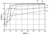
- FIG. 3 is a graph showing the relationship between the wavelength of laser light and reflectance.
- FIG. 4 is a graph showing temporal changes in the total output of laser light.
- FIG. 5A is a diagram showing a state in which the first laser beam is made incident on the first core.
- FIG. 5B is a diagram illustrating a state in which the first laser beam is emitted from the first core;
- FIG. 6A is a diagram showing a state in which the first laser light is made incident on the first core and the second core.
- FIG. 5A is a diagram showing a state in which the first laser beam is made incident on the first core and the second core.
- FIG. 6B is a diagram showing a state in which the first laser light is emitted from the first core and the second core
- FIG. 7A is a diagram showing a state in which the second laser beam is made incident on the first core and the first laser beam is made incident on the second core
- FIG. 7B is a diagram showing a state in which the first laser light is emitted from the second core while the second laser light is emitted from the first core.
- FIG. 8A is a diagram showing a state in which the output of the second laser beam to be incident on the first core is increased.
- FIG. 8B is a diagram showing a state in which the output of the second laser light is increased while moving the emission positions of the first laser light and the second laser light.
- the laser processing device 1 includes an optical coupling unit 10, a transmission fiber 20, a laser processing head 30, a robot 2, and a controller 5.
- the optical coupling unit 10 includes a first laser oscillator 11, a second laser oscillator 12, a first mirror 13, a second mirror 14, a third mirror 15, a first adjustment mechanism 16, and a second adjustment mechanism 17. and a third adjusting mechanism 18 .
- the first laser oscillator 11 emits the first laser beam L1 based on the command from the control unit 5.
- the first laser beam L1 is a short wavelength laser beam.
- the short-wavelength first laser light L1 is blue laser light or green laser light with a wavelength of 600 nm or less (for example, 266 nm to 600 nm).
- the first laser oscillator 11 emits a plurality of first laser beams L1 from a plurality of laser modules (not shown).
- the second laser oscillator 12 emits the second laser beam L2 based on the command from the control unit 5.
- the second laser beam L2 is a long-wavelength laser beam having a longer wavelength than the first laser beam L1.
- the long-wavelength second laser light L2 is infrared laser light with a wavelength of 800 nm or more (for example, about 800 nm to 16000 nm).
- the first mirror 13 reflects some of the first laser beams L1 emitted from the first laser oscillator 11 and guides them to the first adjustment mechanism 16 .
- the second mirror 14 reflects the remaining first laser beams L1 out of the plurality of first laser beams L1 emitted from the first laser oscillator 11 and guides them to the second adjustment mechanism 17 .
- the third mirror 15 reflects the second laser beam L2 emitted from the second laser oscillator 12 and guides it to the third adjustment mechanism 18 .
- the first adjustment mechanism 16 is composed of, for example, a two-axis MEMS (Micro Electro Mechanical Systems) mirror.
- the first adjustment mechanism 16 further reflects the first laser beam L ⁇ b>1 reflected by the first mirror 13 and guides it to the transmission fiber 20 .
- the first adjustment mechanism 16 changes the incident position of the first laser beam L1 with respect to the transmission fiber 20 by changing the angle of the mirror. This allows the first laser beam L1 to selectively enter the first core 21 or the second core 22 of the transmission fiber 20 .
- the second adjustment mechanism 17 is composed of, for example, a two-axis MEMS mirror.
- the second adjustment mechanism 17 further reflects the first laser beam L ⁇ b>1 reflected by the second mirror 14 and guides it to the transmission fiber 20 .
- the second adjustment mechanism 17 changes the incident position of the first laser beam L1 with respect to the transmission fiber 20 by changing the angle of the mirror. This allows the first laser beam L1 to selectively enter the first core 21 or the second core 22 of the transmission fiber 20 .
- the third adjustment mechanism 18 is composed of, for example, a two-axis MEMS mirror.
- the third adjustment mechanism 18 further reflects the second laser beam L2 reflected by the third mirror 15 and guides it to the transmission fiber 20 .
- the third adjustment mechanism 18 changes the incident position of the second laser beam L2 with respect to the transmission fiber 20 by changing the angle of the mirror. This allows the second laser light L2 to selectively enter the first core 21 or the second core 22 of the transmission fiber 20 .
- first adjustment mechanism 16, the second adjustment mechanism 17, and the third adjustment mechanism 18 may be configured using a biaxial galvanometer (galvanomirror) instead of the biaxial MEMS mirror.
- the optical coupling unit 10 and the laser processing head 30 are connected by a transmission fiber 20.
- the first laser beam L ⁇ b>1 and the second laser beam L ⁇ b>2 are transmitted to the laser processing head 30 via the transmission fiber 20 .
- the transmission fiber 20 has a first core 21 , a second core 22 , a first clad 23 , a second clad 24 and a protective coating 25 .
- the first core 21 is arranged at the axial center of the transmission fiber 20 .
- the first core 21 is formed in a circular shape when viewed from the axial direction.
- the first core 21 is made of quartz glass, for example.
- a first clad 23 is provided on the outer periphery of the first core 21 .
- the first clad 23 is provided coaxially with the first core 21 .
- the first clad 23 is made of a material having a lower refractive index than the first core 21 .
- the first clad 23 is made of, for example, fluorine-doped quartz glass. The refractive index of the first clad 23 is lower than that of the first core 21 .
- a second core 22 is provided on the outer periphery of the first clad 23 .
- the second core 22 is provided coaxially with the first core 21 .
- the second core 22 is formed in a ring shape when viewed from the axial direction.
- the second core 22 is made of the same material as the first core 21, such as quartz glass.
- the refractive index of the second core 22 is higher than that of the first clad 23 .
- a second clad 24 is provided on the outer periphery of the second core 22 .
- the second clad 24 is provided coaxially with the first core 21 and the second core 22 .
- the second clad 24 is made of, for example, fluorine-doped quartz glass.
- the refractive index of the second clad 24 is lower than that of the second core 22 .
- a protective film 25 is provided on the outer peripheral portion of the second clad 24 .
- the protective film 25 is made of synthetic resin, for example.
- the protective film 25 mechanically protects the first core 21, the second core 22, the first clad 23, and the second clad 24 made of quartz glass.
- the protective coating 25 prevents the first laser beam L1 and the second laser beam L2 from leaking from the transmission fiber 20 and prevents light from leaking into the transmission fiber 20 from the outside.
- the laser processing head 30 emits a first laser beam L1 and a second laser beam L2 incident from the transmission fiber 20 to the work W.
- the laser beam is emitted with the outer peripheral portion of the circular second laser beam L2 surrounded by the ring-shaped first laser beam L1.
- the laser processing head 30 has a collimator lens 31 , a fourth mirror 32 and a condenser lens 33 .
- the collimator lens 31 collimates the first laser beam L1 and the second laser beam L2 emitted from the emission end of the transmission fiber 20 .
- the fourth mirror 32 reflects the first laser beam L1 and the second laser beam L2 collimated by the collimator lens 31 and guides them to the condenser lens 33 .
- the condenser lens 33 condenses the first laser beam L1 and the second laser beam L2.
- the first laser beam L1 and the second laser beam L2 condensed by the condensing lens 33 are emitted to the work W. As shown in FIG.
- the robot 2 has a robot arm 3.
- a laser processing head 30 is attached to the tip of the robot arm 3 .
- the robot arm 3 has multiple joints 4 .
- the robot 2 changes the position of the laser processing head 30 with respect to the workpiece W by moving the laser processing head 30 along a predetermined welding direction (processing direction) based on a command from the control unit 5 .
- processing direction processing direction
- the emission positions of the first laser beam L1 and the second laser beam L2 with respect to the workpiece W are moved, and laser processing is performed.
- the controller 5 is connected to the optical coupling unit 10, the laser processing head 30, and the robot 2.
- the controller 5 controls the operations of the optical coupling unit 10 , the laser processing head 30 and the robot 2 .
- control unit 5 controls the output start and stop of the first laser beam L1 and the second laser beam L2, the output intensity of the first laser beam L1 and the second laser beam L2, and the like. It also has the function to In addition, although the control part 5 has one structure here, you may comprise more than one.
- the workpiece W is formed in a plate shape, for example.
- the workpiece W is composed of a high reflectance material with a low laser absorption rate.
- the reflectance of the laser beam differs depending on the material of the workpiece W.
- copper (Cu), aluminum (Al), gold (Au), and silver (Ag) are laser beams compared to iron (Fe).
- Fe iron
- the reflectance (%) of the wavelength of light is high, in other words, it is a high reflectance material with low laser absorptance.
- iron (Fe) has a relatively low reflectance (%) of the wavelength of the laser light, in other words, it is a low reflectance material with a high laser absorptivity.
- the work W is made of copper, which is a high reflectance material with a low laser absorptance.
- the workpiece W may be made of gold or silver.
- the laser start position S may generate spatter.
- control is performed at the laser start position S to suppress the occurrence of spatter in the laser start process.
- the laser start process is shown in FIG.
- the control section 5 performs the first step between the time T1 when the laser light emission is started at the laser start position S and the time T2.
- the controller 5 controls the operation of the optical coupling unit 10 so that the first core 21 emits the first laser beam L1.
- the controller 5 operates the short-wavelength first laser oscillator 11 to emit a short-wavelength first laser beam L1, while the long-wavelength second laser oscillator 12 is stopped.
- the control unit 5 adjusts the angle of the mirror of the first adjustment mechanism 16 to cause the first laser beam L1 reflected by the first mirror 13 to enter the first core 21 formed at the axial center of the transmission fiber 20.
- the control unit 5 adjusts the angle of the mirror of the second adjustment mechanism 17 to cause the first laser beam L reflected by the second mirror 14 to enter the first core 21 of the transmission fiber 20 .
- the short-wavelength first laser beam L1 incident on the first core 21 is emitted to the workpiece W in a circular shape.
- a molten pool 40 in which the workpiece W is partially melted by the first laser beam L1 is formed at the laser starting position S of the workpiece W.
- the output of the first laser beam L1 is set to 0.5 kW to 4 kW, preferably 2 kW.
- the controller 5 performs the fourth step between time T2 and time T3.
- the control section 5 controls the operation of the optical coupling unit 10 so that the first laser light L1 is emitted from both the first core 21 and the second core 22 .
- the controller 5 operates the first short-wavelength laser oscillator 11 to emit a first short-wavelength laser beam L1, while the second long-wavelength laser oscillator 12 to stop the operation of
- the control unit 5 adjusts the angle of the mirror of the first adjusting mechanism 16 to cause the first laser beam L1 reflected by the first mirror 13 to enter the first core 21 of the transmission fiber 20 .
- the control unit 5 adjusts the angle of the mirror of the second adjustment mechanism 17 to cause the first laser beam L1 reflected by the second mirror 14 to enter the second core 22 .
- the short-wavelength first laser beam L incident on the first core 21 is emitted to the workpiece W in a circular shape.
- the short-wavelength first laser beam L1 that has entered the second core 22 is emitted toward the workpiece W in a ring shape.
- the beam diameter of the first laser beam L1 in the fourth step is the beam diameter of the first laser beam L1 in the first step ( 5B).
- a molten pool 40 larger than that in the first step is formed at the laser starting position S of the workpiece W.
- the emission range of the first laser beam L1 at the laser start position S is widened, and the power density of the laser is relatively lowered compared to the first step.
- the workpiece W can also be preheated.
- the control unit 5 performs the second step.
- the controller 5 causes the first core 21 to emit the long-wavelength second laser beam L2 and the second core 22 to emit the short-wavelength first laser beam L1. It controls the operation of the coupling unit 10 .
- the controller 5 operates the first short-wavelength laser oscillator 11 to emit a first short-wavelength laser beam L1, while the second long-wavelength laser oscillator 12 is operated to emit the long-wavelength second laser beam L2.
- the control unit 5 adjusts the angle of the mirror of the first adjustment mechanism 16 to direct the first short-wavelength laser light L1 reflected by the first mirror 13 to be coaxial with the first core 21 of the transmission fiber 20 and at the same position as the first laser beam L1.
- the light is made incident on the second core 22 provided on the outer peripheral side of the first core 21 .
- the controller 5 adjusts the angle of the mirror of the second adjustment mechanism 17 to cause the first short-wavelength laser beam L1 reflected by the second mirror 14 to enter the second core 22 of the transmission fiber 20 .
- the control unit 5 adjusts the angle of the mirror of the third adjustment mechanism 18 to direct the second long-wavelength laser beam L2 reflected by the third mirror 15 to the first core 21 provided at the axial center of the transmission fiber 20. be incident on the
- the long-wavelength second laser beam L2 incident on the first core 21 provided at the axial center of the transmission fiber 20 is emitted to the workpiece W in a circular shape. be.
- the short-wavelength first laser beam L1 that has entered the second core 22 is emitted toward the workpiece W in a ring shape.
- a molten pool 40 is formed with a large amount of penetration due to the high output of the long-wavelength second laser beam L2.
- the output of the second laser beam L2 is set to 4 kW, for example.
- the beam diameter of the short-wavelength first laser beam L1 is reduced with respect to the workpiece W made of the highly reflective material, and the workpiece W is partially melted to form the Then, the beam diameter of the first laser beam L1 is increased, and the power density of the laser is relatively lowered to promote preheating of the work W. As shown in FIG.
- the molten pool 40 of the workpiece W is subjected to a long A second laser beam L2 with a wavelength is emitted, and a first laser beam L1 with a short wavelength is emitted in a ring shape around the laser beam L1 to form a molten pool 40 with a large amount of penetration.
- the amount of penetration is increased, and the opening of the keyhole (not shown) formed in the molten pool 40 is widened by widening the inclination of the peripheral edge of the opening of the keyhole, thereby stabilizing the molten metal vapor in the keyhole.
- the generation of spatter at the laser start position S in the laser start process can be suppressed, and the processing quality of the work W can be improved.
- the second it is possible to clean the processing surface behind the second laser beam L2 while preheating the front portion of the laser beam L2.
- the control unit 5 performs the third step between time T3 and time T4.
- the control unit 5 causes the first core 21 provided at the axial center of the transmission fiber 20 to emit the second laser light L2 having a long wavelength, while the second laser light L2 provided on the outer periphery of the first core 21
- the operation of the optical coupling unit 10 is controlled so that the short wavelength first laser light L1 is emitted from the two cores 22 .
- the control unit 5 gradually increases the output of the long-wavelength second laser beam L2 emitted from the first core 21 provided at the axial center of the transmission fiber 20. increase.
- the controller 5 operates the first laser oscillator 11 to emit the first laser beam L1, and operates the second laser oscillator 12 to emit the second laser beam L2. is emitted.
- the control unit 5 adjusts the angle of the mirror of the first adjustment mechanism 16 to direct the first short-wavelength laser light L1 reflected by the first mirror 13 to be coaxial with the first core 21 of the transmission fiber 20 and at the same position as the first laser beam L1.
- the light is made incident on the second core 22 provided on the outer peripheral side of the first core 21 .
- the controller 5 adjusts the angle of the mirror of the second adjustment mechanism 17 to cause the first short-wavelength laser beam L1 reflected by the second mirror 14 to enter the second core 22 of the transmission fiber 20 .
- the controller 5 adjusts the angle of the mirror of the third adjusting mechanism 18 to cause the second long-wavelength laser beam L2 reflected by the third mirror 15 to enter the first core 21 of the transmission fiber 20 .
- the long-wavelength second laser beam L2 incident on the first core 21 provided at the axial center of the transmission fiber 20 is emitted to the workpiece W in a circular shape. be.
- the short-wavelength first laser beam L1 that has entered the second core 22 is emitted toward the workpiece W in a ring shape.
- the control unit 5 controls the operation of the second laser oscillator 12 to increase the output of the second long-wavelength laser beam L2 incident on the first core 21 .
- the output of the second laser beam L2 is set to 10 kW, for example.
- the output of the second laser beam L2 at time T4 is greater than the output of the second laser beam L2 at time T3. Therefore, the total output P2 of the laser light at time T4 is larger than the total output P1 of the laser light at time T3.
- the control unit 5 controls the operation of the second laser oscillator 12 so that the total output of laser light gradually changes from P1 to P2 from time T3 to time T4.
- a molten pool 40 is formed in the work W at the position where the first short-wavelength laser beam L1 and the second long-wavelength laser beam L2 are emitted.
- a weld bead 41 is formed on the workpiece W behind the molten pool 40 in the welding direction by the solidification of the molten pool 40 .
- the output of the laser light is gradually increased.
- a sufficient penetration depth of the workpiece W can be ensured while moving the machining head 30 in the welding direction.
- the embodiment may be configured as follows.
- the first step of emitting the short-wavelength first laser beam L1 from the first core 21 is performed between the time T1 and the time T2, and the short-wavelength first laser beam L1 is emitted between the time T2 and the time T3.
- a fourth step of emitting the laser light L1 from the first core 21 and the second core 22 is performed, and at time T3, the short wavelength first laser light L1 is emitted from the second core 22, while the long wavelength second laser light L1
- a second step of emitting the light L2 from the first core 21 is performed, and between time T3 and time T4, the emission positions of the first laser light L1 and the second laser light L2 with respect to the workpiece W are moved in the laser processing direction.
- the third step of gradually increasing the output of the second laser beam L2 emitted from the first core 21 is performed, but the present invention is not limited to this form.
- the second step may be performed without performing the fourth step. That is, the first step may be performed between time T1 and time T3, the second step may be performed at time T3, and the third step may be performed between time T3 and time T4.
- the robot 2 moves the laser processing head 30 to change the position of the laser processing head 30 with respect to the work W, but the present invention is not limited to this form.
- the work W may be mounted on a moving table (not shown), and the work W may be moved relative to the laser processing head 30 .
- the laser processing head 30 and the moving table on which the work W is mounted are relatively moved, and the first laser beam L1 and the second laser beam L2 are moved relatively to the work W for processing.
- the present invention is not limited to this configuration.
- a configuration in which a laser processing head that emits the short-wavelength first laser beam L1 and a laser processing head that emits the long-wavelength second laser beam L2 are provided separately may be used.
- the present invention has a highly practical effect of being able to suppress the occurrence of spatter at the laser start position, so it is extremely useful and has high industrial applicability.
Landscapes
- Physics & Mathematics (AREA)
- Optics & Photonics (AREA)
- Engineering & Computer Science (AREA)
- Plasma & Fusion (AREA)
- Mechanical Engineering (AREA)
- Laser Beam Processing (AREA)
Abstract
伝送ファイバ20は、第1コア21と、第2コア22とを有する。第2コア22は、第1コア21の外周部に設けられる。レーザ開始工程の第1工程では、第1コア21から第1レーザ光L1を出射する。第2工程では、第2コア22から第1レーザ光L1を出射する一方、第1コア21から第2レーザ光L2を出射する。第3工程では、第1レーザ光L1及び第2レーザ光L2のワークWに対する出射位置をレーザ加工方向に移動させながら、第1コア21から出射させる第2レーザ光L2の出力を徐々に増加する。
Description
本発明は、レーザ加工方法に関するものである。
特許文献1には、第1レーザビームをダブルコアファイバの第1ファイバコアに入射する一方、第1レーザビームとは異なる波長の第2レーザビームを第2ファイバコアに入射して、ワークに対して第1レーザビーム及び第2レーザビームを出射するようにしたレーザ切断方法が開示されている。
ところで、従来の発明では、レーザ開始位置において、第1レーザビーム及び第2レーザビームをワークに対して同時に出射すると、レーザ出力が高くなりすぎることでスパッタが発生してしまい、ワークの加工品質が低下するおそれがある。
本発明は、かかる点に鑑みてなされたものであり、その目的は、レーザ開始位置においてスパッタの発生を抑えることにある。
第1の態様は、伝送ファイバで伝送されたレーザ光を出射してワークを加工するレーザ加工方法であって、前記伝送ファイバは、第1コアと、該第1コアの外周部に設けられた第2コアとを少なくとも有し、前記レーザ光は、第1レーザ光と、該第1レーザ光よりも波長の長い第2レーザ光とを含み、前記ワークの加工開始時に、前記第1レーザ光及び前記第2レーザ光の出力を調整するレーザ開始工程を備え、前記レーザ開始工程は、前記第1レーザ光を前記第1コアから出射させる第1工程と、前記第1レーザ光を前記第2コアから出射させる一方、前記第2レーザ光を前記第1コアから出射させる第2工程と、前記第1レーザ光及び前記第2レーザ光の前記ワークに対する出射位置をレーザ加工方向に移動させながら、前記第1コアから出射させる該第2レーザ光の出力を徐々に増加させる第3工程とを有することを特徴とする。
第1の態様では、伝送ファイバは、第1コアと、第2コアとを少なくとも有する。第2コアは、第1コアの外周部に設けられる。レーザ開始工程の第1工程では、第1コアから第1レーザ光を出射する。第2工程では、第2コアから第1レーザ光を出射する一方、第1コアから第2レーザ光を出射する。第3工程では、第1レーザ光及び第2レーザ光のワークに対する出射位置をレーザ加工方向に移動させながら、第1コアから出射させる第2レーザ光の出力を徐々に増加する。
このように、レーザ開始位置において、第1レーザ光でワークを予熱した後に、第2レーザ光を出射することで、レーザ開始位置におけるスパッタの発生を抑え、ワークの加工品質を高めることができる。
また、第1コアから出射した第2レーザ光の周囲に、第2コアを通過してリング状となった第1レーザ光を出射することで、第2レーザ光の前方を予熱しつつ、第2レーザ光の後方の加工表面をきれいにすることができる。
第2の態様は、第1の態様において、前記第2工程の前に、前記第1レーザ光を前記第1コア及び前記第2コアから出射させる第4工程を有することを特徴とする。
第2の態様では、第2レーザ光をワークに出射する前に、第1レーザ光を第1コア及び第2コアから出射してワークの予熱範囲を広げることで、ワークの加工品質を高めることができる。
本開示の態様によれば、レーザ開始位置においてスパッタの発生を抑えることができる。
以下、本発明の実施形態を図面に基づいて説明する。なお、以下の好ましい実施形態の説明は、本質的に例示に過ぎず、本発明、その適用物或いはその用途を制限することを意図するものではない。
図1に示すように、レーザ加工装置1は、光結合ユニット10と、伝送ファイバ20と、レーザ加工ヘッド30と、ロボット2と、制御部5とを備える。
光結合ユニット10は、第1レーザ発振器11と、第2レーザ発振器12と、第1ミラー13と、第2ミラー14と、第3ミラー15と、第1調整機構16と、第2調整機構17と、第3調整機構18とを有する。
第1レーザ発振器11は、制御部5からの指令に基づいて、第1レーザ光L1を出射する。第1レーザ光L1は、短波長のレーザ光である。短波長の第1レーザ光L1は、波長が600nm以下(例えば、266nm~600nm)の青色レーザ光又は緑色レーザ光である。第1レーザ発振器11は、図示しない複数のレーザモジュールから複数の第1レーザ光L1を出射する。
第2レーザ発振器12は、制御部5からの指令に基づいて、第2レーザ光L2を出射する。第2レーザ光L2は、第1レーザ光L1よりも波長の長い、長波長のレーザ光である。長波長の第2レーザ光L2は、波長が800nm以上(例えば、800nm~16000nm程度)の赤外レーザ光である。
第1ミラー13は、第1レーザ発振器11から出射された複数の第1レーザ光L1のうち一部の第1レーザ光L1を反射して、第1調整機構16に導光する。
第2ミラー14は、第1レーザ発振器11から出射された複数の第1レーザ光L1のうち残りの第1レーザ光L1を反射して、第2調整機構17に導光する。
第3ミラー15は、第2レーザ発振器12から出射された第2レーザ光L2を反射して、第3調整機構18に導光する。
第1調整機構16は、例えば、2軸MEMS(Micro Electro Mechanical Systems)ミラーで構成される。第1調整機構16は、第1ミラー13で反射された第1レーザ光L1をさらに反射して、伝送ファイバ20に導光する。第1調整機構16は、ミラーの角度を変更することで、伝送ファイバ20に対する第1レーザ光L1の入射位置を変更する。これにより、第1レーザ光L1を、伝送ファイバ20の第1コア21又は第2コア22に対して選択的に入射可能となっている。
第2調整機構17は、例えば、2軸MEMSミラーで構成される。第2調整機構17は、第2ミラー14で反射された第1レーザ光L1をさらに反射して、伝送ファイバ20に導光する。第2調整機構17は、ミラーの角度を変更することで、伝送ファイバ20に対する第1レーザ光L1の入射位置を変更する。これにより、第1レーザ光L1を、伝送ファイバ20の第1コア21又は第2コア22に対して選択的に入射可能となっている。
第3調整機構18は、例えば、2軸MEMSミラーで構成される。第3調整機構18は、第3ミラー15で反射された第2レーザ光L2をさらに反射して、伝送ファイバ20に導光する。第3調整機構18は、ミラーの角度を変更することで、伝送ファイバ20に対する第2レーザ光L2の入射位置を変更する。これにより、第2レーザ光L2を、伝送ファイバ20の第1コア21又は第2コア22に対して選択的に入射可能となっている。
なお、第1調整機構16、第2調整機構17、及び第3調整機構18は、2軸MEMSミラーの代わりに、2軸のガルバノメータ(ガルバノミラー)を用いた構成としてもよい。
光結合ユニット10とレーザ加工ヘッド30とは、伝送ファイバ20で接続される。第1レーザ光L1及び第2レーザ光L2は、伝送ファイバ20を介してレーザ加工ヘッド30に伝送される。
図2にも示すように、伝送ファイバ20は、第1コア21と、第2コア22と、第1クラッド23と、第2クラッド24と、保護皮膜25とを有する。
第1コア21は、伝送ファイバ20の軸心に配置される。第1コア21は、軸方向から見て円形状に形成される。第1コア21は、例えば、石英ガラスで形成される。
第1コア21の外周部には、第1クラッド23が設けられる。第1クラッド23は、第1コア21と同軸に設けられる。第1クラッド23は、第1コア21よりも屈折率の低い材料で形成される。第1クラッド23は、例えば、フッ素がドープされた石英ガラスで構成される。第1クラッド23の屈折率は、第1コア21の屈折率よりも低い。
第1クラッド23の外周部には、第2コア22が設けられる。第2コア22は、第1コア21と同軸に設けられる。第2コア22は、軸方向から見てリング状に形成される。第2コア22は、第1コア21と同じ材質、例えば、石英ガラスで構成される。第2コア22の屈折率は、第1クラッド23の屈折率よりも高い。
第2コア22の外周部には、第2クラッド24が設けられる。第2クラッド24は、第1コア21及び第2コア22と同軸に設けられる。第2クラッド24は、例えば、フッ素がドープされた石英ガラスで構成される。第2クラッド24の屈折率は、第2コア22の屈折率よりも低い。
第2クラッド24の外周部には、保護皮膜25が設けられる。保護皮膜25は、例えば、合成樹脂で構成される。保護皮膜25は、石英ガラスで構成された第1コア21、第2コア22、第1クラッド23、及び第2クラッド24を機械的に保護する。保護皮膜25は、伝送ファイバ20から第1レーザ光L1及び第2レーザ光L2が漏れ出すことや、外部から伝送ファイバ20に光が漏れ込むのを抑える。
図1に示すように、レーザ加工ヘッド30は、伝送ファイバ20から入射される第1レーザ光L1及び第2レーザ光L2をワークWに出射する。図1に示す例では、円形状の第2レーザ光L2の外周部が、リング状の第1レーザ光L1で囲まれた状態で、レーザ光が出射される。
レーザ加工ヘッド30は、コリメートレンズ31と、第4ミラー32と、集光レンズ33とを有する。
コリメートレンズ31は、伝送ファイバ20の出射端から出射された第1レーザ光L1及び第2レーザ光L2を平行化する。
第4ミラー32は、コリメートレンズ31で平行化された第1レーザ光L1及び第2レーザ光L2を反射して、集光レンズ33に導光する。
集光レンズ33は、第1レーザ光L1及び第2レーザ光L2を集光する。集光レンズ33で集光された第1レーザ光L1及び第2レーザ光L2は、ワークWに出射される。
ロボット2は、ロボットアーム3を有する。ロボットアーム3の先端部には、レーザ加工ヘッド30が取り付けられる。ロボットアーム3は、複数の関節部4を有する。
ロボット2は、制御部5からの指令に基づいて、レーザ加工ヘッド30を所定の溶接方向(加工方向)に沿って移動させ、ワークWに対するレーザ加工ヘッド30の位置を変更する。これにより、ワークWに対する第1レーザ光L1及び第2レーザ光L2の出射位置を移動させ、レーザ加工を行う。
制御部5は、光結合ユニット10、レーザ加工ヘッド30、及びロボット2に接続される。制御部5は、光結合ユニット10、レーザ加工ヘッド30、及びロボット2の動作を制御する。
制御部5は、レーザ加工ヘッド30の移動速度の他に、第1レーザ光L1及び第2レーザ光L2の出力開始や停止、第1レーザ光L1及び第2レーザ光L2の出力強度などを制御する機能も備える。なお、制御部5は、ここで1つの構成になっているが、複数で構成しても良い。
ワークWは、例えば板状に形成される。ワークWは、レーザ吸収率の低い高反射率材料で構成される。具体的に、図3に示すように、レーザ光の反射率は、ワークWの材質によって異なる。例えば、波長が800nm以上の長波長としての赤外レーザ光を基準とした場合、銅(Cu)、アルミニウム(Al)、金(Au)、銀(Ag)は、鉄(Fe)に比べてレーザ光の波長の反射率(%)が高く、言い換えるとレーザ吸収率の低い高反射率材料であることが分かる。一方、鉄(Fe)は、相対的にレーザ光の波長の反射率(%)が低く、言い換えるとレーザ吸収率の高い低反射率材料であることが分かる。
そこで、本実施形態では、ワークWをレーザ吸収率の低い高反射率材料である銅で構成している。なお、ワークWを金又は銀で構成してもよい。
〈レーザ開始位置における動作について〉
ところで、ワークWの溶接開始点であるレーザ開始位置Sにおいて、レーザ開始工程でのレーザ照射開始時に、第1レーザ光L1及び第2レーザ光L2をワークWに対して同時に出射すると、レーザ開始位置Sでスパッタが発生するおそれがある。
ところで、ワークWの溶接開始点であるレーザ開始位置Sにおいて、レーザ開始工程でのレーザ照射開始時に、第1レーザ光L1及び第2レーザ光L2をワークWに対して同時に出射すると、レーザ開始位置Sでスパッタが発生するおそれがある。
そこで、本実施形態のレーザ加工装置1では、レーザ開始位置Sにおいて、レーザ開始工程でのスパッタの発生を抑えるための制御を行うようにした。
具体的に、レーザ開始工程を図4に示す。このように、レーザ開始位置Sでレーザ光の出射を開始したときの時刻T1から時刻T2の間において、制御部5は、第1工程を行う。第1工程では、制御部5は、第1コア21から第1レーザ光L1が出射されるように、光結合ユニット10の動作を制御する。
第1工程において、図5Aに示すように、制御部5は、短波長の第1レーザ発振器11を動作させて、短波長の第1レーザ光L1を出射させる一方、長波長の第2レーザ発振器12の動作を停止させる。制御部5は、第1調整機構16のミラーの角度を調整して、第1ミラー13で反射された第1レーザ光L1を伝送ファイバ20の軸心に構成された第1コア21に入射させる。さらに、制御部5は、第2調整機構17のミラーの角度を調整して、第2ミラー14で反射された第1レーザ光Lを伝送ファイバ20の第1コア21に入射させる。
図5Bに示すように、第1コア21に入射された短波長の第1レーザ光L1は、ワークWに対して円形状に出射される。ワークWのレーザ開始位置Sには、第1レーザ光L1によりワークWが一部溶融した溶融池40が形成される。このように、短波長の第1レーザ光L1のビーム径を小さくしてレーザのパワー密度を上げてワークWに出射することで、レーザ開始位置Sでの高反射材料のワークWを短い時間で溶融させることができる。ここで、第1レーザ光L1の出力は、0.5kW~4kW、好ましくは、2kWに設定する。
図4に示すように、時刻T2から時刻T3の間において、制御部5は、第4工程を行う。第4工程では、制御部5は、第1コア21及び第2コア22の両方から第1レーザ光L1が出射されるように、光結合ユニット10の動作を制御する。
第4工程において、図6Aに示すように、制御部5は、短波長の第1レーザ発振器11を動作させて短波長の第1レーザ光L1を出射させる一方、長波長の第2レーザ発振器12の動作を停止させる。制御部5は、第1調整機構16のミラーの角度を調整して、第1ミラー13で反射された第1レーザ光L1を伝送ファイバ20の第1コア21に入射させる。さらに、制御部5は、第2調整機構17のミラーの角度を調整して、第2ミラー14で反射された第1レーザ光L1を第2コア22に入射させる。
図6Bに示すように、第1コア21に入射された短波長の第1レーザ光Lは、ワークWに対して円形状に出射される。第2コア22に入射された短波長の第1レーザ光L1は、ワークWに対してリング状に出射される。第1コア21及び第2コア22から出射された第1レーザ光L1が合わさることで、第4工程における第1レーザ光L1のビーム径は、第1工程における第1レーザ光L1のビーム径(図5B参照)よりも大きくなる。第4工程において、ワークWのレーザ開始位置Sには、第1工程時よりも大きな溶融池40が形成される。このように、第1レーザ光L1のビーム径を大きくすることで、レーザ開始位置Sにおける第1レーザ光L1の出射範囲が広がり、また第1工程に比べてレーザのパワー密度を相対的に下げてワークWの予熱も行うことができる。
図4に示すように、時刻T3において、制御部5は、第2工程を行う。第2工程では、制御部5は、第1コア21から長波長の第2レーザ光L2が出射される一方、第2コア22から短波長の第1レーザ光L1が出射されるように、光結合ユニット10の動作を制御する。
第2工程において、図7Aに示すように、制御部5は、短波長の第1レーザ発振器11を動作させて短波長の第1レーザ光L1を出射させる一方、長波長の第2レーザ発振器12を動作させて長波長の第2レーザ光L2を出射させる。
制御部5は、第1調整機構16のミラーの角度を調整して、第1ミラー13で反射された短波長の第1レーザ光L1を、伝送ファイバ20の第1コア21と同軸で且つ第1コア21の外周側に設けられた第2コア22に入射させる。制御部5は、第2調整機構17のミラーの角度を調整して、第2ミラー14で反射された短波長の第1レーザ光L1を伝送ファイバ20の第2コア22に入射させる。制御部5は、第3調整機構18のミラーの角度を調整して、第3ミラー15で反射された長波長の第2レーザ光L2を伝送ファイバ20の軸心に設けられた第1コア21に入射させる。
第2工程において、図7Bに示すように、伝送ファイバ20の軸心に設けられた第1コア21に入射された長波長の第2レーザ光L2は、ワークWに対して円形状に出射される。第2コア22に入射された短波長の第1レーザ光L1は、ワークWに対してリング状に出射される。ワークWのレーザ開始位置Sには、長波長の第2レーザ光L2の高出力によって溶け込み量が大きくなった溶融池40が形成される。ここで、第2レーザ光L2の出力は、例えば、4kWに設定する。
このように、第1工程、第4工程において、高反射材料のワークWに対して、短波長の第1レーザ光L1のビーム径を小さくして、ワークWの一部が溶融して形成された溶融池40を形成し、次に第1レーザ光L1のビーム径を大きくして、レーザのパワー密度を相対的に下げてワークWの予熱を促進する。その後に、溶融金属で形成される溶融池40により、高反射材料のワークWの表面のレーザ吸収率が相対的に上がった状態で、第2工程において、ワークWの溶融池40に対し、長波長の第2レーザ光L2を出射し、その外周にリング状に、短波長の第1レーザ光L1を出射し、溶け込み量が大きくなった溶融池40を形成する。
これにより、溶け込み量を大きくするとともに、溶融池40に形成される図示しないキーホールの開口の周縁の傾斜を押し広げるようにしてキーホールの開口を押し広げ、キーホール内の金属溶融蒸気の安定した排出を促進し、キーホールの崩落を抑制することで、レーザ開始工程でのレーザ開始位置Sにおけるスパッタの発生を抑え、ワークWの加工品質を高めることができる。
また、第1コア21から出射した長波長の第2レーザ光L2の周囲に、第2コア22を通過してリング状となった短波長の第1レーザ光L1を出射することで、第2レーザ光L2の前方を予熱しつつ、第2レーザ光L2の後方の加工表面をきれいにすることができる。
図4に示すように、時刻T3から時刻T4の間において、制御部5は、第3工程を行う。第3工程では、制御部5は、伝送ファイバ20の軸心に設けられた第1コア21から長波長の第2レーザ光L2が出射される一方、第1コア21の外周に設けられた第2コア22から短波長の第1レーザ光L1が出射されるように、光結合ユニット10の動作を制御する。また、制御部5は、レーザ加工ヘッド30を溶接方向に移動させながら、伝送ファイバ20の軸心に設けられた第1コア21から出射される長波長の第2レーザ光L2の出力を徐々に増加させる。
第3工程において、図8Aに示すように、制御部5は、第1レーザ発振器11を動作させて第1レーザ光L1を出射させる一方、第2レーザ発振器12を動作させて第2レーザ光L2を出射させる。
制御部5は、第1調整機構16のミラーの角度を調整して、第1ミラー13で反射された短波長の第1レーザ光L1を、伝送ファイバ20の第1コア21と同軸で且つ第1コア21の外周側に設けられた第2コア22に入射させる。制御部5は、第2調整機構17のミラーの角度を調整して、第2ミラー14で反射された短波長の第1レーザ光L1を伝送ファイバ20の第2コア22に入射させる。制御部5は、第3調整機構18のミラーの角度を調整して、第3ミラー15で反射された長波長の第2レーザ光L2を、伝送ファイバ20の第1コア21に入射させる。
第3工程において、図8Bに示すように、伝送ファイバ20の軸心に設けられた第1コア21に入射された長波長の第2レーザ光L2は、ワークWに対して円形状に出射される。第2コア22に入射された短波長の第1レーザ光L1は、ワークWに対してリング状に出射される。制御部5は、第2レーザ発振器12の動作を制御して、第1コア21に入射される長波長の第2レーザ光L2の出力を増加させる。ここで、第2レーザ光L2の出力は、例えば、10kWに設定する。
具体的に、図4に示すように、時刻T4における第2レーザ光L2の出力は、時刻T3における第2レーザ光L2の出力よりも大きくなっている。そのため、時刻T3におけるレーザ光の総出力P1よりも、時刻T4におけるレーザ光の総出力P2の方が大きくなる。制御部5は、時刻T3から時刻T4にかけて、レーザ光の総出力がP1からP2に徐々に変化するように、第2レーザ発振器12の動作を制御する。ワークWには、短波長の第1レーザ光L1及び長波長の第2レーザ光L2のワークWに対する出射位置に溶融池40が形成される。ワークWにおける溶融池40よりも溶接方向の後方には、溶融池40が凝固することで溶接ビード41が形成される。
このように、レーザ開始工程の第3工程において、レーザ加工ヘッド30を溶接方向に移動させながら、レーザ光の出力を徐々に増加させることで、レーザ開始位置Sにおけるスパッタの発生を抑えつつ、レーザ加工ヘッド30を溶接方向に移動させながら、ワークWの溶け込み深さを十分に確保することができる。
《その他の実施形態》
前記実施形態については、以下のような構成としてもよい。
前記実施形態については、以下のような構成としてもよい。
本実施形態では、時刻T1から時刻T2の間において、短波長の第1レーザ光L1を第1コア21から出射させる第1工程を行い、時刻T2から時刻T3の間において、短波長の第1レーザ光L1を第1コア21及び第2コア22から出射させる第4工程を行い、時刻T3において、短波長の第1レーザ光L1を第2コア22から出射させる一方、長波長の第2レーザ光L2を第1コア21から出射させる第2工程を行い、時刻T3から時刻T4の間において、第1レーザ光L1及び第2レーザ光L2のワークWに対する出射位置をレーザ加工方向に移動させながら、第1コア21から出射させる第2レーザ光L2の出力を徐々に増加させる第3工程を行うようにしたが、この形態に限定するものではない。
例えば、第1工程の後、第4工程を行うことなく、第2工程を行うようにしてもよい。つまり、時刻T1から時刻T3の間において第1工程を行い、時刻T3において第2工程を行い、時刻T3から時刻T4の間において第3工程を行うようにしてもよい。
本実施形態では、ロボット2でレーザ加工ヘッド30を移動させ、ワークWに対するレーザ加工ヘッド30の位置を変更するようにしたが、この形態に限定するものではない。例えば、ワークWを移動テーブル(図示省略)に搭載して、レーザ加工ヘッド30に対して、ワークWを相対的に移動させる構成であってもよい。
また、レーザ加工ヘッド30とワークWを搭載した移動テーブルとを相対的に移動させ、ワークWに対して相対的に第1レーザ光L1及び第2レーザ光L2を移動させて加工する構成であっても良い。
本実施形態では、1つのレーザ加工ヘッド30から短波長の第1レーザ光L1及び長波長の第2レーザ光L2を出射するようにした形態について説明したが、この形態に限定するものではない。例えば、短波長の第1レーザ光L1を出射するレーザ加工ヘッドと、長波長の第2レーザ光L2を出射するレーザ加工ヘッドとを別々に設けた構成であってもよい。
以上説明したように、本発明は、レーザ開始位置においてスパッタの発生を抑えることができるという実用性の高い効果が得られることから、きわめて有用で産業上の利用可能性は高い。
1 レーザ加工装置
2 ロボット
5 制御部
11 第1レーザ発振器
12 第2レーザ発振器
16 第1調整機構
17 第2調整機構
18 第3調整機構
20 伝送ファイバ
21 第1コア
22 第2コア
L1 第1レーザ光
L2 第2レーザ光
W ワーク
2 ロボット
5 制御部
11 第1レーザ発振器
12 第2レーザ発振器
16 第1調整機構
17 第2調整機構
18 第3調整機構
20 伝送ファイバ
21 第1コア
22 第2コア
L1 第1レーザ光
L2 第2レーザ光
W ワーク
Claims (2)
- 伝送ファイバで伝送されたレーザ光を出射してワークを加工するレーザ加工方法であって、
前記伝送ファイバは、第1コアと、該第1コアの外周部に設けられた第2コアとを少なくとも有し、
前記レーザ光は、第1レーザ光と、該第1レーザ光よりも波長の長い第2レーザ光とを含み、
前記ワークの加工開始時に、前記第1レーザ光及び前記第2レーザ光の出力を調整するレーザ開始工程を備え、
前記レーザ開始工程は、
前記第1レーザ光を前記第1コアから出射させる第1工程と、
前記第1レーザ光を前記第2コアから出射させる一方、前記第2レーザ光を前記第1コアから出射させる第2工程と、
前記第1レーザ光及び前記第2レーザ光の前記ワークに対する出射位置をレーザ加工方向に移動させながら、前記第1コアから出射させる該第2レーザ光の出力を徐々に増加させる第3工程とを有する
ことを特徴とするレーザ加工方法。 - 請求項1において、
前記第2工程の前に、前記第1レーザ光を前記第1コア及び前記第2コアから出射させる第4工程を有する
ことを特徴とするレーザ加工方法。
Priority Applications (2)
| Application Number | Priority Date | Filing Date | Title |
|---|---|---|---|
| CN202380018611.6A CN118660780A (zh) | 2022-02-02 | 2023-02-01 | 激光加工方法 |
| JP2023578577A JPWO2023149449A1 (ja) | 2022-02-02 | 2023-02-01 |
Applications Claiming Priority (2)
| Application Number | Priority Date | Filing Date | Title |
|---|---|---|---|
| JP2022014611 | 2022-02-02 | ||
| JP2022-014611 | 2022-02-02 |
Publications (1)
| Publication Number | Publication Date |
|---|---|
| WO2023149449A1 true WO2023149449A1 (ja) | 2023-08-10 |
Family
ID=87552415
Family Applications (1)
| Application Number | Title | Priority Date | Filing Date |
|---|---|---|---|
| PCT/JP2023/003153 WO2023149449A1 (ja) | 2022-02-02 | 2023-02-01 | レーザ加工方法 |
Country Status (3)
| Country | Link |
|---|---|
| JP (1) | JPWO2023149449A1 (ja) |
| CN (1) | CN118660780A (ja) |
| WO (1) | WO2023149449A1 (ja) |
Citations (3)
| Publication number | Priority date | Publication date | Assignee | Title |
|---|---|---|---|---|
| WO2017134964A1 (ja) * | 2016-02-05 | 2017-08-10 | 村田機械株式会社 | レーザ加工機およびレーザ加工方法 |
| JP2018174059A (ja) * | 2017-03-31 | 2018-11-08 | パナソニックIpマネジメント株式会社 | 溶接構造体及びその製造方法 |
| WO2019176502A1 (ja) * | 2018-03-15 | 2019-09-19 | パナソニックIpマネジメント株式会社 | レーザ発振器、それを用いたレーザ加工装置及びレーザ発振方法 |
-
2023
- 2023-02-01 WO PCT/JP2023/003153 patent/WO2023149449A1/ja unknown
- 2023-02-01 CN CN202380018611.6A patent/CN118660780A/zh active Pending
- 2023-02-01 JP JP2023578577A patent/JPWO2023149449A1/ja active Pending
Patent Citations (3)
| Publication number | Priority date | Publication date | Assignee | Title |
|---|---|---|---|---|
| WO2017134964A1 (ja) * | 2016-02-05 | 2017-08-10 | 村田機械株式会社 | レーザ加工機およびレーザ加工方法 |
| JP2018174059A (ja) * | 2017-03-31 | 2018-11-08 | パナソニックIpマネジメント株式会社 | 溶接構造体及びその製造方法 |
| WO2019176502A1 (ja) * | 2018-03-15 | 2019-09-19 | パナソニックIpマネジメント株式会社 | レーザ発振器、それを用いたレーザ加工装置及びレーザ発振方法 |
Also Published As
| Publication number | Publication date |
|---|---|
| JPWO2023149449A1 (ja) | 2023-08-10 |
| CN118660780A (zh) | 2024-09-17 |
Similar Documents
| Publication | Publication Date | Title |
|---|---|---|
| JP6602860B2 (ja) | レーザ加工装置及びレーザ加工方法 | |
| JP6887502B2 (ja) | レーザ加工装置および方法 | |
| TWI789466B (zh) | 雷射焊接裝置及使用雷射束焊接工件的方法 | |
| WO2012050098A1 (ja) | レーザ加工装置及びレーザ加工方法 | |
| JP6393555B2 (ja) | レーザ加工機及びレーザ切断加工方法 | |
| WO2023149449A1 (ja) | レーザ加工方法 | |
| WO2023149451A1 (ja) | レーザ加工方法 | |
| JP2020199513A (ja) | レーザ加工機及びレーザ加工機の制御方法 | |
| JP6416801B2 (ja) | 加工ヘッドのアプローチ機能を有するレーザ加工機 | |
| JP7382552B2 (ja) | レーザ加工装置及びそれを用いたレーザ加工方法 | |
| JP2023112736A (ja) | レーザ加工装置 | |
| WO2021107043A1 (ja) | レーザ加工装置 | |
| JP2023112733A (ja) | レーザ加工方法 | |
| JP7554973B2 (ja) | レーザ加工装置 | |
| JP2023112731A (ja) | レーザ加工装置 | |
| JP2023112732A (ja) | レーザ加工装置 | |
| JP2023112742A (ja) | レーザ溶接装置及びこれを用いたレーザ溶接方法 | |
| JP2023112740A (ja) | レーザ装置及びこれを備えたレーザ加工装置 | |
| WO2023149452A1 (ja) | レーザ溶接方法 | |
| JP2024019941A (ja) | レーザ加工装置 | |
| JP2024072000A (ja) | レーザ加工装置及びレーザ加工方法 | |
| JP2024009490A (ja) | レーザ加工装置 | |
| WO2015004718A1 (ja) | レーザ加工機、レーザ加工方法および加工ノズル | |
| JP2024072002A (ja) | レーザ加工装置及びレーザ加工方法 | |
| JP2023112734A (ja) | レーザ加工方法 |
Legal Events
| Date | Code | Title | Description |
|---|---|---|---|
| 121 | Ep: the epo has been informed by wipo that ep was designated in this application |
Ref document number: 23749765 Country of ref document: EP Kind code of ref document: A1 |
|
| ENP | Entry into the national phase |
Ref document number: 2023578577 Country of ref document: JP Kind code of ref document: A |
|
| NENP | Non-entry into the national phase |
Ref country code: DE |