WO2023149009A1 - 二次電池モジュール - Google Patents
二次電池モジュール Download PDFInfo
- Publication number
- WO2023149009A1 WO2023149009A1 PCT/JP2022/034507 JP2022034507W WO2023149009A1 WO 2023149009 A1 WO2023149009 A1 WO 2023149009A1 JP 2022034507 W JP2022034507 W JP 2022034507W WO 2023149009 A1 WO2023149009 A1 WO 2023149009A1
- Authority
- WO
- WIPO (PCT)
- Prior art keywords
- heat
- absorbing sheet
- secondary battery
- sheet
- resin
- Prior art date
- Legal status (The legal status is an assumption and is not a legal conclusion. Google has not performed a legal analysis and makes no representation as to the accuracy of the status listed.)
- Ceased
Links
Images






Classifications
-
- H—ELECTRICITY
- H01—ELECTRIC ELEMENTS
- H01M—PROCESSES OR MEANS, e.g. BATTERIES, FOR THE DIRECT CONVERSION OF CHEMICAL ENERGY INTO ELECTRICAL ENERGY
- H01M10/00—Secondary cells; Manufacture thereof
- H01M10/60—Heating or cooling; Temperature control
- H01M10/65—Means for temperature control structurally associated with the cells
- H01M10/655—Solid structures for heat exchange or heat conduction
- H01M10/6554—Rods or plates
- H01M10/6555—Rods or plates arranged between the cells
-
- H—ELECTRICITY
- H01—ELECTRIC ELEMENTS
- H01G—CAPACITORS; CAPACITORS, RECTIFIERS, DETECTORS, SWITCHING DEVICES, LIGHT-SENSITIVE OR TEMPERATURE-SENSITIVE DEVICES OF THE ELECTROLYTIC TYPE
- H01G11/00—Hybrid capacitors, i.e. capacitors having different positive and negative electrodes; Electric double-layer [EDL] capacitors; Processes for the manufacture thereof or of parts thereof
- H01G11/10—Multiple hybrid or EDL capacitors, e.g. arrays or modules
- H01G11/12—Stacked hybrid or EDL capacitors
-
- H—ELECTRICITY
- H01—ELECTRIC ELEMENTS
- H01G—CAPACITORS; CAPACITORS, RECTIFIERS, DETECTORS, SWITCHING DEVICES, LIGHT-SENSITIVE OR TEMPERATURE-SENSITIVE DEVICES OF THE ELECTROLYTIC TYPE
- H01G11/00—Hybrid capacitors, i.e. capacitors having different positive and negative electrodes; Electric double-layer [EDL] capacitors; Processes for the manufacture thereof or of parts thereof
- H01G11/14—Arrangements or processes for adjusting or protecting hybrid or EDL capacitors
- H01G11/18—Arrangements or processes for adjusting or protecting hybrid or EDL capacitors against thermal overloads, e.g. heating, cooling or ventilating
-
- H—ELECTRICITY
- H01—ELECTRIC ELEMENTS
- H01G—CAPACITORS; CAPACITORS, RECTIFIERS, DETECTORS, SWITCHING DEVICES, LIGHT-SENSITIVE OR TEMPERATURE-SENSITIVE DEVICES OF THE ELECTROLYTIC TYPE
- H01G2/00—Details of capacitors not covered by a single one of groups H01G4/00-H01G11/00
- H01G2/08—Cooling arrangements; Heating arrangements; Ventilating arrangements
-
- H—ELECTRICITY
- H01—ELECTRIC ELEMENTS
- H01M—PROCESSES OR MEANS, e.g. BATTERIES, FOR THE DIRECT CONVERSION OF CHEMICAL ENERGY INTO ELECTRICAL ENERGY
- H01M10/00—Secondary cells; Manufacture thereof
- H01M10/60—Heating or cooling; Temperature control
- H01M10/61—Types of temperature control
- H01M10/613—Cooling or keeping cold
-
- H—ELECTRICITY
- H01—ELECTRIC ELEMENTS
- H01M—PROCESSES OR MEANS, e.g. BATTERIES, FOR THE DIRECT CONVERSION OF CHEMICAL ENERGY INTO ELECTRICAL ENERGY
- H01M10/00—Secondary cells; Manufacture thereof
- H01M10/60—Heating or cooling; Temperature control
- H01M10/64—Heating or cooling; Temperature control characterised by the shape of the cells
- H01M10/647—Prismatic or flat cells, e.g. pouch cells
-
- H—ELECTRICITY
- H01—ELECTRIC ELEMENTS
- H01M—PROCESSES OR MEANS, e.g. BATTERIES, FOR THE DIRECT CONVERSION OF CHEMICAL ENERGY INTO ELECTRICAL ENERGY
- H01M10/00—Secondary cells; Manufacture thereof
- H01M10/60—Heating or cooling; Temperature control
- H01M10/65—Means for temperature control structurally associated with the cells
- H01M10/658—Means for temperature control structurally associated with the cells by thermal insulation or shielding
-
- H—ELECTRICITY
- H01—ELECTRIC ELEMENTS
- H01M—PROCESSES OR MEANS, e.g. BATTERIES, FOR THE DIRECT CONVERSION OF CHEMICAL ENERGY INTO ELECTRICAL ENERGY
- H01M10/00—Secondary cells; Manufacture thereof
- H01M10/60—Heating or cooling; Temperature control
- H01M10/65—Means for temperature control structurally associated with the cells
- H01M10/659—Means for temperature control structurally associated with the cells by heat storage or buffering, e.g. heat capacity or liquid-solid phase changes or transition
-
- H—ELECTRICITY
- H01—ELECTRIC ELEMENTS
- H01M—PROCESSES OR MEANS, e.g. BATTERIES, FOR THE DIRECT CONVERSION OF CHEMICAL ENERGY INTO ELECTRICAL ENERGY
- H01M50/00—Constructional details or processes of manufacture of the non-active parts of electrochemical cells other than fuel cells, e.g. hybrid cells
- H01M50/20—Mountings; Secondary casings or frames; Racks, modules or packs; Suspension devices; Shock absorbers; Transport or carrying devices; Holders
- H01M50/204—Racks, modules or packs for multiple batteries or multiple cells
-
- H—ELECTRICITY
- H01—ELECTRIC ELEMENTS
- H01M—PROCESSES OR MEANS, e.g. BATTERIES, FOR THE DIRECT CONVERSION OF CHEMICAL ENERGY INTO ELECTRICAL ENERGY
- H01M50/00—Constructional details or processes of manufacture of the non-active parts of electrochemical cells other than fuel cells, e.g. hybrid cells
- H01M50/20—Mountings; Secondary casings or frames; Racks, modules or packs; Suspension devices; Shock absorbers; Transport or carrying devices; Holders
- H01M50/204—Racks, modules or packs for multiple batteries or multiple cells
- H01M50/207—Racks, modules or packs for multiple batteries or multiple cells characterised by their shape
- H01M50/211—Racks, modules or packs for multiple batteries or multiple cells characterised by their shape adapted for pouch cells
-
- H—ELECTRICITY
- H01—ELECTRIC ELEMENTS
- H01M—PROCESSES OR MEANS, e.g. BATTERIES, FOR THE DIRECT CONVERSION OF CHEMICAL ENERGY INTO ELECTRICAL ENERGY
- H01M50/00—Constructional details or processes of manufacture of the non-active parts of electrochemical cells other than fuel cells, e.g. hybrid cells
- H01M50/20—Mountings; Secondary casings or frames; Racks, modules or packs; Suspension devices; Shock absorbers; Transport or carrying devices; Holders
- H01M50/218—Mountings; Secondary casings or frames; Racks, modules or packs; Suspension devices; Shock absorbers; Transport or carrying devices; Holders characterised by the material
- H01M50/22—Mountings; Secondary casings or frames; Racks, modules or packs; Suspension devices; Shock absorbers; Transport or carrying devices; Holders characterised by the material of the casings or racks
- H01M50/222—Inorganic material
-
- H—ELECTRICITY
- H01—ELECTRIC ELEMENTS
- H01M—PROCESSES OR MEANS, e.g. BATTERIES, FOR THE DIRECT CONVERSION OF CHEMICAL ENERGY INTO ELECTRICAL ENERGY
- H01M50/00—Constructional details or processes of manufacture of the non-active parts of electrochemical cells other than fuel cells, e.g. hybrid cells
- H01M50/20—Mountings; Secondary casings or frames; Racks, modules or packs; Suspension devices; Shock absorbers; Transport or carrying devices; Holders
- H01M50/233—Mountings; Secondary casings or frames; Racks, modules or packs; Suspension devices; Shock absorbers; Transport or carrying devices; Holders characterised by physical properties of casings or racks, e.g. dimensions
-
- H—ELECTRICITY
- H01—ELECTRIC ELEMENTS
- H01M—PROCESSES OR MEANS, e.g. BATTERIES, FOR THE DIRECT CONVERSION OF CHEMICAL ENERGY INTO ELECTRICAL ENERGY
- H01M50/00—Constructional details or processes of manufacture of the non-active parts of electrochemical cells other than fuel cells, e.g. hybrid cells
- H01M50/20—Mountings; Secondary casings or frames; Racks, modules or packs; Suspension devices; Shock absorbers; Transport or carrying devices; Holders
- H01M50/233—Mountings; Secondary casings or frames; Racks, modules or packs; Suspension devices; Shock absorbers; Transport or carrying devices; Holders characterised by physical properties of casings or racks, e.g. dimensions
- H01M50/24—Mountings; Secondary casings or frames; Racks, modules or packs; Suspension devices; Shock absorbers; Transport or carrying devices; Holders characterised by physical properties of casings or racks, e.g. dimensions adapted for protecting batteries from their environment, e.g. from corrosion
-
- Y—GENERAL TAGGING OF NEW TECHNOLOGICAL DEVELOPMENTS; GENERAL TAGGING OF CROSS-SECTIONAL TECHNOLOGIES SPANNING OVER SEVERAL SECTIONS OF THE IPC; TECHNICAL SUBJECTS COVERED BY FORMER USPC CROSS-REFERENCE ART COLLECTIONS [XRACs] AND DIGESTS
- Y02—TECHNOLOGIES OR APPLICATIONS FOR MITIGATION OR ADAPTATION AGAINST CLIMATE CHANGE
- Y02E—REDUCTION OF GREENHOUSE GAS [GHG] EMISSIONS, RELATED TO ENERGY GENERATION, TRANSMISSION OR DISTRIBUTION
- Y02E60/00—Enabling technologies; Technologies with a potential or indirect contribution to GHG emissions mitigation
- Y02E60/10—Energy storage using batteries
Definitions
- the present invention relates to secondary battery modules.
- lithium ion secondary batteries are also used as on-board power sources for electric vehicles or hybrid vehicles, and various performance improvements have been made.
- the temperature of the secondary battery rises due to the heat generated during high-speed charging or high-output discharging along with such a high capacity, there is a risk of ignition or damage to the battery due to rapid temperature rise or thermal runaway.
- the secondary battery may also experience thermal runaway due to an internal short circuit or the like, resulting in problems such as ignition or smoke.
- the outer film has a basic structure of a multilayer structure in which a base layer, a metal layer, and a sealant layer are laminated in this order, for example, and can be processed into a container by heat-sealing the sealant layers.
- Patent Document 1 a battery cell whose outer surface is at least partially covered with a fire-resistant coating (see Patent Document 2), and a heat insulating layer containing specific endothermic inorganic compound particles and a binder are used to fit the secondary battery.
- Patent Document 3 A portable electronic device provided on the surface of a part has been proposed (see Patent Document 3).
- An object of the present invention is to provide a secondary battery module capable of suppressing a rapid temperature rise of the secondary battery due to heat generated during high-speed charging or high-output discharging, and preventing ignition and damage due to thermal runaway. .
- the present invention relates to the following (1) to (8).
- a secondary battery module in which a heat absorbing sheet containing a heat absorbing agent is sandwiched between battery cells.
- the secondary battery module according to (1), wherein the heat absorbing sheet is a heat absorbing sheet having voids.
- a secondary battery module that can suppress a rapid temperature rise of the secondary battery due to heat generated during high-speed charging or high-power discharging, and can prevent ignition and damage due to thermal runaway.
- FIG. 3 is a schematic cross-sectional view of an example of a heat absorbing sheet included in the secondary battery module of the present invention
- FIG. 3 is a schematic cross-sectional view of an example of a heat absorbing sheet included in the secondary battery module of the present invention
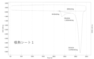
- 2 is a DSC curve of heat-absorbing sheet 1 obtained in Production Example 1.
- FIG. 2 is a DSC curve of heat-absorbing sheet 2 obtained in Production Example 2.
- FIG. 3 is a DSC curve of heat-absorbing sheet 3 obtained in Production Example 3.
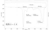
- FIG. 4 is a DSC curve of the heat-absorbing sheet 4 obtained in Production Example 4.
- FIG. 4 is a DSC curve of heat-absorbing sheet 5 obtained in Production Example 5.
- FIG. 4 is a chart showing temperature changes obtained in the endothermic property 2 test. 4 is a chart showing temperature changes obtained in a test of endothermic property 3.
- the present invention is a secondary battery module in which a heat absorbing sheet containing a heat absorbing agent is sandwiched between battery cells.
- the configuration of the present invention suppresses heat generation during high-speed charging and high-power discharging, and a rapid temperature rise of the secondary battery due to internal short circuits, etc., minimizes damage such as ignition and smoke due to thermal runaway, and By absorbing and extinguishing the heat of the high-temperature battery cells, it is possible to prevent or delay continuous explosions in other battery cells. In addition, the expansion of the battery cells themselves due to heat generation and temperature rise can be suppressed.
- the heat absorbing sheet constituting the secondary battery module of the present invention will be described below.
- the heat-absorbing sheet has a layer containing a heat-absorbing agent and a resin as a matrix.
- the heat-absorbing sheet may be a single-layer sheet having only a layer containing a heat-absorbing agent and a resin. Moreover, it may be a laminate further comprising an adhesive layer, a flame-shielding layer, or any other layer, which will be described later.
- a single-layer sheet consisting of only a layer containing a heat-absorbing agent and a resin will be referred to as a "heat-absorbing sheet" unless otherwise specified.
- the endothermic agent examples include inorganic hydrates, metal hydroxides, carbonates, and the like, which preferably have an endothermic peak at a temperature of 80°C or higher.
- the endothermic agent include inorganic hydrates, metal hydroxides, carbonates, and the like, which preferably have an endothermic peak at a temperature of 80°C or higher.
- at least one selected from the group consisting of calcium sulfate dihydrate, sodium hydrogen carbonate, aluminum hydroxide, magnesium hydroxide and calcium carbonate is preferable, and more than calcium sulfate dihydrate, sodium hydrogen carbonate and aluminum hydroxide.
- At least one selected from the group consisting of is more preferable.
- calcium sulfate dihydrate (gypsum) and sodium bicarbonate (sodium bicarbonate) are used as the endothermic agent when the temperature of the battery cell or the like rises in a short period of time (for example, to 800°C in a few seconds).
- Calcium sulfate dihydrate (gypsum) is more preferable because it can exert a heat absorption effect at a level that can more effectively prevent ignition and damage due to thermal runaway of the secondary battery. In addition to the above effect, it is particularly preferable to maintain good water resistance.
- One type of endothermic agent may be used alone, or two or more types may be used in combination.
- the endothermic starting temperature of the endothermic agent is preferably in the range of 60°C to 750°C, more preferably in the range of 80°C to 450°C, even more preferably in the range of 80°C to 300°C.
- the endothermic peak temperature of the endothermic agent is preferably in the range of 80°C to 800°C, more preferably in the range of 100°C to 500°C, even more preferably in the range of 100°C to 350°C.
- the endothermic amount of the endothermic agent is preferably in the range of 100 J/g to 1200 J/g, more preferably in the range of 300 J/g to 1200 J/g.
- the endothermic start temperature, endothermic peak temperature, and endothermic amount of each endothermic agent are values obtained by the method described later in Examples using a differential scanning calorimeter (DSC).
- the heat-absorbing sheet may contain one kind of heat-absorbing agent alone, or may contain two or more kinds of heat-absorbing agents.
- two or more endothermic agents When two or more endothermic agents are contained, it is preferable to combine two or more endothermic agents having different endothermic start temperatures or different endothermic peak temperatures.
- an endothermic agent endothermic agent 1 having a relatively low endothermic start temperature or endothermic peak temperature and an endothermic agent (endothermic agent 2) having a relatively high endothermic start temperature or endothermic peak temperature
- the temperature rises In the process of heating, an endothermic reaction is continuously generated, and thermal runaway can be effectively suppressed.
- the electrolyte In secondary batteries, for example, the electrolyte often burns, and the electrolyte burns when ignited or ignited.
- an endothermic agent having, more effective fire extinguishing is possible.
- the endothermic starting temperatures of the endothermic agent 1 and the endothermic agent 2 preferably differ by 50° C. or more, more preferably by 100° C. or more.
- the endothermic peak temperatures of the endothermic agent 1 and the endothermic agent 2 preferably differ by 50°C or more, more preferably by 100°C or more.
- the content mass ratio of each endothermic agent is not particularly limited, and the mass ratio of endothermic agent 1/endothermic agent 2 is 10/ A range of 90 to 90/10 can be set appropriately.
- the particle size of the endothermic agent is preferably in the range of 1 ⁇ m to 100 ⁇ m, more preferably in the range of 1 ⁇ m to 80 ⁇ m.
- the particle diameter of the endothermic agent is the value of the median diameter (D50) measured with a laser diffraction/scattering particle size distribution analyzer.
- thermoplastic resins examples include polyolefin resins such as polypropylene resin, polyethylene resin, poly(1-butene) resin, polyisobutylene resin and polypentene resin; polyester resins such as polyethylene terephthalate; polystyrene resins and acrylonitrile-butadiene-styrene (ABS).
- ABS acrylonitrile-butadiene-styrene
- thermosetting resins include synthetic resins such as epoxy resins, urethane resins, phenol resins, urea resins, melamine resins, unsaturated polyester resins, and polyimides.
- Elastomer resins include acrylonitrile-butadiene rubber, ethylene-propylene-diene rubber (EPDM), ethylene-propylene rubber, natural rubber, polybutadiene rubber, polyisoprene rubber, polystyrene-polybutadiene diblock copolymer or hydrogenated products thereof, polystyrene- Polybutadiene-polystyrene triblock copolymer or hydrogenated products thereof, polystyrene-polyisoprene diblock copolymer or hydrogenated products thereof, polystyrene-polyisoprene-polystyrene triblock copolymers or hydrogenated products thereof, and the like.
- thermoplastic resins are preferable among the above.
- an emulsion resin that can form voids by mechanical foaming is preferable from the viewpoint that the layer containing the heat-absorbing agent and the resin can easily form a structure having voids, and the porosity can be easily secured.
- emulsion resins include acrylic emulsion resins, urethane emulsion resins, ethylene-vinyl acetate emulsion resins, vinyl chloride emulsion resins, and epoxy emulsion resins. Among them, acrylic emulsion resins are preferable because they are excellent in heat resistance and heat insulation.
- acrylic resins include resins obtained by polymerizing monomer components containing (meth)acrylic acid alkyl esters.
- (meth)acryl is a generic term for acryl, methacryl, and both of them.
- (Meth)acrylate is a generic term for acrylate, methacrylate and both.
- (meth)acrylic acid alkyl esters include methyl (meth)acrylate, ethyl (meth)acrylate, n-propyl (meth)acrylate, isopropyl (meth)acrylate, n-butyl (meth)acrylate, and isobutyl (meth)acrylate.
- t-butyl (meth)acrylate pentyl (meth)acrylate, hexyl (meth)acrylate, heptyl (meth)acrylate, 2-ethylhexyl (meth)acrylate, n-octyl (meth)acrylate, isooctyl (meth)acrylate, nonyl (meth)acrylate, decyl (meth)acrylate, undecyl (meth)acrylate, dodecyl (meth)acrylate, tridecyl (meth)acrylate, tetradecyl (meth)acrylate and the like. These may be used individually by 1 type, or may use 2 or more types together.
- a polar group-containing monomer may be included in addition to the (meth)acrylic acid alkyl ester described above.
- polar group-containing monomers include carboxylic acids having an ethylenically unsaturated group such as (meth)acrylic acid and itaconic acid; 2-hydroxyethyl (meth)acrylate, 2-hydroxypropyl (meth)acrylate, 4-hydroxybutyl (Meth)acrylates having hydroxyl groups such as (meth)acrylates, caprolactone-modified (meth)acrylates, polyoxyethylene (meth)acrylates, polyoxypropylene (meth)acrylates; (meth)acrylonitrile, N-vinylpyrrolidone, N-vinyl Caprolactam, N-vinyllauryllactam, (meth)acryloylmorpholine, (meth)acrylamide, dimethyl (meth)acrylamide, N-methylol (meth)acryl
- the acrylic resin polymethyl (meth)acrylate and polyethyl (meth)acrylate are preferred, polymethyl (meth)acrylate is more preferred, and polymethyl methacrylate (PMMA) is even more preferred.
- the weight-average molecular weight of the acrylic resin is preferably 1,000 to 100,000, more preferably 5,000 to 90,000, and further preferably 20,000 to 80,000, from the viewpoint of facilitating dispersion of the heat-absorbing agent in the heat-absorbing sheet and improving the mechanical strength of the heat-absorbing sheet. preferable.
- the weight average molecular weight is the weight average molecular weight in terms of standard polystyrene measured by gel permeation chromatography (GPC).
- the average particle size of the emulsion resin is preferably 30 nm to 1,500 nm, more preferably 50 to 1,000 nm, from the viewpoint of facilitating the coating of the heat-absorbing agent and the resin-coated heat-absorbing agent. .
- the average particle diameter of the emulsion resin is 50% median diameter measured by a dynamic light scattering method, for example, 50% by volume measured by a Microtrac UPA type particle size distribution analyzer manufactured by Nikkiso Co., Ltd. The median diameter can be taken as the average particle diameter.
- the heat-absorbing sheet preferably has a structure in which the heat-absorbing agent is dispersed in the resin as a matrix. Moreover, the heat absorbing sheet preferably has a structure having a void. In this case, the specific gravity of the heat absorbing sheet is preferably 0.15 to 1.6, more preferably 0.2 to 1.0.
- the heat-absorbing sheet constituting the secondary battery module of the present invention is a heat-absorbing sheet having voids, the effect of temperature between battery cells can be suppressed by heat insulation, and the cushioning property (flexibility) prevents the expansion of the battery cells. It acts as a cushioning material for volume change, and tends to alleviate the internal pressure rise of the secondary battery module. Furthermore, the weight of the heat-absorbing sheet can be easily reduced, and workability is also improved.
- the content of the heat-absorbing agent in the heat-absorbing sheet is in the range of 10% by mass to 95% by mass with respect to the total components of the layer containing the heat-absorbing agent and the resin as the matrix, from the viewpoint of easily realizing suitable heat absorption. preferably in the range of 50% by mass to 90% by mass, and even more preferably in the range of 65% by mass to 90% by mass.
- the content of the resin in the heat-absorbing sheet is preferably in the range of 5 to 90% by mass, more preferably 10 to 50% by mass, from the viewpoint of facilitating the adjustment of the content of the voids and the heat-absorbing agent and the improvement of both contents. is more preferred, and a range of 10 to 35% by mass is even more preferred.
- the amount ratio of the heat absorbing agent and the resin is preferably 80/20 to 15/85 in terms of the solid content mass ratio represented by the heat absorbing agent/resin. It is preferably 70/30 to 30/70, more preferably.
- the heat absorbing sheet may further contain a heat storage material.
- the endothermic agent described above is a substance that decomposes by absorbing heat.
- the heat storage material is positioned as a substance that absorbs heat when the phase changes from solid to liquid, and releases heat when the phase changes from liquid to solid. If a heat storage material with a relatively high temperature (that is, melting point) that causes a phase change is selected, the heat generated during charging of the secondary battery can be absorbed by the heat storage material, thereby suppressing a rapid temperature rise of the secondary battery. It is possible to prevent deterioration and ignition of the secondary battery.
- a heat storage material that causes a phase change at a relatively low temperature when the temperature of the secondary battery drops as the ambient temperature drops, the heat stored in the heat storage material is released, can prevent the temperature from dropping.
- the melting point of the heat storage material is preferably 15° C. to 60° C., more preferably 20° C. to 50° C., from the viewpoint of suppressing a rapid temperature rise of the secondary battery and better absorbing heat generated during charging. is more preferred, and 30°C to 45°C is even more preferred.
- the heat storage material is not particularly limited, but examples thereof include fatty acid esters and alkanes (paraffins). These compounds may be used individually by 1 type, or may use 2 or more types together.
- fatty acid esters include methyl myristate, methyl palmitate, ethyl palmitate, methyl stearate, and ethyl stearate. Among them, preferred are methyl palmitate, ethyl palmitate, methyl stearate and ethyl stearate, and more preferred is methyl stearate.
- alkanes examples include hexadecane, heptadecane, octadecane, nonadecane, icosane, henicosane, and docosane.
- heptadecane, octadecane, nonadecane, icosane, henicosane and docosane are preferred, nonadecane, icosane, henicosane and docosane are more preferred, and icosane, henicosane and docosane are even more preferred.
- Such a heat storage material is preferably in the form of coated particles coated with a shell made of an organic material such as melamine resin, acrylic resin, or urethane resin.
- the average particle size of the coated particles is not particularly limited, but is preferably 10 ⁇ m to 3000 ⁇ m. By using the coated particles having an average particle diameter within this range, it becomes easy to form voids between the coated particles and to achieve good moldability in the heat-absorbing sheet.
- the average particle size is more preferably 30 ⁇ m or more, still more preferably 50 ⁇ m or more, and particularly preferably 100 ⁇ m or more.
- the average particle size is more preferably 2,000 ⁇ m or less, and even more preferably 1,000 ⁇ m or less.
- the average particle diameter of the primary particles is within the above range.
- the average particle diameter of the coated particles is measured by a laser diffraction particle size distribution analyzer (manufactured by Horiba, Ltd., "LA-950V2"), and the obtained median diameter (the particle diameter corresponding to 50% of the volume cumulative distribution : 50% particle size).
- thermomemory FP-16, FP-25, FP-31, FP-39 (all trade names) manufactured by Mitsubishi Paper Mills, and Riken Resin PMCD-15SP manufactured by Miki Riken Kogyo Co., Ltd., as those having an outer shell made of melamine resin.
- 25SP, 32SP all trade names
- Riken resins LA-15, LA-25, LA-32 (all trade names) manufactured by Miki Riken Kogyo Co., Ltd., etc. as those having an outer shell made of silica
- Polymethyl methacrylate Micronal DS5001X, 5040X both trade names) manufactured by BASF, etc. as those having an outer shell made of resin
- NJ2721 both are trade names
- the heat absorbing sheet may further contain other additives as necessary.
- Other additives include, for example, flame retardants, harmful substance adsorbents such as formaldehyde, deodorants, color pigments, and the like.
- flame retardant organic flame retardants and inorganic flame retardants can be used as appropriate.
- organic flame retardant include phosphorus compounds, halogen compounds, and guanidine compounds, and specific examples include primary ammonium phosphate, secondary ammonium phosphate, triester phosphate, phosphite, and phosphonium.
- inorganic flame retardants include antimony and aluminum compounds, boron compounds, and ammonium compounds. ammonium sulfate, ammonium sulfamate and the like. A flame retardant may be used individually by 1 type, or may use 2 or more types together.
- a heat-absorbing sheet can be produced by preparing a composition containing a heat-absorbing agent and a resin and molding the composition.
- the composition can be molded by applying a diluted solution obtained by diluting the composition with a solvent on a release sheet and drying, and the resin composition may be molded by extrusion molding, press molding, injection molding, or the like.
- the resin composition contains a relatively large amount of heat-absorbing agent (for example, when the content of the heat-absorbing agent is 50% by mass or more based on the total amount of the resin composition), a heat-absorbing sheet having good dispersibility of the heat-absorbing agent is used.
- the solvent used for diluting the resin composition is not particularly limited, and examples include aliphatic or aromatic hydrocarbons such as pentane, hexane, cyclohexane, and toluene; esters such as ethyl acetate and n-butyl acetate; acetone, methyl ethyl ketone, and the like. ketones; alcohols such as ethanol, isopropanol, butanol, ethyl carbitol, ethyl cellosolve and butyl cellosolve; water and the like.
- a diluted solution of the resin composition is usually in the form of a slurry in which the resin is dissolved in a solvent and the heat-absorbing agent is dispersed in the solvent.
- a solvent and an endothermic agent are stirred with a dispersing mixer such as a bead mill to prepare a dispersion, then a resin solution dissolved in advance in a solvent is added to the dispersion, and the resin is further stirred with the dispersing mixer. Dilutions of the composition can be made.
- the content of the heat-absorbing agent in the resin composition may be blended so that the ratio of heat-absorbing agent/resin in the heat-absorbing sheet is within the above range.
- the diluent of the resin composition may be a mixture of the endothermic agent and the emulsion resin described above.
- Solvents that constitute such emulsion resins are preferably water or aqueous media that are mixtures of water and water-soluble solvents.
- water-soluble solvents include alcohols such as methanol, ethanol, isopropanol, ethyl carbitol, ethyl cellosolve and butyl cellosolve, and polar solvents such as N-methylpyrrolidone.
- the solid content concentration in the resin composition diluted with a solvent is, for example, 30 to 70% by mass, preferably 35 to 65% by mass, and more preferably 40 to 60% by mass.
- the content of the resin in the resin composition is preferably 30 to 200 parts by mass, more preferably 50 to 150 parts by mass, relative to 100 parts by mass of the aqueous medium when an acrylic emulsion resin is used, for example. is more preferred. In this case, it becomes easy to adjust the viscosity of the resin composition to a suitable range, and to stably foam the resin composition.
- the heat-absorbing sheet having voids which the secondary battery module of the present invention has as a preferred embodiment, can be produced by a method including mechanical foaming or chemical foaming.
- the heat-absorbing sheet having voids can preferably be produced by mechanically foaming a resin composition containing a heat-absorbing agent and the emulsion resin described above, followed by coating or casting, followed by drying.
- the resin composition may be dried and then cured by heat, ultraviolet rays, or the like, if necessary.
- the resin composition further containing a thermal decomposition type foaming agent and a foaming aid is supplied to an extruder, melt-kneaded, and extruded into a sheet to obtain a sheet
- a method of foaming a thermally decomposable foaming agent in the sheet can be mentioned.
- the thermal decomposition type foaming agent includes azodicarbonamide, N,N'-dinitrosopentamethylenetetramine, p-toluenesulfonyl semicarbazide, etc., and may be used alone or in combination of two or more. .
- the amount of the thermally decomposable foaming agent added is usually preferably 1 part by mass to 40 parts by mass with respect to 100 parts by mass of the resin, from the viewpoint of easily adjusting the foaming ratio, tensile strength, compression recovery rate, etc. within the desired range. , more preferably 1 to 30 parts by mass.
- the method for foaming the thermally decomposable foaming agent in the sheet is not particularly limited, and examples thereof include a method of heating with hot air, infrared rays, a salt bath, or an oil bath.
- the resin composition may optionally be mixed with a surfactant, a thickener, a flame retardant, a cross-linking agent, and the like.
- a surfactant can be mixed in the resin composition for the purpose of miniaturizing and stabilizing foamed foam. Any of anionic surfactants, cationic surfactants, nonionic surfactants, amphoteric surfactants and the like may be used as surfactants.
- the surfactant is preferably an anionic surfactant, and more preferably a fatty acid ammonium surfactant such as ammonium stearate.
- Surfactant may be used individually by 1 type, or may use 2 or more types together.
- the content thereof is preferably 30 parts by mass or less relative to 100 parts by mass (solid content) of the resin, since it facilitates obtaining suitable foaming properties. 5 to 20 parts by mass is more preferable, and 3 to 15 parts by mass is even more preferable.
- a thickening agent can be mixed in order to improve the stability and film-forming properties of the foamed foam.
- thickeners include acrylic acid-based thickeners, urethane-based thickeners, polyvinyl alcohol-based thickeners, and the like. Among them, acrylic acid-based thickeners and urethane-based thickeners are preferred.
- the content is preferably 0.1 to 10 parts by mass, and 0.5 to 8 parts by mass with respect to 100 parts by mass (solid content) of the resin. more preferred.
- a curing agent may be mixed with the resin composition.
- the curing agent can be appropriately selected according to the type of resin used, and examples thereof include epoxy curing agents, melamine curing agents, isocyanate curing agents, carbodiimide curing agents, oxazoline curing agents and the like.
- the thickness of the heat absorbing sheet is preferably 100 ⁇ m to 20000 ⁇ m, more preferably 100 ⁇ m to 6000 ⁇ m, even more preferably 100 ⁇ m to 3000 ⁇ m, and even more preferably 100 ⁇ m to 1000 ⁇ m. In this case, it is possible to further improve handling properties such as cushioning properties, mechanical strength, and workability of the foamed sheet.
- the heat-absorbing sheet preferably has a mandrel diameter of 25 mm or less, more preferably 20 mm or less, and 16 mm or less at which cracks occur in a bending resistance test according to JIS K5600-5-1 (1999). is more preferred.
- a heat-absorbing sheet that satisfies these requirements can ensure suitable flexibility and excellent conformability to the surfaces of various members.
- the bending resistance of the heat-absorbing sheet measured according to the Gurley method defined in JIS L1913 (2010) is preferably 0.1 to 30 mN, more preferably 0.5 to 20 mN, More preferably, it is 1 to 10 mN.
- a heat-absorbing sheet having such a bending resistance can also ensure suitable flexibility and excellent conformability to the surfaces of various members.
- the tensile strength of the heat absorbing sheet is preferably 0.1 MPa or more, more preferably 0.2 MPa or more.
- the heat-absorbing sheet can be made tough while having flexibility.
- such a heat absorbing sheet is less likely to be cracked during processing, transportation, and the like, and can exhibit suitable workability, handleability, transportation suitability, bending suitability, and the like, which is preferable.
- the upper limit of the tensile strength of the heat-absorbing sheet is not particularly limited, it is preferably 15 MPa or less, more preferably 10 MPa or less, and even more preferably 5 MPa or less.
- the elongation at breakage of the heat-absorbing sheet is preferably 5% or more, more preferably 30% or more, and even more preferably 50% or more. In this case, embrittlement of the heat absorbing sheet 20 can be suppressed. Moreover, even if such a heat absorbing sheet is bent or distorted during processing, transportation, or the like, cracking or chipping is unlikely to occur.
- the upper limit of the elongation at breakage of the heat-absorbing sheet is preferably 1000% or less, more preferably 500% or less, and even more preferably 300% or less. In this case, the heat-absorbing sheet can realize excellent flexibility while being tough. Therefore, the heat-absorbing sheet is easy to obtain good workability, handleability, transportability, conformability to the surfaces of various members, and the like.
- the tensile strength and elongation at breakage of the heat absorbing sheet can be measured according to the method specified in JIS K6251. Specifically, the heat-absorbing sheet is cut into a No. 2 dumbbell shape to prepare a test piece with two marked lines with an initial distance between marked lines of 20 mm. This test piece is attached to a tensile tester and pulled at a speed of 200 mm/min to break. At this time, the maximum force (N) until breakage and the distance between gauge lines (mm) at breakage are measured, and the tensile strength and the elongation at breakage can be calculated from the following equations.
- the tensile strength T S (MPa) is calculated by the following formula.
- TS Fm /Wt
- Fm is the maximum force (N)
- W is the width of the parallel portion (mm)
- t is the thickness of the parallel portion (mm).
- E b (L b ⁇ L 0 )/L 0 ⁇ 100
- Lb is the distance between the marked lines (mm) at breakage
- L0 is the initial distance between the marked lines (mm).
- Adhesive layer From the viewpoint of further improving the adhesion between each battery cell in the secondary battery module of the present invention, for example, as shown in FIG. good. That is, in the secondary battery module of the present invention, a plurality of battery cells may be fixed by the adhesive layer further included in the heat absorbing sheet.
- adhesives capable of forming an adhesive layer include those containing resins such as natural rubber, synthetic rubber, acrylic resins, silicone resins, urethane resins, and vinyl ether resins as binders.
- the form of the pressure-sensitive adhesive may be any of solvent-based, emulsion-based, water-based, hot-melt-type, and non-solvent-based, such as active energy ray-curable type such as ultraviolet rays and electron beams.
- the respective adhesive layers may have the same adhesive strength or different adhesive strengths.
- one of the adhesive layers may be a so-called strong adhesive layer and the other may be a weak adhesive layer.
- each adhesive layer may have the same composition or different compositions.
- the adhesive strength of the adhesive layer can also be designed in consideration of disassembly of the secondary battery module.
- the pressure-sensitive adhesive that can form the pressure-sensitive adhesive layer preferably contains a solvent from the viewpoint of maintaining good coating workability. Examples of the solvent that can be used include toluene, xylene, ethyl acetate, butyl acetate, acetone, methyl ethyl ketone, and hexane.
- the aqueous solvent which consists mainly of water or water can be used.
- the pressure-sensitive adhesive capable of forming the pressure-sensitive adhesive layer may contain a tackifying resin, a cross-linking agent, other additives, etc., if necessary.
- tackifying resins include rosin, polymerized rosin, polymerized rosin ester, rosin phenol, stabilized rosin ester, disproportionated rosin ester, terpene, terpene phenol fat, petroleum resin, and the like.
- tackifying resins include rosin, polymerized rosin, polymerized rosin ester, rosin phenol, stabilized rosin ester, disproportionated rosin ester, terpene, terpene phenol fat, petroleum resin, and the like.
- Various tackifying resins can be mentioned.
- cross-linking agents examples include known cross-linking agents such as isocyanate-based, epoxy-based, aziridine-based, polyvalent metal salt-based, metal chelate-based, keto-hydrazide-based, oxazoline-based, carbodiimide-based, silane-based, and glycidyl (alkoxy)epoxysilane-based agents. agents, which can be used for the purpose of improving the cohesive strength of the pressure-sensitive adhesive layer (B).
- Other additives include known foaming agents, plasticizers, softeners, antioxidants, fillers such as glass and plastic fibers, balloons, beads, and metal powders, colorants such as pigments and dyes, and pH adjusters. agents, film forming aids, leveling agents, thickeners, water repellents, antifoaming agents and the like. These other additives can be added within a range that does not impair the desired effects of the present invention.
- the thickness of the adhesive layer is preferably 10 ⁇ m or less, more preferably in the range of 1 ⁇ m to 5 ⁇ m.
- the adhesive layer may contain the endothermic agent described above.
- the heat-absorbing sheet may be a laminate having a flame-shielding layer. If the heat-absorbing sheet has a flame-shielding layer, even if the secondary battery ignites due to rapid heat generation or temperature rise, the flame is blocked, which is effective in preventing or delaying the spread of fire to other battery cells.
- the heat absorbing sheet further has both the adhesive layer and the flame shielding layer, the flame shielding layer is provided inside the adhesive layer.
- the flame-shielding layer woven fabrics, non-woven fabrics, inorganic fiber sheets made of inorganic fibers, non-combustible paper, and the like can be suitably used.
- the flame-shielding layer can be provided, for example, by laminating an inorganic fiber sheet on one surface of the heat-absorbing sheet, as shown in FIG.
- the inorganic fiber sheet that can be applied to the flame barrier layer include glass cloth made of glass wool, rock wool, glass fiber, or the like.
- An inorganic fiber sheet may be used independently or may be used in combination of 2 or more types.
- Specific examples of non-combustible paper that can be applied to the flame barrier layer include paper coated with, impregnated with, or internally added with a flame retardant to impart self-extinguishing properties and suppress the spread of flames.
- the flame retardant include metal oxides such as magnesium hydroxide and aluminum hydroxide, basic compounds such as phosphates, borates and stefamates, and glass fibers.
- the thickness of the flame barrier layer is not particularly limited, and can be set as appropriate within a range of, for example, 10 to 1000 ⁇ m. Further, the weight per unit area of the inorganic fiber sheet as the flame barrier layer is preferably 1 to 1000 mg/cm 2 .
- Thermal conduction layer As the heat absorbing sheet, a sheet having a heat conductive layer on one side or both sides thereof is used, so that even when the temperature of the battery cell or the like rises (for example, when it reaches 800 ° C.), the heat conductivity is The heat is transferred in the plane direction by the high thermal conductivity layer, and the heat absorption agent efficiently absorbs the heat, so that the temperature rise on the surface can be suppressed more effectively. It is preferable because it can more effectively prevent ignition and damage due to runaway. Furthermore, when the heat conductive layer is a metal foil such as an aluminum foil, the effect of reflecting radiant heat can be obtained, and the transfer of heat generated by thermal runaway can be further delayed.
- the heat conductive layer for example, it is preferable to use a metal foil (metal layer) such as aluminum foil, copper foil, iron foil, or a graphite sheet. Even when the temperature of the secondary battery rises, the surface temperature rise can be more effectively suppressed, and as a result, ignition and damage due to thermal runaway of the secondary battery can be more effectively prevented. Moreover, when a metal layer is used as the heat conductive layer, deformation of the heat-absorbing sheet can be suppressed and flame-shielding properties can be imparted, which is particularly preferable. Moreover, as the heat conductive layer, a layer in which a plurality of materials are laminated can also be used.
- a laminate of the metal layer and a fiber material (fiber sheet) capable of imparting adhesion to the metal layer More specifically, it is preferable to use a laminate of an aluminum foil and a paper material as the heat conductive layer in order to improve the adhesion between the heat conductive layer and the heat absorbing sheet.
- a method of laminating the aluminum foil and the paper material for example, a method of laminating them with a polyethylene sheet or the like can be mentioned.
- the heat conductive layer preferably has a thickness of 5 ⁇ m to 200 ⁇ m, and using a layer of 5 ⁇ m to 50 ⁇ m achieves both the above effect and thinning and weight reduction of the secondary battery module. preferable.
- the lower limit of the thermal conductivity of the thermal conductive layer is preferably 0.045 W/m ⁇ K or more, more preferably 1 W/m ⁇ K or more.
- the upper limit of the thermal conductivity of the thermally conductive layer is preferably 1800 W/m ⁇ K or less, more preferably 500 W/m ⁇ K or less.
- the heat-absorbing sheet is a laminate further comprising, in addition to a layer containing a heat-absorbing agent and a resin as a matrix, an adhesive layer, a flame-shielding layer, a heat-conducting layer, an adhesive layer, or any other layer,
- a laminate further comprising, in addition to a layer containing a heat-absorbing agent and a resin as a matrix, an adhesive layer, a flame-shielding layer, a heat-conducting layer, an adhesive layer, or any other layer.
- It can be produced through a step of foaming by applying and heating a resin containing.
- Such a laminate can also be produced by directly applying the above-described adhesive to both surfaces of the heat-absorbing sheet and drying to form an adhesive layer.
- adhesives capable of forming the adhesive layer include urethane resin adhesives, acrylic resin adhesives, polyester resin adhesives, and the like.
- the heat-absorbing sheet contains a heat-absorbing agent typified by the calcium sulfate dihydrate (gypsum) and sodium hydrogen carbonate (sodium bicarbonate), has voids, and A heat-absorbing sheet having a heat-conducting layer typified by aluminum foil can be mentioned. Ignition or breakage of secondary batteries may be caused by thermal runaway (that is, a state in which temperature control of battery cells that form the secondary batteries is not possible). The risk of thermal runaway increases when the temperature of the battery cell exceeds about 80°C. It becomes difficult to suppress the runaway.
- thermal runaway that is, a state in which temperature control of battery cells that form the secondary batteries is not possible.
- the heat absorbing sheet should: (1) absorb heat before the temperature of the battery cell reaches 160°C to stop thermal runaway; and (2) the heat of a battery cell that has reached a high temperature is transferred to other adjacent battery cells, thereby suppressing the occurrence of thermal runaway in a plurality of battery cells.
- the heat-absorbing sheet containing a heat-absorbing agent typified by calcium sulfate dihydrate (gypsum) and sodium hydrogen carbonate (sodium bicarbonate) can be used when the temperature of the battery cell, etc. Even in the case where the thermal runaway of the secondary battery is reached), the effects shown in (1) and (2) can be obtained, and as a result, ignition and damage due to thermal runaway of the secondary battery can be more effectively suppressed.
- a heat absorbing sheet having a heat conductive layer such as aluminum foil can exhibit the effects shown in (1) and (2) above, and as a result, ignition and damage due to thermal runaway of the secondary battery can be prevented. can be suppressed more effectively.
- the heat absorbing sheet having the voids (porous) can suppress the temperature influence between the battery cells by heat insulating properties, and also acts as a cushioning material for the volume change due to the expansion of the battery cells due to the cushioning properties (flexibility). An increase in internal pressure of the secondary battery module can be mitigated.
- the heat-absorbing sheet contains a heat-absorbing agent typified by the calcium sulfate dihydrate (gypsum) and sodium hydrogen carbonate (sodium bicarbonate), and has a metal layer typified by the aluminum foil. , an endothermic sheet having no voids. Its thickness is preferably 100 ⁇ m to 10000 ⁇ m, more preferably 100 ⁇ m to 3000 ⁇ m.
- the type of the secondary battery is not particularly limited. Examples include silver-zinc oxide batteries, metal-air batteries, polyvalent cation batteries, capacitors, capacitors, and the like. Among them, lithium-ion batteries can be mentioned as suitable applications.
- a secondary battery module of the present invention is, for example, a secondary battery that is mounted on a vehicle or the like, and has a plurality of battery cells and a case that houses the plurality of battery cells.
- a battery cell constituting a secondary battery module uses, for example, a battery exterior film as an exterior material, and a battery element including at least a positive electrode material, a negative electrode material, a separator, a positive electrode terminal, a negative electrode terminal, etc. is enclosed in the exterior material. can be any battery cell.
- the exterior material is usually formed by heat-sealing the sealant layers of the battery exterior film, and has a flange portion (region where the sealant layers are heat-sealed together) on the periphery.
- a positive electrode terminal and a negative electrode terminal connected to the positive electrode material and the negative electrode material respectively protrude from the flange portion to the outside.
- the heat absorbing sheet is sandwiched between adjacent battery cells housed in a case.
- the case can be made of, for example, aluminum, iron, or a metal material containing these, or a resin material such as polyphenylene sulfide. Forming the case from a resin material can contribute to weight reduction of the secondary battery module.
- the heat-absorbing sheet can be sandwiched between the battery cells by, for example, an adhesive, fusion (ultrasonic fusion, high-frequency fusion, heat fusion), adhesive, or the like.
- an adhesive fusion (ultrasonic fusion, high-frequency fusion, heat fusion), adhesive, or the like.
- the heat absorbing sheet is a laminate further having an adhesive layer, it is possible to omit the additional use of an adhesive or a pressure-sensitive adhesive, which is advantageous from the viewpoint of workability in module production.
- the resulting foamable mixture was applied onto a polyethylene terephthalate (PET) film with an applicator.
- PET polyethylene terephthalate
- the coated material is pre-dried by heating at 105°C for 5 minutes and then at 120°C for 3 minutes.
- the sheet is turned over and further heat-treated at 120°C for 3 minutes for curing. to produce a heat absorbing sheet 1 having a thickness of 1 mm.
- the specific gravity of the heat absorbing sheet 1 was 0.64, the mass was 640 g/m 2 , and the mass of the heat absorbing agent in the heat absorbing sheet 1 was 514 g/m 2 .
- a cross section obtained by cutting the heat absorbing sheet 1 was confirmed with an electron microscope (Digital Microscope VHX-900 manufactured by Keyence Corporation).
- Heat-absorbing sheets 2 to 5 were produced in the same manner as in Production Example 1 except that the resin 1, foam stabilizer 1, cross-linking agent 1, and heat-absorbing agent were used in the same manner as shown in Table 1.
- a plastisol coating solution was prepared by mixing 100 parts by mass of resin 2 (vinyl chloride resin paste) and 120 parts by mass of aluminum hydroxide as an endothermic agent, and this plastisol coating solution was applied onto a PET film using an applicator. . The coated material was pre-dried by heating at 100° C. for 5 minutes, followed by heat treatment at 140° C. for 10 minutes for curing, and the PET film was removed to produce a heat absorbing sheet 6 having a thickness of 1 mm.
- a heat-absorbing sheet 7 was produced in the same manner as in Production Example 6, except that the heat-absorbing agent and heat storage agent 1 were blended as shown in Table 1.
- a sheet 1 was produced in the same manner as in Production Example 1, except that the endothermic agent was not blended.
- a sheet 2 was produced in the same manner as in Production Example 6, except that no endothermic agent was blended.
- a sheet 3 was produced in the same manner as in Production Example 6, except that the types and blending amounts of the resin 2 and the endothermic agent were as shown in Table 1.
- a sheet 4 was produced in the same manner as in Production Example 6, except that the heat storage agent 1 as shown in Table 1 was blended without blending the heat absorbing agent.
- a heat-absorbing sheet 8 was obtained in the same manner as in Production Example 1, except that a glass cloth (140 ⁇ m thick) was used instead of the PET film, and the step of removing the PET film and the glass cloth was not performed. rice field.
- a polyolefin foam sheet material (Toraypef product number 300050 AG00, thermal conductivity 0.035 W/m ⁇ K_ manufactured by TORAY) was prepared as the heat insulating material 1 .
- Example 1 A secondary battery module was produced by sandwiching the heat absorbing sheet 1 obtained in Production Example 1 between battery cells.
- Examples 2 to 9, Comparative Examples 1 to 4 A secondary battery module was fabricated in the same manner as in Example 1 using the heat absorbing sheets 2 to 9, sheets 1 to 4, and heat insulating materials 1 to 2 obtained in Production Example.
- Endothermic property 1 The endothermic start temperature and the endothermic peak temperature of the endothermic sheet were measured as follows. Using a differential scanning calorimeter (DSC; DSC-7020, manufactured by Hitachi High-Tech Co., Ltd.), the temperature was raised from 0 ° C. to 350 ° C. at 1 ° C./min in a nitrogen atmosphere, and the baseline of the DSC measurement curve at this time melted. The endothermic onset temperature (°C) was defined as the temperature at which the peak started to rise, and the endothermic peak temperature (°C) was defined as the maximum difference from the baseline of the DSC measurement curve.
- DSC differential scanning calorimeter
- the endothermic value (J/g) was obtained by dividing the integrated value of the endothermic peak based on the baseline of the DSC measurement curve by the mass of the endothermic agent used for the measurement.
- the DSC curves of each sheet are also shown in FIGS.
- the exothermic heater was caused to generate heat with a constant amount of heat of 30 W, and the time required for the temperature T between the heat absorbing sheet and the wood in contact with it to reach 160°C was measured. evaluated.
- the temperature T was taken as a measurement point corresponding to the surface temperature of a cell placed next to the heat-generating cell via a heat-absorbing sheet or the like.
- the result of evaluation without using the heat absorbing sheet in the above test was used as a reference example.
- thermocouple is attached to the bottom surface of the heat absorbing sheet or sheet prepared in Example 2, Example 3 and Comparative Example 6, the side and bottom surfaces are wrapped with aluminum foil, placed in a holding frame, and the back surface side is filled with inorganic fibers. and then pushed into the specimen holder.
- the specimen holder was placed on the cone calorimeter, and radiant heat of 50 kW/m 2 was applied to the surface of the specimen from a radiant heat electric heater.
- the temperature of the radiant heat electric heater was actually measured, it was 800.degree. C. to 850.degree.
- the temperature of the surface opposite to the heating side of the heat-absorbing sheets, heat insulating materials, and sheets prepared in the above Examples and Comparative Examples was measured, and the time until the temperature reached 160 ° C. was measured. evaluated.
- the secondary battery module of the present invention can suppress a rapid temperature rise of the secondary battery due to heat generated during high-speed charging or high-power discharging, and can prevent ignition and damage due to thermal runaway, thus improving the safety of the secondary battery.
- a battery it is useful for various purposes.
Landscapes
- Chemical & Material Sciences (AREA)
- Chemical Kinetics & Catalysis (AREA)
- Electrochemistry (AREA)
- General Chemical & Material Sciences (AREA)
- Engineering & Computer Science (AREA)
- Manufacturing & Machinery (AREA)
- Power Engineering (AREA)
- Microelectronics & Electronic Packaging (AREA)
- Inorganic Chemistry (AREA)
- Secondary Cells (AREA)
- Electric Double-Layer Capacitors Or The Like (AREA)
- Battery Mounting, Suspending (AREA)
Priority Applications (4)
| Application Number | Priority Date | Filing Date | Title |
|---|---|---|---|
| US18/730,521 US20250132413A1 (en) | 2022-02-04 | 2022-09-15 | Secondary battery module |
| CN202280083867.0A CN118435428A (zh) | 2022-02-04 | 2022-09-15 | 二次电池模块 |
| JP2023563850A JP7529168B2 (ja) | 2022-02-04 | 2022-09-15 | 二次電池モジュール |
| KR1020247020045A KR20240146653A (ko) | 2022-02-04 | 2022-09-15 | 이차 전지 모듈 |
Applications Claiming Priority (2)
| Application Number | Priority Date | Filing Date | Title |
|---|---|---|---|
| JP2022016441 | 2022-02-04 | ||
| JP2022-016441 | 2022-02-04 |
Publications (1)
| Publication Number | Publication Date |
|---|---|
| WO2023149009A1 true WO2023149009A1 (ja) | 2023-08-10 |
Family
ID=87553287
Family Applications (1)
| Application Number | Title | Priority Date | Filing Date |
|---|---|---|---|
| PCT/JP2022/034507 Ceased WO2023149009A1 (ja) | 2022-02-04 | 2022-09-15 | 二次電池モジュール |
Country Status (5)
| Country | Link |
|---|---|
| US (1) | US20250132413A1 (https=) |
| JP (1) | JP7529168B2 (https=) |
| KR (1) | KR20240146653A (https=) |
| CN (1) | CN118435428A (https=) |
| WO (1) | WO2023149009A1 (https=) |
Cited By (4)
| Publication number | Priority date | Publication date | Assignee | Title |
|---|---|---|---|---|
| KR102691409B1 (ko) * | 2023-08-16 | 2024-08-05 | 주식회사 엘지화학 | 흡열 패드 |
| WO2025234618A1 (ko) * | 2024-05-10 | 2025-11-13 | 주식회사 엘지에너지솔루션 | 열적 배리어 패드, 배터리 팩, 및 배터리 모듈 |
| WO2026005551A1 (ko) * | 2024-06-28 | 2026-01-02 | 주식회사 엘지화학 | 다층 흡열 패드 |
| WO2026010102A1 (ko) * | 2024-07-05 | 2026-01-08 | 주식회사 세스맷 | 이차전지용 자가 발포 폼 복합 패드 및 그 제조 방법 |
Citations (2)
| Publication number | Priority date | Publication date | Assignee | Title |
|---|---|---|---|---|
| JP2018206605A (ja) * | 2017-06-05 | 2018-12-27 | 積水化学工業株式会社 | 熱暴走防止シート |
| JP2020532078A (ja) * | 2017-08-29 | 2020-11-05 | カール・フロイデンベルク・カーゲーCarl Freudenberg KG | エネルギ貯蔵システム |
Family Cites Families (5)
| Publication number | Priority date | Publication date | Assignee | Title |
|---|---|---|---|---|
| JPS5828925Y2 (ja) | 1979-09-12 | 1983-06-24 | 三菱自動車工業株式会社 | 自動車用視認装置 |
| KR20130115989A (ko) | 2010-06-07 | 2013-10-22 | 블루핀 로보틱스 코포레이션 | 배터리 셀과 배터리 셀을 포함하는 배터리의 보호 방법 및 보호된 배터리 셀과 배터리 셀을 포함하는 배터리 |
| JP2020119841A (ja) * | 2019-01-25 | 2020-08-06 | イビデン株式会社 | 熱伝達抑制部材及びその使用方法 |
| JP2021002425A (ja) | 2019-06-19 | 2021-01-07 | 積水化学工業株式会社 | 電池用外装フィルム、及び電池 |
| JP7404704B2 (ja) * | 2019-08-09 | 2023-12-26 | Toppanホールディングス株式会社 | 不燃シートの製造方法及び不燃シート |
-
2022
- 2022-09-15 CN CN202280083867.0A patent/CN118435428A/zh active Pending
- 2022-09-15 US US18/730,521 patent/US20250132413A1/en active Pending
- 2022-09-15 KR KR1020247020045A patent/KR20240146653A/ko active Pending
- 2022-09-15 WO PCT/JP2022/034507 patent/WO2023149009A1/ja not_active Ceased
- 2022-09-15 JP JP2023563850A patent/JP7529168B2/ja active Active
Patent Citations (2)
| Publication number | Priority date | Publication date | Assignee | Title |
|---|---|---|---|---|
| JP2018206605A (ja) * | 2017-06-05 | 2018-12-27 | 積水化学工業株式会社 | 熱暴走防止シート |
| JP2020532078A (ja) * | 2017-08-29 | 2020-11-05 | カール・フロイデンベルク・カーゲーCarl Freudenberg KG | エネルギ貯蔵システム |
Cited By (4)
| Publication number | Priority date | Publication date | Assignee | Title |
|---|---|---|---|---|
| KR102691409B1 (ko) * | 2023-08-16 | 2024-08-05 | 주식회사 엘지화학 | 흡열 패드 |
| WO2025234618A1 (ko) * | 2024-05-10 | 2025-11-13 | 주식회사 엘지에너지솔루션 | 열적 배리어 패드, 배터리 팩, 및 배터리 모듈 |
| WO2026005551A1 (ko) * | 2024-06-28 | 2026-01-02 | 주식회사 엘지화학 | 다층 흡열 패드 |
| WO2026010102A1 (ko) * | 2024-07-05 | 2026-01-08 | 주식회사 세스맷 | 이차전지용 자가 발포 폼 복합 패드 및 그 제조 방법 |
Also Published As
| Publication number | Publication date |
|---|---|
| US20250132413A1 (en) | 2025-04-24 |
| KR20240146653A (ko) | 2024-10-08 |
| JP7529168B2 (ja) | 2024-08-06 |
| JPWO2023149009A1 (https=) | 2023-08-10 |
| CN118435428A (zh) | 2024-08-02 |
Similar Documents
| Publication | Publication Date | Title |
|---|---|---|
| JP6700490B2 (ja) | 耐火積層体及びバッテリー | |
| JP7529168B2 (ja) | 二次電池モジュール | |
| JP6764023B2 (ja) | 耐火樹脂組成物、耐火シート、耐火積層体、及びバッテリー | |
| JP7601268B2 (ja) | 二次電池 | |
| WO2021100813A1 (ja) | バッテリーパック用熱膨張性耐火材、バッテリーパック用耐火シート、及び車載用バッテリーパック | |
| DE102021119483A1 (de) | Mehrschichtige brandschutzschicht- und batteriepack, die dieselbe umfasst | |
| JP2020136100A (ja) | 耐火シート及びバッテリー | |
| JP2022119610A (ja) | 発火抑制シート及び電子機器 | |
| JP2020041121A (ja) | 耐火樹脂組成物、耐火シート、耐火積層体、及びバッテリー | |
| WO2020241843A1 (ja) | バッテリー用熱膨張性耐火材 | |
| JP7150643B2 (ja) | 耐火積層体及びバッテリー | |
| KR20210096723A (ko) | 난연성 복합 패드, 그 제조 방법, 이러한 복합 패드를 포함하는 이차전지 모듈과 이차전지 팩 | |
| JP2021080382A (ja) | 筐体用熱膨張性耐火材、筐体用耐火シート、及び携帯電子機器用筐体 | |
| JP2021002426A (ja) | 電池用外装フィルム、及び電池 | |
| JP2021163712A (ja) | バッテリーセル構造及び電子機器 | |
| CN117222451A (zh) | 灭火用层叠体、灭火用层叠体的制造方法以及电子部件 | |
| JP2020161249A (ja) | バッテリーセル及びバッテリー | |
| JP2022125931A (ja) | スラリー分散液及び耐火材 | |
| JP2022119663A (ja) | 積層体、耐火シート及びバッテリー | |
| KR102907324B1 (ko) | 소화 성능이 우수한 고분자 폼 필름 및 이를 적용한 리튬 이차전지 | |
| KR102947310B1 (ko) | 리튬이온전지용 열폭주 방지 및 지연 특성을 구비한 3단계 조성물 및 그 제조 방법 | |
| JP2020147734A (ja) | 耐火樹脂組成物、耐火シート、及びバッテリー | |
| JP2022047440A (ja) | 耐火シート及びバッテリー | |
| JP2025036375A (ja) | 樹脂組成物、ペレット及び成形体 | |
| KR20250156876A (ko) | 내화 성능이 향상된 다공성 폼 단열시트 및 이를 적용한 제품 |
Legal Events
| Date | Code | Title | Description |
|---|---|---|---|
| 121 | Ep: the epo has been informed by wipo that ep was designated in this application |
Ref document number: 22924914 Country of ref document: EP Kind code of ref document: A1 |
|
| WWE | Wipo information: entry into national phase |
Ref document number: 2023563850 Country of ref document: JP |
|
| WWE | Wipo information: entry into national phase |
Ref document number: 202280083867.0 Country of ref document: CN |
|
| WWE | Wipo information: entry into national phase |
Ref document number: 18730521 Country of ref document: US |
|
| NENP | Non-entry into the national phase |
Ref country code: DE |
|
| 122 | Ep: pct application non-entry in european phase |
Ref document number: 22924914 Country of ref document: EP Kind code of ref document: A1 |
|
| WWP | Wipo information: published in national office |
Ref document number: 18730521 Country of ref document: US |