WO2023145396A1 - Dispositif de diffusion thermique et appareil électronique - Google Patents
Dispositif de diffusion thermique et appareil électronique Download PDFInfo
- Publication number
- WO2023145396A1 WO2023145396A1 PCT/JP2023/000092 JP2023000092W WO2023145396A1 WO 2023145396 A1 WO2023145396 A1 WO 2023145396A1 JP 2023000092 W JP2023000092 W JP 2023000092W WO 2023145396 A1 WO2023145396 A1 WO 2023145396A1
- Authority
- WO
- WIPO (PCT)
- Prior art keywords
- wall surface
- convex portion
- support
- wick
- diffusion device
- Prior art date
Links
Images


Classifications
-
- F—MECHANICAL ENGINEERING; LIGHTING; HEATING; WEAPONS; BLASTING
- F28—HEAT EXCHANGE IN GENERAL
- F28D—HEAT-EXCHANGE APPARATUS, NOT PROVIDED FOR IN ANOTHER SUBCLASS, IN WHICH THE HEAT-EXCHANGE MEDIA DO NOT COME INTO DIRECT CONTACT
- F28D15/00—Heat-exchange apparatus with the intermediate heat-transfer medium in closed tubes passing into or through the conduit walls ; Heat-exchange apparatus employing intermediate heat-transfer medium or bodies
- F28D15/02—Heat-exchange apparatus with the intermediate heat-transfer medium in closed tubes passing into or through the conduit walls ; Heat-exchange apparatus employing intermediate heat-transfer medium or bodies in which the medium condenses and evaporates, e.g. heat pipes
- F28D15/04—Heat-exchange apparatus with the intermediate heat-transfer medium in closed tubes passing into or through the conduit walls ; Heat-exchange apparatus employing intermediate heat-transfer medium or bodies in which the medium condenses and evaporates, e.g. heat pipes with tubes having a capillary structure
-
- H—ELECTRICITY
- H01—ELECTRIC ELEMENTS
- H01L—SEMICONDUCTOR DEVICES NOT COVERED BY CLASS H10
- H01L23/00—Details of semiconductor or other solid state devices
- H01L23/34—Arrangements for cooling, heating, ventilating or temperature compensation ; Temperature sensing arrangements
- H01L23/42—Fillings or auxiliary members in containers or encapsulations selected or arranged to facilitate heating or cooling
- H01L23/427—Cooling by change of state, e.g. use of heat pipes
-
- H—ELECTRICITY
- H05—ELECTRIC TECHNIQUES NOT OTHERWISE PROVIDED FOR
- H05K—PRINTED CIRCUITS; CASINGS OR CONSTRUCTIONAL DETAILS OF ELECTRIC APPARATUS; MANUFACTURE OF ASSEMBLAGES OF ELECTRICAL COMPONENTS
- H05K7/00—Constructional details common to different types of electric apparatus
- H05K7/20—Modifications to facilitate cooling, ventilating, or heating
Definitions
- the present invention relates to heat diffusion devices and electronic equipment.
- a vapor chamber has a structure in which a working medium (also called a working fluid) and a wick that transports the working medium by capillary force are sealed inside a housing.
- the working medium absorbs heat from the heat-generating elements such as electronic parts in the evaporator, evaporates in the vapor chamber, moves in the vapor chamber, is cooled, and returns to the liquid phase. .
- the working medium that has returned to the liquid phase moves again to the evaporating portion on the heating element side by the capillary force of the wick, and cools the heating element.
- the vapor chamber can operate independently without external power, and heat can be two-dimensionally diffused at high speed by utilizing the latent heat of vaporization and latent heat of condensation of the working medium.
- Patent Document 1 discloses a thermal ground plane, which is an example of a vapor chamber.
- the thermal ground plane described in Patent Document 1 includes a first planar substrate member, a plurality of micropillars arranged on the first planar substrate, and at least some of the micropillars a vapor core disposed on at least one of said first planar substrate, said micropillars and said mesh; and disposed on said first planar substrate. wherein the mesh separates the micropillars from the vapor core, the first planar substrate and the second planar substrate are connected to the micropillars; Surrounding the mesh and the steam core.
- a wick is composed of struts such as micropillars and perforated bodies such as mesh.
- a perforated body of the vapor chamber a perforated body obtained by forming holes in a metal plate by etching or the like is used.
- the surface of the perforated body and the surface surrounded by the peripheries of the perforations are flush with each other in the portion in contact with the vapor layer.
- the flow of vapor in the vapor layer greatly affects the working medium in the holes.
- the wick is easily affected by the flow of vapor in the direction opposite to the capillary force, the so-called counterflow, so the counterflow reduces the capillary force of the wick. As a result, there is a problem that the maximum heat transfer amount of the vapor chamber is lowered.
- the present invention has been made to solve the above problems, and an object of the present invention is to provide a heat diffusion device capable of improving the maximum amount of heat transport. A further object of the present invention is to provide an electronic device comprising the above heat diffusion device.
- a heat diffusion device of the present invention comprises a housing having a first inner wall surface and a second inner wall surface facing each other in a thickness direction, a working medium enclosed in an internal space of the housing, and the internal space of the housing.
- the wick includes a support in contact with the first inner wall surface and a perforated body in contact with the support, the perforated body penetrating in the thickness direction A through hole is provided, and a protrusion is provided on the periphery of the through hole in a direction approaching the second inner wall surface.
- the electronic device of the present invention includes the heat diffusion device of the present invention.
- thermoelectric device capable of improving the maximum amount of heat transport. Furthermore, according to the present invention, it is possible to provide an electronic device comprising the above heat diffusion device.
- FIG. 1 is a perspective view schematically showing an example of the heat diffusion device of the present invention.
- FIG. 2 is an example of a cross-sectional view along line II-II of the heat spreading device shown in FIG. 3A is a partially enlarged cross-sectional view schematically showing an example of a wick constituting the heat diffusion device shown in FIG. 2.
- FIG. 3B is a perspective view schematically showing the shape of the convex portion of the wick shown in FIG. 3A.
- FIG. 3C is a perspective view schematically showing another example of the shape of the convex portion of the wick shown in FIG. 3A.
- FIG. FIG. 4A is an example of a plan view of the wick shown in FIG. 3A viewed from the support side.
- FIG. 4B is another example of a plan view of the wick shown in FIG. 3A viewed from the support side.
- FIG. 5 is a plan view schematically showing the flow of vapor in the through-holes, the projections, and the vicinity of the projections when the wick shown in FIG. 3A is viewed from the perforated body side.
- FIG. 6A is a partially enlarged cross-sectional view schematically showing a first modified example of the convex portion.
- FIG. 6B is a perspective view schematically showing the shape of the convex portion shown in FIG. 6A.
- FIG. 7A is a partially enlarged cross-sectional view schematically showing a second modification of the convex portion.
- FIG. 7B is a perspective view schematically showing the shape of the convex portion shown in FIG.
- FIG. 8-1A is a partially enlarged cross-sectional view schematically showing a third modified example of the projection.
- FIG. 8-1B is a perspective view schematically showing the shape of the projection shown in FIG. 8-1A.
- FIG. 8-2A is a partially enlarged sectional view schematically showing another example of the projection shown in FIG. 8-1A.
- FIG. 8-2B is a perspective view schematically showing the shape of the projection shown in FIG. 8-2A.
- FIG. 8-3A is a partially enlarged sectional view schematically showing another example of the projection shown in FIG. 8-1A.
- FIG. 8-3B is a perspective view schematically showing the shape of the projection shown in FIG. 8-3A.
- FIG. 9 is a partially enlarged cross-sectional view schematically showing a fourth modified example of the projection.
- FIG. 10 is a partially enlarged cross-sectional view schematically showing a fifth modification of the convex portion.
- FIG. 11 is a partially enlarged sectional view schematically showing a first modification of the wick.
- FIG. 12 is a partially enlarged cross-sectional view schematically showing a first modification of the convex portion in the wick shown in FIG. 11 .
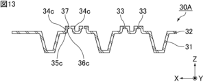
- FIG. 13 is a partially enlarged cross-sectional view schematically showing a second modification of the convex portion in the wick shown in FIG. 11 .
- FIG. 14 is a partially enlarged sectional view schematically showing a second modification of the wick.
- FIG. 15 is a plan view schematically showing a third modification of the wick.
- FIG. 16 is a cross-sectional view schematically showing a first modification of the heat diffusion device.
- FIG. 17 is a cross-sectional view schematically showing a second modification of the heat diffusion device.
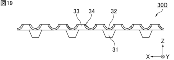
- FIG. 18 is a plan view of the first modification of the wick shown in FIG. 3A, viewed from the perforated body side.
- FIG. 19 is a cross-sectional view of the wick shown in FIG. 18 along line AA.
- FIG. 20 is a diagram for explaining the definition of convex portions in the wick shown in FIG.
- FIG. 21 is a diagram for explaining the definition of convex portions in the wick shown in FIG. 19.
- FIG. 20 is a diagram for explaining the definition of convex portions in the wick shown in FIG.
- the heat diffusion device of the present invention will be described below.
- the present invention is not limited to the following embodiments, and can be appropriately modified and applied without changing the gist of the present invention.
- a combination of two or more of the individual preferred configurations of the present invention described below is also the present invention.
- a vapor chamber will be described below as an example of an embodiment of the heat diffusion device of the present invention.
- the heat diffusion device of the present invention can also be applied to heat diffusion devices such as heat pipes.
- FIG. 1 is a perspective view schematically showing an example of the heat diffusion device of the present invention.
- FIG. 2 is an example of a cross-sectional view along line II-II of the heat spreading device shown in FIG.
- a vapor chamber (heat diffusion device) 1 shown in FIGS. 1 and 2 includes a hollow casing 10 that is hermetically sealed.
- the housing 10 has a first inner wall surface 11a and a second inner wall surface 12a facing each other in the thickness direction Z.
- the vapor chamber 1 further includes a working medium 20 enclosed in the inner space of the housing 10 and a wick 30 arranged in the inner space of the housing 10 .
- An evaporator that evaporates the enclosed working medium 20 is set in the housing 10 .
- a heat source HS which is a heating element, is arranged on the outer wall surface of the housing 10 .
- the heat source HS include electronic components of electronic equipment, such as a central processing unit (CPU).
- CPU central processing unit
- a portion of the internal space of the housing 10 that is in the vicinity of the heat source HS and is heated by the heat source HS corresponds to the evaporator.
- the vapor chamber 1 is preferably planar as a whole. That is, the housing 10 as a whole is preferably planar.
- the “planar shape” includes a plate shape and a sheet shape, and the dimension in the width direction X (hereinafter referred to as width) and the dimension in the length direction Y (hereinafter referred to as length) are the thickness direction Z Shapes that are considerably large relative to their dimensions (hereinafter referred to as thickness or height), such as shapes whose width and length are 10 times or more, preferably 100 times or more, their thickness.
- the size of the vapor chamber 1, that is, the size of the housing 10 is not particularly limited.
- the width and length of the vapor chamber 1 can be appropriately set according to the application.
- the width and length of the vapor chamber 1 are, for example, 5 mm or more and 500 mm or less, 20 mm or more and 300 mm or less, or 50 mm or more and 200 mm or less.
- the width and length of the vapor chamber 1 may be the same or different.
- the housing 10 is preferably composed of a first sheet 11 and a second sheet 12 that face each other and whose outer edges are joined.
- the material of which the first sheet 11 and the second sheet 12 are composed should have properties suitable for use as a vapor chamber, such as thermal conductivity, strength, and the like. , flexibility, flexibility, etc., and is not particularly limited.
- the material that constitutes the first sheet 11 and the second sheet 12 is preferably a metal, such as copper, nickel, aluminum, magnesium, titanium, iron, or an alloy containing them as a main component, and copper is particularly preferable. is.
- the materials forming the first sheet 11 and the second sheet 12 may be the same or different, but are preferably the same.
- the housing 10 is composed of the first sheet 11 and the second sheet 12
- the first sheet 11 and the second sheet 12 are joined together at their outer edge portions.
- the method of such bonding is not particularly limited, but for example, laser welding, resistance welding, diffusion bonding, brazing, TIG welding (tungsten-inert gas welding), ultrasonic bonding or resin sealing can be used, which is preferable. can use laser welding, resistance welding or brazing.
- the thicknesses of the first sheet 11 and the second sheet 12 are not particularly limited, but each is preferably 10 ⁇ m or more and 200 ⁇ m or less, more preferably 30 ⁇ m or more and 100 ⁇ m or less, still more preferably 40 ⁇ m or more and 60 ⁇ m or less.
- the thicknesses of the first sheet 11 and the second sheet 12 may be the same or different. Also, the thickness of each sheet of the first sheet 11 and the second sheet 12 may be the same over the entire area, or may be thin in part.
- first sheet 11 and the second sheet 12 are not particularly limited.
- first sheet 11 and the second sheet 12 may each have a shape in which the outer edges are thicker than the portions other than the outer edges.
- the thickness of the entire vapor chamber 1 is not particularly limited, it is preferably 50 ⁇ m or more and 500 ⁇ m or less.
- the planar shape of the housing 10 when viewed from the thickness direction Z is not particularly limited, and examples thereof include polygonal shapes such as triangles and rectangles, circular shapes, elliptical shapes, and shapes combining these shapes. Further, the planar shape of the housing 10 may be L-shaped, C-shaped (U-shaped), step-shaped, or the like. Moreover, the housing 10 may have a through hole. The planar shape of the housing 10 may be a shape according to the use of the vapor chamber, the shape of the location where the vapor chamber is installed, and other parts existing nearby.
- the working medium 20 is not particularly limited as long as it can cause a gas-liquid phase change in the environment inside the housing 10.
- water, alcohols, CFC alternatives, etc. can be used.
- working medium 20 is an aqueous compound, preferably water.
- the wick 30 has a capillary structure that can move the working medium 20 by capillary force.
- the size and shape of the wick 30 are not particularly limited, it is preferable that the wicks 30 are arranged continuously in the internal space of the housing 10, for example.
- the wick 30 may be arranged in the entire internal space of the housing 10 when viewed from the thickness direction Z, or the wick 30 may be arranged in a part of the internal space of the housing 10 when viewed from the thickness direction Z. may be
- FIG. 3A is a partially enlarged cross-sectional view schematically showing an example of a wick that constitutes the heat diffusion device shown in FIG.
- the wick 30 includes a support 31 in contact with the first inner wall surface 11a and a perforated body 32 in contact with the support 31. As shown in FIGS. 2 and 3A, the wick 30 includes a support 31 in contact with the first inner wall surface 11a and a perforated body 32 in contact with the support 31. As shown in FIGS.
- the perforated body 32 is composed of the same material as the support 31.
- the material constituting the support 31 and the perforated body 32 is not particularly limited. Examples include laminates.
- a metal is preferable for the material constituting the support 31 and the perforated body 32 .
- the support 31 and the perforated body 32 may be constructed integrally.
- “the support 31 and the perforated body 32 are integrated” means that there is no interface between the support 31 and the perforated body 32. Specifically, , means that the boundary between the support 31 and the perforated body 32 cannot be distinguished.
- the wick 30 in which the support 31 and the perforated body 32 are integrally formed can be produced, for example, by etching technology, printing technology using multi-layer coating, or other multi-layer technology.
- the support 31 and the perforated body 32 may not be integrally formed.
- the entire surface between the support 31 and the perforated body 32 is Since it is difficult to join over the entire surface, a gap is generated in a part between the support 31 and the perforated body 32 .
- the support 31 and the perforated body 32 are not integrally constructed, but the perforated body 32 It can be said that it is made of the same material as the support 31 .
- FIG. 4A is an example of a plan view of the wick shown in FIG. 3A viewed from the support side.
- FIG. 4B is another example of a plan view of the wick shown in FIG. 3A viewed from the support side.
- the support 31 includes, for example, multiple columnar members.
- columnar means a shape in which the ratio of the length of the long side of the bottom surface is less than five times the length of the short side of the bottom surface.
- the shape of the columnar member is not particularly limited, examples thereof include a cylindrical shape, a prismatic shape, a truncated cone shape, and a truncated pyramid shape.
- the cross-sectional shape of the support 31 perpendicular to the height direction is rectangular, and in the example shown in FIG. 4B, the cross-sectional shape of the support 31 perpendicular to the height direction is circular.
- the columnar member should be relatively taller than its surroundings. Therefore, the columnar member includes, in addition to the portion protruding from the first inner wall surface 11a, a portion relatively high due to the depression formed in the first inner wall surface 11a.
- the shape of the support 31 is not particularly limited, but as shown in FIGS. 2 and 3A, the support 31 preferably has a tapered shape in which the width narrows from the perforated body 32 toward the first inner wall surface 11a. .
- the support 31 preferably has a tapered shape in which the width narrows from the perforated body 32 toward the first inner wall surface 11a.
- the arrangement of the supports 31 is not particularly limited, they are preferably arranged evenly in a predetermined area, more preferably evenly over the entire area, for example, so that the center-to-center distance (pitch) of the supports 31 is constant.
- the center-to-center distance of the support 31 (the length indicated by P31 in FIG. 4A or 4B) is, for example, 60 ⁇ m or more and 800 ⁇ m or less.
- the width of the support 31 (the length indicated by W31 in FIG. 4A or 4B) is, for example, 20 ⁇ m or more and 500 ⁇ m or less.
- the height of the support 31 (the length indicated by T31 in FIG. 3A) is, for example, 10 ⁇ m or more and 100 ⁇ m or less.
- the perforated body 32 has a through hole 33 penetrating in the thickness direction Z. Within the through hole 33, the working medium 20 can move by capillary action.
- the through hole 33 is preferably provided in a portion where the support 31 does not exist when viewed from the thickness direction Z. As shown in FIG. Although the shape of the through hole 33 is not particularly limited, it is preferable that the cross section of the plane perpendicular to the thickness direction Z is circular or elliptical.
- the arrangement of the through holes 33 of the perforated body 32 is not particularly limited. are arranged so that is constant.
- the center-to-center distance (the length indicated by P33 in FIG. 4A or 4B) of the through holes 33 of the perforated body 32 is, for example, 3 ⁇ m or more and 150 ⁇ m or less.
- the diameter of the end surface of the through-hole 33 on the side of the second inner wall surface 12a is, for example, 100 ⁇ m or less.
- the thickness of the perforated body 32 (the length indicated by T32 in FIG. 3A) is, for example, 5 ⁇ m or more and 50 ⁇ m or less.
- the thickness of the perforated body 32 means the thickness of the perforated body 32 at a portion where the later-described projections 34 are not provided.
- a protruding portion 34 is provided on the periphery of the through hole 33 so as to approach the second inner wall surface 12a.
- FIG. 3B is a perspective view schematically showing the shape of the convex portion of the wick shown in FIG. 3A.
- the convex portion 34 has a first end 35 on the side of the first inner wall surface 11a and a second end 36 on the side of the second inner wall surface 12a.
- the convex portion 34 has a cylindrical shape.
- the shape of the convex portion 34 is, for example, a cylindrical shape with a flat second end portion 36 .
- the shape of the convex portion 34 may be a square tube shape, or a hollow shape such as a truncated cone or a truncated pyramid.
- FIG. 5 is a plan view schematically showing the flow of steam in the vicinity of the through-holes, the projections, and the projections when the wick shown in FIG. 3A is viewed from the perforated body side.
- the working medium 20 evaporated in the heat source HS flows in a vapor state through the space between the perforated body 32 and the second inner wall surface 12a in a direction away from the heat source HS.
- a convex portion 34 is provided on the periphery of the through-hole 33 in a direction approaching the second inner wall surface 12a, the space between the perforated body 32 and the second inner wall surface 12a is reduced.
- the flowing steam flows so as to bypass the outer peripheral edges of the projections 34 . Therefore, it is possible to prevent the steam flow from directly contacting the liquid surface of the working medium 20 in the through hole 33 . Therefore, it is possible to reduce the effect of vapor flow in the direction opposite to the capillary force of the wick 30, that is, the so-called counterflow. Therefore, the maximum heat transfer amount of the vapor chamber 1 can be improved.
- the convex portion 34 is provided along the entire periphery of the through hole 33 .
- the convex portion 34 may be provided only on a part of the periphery of the through hole 33 .
- the protrusions 34 may be provided around all the through holes 33 in the perforated body 32 , or only around some of the through holes 33 in the perforated body 32 . When the protrusions 34 are provided only along the periphery of some of the through holes 33 in the perforated body 32, the protrusions 34 may be provided along the periphery of the perforations other than the through holes 33 positioned directly above the heat source HS. preferable.
- the through holes 33 and the projections 34 can be produced, for example, by punching the metal or the like that constitutes the perforated body 32 by press working.
- punching by press working the formation of the projections, the shape of the projections, and the like can be adjusted by appropriately adjusting the punching depth and the like.
- the punching depth means, for example, how far the punch is pushed in the punching direction when punching with a punch.
- the dimensions of the convex portion 34 are not particularly limited.
- the height of the protrusion 34 may be greater than the diameter of the through hole 33, or the height of the protrusion 34 may be smaller than the diameter of the through hole 33, and the height of the protrusion 34 may be It may be the same as the diameter of the through hole 33 .
- the height of the protrusion 34 means the distance in the thickness direction Z between the first end 35 and the second end 36. As shown in FIG.
- FIG. 3C is a perspective view schematically showing another example of the shape of the convex portion of the wick shown in FIG. 3A.
- the second end portion 36 is uneven, not flat.
- the height of the projection 34 is the maximum of the distances in the thickness direction Z between the first end 35 and the second end 36. means distance.
- FIG. 6A is a partially enlarged cross-sectional view schematically showing a first modified example of the convex portion.
- FIG. 6B is a perspective view schematically showing the shape of the convex portion shown in FIG. 6A.
- the projection 34a shown in FIGS. 6A and 6B has a first end 35a on the side of the first inner wall surface 11a and a second end 36a on the side of the second inner wall surface 12a.
- the cross-sectional area of the region surrounded by the inner wall of the second end portion 36a is smaller than the cross-sectional area of the region surrounded by the inner wall of the first end portion 35a.
- the cross-sectional area of the region surrounded by the inner wall of the second end portion 36 a when viewed from the thickness direction Z is smaller than the cross-sectional area of the region surrounded by the inner wall of the first end portion 35 a , the flow of steam is restricted in the through hole 33 . Direct contact with the liquid surface of the working medium 20 can be further prevented. As a result, the influence of the counterflow can be further reduced, so that the maximum heat transfer amount of the vapor chamber 1 can be further improved.
- the inner wall of the second end portion 36a is located inside the inner wall of the first end portion 35a when viewed from the thickness direction Z.
- the steam flow directly contacts the liquid surface of the working medium 20 in the through hole 33. can be further prevented.
- the influence of the counterflow can be further reduced, so that the maximum heat transfer amount of the vapor chamber 1 can be further improved.
- the convex portion 34a has a tapered shape in a cross section along the thickness direction Z such that the distance between the outer walls of the convex portion 34a becomes narrower toward the second inner wall surface 12a.
- the protrusion 34a has a tapered shape in which the distance between the outer walls of the protrusion 34a becomes narrower toward the second inner wall surface 12a, the perforated body 32 and the second inner wall surface 12a are tapered.
- the distance between the outer walls of the convex portion 34a becomes narrower toward the second inner wall surface 12a, compared to the convex portion 34 that does not have a tapered shape. It is possible to increase the flow path of the steam in contact with 34a. As a result, a decrease in thermal conductivity of the vapor chamber 1 can be suppressed.
- the convex portion 34a has a shape convex toward the second inner wall surface 12a side (upward in FIG. 6A) in a cross section along the thickness direction Z. In other words, the convex portion 34a curves toward the second inner wall surface 12a (upward in FIG. 6A) with respect to a line segment connecting the first end portion 35a and the second end portion 36a in a cross section along the thickness direction Z. Shape.
- FIG. 7A is a partially enlarged cross-sectional view schematically showing a second modification of the convex portion.
- FIG. 7B is a perspective view schematically showing the shape of the convex portion shown in FIG. 7A.
- the convex portion 34b shown in FIGS. 7A and 7B has a first end 35b on the side of the first inner wall surface 11a and a second end 36b on the side of the second inner wall surface 12a.
- the convex portion 34b has a tapered shape in a cross section along the thickness direction Z such that the distance between the outer walls of the convex portion 34b becomes narrower toward the second inner wall surface 12a.
- the convex portion 34b has a shape convex toward the first inner wall surface 11a side (lower side in FIG. 7A) in a cross section along the thickness direction Z. As shown in FIG. In other words, the convex portion 34b curves toward the first inner wall surface 11a (downward in FIG.
- FIG. 8-1A is a partially enlarged cross-sectional view schematically showing a third modified example of the convex portion.
- FIG. 8-1B is a perspective view schematically showing the shape of the projection shown in FIG. 8-1A.
- the projection 34c shown in FIGS. 8-1A and 8-1B has a first end 35c on the side of the first inner wall surface 11a and a second end 36c on the side of the second inner wall surface 12a.
- the cross-sectional area of the region surrounded by the inner wall of the second end portion 36c is smaller than the cross-sectional area of the region surrounded by the inner wall of the first end portion 35c.
- the convex portion 34c has a lid portion 37 that narrows the opening of the convex portion 34c at the second end portion 36c.
- the convex portion 34c when viewed from the thickness direction Z, the cross-sectional area of the region surrounded by the inner wall of the second end portion 36c is narrower than the convex portion 34b in which the lid portion 37 does not exist at the second end portion 36c.
- the convex portion 34c is provided with a lid portion 37 that narrows the opening of the convex portion 34c at the second end portion 36c, the flow of steam is further prevented from directly contacting the liquid surface of the working medium 20 in the through hole 33. can be done. As a result, the influence of the counterflow can be further reduced, so that the maximum heat transfer amount of the vapor chamber 1 can be further improved.
- the lid portion 37 that narrows the opening of the convex portion 34c may be formed, for example, by pressing the second end portion 36c.
- the size and shape of the lid portion 37 that narrows the opening of the convex portion 34c are not particularly limited as long as the opening on the second end portion 36c side of the convex portion 34c is narrowed.
- the lid portion 37 that narrows the opening of the convex portion 34c preferably has a flat surface.
- the lid portion 37 that narrows the opening of the convex portion 34c is preferably a flat surface perpendicular to the thickness direction Z. As shown in FIG. A part or the whole of the lid portion 37 that narrows the opening of the convex portion 34c may be curved.
- the lid portion 37 that narrows the opening of the convex portion 34c may have an uneven surface.
- the thickness of the lid portion 37 that narrows the opening of the convex portion 34c may be the same as or different from the thickness of the convex portion 34c.
- the lid portion 37 is provided over the entire second end portion 36c. 8-1A and 8-1B, the center of the peripheral edge of the through-hole 33 at the first end 35c and the center of the peripheral edge of the through-hole 33 at the second end 36c are aligned.
- FIG. 8-2A is a partially enlarged sectional view schematically showing another example of the convex portion shown in FIG. 8-1A.
- FIG. 8-2B is a perspective view schematically showing the shape of the projection shown in FIG. 8-2A.
- the lid portion 37 is provided only on part of the second end portion 36c.
- the lid portion 37 is provided only on the right side of the convex portion 34c, and the lid portion 37 is not provided on the left side of the convex portion 34c.
- the center of the peripheral edge of the through-hole 33 at the first end 35c and the center of the peripheral edge of the through-hole 33 at the second end 36c do not match.
- FIG. 8-3A is a partially enlarged sectional view schematically showing another example of the convex portion shown in FIG. 8-1A.
- FIG. 8-3B is a perspective view schematically showing the shape of the projection shown in FIG. 8-3A.
- the lid portion 37 is provided only on part of the second end portion 36c.
- the lid portion 37 is provided only on the right side of the convex portion 34c, and the lid portion 37 is not provided on the left side of the convex portion 34c.
- a lid portion 37 having a substantially circular cross section is provided on a portion of the second end portion 36c.
- the lid portion 37 is a flat surface perpendicular to the thickness direction Z, but FIGS.
- the lid portion 37 is provided so as to extend toward the second inner wall surface 12a side (the upper side in FIG. 8-3A). In FIGS. 8-3A and 8-3B, the lid portion 37 has a flat surface, but the lid portion 37 may have a curved surface.
- FIG. 9 is a partially enlarged cross-sectional view schematically showing a fourth modified example of the convex portion.
- a convex portion 34d shown in FIG. 9 has a first end 35d on the side of the first inner wall surface 11a and a second end 36d on the side of the second inner wall surface 12a.
- the cross-sectional area of the region surrounded by the inner wall of the second end portion 36d is larger than the cross-sectional area of the region surrounded by the inner wall of the first end portion 35d.
- the inner wall of the second end portion 36d is located outside the inner wall of the first end portion 35d when viewed from the thickness direction Z.
- FIG. 10 is a partially enlarged cross-sectional view schematically showing a fifth modified example of the convex portion.
- the convex portion 34e shown in FIG. 10 has a first end 35e on the side of the first inner wall surface 11a and a second end 36e on the side of the second inner wall surface 12a.
- the cross-sectional area of the region surrounded by the inner wall of the second end portion 36e is larger than the cross-sectional area of the region surrounded by the inner wall of the first end portion 35e.
- the convex portion 34e has a lid portion 37 that narrows the opening of the convex portion 34e at the second end portion 36e.
- the convex portion 34e when viewed from the thickness direction Z, the cross-sectional area of the region surrounded by the inner wall of the second end portion 36e is narrower than that of the convex portion 34d in which the lid portion 37 does not exist at the second end portion 36e.
- the convex portion 34e is provided with a lid portion 37 that narrows the opening of the convex portion 34e at the second end portion 36e, the flow of steam is further prevented from directly contacting the liquid surface of the working medium 20 in the through hole 33. can be done. As a result, the influence of the counterflow can be further reduced, so that the maximum heat transfer amount of the vapor chamber 1 can be further improved.
- the lid portion 37 that narrows the opening of the convex portion 34e may be formed, for example, by pressing the second end portion 36e.
- the size and shape of the lid portion 37 that narrows the opening of the convex portion 34e are not particularly limited as long as the opening on the second end portion 36e side of the convex portion 34e is narrowed.
- the lid portion 37 that narrows the opening of the convex portion 34e preferably has a flat surface.
- the lid portion 37 that narrows the opening of the convex portion 34e preferably has a flat surface perpendicular to the thickness direction Z. As shown in FIG. A part or the whole of the lid portion 37 that narrows the opening of the convex portion 34e may be curved.
- the lid portion 37 that narrows the opening of the convex portion 34e may have an uneven surface.
- the thickness of the lid portion 37 that narrows the opening of the convex portion 34e may be the same as or different from the thickness of the convex portion 34e.
- FIG. 11 is a partially enlarged sectional view schematically showing a first modification of the wick.
- a support 31 is formed in the recessed portion by bending and recessing a portion of the metal foil by press working or the like.
- a vapor space is formed in the recessed portion of the support 31, thereby improving thermal conductivity.
- a through hole may be formed in a recessed portion when a part of the metal foil is bent.
- the thickness of the metal foil is constant before performing press working or the like. However, the metal foil may become thin at the bent portion. From the above, in the wick 30A, it is preferable that the thickness of the support 31 is the same as the thickness of the perforated body 32 or smaller than the thickness of the perforated body 32 .
- the wick 30A is preferably formed by collectively performing press work for forming the support 31 and press work for forming the through holes 33 and the projections 34 .
- the thickness of the projections 34 may be the same as the thickness of the support 31.
- the thickness of the protrusions 34 may be the same as the thickness of the perforated body 32 .
- the thickness of the support 31, the thickness of the perforated body 32, and the thickness of the projections 34 may be constant.
- the thickness of the projections 34 may be different from the thickness of the support 31. In the wick 30A, the thickness of the projections 34 may differ from the thickness of the perforated body 32. FIG.
- FIG. 12 is a partially enlarged cross-sectional view schematically showing a first modification of the convex portion in the wick shown in FIG.
- the convex portion 34b shown in FIG. 12 has the same shape as the convex portion 34b shown in FIGS. 7A and 7B.
- the protrusion 34b has a first end 35b on the side of the first inner wall surface 11a and a second end 36b on the side of the second inner wall surface 12a.
- the convex portion 34b has a tapered shape in a cross section along the thickness direction Z such that the distance between the outer walls of the convex portion 34b becomes narrower toward the second inner wall surface 12a.
- the convex portion 34b has a shape convex toward the first inner wall surface 11a side (lower side in FIG. 12) in a cross section along the thickness direction Z. As shown in FIG.
- the convex portion 34b curves toward the first inner wall surface 11a (downward in FIG. 12) with respect to a line segment connecting the first end portion 35b and the second end portion 36b in a cross section along the thickness direction Z. It is a shape that
- the thickness of the convex portion 34b may be the same as or different from the thickness of the support 31.
- the thickness of the protrusions 34b may be the same as or different from the thickness of the perforated body 32 .
- FIG. 13 is a partially enlarged cross-sectional view schematically showing a second modification of the convex portion in the wick shown in FIG.
- the convex portion 34c shown in FIG. 13 has the same shape as the convex portion 34c shown in FIGS. 8-1A and 8-1B.
- the protrusion 34c has a first end 35c on the first inner wall surface 11a side and a second end 36c on the second inner wall surface 12a side.
- the cross-sectional area of the region surrounded by the inner wall of the second end portion 36c is smaller than the cross-sectional area of the region surrounded by the inner wall of the first end portion 35c.
- the convex portion 34c has a lid portion 37 that narrows the opening of the convex portion 34c at the second end portion 36c.
- the thickness of the convex portion 34c may be the same as or different from the thickness of the support 31.
- the thickness of the convex portion 34c may be the same as the thickness of the perforated body 32, or may be different.
- the thickness of the lid portion 37 that narrows the opening of the convex portion 34c may be the same as or different from the thickness of the support 31 .
- the thickness of the lid portion 37 that narrows the opening of the convex portion 34c may be the same as or different from the thickness of the perforated body 32 .
- the convex portion 34 shown in FIG. 11 may have the same shape as the convex portion 34a shown in FIGS. 6A and 6B, the convex portion 34d shown in FIG. 9, or the convex portion 34e shown in FIG.
- FIG. 14 is a partially enlarged sectional view schematically showing a second modification of the wick.
- the perforated body 32 is made of a different material than the support 31.
- Materials constituting the support 31 are not particularly limited, but examples thereof include resins, metals, ceramics, or mixtures and laminates thereof.
- Materials constituting the perforated body 32 are not particularly limited, but examples thereof include resins, metals, ceramics, or mixtures and laminates thereof.
- Metal is preferable as the material for forming the perforated body 32 .
- the convex portion 34 shown in FIG. 14 includes the convex portion 34a shown in FIGS. 6A and 6B, the convex portion 34b shown in FIGS. 7A and 7B, the convex portion 34c shown in FIGS. 8-1A and 8-1B, and FIG. 8-2B, the projections 34c shown in FIGS. 8-3A and 8-3B, the projections 34d shown in FIG. 9, or the projections 34e shown in FIG. .
- FIG. 15 is a plan view schematically showing a third modification of the wick. Note that FIG. 15 is a plan view of the wick viewed from the support side.
- the support 31 includes a plurality of rail-shaped members.
- rail-like means a shape in which the ratio of the length of the long side of the bottom surface is five times or more the length of the short side of the bottom surface.
- the cross-sectional shape perpendicular to the extending direction of the rail-shaped member is not particularly limited, but examples thereof include polygonal shapes such as quadrangles, semicircular shapes, semielliptical shapes, and shapes in which these are combined.
- the rail-shaped member should be relatively taller than its surroundings. Therefore, the rail-shaped member includes not only the portion protruding from the first inner wall surface 11a, but also the relatively high portion due to the grooves formed in the first inner wall surface 11a.
- the wick 30C is not limited to the shape disclosed in FIG. 15, and may be used by being partially arranged instead of being arranged in the entire internal space.
- a rail-shaped support member 31 may be formed along the outer periphery in the internal space, and a perforated member 32 having a shape along the outer periphery may be arranged thereon.
- a pillar 40 may be arranged in the internal space of the housing 10 so as to contact the second inner wall surface 12a. It is possible to support the housing 10 and the wick 30 by arranging the struts 40 in the internal space of the housing 10 .
- the material forming the pillars 40 is not particularly limited, but examples thereof include resins, metals, ceramics, mixtures thereof, laminates, and the like.
- the support 40 may be integrated with the housing 10, or may be formed by etching the second inner wall surface 12a of the housing 10, for example.
- the shape of the support 40 is not particularly limited as long as it can support the housing 10 and the wick 30, but the shape of the cross section of the support 40 perpendicular to the height direction may be, for example, a polygon such as a rectangle, a circle, or an ellipse. shape, etc.
- the height of the struts 40 may be the same or different in one vapor chamber.
- the width of the support 40 is not particularly limited as long as it provides strength capable of suppressing deformation of the housing 10. is, for example, 100 ⁇ m or more and 2000 ⁇ m or less, preferably 300 ⁇ m or more and 1000 ⁇ m or less.
- the equivalent circle diameter of the strut 40 By increasing the equivalent circle diameter of the strut 40, the deformation of the housing 10 can be further suppressed.
- the equivalent circle diameter of the strut 40 it is possible to ensure a wider space for the vapor of the working medium 20 to move.
- the arrangement of the struts 40 is not particularly limited, they are preferably arranged evenly in a predetermined area, more preferably evenly over the entire area, for example, so that the distance between the struts 40 is constant. By arranging the struts 40 evenly, it is possible to ensure uniform strength throughout the vapor chamber 1 .
- FIG. 16 is a cross-sectional view schematically showing a first modification of the heat diffusion device.
- the support 31 is integrally formed with the first sheet 11 of the housing 10.
- the first sheet 11 and the support 31 can be produced by, for example, an etching technique, a printing technique using multi-layer coating, or other multi-layer techniques.
- the perforated body 32 is preferably made of a material different from that of the support 31 .
- the perforated body 32 may be made of the same material as the support 31 and the first sheet 11 of the housing 10, and the perforated body 32 is formed from the support 31 and the housing. It may be configured integrally with the ten first sheets 11 .
- FIG. 17 is a cross-sectional view schematically showing a second modification of the heat diffusion device.
- a support 31 is formed in the recessed portion by bending and recessing a portion of the first inner wall surface 11a of the housing 10 by press working or the like. ing.
- the heat diffusion device of the present invention is not limited to the above embodiments, and various applications and modifications can be made within the scope of the present invention regarding the configuration, manufacturing conditions, etc. of the heat diffusion device.
- FIG. 18 is a plan view of the first modification of the wick shown in FIG. 3A, viewed from the perforated body side.
- FIG. 19 is a cross-sectional view of the wick shown in FIG. 18 along line AA.
- FIG. 19 is a cross-sectional view passing through the through hole 33, but in a cross section along the thickness direction Z that does not pass through the through hole 33, there is a flat portion between the convex portions 34. It is also possible that there is no flat portion. Further, in the wick 30D, the perforated body 32 may be curved as a whole and may not have a flat portion.
- FIG. 20 is a diagram for explaining the definition of convex portions in the wick shown in FIG. FIG. 20 is the same diagram as FIG. 12 except that a straight line L1 and a straight line L2 are added.
- a convex portion is defined as a portion between a straight line L1 and a straight line L2 set as follows in a cross section along the thickness direction Z.
- the straight line L1 and the straight line L2 are set for each convex portion.
- straight lines L1 and L2 set in a cross-section along the thickness direction Z.
- a plane (XY plane) perpendicular to the thickness direction Z is called a reference plane.
- the straight line L1 and the straight line L2 will be described below using the wick 30A shown in FIG. 20 as an example.
- the straight line L1 is set as follows.
- L1 be a straight line that passes through the point (point P1 in FIG. 20) that is the shortest from the periphery on the side of the second inner wall surface 12a and that is parallel to the reference plane.
- the straight line L1 is set as follows.
- FIG. 21 is a diagram for explaining the definition of convex portions in the wick shown in FIG.
- the straight line L1 is set as follows.
- L1 be a straight line that passes through a point that is the shortest from the edge of the inner wall surface 12a and that is parallel to the reference plane.
- An inflection point refers to a point at which unevenness changes on a curve, that is, a point at which a downward convex is switched to an upward convex, or a point at which an upward convex is switched to a downward convex.
- An inflection point means a point that cannot be differentiated, such as an intersection of straight lines with different slopes or an intersection of a straight line and a curved line.
- the lid portion 37 may satisfy the conditions described in (2-1), (2-2) or (2-3). is satisfied, the part parallel to the reference plane in (2-1), the part where the tangent line in (2-2) is parallel to the reference plane, or the inflection in (2-3) It shall not be considered as a part where points or inflection points exist.
- the portion of the wick 30A on the straight line L1 is the first end portion 35b.
- the portion including the point at which the distance from the peripheral edge of the through hole 33 on the second inner wall surface 12a side is the shortest is the first end portion 35b.
- a portion from the first end portion 35b set in this way to the second end portion 36b becomes the convex portion 34b.
- the housing may have one evaporator or may have a plurality of evaporators. That is, one heat source may be arranged on the outer wall surface of the housing, or a plurality of heat sources may be arranged.
- the number of evaporators and heat sources is not particularly limited.
- the first sheet and the second sheet when the housing is composed of the first sheet and the second sheet, the first sheet and the second sheet may be overlapped so that their ends are aligned, or may be shifted and overlapped.
- the material of the first sheet and the material of the second sheet may be different.
- the stress applied to the housing can be dispersed.
- one sheet can have one function and the other sheet can have another function.
- the above functions are not particularly limited, but include, for example, a heat conduction function, an electromagnetic wave shielding function, and the like.
- the heat diffusion device of the present invention can be mounted on electronic equipment for the purpose of heat dissipation. Therefore, an electronic device including the heat diffusion device of the present invention is also one aspect of the present invention.
- Examples of the electronic device of the present invention include smart phones, tablet terminals, notebook computers, game machines, wearable devices, and the like.
- the heat diffusion device of the present invention operates independently without the need for external power, and utilizes the latent heat of vaporization and latent heat of condensation of the working medium to diffuse heat two-dimensionally and at high speed. Therefore, an electronic device equipped with the heat diffusion device of the present invention can effectively dissipate heat in a limited space inside the electronic device.
- the heat diffusion device of the present invention can be used for a wide range of applications in fields such as personal digital assistants. For example, it can be used to lower the temperature of a heat source such as a CPU and extend the operating time of electronic equipment, and can be used in smartphones, tablet terminals, laptop computers, and the like.
- 1, 1A, 1B vapor chamber (heat diffusion device) 10 housing 11 first sheet 11a first inner wall surface 12 second sheet 12a second inner wall surface 20 working medium 30, 30A, 30B, 30C, 30D wick 31 support 32 perforated body 33 through holes 34, 34a, 34b, 34c, 34d, 34e Projection 35, 35a, 35b, 35c, 35d, 35e First end 36, 36a, 36b, 36c, 36d, 36e Second end 37 Lid 40 Post HS Heat source P Center of 31 support Distance between P center-to-center distance of 33 through-holes T 31 height of support T 32 thickness of perforated body W width of 31 support X width direction Y length direction Z thickness direction ⁇ 33 second inside of through-hole Diameter at the end face on the wall side
Abstract
L'invention concerne un dispositif 1 de diffusion thermique comprenant: un boîtier 10 présentant une première surface de paroi interne 11a et une deuxième surface de paroi interne 12a se faisant face dans le sens de l'épaisseur Z; un fluide de travail 20 contenu dans un espace interne du boîtier 10; et une mèche 30 disposée dans l'espace interne du boîtier 10. La mèche 30 contient un élément support 31 en contact avec la première surface de paroi interne 11a et un élément poreux 32 en contact avec l'élément support 31. L'élément poreux 32 présente des trous traversants 33 dans le sens de l'épaisseur Z. La circonférence des trous traversants 33 présente une partie convexe 34 qui fait saillie en direction de la deuxième surface de paroi interne 12a.
Applications Claiming Priority (2)
| Application Number | Priority Date | Filing Date | Title |
|---|---|---|---|
| JP2022-009467 | 2022-01-25 | ||
| JP2022009467 | 2022-01-25 |
Publications (1)
| Publication Number | Publication Date |
|---|---|
| WO2023145396A1 true WO2023145396A1 (fr) | 2023-08-03 |
Family
ID=85165960
Family Applications (1)
| Application Number | Title | Priority Date | Filing Date |
|---|---|---|---|
| PCT/JP2023/000092 WO2023145396A1 (fr) | 2022-01-25 | 2023-01-05 | Dispositif de diffusion thermique et appareil électronique |
Country Status (3)
| Country | Link |
|---|---|
| CN (1) | CN218483134U (fr) |
| TW (1) | TW202336402A (fr) |
| WO (1) | WO2023145396A1 (fr) |
Citations (3)
| Publication number | Priority date | Publication date | Assignee | Title |
|---|---|---|---|---|
| US20110168359A1 (en) * | 2010-01-08 | 2011-07-14 | Cooler Master Co., Ltd. | Heat-dissipating plate |
| WO2020026907A1 (fr) * | 2018-07-31 | 2020-02-06 | 株式会社村田製作所 | Chambre à vapeur |
| WO2020100364A1 (fr) * | 2018-11-16 | 2020-05-22 | 株式会社村田製作所 | Chambre à vapeur et procédé de production de chambre à vapeur |
-
2022
- 2022-08-31 CN CN202222325543.3U patent/CN218483134U/zh active Active
-
2023
- 2023-01-05 WO PCT/JP2023/000092 patent/WO2023145396A1/fr unknown
- 2023-01-06 TW TW112100545A patent/TW202336402A/zh unknown
Patent Citations (3)
| Publication number | Priority date | Publication date | Assignee | Title |
|---|---|---|---|---|
| US20110168359A1 (en) * | 2010-01-08 | 2011-07-14 | Cooler Master Co., Ltd. | Heat-dissipating plate |
| WO2020026907A1 (fr) * | 2018-07-31 | 2020-02-06 | 株式会社村田製作所 | Chambre à vapeur |
| WO2020100364A1 (fr) * | 2018-11-16 | 2020-05-22 | 株式会社村田製作所 | Chambre à vapeur et procédé de production de chambre à vapeur |
Also Published As
| Publication number | Publication date |
|---|---|
| CN218483134U (zh) | 2023-02-14 |
| TW202336402A (zh) | 2023-09-16 |
Similar Documents
| Publication | Publication Date | Title |
|---|---|---|
| WO2018003957A1 (fr) | Chambre à vapeur | |
| WO2018198353A1 (fr) | Chambre à vapeur | |
| US11359869B2 (en) | Vapor chamber | |
| WO2020026907A1 (fr) | Chambre à vapeur | |
| US11445636B2 (en) | Vapor chamber, heatsink device, and electronic device | |
| JP2020193715A (ja) | ベーパーチャンバー | |
| TWI827944B (zh) | 蒸氣腔及電子機器 | |
| WO2023145396A1 (fr) | Dispositif de diffusion thermique et appareil électronique | |
| WO2023145397A1 (fr) | Dispositif de diffusion thermique et appareil électronique | |
| JP7111266B2 (ja) | ベーパーチャンバー | |
| WO2024018846A1 (fr) | Dispositif de diffusion de chaleur et appareil électronique | |
| WO2023090265A1 (fr) | Dispositif de diffusion thermique | |
| WO2023238626A1 (fr) | Dispositif de diffusion de chaleur et appareil électronique | |
| WO2023238625A1 (fr) | Dispositif d'étalement de chaleur et appareil électronique | |
| WO2024075631A1 (fr) | Dispositif de thermodiffusion et appareil électronique | |
| JP2021156517A (ja) | 放熱構造体及び電子機器 | |
| WO2023085350A1 (fr) | Dispositif de diffusion thermique | |
| WO2023058595A1 (fr) | Dispositif de diffusion thermique | |
| JP7222448B2 (ja) | 熱拡散デバイス | |
| JP2021143809A (ja) | ベーパーチャンバー及び電子機器 | |
| WO2023112616A1 (fr) | Dispositif de thermodiffusion et appareil électronique | |
| JP7120494B1 (ja) | 熱拡散デバイス | |
| JP7311057B2 (ja) | 熱拡散デバイスおよび電子機器 | |
| WO2022201918A1 (fr) | Dispositif de diffusion thermique et appareil électronique | |
| WO2023026896A1 (fr) | Dispositif de diffusion thermique |
Legal Events
| Date | Code | Title | Description |
|---|---|---|---|
| 121 | Ep: the epo has been informed by wipo that ep was designated in this application |
Ref document number: 23746613 Country of ref document: EP Kind code of ref document: A1 |