WO2023145396A1 - Thermal diffusion device and electronic apparatus - Google Patents
Thermal diffusion device and electronic apparatus Download PDFInfo
- Publication number
- WO2023145396A1 WO2023145396A1 PCT/JP2023/000092 JP2023000092W WO2023145396A1 WO 2023145396 A1 WO2023145396 A1 WO 2023145396A1 JP 2023000092 W JP2023000092 W JP 2023000092W WO 2023145396 A1 WO2023145396 A1 WO 2023145396A1
- Authority
- WO
- WIPO (PCT)
- Prior art keywords
- wall surface
- convex portion
- support
- wick
- diffusion device
- Prior art date
Links
Images


Classifications
-
- F—MECHANICAL ENGINEERING; LIGHTING; HEATING; WEAPONS; BLASTING
- F28—HEAT EXCHANGE IN GENERAL
- F28D—HEAT-EXCHANGE APPARATUS, NOT PROVIDED FOR IN ANOTHER SUBCLASS, IN WHICH THE HEAT-EXCHANGE MEDIA DO NOT COME INTO DIRECT CONTACT
- F28D15/00—Heat-exchange apparatus with the intermediate heat-transfer medium in closed tubes passing into or through the conduit walls ; Heat-exchange apparatus employing intermediate heat-transfer medium or bodies
- F28D15/02—Heat-exchange apparatus with the intermediate heat-transfer medium in closed tubes passing into or through the conduit walls ; Heat-exchange apparatus employing intermediate heat-transfer medium or bodies in which the medium condenses and evaporates, e.g. heat pipes
- F28D15/04—Heat-exchange apparatus with the intermediate heat-transfer medium in closed tubes passing into or through the conduit walls ; Heat-exchange apparatus employing intermediate heat-transfer medium or bodies in which the medium condenses and evaporates, e.g. heat pipes with tubes having a capillary structure
-
- H—ELECTRICITY
- H01—ELECTRIC ELEMENTS
- H01L—SEMICONDUCTOR DEVICES NOT COVERED BY CLASS H10
- H01L23/00—Details of semiconductor or other solid state devices
- H01L23/34—Arrangements for cooling, heating, ventilating or temperature compensation ; Temperature sensing arrangements
- H01L23/42—Fillings or auxiliary members in containers or encapsulations selected or arranged to facilitate heating or cooling
- H01L23/427—Cooling by change of state, e.g. use of heat pipes
-
- H—ELECTRICITY
- H05—ELECTRIC TECHNIQUES NOT OTHERWISE PROVIDED FOR
- H05K—PRINTED CIRCUITS; CASINGS OR CONSTRUCTIONAL DETAILS OF ELECTRIC APPARATUS; MANUFACTURE OF ASSEMBLAGES OF ELECTRICAL COMPONENTS
- H05K7/00—Constructional details common to different types of electric apparatus
- H05K7/20—Modifications to facilitate cooling, ventilating, or heating
Definitions
- the present invention relates to heat diffusion devices and electronic equipment.
- a vapor chamber has a structure in which a working medium (also called a working fluid) and a wick that transports the working medium by capillary force are sealed inside a housing.
- the working medium absorbs heat from the heat-generating elements such as electronic parts in the evaporator, evaporates in the vapor chamber, moves in the vapor chamber, is cooled, and returns to the liquid phase. .
- the working medium that has returned to the liquid phase moves again to the evaporating portion on the heating element side by the capillary force of the wick, and cools the heating element.
- the vapor chamber can operate independently without external power, and heat can be two-dimensionally diffused at high speed by utilizing the latent heat of vaporization and latent heat of condensation of the working medium.
- Patent Document 1 discloses a thermal ground plane, which is an example of a vapor chamber.
- the thermal ground plane described in Patent Document 1 includes a first planar substrate member, a plurality of micropillars arranged on the first planar substrate, and at least some of the micropillars a vapor core disposed on at least one of said first planar substrate, said micropillars and said mesh; and disposed on said first planar substrate. wherein the mesh separates the micropillars from the vapor core, the first planar substrate and the second planar substrate are connected to the micropillars; Surrounding the mesh and the steam core.
- a wick is composed of struts such as micropillars and perforated bodies such as mesh.
- a perforated body of the vapor chamber a perforated body obtained by forming holes in a metal plate by etching or the like is used.
- the surface of the perforated body and the surface surrounded by the peripheries of the perforations are flush with each other in the portion in contact with the vapor layer.
- the flow of vapor in the vapor layer greatly affects the working medium in the holes.
- the wick is easily affected by the flow of vapor in the direction opposite to the capillary force, the so-called counterflow, so the counterflow reduces the capillary force of the wick. As a result, there is a problem that the maximum heat transfer amount of the vapor chamber is lowered.
- the present invention has been made to solve the above problems, and an object of the present invention is to provide a heat diffusion device capable of improving the maximum amount of heat transport. A further object of the present invention is to provide an electronic device comprising the above heat diffusion device.
- a heat diffusion device of the present invention comprises a housing having a first inner wall surface and a second inner wall surface facing each other in a thickness direction, a working medium enclosed in an internal space of the housing, and the internal space of the housing.
- the wick includes a support in contact with the first inner wall surface and a perforated body in contact with the support, the perforated body penetrating in the thickness direction A through hole is provided, and a protrusion is provided on the periphery of the through hole in a direction approaching the second inner wall surface.
- the electronic device of the present invention includes the heat diffusion device of the present invention.
- thermoelectric device capable of improving the maximum amount of heat transport. Furthermore, according to the present invention, it is possible to provide an electronic device comprising the above heat diffusion device.
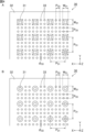
- FIG. 1 is a perspective view schematically showing an example of the heat diffusion device of the present invention.
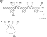
- FIG. 2 is an example of a cross-sectional view along line II-II of the heat spreading device shown in FIG. 3A is a partially enlarged cross-sectional view schematically showing an example of a wick constituting the heat diffusion device shown in FIG. 2.
- FIG. 3B is a perspective view schematically showing the shape of the convex portion of the wick shown in FIG. 3A.
- FIG. 3C is a perspective view schematically showing another example of the shape of the convex portion of the wick shown in FIG. 3A.
- FIG. FIG. 4A is an example of a plan view of the wick shown in FIG. 3A viewed from the support side.
- FIG. 4B is another example of a plan view of the wick shown in FIG. 3A viewed from the support side.
- FIG. 5 is a plan view schematically showing the flow of vapor in the through-holes, the projections, and the vicinity of the projections when the wick shown in FIG. 3A is viewed from the perforated body side.
- FIG. 6A is a partially enlarged cross-sectional view schematically showing a first modified example of the convex portion.
- FIG. 6B is a perspective view schematically showing the shape of the convex portion shown in FIG. 6A.
- FIG. 7A is a partially enlarged cross-sectional view schematically showing a second modification of the convex portion.
- FIG. 7B is a perspective view schematically showing the shape of the convex portion shown in FIG.
- FIG. 8-1A is a partially enlarged cross-sectional view schematically showing a third modified example of the projection.
- FIG. 8-1B is a perspective view schematically showing the shape of the projection shown in FIG. 8-1A.
- FIG. 8-2A is a partially enlarged sectional view schematically showing another example of the projection shown in FIG. 8-1A.
- FIG. 8-2B is a perspective view schematically showing the shape of the projection shown in FIG. 8-2A.
- FIG. 8-3A is a partially enlarged sectional view schematically showing another example of the projection shown in FIG. 8-1A.
- FIG. 8-3B is a perspective view schematically showing the shape of the projection shown in FIG. 8-3A.
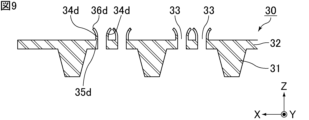
- FIG. 9 is a partially enlarged cross-sectional view schematically showing a fourth modified example of the projection.
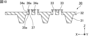
- FIG. 10 is a partially enlarged cross-sectional view schematically showing a fifth modification of the convex portion.
- FIG. 11 is a partially enlarged sectional view schematically showing a first modification of the wick.
- FIG. 12 is a partially enlarged cross-sectional view schematically showing a first modification of the convex portion in the wick shown in FIG. 11 .
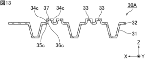
- FIG. 13 is a partially enlarged cross-sectional view schematically showing a second modification of the convex portion in the wick shown in FIG. 11 .
- FIG. 14 is a partially enlarged sectional view schematically showing a second modification of the wick.
- FIG. 15 is a plan view schematically showing a third modification of the wick.
- FIG. 16 is a cross-sectional view schematically showing a first modification of the heat diffusion device.
- FIG. 17 is a cross-sectional view schematically showing a second modification of the heat diffusion device.
- FIG. 18 is a plan view of the first modification of the wick shown in FIG. 3A, viewed from the perforated body side.
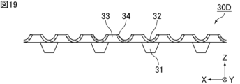
- FIG. 19 is a cross-sectional view of the wick shown in FIG. 18 along line AA.
- FIG. 20 is a diagram for explaining the definition of convex portions in the wick shown in FIG.
- FIG. 21 is a diagram for explaining the definition of convex portions in the wick shown in FIG. 19.
- FIG. 20 is a diagram for explaining the definition of convex portions in the wick shown in FIG.
- the heat diffusion device of the present invention will be described below.
- the present invention is not limited to the following embodiments, and can be appropriately modified and applied without changing the gist of the present invention.
- a combination of two or more of the individual preferred configurations of the present invention described below is also the present invention.
- a vapor chamber will be described below as an example of an embodiment of the heat diffusion device of the present invention.
- the heat diffusion device of the present invention can also be applied to heat diffusion devices such as heat pipes.
- FIG. 1 is a perspective view schematically showing an example of the heat diffusion device of the present invention.
- FIG. 2 is an example of a cross-sectional view along line II-II of the heat spreading device shown in FIG.
- a vapor chamber (heat diffusion device) 1 shown in FIGS. 1 and 2 includes a hollow casing 10 that is hermetically sealed.
- the housing 10 has a first inner wall surface 11a and a second inner wall surface 12a facing each other in the thickness direction Z.
- the vapor chamber 1 further includes a working medium 20 enclosed in the inner space of the housing 10 and a wick 30 arranged in the inner space of the housing 10 .
- An evaporator that evaporates the enclosed working medium 20 is set in the housing 10 .
- a heat source HS which is a heating element, is arranged on the outer wall surface of the housing 10 .
- the heat source HS include electronic components of electronic equipment, such as a central processing unit (CPU).
- CPU central processing unit
- a portion of the internal space of the housing 10 that is in the vicinity of the heat source HS and is heated by the heat source HS corresponds to the evaporator.
- the vapor chamber 1 is preferably planar as a whole. That is, the housing 10 as a whole is preferably planar.
- the “planar shape” includes a plate shape and a sheet shape, and the dimension in the width direction X (hereinafter referred to as width) and the dimension in the length direction Y (hereinafter referred to as length) are the thickness direction Z Shapes that are considerably large relative to their dimensions (hereinafter referred to as thickness or height), such as shapes whose width and length are 10 times or more, preferably 100 times or more, their thickness.
- the size of the vapor chamber 1, that is, the size of the housing 10 is not particularly limited.
- the width and length of the vapor chamber 1 can be appropriately set according to the application.
- the width and length of the vapor chamber 1 are, for example, 5 mm or more and 500 mm or less, 20 mm or more and 300 mm or less, or 50 mm or more and 200 mm or less.
- the width and length of the vapor chamber 1 may be the same or different.
- the housing 10 is preferably composed of a first sheet 11 and a second sheet 12 that face each other and whose outer edges are joined.
- the material of which the first sheet 11 and the second sheet 12 are composed should have properties suitable for use as a vapor chamber, such as thermal conductivity, strength, and the like. , flexibility, flexibility, etc., and is not particularly limited.
- the material that constitutes the first sheet 11 and the second sheet 12 is preferably a metal, such as copper, nickel, aluminum, magnesium, titanium, iron, or an alloy containing them as a main component, and copper is particularly preferable. is.
- the materials forming the first sheet 11 and the second sheet 12 may be the same or different, but are preferably the same.
- the housing 10 is composed of the first sheet 11 and the second sheet 12
- the first sheet 11 and the second sheet 12 are joined together at their outer edge portions.
- the method of such bonding is not particularly limited, but for example, laser welding, resistance welding, diffusion bonding, brazing, TIG welding (tungsten-inert gas welding), ultrasonic bonding or resin sealing can be used, which is preferable. can use laser welding, resistance welding or brazing.
- the thicknesses of the first sheet 11 and the second sheet 12 are not particularly limited, but each is preferably 10 ⁇ m or more and 200 ⁇ m or less, more preferably 30 ⁇ m or more and 100 ⁇ m or less, still more preferably 40 ⁇ m or more and 60 ⁇ m or less.
- the thicknesses of the first sheet 11 and the second sheet 12 may be the same or different. Also, the thickness of each sheet of the first sheet 11 and the second sheet 12 may be the same over the entire area, or may be thin in part.
- first sheet 11 and the second sheet 12 are not particularly limited.
- first sheet 11 and the second sheet 12 may each have a shape in which the outer edges are thicker than the portions other than the outer edges.
- the thickness of the entire vapor chamber 1 is not particularly limited, it is preferably 50 ⁇ m or more and 500 ⁇ m or less.
- the planar shape of the housing 10 when viewed from the thickness direction Z is not particularly limited, and examples thereof include polygonal shapes such as triangles and rectangles, circular shapes, elliptical shapes, and shapes combining these shapes. Further, the planar shape of the housing 10 may be L-shaped, C-shaped (U-shaped), step-shaped, or the like. Moreover, the housing 10 may have a through hole. The planar shape of the housing 10 may be a shape according to the use of the vapor chamber, the shape of the location where the vapor chamber is installed, and other parts existing nearby.
- the working medium 20 is not particularly limited as long as it can cause a gas-liquid phase change in the environment inside the housing 10.
- water, alcohols, CFC alternatives, etc. can be used.
- working medium 20 is an aqueous compound, preferably water.
- the wick 30 has a capillary structure that can move the working medium 20 by capillary force.
- the size and shape of the wick 30 are not particularly limited, it is preferable that the wicks 30 are arranged continuously in the internal space of the housing 10, for example.
- the wick 30 may be arranged in the entire internal space of the housing 10 when viewed from the thickness direction Z, or the wick 30 may be arranged in a part of the internal space of the housing 10 when viewed from the thickness direction Z. may be
- FIG. 3A is a partially enlarged cross-sectional view schematically showing an example of a wick that constitutes the heat diffusion device shown in FIG.
- the wick 30 includes a support 31 in contact with the first inner wall surface 11a and a perforated body 32 in contact with the support 31. As shown in FIGS. 2 and 3A, the wick 30 includes a support 31 in contact with the first inner wall surface 11a and a perforated body 32 in contact with the support 31. As shown in FIGS.
- the perforated body 32 is composed of the same material as the support 31.
- the material constituting the support 31 and the perforated body 32 is not particularly limited. Examples include laminates.
- a metal is preferable for the material constituting the support 31 and the perforated body 32 .
- the support 31 and the perforated body 32 may be constructed integrally.
- “the support 31 and the perforated body 32 are integrated” means that there is no interface between the support 31 and the perforated body 32. Specifically, , means that the boundary between the support 31 and the perforated body 32 cannot be distinguished.
- the wick 30 in which the support 31 and the perforated body 32 are integrally formed can be produced, for example, by etching technology, printing technology using multi-layer coating, or other multi-layer technology.
- the support 31 and the perforated body 32 may not be integrally formed.
- the entire surface between the support 31 and the perforated body 32 is Since it is difficult to join over the entire surface, a gap is generated in a part between the support 31 and the perforated body 32 .
- the support 31 and the perforated body 32 are not integrally constructed, but the perforated body 32 It can be said that it is made of the same material as the support 31 .
- FIG. 4A is an example of a plan view of the wick shown in FIG. 3A viewed from the support side.
- FIG. 4B is another example of a plan view of the wick shown in FIG. 3A viewed from the support side.
- the support 31 includes, for example, multiple columnar members.
- columnar means a shape in which the ratio of the length of the long side of the bottom surface is less than five times the length of the short side of the bottom surface.
- the shape of the columnar member is not particularly limited, examples thereof include a cylindrical shape, a prismatic shape, a truncated cone shape, and a truncated pyramid shape.
- the cross-sectional shape of the support 31 perpendicular to the height direction is rectangular, and in the example shown in FIG. 4B, the cross-sectional shape of the support 31 perpendicular to the height direction is circular.
- the columnar member should be relatively taller than its surroundings. Therefore, the columnar member includes, in addition to the portion protruding from the first inner wall surface 11a, a portion relatively high due to the depression formed in the first inner wall surface 11a.
- the shape of the support 31 is not particularly limited, but as shown in FIGS. 2 and 3A, the support 31 preferably has a tapered shape in which the width narrows from the perforated body 32 toward the first inner wall surface 11a. .
- the support 31 preferably has a tapered shape in which the width narrows from the perforated body 32 toward the first inner wall surface 11a.
- the arrangement of the supports 31 is not particularly limited, they are preferably arranged evenly in a predetermined area, more preferably evenly over the entire area, for example, so that the center-to-center distance (pitch) of the supports 31 is constant.
- the center-to-center distance of the support 31 (the length indicated by P31 in FIG. 4A or 4B) is, for example, 60 ⁇ m or more and 800 ⁇ m or less.
- the width of the support 31 (the length indicated by W31 in FIG. 4A or 4B) is, for example, 20 ⁇ m or more and 500 ⁇ m or less.
- the height of the support 31 (the length indicated by T31 in FIG. 3A) is, for example, 10 ⁇ m or more and 100 ⁇ m or less.
- the perforated body 32 has a through hole 33 penetrating in the thickness direction Z. Within the through hole 33, the working medium 20 can move by capillary action.
- the through hole 33 is preferably provided in a portion where the support 31 does not exist when viewed from the thickness direction Z. As shown in FIG. Although the shape of the through hole 33 is not particularly limited, it is preferable that the cross section of the plane perpendicular to the thickness direction Z is circular or elliptical.
- the arrangement of the through holes 33 of the perforated body 32 is not particularly limited. are arranged so that is constant.
- the center-to-center distance (the length indicated by P33 in FIG. 4A or 4B) of the through holes 33 of the perforated body 32 is, for example, 3 ⁇ m or more and 150 ⁇ m or less.
- the diameter of the end surface of the through-hole 33 on the side of the second inner wall surface 12a is, for example, 100 ⁇ m or less.
- the thickness of the perforated body 32 (the length indicated by T32 in FIG. 3A) is, for example, 5 ⁇ m or more and 50 ⁇ m or less.
- the thickness of the perforated body 32 means the thickness of the perforated body 32 at a portion where the later-described projections 34 are not provided.
- a protruding portion 34 is provided on the periphery of the through hole 33 so as to approach the second inner wall surface 12a.
- FIG. 3B is a perspective view schematically showing the shape of the convex portion of the wick shown in FIG. 3A.
- the convex portion 34 has a first end 35 on the side of the first inner wall surface 11a and a second end 36 on the side of the second inner wall surface 12a.
- the convex portion 34 has a cylindrical shape.
- the shape of the convex portion 34 is, for example, a cylindrical shape with a flat second end portion 36 .
- the shape of the convex portion 34 may be a square tube shape, or a hollow shape such as a truncated cone or a truncated pyramid.
- FIG. 5 is a plan view schematically showing the flow of steam in the vicinity of the through-holes, the projections, and the projections when the wick shown in FIG. 3A is viewed from the perforated body side.
- the working medium 20 evaporated in the heat source HS flows in a vapor state through the space between the perforated body 32 and the second inner wall surface 12a in a direction away from the heat source HS.
- a convex portion 34 is provided on the periphery of the through-hole 33 in a direction approaching the second inner wall surface 12a, the space between the perforated body 32 and the second inner wall surface 12a is reduced.
- the flowing steam flows so as to bypass the outer peripheral edges of the projections 34 . Therefore, it is possible to prevent the steam flow from directly contacting the liquid surface of the working medium 20 in the through hole 33 . Therefore, it is possible to reduce the effect of vapor flow in the direction opposite to the capillary force of the wick 30, that is, the so-called counterflow. Therefore, the maximum heat transfer amount of the vapor chamber 1 can be improved.
- the convex portion 34 is provided along the entire periphery of the through hole 33 .
- the convex portion 34 may be provided only on a part of the periphery of the through hole 33 .
- the protrusions 34 may be provided around all the through holes 33 in the perforated body 32 , or only around some of the through holes 33 in the perforated body 32 . When the protrusions 34 are provided only along the periphery of some of the through holes 33 in the perforated body 32, the protrusions 34 may be provided along the periphery of the perforations other than the through holes 33 positioned directly above the heat source HS. preferable.
- the through holes 33 and the projections 34 can be produced, for example, by punching the metal or the like that constitutes the perforated body 32 by press working.
- punching by press working the formation of the projections, the shape of the projections, and the like can be adjusted by appropriately adjusting the punching depth and the like.
- the punching depth means, for example, how far the punch is pushed in the punching direction when punching with a punch.
- the dimensions of the convex portion 34 are not particularly limited.
- the height of the protrusion 34 may be greater than the diameter of the through hole 33, or the height of the protrusion 34 may be smaller than the diameter of the through hole 33, and the height of the protrusion 34 may be It may be the same as the diameter of the through hole 33 .
- the height of the protrusion 34 means the distance in the thickness direction Z between the first end 35 and the second end 36. As shown in FIG.
- FIG. 3C is a perspective view schematically showing another example of the shape of the convex portion of the wick shown in FIG. 3A.
- the second end portion 36 is uneven, not flat.
- the height of the projection 34 is the maximum of the distances in the thickness direction Z between the first end 35 and the second end 36. means distance.
- FIG. 6A is a partially enlarged cross-sectional view schematically showing a first modified example of the convex portion.
- FIG. 6B is a perspective view schematically showing the shape of the convex portion shown in FIG. 6A.
- the projection 34a shown in FIGS. 6A and 6B has a first end 35a on the side of the first inner wall surface 11a and a second end 36a on the side of the second inner wall surface 12a.
- the cross-sectional area of the region surrounded by the inner wall of the second end portion 36a is smaller than the cross-sectional area of the region surrounded by the inner wall of the first end portion 35a.
- the cross-sectional area of the region surrounded by the inner wall of the second end portion 36 a when viewed from the thickness direction Z is smaller than the cross-sectional area of the region surrounded by the inner wall of the first end portion 35 a , the flow of steam is restricted in the through hole 33 . Direct contact with the liquid surface of the working medium 20 can be further prevented. As a result, the influence of the counterflow can be further reduced, so that the maximum heat transfer amount of the vapor chamber 1 can be further improved.
- the inner wall of the second end portion 36a is located inside the inner wall of the first end portion 35a when viewed from the thickness direction Z.
- the steam flow directly contacts the liquid surface of the working medium 20 in the through hole 33. can be further prevented.
- the influence of the counterflow can be further reduced, so that the maximum heat transfer amount of the vapor chamber 1 can be further improved.
- the convex portion 34a has a tapered shape in a cross section along the thickness direction Z such that the distance between the outer walls of the convex portion 34a becomes narrower toward the second inner wall surface 12a.
- the protrusion 34a has a tapered shape in which the distance between the outer walls of the protrusion 34a becomes narrower toward the second inner wall surface 12a, the perforated body 32 and the second inner wall surface 12a are tapered.
- the distance between the outer walls of the convex portion 34a becomes narrower toward the second inner wall surface 12a, compared to the convex portion 34 that does not have a tapered shape. It is possible to increase the flow path of the steam in contact with 34a. As a result, a decrease in thermal conductivity of the vapor chamber 1 can be suppressed.
- the convex portion 34a has a shape convex toward the second inner wall surface 12a side (upward in FIG. 6A) in a cross section along the thickness direction Z. In other words, the convex portion 34a curves toward the second inner wall surface 12a (upward in FIG. 6A) with respect to a line segment connecting the first end portion 35a and the second end portion 36a in a cross section along the thickness direction Z. Shape.
- FIG. 7A is a partially enlarged cross-sectional view schematically showing a second modification of the convex portion.
- FIG. 7B is a perspective view schematically showing the shape of the convex portion shown in FIG. 7A.
- the convex portion 34b shown in FIGS. 7A and 7B has a first end 35b on the side of the first inner wall surface 11a and a second end 36b on the side of the second inner wall surface 12a.
- the convex portion 34b has a tapered shape in a cross section along the thickness direction Z such that the distance between the outer walls of the convex portion 34b becomes narrower toward the second inner wall surface 12a.
- the convex portion 34b has a shape convex toward the first inner wall surface 11a side (lower side in FIG. 7A) in a cross section along the thickness direction Z. As shown in FIG. In other words, the convex portion 34b curves toward the first inner wall surface 11a (downward in FIG.
- FIG. 8-1A is a partially enlarged cross-sectional view schematically showing a third modified example of the convex portion.
- FIG. 8-1B is a perspective view schematically showing the shape of the projection shown in FIG. 8-1A.
- the projection 34c shown in FIGS. 8-1A and 8-1B has a first end 35c on the side of the first inner wall surface 11a and a second end 36c on the side of the second inner wall surface 12a.
- the cross-sectional area of the region surrounded by the inner wall of the second end portion 36c is smaller than the cross-sectional area of the region surrounded by the inner wall of the first end portion 35c.
- the convex portion 34c has a lid portion 37 that narrows the opening of the convex portion 34c at the second end portion 36c.
- the convex portion 34c when viewed from the thickness direction Z, the cross-sectional area of the region surrounded by the inner wall of the second end portion 36c is narrower than the convex portion 34b in which the lid portion 37 does not exist at the second end portion 36c.
- the convex portion 34c is provided with a lid portion 37 that narrows the opening of the convex portion 34c at the second end portion 36c, the flow of steam is further prevented from directly contacting the liquid surface of the working medium 20 in the through hole 33. can be done. As a result, the influence of the counterflow can be further reduced, so that the maximum heat transfer amount of the vapor chamber 1 can be further improved.
- the lid portion 37 that narrows the opening of the convex portion 34c may be formed, for example, by pressing the second end portion 36c.
- the size and shape of the lid portion 37 that narrows the opening of the convex portion 34c are not particularly limited as long as the opening on the second end portion 36c side of the convex portion 34c is narrowed.
- the lid portion 37 that narrows the opening of the convex portion 34c preferably has a flat surface.
- the lid portion 37 that narrows the opening of the convex portion 34c is preferably a flat surface perpendicular to the thickness direction Z. As shown in FIG. A part or the whole of the lid portion 37 that narrows the opening of the convex portion 34c may be curved.
- the lid portion 37 that narrows the opening of the convex portion 34c may have an uneven surface.
- the thickness of the lid portion 37 that narrows the opening of the convex portion 34c may be the same as or different from the thickness of the convex portion 34c.
- the lid portion 37 is provided over the entire second end portion 36c. 8-1A and 8-1B, the center of the peripheral edge of the through-hole 33 at the first end 35c and the center of the peripheral edge of the through-hole 33 at the second end 36c are aligned.
- FIG. 8-2A is a partially enlarged sectional view schematically showing another example of the convex portion shown in FIG. 8-1A.
- FIG. 8-2B is a perspective view schematically showing the shape of the projection shown in FIG. 8-2A.
- the lid portion 37 is provided only on part of the second end portion 36c.
- the lid portion 37 is provided only on the right side of the convex portion 34c, and the lid portion 37 is not provided on the left side of the convex portion 34c.
- the center of the peripheral edge of the through-hole 33 at the first end 35c and the center of the peripheral edge of the through-hole 33 at the second end 36c do not match.
- FIG. 8-3A is a partially enlarged sectional view schematically showing another example of the convex portion shown in FIG. 8-1A.
- FIG. 8-3B is a perspective view schematically showing the shape of the projection shown in FIG. 8-3A.
- the lid portion 37 is provided only on part of the second end portion 36c.
- the lid portion 37 is provided only on the right side of the convex portion 34c, and the lid portion 37 is not provided on the left side of the convex portion 34c.
- a lid portion 37 having a substantially circular cross section is provided on a portion of the second end portion 36c.
- the lid portion 37 is a flat surface perpendicular to the thickness direction Z, but FIGS.
- the lid portion 37 is provided so as to extend toward the second inner wall surface 12a side (the upper side in FIG. 8-3A). In FIGS. 8-3A and 8-3B, the lid portion 37 has a flat surface, but the lid portion 37 may have a curved surface.
- FIG. 9 is a partially enlarged cross-sectional view schematically showing a fourth modified example of the convex portion.
- a convex portion 34d shown in FIG. 9 has a first end 35d on the side of the first inner wall surface 11a and a second end 36d on the side of the second inner wall surface 12a.
- the cross-sectional area of the region surrounded by the inner wall of the second end portion 36d is larger than the cross-sectional area of the region surrounded by the inner wall of the first end portion 35d.
- the inner wall of the second end portion 36d is located outside the inner wall of the first end portion 35d when viewed from the thickness direction Z.
- FIG. 10 is a partially enlarged cross-sectional view schematically showing a fifth modified example of the convex portion.
- the convex portion 34e shown in FIG. 10 has a first end 35e on the side of the first inner wall surface 11a and a second end 36e on the side of the second inner wall surface 12a.
- the cross-sectional area of the region surrounded by the inner wall of the second end portion 36e is larger than the cross-sectional area of the region surrounded by the inner wall of the first end portion 35e.
- the convex portion 34e has a lid portion 37 that narrows the opening of the convex portion 34e at the second end portion 36e.
- the convex portion 34e when viewed from the thickness direction Z, the cross-sectional area of the region surrounded by the inner wall of the second end portion 36e is narrower than that of the convex portion 34d in which the lid portion 37 does not exist at the second end portion 36e.
- the convex portion 34e is provided with a lid portion 37 that narrows the opening of the convex portion 34e at the second end portion 36e, the flow of steam is further prevented from directly contacting the liquid surface of the working medium 20 in the through hole 33. can be done. As a result, the influence of the counterflow can be further reduced, so that the maximum heat transfer amount of the vapor chamber 1 can be further improved.
- the lid portion 37 that narrows the opening of the convex portion 34e may be formed, for example, by pressing the second end portion 36e.
- the size and shape of the lid portion 37 that narrows the opening of the convex portion 34e are not particularly limited as long as the opening on the second end portion 36e side of the convex portion 34e is narrowed.
- the lid portion 37 that narrows the opening of the convex portion 34e preferably has a flat surface.
- the lid portion 37 that narrows the opening of the convex portion 34e preferably has a flat surface perpendicular to the thickness direction Z. As shown in FIG. A part or the whole of the lid portion 37 that narrows the opening of the convex portion 34e may be curved.
- the lid portion 37 that narrows the opening of the convex portion 34e may have an uneven surface.
- the thickness of the lid portion 37 that narrows the opening of the convex portion 34e may be the same as or different from the thickness of the convex portion 34e.
- FIG. 11 is a partially enlarged sectional view schematically showing a first modification of the wick.
- a support 31 is formed in the recessed portion by bending and recessing a portion of the metal foil by press working or the like.
- a vapor space is formed in the recessed portion of the support 31, thereby improving thermal conductivity.
- a through hole may be formed in a recessed portion when a part of the metal foil is bent.
- the thickness of the metal foil is constant before performing press working or the like. However, the metal foil may become thin at the bent portion. From the above, in the wick 30A, it is preferable that the thickness of the support 31 is the same as the thickness of the perforated body 32 or smaller than the thickness of the perforated body 32 .
- the wick 30A is preferably formed by collectively performing press work for forming the support 31 and press work for forming the through holes 33 and the projections 34 .
- the thickness of the projections 34 may be the same as the thickness of the support 31.
- the thickness of the protrusions 34 may be the same as the thickness of the perforated body 32 .
- the thickness of the support 31, the thickness of the perforated body 32, and the thickness of the projections 34 may be constant.
- the thickness of the projections 34 may be different from the thickness of the support 31. In the wick 30A, the thickness of the projections 34 may differ from the thickness of the perforated body 32. FIG.
- FIG. 12 is a partially enlarged cross-sectional view schematically showing a first modification of the convex portion in the wick shown in FIG.
- the convex portion 34b shown in FIG. 12 has the same shape as the convex portion 34b shown in FIGS. 7A and 7B.
- the protrusion 34b has a first end 35b on the side of the first inner wall surface 11a and a second end 36b on the side of the second inner wall surface 12a.
- the convex portion 34b has a tapered shape in a cross section along the thickness direction Z such that the distance between the outer walls of the convex portion 34b becomes narrower toward the second inner wall surface 12a.
- the convex portion 34b has a shape convex toward the first inner wall surface 11a side (lower side in FIG. 12) in a cross section along the thickness direction Z. As shown in FIG.
- the convex portion 34b curves toward the first inner wall surface 11a (downward in FIG. 12) with respect to a line segment connecting the first end portion 35b and the second end portion 36b in a cross section along the thickness direction Z. It is a shape that
- the thickness of the convex portion 34b may be the same as or different from the thickness of the support 31.
- the thickness of the protrusions 34b may be the same as or different from the thickness of the perforated body 32 .
- FIG. 13 is a partially enlarged cross-sectional view schematically showing a second modification of the convex portion in the wick shown in FIG.
- the convex portion 34c shown in FIG. 13 has the same shape as the convex portion 34c shown in FIGS. 8-1A and 8-1B.
- the protrusion 34c has a first end 35c on the first inner wall surface 11a side and a second end 36c on the second inner wall surface 12a side.
- the cross-sectional area of the region surrounded by the inner wall of the second end portion 36c is smaller than the cross-sectional area of the region surrounded by the inner wall of the first end portion 35c.
- the convex portion 34c has a lid portion 37 that narrows the opening of the convex portion 34c at the second end portion 36c.
- the thickness of the convex portion 34c may be the same as or different from the thickness of the support 31.
- the thickness of the convex portion 34c may be the same as the thickness of the perforated body 32, or may be different.
- the thickness of the lid portion 37 that narrows the opening of the convex portion 34c may be the same as or different from the thickness of the support 31 .
- the thickness of the lid portion 37 that narrows the opening of the convex portion 34c may be the same as or different from the thickness of the perforated body 32 .
- the convex portion 34 shown in FIG. 11 may have the same shape as the convex portion 34a shown in FIGS. 6A and 6B, the convex portion 34d shown in FIG. 9, or the convex portion 34e shown in FIG.
- FIG. 14 is a partially enlarged sectional view schematically showing a second modification of the wick.
- the perforated body 32 is made of a different material than the support 31.
- Materials constituting the support 31 are not particularly limited, but examples thereof include resins, metals, ceramics, or mixtures and laminates thereof.
- Materials constituting the perforated body 32 are not particularly limited, but examples thereof include resins, metals, ceramics, or mixtures and laminates thereof.
- Metal is preferable as the material for forming the perforated body 32 .
- the convex portion 34 shown in FIG. 14 includes the convex portion 34a shown in FIGS. 6A and 6B, the convex portion 34b shown in FIGS. 7A and 7B, the convex portion 34c shown in FIGS. 8-1A and 8-1B, and FIG. 8-2B, the projections 34c shown in FIGS. 8-3A and 8-3B, the projections 34d shown in FIG. 9, or the projections 34e shown in FIG. .
- FIG. 15 is a plan view schematically showing a third modification of the wick. Note that FIG. 15 is a plan view of the wick viewed from the support side.
- the support 31 includes a plurality of rail-shaped members.
- rail-like means a shape in which the ratio of the length of the long side of the bottom surface is five times or more the length of the short side of the bottom surface.
- the cross-sectional shape perpendicular to the extending direction of the rail-shaped member is not particularly limited, but examples thereof include polygonal shapes such as quadrangles, semicircular shapes, semielliptical shapes, and shapes in which these are combined.
- the rail-shaped member should be relatively taller than its surroundings. Therefore, the rail-shaped member includes not only the portion protruding from the first inner wall surface 11a, but also the relatively high portion due to the grooves formed in the first inner wall surface 11a.
- the wick 30C is not limited to the shape disclosed in FIG. 15, and may be used by being partially arranged instead of being arranged in the entire internal space.
- a rail-shaped support member 31 may be formed along the outer periphery in the internal space, and a perforated member 32 having a shape along the outer periphery may be arranged thereon.
- a pillar 40 may be arranged in the internal space of the housing 10 so as to contact the second inner wall surface 12a. It is possible to support the housing 10 and the wick 30 by arranging the struts 40 in the internal space of the housing 10 .
- the material forming the pillars 40 is not particularly limited, but examples thereof include resins, metals, ceramics, mixtures thereof, laminates, and the like.
- the support 40 may be integrated with the housing 10, or may be formed by etching the second inner wall surface 12a of the housing 10, for example.
- the shape of the support 40 is not particularly limited as long as it can support the housing 10 and the wick 30, but the shape of the cross section of the support 40 perpendicular to the height direction may be, for example, a polygon such as a rectangle, a circle, or an ellipse. shape, etc.
- the height of the struts 40 may be the same or different in one vapor chamber.
- the width of the support 40 is not particularly limited as long as it provides strength capable of suppressing deformation of the housing 10. is, for example, 100 ⁇ m or more and 2000 ⁇ m or less, preferably 300 ⁇ m or more and 1000 ⁇ m or less.
- the equivalent circle diameter of the strut 40 By increasing the equivalent circle diameter of the strut 40, the deformation of the housing 10 can be further suppressed.
- the equivalent circle diameter of the strut 40 it is possible to ensure a wider space for the vapor of the working medium 20 to move.
- the arrangement of the struts 40 is not particularly limited, they are preferably arranged evenly in a predetermined area, more preferably evenly over the entire area, for example, so that the distance between the struts 40 is constant. By arranging the struts 40 evenly, it is possible to ensure uniform strength throughout the vapor chamber 1 .
- FIG. 16 is a cross-sectional view schematically showing a first modification of the heat diffusion device.
- the support 31 is integrally formed with the first sheet 11 of the housing 10.
- the first sheet 11 and the support 31 can be produced by, for example, an etching technique, a printing technique using multi-layer coating, or other multi-layer techniques.
- the perforated body 32 is preferably made of a material different from that of the support 31 .
- the perforated body 32 may be made of the same material as the support 31 and the first sheet 11 of the housing 10, and the perforated body 32 is formed from the support 31 and the housing. It may be configured integrally with the ten first sheets 11 .
- FIG. 17 is a cross-sectional view schematically showing a second modification of the heat diffusion device.
- a support 31 is formed in the recessed portion by bending and recessing a portion of the first inner wall surface 11a of the housing 10 by press working or the like. ing.
- the heat diffusion device of the present invention is not limited to the above embodiments, and various applications and modifications can be made within the scope of the present invention regarding the configuration, manufacturing conditions, etc. of the heat diffusion device.
- FIG. 18 is a plan view of the first modification of the wick shown in FIG. 3A, viewed from the perforated body side.
- FIG. 19 is a cross-sectional view of the wick shown in FIG. 18 along line AA.
- FIG. 19 is a cross-sectional view passing through the through hole 33, but in a cross section along the thickness direction Z that does not pass through the through hole 33, there is a flat portion between the convex portions 34. It is also possible that there is no flat portion. Further, in the wick 30D, the perforated body 32 may be curved as a whole and may not have a flat portion.
- FIG. 20 is a diagram for explaining the definition of convex portions in the wick shown in FIG. FIG. 20 is the same diagram as FIG. 12 except that a straight line L1 and a straight line L2 are added.
- a convex portion is defined as a portion between a straight line L1 and a straight line L2 set as follows in a cross section along the thickness direction Z.
- the straight line L1 and the straight line L2 are set for each convex portion.
- straight lines L1 and L2 set in a cross-section along the thickness direction Z.
- a plane (XY plane) perpendicular to the thickness direction Z is called a reference plane.
- the straight line L1 and the straight line L2 will be described below using the wick 30A shown in FIG. 20 as an example.
- the straight line L1 is set as follows.
- L1 be a straight line that passes through the point (point P1 in FIG. 20) that is the shortest from the periphery on the side of the second inner wall surface 12a and that is parallel to the reference plane.
- the straight line L1 is set as follows.
- FIG. 21 is a diagram for explaining the definition of convex portions in the wick shown in FIG.
- the straight line L1 is set as follows.
- L1 be a straight line that passes through a point that is the shortest from the edge of the inner wall surface 12a and that is parallel to the reference plane.
- An inflection point refers to a point at which unevenness changes on a curve, that is, a point at which a downward convex is switched to an upward convex, or a point at which an upward convex is switched to a downward convex.
- An inflection point means a point that cannot be differentiated, such as an intersection of straight lines with different slopes or an intersection of a straight line and a curved line.
- the lid portion 37 may satisfy the conditions described in (2-1), (2-2) or (2-3). is satisfied, the part parallel to the reference plane in (2-1), the part where the tangent line in (2-2) is parallel to the reference plane, or the inflection in (2-3) It shall not be considered as a part where points or inflection points exist.
- the portion of the wick 30A on the straight line L1 is the first end portion 35b.
- the portion including the point at which the distance from the peripheral edge of the through hole 33 on the second inner wall surface 12a side is the shortest is the first end portion 35b.
- a portion from the first end portion 35b set in this way to the second end portion 36b becomes the convex portion 34b.
- the housing may have one evaporator or may have a plurality of evaporators. That is, one heat source may be arranged on the outer wall surface of the housing, or a plurality of heat sources may be arranged.
- the number of evaporators and heat sources is not particularly limited.
- the first sheet and the second sheet when the housing is composed of the first sheet and the second sheet, the first sheet and the second sheet may be overlapped so that their ends are aligned, or may be shifted and overlapped.
- the material of the first sheet and the material of the second sheet may be different.
- the stress applied to the housing can be dispersed.
- one sheet can have one function and the other sheet can have another function.
- the above functions are not particularly limited, but include, for example, a heat conduction function, an electromagnetic wave shielding function, and the like.
- the heat diffusion device of the present invention can be mounted on electronic equipment for the purpose of heat dissipation. Therefore, an electronic device including the heat diffusion device of the present invention is also one aspect of the present invention.
- Examples of the electronic device of the present invention include smart phones, tablet terminals, notebook computers, game machines, wearable devices, and the like.
- the heat diffusion device of the present invention operates independently without the need for external power, and utilizes the latent heat of vaporization and latent heat of condensation of the working medium to diffuse heat two-dimensionally and at high speed. Therefore, an electronic device equipped with the heat diffusion device of the present invention can effectively dissipate heat in a limited space inside the electronic device.
- the heat diffusion device of the present invention can be used for a wide range of applications in fields such as personal digital assistants. For example, it can be used to lower the temperature of a heat source such as a CPU and extend the operating time of electronic equipment, and can be used in smartphones, tablet terminals, laptop computers, and the like.
- 1, 1A, 1B vapor chamber (heat diffusion device) 10 housing 11 first sheet 11a first inner wall surface 12 second sheet 12a second inner wall surface 20 working medium 30, 30A, 30B, 30C, 30D wick 31 support 32 perforated body 33 through holes 34, 34a, 34b, 34c, 34d, 34e Projection 35, 35a, 35b, 35c, 35d, 35e First end 36, 36a, 36b, 36c, 36d, 36e Second end 37 Lid 40 Post HS Heat source P Center of 31 support Distance between P center-to-center distance of 33 through-holes T 31 height of support T 32 thickness of perforated body W width of 31 support X width direction Y length direction Z thickness direction ⁇ 33 second inside of through-hole Diameter at the end face on the wall side
Abstract
A thermal diffusion device 1 comprising : a housing 10 that has a first inner wall surface 11a and a second inner wall surface 12a facing one another in the thickness direction Z; a working medium 20 that is enclosed in an internal space of the housing 10; and a wick 30 that is disposed in said internal space of the housing 10. The wick 30 includes: a support body 31 in contact with the first inner wall surface 11a; and a porous body 32 in contact with the support body 31. The porous body 32 has through-holes 33 in the thickness direction Z. The circumference of the through-holes 33 is provided with a protrusion 34 in a direction so as to approach the second inner wall surface 12a.
Description
本発明は、熱拡散デバイス及び電子機器に関する。
The present invention relates to heat diffusion devices and electronic equipment.
近年、素子の高集積化及び高性能化による発熱量が増加している。また、製品の小型化が進むことで、発熱密度が増加するため、放熱対策が重要となっている。この状況はスマートフォン及びタブレットなどのモバイル端末の分野において特に顕著である。熱対策部材としては、グラファイトシートなどが用いられることが多いが、その熱輸送量は充分ではないため、様々な熱対策部材の使用が検討されている。中でも、非常に効果的に熱を拡散させることが可能である熱拡散デバイスとして、面状のヒートパイプであるベーパーチャンバーの使用の検討が進んでいる。
In recent years, the amount of heat generated has increased due to the high integration and high performance of devices. In addition, as products become smaller, heat generation density increases, so heat dissipation measures are becoming important. This situation is particularly pronounced in the field of mobile terminals such as smartphones and tablets. A graphite sheet or the like is often used as a heat countermeasure member, but its heat transfer capacity is not sufficient, so the use of various heat countermeasure members has been investigated. Among them, as a heat diffusion device capable of diffusing heat very effectively, the use of a vapor chamber, which is a planar heat pipe, is being studied.
ベーパーチャンバーは、筐体の内部に、作動媒体(作動流体ともいう)と、毛細管力によって作動媒体を輸送するウィックとが封入された構造を有する。作動媒体は、電子部品などの発熱素子からの熱を吸収する蒸発部において発熱素子からの熱を吸収してベーパーチャンバー内で蒸発した後、ベーパーチャンバー内を移動し、冷却されて液相に戻る。液相に戻った作動媒体は、ウィックの毛細管力によって再び発熱素子側の蒸発部に移動し、発熱素子を冷却する。これを繰り返すことにより、ベーパーチャンバーは外部動力を有することなく自立的に作動し、作動媒体の蒸発潜熱及び凝縮潜熱を利用して、二次元的に高速で熱を拡散することができる。
A vapor chamber has a structure in which a working medium (also called a working fluid) and a wick that transports the working medium by capillary force are sealed inside a housing. The working medium absorbs heat from the heat-generating elements such as electronic parts in the evaporator, evaporates in the vapor chamber, moves in the vapor chamber, is cooled, and returns to the liquid phase. . The working medium that has returned to the liquid phase moves again to the evaporating portion on the heating element side by the capillary force of the wick, and cools the heating element. By repeating this, the vapor chamber can operate independently without external power, and heat can be two-dimensionally diffused at high speed by utilizing the latent heat of vaporization and latent heat of condensation of the working medium.
特許文献1には、ベーパーチャンバーの一例であるサーマルグラウンドプレーン(thermal ground plane)が開示されている。特許文献1に記載のサーマルグラウンドプレーンは、第1の面状基材(planar substrate member)と、上記第1の面状基材に配置される複数のマイクロピラーと、少なくとも一部の上記マイクロピラーに接着されるメッシュと、上記第1の面状基材、上記マイクロピラー及び上記メッシュのうちの少なくとも1つに配置される蒸気コア(vapor core)と、上記第1の面状基材に配置される第2の面状基材と、を備え、上記メッシュは上記マイクロピラーを上記蒸気コアから分離し、上記第1の面状基材及び上記第2の面状基材は上記マイクロピラー、上記メッシュ及び上記蒸気コアを取り囲んでいる。
Patent Document 1 discloses a thermal ground plane, which is an example of a vapor chamber. The thermal ground plane described in Patent Document 1 includes a first planar substrate member, a plurality of micropillars arranged on the first planar substrate, and at least some of the micropillars a vapor core disposed on at least one of said first planar substrate, said micropillars and said mesh; and disposed on said first planar substrate. wherein the mesh separates the micropillars from the vapor core, the first planar substrate and the second planar substrate are connected to the micropillars; Surrounding the mesh and the steam core.
特許文献1に記載されているようなベーパーチャンバーでは、マイクロピラーなどの支柱とメッシュなどの有孔体とによりウィックが構成されている。ベーパーチャンバーの有孔体としては、エッチング加工などによって、金属板に孔部を形成した有孔体などが用いられる。このような有孔体では、蒸気層と接する部分において、有孔体の表面と、孔部の周縁で囲まれる面と、が互いに面一となっている。このとき、孔部内の作動媒体の液面が蒸気層と接するため、蒸気層での蒸気の流れが孔部内の作動媒体に与える影響が大きい。以上により、特許文献1に記載されているようなベーパーチャンバーでは、毛細管力とは逆方向への蒸気の流れ、いわゆるカウンターフローの影響をウィックが受けやすいため、カウンターフローによってウィックの毛細管力が減少することで、ベーパーチャンバーの最大熱輸送量が低下してしまうという問題がある。
In the vapor chamber as described in Patent Document 1, a wick is composed of struts such as micropillars and perforated bodies such as mesh. As the perforated body of the vapor chamber, a perforated body obtained by forming holes in a metal plate by etching or the like is used. In such a perforated body, the surface of the perforated body and the surface surrounded by the peripheries of the perforations are flush with each other in the portion in contact with the vapor layer. At this time, since the liquid surface of the working medium in the holes is in contact with the vapor layer, the flow of vapor in the vapor layer greatly affects the working medium in the holes. As described above, in the vapor chamber as described in Patent Document 1, the wick is easily affected by the flow of vapor in the direction opposite to the capillary force, the so-called counterflow, so the counterflow reduces the capillary force of the wick. As a result, there is a problem that the maximum heat transfer amount of the vapor chamber is lowered.
本発明は、上記の問題を解決するためになされたものであり、最大熱輸送量を向上可能な熱拡散デバイスを提供することを目的とする。さらに、本発明は、上記熱拡散デバイスを備える電子機器を提供することを目的とする。
The present invention has been made to solve the above problems, and an object of the present invention is to provide a heat diffusion device capable of improving the maximum amount of heat transport. A further object of the present invention is to provide an electronic device comprising the above heat diffusion device.
本発明の熱拡散デバイスは、厚さ方向に対向する第1内壁面及び第2内壁面を有する筐体と、上記筐体の内部空間に封入される作動媒体と、上記筐体の上記内部空間に配置されるウィックと、を備え、上記ウィックは、上記第1内壁面に接する支持体と、上記支持体に接する有孔体と、を含み、上記有孔体は上記厚さ方向に貫通する貫通孔を有し、上記貫通孔の周縁には、上記第2内壁面に近接する方向に凸部が設けられている。
A heat diffusion device of the present invention comprises a housing having a first inner wall surface and a second inner wall surface facing each other in a thickness direction, a working medium enclosed in an internal space of the housing, and the internal space of the housing. the wick includes a support in contact with the first inner wall surface and a perforated body in contact with the support, the perforated body penetrating in the thickness direction A through hole is provided, and a protrusion is provided on the periphery of the through hole in a direction approaching the second inner wall surface.
本発明の電子機器は、本発明の熱拡散デバイスを備える。
The electronic device of the present invention includes the heat diffusion device of the present invention.
本発明によれば、最大熱輸送量を向上可能な熱拡散デバイスを提供することができる。さらに、本発明によれば、上記熱拡散デバイスを備える電子機器を提供することができる。
According to the present invention, it is possible to provide a heat diffusion device capable of improving the maximum amount of heat transport. Furthermore, according to the present invention, it is possible to provide an electronic device comprising the above heat diffusion device.
以下、本発明の熱拡散デバイスについて説明する。
しかしながら、本発明は、以下の実施形態に限定されるものではなく、本発明の要旨を変更しない範囲において適宜変更して適用することができる。なお、以下において記載する本発明の個々の好ましい構成を2つ以上組み合わせたものもまた本発明である。 The heat diffusion device of the present invention will be described below.
However, the present invention is not limited to the following embodiments, and can be appropriately modified and applied without changing the gist of the present invention. A combination of two or more of the individual preferred configurations of the present invention described below is also the present invention.
以下では、本発明の熱拡散デバイスの一実施形態として、ベーパーチャンバーを例にとって説明する。本発明の熱拡散デバイスは、ヒートパイプ等の熱拡散デバイスにも適用可能である。
A vapor chamber will be described below as an example of an embodiment of the heat diffusion device of the present invention. The heat diffusion device of the present invention can also be applied to heat diffusion devices such as heat pipes.
以下に示す図面は模式的なものであり、その寸法や縦横比の縮尺などは実際の製品とは異なる場合がある。
The drawings shown below are schematic, and their dimensions and aspect ratio may differ from the actual product.
図1は、本発明の熱拡散デバイスの一例を模式的に示す斜視図である。図2は、図1に示す熱拡散デバイスのII-II線に沿った断面図の一例である。
FIG. 1 is a perspective view schematically showing an example of the heat diffusion device of the present invention. FIG. 2 is an example of a cross-sectional view along line II-II of the heat spreading device shown in FIG.
図1及び図2に示すベーパーチャンバー(熱拡散デバイス)1は、気密状態に密閉された中空の筐体10を備える。筐体10は、厚さ方向Zに対向する第1内壁面11a及び第2内壁面12aを有する。ベーパーチャンバー1は、さらに、筐体10の内部空間に封入される作動媒体20と、筐体10の内部空間に配置されるウィック30と、を備える。
A vapor chamber (heat diffusion device) 1 shown in FIGS. 1 and 2 includes a hollow casing 10 that is hermetically sealed. The housing 10 has a first inner wall surface 11a and a second inner wall surface 12a facing each other in the thickness direction Z. As shown in FIG. The vapor chamber 1 further includes a working medium 20 enclosed in the inner space of the housing 10 and a wick 30 arranged in the inner space of the housing 10 .
筐体10には、封入した作動媒体20を蒸発させる蒸発部が設定される。図1に示すように、筐体10の外壁面には、発熱素子である熱源(heat source)HSが配置される。熱源HSとしては、電子機器の電子部品、例えば中央処理装置(CPU)等が挙げられる。筐体10の内部空間のうち、熱源HSの近傍であって熱源HSによって加熱される部分が、蒸発部に相当する。
An evaporator that evaporates the enclosed working medium 20 is set in the housing 10 . As shown in FIG. 1, a heat source HS, which is a heating element, is arranged on the outer wall surface of the housing 10 . Examples of the heat source HS include electronic components of electronic equipment, such as a central processing unit (CPU). A portion of the internal space of the housing 10 that is in the vicinity of the heat source HS and is heated by the heat source HS corresponds to the evaporator.
ベーパーチャンバー1は、全体として面状であることが好ましい。すなわち、筐体10は、全体として面状であることが好ましい。ここで、「面状」とは、板状及びシート状を包含し、幅方向Xの寸法(以下、幅という)及び長さ方向Yの寸法(以下、長さという)が厚さ方向Zの寸法(以下、厚さ又は高さという)に対して相当に大きい形状、例えば幅及び長さが、厚さの10倍以上、好ましくは100倍以上である形状を意味する。
The vapor chamber 1 is preferably planar as a whole. That is, the housing 10 as a whole is preferably planar. Here, the “planar shape” includes a plate shape and a sheet shape, and the dimension in the width direction X (hereinafter referred to as width) and the dimension in the length direction Y (hereinafter referred to as length) are the thickness direction Z Shapes that are considerably large relative to their dimensions (hereinafter referred to as thickness or height), such as shapes whose width and length are 10 times or more, preferably 100 times or more, their thickness.
ベーパーチャンバー1の大きさ、すなわち、筐体10の大きさは、特に限定されない。ベーパーチャンバー1の幅及び長さは、用途に応じて適宜設定することができる。ベーパーチャンバー1の幅及び長さは、各々、例えば、5mm以上500mm以下、20mm以上300mm以下又は50mm以上200mm以下である。ベーパーチャンバー1の幅及び長さは、同じであってもよく、異なっていてもよい。
The size of the vapor chamber 1, that is, the size of the housing 10 is not particularly limited. The width and length of the vapor chamber 1 can be appropriately set according to the application. The width and length of the vapor chamber 1 are, for example, 5 mm or more and 500 mm or less, 20 mm or more and 300 mm or less, or 50 mm or more and 200 mm or less. The width and length of the vapor chamber 1 may be the same or different.
筐体10は、外縁部が接合された対向する第1シート11及び第2シート12から構成されることが好ましい。
The housing 10 is preferably composed of a first sheet 11 and a second sheet 12 that face each other and whose outer edges are joined.
筐体10が第1シート11及び第2シート12から構成される場合、第1シート11及び第2シート12を構成する材料は、ベーパーチャンバーとして用いるのに適した特性、例えば熱伝導性、強度、柔軟性、可撓性等を有するものであれば、特に限定されない。第1シート11及び第2シート12を構成する材料は、好ましくは金属であり、例えば銅、ニッケル、アルミニウム、マグネシウム、チタン、鉄、又はそれらを主成分とする合金等であり、特に好ましくは銅である。第1シート11及び第2シート12を構成する材料は、同じであってもよく、異なっていてもよいが、好ましくは同じである。
When the housing 10 is composed of the first sheet 11 and the second sheet 12, the material of which the first sheet 11 and the second sheet 12 are composed should have properties suitable for use as a vapor chamber, such as thermal conductivity, strength, and the like. , flexibility, flexibility, etc., and is not particularly limited. The material that constitutes the first sheet 11 and the second sheet 12 is preferably a metal, such as copper, nickel, aluminum, magnesium, titanium, iron, or an alloy containing them as a main component, and copper is particularly preferable. is. The materials forming the first sheet 11 and the second sheet 12 may be the same or different, but are preferably the same.
筐体10が第1シート11及び第2シート12から構成される場合、第1シート11及び第2シート12は、これらの外縁部において互いに接合される。かかる接合の方法は、特に限定されないが、例えば、レーザー溶接、抵抗溶接、拡散接合、ロウ接、TIG溶接(タングステン-不活性ガス溶接)、超音波接合又は樹脂封止を用いることができ、好ましくはレーザー溶接、抵抗溶接又はロウ接を用いることができる。
When the housing 10 is composed of the first sheet 11 and the second sheet 12, the first sheet 11 and the second sheet 12 are joined together at their outer edge portions. The method of such bonding is not particularly limited, but for example, laser welding, resistance welding, diffusion bonding, brazing, TIG welding (tungsten-inert gas welding), ultrasonic bonding or resin sealing can be used, which is preferable. can use laser welding, resistance welding or brazing.
第1シート11及び第2シート12の厚さは、特に限定されないが、各々、好ましくは10μm以上200μm以下、より好ましくは30μm以上100μm以下、さらに好ましくは40μm以上60μm以下である。第1シート11及び第2シート12の厚さは、同じであってもよく、異なっていてもよい。また、第1シート11及び第2シート12の各シートの厚さは、全体にわたって同じであってもよく、一部が薄くてもよい。
The thicknesses of the first sheet 11 and the second sheet 12 are not particularly limited, but each is preferably 10 μm or more and 200 μm or less, more preferably 30 μm or more and 100 μm or less, still more preferably 40 μm or more and 60 μm or less. The thicknesses of the first sheet 11 and the second sheet 12 may be the same or different. Also, the thickness of each sheet of the first sheet 11 and the second sheet 12 may be the same over the entire area, or may be thin in part.
第1シート11及び第2シート12の形状は、特に限定されない。例えば、第1シート11及び第2シート12は、各々、外縁部が外縁部以外の部分よりも厚い形状であってもよい。
The shapes of the first sheet 11 and the second sheet 12 are not particularly limited. For example, the first sheet 11 and the second sheet 12 may each have a shape in which the outer edges are thicker than the portions other than the outer edges.
ベーパーチャンバー1全体の厚さは、特に限定されないが、好ましくは50μm以上500μm以下である。
Although the thickness of the entire vapor chamber 1 is not particularly limited, it is preferably 50 μm or more and 500 μm or less.
厚さ方向Zから見た筐体10の平面形状は特に限定されず、例えば、三角形又は矩形などの多角形、円形、楕円形、これらを組み合わせた形状などが挙げられる。また、筐体10の平面形状は、L字型、C字型(コの字型)、階段型などであってもよい。また、筐体10は貫通口を有してもよい。筐体10の平面形状は、ベーパーチャンバーの用途、ベーパーチャンバーの組み入れ箇所の形状、近傍に存在する他の部品に応じた形状であってもよい。
The planar shape of the housing 10 when viewed from the thickness direction Z is not particularly limited, and examples thereof include polygonal shapes such as triangles and rectangles, circular shapes, elliptical shapes, and shapes combining these shapes. Further, the planar shape of the housing 10 may be L-shaped, C-shaped (U-shaped), step-shaped, or the like. Moreover, the housing 10 may have a through hole. The planar shape of the housing 10 may be a shape according to the use of the vapor chamber, the shape of the location where the vapor chamber is installed, and other parts existing nearby.
作動媒体20は、筐体10内の環境下において気-液の相変化を生じ得るものであれば特に限定されず、例えば、水、アルコール類、代替フロンなどを用いることができる。例えば、作動媒体20は水性化合物であり、好ましくは水である。
The working medium 20 is not particularly limited as long as it can cause a gas-liquid phase change in the environment inside the housing 10. For example, water, alcohols, CFC alternatives, etc. can be used. For example, working medium 20 is an aqueous compound, preferably water.
ウィック30は、毛細管力により作動媒体20を移動させることができる毛細管構造を有する。
The wick 30 has a capillary structure that can move the working medium 20 by capillary force.
ウィック30の大きさ及び形状は、特に限定されないが、例えば、筐体10の内部空間において連続してウィック30が配置されていることが好ましい。厚さ方向Zから見て、筐体10の内部空間の全体にウィック30が配置されていてもよく、厚さ方向Zから見て、筐体10の内部空間の一部にウィック30が配置されていてもよい。
Although the size and shape of the wick 30 are not particularly limited, it is preferable that the wicks 30 are arranged continuously in the internal space of the housing 10, for example. The wick 30 may be arranged in the entire internal space of the housing 10 when viewed from the thickness direction Z, or the wick 30 may be arranged in a part of the internal space of the housing 10 when viewed from the thickness direction Z. may be
図3Aは、図2に示す熱拡散デバイスを構成するウィックの一例を模式的に示す、一部を拡大した断面図である。
FIG. 3A is a partially enlarged cross-sectional view schematically showing an example of a wick that constitutes the heat diffusion device shown in FIG.
図2及び図3Aに示すように、ウィック30は、第1内壁面11aに接する支持体31と、支持体31に接する有孔体32と、を含む。
As shown in FIGS. 2 and 3A, the wick 30 includes a support 31 in contact with the first inner wall surface 11a and a perforated body 32 in contact with the support 31. As shown in FIGS.
ウィック30では、有孔体32は、支持体31と同じ材料から構成される。有孔体32が支持体31と同じ材料から構成される場合において、支持体31及び有孔体32を構成する材料は、特に限定されないが、例えば、樹脂、金属、セラミックス、又はそれらの混合物、積層物などが挙げられる。支持体31及び有孔体32を構成する材料は金属が好ましい。
In the wick 30, the perforated body 32 is composed of the same material as the support 31. When the perforated body 32 is made of the same material as the support 31, the material constituting the support 31 and the perforated body 32 is not particularly limited. Examples include laminates. A metal is preferable for the material constituting the support 31 and the perforated body 32 .
ウィック30において、支持体31及び有孔体32が一体的に構成されていてもよい。本明細書において、「支持体31及び有孔体32が一体的に構成される」とは、支持体31と有孔体32との間に界面が存在しないことを意味し、具体的には、支持体31と有孔体32との間に境界が判別できないことを意味する。
In the wick 30, the support 31 and the perforated body 32 may be constructed integrally. In the present specification, "the support 31 and the perforated body 32 are integrated" means that there is no interface between the support 31 and the perforated body 32. Specifically, , means that the boundary between the support 31 and the perforated body 32 cannot be distinguished.
支持体31及び有孔体32が一体的に構成されるウィック30は、例えば、エッチング技術、多層塗りによる印刷技術、その他の多層技術などにより作製することができる。
The wick 30 in which the support 31 and the perforated body 32 are integrally formed can be produced, for example, by etching technology, printing technology using multi-layer coating, or other multi-layer technology.
ウィック30において、有孔体32が支持体31と同じ材料から構成されている場合、支持体31及び有孔体32が一体的に構成されていなくてもよい。例えば、支持体31としての銅ピラーと、有孔体32としての銅メッシュとが、拡散接合又はスポット溶接などで固定されたウィック30においては、支持体31と有孔体32との間を全面にわたって接合することが困難であるため、支持体31と有孔体32との間の一部には隙間が生じる。このようなウィック30では、支持体31と有孔体32との間に境界が判別できるため、支持体31と有孔体32とは一体的に構成されていないが、有孔体32は、支持体31と同じ材料から構成されるといえる。
In the wick 30, if the perforated body 32 is made of the same material as the support 31, the support 31 and the perforated body 32 may not be integrally formed. For example, in a wick 30 in which a copper pillar as a support 31 and a copper mesh as a perforated body 32 are fixed by diffusion bonding or spot welding, the entire surface between the support 31 and the perforated body 32 is Since it is difficult to join over the entire surface, a gap is generated in a part between the support 31 and the perforated body 32 . In such a wick 30, since the boundary between the support 31 and the perforated body 32 can be distinguished, the support 31 and the perforated body 32 are not integrally constructed, but the perforated body 32 It can be said that it is made of the same material as the support 31 .
図4Aは、図3Aに示すウィックを支持体側から見た平面図の一例である。図4Bは、図3Aに示すウィックを支持体側から見た平面図の別の一例である。
FIG. 4A is an example of a plan view of the wick shown in FIG. 3A viewed from the support side. FIG. 4B is another example of a plan view of the wick shown in FIG. 3A viewed from the support side.
ウィック30では、支持体31は、例えば、複数の柱状部材を含む。柱状部材の間に液相の作動媒体20を保持することにより、ベーパーチャンバー1の熱輸送性能を向上させることができる。ここで、「柱状」とは、底面の長辺の長さの比が、底面の短辺の長さに対して5倍未満である形状を意味する。
In the wick 30, the support 31 includes, for example, multiple columnar members. By holding the liquid-phase working medium 20 between the columnar members, the heat transport performance of the vapor chamber 1 can be improved. Here, “columnar” means a shape in which the ratio of the length of the long side of the bottom surface is less than five times the length of the short side of the bottom surface.
柱状部材の形状は、特に限定されないが、例えば、円柱形状、角柱形状、円錐台形状、角錐台形状などの形状が挙げられる。図4Aに示す例では、支持体31の高さ方向に垂直な断面形状は四角形状であり、図4Bに示す例では、支持体31の高さ方向に垂直な断面形状は円形状である。
Although the shape of the columnar member is not particularly limited, examples thereof include a cylindrical shape, a prismatic shape, a truncated cone shape, and a truncated pyramid shape. In the example shown in FIG. 4A, the cross-sectional shape of the support 31 perpendicular to the height direction is rectangular, and in the example shown in FIG. 4B, the cross-sectional shape of the support 31 perpendicular to the height direction is circular.
柱状部材は、周囲よりも相対的に高さが高ければよい。したがって、柱状部材は、第1内壁面11aから突出した部分に加え、第1内壁面11aに形成された凹みにより相対的に高さが高くなっている部分も含む。
The columnar member should be relatively taller than its surroundings. Therefore, the columnar member includes, in addition to the portion protruding from the first inner wall surface 11a, a portion relatively high due to the depression formed in the first inner wall surface 11a.
支持体31の形状は特に限定されないが、図2及び図3Aに示すように、支持体31は、有孔体32から第1内壁面11aに向かって幅が狭くなるテーパー形状を有することが好ましい。これにより、支持体31の間への有孔体32の落ち込みを抑制しつつ、筐体10側では支持体31の間の流路を広くすることができる。その結果、透過率が上昇し、最大熱輸送量が大きくなる。
The shape of the support 31 is not particularly limited, but as shown in FIGS. 2 and 3A, the support 31 preferably has a tapered shape in which the width narrows from the perforated body 32 toward the first inner wall surface 11a. . As a result, it is possible to widen the flow path between the supports 31 on the housing 10 side while suppressing the perforated body 32 from falling between the supports 31 . As a result, the transmittance is increased and the maximum heat transfer rate is increased.
支持体31の配置は、特に限定されないが、好ましくは所定の領域において均等に、より好ましくは全体にわたって均等に、例えば支持体31の中心間距離(ピッチ)が一定となるように配置される。
Although the arrangement of the supports 31 is not particularly limited, they are preferably arranged evenly in a predetermined area, more preferably evenly over the entire area, for example, so that the center-to-center distance (pitch) of the supports 31 is constant.
支持体31の中心間距離(図4A又は図4B中、P31で示す長さ)は、例えば、60μm以上800μm以下である。支持体31の幅(図4A又は図4B中、W31で示す長さ)は、例えば、20μm以上500μm以下である。支持体31の高さ(図3A中、T31で示す長さ)は、例えば、10μm以上100μm以下である。
The center-to-center distance of the support 31 (the length indicated by P31 in FIG. 4A or 4B) is, for example, 60 μm or more and 800 μm or less. The width of the support 31 (the length indicated by W31 in FIG. 4A or 4B) is, for example, 20 μm or more and 500 μm or less. The height of the support 31 (the length indicated by T31 in FIG. 3A) is, for example, 10 μm or more and 100 μm or less.
有孔体32は、厚さ方向Zに貫通する貫通孔33を有する。貫通孔33内において、作動媒体20は、毛細管現象により移動することができる。貫通孔33は厚さ方向Zから見て、支持体31が存在しない部分に設けられていることが好ましい。貫通孔33の形状は、特に限定されないが、厚さ方向Zに垂直な面での断面が円形又は楕円形であることが好ましい。
The perforated body 32 has a through hole 33 penetrating in the thickness direction Z. Within the through hole 33, the working medium 20 can move by capillary action. The through hole 33 is preferably provided in a portion where the support 31 does not exist when viewed from the thickness direction Z. As shown in FIG. Although the shape of the through hole 33 is not particularly limited, it is preferable that the cross section of the plane perpendicular to the thickness direction Z is circular or elliptical.
有孔体32の貫通孔33の配置は、特に限定されないが、好ましくは所定の領域において均等に、より好ましくは全体にわたって均等に、例えば有孔体32の貫通孔33の中心間距離(ピッチ)が一定となるように配置される。
The arrangement of the through holes 33 of the perforated body 32 is not particularly limited. are arranged so that is constant.
有孔体32の貫通孔33の中心間距離(図4A又は図4B中、P33で示す長さ)は、例えば、3μm以上150μm以下である。貫通孔33の第2内壁面12a側の端面における径(図4A又は図4B中、φ33で示す長さ)は、例えば、100μm以下である。有孔体32の厚さ(図3A中、T32で示す長さ)は、例えば、5μm以上50μm以下である。なお、有孔体32の厚さは、後述する凸部34が設けられていない部分での有孔体32の厚さを意味する。
The center-to-center distance (the length indicated by P33 in FIG. 4A or 4B) of the through holes 33 of the perforated body 32 is, for example, 3 μm or more and 150 μm or less. The diameter of the end surface of the through-hole 33 on the side of the second inner wall surface 12a (the length indicated by φ33 in FIG. 4A or 4B) is, for example, 100 μm or less. The thickness of the perforated body 32 (the length indicated by T32 in FIG. 3A) is, for example, 5 μm or more and 50 μm or less. The thickness of the perforated body 32 means the thickness of the perforated body 32 at a portion where the later-described projections 34 are not provided.
貫通孔33の周縁には、第2内壁面12aに近接する方向に凸部34が設けられている。
A protruding portion 34 is provided on the periphery of the through hole 33 so as to approach the second inner wall surface 12a.
図3Bは、図3Aに示すウィックの凸部の形状を模式的に示す斜視図である。
FIG. 3B is a perspective view schematically showing the shape of the convex portion of the wick shown in FIG. 3A.
凸部34は、第1内壁面11a側の第1端部35及び第2内壁面12a側の第2端部36を有する。
The convex portion 34 has a first end 35 on the side of the first inner wall surface 11a and a second end 36 on the side of the second inner wall surface 12a.
図3Bに示す例では、凸部34の形状は、円筒形状である。このように、凸部34の形状は、例えば、第2端部36が平坦な筒形状である。その場合、凸部34の形状は、角筒形状であってもよく、円錐台又は角錐台などの内部が空洞となった形状であってもよい。
In the example shown in FIG. 3B, the convex portion 34 has a cylindrical shape. Thus, the shape of the convex portion 34 is, for example, a cylindrical shape with a flat second end portion 36 . In that case, the shape of the convex portion 34 may be a square tube shape, or a hollow shape such as a truncated cone or a truncated pyramid.
図5は、図3Aに示すウィックを有孔体側から見たときの、貫通孔、凸部及び凸部付近での蒸気の流れを模式的に示す平面図である。
FIG. 5 is a plan view schematically showing the flow of steam in the vicinity of the through-holes, the projections, and the projections when the wick shown in FIG. 3A is viewed from the perforated body side.
熱源HSにおいて蒸発した作動媒体20は、蒸気の状態で、有孔体32と、第2内壁面12aとの間の空間を、熱源HSから離れる方向に流れる。図5に示すように、貫通孔33の周縁において、第2内壁面12aに近接する方向に凸部34が設けられていると、有孔体32と第2内壁面12aとの間の空間を流れる蒸気は凸部34の外周縁を迂回するように流れる。このため、蒸気の流れが貫通孔33内の作動媒体20の液面と直接触れることを防ぐことができる。したがって、ウィック30の毛細管力とは逆方向への蒸気の流れ、いわゆるカウンターフローの影響を低減することができる。それゆえ、ベーパーチャンバー1の最大熱輸送量を向上することができる。
The working medium 20 evaporated in the heat source HS flows in a vapor state through the space between the perforated body 32 and the second inner wall surface 12a in a direction away from the heat source HS. As shown in FIG. 5, if a convex portion 34 is provided on the periphery of the through-hole 33 in a direction approaching the second inner wall surface 12a, the space between the perforated body 32 and the second inner wall surface 12a is reduced. The flowing steam flows so as to bypass the outer peripheral edges of the projections 34 . Therefore, it is possible to prevent the steam flow from directly contacting the liquid surface of the working medium 20 in the through hole 33 . Therefore, it is possible to reduce the effect of vapor flow in the direction opposite to the capillary force of the wick 30, that is, the so-called counterflow. Therefore, the maximum heat transfer amount of the vapor chamber 1 can be improved.
凸部34は、貫通孔33の周縁全体に設けられていることが好ましい。凸部34は、貫通孔33の周縁の一部にのみ設けられていてもよい。
It is preferable that the convex portion 34 is provided along the entire periphery of the through hole 33 . The convex portion 34 may be provided only on a part of the periphery of the through hole 33 .
凸部34は、有孔体32におけるすべての貫通孔33の周縁に設けられていてもよく、有孔体32における一部の貫通孔33の周縁にのみ設けられていてもよい。凸部34が、有孔体32における一部の貫通孔33の周縁にのみ設けられている場合、熱源HSの直上に位置する貫通孔33以外の周縁に凸部34が設けられていることが好ましい。
The protrusions 34 may be provided around all the through holes 33 in the perforated body 32 , or only around some of the through holes 33 in the perforated body 32 . When the protrusions 34 are provided only along the periphery of some of the through holes 33 in the perforated body 32, the protrusions 34 may be provided along the periphery of the perforations other than the through holes 33 positioned directly above the heat source HS. preferable.
貫通孔33及び凸部34は、例えば、有孔体32を構成する金属等に対して、プレス加工による打ち抜きを行うことによって作製することができる。プレス加工による打ち抜きにおいて、打ち抜きの深さ等を適宜調整することによって、凸部の形成及び凸部の形状等を調節することができる。なお、打ち抜きの深さとは、例えば、パンチによって打ち抜きを行う際に、打ち抜き方向に、どの程度までパンチを押し込むかを意味する。
The through holes 33 and the projections 34 can be produced, for example, by punching the metal or the like that constitutes the perforated body 32 by press working. In punching by press working, the formation of the projections, the shape of the projections, and the like can be adjusted by appropriately adjusting the punching depth and the like. Note that the punching depth means, for example, how far the punch is pushed in the punching direction when punching with a punch.
凸部34の寸法は特に限定されない。例えば、凸部34の高さが、貫通孔33の径よりも大きくてもよく、凸部34の高さが、貫通孔33の径よりも小さくてもよく、凸部34の高さが、貫通孔33の径と同じであってもよい。なお、図3A及び図3Bの凸部34において、凸部34の高さは、第1端部35及び第2端部36の間の厚さ方向Zにおける距離を意味する。
The dimensions of the convex portion 34 are not particularly limited. For example, the height of the protrusion 34 may be greater than the diameter of the through hole 33, or the height of the protrusion 34 may be smaller than the diameter of the through hole 33, and the height of the protrusion 34 may be It may be the same as the diameter of the through hole 33 . 3A and 3B, the height of the protrusion 34 means the distance in the thickness direction Z between the first end 35 and the second end 36. As shown in FIG.
図3Cは、図3Aに示すウィックの凸部の形状の別の一例を模式的に示す斜視図である。
FIG. 3C is a perspective view schematically showing another example of the shape of the convex portion of the wick shown in FIG. 3A.
図3Cに示す凸部34では、第2端部36は、平坦ではなく、凹凸を有している。なお、第2端部36が、凹凸を有している場合、凸部34の高さは、第1端部35及び第2端部36の間の厚さ方向Zにおける距離のうち最大となる距離を意味する。
In the convex portion 34 shown in FIG. 3C, the second end portion 36 is uneven, not flat. When the second end 36 has unevenness, the height of the projection 34 is the maximum of the distances in the thickness direction Z between the first end 35 and the second end 36. means distance.
図6Aは、凸部の第1変形例を模式的に示す、一部を拡大した断面図である。図6Bは、図6Aに示す凸部の形状を模式的に示す斜視図である。
FIG. 6A is a partially enlarged cross-sectional view schematically showing a first modified example of the convex portion. FIG. 6B is a perspective view schematically showing the shape of the convex portion shown in FIG. 6A.
図6A及び図6Bに示す凸部34aは、第1内壁面11a側の第1端部35a及び第2内壁面12a側の第2端部36aを有する。凸部34aは、厚さ方向Zから見て、第2端部36aの内壁が囲う領域の断面積が、第1端部35aの内壁が囲う領域の断面積よりも小さい。厚さ方向Zから見て、第2端部36aの内壁が囲う領域の断面積が、第1端部35aの内壁が囲う領域の断面積よりも小さいと、蒸気の流れが貫通孔33内の作動媒体20の液面と直接触れることをさらに防ぐことができる。これによって、カウンターフローの影響をさらに低減することができるため、ベーパーチャンバー1の最大熱輸送量をさらに向上することができる。
The projection 34a shown in FIGS. 6A and 6B has a first end 35a on the side of the first inner wall surface 11a and a second end 36a on the side of the second inner wall surface 12a. In the convex portion 34a, when viewed from the thickness direction Z, the cross-sectional area of the region surrounded by the inner wall of the second end portion 36a is smaller than the cross-sectional area of the region surrounded by the inner wall of the first end portion 35a. When the cross-sectional area of the region surrounded by the inner wall of the second end portion 36 a when viewed from the thickness direction Z is smaller than the cross-sectional area of the region surrounded by the inner wall of the first end portion 35 a , the flow of steam is restricted in the through hole 33 . Direct contact with the liquid surface of the working medium 20 can be further prevented. As a result, the influence of the counterflow can be further reduced, so that the maximum heat transfer amount of the vapor chamber 1 can be further improved.
凸部34aにおいて、厚さ方向Zから見て、第2端部36aの内壁は、第1端部35aの内壁よりも内側に位置する。厚さ方向Zから見て、第2端部36aの内壁は、第1端部35aの内壁よりも内側に位置すると、蒸気の流れが貫通孔33内の作動媒体20の液面と直接触れることをさらに防ぐことができる。これによって、カウンターフローの影響をさらに低減することができるため、ベーパーチャンバー1の最大熱輸送量をさらに向上することができる。
In the convex portion 34a, the inner wall of the second end portion 36a is located inside the inner wall of the first end portion 35a when viewed from the thickness direction Z. When the inner wall of the second end portion 36a is located inside the inner wall of the first end portion 35a when viewed from the thickness direction Z, the steam flow directly contacts the liquid surface of the working medium 20 in the through hole 33. can be further prevented. As a result, the influence of the counterflow can be further reduced, so that the maximum heat transfer amount of the vapor chamber 1 can be further improved.
凸部34aは、厚さ方向Zに沿う断面において、第2内壁面12aに近接する方向に向かって、凸部34aの外壁間の距離が狭くなるテーパー形状を有する。凸部34aが厚さ方向Zに沿う断面において、第2内壁面12aに近接する方向に向かって、凸部34aの外壁間の距離が狭くなるテーパー形状を有すると、有孔体32と第2内壁面12aとの間の空間を流れる蒸気が凸部34aに接触した時に、蒸気は、凸部34aを迂回するように流れるだけでなく、厚さ方向Zに沿う断面において凸部34aの外壁面に沿うように第2内壁面12a側へと流れることができる。そのため、厚さ方向Zに沿う断面において、第2内壁面12aに近接する方向に向かって、凸部34aの外壁間の距離が狭くなるテーパー形状を有さない凸部34と比べて、凸部34aに接触した蒸気の流れる経路を増やすことができる。これによって、ベーパーチャンバー1の熱伝導率の低下を抑制することができる。
The convex portion 34a has a tapered shape in a cross section along the thickness direction Z such that the distance between the outer walls of the convex portion 34a becomes narrower toward the second inner wall surface 12a. In a cross section along the thickness direction Z, if the protrusion 34a has a tapered shape in which the distance between the outer walls of the protrusion 34a becomes narrower toward the second inner wall surface 12a, the perforated body 32 and the second inner wall surface 12a are tapered. When the steam flowing through the space between the inner wall surface 12a and the convex portion 34a contacts the convex portion 34a, the steam not only flows around the convex portion 34a, but also the outer wall surface of the convex portion 34a in the cross section along the thickness direction Z. can flow toward the second inner wall surface 12a along the . Therefore, in the cross section along the thickness direction Z, the distance between the outer walls of the convex portion 34a becomes narrower toward the second inner wall surface 12a, compared to the convex portion 34 that does not have a tapered shape. It is possible to increase the flow path of the steam in contact with 34a. As a result, a decrease in thermal conductivity of the vapor chamber 1 can be suppressed.
凸部34aは、厚さ方向Zに沿う断面において、第2内壁面12a側(図6Aでは上側)に凸な形状である。いいかえれば、凸部34aは、厚さ方向Zに沿う断面において、第1端部35a及び第2端部36aを結ぶ線分に対して第2内壁面12a側(図6Aでは上側)にカーブする形状である。
The convex portion 34a has a shape convex toward the second inner wall surface 12a side (upward in FIG. 6A) in a cross section along the thickness direction Z. In other words, the convex portion 34a curves toward the second inner wall surface 12a (upward in FIG. 6A) with respect to a line segment connecting the first end portion 35a and the second end portion 36a in a cross section along the thickness direction Z. Shape.
図7Aは、凸部の第2変形例を模式的に示す、一部を拡大した断面図である。図7Bは、図7Aに示す凸部の形状を模式的に示す斜視図である。
FIG. 7A is a partially enlarged cross-sectional view schematically showing a second modification of the convex portion. FIG. 7B is a perspective view schematically showing the shape of the convex portion shown in FIG. 7A.
図7A及び図7Bに示す凸部34bは、第1内壁面11a側の第1端部35b及び第2内壁面12a側の第2端部36bを有する。凸部34bは、厚さ方向Zに沿う断面において、第2内壁面12aに近接する方向に向かって、凸部34bの外壁間の距離が狭くなるテーパー形状を有する。凸部34bは、厚さ方向Zに沿う断面において、第1内壁面11a側(図7Aでは下側)に凸な形状である。いいかえれば、凸部34bは、厚さ方向Zに沿う断面において、第1端部35b及び第2端部36bを結ぶ線分に対して第1内壁面11a側(図7Aでは下側)にカーブする形状である。凸部34bのように、厚さ方向Zに沿う断面において、第1内壁面11a側(図7Aでは下側)に凸な形状であると、第2内壁面12a側(図6Aでは上側)に凸な形状である凸部34aと比較して、凸部34bの第1端部35b側の部分における外壁面の傾斜がなだらかとなる。そのため、有孔体32と第2内壁面12aとの間の空間を流れる蒸気が凸部34bの第1端部35b側の部分に接触した際に、厚さ方向Zに沿う断面において凸部34aの外壁面に沿うように第2内壁面12a側へとさらに流れやすくなる。これによって、ベーパーチャンバー1の熱伝導率の低下をさらに抑制することができる。
The convex portion 34b shown in FIGS. 7A and 7B has a first end 35b on the side of the first inner wall surface 11a and a second end 36b on the side of the second inner wall surface 12a. The convex portion 34b has a tapered shape in a cross section along the thickness direction Z such that the distance between the outer walls of the convex portion 34b becomes narrower toward the second inner wall surface 12a. The convex portion 34b has a shape convex toward the first inner wall surface 11a side (lower side in FIG. 7A) in a cross section along the thickness direction Z. As shown in FIG. In other words, the convex portion 34b curves toward the first inner wall surface 11a (downward in FIG. 7A) with respect to a line segment connecting the first end portion 35b and the second end portion 36b in a cross section along the thickness direction Z. It is a shape that Like the convex portion 34b, in a cross section along the thickness direction Z, if it has a convex shape on the side of the first inner wall surface 11a (lower side in FIG. 7A), Compared with the convex portion 34a having a convex shape, the inclination of the outer wall surface of the portion of the convex portion 34b on the first end portion 35b side becomes gentler. Therefore, when the steam flowing in the space between the perforated body 32 and the second inner wall surface 12a contacts the portion of the convex portion 34b on the first end portion 35b side, the convex portion 34a flow toward the second inner wall surface 12a along the outer wall surface of the second inner wall surface 12a. Thereby, the decrease in the thermal conductivity of the vapor chamber 1 can be further suppressed.
図8-1Aは、凸部の第3変形例を模式的に示す、一部を拡大した断面図である。図8-1Bは、図8-1Aに示す凸部の形状を模式的に示す斜視図である。
FIG. 8-1A is a partially enlarged cross-sectional view schematically showing a third modified example of the convex portion. FIG. 8-1B is a perspective view schematically showing the shape of the projection shown in FIG. 8-1A.
図8-1A及び図8-1Bに示す凸部34cは、第1内壁面11a側の第1端部35c及び第2内壁面12a側の第2端部36cを有する。凸部34cは、厚さ方向Zから見て、第2端部36cの内壁が囲う領域の断面積が、第1端部35cの内壁が囲う領域の断面積よりも小さい。凸部34cは、第2端部36cにおいて、凸部34cの開口を狭める蓋部37を備えている。凸部34cでは、厚さ方向Zから見たとき、第2端部36cにおいて蓋部37が存在しない凸部34bと比べて、第2端部36cの内壁が囲う領域の断面積が狭くなっている。凸部34cが第2端部36cにおいて、凸部34cの開口を狭める蓋部37を備えていると、蒸気の流れが貫通孔33内の作動媒体20の液面と直接触れることをさらに防ぐことができる。これによって、カウンターフローの影響をさらに低減することができるため、ベーパーチャンバー1の最大熱輸送量をさらに向上することができる。
The projection 34c shown in FIGS. 8-1A and 8-1B has a first end 35c on the side of the first inner wall surface 11a and a second end 36c on the side of the second inner wall surface 12a. In the convex portion 34c, when viewed from the thickness direction Z, the cross-sectional area of the region surrounded by the inner wall of the second end portion 36c is smaller than the cross-sectional area of the region surrounded by the inner wall of the first end portion 35c. The convex portion 34c has a lid portion 37 that narrows the opening of the convex portion 34c at the second end portion 36c. In the convex portion 34c, when viewed from the thickness direction Z, the cross-sectional area of the region surrounded by the inner wall of the second end portion 36c is narrower than the convex portion 34b in which the lid portion 37 does not exist at the second end portion 36c. there is If the convex portion 34c is provided with a lid portion 37 that narrows the opening of the convex portion 34c at the second end portion 36c, the flow of steam is further prevented from directly contacting the liquid surface of the working medium 20 in the through hole 33. can be done. As a result, the influence of the counterflow can be further reduced, so that the maximum heat transfer amount of the vapor chamber 1 can be further improved.
凸部34cの開口を狭める蓋部37は、例えば、第2端部36cにプレス加工を行うことで形成されていてもよい。凸部34cの開口を狭める蓋部37の大きさや形状は、特に限定されず、凸部34cの第2端部36c側での開口を狭めていればよい。凸部34cの開口を狭める蓋部37は、平坦面であることが好ましい。凸部34cの開口を狭める蓋部37は、厚さ方向Zに対して垂直な平坦面であることが好ましい。凸部34cの開口を狭める蓋部37は、一部又は全体が曲面状であってもよい。凸部34cの開口を狭める蓋部37は、表面が凹凸形状を有していてもよい。凸部34cの開口を狭める蓋部37の厚さは、凸部34cの厚さと同じであってもよく、異なっていてもよい。
The lid portion 37 that narrows the opening of the convex portion 34c may be formed, for example, by pressing the second end portion 36c. The size and shape of the lid portion 37 that narrows the opening of the convex portion 34c are not particularly limited as long as the opening on the second end portion 36c side of the convex portion 34c is narrowed. The lid portion 37 that narrows the opening of the convex portion 34c preferably has a flat surface. The lid portion 37 that narrows the opening of the convex portion 34c is preferably a flat surface perpendicular to the thickness direction Z. As shown in FIG. A part or the whole of the lid portion 37 that narrows the opening of the convex portion 34c may be curved. The lid portion 37 that narrows the opening of the convex portion 34c may have an uneven surface. The thickness of the lid portion 37 that narrows the opening of the convex portion 34c may be the same as or different from the thickness of the convex portion 34c.
図8-1A及び図8-1Bでは、蓋部37は、第2端部36cの全体に設けられている。図8-1A及び図8-1Bでは、第1端部35cでの貫通孔33の周縁の中心と第2端部36cでの貫通孔33の周縁の中心とが一致している。
In FIGS. 8-1A and 8-1B, the lid portion 37 is provided over the entire second end portion 36c. 8-1A and 8-1B, the center of the peripheral edge of the through-hole 33 at the first end 35c and the center of the peripheral edge of the through-hole 33 at the second end 36c are aligned.
図8-2Aは、図8-1Aに示す凸部の別の一例を模式的に示す、一部を拡大した断面図である。図8-2Bは、図8-2Aに示す凸部の形状を模式的に示す斜視図である。
FIG. 8-2A is a partially enlarged sectional view schematically showing another example of the convex portion shown in FIG. 8-1A. FIG. 8-2B is a perspective view schematically showing the shape of the projection shown in FIG. 8-2A.
図8-2A及び図8-2Bでは、第2端部36cの一部にのみ蓋部37が設けられている。図8-2Aでは、凸部34cの右側にのみ蓋部37が設けられ、凸部34cの左側には蓋部37が設けられていない。図8-2A及び図8-2Bでは、第1端部35cでの貫通孔33の周縁の中心と第2端部36cでの貫通孔33の周縁の中心とが一致していない。
In FIGS. 8-2A and 8-2B, the lid portion 37 is provided only on part of the second end portion 36c. In FIG. 8-2A, the lid portion 37 is provided only on the right side of the convex portion 34c, and the lid portion 37 is not provided on the left side of the convex portion 34c. 8-2A and 8-2B, the center of the peripheral edge of the through-hole 33 at the first end 35c and the center of the peripheral edge of the through-hole 33 at the second end 36c do not match.
図8-3Aは、図8-1Aに示す凸部の別の一例を模式的に示す、一部を拡大した断面図である。図8-3Bは、図8-3Aに示す凸部の形状を模式的に示す斜視図である。
FIG. 8-3A is a partially enlarged sectional view schematically showing another example of the convex portion shown in FIG. 8-1A. FIG. 8-3B is a perspective view schematically showing the shape of the projection shown in FIG. 8-3A.
図8-3A及び図8-3Bに示す凸部34cでは、第2端部36cの一部にのみ蓋部37が設けられている。図8-3Aでは、凸部34cの右側にのみ蓋部37が設けられ、凸部34cの左側には蓋部37が設けられていない。図8-3Bでは、断面が略円形状の蓋部37が、第2端部36cの一部に設けられている。図8-1A、図8-1B、図8-2A及び図8-2Bでは、蓋部37は、厚さ方向Zに対して垂直な平坦面であるが、図8-3A及び図8-3Bでは、蓋部37は、第2内壁面12a側(図8-3Aの上側)に向かって延びるように設けられている。図8-3A及び、図8-3Bにおいて、蓋部37は平坦面であるが、蓋部37は曲面であってもよい。
In the convex portion 34c shown in FIGS. 8-3A and 8-3B, the lid portion 37 is provided only on part of the second end portion 36c. In FIG. 8-3A, the lid portion 37 is provided only on the right side of the convex portion 34c, and the lid portion 37 is not provided on the left side of the convex portion 34c. In FIG. 8-3B, a lid portion 37 having a substantially circular cross section is provided on a portion of the second end portion 36c. In FIGS. 8-1A, 8-1B, 8-2A and 8-2B, the lid portion 37 is a flat surface perpendicular to the thickness direction Z, but FIGS. 8-3A and 8-3B The lid portion 37 is provided so as to extend toward the second inner wall surface 12a side (the upper side in FIG. 8-3A). In FIGS. 8-3A and 8-3B, the lid portion 37 has a flat surface, but the lid portion 37 may have a curved surface.
図9は、凸部の第4変形例を模式的に示す、一部を拡大した断面図である。
FIG. 9 is a partially enlarged cross-sectional view schematically showing a fourth modified example of the convex portion.
図9に示す凸部34dは、第1内壁面11a側の第1端部35d及び第2内壁面12a側の第2端部36dを有する。凸部34dは、厚さ方向Zから見て、第2端部36dの内壁が囲う領域の断面積が、第1端部35dの内壁が囲う領域の断面積よりも大きい。
A convex portion 34d shown in FIG. 9 has a first end 35d on the side of the first inner wall surface 11a and a second end 36d on the side of the second inner wall surface 12a. In the convex portion 34d, when viewed from the thickness direction Z, the cross-sectional area of the region surrounded by the inner wall of the second end portion 36d is larger than the cross-sectional area of the region surrounded by the inner wall of the first end portion 35d.
凸部34dにおいて、厚さ方向Zから見て、第2端部36dの内壁は、第1端部35dの内壁よりも外側に位置する。
In the convex portion 34d, the inner wall of the second end portion 36d is located outside the inner wall of the first end portion 35d when viewed from the thickness direction Z.
図10は、凸部の第5変形例を模式的に示す、一部を拡大した断面図である。
FIG. 10 is a partially enlarged cross-sectional view schematically showing a fifth modified example of the convex portion.
図10に示す凸部34eは、第1内壁面11a側の第1端部35e及び第2内壁面12a側の第2端部36eを有する。凸部34eは、厚さ方向Zから見て、第2端部36eの内壁が囲う領域の断面積が、第1端部35eの内壁が囲う領域の断面積よりも大きい。凸部34eは、第2端部36eにおいて、凸部34eの開口を狭める蓋部37を備えている。凸部34eでは、厚さ方向Zから見たとき、第2端部36eにおいて蓋部37が存在しない凸部34dと比べて、第2端部36eの内壁が囲う領域の断面積が狭くなっている。凸部34eが第2端部36eにおいて、凸部34eの開口を狭める蓋部37を備えていると、蒸気の流れが貫通孔33内の作動媒体20の液面と直接触れることをさらに防ぐことができる。これによって、カウンターフローの影響をさらに低減することができるため、ベーパーチャンバー1の最大熱輸送量をさらに向上することができる。
The convex portion 34e shown in FIG. 10 has a first end 35e on the side of the first inner wall surface 11a and a second end 36e on the side of the second inner wall surface 12a. In the convex portion 34e, when viewed from the thickness direction Z, the cross-sectional area of the region surrounded by the inner wall of the second end portion 36e is larger than the cross-sectional area of the region surrounded by the inner wall of the first end portion 35e. The convex portion 34e has a lid portion 37 that narrows the opening of the convex portion 34e at the second end portion 36e. In the convex portion 34e, when viewed from the thickness direction Z, the cross-sectional area of the region surrounded by the inner wall of the second end portion 36e is narrower than that of the convex portion 34d in which the lid portion 37 does not exist at the second end portion 36e. there is If the convex portion 34e is provided with a lid portion 37 that narrows the opening of the convex portion 34e at the second end portion 36e, the flow of steam is further prevented from directly contacting the liquid surface of the working medium 20 in the through hole 33. can be done. As a result, the influence of the counterflow can be further reduced, so that the maximum heat transfer amount of the vapor chamber 1 can be further improved.
凸部34eの開口を狭める蓋部37は、例えば、第2端部36eにプレス加工を行うことで形成されていてもよい。凸部34eの開口を狭める蓋部37の大きさや形状は、特に限定されず、凸部34eの第2端部36e側での開口を狭めていればよい。凸部34eの開口を狭める蓋部37は、平坦面であることが好ましい。凸部34eの開口を狭める蓋部37は、厚さ方向Zに対して垂直な平坦面であることが好ましい。凸部34eの開口を狭める蓋部37は、一部又は全体が曲面状であってもよい。凸部34eの開口を狭める蓋部37は、表面が凹凸形状を有していてもよい。凸部34eの開口を狭める蓋部37の厚さは、凸部34eの厚さと同じであってもよく、異なっていてもよい。
The lid portion 37 that narrows the opening of the convex portion 34e may be formed, for example, by pressing the second end portion 36e. The size and shape of the lid portion 37 that narrows the opening of the convex portion 34e are not particularly limited as long as the opening on the second end portion 36e side of the convex portion 34e is narrowed. The lid portion 37 that narrows the opening of the convex portion 34e preferably has a flat surface. The lid portion 37 that narrows the opening of the convex portion 34e preferably has a flat surface perpendicular to the thickness direction Z. As shown in FIG. A part or the whole of the lid portion 37 that narrows the opening of the convex portion 34e may be curved. The lid portion 37 that narrows the opening of the convex portion 34e may have an uneven surface. The thickness of the lid portion 37 that narrows the opening of the convex portion 34e may be the same as or different from the thickness of the convex portion 34e.
図11は、ウィックの第1変形例を模式的に示す、一部を拡大した断面図である。
FIG. 11 is a partially enlarged sectional view schematically showing a first modification of the wick.
図11に示すウィック30Aでは、例えば、プレス加工などによって金属箔の一部を曲げて凹ませることにより、凹んだ部分に支持体31が形成されている。支持体31の凹んだ部分に蒸気空間が形成されるため、熱伝導率が向上する。図11に示す例に限らず、金属箔にプレス加工を行う場合、プレス加工の具合によっては、金属箔の一部を曲げた際に凹んだ部分に貫通孔が形成されても良い。
In the wick 30A shown in FIG. 11, for example, a support 31 is formed in the recessed portion by bending and recessing a portion of the metal foil by press working or the like. A vapor space is formed in the recessed portion of the support 31, thereby improving thermal conductivity. Not limited to the example shown in FIG. 11, when press working is performed on the metal foil, depending on the condition of the press working, a through hole may be formed in a recessed portion when a part of the metal foil is bent.
プレス加工などを行う前の金属箔の厚さは一定であることが好ましい。ただし、曲げられた部分では金属箔が薄くなることもある。以上より、ウィック30Aでは、支持体31の厚さが有孔体32の厚さと同じであるか、又は、有孔体32の厚さより小さいことが好ましい。
It is preferable that the thickness of the metal foil is constant before performing press working or the like. However, the metal foil may become thin at the bent portion. From the above, in the wick 30A, it is preferable that the thickness of the support 31 is the same as the thickness of the perforated body 32 or smaller than the thickness of the perforated body 32 .
ウィック30Aは、支持体31を形成するプレス加工と、貫通孔33及び凸部34を形成するプレス加工と、が一括で行われることにより形成されていることが好ましい。
The wick 30A is preferably formed by collectively performing press work for forming the support 31 and press work for forming the through holes 33 and the projections 34 .
ウィック30Aにおいて、凸部34の厚さは、支持体31の厚さと同じであってもよい。ウィック30Aにおいて、凸部34の厚さは、有孔体32の厚さと同じであってもよい。図11に示すように、ウィック30Aにおいて、支持体31の厚さ、有孔体32の厚さ及び凸部34の厚さが一定であってもよい。
In the wick 30A, the thickness of the projections 34 may be the same as the thickness of the support 31. In the wick 30A, the thickness of the protrusions 34 may be the same as the thickness of the perforated body 32 . As shown in FIG. 11, in the wick 30A, the thickness of the support 31, the thickness of the perforated body 32, and the thickness of the projections 34 may be constant.
ウィック30Aにおいて、凸部34の厚さは、支持体31の厚さと異なっていてもよい。ウィック30Aにおいて、凸部34の厚さは、有孔体32の厚さと異なっていてもよい。
In the wick 30A, the thickness of the projections 34 may be different from the thickness of the support 31. In the wick 30A, the thickness of the projections 34 may differ from the thickness of the perforated body 32. FIG.
図12は、図11に示すウィックにおける、凸部の第1変形例を模式的に示す、一部を拡大した断面図である。
FIG. 12 is a partially enlarged cross-sectional view schematically showing a first modification of the convex portion in the wick shown in FIG.
図12に示す凸部34bは、図7A及び図7Bに示す凸部34bと同じ形状を有する。凸部34bは、第1内壁面11a側の第1端部35b及び第2内壁面12a側の第2端部36bを有する。凸部34bは、厚さ方向Zに沿う断面において、第2内壁面12aに近接する方向に向かって、凸部34bの外壁間の距離が狭くなるテーパー形状を有する。凸部34bは、厚さ方向Zに沿う断面において、第1内壁面11a側(図12では下側)に凸な形状である。いいかえれば、凸部34bは、厚さ方向Zに沿う断面において、第1端部35b及び第2端部36bを結ぶ線分に対して第1内壁面11a側(図12では下側)にカーブする形状である。
The convex portion 34b shown in FIG. 12 has the same shape as the convex portion 34b shown in FIGS. 7A and 7B. The protrusion 34b has a first end 35b on the side of the first inner wall surface 11a and a second end 36b on the side of the second inner wall surface 12a. The convex portion 34b has a tapered shape in a cross section along the thickness direction Z such that the distance between the outer walls of the convex portion 34b becomes narrower toward the second inner wall surface 12a. The convex portion 34b has a shape convex toward the first inner wall surface 11a side (lower side in FIG. 12) in a cross section along the thickness direction Z. As shown in FIG. In other words, the convex portion 34b curves toward the first inner wall surface 11a (downward in FIG. 12) with respect to a line segment connecting the first end portion 35b and the second end portion 36b in a cross section along the thickness direction Z. It is a shape that
凸部34bの厚さは、支持体31の厚さと同じであってもよく、異なっていてもよい。凸部34bの厚さは、有孔体32の厚さと同じであってもよく、異なっていてもよい。
The thickness of the convex portion 34b may be the same as or different from the thickness of the support 31. The thickness of the protrusions 34b may be the same as or different from the thickness of the perforated body 32 .
図13は、図11に示すウィックにおける、凸部の第2変形例を模式的に示す、一部を拡大した断面図である。
FIG. 13 is a partially enlarged cross-sectional view schematically showing a second modification of the convex portion in the wick shown in FIG.
図13に示す凸部34cは、図8-1A及び図8-1Bに示す凸部34cと同じ形状を有する。凸部34cは、第1内壁面11a側の第1端部35c及び第2内壁面12a側の第2端部36cを有する。凸部34cは、厚さ方向Zから見て、第2端部36cの内壁が囲う領域の断面積が、第1端部35cの内壁が囲う領域の断面積よりも小さい。凸部34cは、第2端部36cにおいて、凸部34cの開口を狭める蓋部37を備えている。
The convex portion 34c shown in FIG. 13 has the same shape as the convex portion 34c shown in FIGS. 8-1A and 8-1B. The protrusion 34c has a first end 35c on the first inner wall surface 11a side and a second end 36c on the second inner wall surface 12a side. In the convex portion 34c, when viewed from the thickness direction Z, the cross-sectional area of the region surrounded by the inner wall of the second end portion 36c is smaller than the cross-sectional area of the region surrounded by the inner wall of the first end portion 35c. The convex portion 34c has a lid portion 37 that narrows the opening of the convex portion 34c at the second end portion 36c.
凸部34cの厚さは、支持体31の厚さと同じであってもよく、異なっていてもよい。凸部34cの厚さは、有孔体32の厚さと同じであってもよく、異なっていてもよい。凸部34cの開口を狭める蓋部37の厚さは、支持体31の厚さと同じであってもよく、異なっていてもよい。凸部34cの開口を狭める蓋部37の厚さは、有孔体32の厚さと同じであってもよく、異なっていてもよい。
The thickness of the convex portion 34c may be the same as or different from the thickness of the support 31. The thickness of the convex portion 34c may be the same as the thickness of the perforated body 32, or may be different. The thickness of the lid portion 37 that narrows the opening of the convex portion 34c may be the same as or different from the thickness of the support 31 . The thickness of the lid portion 37 that narrows the opening of the convex portion 34c may be the same as or different from the thickness of the perforated body 32 .
図11に示す凸部34は、図6A及び図6Bに示す凸部34a、図9に示す凸部34d、又は図10に示す凸部34eと同じ形状であってもよい。
The convex portion 34 shown in FIG. 11 may have the same shape as the convex portion 34a shown in FIGS. 6A and 6B, the convex portion 34d shown in FIG. 9, or the convex portion 34e shown in FIG.
図14は、ウィックの第2変形例を模式的に示す、一部を拡大した断面図である。
FIG. 14 is a partially enlarged sectional view schematically showing a second modification of the wick.
図14に示すウィック30Bでは、有孔体32は、支持体31と異なる材料から構成される。支持体31を構成する材料は、特に限定されないが、例えば、樹脂、金属、セラミックス、又はそれらの混合物、積層物などが挙げられる。有孔体32を構成する材料は、特に限定されないが、例えば、樹脂、金属、セラミックス、又はそれらの混合物、積層物などが挙げられる。有孔体32を構成する材料は金属が好ましい。
In the wick 30B shown in FIG. 14, the perforated body 32 is made of a different material than the support 31. Materials constituting the support 31 are not particularly limited, but examples thereof include resins, metals, ceramics, or mixtures and laminates thereof. Materials constituting the perforated body 32 are not particularly limited, but examples thereof include resins, metals, ceramics, or mixtures and laminates thereof. Metal is preferable as the material for forming the perforated body 32 .
図14に示す凸部34は、図6A及び図6Bに示す凸部34a、図7A及び図7Bに示す凸部34b、図8-1A及び図8-1Bに示す凸部34c、図8-2A及び図8-2Bに示す凸部34c、図8-3A及び図8-3Bに示す凸部34c、図9に示す凸部34d、又は図10に示す凸部34eと同じ形状であってもよい。
The convex portion 34 shown in FIG. 14 includes the convex portion 34a shown in FIGS. 6A and 6B, the convex portion 34b shown in FIGS. 7A and 7B, the convex portion 34c shown in FIGS. 8-1A and 8-1B, and FIG. 8-2B, the projections 34c shown in FIGS. 8-3A and 8-3B, the projections 34d shown in FIG. 9, or the projections 34e shown in FIG. .
図15は、ウィックの第3変形例を模式的に示す平面図である。なお、図15は、支持体側から見たウィックの平面図である。
FIG. 15 is a plan view schematically showing a third modification of the wick. Note that FIG. 15 is a plan view of the wick viewed from the support side.
図15に示すウィック30Cでは、支持体31は、複数のレール状部材を含む。レール状部材の間に液相の作動媒体20を保持することにより、ベーパーチャンバー1の熱輸送性能を向上させることができる。ここで、「レール状」とは、底面の長辺の長さの比が、底面の短辺の長さに対して5倍以上である形状を意味する。
In the wick 30C shown in FIG. 15, the support 31 includes a plurality of rail-shaped members. By holding the liquid-phase working medium 20 between the rail-shaped members, the heat transport performance of the vapor chamber 1 can be improved. Here, "rail-like" means a shape in which the ratio of the length of the long side of the bottom surface is five times or more the length of the short side of the bottom surface.
レール状部材の延伸方向に垂直な断面形状は、特に限定されないが、例えば、四角形などの多角形、半円形、半楕円形、これらを組み合わせた形状などが挙げられる。
The cross-sectional shape perpendicular to the extending direction of the rail-shaped member is not particularly limited, but examples thereof include polygonal shapes such as quadrangles, semicircular shapes, semielliptical shapes, and shapes in which these are combined.
レール状部材は、周囲よりも相対的に高さが高ければよい。したがって、レール状部材は、第1内壁面11aから突出した部分に加え、第1内壁面11aに形成された溝により相対的に高さが高くなっている部分も含む。
The rail-shaped member should be relatively taller than its surroundings. Therefore, the rail-shaped member includes not only the portion protruding from the first inner wall surface 11a, but also the relatively high portion due to the grooves formed in the first inner wall surface 11a.
また、ウィック30Cは、図15に開示される形状に限定されず、内部空間の全体に配置されず部分的に配置して利用されてもよい。例えば、内部空間に外周に沿ってレール状の支持体31を構成し、その上に外周に沿った形状の有孔体32を配置してもよい。
Also, the wick 30C is not limited to the shape disclosed in FIG. 15, and may be used by being partially arranged instead of being arranged in the entire internal space. For example, a rail-shaped support member 31 may be formed along the outer periphery in the internal space, and a perforated member 32 having a shape along the outer periphery may be arranged thereon.
図2に示すように、筐体10の内部空間には、第2内壁面12aに接する支柱40が配置されていてもよい。筐体10の内部空間に支柱40を配置することによって筐体10及びウィック30を支持することが可能である。
As shown in FIG. 2, a pillar 40 may be arranged in the internal space of the housing 10 so as to contact the second inner wall surface 12a. It is possible to support the housing 10 and the wick 30 by arranging the struts 40 in the internal space of the housing 10 .
支柱40を構成する材料は、特に限定されないが、例えば、樹脂、金属、セラミックス、又はそれらの混合物、積層物などが挙げられる。また、支柱40は、筐体10と一体であってもよく、例えば、筐体10の第2内壁面12aをエッチング加工すること等により形成されていてもよい。
The material forming the pillars 40 is not particularly limited, but examples thereof include resins, metals, ceramics, mixtures thereof, laminates, and the like. The support 40 may be integrated with the housing 10, or may be formed by etching the second inner wall surface 12a of the housing 10, for example.
支柱40の形状は、筐体10及びウィック30を支持できる形状であれば特に限定されないが、支柱40の高さ方向に垂直な断面の形状としては、例えば、矩形などの多角形、円形、楕円形などが挙げられる。
The shape of the support 40 is not particularly limited as long as it can support the housing 10 and the wick 30, but the shape of the cross section of the support 40 perpendicular to the height direction may be, for example, a polygon such as a rectangle, a circle, or an ellipse. shape, etc.
支柱40の高さは、一のベーパーチャンバーにおいて、同じであってもよく、異なっていてもよい。
The height of the struts 40 may be the same or different in one vapor chamber.
図2に示す断面において、支柱40の幅は、筐体10の変形を抑制できる強度を与えるものであれば特に限定されないが、支柱40の端部の高さ方向に垂直な断面の円相当径は、例えば100μm以上2000μm以下であり、好ましくは300μm以上1000μm以下である。支柱40の円相当径を大きくすることにより、筐体10の変形をより抑制することができる。一方、支柱40の円相当径を小さくすることにより、作動媒体20の蒸気が移動するための空間をより広く確保することができる。
In the cross section shown in FIG. 2, the width of the support 40 is not particularly limited as long as it provides strength capable of suppressing deformation of the housing 10. is, for example, 100 μm or more and 2000 μm or less, preferably 300 μm or more and 1000 μm or less. By increasing the equivalent circle diameter of the strut 40, the deformation of the housing 10 can be further suppressed. On the other hand, by reducing the equivalent circle diameter of the strut 40, it is possible to ensure a wider space for the vapor of the working medium 20 to move.
支柱40の配置は、特に限定されないが、好ましくは所定の領域において均等に、より好ましくは全体にわたって均等に、例えば支柱40間の距離が一定となるように配置される。支柱40を均等に配置することにより、ベーパーチャンバー1の全体にわたって均一な強度を確保することができる。
Although the arrangement of the struts 40 is not particularly limited, they are preferably arranged evenly in a predetermined area, more preferably evenly over the entire area, for example, so that the distance between the struts 40 is constant. By arranging the struts 40 evenly, it is possible to ensure uniform strength throughout the vapor chamber 1 .
図16は、熱拡散デバイスの第1変形例を模式的に示す断面図である。
FIG. 16 is a cross-sectional view schematically showing a first modification of the heat diffusion device.
図16に示すベーパーチャンバー(熱拡散デバイス)1Aでは、支持体31は、筐体10の第1シート11と一体的に構成されている。ベーパーチャンバー1Aにおいて、第1シート11及び支持体31は、例えば、エッチング技術、多層塗りによる印刷技術、その他の多層技術などにより作製することができる。図16に示すように、有孔体32は、支持体31と異なる材料から構成されることが好ましい。ベーパーチャンバー(熱拡散デバイス)1Aにおいて、有孔体32は、支持体31及び筐体10の第1シート11と同じ材料から構成されてもよく、有孔体32は、支持体31及び筐体10の第1シート11と一体的に構成されていてもよい。
In the vapor chamber (heat diffusion device) 1A shown in FIG. 16, the support 31 is integrally formed with the first sheet 11 of the housing 10. In the vapor chamber 1A, the first sheet 11 and the support 31 can be produced by, for example, an etching technique, a printing technique using multi-layer coating, or other multi-layer techniques. As shown in FIG. 16, the perforated body 32 is preferably made of a material different from that of the support 31 . In the vapor chamber (heat diffusion device) 1A, the perforated body 32 may be made of the same material as the support 31 and the first sheet 11 of the housing 10, and the perforated body 32 is formed from the support 31 and the housing. It may be configured integrally with the ten first sheets 11 .
図17は、熱拡散デバイスの第2変形例を模式的に示す断面図である。
FIG. 17 is a cross-sectional view schematically showing a second modification of the heat diffusion device.
図17に示すベーパーチャンバー(熱拡散デバイス)1Bでは、例えば、プレス加工などによって筐体10の第1内壁面11aの一部を曲げて凹ませることにより、凹んだ部分に支持体31が形成されている。
In a vapor chamber (heat diffusion device) 1B shown in FIG. 17, for example, a support 31 is formed in the recessed portion by bending and recessing a portion of the first inner wall surface 11a of the housing 10 by press working or the like. ing.
本発明の熱拡散デバイスは、上記実施形態に限定されるものではなく、熱拡散デバイスの構成、製造条件等に関し、本発明の範囲内において、種々の応用、変形を加えることが可能である。
The heat diffusion device of the present invention is not limited to the above embodiments, and various applications and modifications can be made within the scope of the present invention regarding the configuration, manufacturing conditions, etc. of the heat diffusion device.
図18は、図3Aに示すウィックの第1変形例を有孔体側から見た平面図である。図19は、図18に示すウィックのA-A線に沿った断面図である。
FIG. 18 is a plan view of the first modification of the wick shown in FIG. 3A, viewed from the perforated body side. FIG. 19 is a cross-sectional view of the wick shown in FIG. 18 along line AA.
図19に示すウィック30Dでは、厚さ方向Zに沿う断面において、凸部34同士の間は曲面となっており、平坦な部分が存在しない。なお、図19は、貫通孔33を通る断面図であるが、厚さ方向Zに沿う断面のうち貫通孔33を通らない断面において、凸部34同士の間には平坦な部分が存在してもよく、平坦な部分が存在しなくてもよい。また、ウィック30Dにおいて、有孔体32は全体が曲面となっていて、平坦な部分が存在しなくてもよい。
In the wick 30D shown in FIG. 19, in the cross section along the thickness direction Z, between the convex portions 34 is a curved surface and there is no flat portion. FIG. 19 is a cross-sectional view passing through the through hole 33, but in a cross section along the thickness direction Z that does not pass through the through hole 33, there is a flat portion between the convex portions 34. It is also possible that there is no flat portion. Further, in the wick 30D, the perforated body 32 may be curved as a whole and may not have a flat portion.
図20は、図12に示すウィックにおける、凸部の定義を説明するための図である。図20は、直線L1及び直線L2を追加した以外は、図12と同じ図である。
FIG. 20 is a diagram for explaining the definition of convex portions in the wick shown in FIG. FIG. 20 is the same diagram as FIG. 12 except that a straight line L1 and a straight line L2 are added.
本明細書では、凸部は、厚さ方向Zに沿う断面において、以下のように設定される直線L1及び直線L2の間の部分と定義される。なお、凸部が複数ある場合、直線L1及び直線L2はそれぞれの凸部ごとに設定される。図20に示すように、厚さ方向Zに沿う断面において、貫通孔の両側(図20の右側及び左側の両方)に凸部が存在する場合には、それぞれの凸部について直線L1及び直線L2を設定する。以下に記載する凸部の定義では、厚さ方向Zに垂直な面(XY面)を基準面という。以下、図20に示すウィック30Aを例に挙げて、直線L1及び直線L2について説明する。
In this specification, a convex portion is defined as a portion between a straight line L1 and a straight line L2 set as follows in a cross section along the thickness direction Z. In addition, when there are a plurality of convex portions, the straight line L1 and the straight line L2 are set for each convex portion. As shown in FIG. 20, in a cross-section along the thickness direction Z, when convex portions exist on both sides of the through-hole (both right and left sides in FIG. 20), straight lines L1 and L2 set. In the definition of the convex portion described below, a plane (XY plane) perpendicular to the thickness direction Z is called a reference plane. The straight line L1 and the straight line L2 will be described below using the wick 30A shown in FIG. 20 as an example.
(1)直線L2の設定
まず、貫通孔33の第2内壁面12a側の周縁に存在する凸部34bの第2端部36bのうち、最も第2内壁面12a側に存在する点(図20の点P2)を通り、基準面に対して平行な直線をL2とする。 (1) Setting of straight line L2 Let L2 be a straight line passing through the point P2) and parallel to the reference plane.
まず、貫通孔33の第2内壁面12a側の周縁に存在する凸部34bの第2端部36bのうち、最も第2内壁面12a側に存在する点(図20の点P2)を通り、基準面に対して平行な直線をL2とする。 (1) Setting of straight line L2 Let L2 be a straight line passing through the point P2) and parallel to the reference plane.
(2)直線L1の設定
次に直線L1は以下のように設定される。 (2) Setting of straight line L1 Next, the straight line L1 is set as follows.
次に直線L1は以下のように設定される。 (2) Setting of straight line L1 Next, the straight line L1 is set as follows.
(2-1)基準面と平行となる部分が存在する場合
凸部34b同士の間でウィック30Dの第2内壁面12a側の表面が、基準面と平行となる部分のうち、貫通孔33の第2内壁面12a側の周縁からの距離が最も小さい点(図20の点P1)を通り、基準面に対して平行な直線をL1とする。 (2-1) When there is a portion parallel to the reference plane Let L1 be a straight line that passes through the point (point P1 in FIG. 20) that is the shortest from the periphery on the side of the secondinner wall surface 12a and that is parallel to the reference plane.
凸部34b同士の間でウィック30Dの第2内壁面12a側の表面が、基準面と平行となる部分のうち、貫通孔33の第2内壁面12a側の周縁からの距離が最も小さい点(図20の点P1)を通り、基準面に対して平行な直線をL1とする。 (2-1) When there is a portion parallel to the reference plane Let L1 be a straight line that passes through the point (point P1 in FIG. 20) that is the shortest from the periphery on the side of the second
(2-1)の定義で直線L1が設定されない場合、直線L1は以下のように設定される。
When the straight line L1 is not set in the definition of (2-1), the straight line L1 is set as follows.
図21は、図19に示すウィックにおける、凸部の定義を説明するための図である。
FIG. 21 is a diagram for explaining the definition of convex portions in the wick shown in FIG.
(2-2)接線が基準面と平行となる部分が存在する場合
凸部34同士の間でウィック30Aの第2内壁面12a側の表面に引いた接線が基準面と平行となる部分のうち、貫通孔33の第2内壁面12a側の周縁からの距離が最も小さい点(図21の点P1)を通り、基準面に対して平行な直線をL1とする。 (2-2) When there is a portion where the tangent line is parallel to the reference plane , and a straight line parallel to the reference plane passing through the point (point P1 in FIG. 21) at which the distance from the peripheral edge of the throughhole 33 on the second inner wall surface 12a side is the shortest is L1.
凸部34同士の間でウィック30Aの第2内壁面12a側の表面に引いた接線が基準面と平行となる部分のうち、貫通孔33の第2内壁面12a側の周縁からの距離が最も小さい点(図21の点P1)を通り、基準面に対して平行な直線をL1とする。 (2-2) When there is a portion where the tangent line is parallel to the reference plane , and a straight line parallel to the reference plane passing through the point (point P1 in FIG. 21) at which the distance from the peripheral edge of the through
図21に示すウィック30Dでは、凸部34同士の間は曲面となっており、平坦な部分が存在しないが、直線L1上の部分が、第1端部35となる。
In the wick 30D shown in FIG. 21, there is a curved surface between the convex portions 34, and there is no flat portion, but the portion on the straight line L1 is the first end portion 35.
(2-1)及び(2-2)の定義で直線L1が設定されない場合、直線L1は以下のように設定される。
When the straight line L1 is not set by the definitions of (2-1) and (2-2), the straight line L1 is set as follows.
(2-3)変曲点又は屈曲点が存在する場合
凸部34同士の間でのウィック30Aの第2内壁面12a側の表面の変曲点又は屈曲点のうち、貫通孔33の第2内壁面12a側の周縁からの距離が最も小さい点を通り、基準面に対して平行な直線をL1とする。変曲点とは、曲線上で凹凸が変化する点、つまり、下に凸から上に凸に切り替わる点、又は、上に凸から下に凸に切り替わる点を指す。屈曲点とは、微分不可能な点を意味し、傾きの異なる直線同士の交点や、直線と曲線の交点などを指す。 (2-3) When there is an inflection point or a crooked point Let L1 be a straight line that passes through a point that is the shortest from the edge of theinner wall surface 12a and that is parallel to the reference plane. An inflection point refers to a point at which unevenness changes on a curve, that is, a point at which a downward convex is switched to an upward convex, or a point at which an upward convex is switched to a downward convex. An inflection point means a point that cannot be differentiated, such as an intersection of straight lines with different slopes or an intersection of a straight line and a curved line.
凸部34同士の間でのウィック30Aの第2内壁面12a側の表面の変曲点又は屈曲点のうち、貫通孔33の第2内壁面12a側の周縁からの距離が最も小さい点を通り、基準面に対して平行な直線をL1とする。変曲点とは、曲線上で凹凸が変化する点、つまり、下に凸から上に凸に切り替わる点、又は、上に凸から下に凸に切り替わる点を指す。屈曲点とは、微分不可能な点を意味し、傾きの異なる直線同士の交点や、直線と曲線の交点などを指す。 (2-3) When there is an inflection point or a crooked point Let L1 be a straight line that passes through a point that is the shortest from the edge of the
(3)凸部の定義の補足
以下、凸部の定義について補足的な説明を記載する。以下の説明では、図20に示すウィック30Aを例に挙げて説明するが、以下に記載する定義は、図21に示すウィック30Dについても適用される。
(3-1)補足1
ウィック30Aが第1内壁面11aと接する部分、つまり、支持体31が第1内壁面11aと接する部分は、たとえ(2-1)、(2-2)又は(2-3)に記載した条件を満たしていたとしても、(2-1)での基準面と平行となる部分、(2-2)での接線が基準面と平行となる部分、又は、(2-3)での変曲点又は屈曲点が存在する部分とはみなさない。 (3) Supplementary explanation of the definition of convex portion A supplementary explanation of the definition of convex portion will be given below. In the following description, thewick 30A shown in FIG. 20 is taken as an example, but the definitions described below also apply to the wick 30D shown in FIG.
(3-1)Supplement 1
The portion where thewick 30A is in contact with the first inner wall surface 11a, that is, the portion where the support 31 is in contact with the first inner wall surface 11a is, for example, the conditions described in (2-1), (2-2) or (2-3). Even if is satisfied, the part parallel to the reference plane in (2-1), the part where the tangent line in (2-2) is parallel to the reference plane, or the inflection in (2-3) It shall not be considered as a part where points or inflection points exist.
以下、凸部の定義について補足的な説明を記載する。以下の説明では、図20に示すウィック30Aを例に挙げて説明するが、以下に記載する定義は、図21に示すウィック30Dについても適用される。
(3-1)補足1
ウィック30Aが第1内壁面11aと接する部分、つまり、支持体31が第1内壁面11aと接する部分は、たとえ(2-1)、(2-2)又は(2-3)に記載した条件を満たしていたとしても、(2-1)での基準面と平行となる部分、(2-2)での接線が基準面と平行となる部分、又は、(2-3)での変曲点又は屈曲点が存在する部分とはみなさない。 (3) Supplementary explanation of the definition of convex portion A supplementary explanation of the definition of convex portion will be given below. In the following description, the
(3-1)
The portion where the
(3-2)補足2
ウィック30Aにおいて、図13のように、凸部34cが蓋部37を備えている場合、蓋部37が、たとえ(2-1)、(2-2)又は(2-3)に記載した条件を満たしていたとしても、(2-1)での基準面と平行となる部分、(2-2)での接線が基準面と平行となる部分、又は、(2-3)での変曲点又は屈曲点が存在する部分とはみなさない。 (3-2) Supplement 2
In thewick 30A, as shown in FIG. 13, when the convex portion 34c is provided with the lid portion 37, the lid portion 37 may satisfy the conditions described in (2-1), (2-2) or (2-3). is satisfied, the part parallel to the reference plane in (2-1), the part where the tangent line in (2-2) is parallel to the reference plane, or the inflection in (2-3) It shall not be considered as a part where points or inflection points exist.
ウィック30Aにおいて、図13のように、凸部34cが蓋部37を備えている場合、蓋部37が、たとえ(2-1)、(2-2)又は(2-3)に記載した条件を満たしていたとしても、(2-1)での基準面と平行となる部分、(2-2)での接線が基準面と平行となる部分、又は、(2-3)での変曲点又は屈曲点が存在する部分とはみなさない。 (3-2) Supplement 2
In the
(3-3)補足3
厚さ方向Zに沿う断面において、ウィック30Aの直線L1上の部分が第1端部35bとなる。ウィック30Aの直線L1上の部分が複数存在する場合、貫通孔33の第2内壁面12a側の周縁からの距離が最も小さい点を含む部分が第1端部35bとなる。このように設定される第1端部35bから、第2端部36bまでの部分が凸部34bとなる。 (3-3) Supplement 3
In the cross section along the thickness direction Z, the portion of thewick 30A on the straight line L1 is the first end portion 35b. When there are a plurality of portions of the wick 30A on the straight line L1, the portion including the point at which the distance from the peripheral edge of the through hole 33 on the second inner wall surface 12a side is the shortest is the first end portion 35b. A portion from the first end portion 35b set in this way to the second end portion 36b becomes the convex portion 34b.
厚さ方向Zに沿う断面において、ウィック30Aの直線L1上の部分が第1端部35bとなる。ウィック30Aの直線L1上の部分が複数存在する場合、貫通孔33の第2内壁面12a側の周縁からの距離が最も小さい点を含む部分が第1端部35bとなる。このように設定される第1端部35bから、第2端部36bまでの部分が凸部34bとなる。 (3-3) Supplement 3
In the cross section along the thickness direction Z, the portion of the
本発明の熱拡散デバイスにおいて、筐体は、1個の蒸発部を有してもよく、複数の蒸発部を有してもよい。すなわち、筐体の外壁面には、1個の熱源が配置されてもよく、複数の熱源が配置されてもよい。蒸発部及び熱源の数は特に限定されない。
In the heat diffusion device of the present invention, the housing may have one evaporator or may have a plurality of evaporators. That is, one heat source may be arranged on the outer wall surface of the housing, or a plurality of heat sources may be arranged. The number of evaporators and heat sources is not particularly limited.
本発明の熱拡散デバイスにおいて、筐体が第1シート及び第2シートから構成される場合、第1シートと第2シートとは、端部が一致するように重なっていてもよいし、端部がずれて重なっていてもよい。
In the heat diffusion device of the present invention, when the housing is composed of the first sheet and the second sheet, the first sheet and the second sheet may be overlapped so that their ends are aligned, or may be shifted and overlapped.
本発明の熱拡散デバイスにおいて、筐体が第1シート及び第2シートから構成される場合、第1シートを構成する材料と、第2シートを構成する材料とは異なっていてもよい。例えば、強度の高い材料を第1シートに用いることにより、筐体にかかる応力を分散させることができる。また、両者の材料を異なるものとすることにより、一方のシートで一の機能を得、他方のシートで他の機能を得ることができる。上記の機能としては、特に限定されないが、例えば、熱伝導機能、電磁波シールド機能等が挙げられる。
In the heat diffusion device of the present invention, when the housing is composed of the first sheet and the second sheet, the material of the first sheet and the material of the second sheet may be different. For example, by using a high-strength material for the first sheet, the stress applied to the housing can be dispersed. Also, by using different materials for the two sheets, one sheet can have one function and the other sheet can have another function. The above functions are not particularly limited, but include, for example, a heat conduction function, an electromagnetic wave shielding function, and the like.
本発明の熱拡散デバイスは、放熱を目的として電子機器に搭載され得る。したがって、本発明の熱拡散デバイスを備える電子機器も本発明の1つである。本発明の電子機器としては、例えばスマートフォン、タブレット端末、ノートパソコン、ゲーム機器、ウェアラブルデバイス等が挙げられる。本発明の熱拡散デバイスは上記のとおり、外部動力を必要とせず自立的に作動し、作動媒体の蒸発潜熱及び凝縮潜熱を利用して、二次元的に高速で熱を拡散することができる。そのため、本発明の熱拡散デバイスを備える電子機器により、電子機器内部の限られたスペースにおいて、放熱を効果的に実現することができる。
The heat diffusion device of the present invention can be mounted on electronic equipment for the purpose of heat dissipation. Therefore, an electronic device including the heat diffusion device of the present invention is also one aspect of the present invention. Examples of the electronic device of the present invention include smart phones, tablet terminals, notebook computers, game machines, wearable devices, and the like. As described above, the heat diffusion device of the present invention operates independently without the need for external power, and utilizes the latent heat of vaporization and latent heat of condensation of the working medium to diffuse heat two-dimensionally and at high speed. Therefore, an electronic device equipped with the heat diffusion device of the present invention can effectively dissipate heat in a limited space inside the electronic device.
本発明の熱拡散デバイスは、携帯情報端末等の分野において、広範な用途に使用できる。例えば、CPU等の熱源の温度を下げ、電子機器の使用時間を延ばすために使用することができ、スマートフォン、タブレット端末、ノートパソコン等に使用することができる。
The heat diffusion device of the present invention can be used for a wide range of applications in fields such as personal digital assistants. For example, it can be used to lower the temperature of a heat source such as a CPU and extend the operating time of electronic equipment, and can be used in smartphones, tablet terminals, laptop computers, and the like.
1、1A、1B ベーパーチャンバー(熱拡散デバイス)
10 筐体
11 第1シート
11a 第1内壁面
12 第2シート
12a 第2内壁面
20 作動媒体
30、30A、30B、30C、30D ウィック
31 支持体
32 有孔体
33 貫通孔
34、34a、34b、34c、34d、34e 凸部
35、35a、35b、35c、35d、35e 第1端部
36、36a、36b、36c、36d、36e 第2端部
37 蓋部
40 支柱
HS 熱源
P31 支持体の中心間距離
P33 貫通孔の中心間距離
T31 支持体の高さ
T32 有孔体の厚さ
W31 支持体の幅
X 幅方向
Y 長さ方向
Z 厚さ方向
φ33 貫通孔の第2内壁面側の端面における径
1, 1A, 1B vapor chamber (heat diffusion device)
10housing 11 first sheet 11a first inner wall surface 12 second sheet 12a second inner wall surface 20 working medium 30, 30A, 30B, 30C, 30D wick 31 support 32 perforated body 33 through holes 34, 34a, 34b, 34c, 34d, 34e Projection 35, 35a, 35b, 35c, 35d, 35e First end 36, 36a, 36b, 36c, 36d, 36e Second end 37 Lid 40 Post HS Heat source P Center of 31 support Distance between P center-to-center distance of 33 through-holes T 31 height of support T 32 thickness of perforated body W width of 31 support X width direction Y length direction Z thickness direction φ 33 second inside of through-hole Diameter at the end face on the wall side
10 筐体
11 第1シート
11a 第1内壁面
12 第2シート
12a 第2内壁面
20 作動媒体
30、30A、30B、30C、30D ウィック
31 支持体
32 有孔体
33 貫通孔
34、34a、34b、34c、34d、34e 凸部
35、35a、35b、35c、35d、35e 第1端部
36、36a、36b、36c、36d、36e 第2端部
37 蓋部
40 支柱
HS 熱源
P31 支持体の中心間距離
P33 貫通孔の中心間距離
T31 支持体の高さ
T32 有孔体の厚さ
W31 支持体の幅
X 幅方向
Y 長さ方向
Z 厚さ方向
φ33 貫通孔の第2内壁面側の端面における径
1, 1A, 1B vapor chamber (heat diffusion device)
10
Claims (13)
- 厚さ方向に対向する第1内壁面及び第2内壁面を有する筐体と、
前記筐体の内部空間に封入される作動媒体と、
前記筐体の前記内部空間に配置されるウィックと、を備え、
前記ウィックは、前記第1内壁面に接する支持体と、前記支持体に接する有孔体と、を含み、
前記有孔体は前記厚さ方向に貫通する貫通孔を有し、
前記貫通孔の周縁には、前記第2内壁面に近接する方向に凸部が設けられている、熱拡散デバイス。 a housing having a first inner wall surface and a second inner wall surface facing each other in the thickness direction;
a working medium enclosed in the internal space of the housing;
a wick arranged in the internal space of the housing,
the wick includes a support in contact with the first inner wall surface and a perforated body in contact with the support;
The perforated body has a through hole penetrating in the thickness direction,
The heat diffusion device, wherein the peripheral edge of the through-hole is provided with a convex portion in a direction close to the second inner wall surface. - 前記凸部は、前記第1内壁面側の第1端部及び前記第2内壁面側の第2端部を有し、
前記厚さ方向から見て、前記第2端部の内壁が囲う領域の断面積が、前記第1端部の内壁が囲う領域の断面積よりも小さい、請求項1に記載の熱拡散デバイス。 The convex portion has a first end on the first inner wall surface side and a second end on the second inner wall surface side,
2. The heat spreading device according to claim 1, wherein the cross-sectional area of the region surrounded by the inner wall of the second end is smaller than the cross-sectional area of the region surrounded by the inner wall of the first end when viewed from the thickness direction. - 前記厚さ方向から見て、前記第2端部の内壁は、前記第1端部の内壁よりも内側に位置する、請求項2に記載の熱拡散デバイス。 The heat diffusion device according to claim 2, wherein the inner wall of the second end is located inside the inner wall of the first end when viewed from the thickness direction.
- 前記凸部は、前記厚さ方向に沿う断面において、前記第2内壁面に近接する方向に向かって、前記凸部の外壁間の距離が狭くなるテーパー形状を有する、請求項3に記載の熱拡散デバイス。 4. The heat sink according to claim 3, wherein the protrusion has a tapered shape in which the distance between the outer walls of the protrusion narrows toward the second inner wall surface in a cross section along the thickness direction. diffusion device.
- 前記凸部は、前記第1内壁面側の第1端部及び前記第2内壁面側の第2端部を有し、
前記厚さ方向から見て、前記第2端部の内壁が囲う領域の断面積が、前記第1端部の内壁が囲う領域の断面積よりも大きい、請求項1に記載の熱拡散デバイス。 The convex portion has a first end on the first inner wall surface side and a second end on the second inner wall surface side,
2. The heat spreading device according to claim 1, wherein the cross-sectional area of the region surrounded by the inner wall of the second end is larger than the cross-sectional area of the region surrounded by the inner wall of the first end when viewed from the thickness direction. - 前記厚さ方向から見て、前記第2端部の内壁は、前記第1端部の内壁よりも外側に位置する、請求項5に記載の熱拡散デバイス。 The heat diffusion device according to claim 5, wherein the inner wall of the second end is located outside the inner wall of the first end when viewed from the thickness direction.
- 前記凸部は、前記第2端部において、前記凸部の開口を狭める蓋部を備えている、請求項2~6のいずれか1項に記載の熱拡散デバイス。 The heat diffusion device according to any one of claims 2 to 6, wherein the projection has a lid portion that narrows the opening of the projection at the second end.
- 前記支持体の厚さが前記有孔体の厚さと同じであるか、又は、前記有孔体の厚さより小さい、請求項1~7のいずれか1項に記載の熱拡散デバイス。 The heat diffusion device according to any one of claims 1 to 7, wherein the thickness of the support is the same as the thickness of the porous body or smaller than the thickness of the porous body.
- 前記有孔体は、前記支持体と同じ材料から構成される、請求項1~8のいずれか1項に記載の熱拡散デバイス。 The heat diffusion device according to any one of claims 1 to 8, wherein said perforated body is made of the same material as said support.
- 前記有孔体は、前記支持体と異なる材料から構成される、請求項1~8のいずれか1項に記載の熱拡散デバイス。 The heat diffusion device according to any one of claims 1 to 8, wherein the perforated body is made of a material different from that of the support.
- 前記支持体は、複数の柱状部材を含む、請求項1~10のいずれか1項に記載の熱拡散デバイス。 The heat diffusion device according to any one of claims 1 to 10, wherein the support includes a plurality of columnar members.
- 前記支持体は、複数のレール状部材を含む、請求項1~10のいずれか1項に記載の熱拡散デバイス。 The heat diffusion device according to any one of claims 1 to 10, wherein the support includes a plurality of rail-shaped members.
- 請求項1~12のいずれか1項に記載の熱拡散デバイスを備える、電子機器。
Electronic equipment comprising the heat spreading device according to any one of claims 1 to 12.
Applications Claiming Priority (2)
| Application Number | Priority Date | Filing Date | Title |
|---|---|---|---|
| JP2022009467 | 2022-01-25 | ||
| JP2022-009467 | 2022-01-25 |
Publications (1)
| Publication Number | Publication Date |
|---|---|
| WO2023145396A1 true WO2023145396A1 (en) | 2023-08-03 |
Family
ID=85165960
Family Applications (1)
| Application Number | Title | Priority Date | Filing Date |
|---|---|---|---|
| PCT/JP2023/000092 WO2023145396A1 (en) | 2022-01-25 | 2023-01-05 | Thermal diffusion device and electronic apparatus |
Country Status (3)
| Country | Link |
|---|---|
| CN (1) | CN218483134U (en) |
| TW (1) | TW202336402A (en) |
| WO (1) | WO2023145396A1 (en) |
Citations (3)
| Publication number | Priority date | Publication date | Assignee | Title |
|---|---|---|---|---|
| US20110168359A1 (en) * | 2010-01-08 | 2011-07-14 | Cooler Master Co., Ltd. | Heat-dissipating plate |
| WO2020026907A1 (en) * | 2018-07-31 | 2020-02-06 | 株式会社村田製作所 | Vapor chamber |
| WO2020100364A1 (en) * | 2018-11-16 | 2020-05-22 | 株式会社村田製作所 | Vapor chamber and vapor chamber production method |
-
2022
- 2022-08-31 CN CN202222325543.3U patent/CN218483134U/en active Active
-
2023
- 2023-01-05 WO PCT/JP2023/000092 patent/WO2023145396A1/en unknown
- 2023-01-06 TW TW112100545A patent/TW202336402A/en unknown
Patent Citations (3)
| Publication number | Priority date | Publication date | Assignee | Title |
|---|---|---|---|---|
| US20110168359A1 (en) * | 2010-01-08 | 2011-07-14 | Cooler Master Co., Ltd. | Heat-dissipating plate |
| WO2020026907A1 (en) * | 2018-07-31 | 2020-02-06 | 株式会社村田製作所 | Vapor chamber |
| WO2020100364A1 (en) * | 2018-11-16 | 2020-05-22 | 株式会社村田製作所 | Vapor chamber and vapor chamber production method |
Also Published As
| Publication number | Publication date |
|---|---|
| CN218483134U (en) | 2023-02-14 |
| TW202336402A (en) | 2023-09-16 |
Similar Documents
| Publication | Publication Date | Title |
|---|---|---|
| WO2018003957A1 (en) | Vapor chamber | |
| WO2018198353A1 (en) | Vapor chamber | |
| US11359869B2 (en) | Vapor chamber | |
| WO2020026907A1 (en) | Vapor chamber | |
| US11445636B2 (en) | Vapor chamber, heatsink device, and electronic device | |
| JP2020193715A (en) | Vapor chamber | |
| TWI827944B (en) | Steam chamber and electronic equipment | |
| WO2023145396A1 (en) | Thermal diffusion device and electronic apparatus | |
| WO2023145397A1 (en) | Thermal diffusion device and electronic apparatus | |
| JP7111266B2 (en) | vapor chamber | |
| WO2024018846A1 (en) | Heat diffusing device, and electronic apparatus | |
| WO2023090265A1 (en) | Thermal diffusion device | |
| WO2023238626A1 (en) | Heat diffusion device and electronic appliance | |
| WO2023238625A1 (en) | Heat spreading device and electronic apparatus | |
| WO2024075631A1 (en) | Thermal diffusion device and electronic apparatus | |
| JP2021156517A (en) | Heat dissipating structure and electronic device | |
| WO2023085350A1 (en) | Thermal diffusion device | |
| WO2023058595A1 (en) | Thermal diffusion device | |
| JP7222448B2 (en) | heat spreading device | |
| JP2021143809A (en) | Vapor chamber and electronic device | |
| WO2023112616A1 (en) | Thermal diffusion device and electronic apparatus | |
| JP7120494B1 (en) | heat spreading device | |
| JP7311057B2 (en) | Heat spreading devices and electronics | |
| WO2022201918A1 (en) | Thermal diffusion device and electronic apparatus | |
| WO2023026896A1 (en) | Thermal diffusion device |
Legal Events
| Date | Code | Title | Description |
|---|---|---|---|
| 121 | Ep: the epo has been informed by wipo that ep was designated in this application |
Ref document number: 23746613 Country of ref document: EP Kind code of ref document: A1 |