WO2023144857A1 - 監視制御システム - Google Patents
監視制御システム Download PDFInfo
- Publication number
- WO2023144857A1 WO2023144857A1 PCT/JP2022/002513 JP2022002513W WO2023144857A1 WO 2023144857 A1 WO2023144857 A1 WO 2023144857A1 JP 2022002513 W JP2022002513 W JP 2022002513W WO 2023144857 A1 WO2023144857 A1 WO 2023144857A1
- Authority
- WO
- WIPO (PCT)
- Prior art keywords
- safety
- normal
- signal
- circuit
- protection device
- Prior art date
- Legal status (The legal status is an assumption and is not a legal conclusion. Google has not performed a legal analysis and makes no representation as to the accuracy of the status listed.)
- Ceased
Links
Images




Classifications
-
- G—PHYSICS
- G21—NUCLEAR PHYSICS; NUCLEAR ENGINEERING
- G21D—NUCLEAR POWER PLANT
- G21D3/00—Control of nuclear power plant
- G21D3/04—Safety arrangements
-
- G—PHYSICS
- G21—NUCLEAR PHYSICS; NUCLEAR ENGINEERING
- G21C—NUCLEAR REACTORS
- G21C9/00—Emergency protection arrangements structurally associated with the reactor, e.g. safety valves provided with pressure equalisation devices
-
- G—PHYSICS
- G05—CONTROLLING; REGULATING
- G05B—CONTROL OR REGULATING SYSTEMS IN GENERAL; FUNCTIONAL ELEMENTS OF SUCH SYSTEMS; MONITORING OR TESTING ARRANGEMENTS FOR SUCH SYSTEMS OR ELEMENTS
- G05B19/00—Program-control systems
- G05B19/02—Program-control systems electric
- G05B19/04—Program control other than numerical control, i.e. in sequence controllers or logic controllers
- G05B19/042—Program control other than numerical control, i.e. in sequence controllers or logic controllers using digital processors
- G05B19/0428—Safety, monitoring
-
- G—PHYSICS
- G05—CONTROLLING; REGULATING
- G05B—CONTROL OR REGULATING SYSTEMS IN GENERAL; FUNCTIONAL ELEMENTS OF SUCH SYSTEMS; MONITORING OR TESTING ARRANGEMENTS FOR SUCH SYSTEMS OR ELEMENTS
- G05B9/00—Safety arrangements
- G05B9/02—Safety arrangements electric
- G05B9/03—Safety arrangements electric with multiple-channel loop, i.e. redundant control systems
-
- G—PHYSICS
- G21—NUCLEAR PHYSICS; NUCLEAR ENGINEERING
- G21D—NUCLEAR POWER PLANT
- G21D3/00—Control of nuclear power plant
- G21D3/001—Computer implemented control
-
- G—PHYSICS
- G21—NUCLEAR PHYSICS; NUCLEAR ENGINEERING
- G21D—NUCLEAR POWER PLANT
- G21D3/00—Control of nuclear power plant
- G21D3/008—Man-machine interface, e.g. control room layout
-
- G—PHYSICS
- G05—CONTROLLING; REGULATING
- G05B—CONTROL OR REGULATING SYSTEMS IN GENERAL; FUNCTIONAL ELEMENTS OF SUCH SYSTEMS; MONITORING OR TESTING ARRANGEMENTS FOR SUCH SYSTEMS OR ELEMENTS
- G05B2219/00—Program-control systems
- G05B2219/10—Plc systems
- G05B2219/14—Plc safety
- G05B2219/14118—Interlock of control switches
-
- G—PHYSICS
- G05—CONTROLLING; REGULATING
- G05B—CONTROL OR REGULATING SYSTEMS IN GENERAL; FUNCTIONAL ELEMENTS OF SUCH SYSTEMS; MONITORING OR TESTING ARRANGEMENTS FOR SUCH SYSTEMS OR ELEMENTS
- G05B2219/00—Program-control systems
- G05B2219/30—Nc systems
- G05B2219/34—Director, elements to supervisory
- G05B2219/34465—Safety, control of correct operation, abnormal states
-
- Y—GENERAL TAGGING OF NEW TECHNOLOGICAL DEVELOPMENTS; GENERAL TAGGING OF CROSS-SECTIONAL TECHNOLOGIES SPANNING OVER SEVERAL SECTIONS OF THE IPC; TECHNICAL SUBJECTS COVERED BY FORMER USPC CROSS-REFERENCE ART COLLECTIONS [XRACs] AND DIGESTS
- Y02—TECHNOLOGIES OR APPLICATIONS FOR MITIGATION OR ADAPTATION AGAINST CLIMATE CHANGE
- Y02E—REDUCTION OF GREENHOUSE GAS [GHG] EMISSIONS, RELATED TO ENERGY GENERATION, TRANSMISSION OR DISTRIBUTION
- Y02E30/00—Energy generation of nuclear origin
Definitions
- This application relates to a monitoring control system.
- the monitoring and control system consists of a regular system that controls the operation of the plant during normal times, and a safety system that protects the plant in the event of an emergency.
- the safety-related system and the service-related system are each equipped with local equipment such as a Human Machine Interface (HMI) system, a Distributed Control System (DCS), sensors and actuators.
- HMI Human Machine Interface
- DCS Distributed Control System
- sensors and actuators there is Especially in a nuclear power plant where the monitoring object is a safety system, it is required to perform the function of the plant safety protection device independently from the normal system, and if the normal system sends any erroneous signal
- the design must be such that its safety functions are not disturbed and multiple safety-related equipment does not operate unnecessarily.
- the safety-related HMI system transmits and receives signals only with the safety-related DCS
- the normal-use HMI system transmits and receives signals only with the normal-use DCS.
- the load on the plant operator increases. Therefore, from the viewpoint of load reduction, one HMI system is required to realize the monitoring operation of the entire plant.
- Patent Literature 1 discloses a technology that enables a normal-use HMI system to monitor and operate safety-related equipment, and achieves independence of the safety-related system from the normal-use system.
- the normal DCS can be used to monitor and operate both the safety DCS and the normal DCS, and when an abnormality occurs in the normal system, the safety HMI system ensures the safety of the plant. making it possible.
- Patent Document 1 when an operator of a plant detects an abnormality in a normal system, he/she operates a block device installed in the safety HMI system, thereby switching from the normal HMI system to the safety system. By blocking the signal, even if an abnormality occurs in the normal HMI system, it is designed so that the safety system will not be affected.
- the plant operator in order to block erroneous signals from the regular HMI system, the plant operator must detect the abnormality and operate the blocking device, so the plant operator must reliably and quickly detect the abnormality. need to detect. Furthermore, if the normal HMI system sends an erroneous signal after an abnormality occurs in the normal HMI system until the plant operator detects the abnormality, it will not interfere with the safety functions, but It can cause unnecessary operation of the system DCS and monitored security devices.
- the present application discloses a technique for solving the above problems, and aims to obtain a supervisory control system with higher safety.
- the supervisory control system disclosed in the present application is A supervisory control system for monitoring and controlling a plant control device that controls a plant and a safety protection device that protects the safety of the plant, a normal system that monitors and controls the plant control device and the safety protection device; a safety system that monitors and controls the safety protection device,
- the common system has a first operation switch for operating the safety protection device,
- the safety system includes a second operation switch for operating the safety protection device, a parameter generation circuit for transmitting parameters to the normal system, and parameters returned from the normal system and the parameter generation circuit.
- a match determination circuit that determines whether the parameters transmitted from the The safety system is configured to block the output signal from the first operation switch of the normal system when the result of the coincidence determination circuit is non-coincidence.
- the safety system automatically blocks the signal from the regular system when there is an abnormality in the regular system, so that the safety of the supervisory control system can be further enhanced.
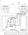
- FIG. 1 is a block diagram showing the configuration of a monitoring control system according to Embodiment 1;
- FIG. FIG. 2 is a diagram showing an example of a normal signal flow in the monitoring and control system according to Embodiment 1;
- FIG. 4 is a diagram showing an example of signal flow when an abnormality occurs in the monitoring and control system according to Embodiment 1;
- 2 is a block diagram showing the configuration of a monitoring control system according to Embodiment 2;
- FIG. FIG. 12 is a block diagram showing the configuration of a monitoring control system according to Embodiment 3;
- FIG. 1 is a hardware configuration diagram of a safety system and a normal system according to Embodiments 1 to 4;
- FIG. 1 is a block diagram showing the configuration of a supervisory control system according to Embodiment 1.
- a supervisory control system 100 includes a safety system 10 and a normal system 20 .
- the supervisory control system 100 has a function of detecting the abnormality in the safety system when an abnormality occurs in the normal system and not accepting signals from the abnormal device, thereby improving the safety of the system. is building.
- the safety system 10 is composed of a safety HMI system 1 and a safety DCS 3.
- the normal system 20 is composed of a normal HMI system 2 and a normal DCS 4 .
- a nuclear power plant is equipped with a reactor control device and a safety protection device for the nuclear reactor, and the normal system 20 includes both the reactor control device and the safety protection device for safety protection. Monitoring and Controlling, the safety system 10 monitors and controls the security devices.
- a safety protection device that protects the safety of a nuclear reactor is a device that operates to safely protect the nuclear reactor when an abnormality occurs in the nuclear power plant, and is equipped with various safety protection devices.
- the safety-related HMI system 1 is equipped with an on-operation switch 11 and an off-operation switch 12 for operating the safety protection device 200. By operating these switches 11 and 12, a safety system is operated via the safety system DCS 3. An operation signal is output to the protective device 200 .
- the normal HMI system 2 is equipped with a switch (not shown) for operating the reactor control device 300 and an ON operation switch 21 and an OFF operation switch 22 for operating the safety protection device 200 .
- a switch not shown
- an operation signal is output to the safety protection device 200 via the safety system DCS3
- an operation signal is output to the reactor control device 300 via the normal system DCS4 by a switch (not shown). is output.
- the monitoring and control of the reactor control system will be omitted.
- a coincidence determination circuit 31 , an AND circuit (logical product circuit) 32 , a parameter generating circuit 33 and an OR circuit (logical sum circuit) 34 are mounted on the safety system DCS 3 .
- the safety system DCS 3 the parameters generated by the parameter generation circuit 33 are transmitted to the regular HMI system 2 .
- the regular HMI system 2 the parameters received from the parameter generation circuit 33 of the safety DCS 3 are returned to the safety DCS 3.
- a coincidence determination circuit 31 receives the parameter generated by the parameter generation circuit 33 and the parameter returned from the normal HMI system 2, and outputs an ON signal to the AND circuit 32 when the two match. Output.
- the AND circuit 32 receives the operation signal of the common HMI system 2, that is, either the ON signal from the ON operation switch 21 or the OFF signal from the OFF operation switch 22, and the output signal from the match determination circuit 31. and outputs an ON signal to the OR circuit 34 only when both are ON.
- the output signal from the AND circuit 32 and the operation signal of the safety HMI system 1, that is, either the ON signal from the ON operation switch 11 or the OFF signal from the OFF operation switch 12 are input to the OR circuit 34 . If one of the signals input to the OR circuit 34 is ON, an operation signal is output to the safety protection device 200 .
- the signal from the parameter generation circuit 33 of the safety system DCS 3 cannot be returned, or an abnormal signal is returned.
- the parameter generated by the parameter generation circuit 33 input to the coincidence determination circuit 31 and the parameter returned from the common HMI system 2 do not match, and the AND circuit 32 outputs from the safety HMI system 1. Automatically blocks control signals.
- FIG. 2 shows an example of signal flow when the normal system 20 in FIG. 1 is normal.
- the parameter P1 generated by the parameter generation circuit 33 is returned to the coincidence determination circuit 31 , and the coincidence determination circuit 31 outputs an ON signal to the AND circuit 32 .
- the operation signal of the regular HMI system 2 is an ON signal
- the ON signal is output to the OR circuit 34
- the safety system DCS 3 outputs an operation signal to the local device related to safety.
- the operation signal of the normal HMI system 2 is an OFF signal
- no ON signal is output to the OR circuit 34
- the operation signal of the safety HMI system 1 is ON
- the safety protection device 200 An operation signal is output to .
- FIG. 3 shows an example of signal flow when an abnormality occurs in the normal system 20 in FIG.
- the parameter P1 generated by the parameter generation circuit 33 may or may not be returned as the parameter P2 to the coincidence determination circuit 31 when an abnormality occurs in the normal system 20 . Therefore, match determination circuit 31 does not output an ON signal to AND circuit 32 .
- the ON signal is not output from the AND circuit 32 to the OR circuit 34 regardless of whether the operation signal of the regular HMI system 2 is an ON signal or an OFF signal. That is, the operation signal from the regular HMI system 2 is blocked.
- the operation signal from the safety-related HMI system 1 is an ON signal
- the operation signal is output from the OR circuit 34 to the local device related to safety
- the operation signal from the safety-related HMI system 1 is an OFF signal
- No operation signal is output from the OR circuit 34 to the safety protection device 200 .
- the operation signal from the regular HMI system 2 is blocked, there is no fear of malfunctioning the local device related to safety.
- the operation signal from the safety HMI system 1 is turned on by the ON operation switch 11, the operation signal is output from the OR circuit 34, so that the safety protection device 200 can be continuously operated.
- the normal HMI system 2 is abnormal, it is preferable to block the operation signal from the normal HMI system 2 so that it is not output to the reactor control device 300 via the normal DCS 4 .
- the AND circuit 32 may block the operation signal from the normal HMI system 2 to the reactor control device 300, as indicated by the dashed arrow in FIG.
- the monitoring control system 100 does not simply stop transmission and reception of signals. Since the operation signal from the regular HMI system 2 is blocked when an abnormality occurs in the regular system, there is no risk of the safety protection device 200 malfunctioning. Furthermore, when the operation signal from the safety HMI system 1 is turned on by the ON operation switch 11, the operation signal is output from the OR circuit 34, so that the safety protection device 200 can be continuously operated. This is intended to improve the safety of a supervisory control system configured with such a dual system.
- the safety system 10 automatically blocks the output signal from the normal system 20 when there is an abnormality in the normal system 20, so that the safety of the monitoring control system 100 is improved. becomes possible.
- parameters are transmitted from the safety system DCS 3 to the normal system 20 to be transmitted to the safety system DCS 3, and the normal system HMI system 2 of the received normal system 20 returns a signal to the safety system DCS 3. , to confirm the soundness of the regular HMI system 2 .
- the safety system DCS 3 does not permit the signal from the normal system DCS 4, thereby preventing unnecessary operation of the safety function due to an erroneous signal from the normal system 20.
- the operation signal from the safety HMI system 1 is turned on by the ON operation switch 11, the operation signal is output from the OR circuit 34, so that the safety protection device 200 can be continuously operated.
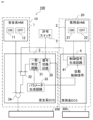
- FIG. 4 is a block diagram showing the configuration of a monitoring control system according to Embodiment 2.
- the safety system DCS 3 is provided with a signal switching circuit 35, and the signal input to the coincidence determination circuit 31 is provided outside the safety system 10 with the parameter returned from the normal HMI system 2.
- the reason for this is that the signal from the permission switch 5 is used for switching.
- Other configurations are the same as those of the first embodiment.
- the parameters generated by the parameter generation circuit 33 are transmitted to the regular HMI system 2 in the safety system DCS 3 .
- the parameters received from the parameter generation circuit 33 of the safety DCS 3 are returned to the safety DCS 3.
- the parameters returned from the regular HMI system 2 are input to the coincidence determination circuit 31 via the signal switching circuit 35 in the safety DCS 3 .
- the signal switching circuit 35 When the permission signal is input from the permission switch 5, the signal switching circuit 35 outputs the parameters returned from the common HMI system 2 as they are. On the other hand, when the permission signal is not input from the permission switch 5, a signal different from the parameter generated by the parameter generation circuit 33 is output.
- a coincidence determination circuit 31 receives a parameter generated by a parameter generation circuit 33 and a signal output from a signal switching circuit 35, and outputs an ON signal to an AND circuit 32 when both match. do.
- the following operations are the same as those of the first embodiment.
- the permission switch 5 can be operated so as not to output the permission signal, thereby ensuring the soundness of the system.
- the safety system DCS 3 can be prevented from permitting the signal from the normal system DCS 4 when an abnormality of the normal system 20 is detected. can be increased.
- FIG. 5 is a block diagram showing the configuration of a supervisory control system according to the third embodiment.
- the difference from the second embodiment is that the normal DCS 4 is provided with a control signal generation circuit 41 and the parameters generated by the parameter generation circuit 33 of the safety DCS 3 are transmitted to the normal DCS 4 .
- Other configurations are the same as those of the second embodiment.
- the regular HMI system 2 is equipped with an ON operation switch 21 and an OFF operation switch 22 for operating the safety protection device 200 of the facility to be monitored.
- an operation signal is output to the safety protection device 200 via the normal DCS 4 .
- an operation signal is transmitted to the safety system DCS3 via the normal system DCS4.
- a control signal generation circuit 41 mounted on the normal DCS 4 receives an operation signal from the normal HMI system 2 and an automatic control signal. It will be sent to DCS3.
- the parameters generated by the parameter generation circuit 33 are transmitted to the normal system DCS4.
- the regular DCS 4 returns the parameters received from the parameter generation circuit 33 of the safety DCS 3 to the safety DCS 3 .
- the parameters returned from the normal DCS 4 are input to the coincidence determination circuit 31 via the signal switching circuit 35 in the safety DCS 3 .
- the signal switching circuit 35 When the permission signal is input from the permission switch 5, the signal switching circuit 35 outputs the parameter returned from the regular DCS 4 as it is. On the other hand, when the permission signal is not input from the permission switch 5, a signal different from the parameter generated by the parameter generation circuit 33 is output. That is, as in the second embodiment, signal switching circuit 35 switches the signal to be input to coincidence determination circuit 31 according to the signal from permission switch 5 .
- the operation signal from the normal-use HMI system 2 is input to the safety-system DCS3 via the normal-use DCS4, in addition to the operation signal from the normal-use HMI system 2, the operation signal from the normal-use DCS4 to the safety-system DCS3
- the automatic control signal of is also subject to determination by the match determination circuit 31. This makes it possible to confirm the soundness of the regular HMI system 2 and the regular DCS 4 .
- the same effects as those of the first and second embodiments are obtained. Furthermore, by confirming the soundness of both the regular HMI system 2 and the regular DCS 4, the safety of the monitoring control system 100 can be further enhanced.
- Embodiment 4 Although the transmission of the parameters generated by the parameter generation circuit 33 has been described in the first to third embodiments, the parameters generated by the parameter generation circuit 33 may be changed at regular time intervals. In the event of an abnormal state in which the return signal from the normal HMI system 2 or the signal output from the normal DCS 4 is stuck, if the parameters are changed at regular intervals, the changed parameters will be applied to the normal HMI system. 2 or whether or not the regular DCS 4 can cope with the abnormal condition. That is, in the case of an abnormal state as described above, the coincidence determination circuit 31 becomes inconsistent and the abnormality can be detected.
- the safety system 10 and the normal system 20 of the supervisory control system 100 are composed of a processor 101 and a storage device 102, as shown in FIG. 6 as an example of hardware.
- the storage device includes a volatile storage device such as a random access memory and a non-volatile auxiliary storage device such as a flash memory.
- an auxiliary storage device such as a hard disk may be provided instead of the flash memory.
- Processor 101 executes a program input from storage device 102 . In this case, the program is input from the auxiliary storage device to the processor 101 via the volatile storage device. Further, the processor 101 may output data such as calculation results to the volatile storage device of the storage device 102, or may store the data in an auxiliary storage device via the volatile storage device.
- the normal system 20 monitors and controls the control device of the plant and the safety protection device of the plant
- the safety system 10 monitors and controls the plant monitoring and control of safety protection devices. That is, an example of a plant is a nuclear power plant, and the most suitable example of the monitoring and control target of the present disclosure is the nuclear power plant.
- Safety HMI system 1: Safety HMI system
- 2: Regular HMI system 3: Safety DCS
- 10: Safety system 20: Regular system, 11, 21: ON operation switch , 12, 22: OFF operation switch, 31: coincidence determination circuit
- 41: control signal generation circuit 100: monitoring control system, 101: processor, 102: storage device, 200: safety protection device, 300: reactor control device.
Landscapes
- Engineering & Computer Science (AREA)
- Physics & Mathematics (AREA)
- General Engineering & Computer Science (AREA)
- Plasma & Fusion (AREA)
- High Energy & Nuclear Physics (AREA)
- General Physics & Mathematics (AREA)
- Automation & Control Theory (AREA)
- Business, Economics & Management (AREA)
- Emergency Management (AREA)
- Safety Devices In Control Systems (AREA)
- Monitoring And Testing Of Nuclear Reactors (AREA)
Priority Applications (5)
| Application Number | Priority Date | Filing Date | Title |
|---|---|---|---|
| EP22923726.8A EP4471804A4 (en) | 2022-01-25 | 2022-01-25 | MONITORING AND CONTROL SYSTEM |
| CA3239225A CA3239225A1 (en) | 2022-01-25 | 2022-01-25 | Monitoring and controlling system |
| JP2023576260A JP7527509B2 (ja) | 2022-01-25 | 2022-01-25 | 監視制御システム |
| US18/711,398 US20250022623A1 (en) | 2022-01-25 | 2022-01-25 | Monitoring and controlling system |
| PCT/JP2022/002513 WO2023144857A1 (ja) | 2022-01-25 | 2022-01-25 | 監視制御システム |
Applications Claiming Priority (1)
| Application Number | Priority Date | Filing Date | Title |
|---|---|---|---|
| PCT/JP2022/002513 WO2023144857A1 (ja) | 2022-01-25 | 2022-01-25 | 監視制御システム |
Publications (1)
| Publication Number | Publication Date |
|---|---|
| WO2023144857A1 true WO2023144857A1 (ja) | 2023-08-03 |
Family
ID=87471099
Family Applications (1)
| Application Number | Title | Priority Date | Filing Date |
|---|---|---|---|
| PCT/JP2022/002513 Ceased WO2023144857A1 (ja) | 2022-01-25 | 2022-01-25 | 監視制御システム |
Country Status (5)
| Country | Link |
|---|---|
| US (1) | US20250022623A1 (https=) |
| EP (1) | EP4471804A4 (https=) |
| JP (1) | JP7527509B2 (https=) |
| CA (1) | CA3239225A1 (https=) |
| WO (1) | WO2023144857A1 (https=) |
Citations (4)
| Publication number | Priority date | Publication date | Assignee | Title |
|---|---|---|---|---|
| JPS61290836A (ja) | 1985-06-19 | 1986-12-20 | Nissin Electric Co Ltd | デ−タ伝送制御方式 |
| JP2012083231A (ja) | 2010-10-12 | 2012-04-26 | Mitsubishi Heavy Ind Ltd | 原子力施設の制御システム |
| JP2012103013A (ja) * | 2010-11-05 | 2012-05-31 | Mitsubishi Heavy Ind Ltd | 原子力プラントの運転監視装置 |
| JP2017201461A (ja) * | 2016-05-02 | 2017-11-09 | 株式会社東芝 | 出入監視システム及び出入監視方法 |
Family Cites Families (3)
| Publication number | Priority date | Publication date | Assignee | Title |
|---|---|---|---|---|
| JP5422448B2 (ja) * | 2010-03-10 | 2014-02-19 | 株式会社東芝 | 制御装置 |
| KR102873531B1 (ko) * | 2016-12-30 | 2025-10-17 | 뉴스케일 파워, 엘엘씨 | 핵 반응기 보호 시스템 및 방법 |
| JP6822992B2 (ja) * | 2018-02-28 | 2021-01-27 | 日立Geニュークリア・エナジー株式会社 | 中央制御室外原子炉停止システム |
-
2022
- 2022-01-25 EP EP22923726.8A patent/EP4471804A4/en active Pending
- 2022-01-25 JP JP2023576260A patent/JP7527509B2/ja active Active
- 2022-01-25 CA CA3239225A patent/CA3239225A1/en active Pending
- 2022-01-25 WO PCT/JP2022/002513 patent/WO2023144857A1/ja not_active Ceased
- 2022-01-25 US US18/711,398 patent/US20250022623A1/en active Pending
Patent Citations (4)
| Publication number | Priority date | Publication date | Assignee | Title |
|---|---|---|---|---|
| JPS61290836A (ja) | 1985-06-19 | 1986-12-20 | Nissin Electric Co Ltd | デ−タ伝送制御方式 |
| JP2012083231A (ja) | 2010-10-12 | 2012-04-26 | Mitsubishi Heavy Ind Ltd | 原子力施設の制御システム |
| JP2012103013A (ja) * | 2010-11-05 | 2012-05-31 | Mitsubishi Heavy Ind Ltd | 原子力プラントの運転監視装置 |
| JP2017201461A (ja) * | 2016-05-02 | 2017-11-09 | 株式会社東芝 | 出入監視システム及び出入監視方法 |
Non-Patent Citations (1)
| Title |
|---|
| See also references of EP4471804A4 |
Also Published As
| Publication number | Publication date |
|---|---|
| EP4471804A1 (en) | 2024-12-04 |
| JP7527509B2 (ja) | 2024-08-02 |
| US20250022623A1 (en) | 2025-01-16 |
| JPWO2023144857A1 (https=) | 2023-08-03 |
| CA3239225A1 (en) | 2023-08-03 |
| EP4471804A4 (en) | 2025-04-09 |
Similar Documents
| Publication | Publication Date | Title |
|---|---|---|
| EP0109602B1 (en) | Fault tolerable redundancy control | |
| US9997265B2 (en) | Safety system for a nuclear power plant and method for operating the same | |
| US5920715A (en) | System architecture permitting verified and unverified programs to execute safely on one processor | |
| WO2014054349A1 (ja) | 冗長化演算処理システム | |
| KR101831398B1 (ko) | 다양성보호계통시스템 | |
| WO2023144857A1 (ja) | 監視制御システム | |
| KR880002046B1 (ko) | 논리 안전 시스템 | |
| US10109440B2 (en) | Safety switch | |
| US12451262B2 (en) | Control switching device | |
| CN113299419B (zh) | 核电厂操纵员控制盘台的切换方法、装置、设备及介质 | |
| US11609999B2 (en) | Control system | |
| CN117794679A (zh) | 用于激光功率监测的装置和方法 | |
| US20250155887A1 (en) | Safety protection system backup device | |
| JP7357829B1 (ja) | プラントの制御システム | |
| EP1290794B1 (en) | Security system | |
| US20230365380A1 (en) | Brake System for Use in Shaft and Inclined Conveyor Systems | |
| JP5190032B2 (ja) | 遮断器用操作器 | |
| JP5767922B2 (ja) | ディジタル型保護継電システム | |
| JP2988476B2 (ja) | 原子炉保護装置 | |
| WO2023100275A1 (ja) | 安全保護装置 | |
| JP2956700B2 (ja) | 原子炉保護装置 | |
| JPH01279301A (ja) | 計算機分散システム | |
| JPH11305801A (ja) | プロセス制御装置 | |
| JPS60196831A (ja) | 異常温度検出装置 | |
| JP2019028014A (ja) | 制御棒操作監視システム |
Legal Events
| Date | Code | Title | Description |
|---|---|---|---|
| 121 | Ep: the epo has been informed by wipo that ep was designated in this application |
Ref document number: 22923726 Country of ref document: EP Kind code of ref document: A1 |
|
| WWE | Wipo information: entry into national phase |
Ref document number: 18711398 Country of ref document: US |
|
| ENP | Entry into the national phase |
Ref document number: 3239225 Country of ref document: CA |
|
| ENP | Entry into the national phase |
Ref document number: 2023576260 Country of ref document: JP Kind code of ref document: A |
|
| NENP | Non-entry into the national phase |
Ref country code: DE |
|
| ENP | Entry into the national phase |
Ref document number: 2022923726 Country of ref document: EP Effective date: 20240826 |