WO2023136181A1 - 電力変換装置、コンデンサ装置、制御方法およびコンピュータプログラム - Google Patents
電力変換装置、コンデンサ装置、制御方法およびコンピュータプログラム Download PDFInfo
- Publication number
- WO2023136181A1 WO2023136181A1 PCT/JP2022/048641 JP2022048641W WO2023136181A1 WO 2023136181 A1 WO2023136181 A1 WO 2023136181A1 JP 2022048641 W JP2022048641 W JP 2022048641W WO 2023136181 A1 WO2023136181 A1 WO 2023136181A1
- Authority
- WO
- WIPO (PCT)
- Prior art keywords
- capacitor elements
- circuit
- voltage
- capacitor
- switching
- Prior art date
- Legal status (The legal status is an assumption and is not a legal conclusion. Google has not performed a legal analysis and makes no representation as to the accuracy of the status listed.)
- Ceased
Links
Images


Classifications
-
- H—ELECTRICITY
- H02—GENERATION; CONVERSION OR DISTRIBUTION OF ELECTRIC POWER
- H02M—APPARATUS FOR CONVERSION BETWEEN AC AND AC, BETWEEN AC AND DC, OR BETWEEN DC AND DC, AND FOR USE WITH MAINS OR SIMILAR POWER SUPPLY SYSTEMS; CONVERSION OF DC OR AC INPUT POWER INTO SURGE OUTPUT POWER; CONTROL OR REGULATION THEREOF
- H02M7/00—Conversion of AC power input into DC power output; Conversion of DC power input into AC power output
- H02M7/42—Conversion of DC power input into AC power output without possibility of reversal
- H02M7/44—Conversion of DC power input into AC power output without possibility of reversal by static converters
- H02M7/48—Conversion of DC power input into AC power output without possibility of reversal by static converters using discharge tubes with control electrode or semiconductor devices with control electrode
Definitions
- the present disclosure relates to power conversion devices, capacitor devices, control methods, and computer programs.
- Patent Document 1 based on the voltage detection means for detecting the voltage between the terminals of the capacitor of the LC smoothing circuit, the filter means for extracting the vibration component from the detected voltage between the terminals, and the extracted vibration component, A control device for a power conversion device is disclosed, which is characterized by comprising switching frequency varying means for varying the switching frequency of the inverter.
- the control device can detect and suppress LC resonance generated by the inductance component and the capacitance component.
- the technique disclosed in Patent Document 1 cannot detect LC resonance that may occur between the capacitor elements when the capacitor is configured by connecting a plurality of capacitor elements in parallel. As a result, LC resonance occurs between the capacitor elements and an excessive current flows through the capacitor elements, causing a temperature rise due to heat generation, overheating or burning of the capacitor, destabilization of the output of the device, or stoppage of the function of the device. could have occurred.
- An object of the present disclosure is to provide a power conversion device, a capacitor device, a control method, and a computer program that can detect the occurrence of LC resonance between capacitor elements connected in parallel to a DC power supply.
- a power conversion device includes a plurality of switching elements connected to a DC power supply, and a DC voltage supplied from the DC power supply by performing a switching process of switching the plurality of switching elements at a predetermined switching frequency. is converted into a predetermined output voltage and output to the load, and a plurality of capacitor elements are connected in parallel to the DC power supply.
- a smoothing circuit that smoothes by using a voltage measuring device that measures the voltage across each of the plurality of capacitor elements; , wherein the determination process obtains the effective value of the AC component of the voltage across each of the plurality of capacitor elements based on the voltage across each of the plurality of capacitor elements measured by the voltage measurement device when the switching process is executed, When the evaluation value based on the maximum value of the values exceeds a predetermined threshold, it is determined that the currents flowing through the plurality of capacitor elements are unbalanced.
- a capacitor device includes a plurality of switching elements connected to a DC power supply, and performs a switching process of switching the plurality of switching elements at a predetermined switching frequency to convert a DC voltage supplied from the DC power supply. It has a conversion circuit that converts to a predetermined output voltage and outputs it to the load, and a plurality of capacitor elements connected in parallel to the DC power supply, and the pulsation generated during conversion in the conversion circuit is
- a capacitor device used in a power conversion device comprising a smoothing circuit for smoothing, the capacitor device having a plurality of capacitor elements and a housing mounted with the plurality of capacitor elements, each of the plurality of capacitor elements , and has terminals capable of detecting voltages across a plurality of capacitor elements and available from the outside of the capacitor device.
- a control method has a plurality of switching elements connected to a DC power supply, and performs a switching process of switching the plurality of switching elements at a predetermined switching frequency to convert a DC voltage supplied from the DC power supply. It has a conversion circuit that converts to a predetermined output voltage and outputs it to the load, and a plurality of capacitor elements connected in parallel to the DC power supply, and the pulsation generated during conversion in the conversion circuit is
- a control method for determining an imbalance of currents flowing through a plurality of capacitor elements in a power conversion device having a smoothing circuit for smoothing and a voltage measuring device for measuring voltages across a plurality of capacitor elements the control method comprising: switching Acquire the effective value of the AC component of the voltage across each of the plurality of capacitor elements based on the voltage across each of the plurality of capacitor elements measured by the voltage measurement device during execution of the process, and evaluate based on the maximum value among the effective values When the value exceeds a predetermined threshold, it is determined that an imbalance of currents
- a computer program according to the present disclosure is a computer program for causing an arithmetic circuit to execute the control method according to the present disclosure.
- a power conversion device a capacitor device, a control method, and a computer program that can detect the occurrence of LC resonance between capacitor elements connected in parallel to a DC power supply.
- FIG. 4 is a perspective view of an example of a capacitor device that can be used in a smoothing circuit of a power conversion device according to another embodiment
- FIG. 11B is a bottom perspective view of the capacitor device of FIG. 11A
- FIG. 4 is a perspective view of an example of a capacitor device that can be used in a smoothing circuit of a power conversion device according to another embodiment
- FIG. 12B is a perspective view of the capacitor device shown in FIG. 12A with a portion of the housing removed;
- FIG. 1 is a schematic circuit diagram of a configuration example of a power converter 1 according to an embodiment of the present disclosure.
- the power conversion device 1 includes a smoothing circuit 20 , a voltage measurement device 30 , a conversion circuit 40 and a control device 60 .
- the control device 60 includes an arithmetic circuit 61 and a storage device 62 .
- the smoothing circuit 20 has a plurality of capacitor elements 21 connected in parallel to the DC power supply 10 (details will be described later).
- the smoothing circuit 20 uses a plurality of capacitor elements 21 to smooth pulsation generated when the voltage is converted by the conversion circuit 40 .
- the conversion circuit 40 has a plurality of switching elements 42 and 43 connected to the smoothing circuit 20 (details will be described later). Conversion circuit 40 converts the DC voltage supplied from DC power supply 10 into a predetermined output voltage by executing a switching process of switching a plurality of switching elements 42 and 43 at a predetermined switching frequency, and outputs the output voltage to load 50 . .
- the voltage measuring device 30 measures the voltage across each of the plurality of capacitor elements.
- the arithmetic circuit 61 executes determination processing to determine whether an imbalance of currents flowing through the plurality of capacitor elements 21 has occurred. Arithmetic circuit 61 calculates the effective value of the AC component of the voltage across each of the plurality of capacitor elements 21 based on the voltage across each of the plurality of capacitor elements 21 measured by the voltage measuring device 30 during execution of the switching process. get. Then, if the evaluation value based on the maximum value among the effective values exceeds a predetermined threshold, the arithmetic circuit 61 determines that an imbalance of currents flowing through the plurality of capacitor elements 21 has occurred.
- the power converter 1 can detect the occurrence of LC resonance that can occur in the plurality of capacitor elements 21 of the smoothing circuit 20 .
- the power conversion device 1 according to the present disclosure does not need to identify in advance a frequency at which LC resonance can occur and include a filter for extracting LC resonance at that frequency. Therefore, the power conversion device 1 according to the present disclosure can detect the occurrence of LC resonance even if unexpected and accidental LC resonance occurs and the LC resonance is at an unexpected frequency.
- the power converter 1 can change the frequency of switching performed in the switching process so as to reduce the current imbalance caused by the LC resonance.
- the power conversion device 1 can reduce the output voltage output from the conversion circuit 40 to the load 50 so as to reduce the current imbalance caused by the LC resonance.
- the power converter 1 converts a DC voltage from a DC power supply 10 into a predetermined voltage and outputs the voltage to a motor 50 as a load.
- the power conversion device 1 includes the smoothing circuit 20, the voltage measurement device 30, the conversion circuit 40, and the control device 60.
- the power conversion device 1 is used, for example, in a motor-driving inverter device mounted on an electric vehicle.
- the DC power supply 10 is a power supply device that applies a DC voltage across the smoothing circuit 20 and the conversion circuit 40 . Thereby, the DC power supply 10 supplies current for driving the motor 50 to the conversion circuit 40 .
- DC power supply 10 may be charged by regenerated current from motor 50 as described later.
- the DC power supply 10 may be, for example, a battery that supplies DC current.
- the DC power supply 10 may be a power supply device including an AC power supply and an AC-DC converter that converts an AC voltage into a DC voltage and supplies the DC voltage to the conversion circuit 40 .
- FIG. 2 is a schematic circuit diagram of a configuration example of the smoothing circuit 20 according to this embodiment.
- smoothing circuit 20 includes a plurality of capacitor elements 21 connected in parallel to DC power supply 10 .
- Smoothing circuit 20 according to the present embodiment includes four capacitor elements 21a to 21d.
- the number of capacitor elements 21 is not limited to four, and may be any number equal to or greater than two.
- the smoothing circuit 20 can smooth such pulsating components generated by the conversion in the conversion circuit 40 by the plurality of capacitor elements 21a to 21d. In addition, the smoothing circuit 20 can smooth and suppress noise generated in the DC voltage due to a steep current flowing when the current is supplied from the DC power supply 10 to the motor 50 . If the DC voltage applied by the DC power supply 10 has a pulsating current component, the smoothing circuit 20 can smooth the pulsating current component. In addition, the smoothing circuit 20 can smooth pulsating current components generated in the DC voltage by the regenerative current generated by the rotation of the motor 50 when the regenerative current flows.
- the voltage measuring device 30 is configured to measure the voltage across each of the capacitor elements 21a to 21d.
- the voltage measuring device 30 has voltmeters 31a to 31d as described later (see FIG. 2).
- the voltage measuring device 30 outputs to the control device 60 voltage information indicating voltages respectively measured by the voltmeters 31a to 31d.
- the conversion circuit 40 converts the DC voltage supplied from the DC power supply 10 into a predetermined output voltage and outputs it to the motor 50 as a load.
- the predetermined output voltage is, for example, a three-phase AC voltage.
- the conversion circuit 40 is, for example, an inverter that converts a DC current supplied from the DC power supply 10 into a three-phase AC current and transmits the three-phase AC current to the motor 50 .
- the conversion circuit 40 may be capable of converting an alternating current into a direct current when a regenerated current generated by the rotation of the motor 50 flows.
- the conversion circuit 40 has two or more legs connected in parallel across the DC power supply 10 and the smoothing circuit 20 .
- conversion circuit 40 includes three legs 41A, 41B, 41C.
- Leg 41A has a pair of switches, upstream switch 42A and downstream switch 43A, connected in series.
- Leg 41B has a pair of switches, upstream switch 42B and downstream switch 43B, connected in series.
- Leg 41C has a pair of switches, upstream switch 42C and downstream switch 43C, connected in series.
- the leg 41A is connected to the motor 50 via a resistor 44A at a connection point between the upstream switch 42A and the downstream switch 43A.
- the leg 41B is connected to the motor 50 via a resistor 44B at a connection point between the upstream switch 42B and the downstream switch 43B.
- the leg 41C is connected to the motor 50 via a resistor 44C at a connection point between the upstream switch 42C and the downstream switch 43C.
- the arithmetic circuit 61 can control on/off of the six switches 42A to 42C and 43A to 43C. Thereby, the arithmetic circuit 61 can convert the DC voltage supplied from the DC power supply 10 into an AC voltage and supply it to the motor 50 . For example, the arithmetic circuit 61 alternately turns on and off the upstream side switches 42A to 42C and the downstream side switches 43A to 43C in each leg 41A, 41B, 41C at predetermined positions in the three legs 41A, 41B, 41C.
- a three-phase AC voltage is supplied to the motor 50 by providing a phase difference (for example, 120 degrees).
- Each of the switches 42A to 42C and 43A to 43C may be composed of a transistor and a diode, for example.
- conversion circuit 40 has a plurality of switching elements 42 and 43 connected to DC power supply 10 and smoothing circuit 20 . Then, the conversion circuit 40 converts the DC voltage supplied from the DC power supply 10 to a predetermined output voltage by performing a switching process in which the arithmetic circuit 61 switches the plurality of switching elements 42 and 43 at a predetermined switching frequency. It converts and outputs to the motor 50 .
- the motor 50 is, for example, a load circuit that rotates any component based on current supplied from the DC power supply 10 via the conversion circuit 40 .
- the load circuit is not limited to a circuit such as a rotary motor that rotates a component, but may be a linear motor that directs a component or any load circuit that uses alternating current.
- the motor 50 may generate a regenerated current by being rotated by an external force when no current is supplied, and supply the regenerated current to the DC power supply 10 via the conversion circuit 40 .
- the control device 60 is, for example, a computer that controls the operation of the power conversion device 1.
- the control device 60 has an arithmetic circuit 61 and a storage device 62 .
- the arithmetic circuit 61 includes a general-purpose processor such as a CPU or MPU that implements predetermined functions by executing programs.
- the arithmetic circuit 61 is configured to be able to communicate with the storage device 62 , and implements various processes in the control device 60 by calling and executing an arithmetic program or the like stored in the storage device 62 .
- the arithmetic circuit 61 can realize a switching process for switching ON/OFF of the switches 42A to 42C and 43A to 43C, a determination process to be described later, and the like.
- Arithmetic circuit 61 is not limited to a form in which hardware resources and software work together to achieve a predetermined function, and may be a hardware circuit specifically designed to achieve a predetermined function.
- the arithmetic circuit 61 can be realized by various processors such as GPU, FPGA, DSP, ASIC, etc., in addition to CPU and MPU.
- Such an arithmetic circuit 61 can be configured by, for example, a signal processing circuit that is a semiconductor integrated circuit.
- the storage device 62 is a storage medium that can store various information.
- the storage device 62 can store voltage information from the voltage measuring device 30, and the arithmetic circuit 61 can use the stored voltage information.
- the storage device 62 is realized by, for example, memories such as DRAM, SRAM, flash memory, HDD, SSD, other storage devices, or an appropriate combination thereof.
- the storage device 62 stores programs for realizing various processes performed by the control device 60 by the arithmetic circuit 61, as described above.
- the storage device 62 may store arbitrary parameters such as a capacitance component, a resistance component, and an inductance component of the smoothing circuit 20, which will be described later.
- smoothing circuit 20 includes four capacitor elements 21a-21d. As shown in FIG. 2, the four capacitor elements 21a-21d form a parallel circuit. The parallel circuit is connected to the DC power supply 10 via a connection point 23a on the first end side of the four capacitor elements 21a to 21d and a connection point 23b on the second end side of the four capacitor elements 21a to 21d. connected in parallel.
- each of the capacitor elements 21a to 21d of the smoothing circuit 20 has capacitance Ca to Cd [ ⁇ F], resistance components Ra to Rd [m ⁇ ] due to equivalent series resistance, and inductance components La1 to Ld1 [nH] due to equivalent series inductance, respectively. 1 and 2, the smoothing circuit 20 has a first end 22a connected to the positive pole of the DC power supply 10 and a second end 22b connected to the negative pole. Each capacitor element 21a-21d is positioned between a first end 22a and a second end 22b. In the present embodiment, smoothing circuit 20 is configured such that capacitor elements 21a to 21d are connected to first end 22a and second end 22b by connection point 23a and connection point 23b.
- the smoothing circuit 20 has inductance components La2 to Ld2 [nH] formed by circuits between the connection points 23a and 23b excluding the capacitor elements 21a to 21d for the paths of the capacitor elements 21a to 21d.
- the smoothing circuit 20 also has an inductance component L3 formed by a circuit between the first end 22a and the connection point 23a and a circuit between the second end 22b and the connection point 23b. More specifically, the inductance component L3 represents an inductance component in a state where the first end 22a is connected to the positive pole of the DC power supply 10 and the second end 22b is connected to the negative pole of the DC power supply 10.
- the circuits associated with each of the capacitor elements 21a-21d included in the smoothing circuit 20 (herein also referred to as paths of each capacitor element 21a-21d) have different impedance values.
- the path of the capacitor element 21a means a circuit from the connection point 23a through the capacitor element 21a to the connection point 23b.
- the smoothing circuit 20 can smooth the pulsation generated by the conversion in the conversion circuit 40 using the plurality of capacitor elements 21a to 21d. can. Also, the smoothing circuit 20 is charged with the DC voltage supplied from the DC power supply 10 as described above. Furthermore, the smoothing circuit 20 supplies current to the conversion circuit 40 . At this time, a current flows through the smoothing circuit 20 . Since the smoothing circuit 20 has a plurality of capacitor elements 21a to 21d, the current is divided and flows through the plurality of capacitor elements 21a to 21d. The ratio of current sharing among the plurality of capacitor elements 21a to 21d is determined by the impedance values described above.
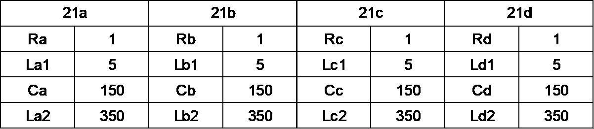
- the smoothing circuit 20 of circuit example 1 has paths of capacitor elements 21a to 21d with parameters shown in Table 1 below.
- FIG. 3A is a graph showing frequency characteristics regarding impedance of the smoothing circuit 20 of Circuit Example 1.
- FIG. The impedance is the impedance between the first end 22a and the second end 22b.
- FIG. 3B relates to the magnitude of the current flowing through each of the capacitor elements 21a to 21d when a current having a constant effective value and an AC component with a predetermined frequency flows through the smoothing circuit 20 of Circuit Example 1.
- 4 is a graph showing frequency characteristics; FIG. 3B shows the frequency response for the frequency range from 10 kHz to 100 kHz.
- the predetermined frequency can be determined based on the switching frequency of switching processing executed by the arithmetic circuit 61 .
- the frequency of the AC component of the current flowing through each of the capacitor elements 21a to 21d is also called ripple frequency.
- the inductance value of the inductance component L3 is 50 nH.
- the smoothing circuit 20 of circuit example 1 is configured to have a resonance frequency near about 15 kHz.
- FIG. 3B when a current having a constant effective value is passed through the smoothing circuit 20 of the circuit example 1, the paths of the capacitor elements 21a to 21d have an equivalent current regardless of changes in the ripple frequency. A large amount of current flows. Therefore, when the paths of the capacitor elements 21a to 21d have the same impedance as in the smoothing circuit 20 in this example, the same current flows through each path and current imbalance does not occur. Therefore, the smoothing circuit 20 having the paths of the parameters shown in Table 1 does not have a parallel resonance frequency, which is a frequency at which LC resonance can occur between the paths of the capacitor elements 21a to 21d.
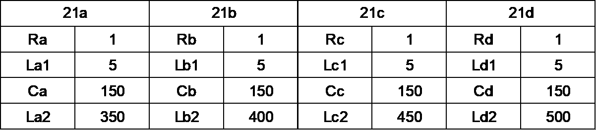
- the smoothing circuit 20 of circuit example 2 has paths of capacitor elements 21a to 21d with parameters shown in Table 2 below.
- FIG. 4A is a graph showing frequency characteristics regarding impedance of the smoothing circuit 20 of the circuit example 2.
- the impedance is the impedance between the first end 22a and the second end 22b.
- the parameters of the circuit example 2 are different from the parameters of the circuit example 1 only in the inductance values of the inductance components Lb2 to Ld2. That is, the parameters of the circuit example 2 are different from the parameters of the circuit example 1 in terms of the inductance values based on the paths of the capacitor elements 21b to 21d.
- 4B relates to the magnitude of the current flowing through each of the capacitor elements 21a to 21d when a current having a constant effective value and an AC component with a predetermined frequency flows through the smoothing circuit 20 of Circuit Example 2.
- 4 is a graph showing frequency characteristics; Note that the inductance value of the inductance component L3 is 50 nH.
- the smoothing circuit 20 of circuit example 2 is configured to have a resonance frequency near about 15 kHz.
- the frequency characteristic shown in FIG. 4A has a resonance point near about 20 kHz compared with the frequency characteristic shown in FIG. 3A.
- the resonance point corresponds to the parallel resonance frequency, which is the frequency at which LC resonance can occur.
- FIG. 4B when a current having a constant effective value is passed through the smoothing circuit 20 of the circuit example 2, different magnitudes are generated in the paths of the capacitor elements 21a to 21d based on the impedance of each path. current flows.
- the solid line indicates the magnitude of the current flowing through the path of the capacitor element 21a.
- FIG. 4B shows the magnitude of the current flowing through the path of capacitor element 21b with a dashed line.
- FIG. 4B shows the magnitude of the current flowing through the path of the capacitor element 21c with a thick solid line.
- FIG. 4B shows the magnitude of the current flowing through the path of the capacitor element 21d with a dashed line.
- the largest current flows through the path of the capacitor element 21 a when a current having an AC component with a ripple frequency higher than 20 kHz flows through the smoothing circuit 20 .
- the path of the capacitor element 21d carries the largest current when a current having an AC component with a ripple frequency lower than 20 kHz flows through the smoothing circuit 20 . Therefore, when the paths of the capacitor elements 21a to 21d have impedances of different values as in the smoothing circuit 20 of circuit example 2, a current flows through each path based on the impedance, and current imbalance occurs between the paths. occurs.
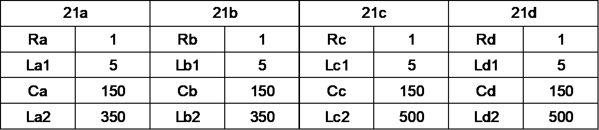
- the smoothing circuit 20 of circuit example 3 has paths of capacitor elements 21a to 21d with parameters shown in Table 3 below.
- FIG. 5A is a graph showing frequency characteristics regarding impedance of the smoothing circuit 20 of Circuit Example 3.
- FIG. The impedance is the impedance between the first end 22a and the second end 22b.
- the parameters of the circuit example 3 are different from the parameters of the circuit example 1 only in the inductance values of the inductance components Lc2 and Ld2. That is, the parameters of the circuit example 3 are different from the parameters of the circuit example 1 in terms of the inductance values based on the paths of the capacitor elements 21c and 21d.
- 5B relates to the magnitude of the current flowing through each of the capacitor elements 21a to 21d when a current having a constant effective value and an AC component with a predetermined frequency flows through the smoothing circuit 20 of Circuit Example 3.
- 4 is a graph showing frequency characteristics; Note that the inductance value of the inductance component L3 is 50 nH.
- the smoothing circuit 20 of circuit example 3 is configured to have a resonance frequency near about 15 kHz.
- the frequency characteristic shown in FIG. 5A has a resonance point near about 20 kHz compared to the frequency characteristic shown in FIG. 3A.
- the resonance point corresponds to the parallel resonance frequency, which is the frequency at which LC resonance can occur.
- FIG. 5B when a current having a constant effective value is passed through the smoothing circuit 20 of the circuit example 3, the paths of the capacitor elements 21a to 21d have different magnitudes based on the impedance of each path. current flows.
- the solid line indicates the magnitude of the current flowing through the path of the capacitor element 21a.
- FIG. 5B shows the magnitude of the current flowing through the path of the capacitor element 21c with a dashed line.
- the dashed-dotted line also indicates the magnitude of the current flowing through the path of the capacitor element 21d.
- each of the capacitor elements 21a-21d is maximized when a current having an AC component with a ripple frequency of about 20 kHz flows through the smoothing circuit 20 in the frequency range of 10 kHz-100 kHz. A large current flows.
- the path of each capacitor element 21a, 21b carries the smallest current when a current having an AC component with a ripple frequency lower than 20 kHz flows through the smoothing circuit 20.
- each capacitor element 21c, 21d carries the smallest current when a current having an AC component with a ripple frequency higher than 20 kHz flows through the smoothing circuit 20.
- FIG. Therefore, when the paths of the capacitor elements 21a and 21b and the paths of the capacitor elements 21c and 21d have different impedances as in the smoothing circuit 20 in this example, a current flows through each path based on the impedance, and the current flows between the paths. A current imbalance occurs at
- the power converter 1 can detect that the current imbalance has occurred. More specifically, the arithmetic circuit 61 of the control device 60 of the power conversion device 1 determines whether current imbalance has occurred based on the voltage across each of the capacitor elements 21a to 21d detected by the voltage measurement device 30. can judge. A process of determining whether or not current imbalance occurs by the arithmetic circuit 61 will be described below.
- FIG. 6 is a flowchart of determination processing executed by the arithmetic circuit 61 of the control device 60 included in the power converter 1 according to the present embodiment.
- the arithmetic circuit 61 acquires the effective value of the AC component of the voltage across each of the plurality of capacitor elements 21a to 21d ( S10).
- the arithmetic circuit 61 can store each acquired effective value in the storage device 62, for example.
- the arithmetic circuit 61 can store the effective value in the storage device 62 in association with the switching frequency of the switching process when the effective value is acquired.
- the arithmetic circuit 61 may associate the effective value with the ripple frequency and store them in the storage device 62 .
- the arithmetic circuit 61 calculates an evaluation value based on the maximum value among the acquired effective values (S11). For example, the arithmetic circuit 61 determines the maximum value of the acquired effective values and the minimum value of the acquired effective values, calculates the difference between the maximum value and the minimum value, and uses the difference as an evaluation value. can be used. The arithmetic circuit 61 may calculate the difference between the maximum value and the reference value, and use the difference as the evaluation value.
- the reference value is, for example, the voltage estimated to be measured as the AC component of the voltage across each of the plurality of capacitor elements 21a to 21d by the voltage measuring device 30 under the condition that parallel resonance does not occur in the smoothing circuit 20. Effective value.
- an effective voltage value will be referred to as an estimated effective value.
- the conditions under which parallel resonance does not occur in the smoothing circuit 20 include that the impedance parameters of the paths of the capacitor elements 21a to 21d are the same as in the smoothing circuit 20 of circuit example 1 described above.
- the estimated effective value is calculated on the assumption that each of the impedance values for the DC power supply of the plurality of paths including the plurality of capacitor elements 21a to 21d in the smoothing circuit 20 is the same as the minimum value among the impedance values.
- the arithmetic circuit 61 determines whether or not the evaluation value is greater than a predetermined threshold value Vth (S12). If the evaluation value is less than or equal to the predetermined threshold value Vth (S12: NO), the arithmetic circuit 61 determines that current imbalance has not occurred. If the evaluation value is greater than the predetermined threshold value Vth (S12: YES), the arithmetic circuit 61 determines that current imbalance has occurred (S13).
- the arithmetic circuit 61 of the power conversion device 1 according to the present embodiment thus determines whether current imbalance has occurred in each path of the plurality of capacitor elements 21a to 21d in the smoothing circuit 20. Judgment processing can be executed.
- Example (first example) A first example of current imbalance determination processing by the arithmetic circuit 61 will be described.
- 7A shows the effective values of the currents flowing through the capacitor elements 21a to 21d when the arithmetic circuit 61 performs switching processing at a predetermined switching frequency in the power converter 1 having the smoothing circuit 20 of Circuit Example 1.
- FIG. graph. The horizontal axis of the graph generally indicates the switching frequency ⁇ 2, which is the main frequency component for ripple, and this time the range is from 10 kHz to 30 kHz.
- Such a current value can be calculated, for example, by executing a simulation using a circuit that simulates the power conversion device 1 having the smoothing circuit 20 of the first circuit example.
- the voltage values shown in FIG. 7B are similar.
- the current value and the voltage value are can be similarly calculated.
- the effective values of the currents flowing through the capacitor elements 21a to 21d are the same. Moreover, even if the ripple frequency changes, the effective value of the current flowing through each of the capacitor elements 21a to 21d does not change significantly.
- FIG. 7B shows an alternating current voltage applied to each of the capacitor elements 21a to 21d when the arithmetic circuit 61 executes the switching process at the predetermined switching frequency in the power converter 1 having the smoothing circuit 20 of the circuit example 1. It is a graph which shows the effective value of a component. That is, FIG. 7B is a graph showing the effective value of the AC component of the voltage applied to each capacitor element 21a-21d at ripple frequencies in the range of 10 kHz-30 kHz. As can be seen from FIG. 7B, in the power converter 1 having the smoothing circuit 20 of Circuit Example 1, the effective values of the AC components of the voltages applied to the capacitor elements 21a to 21d are the same. It can be seen that in the frequency range from 10 kHz to 30 kHz, the effective value of the AC component of the voltage applied to each capacitor element 21a-21d is the largest at 10 kHz, and tends to decrease as the ripple frequency increases.
- FIG. 7C is a graph showing the difference between the maximum and minimum effective values of the AC components of the voltages applied to the capacitor elements 21a to 21d shown in FIG. 7B.
- the difference between the maximum and minimum effective values of the AC components of the voltages applied to the capacitor elements 21a to 21d is zero at any frequency. Therefore, in the power conversion device 1 having the smoothing circuit 20 of the circuit example 1, when the switching process is executed at the predetermined switching frequency, there is no current imbalance between the paths of the capacitor elements 21a to 21d. I understand. For example, when the predetermined threshold Vth is 0.3 V, the arithmetic circuit 61 determines that current imbalance does not occur because the difference is zero as described above.
- FIG. 8A shows the current flowing through the path having the capacitor elements 21a to 21d when the arithmetic circuit 61 executes the switching process at the predetermined switching frequency in the power converter 1 having the smoothing circuit 20 of the circuit example 2. It is a graph which shows an effective value. The horizontal axis of the graph generally indicates the switching frequency ⁇ 2, which is the main frequency component for ripple, and this time the range is from 10 kHz to 30 kHz.
- the current flowing through capacitor element 21a is indicated by a solid line.
- the current flowing through capacitor element 21b is indicated by a dashed line.
- FIG. 8A shows the current flowing through the path having the capacitor elements 21a to 21d when the arithmetic circuit 61 executes the switching process at the predetermined switching frequency in the power converter 1 having the smoothing circuit 20 of the circuit example 2. It is a graph which shows an effective value. The horizontal axis of the graph generally indicates the switching frequency ⁇ 2, which is the main frequency component for ripple, and this time the range is from 10 kHz to 30
- the current flowing through capacitor element 21c is indicated by a dashed line.
- the current flowing through the capacitor element 21d is indicated by a chain double-dashed line.
- the line type corresponding to each path is the same in the voltage graph shown in FIG. 8B, which will be described later.
- the effective values of the currents flowing through the capacitor elements 21a to 21d are different. Also, the effective value of the current flowing through each of the capacitor elements 21a to 21d differs depending on the ripple frequency. For example, when the arithmetic circuit 61 performs switching processing at a frequency including a ripple frequency of 14 kHz, the effective value of the current is large in the capacitor elements 21a (approximately 50 A) and 21b (approximately 45 A).
- arithmetic circuit 61 When arithmetic circuit 61 performs a switching process at a frequency that includes a ripple frequency of 20 kHz, the effective value of current is large in capacitor element 21b (approximately 57 A). Thus, the ripple frequency changes the capacitor element through which a large current flows and the effective value of the current.
- FIG. 8B shows an alternating current voltage applied to each of the capacitor elements 21a to 21d when the arithmetic circuit 61 executes the switching process at the predetermined switching frequency in the power converter 1 having the smoothing circuit 20 of the circuit example 2. It is a graph which shows the effective value of a component. That is, FIG. 8B is a graph showing the effective value of the AC component of the voltage applied to each capacitor element 21a-21d at ripple frequencies in the range of 10 kHz-30 kHz.
- the effective values of the AC components of the voltages applied to the capacitor elements 21a to 21d are different. Also, the effective value of the AC component of the voltage applied to each of the capacitor elements 21a to 21d differs depending on the ripple frequency.
- the voltage value is basically large in FIG. 8B as well.
- the arithmetic circuit 61 performs switching processing at a frequency including a ripple frequency of 14 kHz, the effective values of the AC components of the voltages applied to the capacitor elements 21a and 21b are large (approximately 2.4 V and approximately 2.1V).
- the effective value of the AC component of the voltage applied to the capacitor element 21b is large (approximately 3.3 V).
- the minimum effective value of the AC component of the voltage applied to each capacitor element 21a to 21d is the largest at 10 kHz, and tends to decrease as the ripple frequency increases. I understand.
- FIG. 8C is a graph showing the difference between the maximum and minimum effective values of the AC components of the voltages applied to the capacitor elements 21a to 21d shown in FIG. 8B.
- the difference is greatest (approximately 1.8 V) when the arithmetic circuit 61 performs the switching process at a frequency that includes the ripple frequency of 20 kHz.
- the smoothing circuit 20 of circuit example 2 has path parameters of the capacitor elements 21a to 21d such that LC resonance occurs at 20 kHz. Therefore, it can be seen that the ripple frequency with a large difference corresponds to the ripple frequency at which LC resonance occurs.
- the difference increases when the arithmetic circuit 61 performs the switching process at a frequency that includes the ripple frequency of 14 kHz. Therefore, it can be seen that current imbalance occurs in each path of the smoothing circuit 20 when the arithmetic circuit 61 performs switching processing at a frequency including a ripple frequency of 14 kHz.
- the current waveform and voltage waveform regarding each of the capacitor elements 21a to 21d are waveforms containing harmonics. Therefore, the effective value becomes a value obtained by synthesizing each harmonic component.
- the LC resonance caused by the ripple frequency of 14 kHz indicates that the harmonic components of the switching frequency resonate around 20 kHz.
- the switching frequency is half the ripple frequency, ie about 7 kHz. Therefore, according to the power conversion device 1 according to the present embodiment, by setting an appropriate threshold value Vth, LC resonance caused by harmonic components of the switching frequency can be detected.
- the arithmetic circuit 61 performs switching processing, and when the ripple frequency is any of 12 kHz, 14 kHz, 18 kHz, 20 kHz, or 22 kHz, the difference is the predetermined threshold Vth exceed. Therefore, when the arithmetic circuit 61 executes the switching process at the switching frequency including the ripple frequency, the determination process can determine that current imbalance occurs in each path of the smoothing circuit 20. can.
- FIG. 9A shows the current flowing through the path having the capacitor elements 21a to 21d when the arithmetic circuit 61 executes the switching process at the predetermined switching frequency in the power converter 1 having the smoothing circuit 20 of the circuit example 3. It is a graph which shows an effective value. The horizontal axis of the graph generally indicates the switching frequency ⁇ 2, which is the main frequency component for ripple, and this time the range is from 10 kHz to 30 kHz.
- the currents flowing through the capacitor elements 21a and 21b are indicated by solid lines.
- the current flowing through capacitor element 21c and capacitor element 21d is indicated by a dashed line.
- the effective values of the currents flowing through the capacitor elements 21a and 21b and the capacitor elements 21c and 21d are different.
- the effective value of the current flowing through each of the capacitor elements 21a to 21d differs depending on the ripple frequency. For example, when the arithmetic circuit 61 performs switching processing at a frequency including a ripple frequency of 14 kHz, the effective value of the current is large in the capacitor elements 21a and 21b.
- the effective value of current is large in each of capacitor elements 21a-21d.
- the effective value of the current flowing through the capacitor elements 21a and 21b (approximately 75 A) is greater than the effective value of the current flowing through the capacitor elements 21c and 21d (approximately 62 A).
- the ripple frequency changes the capacitor element through which a large current flows and the effective value of the current.
- FIG. 9B shows an alternating current voltage applied to each of the capacitor elements 21a to 21d when the arithmetic circuit 61 executes the switching process at the predetermined switching frequency in the power converter 1 having the smoothing circuit 20 of the circuit example 3. It is a graph which shows the effective value of a component. That is, FIG. 9B is a graph showing the effective value of the AC component of the voltage applied to each capacitor element 21a-21d at ripple frequencies in the range of 10 kHz-30 kHz.
- the effective values of the AC components of the voltages applied to the capacitor elements 21a to 21d are different. Also, the effective value of the AC component of the voltage applied to each of the capacitor elements 21a to 21d differs depending on the ripple frequency.
- the voltage value is basically large in FIG. 9B as well.
- the arithmetic circuit 61 performs switching processing at a frequency including a ripple frequency of 20 kHz, the effective value (approximately 4.3 V) of the AC component of the voltage applied to the capacitor elements 21a and 21b is large.
- the effective value (approximately 3.5 V) of the AC component of the voltage applied to the capacitor elements 21c and 21d is large.
- the minimum effective value of the AC component of the voltage applied to each capacitor element 21a to 21d is the largest at 10 kHz, and tends to decrease as the frequency increases. I understand.
- FIG. 9C is a graph showing the difference between the maximum and minimum effective values of the AC components of the voltages applied to the capacitor elements 21a to 21d shown in FIG. 9B.
- the difference is greatest (approximately 0.8 V) when the arithmetic circuit 61 performs the switching process at a frequency that includes the ripple frequency of 20 kHz.
- the smoothing circuit 20 of circuit example 3 has path parameters of the capacitor elements 21a to 21d such that LC resonance occurs at 20 kHz. Therefore, it can be seen that the ripple frequency with a large difference corresponds to the ripple frequency at which LC resonance occurs.
- the arithmetic circuit 61 performs switching processing, and when the ripple frequency is either 12 kHz, 18 kHz, 20 kHz, or 22 kHz, the difference exceeds the predetermined threshold Vth. . Therefore, when the arithmetic circuit 61 executes the switching process at the switching frequency including the ripple frequency, the determination process can determine that current imbalance occurs in each path of the smoothing circuit 20. can.
- FIG. 1 A fourth embodiment of current imbalance determination processing by the arithmetic circuit 61 will be described.
- the arithmetic circuit 61 executes determination processing in the power converter 1 having the smoothing circuit 20 of the circuit example 2.
- FIG. The fourth embodiment differs from the second embodiment in the method of calculating the evaluation value based on the maximum value among the effective values of the AC components of the voltages across the capacitor elements 21a to 21d.
- the arithmetic circuit 61 uses the difference between the maximum value and the minimum value among the effective values as an evaluation value to determine whether current imbalance occurs.
- the arithmetic circuit 61 uses the difference between the maximum value among the effective values and the estimated effective value as the evaluation value.
- the arithmetic circuit 61 is configured such that each of the impedance values for the DC power supply of the plurality of paths including the plurality of capacitor elements 21a to 21d in the smoothing circuit 20 is the same as the minimum value among the impedance values. Calculate the estimated rms value. The calculation method is the same in a fifth embodiment for the smoothing circuit 20 of circuit example 3, which will be described later.
- the path having the minimum impedance value is the path including the capacitor element 21a. Therefore, when calculating the estimated effective value in the smoothing circuit 20 of the circuit example 2 or the circuit example 3, the arithmetic circuit 61 can calculate the estimated effective value assuming that the smoothing circuit 20 has the parameters of the circuit example 1. . That is, in the fourth embodiment, the estimated effective value is equivalent to the effective value of the AC component of the voltage shown in FIG. 7B.
- FIG. 10A is a graph showing the difference between the maximum value among the effective values of the AC components of the voltages applied to the capacitor elements 21a to 21d shown in FIG. 8B and the estimated effective value described above.
- the difference is the largest (approximately 1.9 V) when the arithmetic circuit 61 performs the switching process at a frequency that includes the ripple frequency of 20 kHz.
- the smoothing circuit 20 of circuit example 2 has path parameters of the capacitor elements 21a to 21d such that LC resonance occurs at a ripple frequency of 20 kHz. Therefore, it can be seen that the ripple frequency with a large difference corresponds to the ripple frequency at which LC resonance occurs.
- the difference increases when the arithmetic circuit 61 performs switching processing at a frequency that includes the ripple frequency at 14 kHz. Therefore, it can be seen that current imbalance occurs in each path of the smoothing circuit 20 when the arithmetic circuit 61 performs switching processing at a frequency including a ripple frequency of 14 kHz.
- the predetermined threshold Vth is about 0.4 V
- the arithmetic circuit 61 performs switching processing, and when the ripple frequency is any of 12 kHz, 14 kHz, 18 kHz, 20 kHz, or 22 kHz, the difference is the predetermined threshold Vth exceed. Therefore, when the arithmetic circuit 61 executes the switching process at the switching frequency including the ripple frequency, the determination process can determine that current imbalance occurs in each path of the smoothing circuit 20. can.
- a fifth embodiment of current imbalance determination processing by the arithmetic circuit 61 will be described.
- the arithmetic circuit 61 executes determination processing in the power conversion device 1 having the smoothing circuit 20 of the third circuit example.
- the fifth embodiment differs from the third embodiment in the method of calculating the evaluation value based on the maximum value among the effective values of the AC components of the voltages across the capacitor elements 21a to 21d.
- the arithmetic circuit 61 uses the difference between the maximum effective value and the estimated effective value as the evaluation value.
- the estimated rms value is equivalent to the rms value of the AC component of the voltage shown in FIG. 7B.
- FIG. 10B is a graph showing the difference between the maximum value among the effective values of the AC components of the voltages applied to the capacitor elements 21a to 21d shown in FIG. 9B and the estimated effective value described above.
- the difference is greatest (approximately 2.9 V) when the arithmetic circuit 61 performs the switching process at a frequency that includes the ripple frequency of 20 kHz.
- the smoothing circuit 20 of circuit example 2 has path parameters of the capacitor elements 21a to 21d such that LC resonance occurs at a ripple frequency of 20 kHz. Therefore, it can be seen that the ripple frequency with a large difference corresponds to the ripple frequency at which LC resonance occurs.
- the voltage difference is significantly different at the ripple frequency of 20 kHz.
- the arithmetic circuit 61 performs switching processing at a frequency that includes a ripple frequency of 20 kHz
- the current flowing through the paths of the capacitor elements 21a and 21b is greater than in other ripple frequencies.
- the current flowing through the path of capacitor elements 21c and 21d is large compared to other ripple frequencies. Therefore, in the third embodiment, since both the maximum and minimum values of the effective values are large, the difference between the maximum and minimum values is small.
- the evaluation value (that is, the difference between the maximum value and the minimum value )
- a small value can be calculated.
- the arithmetic circuit 61 performs switching processing at a frequency that includes a ripple frequency of 20 kHz
- the current flowing through the paths of the capacitor elements 21a and 21b is greater than in other ripple frequencies.
- the current flowing through the path of capacitor elements 21c and 21d is large compared to other ripple frequencies. Therefore, according to the calculation method according to the fifth embodiment, since the evaluation value is the difference between the maximum effective value and the estimated effective value, the evaluation value obtained by the calculation method according to the third embodiment can be larger.
- the arithmetic circuit 61 may not be able to determine that an imbalance of currents has occurred through determination processing unless an appropriate threshold value Vth is set. Also, as the output of the motor 50 increases or decreases, the effective value of the AC component of the voltage in each of the capacitor elements 21a to 21d increases or decreases.
- the effective value of the AC component of the voltage across the capacitor elements 21a to 21d becomes smaller as a whole.
- the difference between the maximum value and the minimum value among the effective values becomes smaller, and the arithmetic circuit 61 may have to correct or separately set the threshold Vth according to the output. .
- the estimated effective value used for calculating the evaluation value is not affected by the LC resonance, so the maximum value due to the LC resonance does not change with the same tendency as the change of Further, as described above, when the output of the motor 50 decreases, the effective value of the AC component of the voltage in each of the capacitor elements 21a to 21d decreases as a whole. Therefore, by subtracting the estimated rms value from the maximum of the rms values, the overall change in voltage due to the change in motor output can be canceled out.
- the calculation circuit 61 reduces the necessity of correcting or setting the threshold Vth according to the output of the motor 50 as described above. Therefore, the arithmetic circuit 61 can more easily determine whether a current imbalance has occurred.
- the arithmetic circuit 61 when the predetermined threshold value Vth is about 0.4 V, the arithmetic circuit 61 performs switching processing, and when the ripple frequency is 20 kHz, the difference between the maximum value and the estimated effective value is a predetermined exceeds the threshold of Therefore, when the arithmetic circuit 61 executes the switching process at the switching frequency including the ripple frequency, the determination process can determine that current imbalance occurs in each path of the smoothing circuit 20. can.
- the arithmetic circuit 61 of the control device 60 of the power conversion device 1 determines that an imbalance of currents has occurred, it can determine that LC resonance has occurred. Therefore, the arithmetic circuit 61 can adjust the operation of the power converter 1 so as to suppress the LC resonance.
- LC resonance can occur when a current having an AC component with a predetermined ripple frequency flows through the smoothing circuit 20 . Therefore, for example, by changing the switching frequency of the switching process, the arithmetic circuit 61 can change the ripple frequency and suppress the LC resonance.
- the amount of current flowing through capacitor element 21 increases due to LC resonance, which may cause an abnormality in capacitor element 21 .
- arithmetic circuit 61 may control the switching process to reduce the output voltage from conversion circuit 40 to motor 50 in order to reduce the amount of current flowing through capacitor element 21 .
- the arithmetic circuit 61 can eliminate or reduce the current imbalance that occurs in the plurality of capacitor elements 21 of the smoothing circuit 20 . Therefore, the power converter 1 according to the present disclosure can suppress overheating of the capacitor without stopping the operation of the motor 50 .
- the power converter 1 can determine whether or not a current imbalance has occurred by the arithmetic circuit 61 by measuring the voltage across the capacitor element 21 . Therefore, the power conversion device 1 does not need to include filter means or frequency analysis means for extracting the vibration component from the voltage across the capacitor element. If filter means are provided, it is necessary to provide the number of filter means corresponding to the assumed frequency in order to extract the vibration component corresponding to the ripple frequency. Further, when the vibration component is extracted by the filter means, if the LC resonance occurs due to the vibration component based on the frequency not assumed in advance, the occurrence of the LC resonance cannot be detected. However, according to the power conversion device 1 according to the present disclosure, since it is not necessary to provide filter means, the configuration can be simplified. Moreover, even if LC resonance occurs due to a frequency that is not assumed in advance, the occurrence of the LC resonance can be detected.
- a method of providing a current sensor in the device is assumed.
- a capacitor device 25 as described later is applied to the smoothing circuit 20
- providing a current sensor inside the capacitor device 25 is not appropriate in terms of structure, performance, or cost.
- the power converter 1 according to the present disclosure measures the voltage across each capacitor element 21 to measure the magnitude of the current flowing through each capacitor element 21 . Therefore, it is not necessary to provide a current sensor for measuring the current inside the device, and the magnitude of the current flowing through each capacitor element 21 can be easily measured.
- the power converter 1 can detect current imbalance and detect occurrence of LC resonance even while the motor 50 is in operation.
- the arithmetic circuit 61 can detect the occurrence of LC resonance by monitoring the temperature of the capacitor element 21 .
- the detection of the temperature rise of the capacitor element 21 requires a certain period of time after the flow of the overcurrent, and there is a delay between the occurrence of the LC resonance and the detection of the occurrence of the LC resonance.
- the arithmetic circuit 61 determines whether or not a current imbalance has occurred based on the magnitude of the current flowing through each capacitor element 21, so detection can be performed without delay.
- FIG. 11A is a perspective view of an example of a capacitor device 25A that can be used in the smoothing circuit 20 of the power conversion device 1 according to another embodiment.
- FIG. 11B is a bottom perspective view of the capacitor device 25A of FIG. 11A.
- the capacitor device 25A has six capacitors 26 and a housing 27 for installing the capacitors 26 connected in parallel.
- the housing 27 may be a member on which the capacitor 26 can be placed, such as a plate member.
- Capacitor device 25A may thus be a so-called capacitor bank having a plurality of capacitors in housing 27 .
- a capacitor element 21 is stored in each of the six capacitors 26 .
- Each of the capacitors 26 may store a plurality of capacitor elements 21 .
- the capacitor device 25A has terminals 28A and 28B that can measure the voltage across each capacitor 26 .
- the terminals 28A and 28B are provided so that they can be used from the outside of the capacitor device 25A.
- condenser apparatuses function as the smoothing circuit 20 in the power converter device 1 by connecting the terminal which is not illustrated to the 1st end 22a and the 2nd end 22b, for example.
- the capacitor arrangement 25A is connected to the first end 22a and the second end 22b, the six capacitors 26 are configured to be electrically connected in parallel between the first end 22a and the second end 22b. .
- FIG. 12A is a perspective view of an example of a capacitor device 25B including the smoothing circuit 20 of the power conversion device 1 according to still another embodiment.
- FIG. 12B is a perspective view of the capacitor device 25B of FIG. 12A with a portion of the housing 27 removed.
- the capacitor device 25B has five capacitor elements 21 and a housing 27 for connecting the capacitor elements 21 in parallel.
- Capacitor device 25B may thus be a so-called capacitor module having a plurality of capacitor elements within housing 27 .
- Capacitor device 25B has terminals 28A and 28B with which the voltage across each capacitor element 21 can be measured. The terminals 28A and 28B are provided so that they can be used from the outside of the capacitor device 25B.
- the capacitor device 25B functions as the smoothing circuit 20 in the power conversion device 1 by connecting terminals (not shown) to, for example, the first end 22a and the second end 22b.
- the five capacitor elements 21 are configured to be electrically connected in parallel between the first end 22a and the second end 22b. be.
- the capacitor devices 25A and 25B can be applied as the smoothing circuit 20 of the power conversion device 1.
- the arithmetic circuit 61 executes determination processing by the calculation method according to the first to third examples or the calculation method according to the fourth and fifth examples, but is not limited to this. .
- the arithmetic circuit 61 may calculate the evaluation value as the difference between the maximum value and the average value of the effective values of the AC components of the voltages applied to the capacitor elements 21a to 21d. Further, the arithmetic circuit 61 may acquire the deviation based on the effective value of the AC component of the voltage of each of the capacitor elements 21a to 21d and use it for the determination process.
- the difference in impedance regarding the paths of the plurality of capacitor elements 21a to 21d is caused by the difference in inductance, but is not limited to this.
- a difference in impedance may occur due to a difference in capacitor capacitance.
- the smoothing circuit 20 is configured by connecting a plurality of capacitor elements 21a to 21d one by one in parallel, but is not limited to this.
- the smoothing circuit 20 may have a plurality of capacitor elements 21 connected in series in at least part of the paths formed in parallel.
- the members connected in parallel are not limited to capacitor element 21, and capacitor 26 having at least one capacitor element 21 may be connected in parallel.
- the excitation circuit, vibration device, and vehicle according to the present embodiment described above may be configured as follows.
- a power converter (1) has a plurality of switching elements (42, 43) connected to a DC power supply (10), and switches the plurality of switching elements (42, 43) at a predetermined switching frequency.
- a conversion circuit (40) that converts the DC voltage supplied from the DC power supply (10) into a predetermined output voltage and outputs it to the load (50) by executing switching processing to a smoothing circuit (20) having a plurality of capacitor elements (21) connected in parallel for smoothing pulsation generated by conversion in the conversion circuit (40) using the plurality of capacitor elements (21);
- a voltage measuring device (30) for measuring the voltage across each capacitor element (21), and an arithmetic circuit (61) for executing determination processing for determining whether or not an imbalance of currents flowing through the plurality of capacitor elements (21) has occurred.
- the determination process is based on the voltage across each of the plurality of capacitor elements (21) measured by the voltage measuring device (30) when the switching process is performed, and the voltage across each of the plurality of capacitor elements (21) is obtained, and if an evaluation value based on the maximum value of the effective values exceeds a predetermined threshold value, it is determined that an imbalance has occurred in the currents flowing through the plurality of capacitor elements (21).
- the evaluation value may be the difference between the maximum value and the minimum value of the effective values.
- the evaluation value is the difference between the maximum value and the reference value, and the reference value is a plurality of may be an estimated effective value of the AC component of the voltage across each capacitor element (21).
- the estimated effective value is each of the impedance values for the DC power supply (10) of the plurality of paths each including the plurality of capacitor elements (21) in the smoothing circuit (20). may be calculated assuming that is the same as the minimum of the impedance values.
- a capacitor device (25) has a plurality of switching elements (42, 43) connected to a DC power supply (10), and switches the plurality of switching elements (42, 43) at a predetermined switching frequency.
- the control method includes a plurality of switching elements (42, 43) connected to a DC power supply (10), and a switching process of switching the plurality of switching elements (42, 43) at a predetermined switching frequency.
- a smoothing circuit (20) having a plurality of capacitor elements (21) which smoothes the pulsation generated by the conversion in the conversion circuit (40) using the plurality of capacitor elements (21);
- a computer program can cause a computer to execute the control method of aspect 8.
- the power conversion device, capacitor device, control method, and computer program described in the present disclosure are realized by cooperation of hardware resources, such as processors, memories, and software resources (computer programs).
- a power conversion device a capacitor device, a control method, and a computer program that can detect the occurrence of LC resonance between capacitor elements connected in parallel to a DC power supply. It can be suitably used in the industrial field of.
Landscapes
- Engineering & Computer Science (AREA)
- Power Engineering (AREA)
- Inverter Devices (AREA)
Abstract
Description
1-1.構成例
図1は、本開示の実施の形態に係る電力変換装置1の構成例の概略的な回路図である。電力変換装置1は、平滑回路20、電圧計測装置30、変換回路40及び制御装置60を備える。制御装置60は、演算回路61と記憶装置62とを備える。平滑回路20は、直流電源10に対して並列に接続される複数のコンデンサ素子21を有する(詳細は後述する)。平滑回路20は、変換回路40による電圧の変換時に発生する脈動分を複数のコンデンサ素子21により平滑化する。変換回路40は、平滑回路20に接続される複数のスイッチング素子42、43を有する(詳細は後述する)。変換回路40は、所定のスイッチング周波数で複数のスイッチング素子42、43をスイッチングするスイッチング処理を実行することによって直流電源10から供給される直流電圧を所定の出力電圧に変換して負荷50に出力する。電圧計測装置30は、複数のコンデンサ素子それぞれの両端電圧を測定する。
(第1の実施例)
演算回路61による電流の不均衡の判定処理の第1の実施例を説明する。図7Aは、回路例1の平滑回路20を有する電力変換装置1において、演算回路61が所定のスイッチング周波数でスイッチング処理を実行した際に、各コンデンサ素子21a~21dに流れる電流の実効値を示すグラフである。グラフ横軸は、一般的にリップル分の主周波数成分となるスイッチング周波数×2を示し、今回は10kHzから30kHzの範囲とした。このような電流値は、例えば、回路例1の平滑回路20を有する電力変換装置1を模擬した回路を用いてシミュレーションを実行することで、算出され得る。図7Bに示されている電圧値も同様である。また、後述する、他の実施例についても、回路例2または回路例3の平滑回路20を有する電力変換装置1を模擬した回路を用いてシミュレーションを実行することで、電流値および電圧値は、同様に算出され得る。図7Aから分かるように、回路例1の平滑回路20を有する電力変換装置1において、各コンデンサ素子21a~21dに流れる電流の実効値は、同一である。また、リップル周波数が変化しても、各コンデンサ素子21a~21dに流れる電流の実効値は、大きく変化しない。
演算回路61による電流の不均衡の判定処理の第2の実施例を説明する。図8Aは、回路例2の平滑回路20を有する電力変換装置1において、演算回路61が上記所定のスイッチング周波数でスイッチング処理を実行した際に、各コンデンサ素子21a~21dを有する経路に流れる電流の実効値を示すグラフである。グラフ横軸は、一般的にリップル分の主周波数成分となるスイッチング周波数×2を示し、今回は10kHzから30kHzの範囲とした。図8Aにおいて、コンデンサ素子21aに流れる電流は、実線で示されている。図8Aにおいて、コンデンサ素子21bに流れる電流は、破線で示されている。図8Aにおいて、コンデンサ素子21cに流れる電流は、1点鎖線で示されている。図8Aにおいて、コンデンサ素子21dに流れる電流は、2点鎖線で示されている。各経路に対応する線種は、後述する図8Bに示す電圧のグラフにおいても同様である。
演算回路61による電流の不均衡の判定処理の第3の実施例を説明する。図9Aは、回路例3の平滑回路20を有する電力変換装置1において、演算回路61が上記所定のスイッチング周波数でスイッチング処理を実行した際に、各コンデンサ素子21a~21dを有する経路に流れる電流の実効値を示すグラフである。グラフ横軸は、一般的にリップル分の主周波数成分となるスイッチング周波数×2を示し、今回は10kHzから30kHzの範囲とした。図9Aにおいて、コンデンサ素子21a及びコンデンサ素子21bに流れる電流は、実線で示されている。図9Aにおいて、コンデンサ素子21c及びコンデンサ素子21dに流れる電流は、1点鎖線で示されている。
演算回路61による電流の不均衡の判定処理の第4の実施例を説明する。第4の実施例では、演算回路61は、回路例2の平滑回路20を有する電力変換装置1において、判定処理を実行する。第4の実施例は、第2の実施例に対して、コンデンサ素子21a~21dそれぞれの両端電圧の交流成分の実効値のうちの最大値に基づく評価値の算出方法が、異なる。
演算回路61による電流の不均衡の判定処理の第5の実施例を説明する。第5の実施例では、演算回路61は、回路例3の平滑回路20を有する電力変換装置1において、判定処理を実行する。第5の実施例は、第3の実施例に対して、コンデンサ素子21a~21dそれぞれの両端電圧の交流成分の実効値のうちの最大値に基づく評価値の算出方法が、異なる。第5の実施例では、第4の実施例と同様、演算回路61は、各実効値のうちの最大値と、推定実効値との差を評価値として用いる。上記したように、第5の実施例において、推定実効値は、図7Bに示す電圧の交流成分の実効値と同等である。
以上のように説明した本実施の形態に係る励振回路、振動装置および車両は、以下のように構成してもよい。
10 直流電源
20 平滑回路
21、21a、21b、21c、21d コンデンサ素子
25A、25B コンデンサ装置
27 筐体
28A、28B 端子
30 電圧計測装置
40 変換回路
50 モータ
60 制御装置
61 演算回路
Claims (9)
- 直流電源に接続される複数のスイッチング素子を有し、所定のスイッチング周波数で前記複数のスイッチング素子をスイッチングするスイッチング処理を実行することによって前記直流電源から供給される直流電圧を所定の出力電圧に変換して負荷に出力する変換回路と、
前記直流電源に対して並列に接続される複数のコンデンサ素子を有し、前記変換回路での変換によって発生する脈動分を前記複数のコンデンサ素子により平滑化する平滑回路と、
前記複数のコンデンサ素子それぞれの両端電圧を測定する電圧計測装置と、
前記複数のコンデンサ素子に流れる電流の不均衡が発生したかどうかを判定する判定処理を実行する演算回路と、
を備え、
前記判定処理は、
前記スイッチング処理の実行時に前記電圧計測装置により測定された前記複数のコンデンサ素子それぞれの両端電圧に基づいて前記複数のコンデンサ素子それぞれの両端電圧の交流成分の実効値を取得し、
前記実効値のうちの最大値に基づく評価値が所定の閾値を超えると前記複数のコンデンサ素子に流れる電流の不均衡が発生したと判定する、
電力変換装置。 - 前記評価値は、前記最大値と前記実効値のうちの最小値との差である、請求項1に記載の電力変換装置。
- 前記評価値は、前記最大値と基準値との差であり、
前記基準値は、前記平滑回路に並列共振が生じない条件下での前記複数のコンデンサ素子それぞれの両端電圧の交流成分の推定実効値である、請求項1に記載の電力変換装置。 - 前記推定実効値は、前記平滑回路における前記複数のコンデンサ素子をそれぞれ含む複数の経路の前記直流電源に対するインピーダンス値の各々が、前記インピーダンス値のうちの最小値と同一であると仮定して算出される、請求項3に記載の電力変換装置。
- 前記演算回路は、前記判定処理により前記不均衡が発生していると判定すると、前記不均衡が軽減されるように前記所定のスイッチング周波数を変更する、請求項1から請求項4のいずれか一項に記載の電力変換装置。
- 前記演算回路は、前記判定処理により前記不均衡が発生していると判定すると、前記不均衡が軽減されるように前記変換回路から前記負荷への前記出力電圧を低減させる、請求項1から請求項4のいずれか一項に記載の電力変換装置。
- 直流電源に接続される複数のスイッチング素子を有し、所定のスイッチング周波数で前記複数のスイッチング素子をスイッチングするスイッチング処理を実行することによって前記直流電源から供給される直流電圧を所定の出力電圧に変換して負荷に出力する変換回路と、前記直流電源に対して並列に接続される複数のコンデンサ素子を有し、前記変換回路での変換によって発生する脈動分を前記複数のコンデンサ素子により平滑化する平滑回路と、を備える電力変換装置で使用されるコンデンサ装置であって、
前記コンデンサ装置は、前記複数のコンデンサ素子と、前記複数のコンデンサ素子を搭載する筐体と、を有し、
前記複数のコンデンサ素子のそれぞれは、前記複数のコンデンサ素子の両端電圧を検出可能、かつ、前記コンデンサ装置の外部から利用可能な端子を有する、
コンデンサ装置。 - 直流電源に接続される複数のスイッチング素子を有し、所定のスイッチング周波数で前記複数のスイッチング素子をスイッチングするスイッチング処理を実行することによって前記直流電源から供給される直流電圧を所定の出力電圧に変換して負荷に出力する変換回路と、
前記直流電源に対して並列に接続される複数のコンデンサ素子を有し、前記変換回路での変換によって発生する脈動分を前記複数のコンデンサ素子により平滑化する平滑回路と、
前記複数のコンデンサ素子それぞれの両端電圧を測定する電圧計測装置と、
を有する電力変換装置において、前記複数のコンデンサ素子に流れる電流の不均衡を判定する制御方法であって、
前記スイッチング処理の実行時に前記電圧計測装置により測定された前記複数のコンデンサ素子それぞれの両端電圧に基づいて前記複数のコンデンサ素子それぞれの両端電圧の交流成分の実効値を取得し、
前記実効値のうちの最大値に基づく評価値が所定の閾値を超えると前記複数のコンデンサ素子に流れる電流の不均衡が発生したと判定する、
制御方法。 - 請求項8に記載の制御方法を演算回路に実行させるためのコンピュータプログラム。
Priority Applications (2)
| Application Number | Priority Date | Filing Date | Title |
|---|---|---|---|
| JP2023573996A JP7750308B2 (ja) | 2022-01-17 | 2022-12-28 | 電力変換装置、コンデンサ装置、制御方法およびコンピュータプログラム |
| CN202280089221.3A CN118591976A (zh) | 2022-01-17 | 2022-12-28 | 电力变换装置、电容器装置、控制方法以及计算机程序 |
Applications Claiming Priority (2)
| Application Number | Priority Date | Filing Date | Title |
|---|---|---|---|
| JP2022-005210 | 2022-01-17 | ||
| JP2022005210 | 2022-01-17 |
Publications (1)
| Publication Number | Publication Date |
|---|---|
| WO2023136181A1 true WO2023136181A1 (ja) | 2023-07-20 |
Family
ID=87278998
Family Applications (1)
| Application Number | Title | Priority Date | Filing Date |
|---|---|---|---|
| PCT/JP2022/048641 Ceased WO2023136181A1 (ja) | 2022-01-17 | 2022-12-28 | 電力変換装置、コンデンサ装置、制御方法およびコンピュータプログラム |
Country Status (3)
| Country | Link |
|---|---|
| JP (1) | JP7750308B2 (ja) |
| CN (1) | CN118591976A (ja) |
| WO (1) | WO2023136181A1 (ja) |
Citations (4)
| Publication number | Priority date | Publication date | Assignee | Title |
|---|---|---|---|---|
| JP2011061900A (ja) * | 2009-09-07 | 2011-03-24 | Mitsubishi Electric Corp | Dc/dc電力変換装置 |
| JP2013009581A (ja) * | 2011-05-26 | 2013-01-10 | Denso Corp | 電力変換装置 |
| JP2014068498A (ja) * | 2012-09-27 | 2014-04-17 | Daikin Ind Ltd | 電力変換装置の制御方法 |
| WO2019097699A1 (ja) * | 2017-11-17 | 2019-05-23 | 株式会社日立製作所 | 電力変換装置 |
-
2022
- 2022-12-28 CN CN202280089221.3A patent/CN118591976A/zh active Pending
- 2022-12-28 JP JP2023573996A patent/JP7750308B2/ja active Active
- 2022-12-28 WO PCT/JP2022/048641 patent/WO2023136181A1/ja not_active Ceased
Patent Citations (4)
| Publication number | Priority date | Publication date | Assignee | Title |
|---|---|---|---|---|
| JP2011061900A (ja) * | 2009-09-07 | 2011-03-24 | Mitsubishi Electric Corp | Dc/dc電力変換装置 |
| JP2013009581A (ja) * | 2011-05-26 | 2013-01-10 | Denso Corp | 電力変換装置 |
| JP2014068498A (ja) * | 2012-09-27 | 2014-04-17 | Daikin Ind Ltd | 電力変換装置の制御方法 |
| WO2019097699A1 (ja) * | 2017-11-17 | 2019-05-23 | 株式会社日立製作所 | 電力変換装置 |
Also Published As
| Publication number | Publication date |
|---|---|
| CN118591976A (zh) | 2024-09-03 |
| JPWO2023136181A1 (ja) | 2023-07-20 |
| JP7750308B2 (ja) | 2025-10-07 |
Similar Documents
| Publication | Publication Date | Title |
|---|---|---|
| US8334670B2 (en) | Method and apparatus to monitor an electric motor control circuit | |
| CN107834877B (zh) | 具有谐振检测和阻抗计算的电机驱动器 | |
| US9091742B2 (en) | Fault identification techniques for high resistance grounded systems | |
| US9625519B2 (en) | Drive failure protection | |
| KR101904315B1 (ko) | 모터 고장 진단 장치 및 그 방법 | |
| US8283929B2 (en) | Method and apparatus to monitor electric isolation of a high-voltage direct current electrical circuit | |
| KR101019342B1 (ko) | 전력변환장치에서의 직류 출력 필터 커패시터의 온라인 고장검출 시스템 | |
| CN112034394B (zh) | 基于电流半波差异的整流器开路故障诊断方法及电子设备 | |
| JP7005251B2 (ja) | 接続順序の判断方法 | |
| CN113504435B (zh) | 三电平逆变器开路故障诊断方法及系统 | |
| US20200191846A1 (en) | Method and apparatus for detecting capacitance of filter capacitor of inverter | |
| JP7153794B2 (ja) | 制御装置及び故障判定方法 | |
| JPWO2017122309A1 (ja) | 電動機制御装置 | |
| KR101242250B1 (ko) | 엔피시 인버터의 스위칭 소자 고장진단장치 및 방법 | |
| Zhu et al. | An online noninvasive monitoring technique for the ESR of an output capacitor in switched-mode power supplies | |
| WO2023136181A1 (ja) | 電力変換装置、コンデンサ装置、制御方法およびコンピュータプログラム | |
| CN113625117A (zh) | 电机定子匝间短路故障诊断方法、装置及系统 | |
| JP7548088B2 (ja) | 電力変換装置、診断システム、算出方法およびコンピュータプログラム | |
| CN107621582A (zh) | 并网逆变器及电容的在线测试系统及其工作方法 | |
| KR101702200B1 (ko) | 정류 장치 및 정류 시스템 | |
| CA2987780C (en) | Ups power failure detection | |
| Zhou et al. | Online monitoring method for a DC-link capacitor in an AC/DC/AC converter | |
| CN212540565U (zh) | 一种变频器电解电容测试表 | |
| CN112889208B (zh) | 用于监视变流器系统的陷波电路的方法 | |
| Subroto et al. | Lyapunov based estimator for buck converter |
Legal Events
| Date | Code | Title | Description |
|---|---|---|---|
| 121 | Ep: the epo has been informed by wipo that ep was designated in this application |
Ref document number: 22920696 Country of ref document: EP Kind code of ref document: A1 |
|
| WWE | Wipo information: entry into national phase |
Ref document number: 2023573996 Country of ref document: JP |
|
| WWE | Wipo information: entry into national phase |
Ref document number: 202280089221.3 Country of ref document: CN |
|
| NENP | Non-entry into the national phase |
Ref country code: DE |
|
| 122 | Ep: pct application non-entry in european phase |
Ref document number: 22920696 Country of ref document: EP Kind code of ref document: A1 |