WO2023136016A1 - 車載受信機、タイヤ空気圧の監視システム - Google Patents
車載受信機、タイヤ空気圧の監視システム Download PDFInfo
- Publication number
- WO2023136016A1 WO2023136016A1 PCT/JP2022/045714 JP2022045714W WO2023136016A1 WO 2023136016 A1 WO2023136016 A1 WO 2023136016A1 JP 2022045714 W JP2022045714 W JP 2022045714W WO 2023136016 A1 WO2023136016 A1 WO 2023136016A1
- Authority
- WO
- WIPO (PCT)
- Prior art keywords
- vehicle
- tire pressure
- radio wave
- tpms
- mode
- Prior art date
- Legal status (The legal status is an assumption and is not a legal conclusion. Google has not performed a legal analysis and makes no representation as to the accuracy of the status listed.)
- Ceased
Links
Images





Classifications
-
- G—PHYSICS
- G01—MEASURING; TESTING
- G01L—MEASURING FORCE, STRESS, TORQUE, WORK, MECHANICAL POWER, MECHANICAL EFFICIENCY, OR FLUID PRESSURE
- G01L17/00—Devices or apparatus for measuring tyre pressure or the pressure in other inflated bodies
-
- B—PERFORMING OPERATIONS; TRANSPORTING
- B60—VEHICLES IN GENERAL
- B60C—VEHICLE TYRES; TYRE INFLATION; TYRE CHANGING; CONNECTING VALVES TO INFLATABLE ELASTIC BODIES IN GENERAL; DEVICES OR ARRANGEMENTS RELATED TO TYRES
- B60C23/00—Devices for measuring, signalling, controlling, or distributing tyre pressure or temperature, specially adapted for mounting on vehicles; Arrangement of tyre inflating devices on vehicles, e.g. of pumps or of tanks; Tyre cooling arrangements
- B60C23/02—Signalling devices actuated by tyre pressure
- B60C23/04—Signalling devices actuated by tyre pressure mounted on the wheel or tyre
-
- B—PERFORMING OPERATIONS; TRANSPORTING
- B60—VEHICLES IN GENERAL
- B60C—VEHICLE TYRES; TYRE INFLATION; TYRE CHANGING; CONNECTING VALVES TO INFLATABLE ELASTIC BODIES IN GENERAL; DEVICES OR ARRANGEMENTS RELATED TO TYRES
- B60C23/00—Devices for measuring, signalling, controlling, or distributing tyre pressure or temperature, specially adapted for mounting on vehicles; Arrangement of tyre inflating devices on vehicles, e.g. of pumps or of tanks; Tyre cooling arrangements
- B60C23/02—Signalling devices actuated by tyre pressure
- B60C23/04—Signalling devices actuated by tyre pressure mounted on the wheel or tyre
- B60C23/0408—Signalling devices actuated by tyre pressure mounted on the wheel or tyre transmitting the signals by non-mechanical means from the wheel or tyre to a vehicle body mounted receiver
- B60C23/0422—Signalling devices actuated by tyre pressure mounted on the wheel or tyre transmitting the signals by non-mechanical means from the wheel or tyre to a vehicle body mounted receiver characterised by the type of signal transmission means
- B60C23/0433—Radio signals
- B60C23/0435—Vehicle body mounted circuits, e.g. transceiver or antenna fixed to central console, door, roof, mirror or fender
- B60C23/0444—Antenna structures, control or arrangements thereof, e.g. for directional antennas, diversity antenna, antenna multiplexing or antennas integrated in fenders
-
- B—PERFORMING OPERATIONS; TRANSPORTING
- B60—VEHICLES IN GENERAL
- B60C—VEHICLE TYRES; TYRE INFLATION; TYRE CHANGING; CONNECTING VALVES TO INFLATABLE ELASTIC BODIES IN GENERAL; DEVICES OR ARRANGEMENTS RELATED TO TYRES
- B60C23/00—Devices for measuring, signalling, controlling, or distributing tyre pressure or temperature, specially adapted for mounting on vehicles; Arrangement of tyre inflating devices on vehicles, e.g. of pumps or of tanks; Tyre cooling arrangements
- B60C23/02—Signalling devices actuated by tyre pressure
- B60C23/04—Signalling devices actuated by tyre pressure mounted on the wheel or tyre
- B60C23/0408—Signalling devices actuated by tyre pressure mounted on the wheel or tyre transmitting the signals by non-mechanical means from the wheel or tyre to a vehicle body mounted receiver
- B60C23/0422—Signalling devices actuated by tyre pressure mounted on the wheel or tyre transmitting the signals by non-mechanical means from the wheel or tyre to a vehicle body mounted receiver characterised by the type of signal transmission means
- B60C23/0433—Radio signals
- B60C23/0447—Wheel or tyre mounted circuits
- B60C23/0454—Means for changing operation mode, e.g. sleep mode, factory mode or energy save mode
Definitions
- This disclosure relates to an in-vehicle receiver and a tire pressure monitoring system.
- an in-vehicle receiver receives frames sent from a transmitter not only when the vehicle's starter switch is on, but also when it is off.
- a device for detecting a decrease is known (see, for example, Patent Document 1). Separately, while the start switch is on, the frame transmitted from the transmitter attached to the tire is received by the in-vehicle receiver. It is also known to receive by machine.
- the present inventors have considered receiving a frame containing information about tire pressure in addition to a specific radio wave emitted by a portable device by an in-vehicle receiver while the start switch is off. .
- simply trying to receive the frame and the specific radio wave separately while the start switch is off would increase the operation time of the on-vehicle receiver while the start switch is off, resulting in a large dark current in the on-vehicle receiver.
- the present disclosure provides an in-vehicle receiver and a tire pressure monitoring system capable of receiving both a frame containing information about tire pressure and a specific radio wave emitted by a portable device while suppressing an increase in dark current while the start switch is turned off. intended to
- In-vehicle receiver A tire pressure monitoring system applied to a vehicle having multiple wheels with tires comprising: a radio wave receiving unit for receiving a frame containing information about tire pressure transmitted by a transmitter provided for each of a plurality of wheels at a predetermined periodic transmission cycle and a specific radio wave emitted by a portable device; a control unit that detects the occurrence of a tire pressure drop based on tire pressure data included in the frame; While the start switch of the vehicle is turned off, the control unit shifts to a specific mode in which the radio wave receiving unit receives the specific radio wave at each predetermined first intermittent cycle, and receives the radio wave at each predetermined second intermittent cycle.
- the specific mode or the power saving mode shifts to a monitoring mode in which the unit receives frames and intermittently monitors the tire pressure.
- Tire pressure monitoring system Applied to a vehicle having multiple wheels with tires, a plurality of transmitters provided for each tire of a plurality of wheels and transmitting frames containing information about tire pressure at a predetermined periodic transmission cycle; and an in-vehicle receiver provided on the vehicle body side, In-vehicle receiver a radio wave receiving unit for receiving a frame and a specific radio wave emitted by a portable device; a control unit that detects the occurrence of a tire pressure drop based on tire pressure data included in the frame; While the start switch of the vehicle is turned off, the control unit shifts to a specific mode in which the radio wave receiving unit receives the specific radio wave at each predetermined first intermittent cycle, and receives the radio wave at each predetermined second intermittent cycle. The specific mode or the power saving mode shifts to a monitoring mode in which the unit receives frames and intermittently monitors the tire pressure.
- the specific radio wave is received and the tire air pressure is monitored intermittently, so it is possible to reduce the operation time of the on-vehicle receiver while the start switch is off. Therefore, it is possible to receive the specific radio wave and monitor the tire pressure while suppressing an increase in dark current in the vehicle-mounted receiver.
- FIG. 1 is a schematic diagram showing a schematic configuration of a tire air pressure monitoring system according to a first embodiment
- FIG. Fig. 3 is a block diagram showing a TPMS transmitter
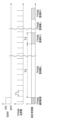
- 4 is a time chart for explaining the operation of the TPMS transmitter and integrated receiver when the start switch is switched from on to off
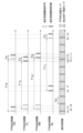
- FIG. 4 is a time chart for explaining operation modes and the like of the integrated receiver while the start switch is off
- FIG. 4 is a time chart for explaining frame transmission timing of a TPMS transmitter for each tire
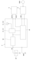
- Fig. 3 is a block diagram showing an integrated receiver
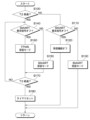
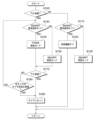
- 4 is a flowchart showing an example of reception processing executed by the integrated receiver while the start switch is off
- 9 is a flow chart showing an example of reception processing executed by the integrated receiver of the second embodiment while the start switch is off.
- 9 is a time chart for explaining frame transmission timings of the TPMS transmitter of each tire according to the third embodiment.
- FIG. 11 is a time chart for explaining frame transmission timings of a TPMS transmitter for
- FIG. 1 (First embodiment) This embodiment will be described with reference to FIGS. 1 to 7.
- FIG. "Front”, “rear”, “right” and “left” shown in FIG. 1 indicate “front”, “rear”, “right” and “left” of the vehicle 1.
- the tire pressure monitoring system is a system that monitors the tire pressure of tires attached to a plurality of wheels 10a-10d.
- Tire pressure is the pressure inside the tire.
- the tire pressure monitoring system may be referred to as "TPMS" hereinafter.
- the TPMS includes a plurality of TPMS transmitters 2a-2d attached to the tires of each wheel 10a-10d and an integrated receiver 3 attached to the vehicle body 11 side of the vehicle 1.
- the TPMS transmitters 2a to 2d detect the tire air pressure of the tires to which they are mounted, and transmit a frame containing information on the tire air pressure (for example, a tire air pressure detection signal) at a predetermined regular transmission cycle T1. machine. As shown in FIG. 2, the TPMS transmitters 2a to 2d are provided with a sensor section 21, a sensor control section 22, and a radio wave transmission section .
- the sensor unit 21 includes a pressure sensor 21a that detects the pressure inside the tire and a temperature sensor 21b that detects the temperature inside the tire.
- the sensor unit 21 outputs a detection signal from the pressure sensor 21 a and a detection signal from the temperature sensor 21 b to the sensor control unit 22 .
- the sensor control unit 22 is composed of a processor, a microcomputer including memory, and its peripherals.
- the sensor control unit 22 executes transmission processing and the like according to programs stored in the memory.
- the memory of the sensor control unit 22 stores ID information including transmitter-specific identification information for identifying each of the TPMS transmitters 2a to 2d and vehicle-specific identification information for identifying the vehicle 1. there is Note that the memory is composed of a non-transitional material storage medium.
- the sensor control unit 22 When the sensor control unit 22 receives the detection signal output by the sensor unit 21, the sensor control unit 22 performs signal processing on the detection signal, processes it as necessary, and stores it in the frame together with the ID information as data indicating the detection result. The sensor control unit 22 then sends the frame to the radio wave transmission unit 23 .
- the radio wave transmission section 23 has an output section 231 and a transmission antenna section 232 .
- the output unit 231 transmits the frame sent from the sensor control unit 22 to the integrated receiver 3 through the transmission antenna unit 232 as radio waves (for example, RF radio waves) of a predetermined frequency band.
- the TPMS transmitters 2a to 2d are not provided with a function to receive signals from the outside, and cannot determine whether the start switch SSW of the vehicle 1 is on or off.
- the process of sending a signal from the sensor control unit 22 to the radio wave transmission unit 23 is executed at predetermined periodic transmission intervals T1 regardless of whether the start switch SSW is turned on or off, as shown in FIG. That is, the TPMS transmitters 2a to 2d are configured to perform frame transmission every predetermined periodical transmission cycle T1.
- the start switch SSW corresponds to, for example, an ignition switch in an engine-equipped vehicle and a power switch in an EV vehicle.
- the TPMS transmitters 2a to 2d of this embodiment transmit frames multiple times at a transmission interval T4 that is shorter than the regular transmission cycle T1.
- the TPMS transmitters 2a to 2d transmit frames at regular transmission periods T1 and at predetermined transmission intervals T4 from the transmission of the frames.
- the transmission interval T4 in this embodiment is the same time interval for each of the TPMS transmitters 2a to 2d.
- the frame is transmitted twice in each periodic transmission period T1, but the frame may be transmitted three times or more.
- the transmission interval T4 between the first and second transmissions and the transmission interval T4 between the second and third transmissions may be the same or different.
- the transmission interval T between the first and second transmissions may be constant, and the transmission interval T4 between the second and third transmissions may be random.
- each of the TPMS transmitters 2a to 2d has its frame transmission timing set so that frame transmission and the timing at which the output of a SMART request signal RCO described later is turned on are unlikely to overlap.
- Each of the TPMS transmitters 2a to 2d is set such that the frame transmission interval T4 does not coincide with an integral multiple of a first intermittent period T5, which will be described later.
- the frame transmission interval T4 is set to a time interval shorter than a first intermittent period T5, which will be described later.
- each of the TPMS transmitters 2a to 2d can change the regular transmission cycle T1 within a predetermined reference range in order to avoid overlapping of frame transmission timings.
- each of the TPMS transmitters 2a to 2d obtains the regular transmission cycle T1 by adding or subtracting a random number generated by a random number function or the like to or from the reference time, and transmits a frame every regular transmission cycle T1.
- the periodic transmission cycle T1 is randomly changed each time.
- the periodic transmission period T1a of the TPMS transmitter 2a on the left front tire FL is the shortest
- the periodic transmission period T1c of the TPMS transmitter 2c on the left rear tire RL is the longest.
- the regular transmission cycle T1b of the TPMS transmitter 2b of the right front tire FR is shorter than the regular transmission cycle T1d of the TPMS transmitter 2d of the right rear tire RR.
- the TPMS transmitters 2a to 2d configured in this way are attached to the air valves of the tires of the wheels 10a to 10d so that, for example, the sensor units 21 are located in the internal space of the tire.
- the integrated receiver 3 is an in-vehicle receiver attached to the vehicle body 11 side.
- the integrated receiver 3 constitutes a part of the TPMS and a part of the Smart Entry (registered trademark) system.
- the integrated receiver 3 has a function as a receiver for receiving frames transmitted by the TPMS transmitters 2a to 2d and a function as a receiver for receiving specific radio waves emitted by the portable device 4 such as an electronic key.
- the radio waves emitted by the TPMS transmitters 2a to 2d and the specific radio waves emitted by the portable device 4 have different frequencies.
- the smart entry system when the portable device 4 owned by the authorized user of the vehicle 1 enters the wireless communication area around the vehicle 1, the communication between the portable device 4 and the authentication ECU 5 through the integrated receiver 3 It is a system that performs authentication by wireless communication.
- the smart entry system may be referred to as "SMART" hereinafter.
- the authentication ECU 5 performs control to confirm whether or not the portable device 4 exists in the wireless communication area around the vehicle 1 .
- the authentication ECU 5 has, for example, a voltage signal terminal connected to the integrated receiver 3 while the start switch SSW is off, as shown in FIG.
- the authentication ECU 5 turns on the SMART request signal RCO, which is the output of the voltage signal terminal, every predetermined first intermittent period T5 to switch the operation mode of the integrated receiver 3 .
- the operation mode of the integrated receiver 3 shifts to the SMART reception mode in which the specific radio wave from the portable device 4 can be received. Also, when the SMART request signal RCO is turned off, the operation mode of the integrated receiver 3 shifts to a power saving mode or a TPMS reception mode which will be described later.
- the authentication ECU 5 authenticates whether the portable device 4 belongs to a legitimate user.
- the authentication ECU 5 executes various controls such as unlocking of the doors of the vehicle 1 and permission to start the driving source (for example, the engine) of the vehicle 1 when the authentication is established.
- the integrated receiver 3 includes a radio wave receiving section 31 , a power supply adjusting section 32 and a TPMS control section 33 .
- the radio wave receiving section 31 has an input section 311 and a receiving antenna section 312 .
- the input unit 311 receives frames sent from the TPMS transmitters 2a to 2d and specific radio waves emitted by the portable device 4 through the receiving antenna unit 312 .
- the radio wave receiving unit 31 can change the reception frequency so that the specific radio waves emitted by the portable device 4 can be received with priority over the radio waves emitted by the TPMS transmitters 2a to 2d. For example, while the SMART request signal RCO is on, the radio wave receiving unit 31 adjusts the reception frequency to a frequency capable of receiving the specific radio wave emitted by the portable device 4 so that the reception of the specific radio wave is given priority over the reception of the frame. change. While the SMART request signal RCO is off, the radio wave receiving unit 31 changes the reception frequency to a frequency capable of receiving the radio waves emitted by the TPMS transmitters 2a to 2d based on the control signal emitted by the TPMS control unit 33.
- the radio wave receiving unit 31 Upon receiving the specific radio wave emitted by the portable device 4 , the radio wave receiving unit 31 outputs DATA related to door locking, unlocking, etc. included in the specific radio wave to the authentication ECU 5 . Further, the radio wave receiving section 31 outputs frames generated by the TPMS transmitters 2 a to 2 d to the TPMS control section 33 . Note that the method of changing the reception frequency of the input unit 311 described above is an example. The integrated receiver 3 may be adapted to change the reception frequency in a manner different from that described above.
- the power supply adjustment unit 32 generates power for driving the radio wave reception unit 31 and the TPMS control unit 33 of the integrated receiver 3 from a predetermined voltage (+B) applied from the battery BT.
- the integrated receiver 3 operates based on power generated by the power regulator 32 .
- the TPMS control unit 33 is composed of a processor, a microcomputer including memory, and its peripherals.
- the TPMS control unit 33 executes predetermined processing according to programs stored in the memory.
- the memory is composed of a non-transitional material storage medium.
- the TPMS control unit 33 is in an active operation mode while the start switch SSW is on, and the radio wave reception unit 31 receives radio waves and the TPMS control unit 33 executes various processes related to tire air pressure monitoring at any time.
- the TPMS control section 33 constitutes a "control section" that detects the occurrence of a decrease in tire air pressure based on tire air pressure data contained in frames transmitted from the TPMS transmitters 2a to 2d.
- the TPMS control unit 33 basically enters a power saving mode such as a sleep mode that consumes less power. active mode of operation. In the power saving mode, functions of the radio wave receiving unit 31 and the TPMS control unit 33 are restricted, thereby suppressing dark current in the integrated receiver 3 .
- the tire air pressure may drop below a predetermined alarm threshold while the start switch SSW is off. Therefore, it is desirable to continue monitoring the tire pressure by the TPMS even while the start switch SSW is off.
- the TPMS control unit 33 shifts to the SMART reception mode at each predetermined first intermittent period T5 while the start switch SSW is off, and shifts to the SMART reception mode at each predetermined second intermittent period T2. Switch from power saving mode to TPMS reception mode.
- the SMART reception mode is an operation mode in which the radio wave reception unit 31 receives specific radio waves emitted by the portable device 4 .
- the TPMS control unit 33 outputs a control signal to that effect to the radio wave receiving unit 31, and the reception frequency of the radio wave receiving unit 31 is specified by the portable device 4. Switch to a frequency that can receive radio waves.
- the TPMS reception mode is an operation mode in which the radio wave reception unit 31 receives frames and intermittently monitors the tire air pressure.
- the TPMS control unit 33 outputs, for example, a control signal instructing frame reception to the radio wave receiving unit 31 every predetermined second intermittent period T2, and sets the reception frequency of the radio wave receiving unit 31 to the TPMS transmitters 2a to 31. Switch to a receivable frequency for the radio waves emitted by 2d.
- the operation mode of the integrated receiver 3 while the start switch SSW is off is switched to the power saving mode, the SMART reception mode, and the TPMS reception mode.
- the SMART reception mode is a "specific mode” in which the radio wave receiving section 31 of the integrated receiver 3 receives a specific radio wave at each predetermined first intermittent period T5.
- the TPMS reception mode is a "monitoring mode” in which the radio wave receiving section 31 of the integrated receiver 3 receives frames at predetermined second intermittent intervals T2 to intermittently monitor the tire air pressure.
- the power saving mode is an operation mode that consumes less power than the SMART reception mode and the TPMS reception mode.
- the TPMS control unit 33 When the TPMS control unit 33 receives a frame from the radio wave receiving unit 31, it monitors the occurrence of a decrease in tire air pressure based on the tire air pressure data contained in the received frame. Specifically, the TPMS control unit 33 obtains the tire air pressure by performing various signal processing and calculations based on the tire air pressure data stored in the frame. Then, the monitoring control unit 331 outputs an electrical signal corresponding to the obtained tire air pressure to the external device 6 including an in-vehicle display via CAN or the like. For example, the monitoring control unit 331 compares the tire air pressure with a predetermined alarm threshold value, and outputs a signal to that effect to the external device 6 when detecting that the tire air pressure has decreased below the predetermined alarm threshold value. Note that the monitoring control unit 331 can obtain the tire air pressure of each of the four wheels 10a to 10d, and display the tire air pressure on the vehicle-mounted display in association with each of the wheels 10a to 10d.
- the memory of the TPMS control unit 33 stores the ID information of the TPMS transmitters 2a-2d arranged on the wheels 10a-10d in association with the positions of the wheels 10a-10d. For this reason, the TPMS control unit 33 checks the ID information stored in the frame to recognize which of the wheels 10a to 10d the TPMS transmitter 2a to 2d is attached to the received frame. A wheel with low air pressure can be identified. Based on this, when a decrease in tire air pressure occurs, the wheel with the decreased air pressure is identified and displayed on the vehicle-mounted display.
- the cycle of monitoring the tire pressure while the start switch SSW is off is longer than the cycle of receiving the specific radio waves emitted by the portable device 4 . That is, the second intermittent period T2 is longer than the first intermittent period T5.
- This second intermittent period T2 is preferably set to several hours, for example.
- the first intermittent period T5 is set to, for example, one second or less.
- the monitoring time T3 is set to a time longer than the periodical transmission period T1 of frames by the TPMS transmitters 2a to 2d. Considering interference of frames from the TPMS transmitters 2a to 2d, it is desirable that the monitoring time T3 is set to be at least twice the periodical transmission period T1. Also, in consideration of an increase in dark current, the monitoring time T3 is set shorter than the second intermittent period T2.
- the TPMS according to this embodiment is configured as described above. Next, the operation of the TPMS of this embodiment will be described.
- the TPMS receives frames transmitted from each of the TPMS transmitters 2a to 2d while the start switch SSW is on, and monitors the above-described tire air pressure based on the received frames. do.
- the TPMS receives specific radio waves emitted by the portable device 4 and intermittently receives frames transmitted from the TPMS transmitters 2a to 2d. to perform tire pressure monitoring.
- An example of control processing executed by the integrated receiver 3 while the start switch SSW is off will be described below with reference to FIG.
- the control process shown in FIG. 7 is periodically executed by the TPMS control unit 33 when the start switch SSW is turned off.
- the integrated receiver 3 determines whether or not the second intermittent period T2 has passed in step S100. This determination process is performed based on the time measured by the timer built into the TPMS control unit 33 .
- the integrated receiver 3 determines in step S110 whether or not the SMART request signal RCO is off. Specifically, the integrated receiver 3 determines that the SMART request signal RCO is off when the output of the voltage signal terminal is off. Further, the integrated receiver 3 determines that the SMART request signal RCO is on when the output of the voltage signal terminal is on.
- the integrated receiver 3 shifts to the power saving mode in step S120 and turns off the function of receiving the frame in the radio wave receiving unit 31 and the specific radio waves emitted by the portable device 4 . After that, the integrated receiver 3 exits this process. If the SMART request signal RCO is on, the integrated receiver 3 shifts to the SMART reception mode in step S130 and turns on the specific radio wave reception function in the radio wave reception section 31 . After that, the integrated receiver 3 exits this process.
- the integrated receiver 3 determines in step S140 whether or not the SMART request signal RCO is off. Specifically, the integrated receiver 3 determines that the SMART request signal RCO is off when the output of the voltage signal terminal is off. Further, the integrated receiver 3 determines that the SMART request signal RCO is on when the output of the voltage signal terminal is on.
- the integrated receiver 3 When the SMART request signal RCO is on, the integrated receiver 3 shifts to the SMART reception mode in step S150 and turns on the specific radio wave reception function in the radio wave reception section 31 . If the SMART request signal RCO is off, the integrated receiver 3 shifts to the TPMS reception mode in step S160 and turns on the frame reception function of the radio wave reception section 31 .
- the integrated receiver 3 determines in step S170 whether or not the monitoring time T3 has elapsed. This determination process is performed based on the time measured by the timer built into the TPMS control unit 33 .
- the integrated receiver 3 If the time measured by the timer has not passed the monitoring time T3, the integrated receiver 3 returns to step S140 and again determines whether the SMART request signal RCO is off. On the other hand, when the time measured by the timer has passed the monitoring time T3, the integrated receiver 3 resets the timer in step S180 and exits this process.
- the TPMS integrated receiver 3 described above shifts to the SMART reception mode every predetermined first intermittent period T5 while the start switch SSW is off, and shifts to the TPMS reception mode every predetermined second intermittent period T2. do. According to this, while the start switch SSW is off, the specific radio wave is received and the tire pressure is monitored intermittently, so the operating time of the integrated receiver 3 can be reduced while the start switch SSW is off. . Therefore, it is possible to receive the specific radio wave and monitor the tire pressure while suppressing an increase in dark current in the integrated receiver 3 . Since the TPMS of this embodiment monitors the tire air pressure even while the start switch SSW is turned off, it is possible to notify the user of the decrease in the tire air pressure at an early stage.
- the second intermittent period T2 is longer than the first intermittent period T5. While the start switch SSW is off, a non-monitoring period in which the SMART reception mode and the power saving mode are alternately switched and a monitoring period in which the SMART reception mode and the TPMS reception mode are alternately switched are alternately repeated. This increases the time during which the tire pressure is not monitored while the start switch SSW is off, so that it is possible to suppress an increase in dark current in the integrated receiver 3 while the start switch SSW is off.
- the tire pressure monitoring time T3 in the TPMS reception mode is longer than the regular transmission cycle T1.
- the monitoring time T3 is made longer than the periodical transmission period T1 of the frame, the integrated receiver 3 can easily receive the frame appropriately.
- the TPMS transmitters 2a to 2d of this embodiment transmit frames multiple times at a transmission interval T4 that is shorter than the regular transmission cycle T1. According to this, the frames transmitted by the TPMS transmitters 2a to 2d can be appropriately received by the integrated receiver 3.
- FIG. 1 A transmission interval T4 that is shorter than the regular transmission cycle T1.
- the frame transmission timing of the TPMS transmitter 2b does not coincide with the timing when the SMART request signal RCO is turned on. can do.
- the transmission interval T4 is a time interval different from the integral multiple of the first intermittent period T5. According to this, it is possible to prevent the timing of frame transmission from continuously overlapping the timing at which the SMART request signal RCO is turned on. easier to receive.
- the transmission interval T4 is a time interval shorter than the first intermittent period T5. This makes it easier for the integrated receiver 3 to receive the frames transmitted by the TPMS transmitters 2a to 2d in a short period of time.
- Each of the TPMS transmitters 2a to 2d can change the periodic transmission period T1 within a predetermined reference range. According to this, it is possible to prevent the frames transmitted by the TPMS transmitters 2a to 2d from arriving at the integrated receiver 3 at the same timing continuously. can be properly received by machine 3.
- the integrated receiver 3 cannot properly receive the frame.
- the regular transmission cycle T1a of the TPMS transmitter 2a of the left front tire FL is shorter than the regular transmission cycle T1d of the TPMS transmitter 2d of the right rear tire RR.
- the frame transmission timing of the TPMS transmitter 2a on the left front tire FL is the frame transmission timing of the TPMS transmitter 2d on the right rear tire RR. does not overlap with Therefore, the integrated receiver 3 can receive the frame transmitted from the TPMS transmitter 2a of the left front tire FL.
- the frame transmission timing of the TPMS transmitter 2a of the right rear tire RR is the same as the frame transmission timing of the TPMS transmitter 2d of the left front tire FL. no longer overlap. Therefore, the integrated receiver 3 can receive the frame transmitted from the TPMS transmitter 2d of the right rear tire RR.
- the frame transmission timing of the TPMS transmitter 2c of the left rear tire RL shown at the bottom of FIG. It does not overlap with the timing when the signal RCO is turned on. Therefore, at times te, tf, tm, and tn, the integrated receiver 3 can receive frames transmitted from the TPMS transmitter 2d of the right rear tire RR.
- FIG. 8 corresponds to the flowchart of FIG. 7 described in the first embodiment. Since each process of steps S100 to S180 in FIG. 8 is the same as each process of steps S100 to S180 in FIG. 7, description thereof will be omitted.
- step S170 when it is determined in step S170 that the monitoring time T3 has not elapsed, the integrated receiver 3 proceeds to step S190.
- step S190 the integrated receiver 3 determines whether the reception of frames from all the TPMS transmitters 2a to 2d has been completed and the tire pressures of all the tires have been received.
- step S140 determines whether the SMART request signal RCO is off. On the other hand, if the tire pressures of all tires have been received, the integrated receiver 3 resets the timer in step S180 and exits this process.
- the integrated receiver 3 of the present embodiment can obtain the same effects as in the first embodiment from the same or equivalent configuration as the first embodiment.
- the TPMS control unit 33 When the TPMS control unit 33 completes receiving frames from the TPMS transmitters 2a to 2d in the TPMS reception mode, it shifts to the power saving mode. According to this, wasteful operation of the integrated receiver 3 while the start switch SSW is off can be suppressed, and an increase in dark current in the integrated receiver 3 can be sufficiently suppressed.
- the frame transmission interval T4 is the same time interval for each of the TPMS transmitters 2a to 2d.
- the frame transmission interval T4 can be changed within a predetermined range in order to avoid overlapping of frame transmission timings in the TPMS transmitters 2a to 2d.
- each of the TPMS transmitters 2a to 2d obtains the transmission interval T4 by adding or subtracting a random number generated by a random number function or the like to or from the reference interval, and transmits frames at the transmission interval T4.
- the frame transmission interval T4 is randomly changed each time.
- the transmission interval T4b of the TPMS transmitter 2b on the right front tire FR is the shortest
- the transmission interval T4d of the TPMS transmitter 2d on the right rear tire RR is the longest.
- the transmission interval T4a of the TPMS transmitter 2a on the left front tire FL is longer than the transmission interval T4c of the TPMS transmitter 2c on the left rear tire RL.
- the integrated receiver 3 of the present embodiment can obtain the same effects as in the first embodiment from the same or equivalent configuration as the first embodiment.
- Each of the TPMS transmitters 2a to 2d can change the frame transmission interval T4 within a predetermined range. According to this, it is possible to prevent the frames transmitted by the TPMS transmitters 2a to 2d from arriving at the integrated receiver 3 at the same timing continuously. can be properly received by machine 3.
- the integrated receiver 3 cannot receive the frame.
- the transmission interval T4a of the TPMS transmitter 2a on the left front tire FL is shorter than the transmission interval T4d of the TPMS transmitter 2d on the right rear tire RR.
- the integrated receiver 3 can receive the frame transmitted from the TPMS transmitter 2a of the left front tire FL.
- the integrated receiver 3 can receive the frame transmitted from the TPMS transmitter 2d of the right rear tire RR.
- the TPMS may be configured such that one of the frame transmission interval T4 and the regular transmission period T1 in each of the TPMS transmitters 2a to 2d can be changed, and the other time cannot be changed.
- Each of the TPMS transmitters 2a to 2d of the first embodiment is configured to transmit frames multiple times at a transmission interval T4 that is shorter than the regular transmission cycle T1.
- each of the TPMS transmitters 2a-2d of the present embodiment is configured to continuously transmit frames multiple times.
- each TPMS transmitter 2a-2d is configured to transmit frames three times in succession. Note that the number of consecutive frame transmissions is not limited to three, and may be two or four or more.
- the integrated receiver 3 of the present embodiment can obtain the same effects as in the first embodiment from the same or equivalent configuration as the first embodiment.
- a plurality of TPMS transmitters 2a-2d continuously transmit frames multiple times. This also makes it difficult for the frames transmitted by the plurality of TPMS transmitters 2a to 2d to arrive at the integrated receiver 3 at the same timing. receive easily.
- the TPMS control unit 33 changes the time interval of the second intermittent period T2 within a predetermined range.
- the integrated receiver 3 of the present embodiment can obtain the same effects as in the first embodiment from the same or equivalent configuration as the first embodiment.
- the time interval of the second intermittent period T2 changes within a predetermined range. According to this, it can be expected that wasteful operations in the integrated receiver 3 are suppressed and an increase in dark current in the integrated receiver 3 is sufficiently suppressed.
- the TPMS control unit 33 may change the time interval of the second intermittent cycle T2 periodically or irregularly within a predetermined range.
- the second intermittent period T2 is longer than the first intermittent period T5, but it does not have to be.
- the monitoring time T3 is longer than the periodic transmission cycle T1, but the monitoring time T3 is not limited to this, and may be shorter than the periodic transmission cycle T1, for example. .
- the TPMS transmitters 2a to 2d transmit frames multiple times at transmission intervals T4 that are shorter than the regular transmission cycle T1, but this does not have to be the case.
- the transmission interval T4 be a time interval different from the integral multiple of the first intermittent period T5, but it does not have to be. Moreover, although it is desirable that the transmission interval T4 is a time interval shorter than the first intermittent period T5, it does not have to be.
- the TPMS transmitters 2a to 2d are capable of changing the transmission interval T4 within a predetermined range, but this need not be the case.
- the TPMS transmitters 2a to 2d be able to change the periodic transmission period T1 within a predetermined reference range, but this does not have to be the case.
- the integrated receiver 3 for example, predicts the frame transmission timing of the TPMS transmitters 2a-2d based on the time when the TPMS transmitters 2a-2d are received, and uses the prediction result to adjust the tire pressure monitoring timing. It is desirable that the
- the transmission interval T4 is set to a time interval longer than the operation time of the SMART reception mode when receiving the specific radio wave emitted by the portable device 4 .
- the TPMS applied to the vehicle 1 having four wheels 10a to 10d has been described, but the present disclosure is applicable to vehicles having three wheels and vehicles having five or more wheels. .
- the controller and techniques of the present disclosure may be implemented on a dedicated computer provided by configuring a processor and memory programmed to perform one or more functions embodied by the computer program. good too.
- the controller and techniques of the present disclosure may be implemented in a dedicated computer provided by configuring the processor with one or more dedicated hardware logic circuits.
- the control unit and method of the present disclosure is a combination of a processor and memory programmed to perform one or more functions and a processor configured by one or more hardware logic circuits. It may be implemented on one or more dedicated computers.
- the computer program may also be stored as computer-executable instructions on a computer-readable non-transitional tangible recording medium.
Landscapes
- Engineering & Computer Science (AREA)
- Mechanical Engineering (AREA)
- Physics & Mathematics (AREA)
- General Physics & Mathematics (AREA)
- Measuring Fluid Pressure (AREA)
Abstract
車載受信機は、タイヤ空気圧の監視システムに含まれる。車載受信機は、複数個の車輪の前記タイヤそれぞれに備えられた送信機(2a~2d)が所定の定期送信周期(T1)で送信するタイヤ空気圧に関する情報を含むフレームおよび携帯機(4)が発する特定電波を受信する電波受信部(31)を備える。車載受信機は、フレームに含まれるタイヤ空気圧に関するデータに基づいてタイヤ空気圧低下の発生を検出する制御部(33)を備える。制御部は、車両の始動スイッチ(SSW)のオフ中には、所定の第1間欠周期(T5)毎に電波受信部にて特定電波の受信を行わせる特定モードに移行する。また、制御部は、車両の始動スイッチ(SSW)のオフ中には、所定の第2間欠周期(T2)毎に電波受信部にてフレームの受信を行わせて間欠的にタイヤ空気圧を監視する監視モードに特定モードまたは省電力モードから移行する。
Description
本出願は、2022年1月12日に出願された日本特許出願番号2022-003329号に基づくもので、ここにその記載内容が参照により組み入れられる。
本開示は、車載受信機、タイヤ空気圧の監視システムに関する。
従来、タイヤ空気圧の監視システムとして、車両の始動スイッチのオン中だけでなくオフ中にも、送信機から送信されるフレームを車載受信機で受信し、フレーム内の情報を解析してタイヤ空気圧の低下を検出するものが知られている(例えば、特許文献1参照)。これとは別に、始動スイッチのオン中にタイヤに取り付けられた送信機から送信されるフレームを車載受信機で受信し、始動スイッチのオフ中に電子キー等の携帯機が発する特定電波を車載受信機で受信するものも知られている。
本発明者らは、タイヤ空気圧の監視システムにおいて、始動スイッチのオフ中に、車載受信機にて、携帯機が発する特定電波に加えて、タイヤ空気圧に関する情報を含むフレームを受信することを検討した。この検討において、単に、始動スイッチのオフ中に、フレームおよび特定電波を別個に受信しようとすると、始動スイッチのオフ中における車載受信機の動作時間が増加して、車載受信機における暗電流の大幅な増加が生じることが明らかになった。
本開示は、始動スイッチのオフ中における暗電流の増加を抑制しつつ、タイヤ空気圧に関する情報を含むフレームおよび携帯機が発する特定電波の双方を受信可能な車載受信機、タイヤ空気圧の監視システムを提供することを目的とする。
本開示は、始動スイッチのオフ中における暗電流の増加を抑制しつつ、タイヤ空気圧に関する情報を含むフレームおよび携帯機が発する特定電波の双方を受信可能な車載受信機、タイヤ空気圧の監視システムを提供することを目的とする。
本開示の1つの観点によれば、
車載受信機は、
タイヤを備えた複数個の車輪を有する車両に適用されるタイヤ空気圧の監視システムに含まれるものであって、
複数個の車輪のタイヤそれぞれに備えられた送信機が所定の定期送信周期で送信するタイヤ空気圧に関する情報を含むフレームおよび携帯機が発する特定電波を受信する電波受信部と、
フレームに含まれるタイヤ空気圧に関するデータに基づいてタイヤ空気圧低下の発生を検出する制御部と、を備え、
制御部は、車両の始動スイッチのオフ中には、所定の第1間欠周期毎に電波受信部にて特定電波の受信を行わせる特定モードに移行し、所定の第2間欠周期毎に電波受信部にてフレームの受信を行わせて間欠的にタイヤ空気圧を監視する監視モードに特定モードまたは省電力モードから移行する。
車載受信機は、
タイヤを備えた複数個の車輪を有する車両に適用されるタイヤ空気圧の監視システムに含まれるものであって、
複数個の車輪のタイヤそれぞれに備えられた送信機が所定の定期送信周期で送信するタイヤ空気圧に関する情報を含むフレームおよび携帯機が発する特定電波を受信する電波受信部と、
フレームに含まれるタイヤ空気圧に関するデータに基づいてタイヤ空気圧低下の発生を検出する制御部と、を備え、
制御部は、車両の始動スイッチのオフ中には、所定の第1間欠周期毎に電波受信部にて特定電波の受信を行わせる特定モードに移行し、所定の第2間欠周期毎に電波受信部にてフレームの受信を行わせて間欠的にタイヤ空気圧を監視する監視モードに特定モードまたは省電力モードから移行する。
本開示の別の観点によれば、
タイヤ空気圧の監視システムは、
タイヤを備えた複数個の車輪を有する車両に適用されるものであって、
複数個の車輪のタイヤそれぞれに備えられ、タイヤ空気圧に関する情報を含むフレームを所定の定期送信周期で送信する複数の送信機と、
車体側に備えられた車載受信機と、を備え、
車載受信機は、
フレームおよび携帯機が発する特定電波を受信する電波受信部と、
フレームに含まれるタイヤ空気圧に関するデータに基づいてタイヤ空気圧低下の発生を検出する制御部と、を備え、
制御部は、車両の始動スイッチのオフ中には、所定の第1間欠周期毎に電波受信部にて特定電波の受信を行わせる特定モードに移行し、所定の第2間欠周期毎に電波受信部にてフレームの受信を行わせて間欠的にタイヤ空気圧を監視する監視モードに特定モードまたは省電力モードから移行する。
タイヤ空気圧の監視システムは、
タイヤを備えた複数個の車輪を有する車両に適用されるものであって、
複数個の車輪のタイヤそれぞれに備えられ、タイヤ空気圧に関する情報を含むフレームを所定の定期送信周期で送信する複数の送信機と、
車体側に備えられた車載受信機と、を備え、
車載受信機は、
フレームおよび携帯機が発する特定電波を受信する電波受信部と、
フレームに含まれるタイヤ空気圧に関するデータに基づいてタイヤ空気圧低下の発生を検出する制御部と、を備え、
制御部は、車両の始動スイッチのオフ中には、所定の第1間欠周期毎に電波受信部にて特定電波の受信を行わせる特定モードに移行し、所定の第2間欠周期毎に電波受信部にてフレームの受信を行わせて間欠的にタイヤ空気圧を監視する監視モードに特定モードまたは省電力モードから移行する。
これらによれば、始動スイッチのオフ中には、特定電波の受信およびタイヤ空気圧の監視が間欠的に実施されるので、始動スイッチのオフ中における車載受信機の動作時間を抑えることができる。したがって、車載受信機における暗電流の増加を抑制しつつ、特定電波の受信およびタイヤ空気圧の監視を行うことが可能となる。
なお、各構成要素等に付された括弧付きの参照符号は、その構成要素等と後述する実施形態に記載の具体的な構成要素等との対応関係の一例を示すものである。
以下、本開示の実施形態について図面を参照して説明する。なお、以下の実施形態において、先行する実施形態で説明した事項と同一もしくは均等である部分には、同一の参照符号を付し、その説明を省略する場合がある。また、実施形態において、構成要素の一部だけを説明している場合、構成要素の他の部分に関しては、先行する実施形態において説明した構成要素を適用することができる。以下の実施形態は、特に組み合わせに支障が生じない範囲であれば、特に明示していない場合であっても、各実施形態同士を部分的に組み合わせることができる。
(第1実施形態)
本実施形態について、図1~図7を参照して説明する。なお、図1に示す「前」、「後」、「右」、「左」は、車両1の「前方」、「後方」、「右方」、「左方」を示している。
本実施形態について、図1~図7を参照して説明する。なお、図1に示す「前」、「後」、「右」、「左」は、車両1の「前方」、「後方」、「右方」、「左方」を示している。
タイヤ空気圧の監視システムは、複数個の車輪10a~10dに取り付けられたタイヤのタイヤ空気圧を監視するシステムである。タイヤ空気圧は、タイヤ内部の圧力である。なお、便宜上、以下では、タイヤ空気圧の監視システムを“TPMS”と表記することがある。
図1に示すように、TPMSは、各車輪10a~10dのタイヤに取り付けられた複数のTPMS送信機2a~2dと、車両1の車体11側に取り付けられた統合受信機3とを備える。
TPMS送信機2a~2dは、自身が取り付けられたタイヤのタイヤ空気圧を検出するとともに、当該タイヤ空気圧に関する情報(例えば、タイヤ空気圧の検出信号)を含むフレームを所定の定期送信周期T1で送信する送信機である。図2に示すように、TPMS送信機2a~2dは、センサ部21、センサ制御部22、電波送信部23を備える。
センサ部21は、タイヤ内部の圧力を検出する圧力センサ21aおよびタイヤ内部の温度を検出する温度センサ21bを備えている。センサ部21は圧力センサ21aの検出信号および温度センサ21bの検出信号をセンサ制御部22に向けて出力する。
センサ制御部22は、プロセッサ、メモリを含むマイクロコンピュータとその周辺機器によって構成されている。センサ制御部22は、メモリに記憶されたプログラムに従って、送信処理等を実行する。センサ制御部22のメモリには、各TPMS送信機2a~2dを特定するための送信機固有の識別情報と、車両1を特定するための車両固有の識別情報とを含むID情報が格納されている。なお、メモリは、非遷移的実体的記憶媒体で構成される。
センサ制御部22は、センサ部21が出力する検出信号を受け取ると、当該検出信号を信号処理するとともに、必要に応じて加工し、検出結果を示すデータとしてID情報とともにフレームに格納する。そして、センサ制御部22は、フレームを電波送信部23に送る。
電波送信部23は、出力部231および送信アンテナ部232を有する。出力部231は、送信アンテナ部232を通じて、センサ制御部22から送られてきたフレームを所定の周波数帯の電波(例えば、RF電波)として統合受信機3に向けて送信する。
TPMS送信機2a~2dは、外部からの信号を受信する機能が設けられておらず、車両1の始動スイッチSSWがオン中かオフ中かを判別できない。センサ制御部22から電波送信部23へ信号を送る処理は、図3に示すように、始動スイッチSSWのオンオフによらず、所定の定期送信周期T1毎に実行される。すなわち、TPMS送信機2a~2dは、所定の定期送信周期T1毎にフレーム送信を行うように構成されている。なお、始動スイッチSSWは、例えば、エンジン搭載車におけるイグニッションスイッチに対応し、EV車におけるパワースイッチに対応するスイッチである。
本実施形態のTPMS送信機2a~2dは、定期送信周期T1よりも小さい送信間隔T4でフレームを複数回送信する。例えば、図4および図5に示すように、TPMS送信機2a~2dは、定期送信周期T1でフレームを送信しつつ、当該フレームの送信から所定の送信間隔T4をあけてフレームを送信する。本実施形態の送信間隔T4は、各TPMS送信機2a~2dで同じ時間間隔になっている。なお、図4および図5に示す例では、定期送信周期T1毎にフレームを二回送信しているが、三回以上フレームを送信するようになっていてもよい。なお、三回以上フレームを送信する場合、例えば、一回目と二回目の送信間隔T4および二回目と三回目の送信間隔T4は、同じでもよいし異なっていてもよい。また、例えば、一回目と二回目の送信間隔Tが一定間隔となり、二回目と三回目の送信間隔T4がランダムとなっていてもよい。
ここで、各TPMS送信機2a~2dは、フレーム送信と後述のSMART要求信号RCOの出力がオンされるタイミングとが重なり難くなるように、フレーム送信のタイミングが設定されている。各TPMS送信機2a~2dは、フレームの送信間隔T4が、後述の第1間欠周期T5の整数倍と一致しないように設定されている。具体的には、フレームの送信間隔T4は、後述の第1間欠周期T5よりも小さい時間間隔に設定されている。
また、各TPMS送信機2a~2dは、フレーム送信のタイミングの重複を避けるべく、定期送信周期T1が所定の基準範囲内で変更可能になっている。例えば、各TPMS送信機2a~2dそれぞれは、基準時間に乱数関数等で生成したランダムな数値を加算または減算したものを定期送信周期T1として求め、当該定期送信周期T1毎にフレームを送信する。このようにして、定期送信周期T1が毎回ランダムに変更される。なお、図5に示す例では、左前タイヤFLのTPMS送信機2aの定期送信周期T1aが最も小さく、左後タイヤRLのTPMS送信機2cの定期送信周期T1cが最も大きくなっている。また、右前タイヤFRのTPMS送信機2bの定期送信周期T1bは、右後タイヤRRのTPMS送信機2dの定期送信周期T1dよりも小さくなっている。
このように構成されるTPMS送信機2a~2dは、例えば、センサ部21がタイヤの内部空間に位置するように、各車輪10a~10dのタイヤのエアバルブに取り付けられている。
統合受信機3は、車体11側に取り付けられた車載受信機である。統合受信機3は、TPMSの一部を構成するとともに、スマートエントリ(登録商標)システムの一部を構成する。統合受信機3は、TPMS送信機2a~2dが送信するフレームを受信する受信機としての機能に加えて、電子キー等の携帯機4が発する特定電波を受信する受信機としての機能を備える。なお、混信を避けるため、TPMS送信機2a~2dが発する電波と携帯機4が発する特定電波とは異なる周波数とされている。
ここで、スマートエントリシステムは、車両1の正規の利用者が所有する携帯機4が車両1の周囲の無線通信エリアに入った際に、統合受信機3を通して携帯機4と認証ECU5との間で無線通信による認証を行うシステムである。なお、便宜上、以下では、スマートエントリシステムを“SMART”と表記することがある。
認証ECU5は、携帯機4が車両1の周囲の無線通信エリアに存在するか否かを確認する制御を実施する。認証ECU5は、例えば、図4に示すように、始動スイッチSSWのオフ中に、統合受信機3に接続される電圧信号端子を有する。認証ECU5は、電圧信号端子の出力であるSMART要求信号RCOを所定の第1間欠周期T5毎にオンして、統合受信機3の動作モードを切り替える。
具体的には、SMART要求信号RCOがオンされると、統合受信機3の動作モードが携帯機4からの特定電波を受信可能なSMART受信モードに移行する。また、SMART要求信号RCOがオフされると、統合受信機3の動作モードが省電力モードまたは後述のTPMS受信モードに移行する。
認証ECU5は、携帯機4の存在が確認されると、当該携帯機4が正規の利用者が所有するものであるかを認証する。認証ECU5は、認証成立時には、車両1のドアのアンロックや車両1の駆動源(例えば、エンジン)の始動許可等の各種制御を実行する。
続いて、統合受信機3の主な構成について図6を参照しつつ説明する。図6に示すように、統合受信機3は、電波受信部31、電源調整部32、TPMS制御部33を備えている。
電波受信部31は、入力部311および受信アンテナ部312を有する。入力部311は、受信アンテナ部312を通じて、TPMS送信機2a~2dから送られてきたフレームおよび携帯機4が発する特定電波を受信する。
電波受信部31は、TPMS送信機2a~2dが発する電波よりも、携帯機4が発する特定電波を優先して受信可能なように、受信周波数を変更可能になっている。電波受信部31は、例えば、SMART要求信号RCOのオン中には、フレームの受信よりも特定電波の受信が優先されるように、携帯機4が発する特定電波を受信可能な周波数に受信周波数を変更する。なお、電波受信部31は、SMART要求信号RCOのオフ中にはTPMS制御部33が発する制御信号に基づいて、TPMS送信機2a~2dが発する電波を受信可能な周波数に受信周波数を変更する。
電波受信部31は、携帯機4が発する特定電波を受信すると、当該特定電波に含まれるドアのロック、アンロック等に関するDATAを認証ECU5に出力する。また、電波受信部31は、TPMS送信機2a~2dが発するフレームをTPMS制御部33に出力する。なお、上述した入力部311の受信周波数の変更方法は一例である。統合受信機3は、上述のものと異なる方法で受信周波数が変更されるようになっていてもよい。
電源調整部32は、バッテリBTから印加される所定電圧(+B)から統合受信機3の電波受信部31およびTPMS制御部33の駆動用電源を生成する。統合受信機3は、電源調整部32によって生成される電源に基づいて作動する。
TPMS制御部33は、プロセッサ、メモリを含むマイクロコンピュータとその周辺機器によって構成されている。TPMS制御部33は、メモリに記憶されたプログラムに従って、所定の処理を実行する。なお、メモリは、非遷移的実体的記憶媒体で構成される。
TPMS制御部33は、始動スイッチSSWのオン中にはアクティブな動作モードとなり、電波受信部31での電波受信やTPMS制御部33でのタイヤ空気圧の監視に関わる各種処理などが随時実行される。本実施形態では、TPMS制御部33が、TPMS送信機2a~2dから送信されるフレームに含まれるタイヤ空気圧に関するデータに基づいてタイヤ空気圧低下の発生を検出する“制御部”を構成している。
一方、TPMS制御部33は、始動スイッチSSWのオフ中には基本的にスリープモード等のように電力消費の小さい省電力モードとなるが、始動スイッチSSWのオフ中に所定条件が成立すると一時的にアクティブな動作モードに移行する。なお、省電力モードは、電波受信部31およびTPMS制御部33の機能が制限されることで、統合受信機3における暗電流が抑えられる。
ここで、タイヤ空気圧は、始動スイッチSSWのオフ中に所定の警報閾値以下に低下することがあり得る。このため、始動スイッチSSWのオフ中にもTPMSによるタイヤ空気圧の監視を継続することが望ましい。
しかしながら、単に、始動スイッチSSWのオフ中に、フレームおよび特定電波を別個に受信しようとすると、始動スイッチSSWのオフ中における統合受信機3の動作時間が増加して、統合受信機3における暗電流の大幅な増加が生じてしまう。なお、暗電流は、始動スイッチSSWのオフ中にも常時流れている待機電流である。
このことを加味し、TPMS制御部33は、始動スイッチSSWのオフ中には、所定の第1間欠周期T5毎にSMART受信モードに移行し、所定の第2間欠周期T2毎にSMART受信モードまたは省電力モードからTPMS受信モードに移行する。
SMART受信モードは、電波受信部31にて携帯機4が発する特定電波の受信を行わせる動作モードである。TPMS制御部33は、例えば、SMART要求信号RCOがオンされる毎に、その旨を示す制御信号を電波受信部31に出力して、電波受信部31の受信周波数を、携帯機4が発する特定電波を受信可能な周波数に切り替える。
TPMS受信モードは、電波受信部31にてフレームの受信を行わせて間欠的にタイヤ空気圧を監視する動作モードである。TPMS制御部33は、例えば、所定の第2間欠周期T2毎に、フレームの受信を指示する制御信号を電波受信部31に出力して、電波受信部31の受信周波数を、TPMS送信機2a~2dが発する電波を受信可能な周波数に切り替える。
このようにして、統合受信機3は、始動スイッチSSWのオフ中の動作モードが、省電力モード、SMART受信モード、TPMS受信モードに切り替えられる。なお、SMART受信モードは、所定の第1間欠周期T5毎に統合受信機3の電波受信部31にて特定電波の受信を行わせる“特定モード”である。TPMS受信モードは、所定の第2間欠周期T2毎に統合受信機3の電波受信部31にてフレームの受信を行わせて間欠的にタイヤ空気圧を監視する“監視モード”である。省電力モードは、SMART受信モードおよびTPMS受信モードに比べて、電力の消費量が小さい動作モードである。
TPMS制御部33は、電波受信部31からフレームを受け取ると、受け取ったフレームに含まれるタイヤ空気圧に関するデータに基づいてタイヤ空気圧低下の発生を監視する。具体的には、TPMS制御部33には、フレームに格納されたタイヤ空気圧に関するデータに基づいて各種信号処理および演算等を行うことでタイヤ空気圧を求める。そして、監視制御部331は、求めたタイヤ空気圧に応じた電気信号を、CAN等を介して、車載表示器を含む外部機器6に出力する。例えば、監視制御部331は、タイヤ空気圧を所定の警報閾値と比較し、タイヤ空気圧が所定の警報閾値以下に低下したことを検知した場合には、その旨の信号を外部機器6に出力する。なお、監視制御部331は、4つの車輪10a~10dそれぞれのタイヤ空気圧を求め、そのタイヤ空気圧を各車輪10a~10dと対応させて車載表示器に表示することもできる。
TPMS制御部33のメモリには、各車輪10a~10dに配置されているTPMS送信機2a~2dのID情報が各車輪10a~10dの位置と関連づけられて記憶されている。このため、TPMS制御部33は、フレームに格納されたID情報と照合することで、受信したフレームが車輪10a~10dのどれに取り付けられたTPMS送信機2a~2dであるかを認識し、タイヤ空気圧が低下した車輪を特定できる。これに基づき、タイヤ空気圧低下が発生した場合に、低下した車輪を特定して車載表示器に表示する。
ここで、始動スイッチSSWのオフ中におけるタイヤ空気圧の監視を行う周期は、小さくするほどリアルタイム性が向上するが、統合受信機3の暗電流も増加する。このため、始動スイッチSSWのオフ中におけるタイヤ空気圧の監視を行う周期は、携帯機4が発する特定電波を受信する周期よりも大きくなっている。すなわち、第2間欠周期T2は、第1間欠周期T5よりも大きくなっている。この第2間欠周期T2は、例えば、数時間に設定されていることが望ましい。なお、第1間欠周期T5は、例えば、1秒以下に設定される。これらにより、始動スイッチSSWのオフ中には、SMART受信モードおよび省電力モードが交互に切り替わる監視無し期間と、SMART受信モードおよびTPMS受信モードが交互に切り替わる監視有り期間とが交互に繰り返される。
また、タイヤ空気を監視する監視時間T3は、大きくするほど暗電流が増加するので小さい設定が望ましいが、小さすぎると、フレームを受信し難くなってしまう。このため、監視時間T3は、図3に示すように、TPMS送信機2a~2dによるフレームの定期送信周期T1よりも大きい時間に設定されている。TPMS送信機2a~2dからのフレームの混信等を考慮すると、監視時間T3は、定期送信周期T1の2倍以上に設定されていることが望ましい。また、暗電流の増加を考慮し、監視時間T3は、第2間欠周期T2よりも小さくなっている。
以上のようにして、本実施形態に係るTPMSが構成されている。続いて、本実施形態のTPMSの作動について説明する。
図3に示すように、TPMSは、始動スイッチSSWのオン中には、各TPMS送信機2a~2dから送信されるフレームを受信し、受信したフレームに基づいて、上述のタイヤ空気圧の監視を実施する。
一方、TPMSは、始動スイッチSSWのオフ中には、図4に示すように、携帯機4が発する特定電波の受信しつつ、間欠的に各TPMS送信機2a~2dから送信されるフレームを受信してタイヤ空気圧の監視を実施する。以下、始動スイッチSSWのオフ中に統合受信機3が実行する制御処理の一例について図7を参照しつつ説明する。図7に示す制御処理は、始動スイッチSSWがオフされると、周期的にTPMS制御部33によって実行される。
図7に示すように、統合受信機3は、ステップS100にて、第2間欠周期T2を経過したか否かを判定する。この判定処理は、TPMS制御部33の内蔵されたタイマの計測時間に基づいて実施される。
タイマの計測時間が第2間欠周期T2を経過していない場合、統合受信機3は、ステップS110にて、SMART要求信号RCOがオフであるか否かを判定する。具体的には、統合受信機3は、電圧信号端子の出力がオフの場合に、SMART要求信号RCOがオフされていると判定する。また、統合受信機3は、電圧信号端子の出力がオンの場合に、SMART要求信号RCOがオンされていると判定する。
SMART要求信号RCOがオフである場合、統合受信機3は、ステップS120にて、省電力モードに移行して、電波受信部31におけるフレームおよび携帯機4が発する特定電波の受信機能をオフする。その後、統合受信機3は本処理を抜ける。また、SMART要求信号RCOがオンである場合、統合受信機3は、ステップS130にて、SMART受信モードに移行して、電波受信部31における特定電波の受信機能をオンする。その後、統合受信機3は本処理を抜ける。
一方、タイマの計測時間が第2間欠周期T2を経過すると、統合受信機3は、ステップS140にて、SMART要求信号RCOがオフであるか否かを判定する。具体的には、統合受信機3は、電圧信号端子の出力がオフの場合に、SMART要求信号RCOがオフされていると判定する。また、統合受信機3は、電圧信号端子の出力がオンの場合に、SMART要求信号RCOがオンされていると判定する。
SMART要求信号RCOがオンである場合、統合受信機3は、ステップS150にて、SMART受信モードに移行して、電波受信部31における特定電波の受信機能をオンする。また、SMART要求信号RCOがオフである場合、統合受信機3は、ステップS160にて、TPMS受信モードに移行して、電波受信部31におけるフレームの受信機能をオンする。
ステップS150、S160にて動作モードの設定後、統合受信機3は、ステップS170にて、監視時間T3が経過したか否かを判定する。この判定処理は、TPMS制御部33の内蔵されたタイマの計測時間に基づいて実施される。
タイマの計測時間が監視時間T3を経過していない場合、統合受信機3は、ステップS140に戻り、再び、SMART要求信号RCOがオフであるか否かを判定する。一方、タイマの計測時間が監視時間T3を経過すると、統合受信機3は、ステップS180にて、タイマをリセットして、本処理を抜ける。
以上説明したTPMSの統合受信機3は、始動スイッチSSWのオフ中には、所定の第1間欠周期T5毎にSMART受信モードに移行し、所定の第2間欠周期T2毎にTPMS受信モードに移行する。これによると、始動スイッチSSWのオフ中には、特定電波の受信およびタイヤ空気圧の監視が間欠的に実施されるので、始動スイッチSSWのオフ中における統合受信機3の動作時間を抑えることができる。したがって、統合受信機3における暗電流の増加を抑制しつつ、特定電波の受信およびタイヤ空気圧の監視を行うことが可能となる。本実施形態のTPMSは、始動スイッチSSWのオフ中もタイヤ空気圧の監視を行うため、ユーザに向けて早期にタイヤ空気圧の低下を伝えることが可能となる。
(1)第2間欠周期T2は、第1間欠周期T5よりも大きくなっている。そして、始動スイッチSSWのオフ中には、SMART受信モードおよび省電力モードが交互に切り替わる監視無し期間と、SMART受信モードおよびTPMS受信モードが交互に切り替わる監視有り期間とが交互に繰り返される。これによると、始動スイッチSSWのオフ中におけるタイヤ空気圧を監視しない時間が増えるので、始動スイッチSSWのオフ中における統合受信機3での暗電流の増加を抑制することができる。
(2)TPMS受信モード時におけるタイヤ空気圧の監視時間T3は、定期送信周期T1よりも大きくなっている。このように、監視時間T3をフレームの定期送信周期T1よりも大きくすれば、統合受信機3でフレームを適切に受信し易くなる。
(3)本実施形態のTPMS送信機2a~2dは、定期送信周期T1よりも小さい送信間隔T4でフレームを複数回送信する。これによると、TPMS送信機2a~2dが送信するフレームを統合受信機3で適切に受信することができる。
例えば、図5の最上段に示す右前タイヤFRについては、時刻taにて、TPMS送信機2bのフレーム送信のタイミングが、SMART要求信号RCOがオンされるタイミングと重なっているので、統合受信機3にてフレームを受信することができない。
しかし、時刻taから送信間隔T4をあけた時刻tcでは、TPMS送信機2bのフレーム送信のタイミングが、SMART要求信号RCOがオンされるタイミングと重ならなくなるので、統合受信機3にてフレームを受信することができる。
(4)送信間隔T4は、第1間欠周期T5を整数倍したものとは異なる時間間隔になっている。これによると、フレーム送信のタイミングが、SMART要求信号RCOがオンされるタイミングと連続して重なることを避けることができるので、TPMS送信機2a~2dが送信するフレームを統合受信機3で適切に受信し易くなる。
(5)具体的には、送信間隔T4は、第1間欠周期T5よりも小さい時間間隔になっている。これによると、TPMS送信機2a~2dが送信するフレームを短期間に統合受信機3で受信し易くなる。
(6)TPMS送信機2a~2dそれぞれは、定期送信周期T1が所定の基準範囲内で変更可能になっている。これによると、TPMS送信機2a~2dそれぞれが送信するフレームが統合受信機3に届くタイミングが連続して一致することを避けることができるので、TPMS送信機2a~2dが送信するフレームを統合受信機3で適切に受信することができる。
例えば、図5の上から二段目、三段目に示すように、時刻tb、時刻tdでは、左前タイヤFLのTPMS送信機2aおよび右後タイヤRRのTPMS送信機2dのフレーム送信のタイミングが重なっている。このため、統合受信機3にてフレームを適切に受信することができない。
しかし、左前タイヤFLのTPMS送信機2aの定期送信周期T1aは、右後タイヤRRのTPMS送信機2dの定期送信周期T1dよりも小さくなっている。
これにより、時刻tb、tdから定期送信周期T1aをあけた時刻tg、tjでは、左前タイヤFLのTPMS送信機2aのフレーム送信のタイミングが、右後タイヤRRのTPMS送信機2dのフレーム送信のタイミングと重ならなくなる。このため、統合受信機3にて左前タイヤFLのTPMS送信機2aから送信されるフレームを受信することができる。
また、時刻tb、tdから定期送信周期T1dをあけた時刻ti、tlでは、右後タイヤRRのTPMS送信機2aのフレーム送信のタイミングが、左前タイヤFLのTPMS送信機2dのフレーム送信のタイミングと重ならなくなる。このため、統合受信機3にて右後タイヤRRのTPMS送信機2dから送信されるフレームを受信することができる。
なお、図5に示す例では、図5の最下段に示す左後タイヤRLのTPMS送信機2cのフレーム送信のタイミングは、他のTPMS送信機2a、2b、2dのフレーム送信のタイミングおよびSMART要求信号RCOがオンされるタイミングと重なっていない。このため、このため、時刻te、tf、tm、tnでは、統合受信機3にて右後タイヤRRのTPMS送信機2dから送信されるフレームを受信することができる。
(第2実施形態)
次に、第2実施形態について、図8を参照して説明する。本実施形態では、第1実施形態と異なる部分について主に説明する。
次に、第2実施形態について、図8を参照して説明する。本実施形態では、第1実施形態と異なる部分について主に説明する。
図8は、第1実施形態で説明した図7のフローチャートに対応している。図8のステップS100~S180の各処理は、図7のステップS100~S180の各処理と同じであるため、その説明を省略する。
図8に示すように、統合受信機3は、ステップS170にて監視時間T3が経過していないと判定されると、ステップS190に移行する。統合受信機3は、ステップS190にて、全てのTPMS送信機2a~2dからのフレームの受信が完了して、全タイヤのタイヤ空気圧を受信できたか否かを判定する。
統合受信機3は、全タイヤのタイヤ空気圧を受信できていない場合、ステップS140に戻り、再び、SMART要求信号RCOがオフであるか否かを判定する。一方、全タイヤのタイヤ空気圧を受信できている場合、統合受信機3は、ステップS180にて、タイマをリセットして、本処理を抜ける。
その他については、第1実施形態と同様である。本実施形態の統合受信機3は、第1実施形態と共通の構成または均等な構成から奏される効果を第1実施形態と同様に得ることができる。
また、本実施形態によれば、以下の効果を得ることができる。
(1)TPMS制御部33は、TPMS受信モード時にTPMS送信機2a~2dからのフレームの受信が完了すると、省電力モードに移行する。これによると、始動スイッチSSWのオフ中における統合受信機3の無駄な動作を抑制して、統合受信機3における暗電流の増加を充分に抑制することができる。
(第3実施形態)
次に、第3実施形態について、図9を参照して説明する。本実施形態では、第1実施形態と異なる部分について主に説明する。
次に、第3実施形態について、図9を参照して説明する。本実施形態では、第1実施形態と異なる部分について主に説明する。
第1実施形態のTPMSは、フレームの送信間隔T4が各TPMS送信機2a~2dで同じ時間間隔になっている。これに対して、本実施形態のTPMSは、各TPMS送信機2a~2dにおけるフレーム送信のタイミングの重複を避けるべく、フレームの送信間隔T4が所定範囲内で変更可能になっている。例えば、各TPMS送信機2a~2dそれぞれは、基準間隔に乱数関数等で生成したランダムな数値を加算または減算したものを送信間隔T4として求め、当該送信間隔T4をあけてフレームを送信する。
このようにして、フレームの送信間隔T4は、毎回ランダムに変更される。例えば、図9に示す例では、右前タイヤFRのTPMS送信機2bの送信間隔T4bが最も小さく、右後タイヤRRのTPMS送信機2dの送信間隔T4dが最も大きくなっている。また、左前タイヤFLのTPMS送信機2aの送信間隔T4aは、左後タイヤRLのTPMS送信機2cの送信間隔T4cよりも大きくなっている。
その他については、第1実施形態と同様である。本実施形態の統合受信機3は、第1実施形態と共通の構成または均等な構成から奏される効果を第1実施形態と同様に得ることができる。
また、本実施形態によれば、以下の効果を得ることができる。
(1)TPMS送信機2a~2dそれぞれは、フレームの送信間隔T4が所定範囲内で変更可能になっている。これによると、TPMS送信機2a~2dそれぞれが送信するフレームが統合受信機3に届くタイミングが連続して一致することを避けることができるので、TPMS送信機2a~2dが送信するフレームを統合受信機3で適切に受信することができる。
例えば、図9の上から二段目、三段目に示すように、時刻tbでは、左前タイヤFLのTPMS送信機2aおよび右後タイヤRRのTPMS送信機2dのフレーム送信のタイミングが重なっているので、統合受信機3にてフレームを受信することができない。
しかし、左前タイヤFLのTPMS送信機2aの送信間隔T4aは、右後タイヤRRのTPMS送信機2dの送信間隔T4dよりも小さくなっている。
これにより、時刻tbから送信間隔T4aをあけた時刻tdでは、左前タイヤFLのTPMS送信機2aのフレーム送信のタイミングが、右後タイヤRRのTPMS送信機2dのフレーム送信のタイミングと重ならなくなる。このため、統合受信機3にて左前タイヤFLのTPMS送信機2aから送信されるフレームを受信することができる。
また、時刻tbから送信間隔T4dをあけた時刻teでは、右後タイヤRRのTPMS送信機2aのフレーム送信のタイミングが、左前タイヤFLのTPMS送信機2dのフレーム送信のタイミングと重ならなくなる。このため、統合受信機3にて右後タイヤRRのTPMS送信機2dから送信されるフレームを受信することができる。
(第3実施形態の変形例)
TPMSは、例えば、各TPMS送信機2a~2dにおけるフレームの送信間隔T4および定期送信周期T1のうち一方の時間が変更可能に構成され、他方の時間が変更不能に構成されていてもよい。
TPMSは、例えば、各TPMS送信機2a~2dにおけるフレームの送信間隔T4および定期送信周期T1のうち一方の時間が変更可能に構成され、他方の時間が変更不能に構成されていてもよい。
(第4実施形態)
次に、第4実施形態について、図10を参照して説明する。本実施形態では、第1実施形態と異なる部分について主に説明する。
次に、第4実施形態について、図10を参照して説明する。本実施形態では、第1実施形態と異なる部分について主に説明する。
第1実施形態の各TPMS送信機2a~2dは、定期送信周期T1よりも小さい送信間隔T4でフレームを複数回送信するように構成されている。これに対して、本実施形態の各TPMS送信機2a~2dは、フレームを連続して複数回送信するように構成されている。例えば、図10に示すように、各TPMS送信機2a~2dは、フレームを連続して三回送信するように構成されている。なお、フレームの連続的な送信回数は、三回に限らず、2回または4回以上であってもよい。
その他については、第1実施形態と同様である。本実施形態の統合受信機3は、第1実施形態と共通の構成または均等な構成から奏される効果を第1実施形態と同様に得ることができる。
また、本実施形態によれば、以下の効果を得ることができる。
(1)複数のTPMS送信機2a~2dは、フレームを連続的に複数回送信する。これによっても、複数のTPMS送信機2a~2dがそれぞれ送信するフレームが統合受信機3に届くタイミングが一致し難くなるので、各TPMS送信機2a~2dが送信するフレームを統合受信機3で適切に受信し易くなる。
(第5実施形態)
次に、第5実施形態について説明する。本実施形態では、第1実施形態と異なる部分について主に説明する。
次に、第5実施形態について説明する。本実施形態では、第1実施形態と異なる部分について主に説明する。
一般的にパンクなどの異常は停車中ではなく走行中に発生し易いため、始動スイッチSSWのオフ直後にタイヤ空気が変化し易いと考えられる。
このことを加味して、TPMS制御部33は、所定の範囲内で第2間欠周期T2の時間間隔を変化させるようになっている。
その他については、第1実施形態と同様である。本実施形態の統合受信機3は、第1実施形態と共通の構成または均等な構成から奏される効果を第1実施形態と同様に得ることができる。
(1)本実施形態のTPMSは、所定の範囲内で第2間欠周期T2の時間間隔が変化するようになっている。これによると、統合受信機3における無駄な動作を抑えて統合受信機3における暗電流の増加を充分に抑制することが期待できる。
(第5実施形態の変形例)
TPMS制御部33は、例えば、所定の範囲内で第2間欠周期T2の時間間隔を周期的または不定期に変化させたりするようになっていてもよい。
TPMS制御部33は、例えば、所定の範囲内で第2間欠周期T2の時間間隔を周期的または不定期に変化させたりするようになっていてもよい。
(他の実施形態)
以上、本開示の代表的な実施形態について説明したが、本開示は、上述の実施形態に限定されることなく、例えば、以下のように種々変形可能である。
以上、本開示の代表的な実施形態について説明したが、本開示は、上述の実施形態に限定されることなく、例えば、以下のように種々変形可能である。
上述の実施形態の如く、第2間欠周期T2は、第1間欠周期T5よりも大きくなっていることが望ましいが、そのようになっていなくてもよい。
上述の実施形態では、監視時間T3が定期送信周期T1よりも大きくなっているものを例示したが、これに限らず、監視時間T3は、例えば、定期送信周期T1よりも小さくなっていてもよい。
上述の実施形態の如く、TPMS送信機2a~2dは、定期送信周期T1よりも小さい送信間隔T4でフレームを複数回送信するようになっていることが望ましいが、そうなっていなくてもよい。
上述の実施形態の如く、送信間隔T4は、第1間欠周期T5を整数倍したものとは異なる時間間隔になっていることが望ましいが、そうなっていなくてもよい。また、送信間隔T4は、第1間欠周期T5よりも小さい時間間隔になっていることが望ましいが、そうなっていなくてもよい。
上述の実施形態の如く、TPMS送信機2a~2dは、送信間隔T4が所定範囲内で変更可能になっていることが望ましいが、そうなっていなくてもよい。
上述の実施形態の如く、TPMS送信機2a~2dは、定期送信周期T1が所定の基準範囲内で変更可能になっていることが望ましいが、そうなっていなくてもよい。
統合受信機3は、例えば、TPMS送信機2a~2dを受信した時間に基づいて、TPMS送信機2a~2dのフレーム送信のタイミングを予測し、その予測結果を用いてタイヤ空気圧の監視タイミングを調整するようになっていることが望ましい。
ここで、携帯機4が発する特定電波の受信時は、特定電波を受信していないときに比べて、SMART受信モードでの動作時間が大きくなる。このため、送信間隔T4は、携帯機4が発する特定電波の受信時のSMART受信モードの動作時間よりも大きくなる時間間隔に設定されていることが望ましい。
上述の実施形態では、4つの車輪10a~10dを備える車両1に適用されるTPMSについて説明したが、本開示は、3つの車輪を有する車両、5つ以上の車輪を有する車両に適用可能である。
上述の実施形態において、実施形態を構成する要素は、特に必須であると明示した場合および原理的に明らかに必須であると考えられる場合等を除き、必ずしも必須のものではないことは言うまでもない。
上述の実施形態において、実施形態の構成要素の個数、数値、量、範囲等の数値が言及されている場合、特に必須であると明示した場合および原理的に明らかに特定の数に限定される場合等を除き、その特定の数に限定されない。
上述の実施形態において、構成要素等の形状、位置関係等に言及するときは、特に明示した場合および原理的に特定の形状、位置関係等に限定される場合等を除き、その形状、位置関係等に限定されない。
本開示の制御部及びその手法は、コンピュータプログラムにより具体化された一つ乃至は複数の機能を実行するようにプログラムされたプロセッサ及びメモリを構成することによって提供された専用コンピュータで、実現されてもよい。本開示の制御部及びその手法は、一つ以上の専用ハードウエア論理回路によってプロセッサを構成することによって提供された専用コンピュータで、実現されてもよい。本開示の制御部及びその手法は、一つ乃至は複数の機能を実行するようにプログラムされたプロセッサ及びメモリと一つ以上のハードウエア論理回路によって構成されたプロセッサとの組み合わせで構成された一つ以上の専用コンピュータで、実現されてもよい。また、コンピュータプログラムは、コンピュータにより実行されるインストラクションとして、コンピュータ読み取り可能な非遷移有形記録媒体に記憶されていてもよい。
Claims (11)
- タイヤを備えた複数個の車輪(10a~10d)を有する車両(1)に適用されるタイヤ空気圧の監視システムに含まれる車載受信機であって、
複数個の前記車輪の前記タイヤそれぞれに備えられた送信機(2a~2d)が所定の定期送信周期(T1)で送信するタイヤ空気圧に関する情報を含むフレームおよび携帯機(4)が発する特定電波を受信する電波受信部(31)と、
前記フレームに含まれるタイヤ空気圧に関するデータに基づいてタイヤ空気圧低下の発生を検出する制御部(33)と、を備え、
前記制御部は、前記車両の始動スイッチ(SSW)のオフ中には、所定の第1間欠周期(T5)毎に前記電波受信部にて前記特定電波の受信を行わせる特定モードに移行し、所定の第2間欠周期(T2)毎に前記電波受信部にて前記フレームの受信を行わせて間欠的にタイヤ空気圧を監視する監視モードに前記特定モードまたは省電力モードから移行する、車載受信機。 - 前記始動スイッチのオフ中に、前記特定モードおよび前記省電力モードが交互に切り替わる監視無し期間と前記特定モードおよび前記監視モードが交互に切り替わる監視有り期間とが交互に繰り返されるように、前記第2間欠周期は、前記第1間欠周期よりも大きくなっている、請求項1に記載の車載受信機。
- 前記監視モード時におけるタイヤ空気圧の監視時間(T3)は、前記定期送信周期よりも大きくなっている、請求項1または2に記載の車載受信機。
- 前記制御部は、前記監視モード時に全ての前記送信機からの前記フレームの受信が完了すると、前記省電力モードに移行する、請求項1ないし3のいずれか1つに記載の車載受信機。
- 前記制御部は、所定の範囲内で前記第2間欠周期の時間間隔変化させる、請求項1ないし4のいずれか1つに記載の車載受信機。
- タイヤを備えた複数個の車輪(10a~10d)を有する車両(1)に適用されるタイヤ空気圧の監視システムであって、
複数個の前記車輪の前記タイヤそれぞれに備えられ、タイヤ空気圧に関する情報を含むフレームを所定の定期送信周期(T1)で送信する複数の送信機(2a~2d)と、
車体(11)側に備えられた車載受信機(3)と、を備え、
前記車載受信機は、
前記フレームおよび携帯機(4)が発する特定電波を受信する電波受信部(31)と、
前記フレームに含まれるタイヤ空気圧に関するデータに基づいてタイヤ空気圧低下の発生を検出する制御部(33)と、を備え、
前記制御部は、前記車両の始動スイッチ(SSW)のオフ中には、所定の第1間欠周期(T5)毎に前記電波受信部にて前記特定電波の受信を行わせる特定モードに移行し、所定の第2間欠周期(T2)毎に前記電波受信部にて前記フレームの受信を行わせて間欠的にタイヤ空気圧を監視する監視モードに前記特定モードまたは省電力モードから移行する、タイヤ空気圧の監視システム。 - 複数の前記送信機は、前記定期送信周期よりも小さい送信間隔(T4)で前記フレームを複数回送信する、請求項6に記載のタイヤ空気圧の監視システム。
- 前記送信間隔は、前記第1間欠周期を整数倍したものとは異なる時間間隔になっている、請求項7に記載のタイヤ空気圧の監視システム。
- 複数の前記送信機は、前記送信間隔が所定範囲内で変更可能になっている、請求項8に記載のタイヤ空気圧の監視システム。
- 複数の前記送信機は、前記フレームを連続的に複数回送信する、請求項6または7に記載のタイヤ空気圧の監視システム。
- 複数の前記送信機それぞれは、前記定期送信周期が所定の基準範囲内で変更可能になっている、請求項6ないし10のいずれか1つに記載のタイヤ空気圧の監視システム。
Priority Applications (2)
| Application Number | Priority Date | Filing Date | Title |
|---|---|---|---|
| CN202280088082.2A CN118591464A (zh) | 2022-01-12 | 2022-12-12 | 车载接收机、胎压的监视系统 |
| US18/763,955 US20240351380A1 (en) | 2022-01-12 | 2024-07-03 | In-vehicle receiver and tire air pressure monitoring system |
Applications Claiming Priority (2)
| Application Number | Priority Date | Filing Date | Title |
|---|---|---|---|
| JP2022-003329 | 2022-01-12 | ||
| JP2022003329A JP7726076B2 (ja) | 2022-01-12 | 2022-01-12 | 車載受信機、タイヤ空気圧の監視システム |
Related Child Applications (1)
| Application Number | Title | Priority Date | Filing Date |
|---|---|---|---|
| US18/763,955 Continuation US20240351380A1 (en) | 2022-01-12 | 2024-07-03 | In-vehicle receiver and tire air pressure monitoring system |
Publications (1)
| Publication Number | Publication Date |
|---|---|
| WO2023136016A1 true WO2023136016A1 (ja) | 2023-07-20 |
Family
ID=87278881
Family Applications (1)
| Application Number | Title | Priority Date | Filing Date |
|---|---|---|---|
| PCT/JP2022/045714 Ceased WO2023136016A1 (ja) | 2022-01-12 | 2022-12-12 | 車載受信機、タイヤ空気圧の監視システム |
Country Status (4)
| Country | Link |
|---|---|
| US (1) | US20240351380A1 (ja) |
| JP (1) | JP7726076B2 (ja) |
| CN (1) | CN118591464A (ja) |
| WO (1) | WO2023136016A1 (ja) |
Citations (6)
| Publication number | Priority date | Publication date | Assignee | Title |
|---|---|---|---|---|
| JP2007276643A (ja) * | 2006-04-07 | 2007-10-25 | Calsonic Kansei Corp | タイヤ空気圧監視装置 |
| JP2007283816A (ja) * | 2006-04-13 | 2007-11-01 | Calsonic Kansei Corp | タイヤ空気圧監視装置 |
| JP2013248916A (ja) * | 2012-05-30 | 2013-12-12 | Tokai Rika Co Ltd | 統合受信機 |
| JP2015044567A (ja) * | 2013-07-31 | 2015-03-12 | 株式会社デンソー | タイヤ空気圧検出装置 |
| JP2017128164A (ja) * | 2016-01-18 | 2017-07-27 | 株式会社デンソー | タイヤ空気圧監視システム |
| JP2017193307A (ja) * | 2016-04-22 | 2017-10-26 | 株式会社東海理化電機製作所 | タイヤ空気圧監視システム |
-
2022
- 2022-01-12 JP JP2022003329A patent/JP7726076B2/ja active Active
- 2022-12-12 CN CN202280088082.2A patent/CN118591464A/zh active Pending
- 2022-12-12 WO PCT/JP2022/045714 patent/WO2023136016A1/ja not_active Ceased
-
2024
- 2024-07-03 US US18/763,955 patent/US20240351380A1/en active Pending
Patent Citations (6)
| Publication number | Priority date | Publication date | Assignee | Title |
|---|---|---|---|---|
| JP2007276643A (ja) * | 2006-04-07 | 2007-10-25 | Calsonic Kansei Corp | タイヤ空気圧監視装置 |
| JP2007283816A (ja) * | 2006-04-13 | 2007-11-01 | Calsonic Kansei Corp | タイヤ空気圧監視装置 |
| JP2013248916A (ja) * | 2012-05-30 | 2013-12-12 | Tokai Rika Co Ltd | 統合受信機 |
| JP2015044567A (ja) * | 2013-07-31 | 2015-03-12 | 株式会社デンソー | タイヤ空気圧検出装置 |
| JP2017128164A (ja) * | 2016-01-18 | 2017-07-27 | 株式会社デンソー | タイヤ空気圧監視システム |
| JP2017193307A (ja) * | 2016-04-22 | 2017-10-26 | 株式会社東海理化電機製作所 | タイヤ空気圧監視システム |
Also Published As
| Publication number | Publication date |
|---|---|
| JP7726076B2 (ja) | 2025-08-20 |
| CN118591464A (zh) | 2024-09-03 |
| US20240351380A1 (en) | 2024-10-24 |
| JP2023102676A (ja) | 2023-07-25 |
Similar Documents
| Publication | Publication Date | Title |
|---|---|---|
| JP4552995B2 (ja) | 車載装置、および車両用複合制御システム | |
| US11972649B2 (en) | System and method for communicating with a vehicle | |
| CA2802855C (en) | Tpms and smart entry system | |
| US20140368313A1 (en) | Vehicle keyfob with accelerometer to extend battery life | |
| US11298990B2 (en) | Tire pressure monitoring system | |
| CN105431309B (zh) | 轮胎气压检测装置 | |
| US7230577B2 (en) | Wireless terminal position detecting device and method | |
| US9266503B2 (en) | Vehicular control system and portable terminal | |
| US20150077226A1 (en) | Method and apparatus for conserving energy in rke and tpm vehicle systems | |
| US20110254660A1 (en) | Integrated system and method for tire pressure monitoring and remote keyless entry | |
| CN102891694B (zh) | 车辆接收器系统、车辆接收器和车辆接收器的操作方法 | |
| CN108136863A (zh) | 监测装置以及轮胎气压监测系统 | |
| US9889819B2 (en) | Smart key system | |
| JP5815472B2 (ja) | 統合受信機 | |
| US20210217259A1 (en) | System and Method For Communicating With A Vehicle | |
| JP2009154646A (ja) | タイヤ空気圧装置、その制御方法、およびプログラム | |
| US7683769B2 (en) | Batteryless tire inflation pressure detecting apparatus having minimum influence on environment | |
| WO2023136016A1 (ja) | 車載受信機、タイヤ空気圧の監視システム | |
| US9114670B2 (en) | Multifunction receiver | |
| JP2009248784A (ja) | タイヤ空気圧モニタ装置、その制御方法、およびプログラム | |
| JP2005178635A (ja) | 車両制御装置 | |
| JP7176323B2 (ja) | 車両制御装置 | |
| WO2020066799A1 (ja) | 車両制御装置 | |
| JP2005324610A (ja) | 車両制御システム | |
| JP2018127830A (ja) | 車両制御システム、車両制御装置 |
Legal Events
| Date | Code | Title | Description |
|---|---|---|---|
| 121 | Ep: the epo has been informed by wipo that ep was designated in this application |
Ref document number: 22920535 Country of ref document: EP Kind code of ref document: A1 |
|
| WWE | Wipo information: entry into national phase |
Ref document number: 202280088082.2 Country of ref document: CN |
|
| NENP | Non-entry into the national phase |
Ref country code: DE |
|
| 122 | Ep: pct application non-entry in european phase |
Ref document number: 22920535 Country of ref document: EP Kind code of ref document: A1 |