WO2023132228A1 - Dispositif de régulation de liquide - Google Patents
Dispositif de régulation de liquide Download PDFInfo
- Publication number
- WO2023132228A1 WO2023132228A1 PCT/JP2022/046831 JP2022046831W WO2023132228A1 WO 2023132228 A1 WO2023132228 A1 WO 2023132228A1 JP 2022046831 W JP2022046831 W JP 2022046831W WO 2023132228 A1 WO2023132228 A1 WO 2023132228A1
- Authority
- WO
- WIPO (PCT)
- Prior art keywords
- passage
- spool
- specific
- pilot
- supply
- Prior art date
Links
Images


Classifications
-
- F—MECHANICAL ENGINEERING; LIGHTING; HEATING; WEAPONS; BLASTING
- F15—FLUID-PRESSURE ACTUATORS; HYDRAULICS OR PNEUMATICS IN GENERAL
- F15B—SYSTEMS ACTING BY MEANS OF FLUIDS IN GENERAL; FLUID-PRESSURE ACTUATORS, e.g. SERVOMOTORS; DETAILS OF FLUID-PRESSURE SYSTEMS, NOT OTHERWISE PROVIDED FOR
- F15B11/00—Servomotor systems without provision for follow-up action; Circuits therefor
Definitions
- the present disclosure relates to a fluid control device for controlling fluid supplied from a hydraulic pump to a plurality of hydraulic actuators.
- the housing has a pump passage and a tank passage, and has first and second supply and discharge passages for each of the spools.
- first supply/discharge passage and the second supply/discharge passage are blocked from the pump passage and the tank passage.
- One of the passages communicates with the pump passage and the other communicates with the tank passage.
- Patent Literature 1 discloses an independent metering valve for achieving this.
- the independent metering valve 100 disclosed in Patent Document 1 has a pump port 101, a pair of supply/discharge ports 102 and 103, and a tank port 104. Further, the independent metering valve 100 includes a first spool 130 that opens and closes between the pump port 101 and the supply/discharge port 102, a second spool 140 that opens/closes between the supply/discharge port 102 and the tank port 104, and the pump port 101. and the supply/discharge port 103, and a fourth spool 160 for opening/closing between the supply/discharge port 103 and the tank port 104.
- Patent Document 1 describes "electrohydraulic displacement control" for the first to fourth spools 130 to 160. This is presumed to mean that the electrical signal is converted to pilot pressure and the pilot pressure displaces the spool. Electromagnetic proportional valves are generally used in such configurations. That is, the independent metering valve 100 requires four electromagnetic proportional valves. The electromagnetic proportional valve may be incorporated in the independent metering valve 100, or may be connected to the independent metering valve 100 by piping.
- an object of the present disclosure is to provide a fluid control device capable of independent metering control with a small number of electromagnetic proportional valves.
- the present disclosure provides a plurality of spools for a plurality of hydraulic actuators bi-directionally operated by fluid supply, a plurality of spool holes into which the plurality of spools are respectively inserted, pump passages, tank passages, and the plurality of spools.
- a housing including first and second supply and discharge passages for each, wherein at least one of the plurality of spools is a spaced apart type including a first spool and a second spool axially spaced apart from each other.
- the plurality of spool holes includes a specific spool hole into which the spaced-apart spool is inserted; and the first spool blocks the first supply/discharge passage from both the pump passage and the tank passage. Either the pump passage or the tank passage is communicated with the second spool, and the second spool blocks the second supply/discharge passage from both the pump passage and the tank passage.
- the housing includes a first pilot chamber facing the end face of the first spool opposite to the second spool, and a first pilot chamber facing the end face of the second spool opposite to the first spool. including two pilot chambers, a portion between the first spool and the second spool in the specific spool hole constitutes a third pilot chamber, and the housing includes a pilot passage communicating with the third pilot chamber;
- a fluid control device is provided.
- a fluid control device capable of independent metering control with a small number of electromagnetic proportional valves is provided.
- FIG. 1 is a side view of a fluid control device according to one embodiment
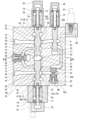
- FIG. 2 is a cross-sectional view taken along line II-II of FIG. 1
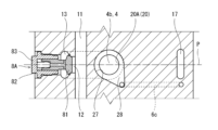
- FIG. 3 is a cross-sectional view taken along line III-III of FIG. 2
- FIG. FIG. 2 is a cross-sectional view taken along line IV-IV of FIG. 1
- 3 is a hydraulic circuit diagram including the fluid control device
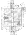
- FIG. It is a cross-sectional view of a fluid control device of a modification.
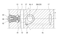
- FIG. 11 is a cross-sectional view of another modification of the fluid control device
- 1 is a hydraulic circuit diagram including a conventional fluid control device;
- FIG. 1 to 4 show a fluid control device 1 according to one embodiment
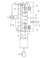
- FIG. 5 shows a hydraulic circuit diagram including the fluid control device 1.
- FIG. This fluid control device 1 is for controlling fluid supplied from a hydraulic pump 10a to a plurality of hydraulic actuators, and is arranged between the hydraulic pump 10a and the plurality of hydraulic actuators in a hydraulic circuit. be done.
- the fluid flowing in the hydraulic circuit is typically oil, but may be a liquid other than oil.
- all the hydraulic actuators are hydraulic actuators 10d that operate bi-directionally by supplying fluid.
- the hydraulic actuators 10d are double-acting cylinders, some or all of the hydraulic actuators 10d may be hydraulic motors.
- the hydraulic actuators may include hydraulic actuators (eg, single-acting cylinders) that are unidirectionally actuated by a supply of fluid.
- the number of hydraulic actuators 10d is five. From the viewpoint of simplification of the drawing, FIG. 5 shows only two hydraulic actuators 10d. However, the number of hydraulic actuators 10d is not limited to this, and can be changed as appropriate.
- the fluid control device 1 includes a plurality of spools 3 for the plurality of hydraulic actuators 10d and a housing 2 that slidably holds these spools 3.
- the fluid control device 1 may include a spool for the hydraulic actuator that operates in one direction by supplying fluid in addition to the spool 3. good.
- the number of spools 3 is the same as the number of hydraulic actuators 10d, but when two hydraulic pumps 10a are used, the fluids discharged from these hydraulic pumps 10a join together to form a hydraulic pressure. Two spools 3 may be used for one hydraulic actuator 10d so as to feed the actuator 10d.
- the spools 3 are parallel to each other and lined up in a specific direction.
- the spools 3 are arranged in a line such that the center lines of all the spools 3 are positioned on the same plane parallel to the specific direction.
- the centerlines of all spools 3 need not lie on the same plane parallel to the specific direction, and the centerlines of some spools 3 may be located away from the plane.
- the spools 3 may be arranged in two rows.
- the housing 2 includes a plurality of spool holes 20 into which spools 3 are respectively inserted. That is, the spool holes 20 are also arranged in the specific direction.
- the housing 2 also includes a pump passage 11 and a tank passage 16 extending in the specific direction. As shown in FIG. 5, the pump passage 11 forms a pump port 1a on the surface of the housing 2, and this pump port 1a is connected to the hydraulic pump 10a by pump piping.
- the tank passage 16 forms a tank port 1b on the surface of the housing 2, which is connected to the tank 10b by a tank pipe.
- the tank passage 16 branches into two branch passages 16a and 16b extending in the specific direction within the housing 2. As shown in FIGS.
- the pump passage 11 passes near the center of the spool 3, and the branch passages 16a and 16b of the tank passage 16 pass near both ends of the spool 3.
- the configurations of the pump passage 11 and the tank passage 16 can be changed as appropriate.
- the housing 2 includes a first supply/discharge passage 14 and a second supply/discharge passage 15 for each of the spools 3 . That is, the number of sets of the first supply/discharge passages 14 and the second supply/discharge passages 15 is the same as the number of spools 3 for the plurality of hydraulic actuators 10d that are bidirectionally operated by the supply of fluid.
- the first supply/discharge passage 14 and the second supply/discharge passage 15 form a pair of supply/discharge ports 1d on the surface of the housing 2, and these supply/discharge ports 1d are connected to the hydraulic actuator 10d by a pair of supply/discharge pipes. be.
- the two spools 3 are the separated spools 3A shown in FIG. 2, and the three spools 3 are the integrated spools 3B shown in FIG.
- the integrated spool 3B and the spaced spool 3A are alternately arranged. That is, the integrated spool 3B is positioned between the separate spools 3A.
- the arrangement of the integrated spool 3B and the spaced spool 3A is not limited to this, and for example, the spaced spool 3A may be adjacent to each other. Also, as long as the spool 3 includes at least one spaced spool 3A, the ratio of the numbers of the integrated spool 3B and the spaced spool 3A can be changed as appropriate. For example, all spools 3 may be separate spools 3A.
- the housing 2 includes a first pilot chamber 7A, a second pilot chamber 7B and a third pilot chamber 7C for each spaced spool 3A and a first pilot chamber 7D and a third pilot chamber 7D for each integral spool 3B. 2 pilot chambers 7E are included.
- the housing 2 includes a rectangular parallelepiped housing main body 2A extending in the specific direction, and a block 2B extending in the specific direction along one side of the housing main body 2A.
- the housing 2 also includes the same number of first covers 2C and second covers 2D as the spaced spool 3A, and the same number of first covers 2E and second covers 2F as the integral spool 3B.
- the configuration of the housing 2 is not limited to this, and can be changed as appropriate.
- a part of the first cover 2C and the first cover 2E may be integrated to form a block extending in the specific direction.
- the housing body 2A has a first side surface 2Aa and a second side surface 2Ab orthogonal to the axial direction of the spool 3, and a third side surface 2Ac and a fourth side surface 2Ad parallel to the specific direction and the axial direction of the spool 3.
- the block 2B is attached to the fourth side surface 2Ad
- the first covers 2C and 2E are attached to the first side surface 2Aa
- the second covers 2D and 2F are attached to the second side surface 2Ab.
- the pump passage 11 described above is formed between the spool hole 20 and the third side surface 2Ac, and the tank passage 16 described above is formed between the spool hole 20 and the fourth side surface 2Ad.
- the pump passage 11 may branch into two branch passages extending in the specific direction within the housing 2 . In this case, one branch path may be positioned between the spool hole 20 and the third side surface 2Ac, and the other branch path may be positioned between the spool hole 20 and the fourth side surface 2Ad.
- first and second supply/discharge passages 14 and 15 for the separate spool 3A and the first and second supply/discharge passages 14 and 15 for the integrated spool 3B are formed in the spool holes 20. and the third side surface 2Ac.
- first supply/discharge passage 14 and the second supply/discharge passage 15 for the integrated spool 3B may be formed between the spool hole 20 and the fourth side surface 2Ad.
- the spool hole 20 into which the separate spool 3A is inserted is the specific spool hole 20A, and the spool hole 20 into which the integrated spool 3B is inserted is the normal spool hole 20B.
- the first cover 2E has a container-like shape, and the first pilot chamber 7D is formed by closing the opening of the first cover 2E with the first side surface 2Aa of the housing body 2A.
- the second cover 2F has a container-like shape, and the second pilot chamber 7E is formed by closing the opening of the second cover 2F with the second side surface 2Ab of the housing body 2A.
- the normal spool hole 20B is a through hole formed in the housing body 2A so as to straddle the first pilot chamber 7D and the second pilot chamber 7E.
- the integrated spool 3B extends across the first supply/discharge passage 14 and the second supply/discharge passage 15, and has an end surface 3a facing the first pilot chamber 7D and an end surface 3b facing the second pilot chamber 7E. .
- the integrated spool 3B has a neutral position in which the first supply/discharge passage 14 and the second supply/discharge passage 15 are blocked from both the pump passage 11 and the tank passage 16, and a state in which the first supply/discharge passage 14 communicates with the pump passage 11.
- a first position (right side position in FIG. 5) where the second supply/discharge passage 15 communicates with the tank passage 16, and a first position where the first supply/discharge passage 14 communicates with the tank passage 16 and the second supply/discharge passage 15 communicates with the pump passage 11. It moves between the communicating second position (the left position in FIG. 5).
- the housing body 2A has a first inflow annular groove 2a, a second inflow annular groove 2b, a first intermediate annular groove 2c, and a second intermediate annular groove which are recessed radially outward from the normal spool hole 20B. 2d, a first outflow annular groove 2e and a second outflow annular groove 2f are formed.
- the first inflow annular groove 2a, the first intermediate annular groove 2c, and the first outflow annular groove 2e are arranged in this order from the center of the normal spool hole 20B toward the first cover 2E. 2b
- the second intermediate annular groove 2d and the second outflow annular groove 2f are arranged in this order from the center of the normal spool hole 20B toward the second cover 2F.
- a bridge passage 19 surrounding the pump passage 11 together with the normal spool hole 20B, and a communication hole 18 communicating the bridge passage 19 and the pump passage 11 are formed in the housing body 2A.
- the communication hole 18 extends from the pump passage 11 in the opposite direction to the normal spool hole 20B and connects to the center of the bridge passage 19. As shown in FIG.
- Both ends of the bridge passage 19 are connected to the first circular inflow groove 2a and the second circular inflow groove 2b. That is, the bridge passage 19 is connected to the normal spool hole 20B via the first annular groove 21 for inflow and the second annular groove 22 for inflow.
- a load check valve 8C that opens and closes the opening of the communication hole 18 with respect to the bridge passage 19 is provided in the housing body 2A.
- the load check valve 8C permits the flow from the pump passage 11 to the bridge passage 19, but prohibits the reverse flow.
- the load check valve 8C includes a body 83 fixed to the housing body 2A, a valve body 81 slidably held by the body 83, and a spring disposed between the body 83 and the valve body 81. 82 included. Since the structure of the load check valve 8C is well known, further detailed description will be omitted.
- the first supply/discharge passage 14 and the second supply/discharge passage 15 for the integrated spool 3B are connected to the first intermediate annular groove 2c and the second intermediate annular groove 2d, respectively, and the branch passages 16a and 16b of the tank passage 16 are respectively connected to the second intermediate annular grooves 2c and 2d. It is connected to the first outflow annular groove 2e and the second outflow annular groove 2f.
- the integrated spool 3B includes a plurality of land portions 31a-31f and a plurality of small diameter portions 32a-32e interposed between the land portions 31a-31f.
- the position where the integrated spool 3B moves from the neutral position toward the first cover 2E is the first position, and the position where it moves from the neutral position toward the second cover 2F is the second position.
- a spring 76 is arranged in the second pilot chamber 7E to apply a biasing force to the integrated spool 3B to maintain the integrated spool 3B in a neutral position.
- a spring 76 urges the integrated spool 3B directly toward the first cover 2E via a spring seat.
- a headed rod 75 is attached to the end face 3b of the integrated spool 3B, and the spring 76 moves the integrated spool 3B through the spring seat and the headed rod 75 toward the second cover 2F. energize.
- a first proportional solenoid valve 64 for the first pilot chamber 7D is attached to the first cover 2E
- a second proportional solenoid valve 65 (see FIG. 1) for the second pilot chamber 7E is attached to the block 2B. It is As shown in FIG. 5, the first proportional electromagnetic valve 64 outputs secondary pressure to the first pilot chamber 7D through the first pilot passage 6d, and the second proportional electromagnetic valve 65 outputs secondary pressure to the second pilot chamber 7D through the second pilot passage 6e. Output the secondary pressure to 7E. From the viewpoint of simplification of the drawing, the illustration of the second pilot passage 6e is omitted in FIG.
- FIG. 1 the structure around the spaced spool 3A and the specific spool hole 20A will be described in detail with reference to FIGS. 2 and 3.
- FIG. 1 the structure around the spaced spool 3A and the specific spool hole 20A will be described in detail with reference to FIGS. 2 and 3.
- FIG. 1 the structure around the spaced spool 3A and the specific spool hole 20A will be described in detail with reference to FIGS. 2 and 3.
- the first cover 2C has a container-like shape, and the first pilot chamber 7A is formed by closing the opening of the first cover 2C with the first side surface 2Aa of the housing body 2A.
- the second cover 2D has a container-like shape, and the second pilot chamber 7B is formed by closing the opening of the second cover 2D with the second side surface 2Ab of the housing body 2A.
- the first cover 2C is divided into a tubular portion and a lid portion, but the configuration of the first cover 2C is not limited to this.
- the specific spool hole 20A is a through hole formed in the housing body 2A so as to straddle the first pilot chamber 7A and the second pilot chamber 7B.
- the spaced spool 3A includes a first spool 4 and a second spool 5 axially spaced from each other within a specific spool bore 20A. A portion between the first spool 4 and the second spool 5 in the specific spool hole 20A constitutes the above-described third pilot chamber 7C.
- the end surface 4a of the first spool 4 on the side opposite to the second spool 5 faces the first pilot chamber 7A
- the end surface 4b on the second spool 5 side faces the third pilot chamber 7C
- the end face 5a of the second spool 5 opposite to the first spool 4 faces the second pilot chamber 7B
- the end face 5b on the first spool 4 side faces the third pilot chamber 7C.
- the first spool 4 has a neutral position in which the first supply/discharge passage 14 is blocked from both the pump passage 11 and the tank passage 16, and a neutral position in which the first supply/discharge passage 14 is disconnected from the tank passage 16 and communicated with the pump passage 11. 5) and a second position (right position in FIG. 5) in which the first supply/discharge passage 14 is blocked from the pump passage 11 and communicated with the tank passage 16. As shown in FIG.
- the second spool 5 has a neutral position in which the second supply/discharge passage 15 is blocked from both the pump passage 11 and the tank passage 16, and a neutral position in which the second supply/discharge passage 15 is disconnected from the pump passage 11 and communicates with the tank passage 16. 5) and a second position (left position in FIG. 5) in which the second supply/discharge passage 15 is blocked from the tank passage 16 and communicated with the pump passage 11. As shown in FIG.
- the first spool 4 communicates the first supply/discharge passage 14 with either the tank passage 16 or the pump passage 11.
- the second spool 5 connects the second supply/discharge passage 15 with the other of the tank passage 16 and the pump passage 11 .
- the housing body 2A has a first inflow annular groove 21, a first intermediate annular groove 23, and a first outflow annular groove 21, which are recessed radially outward from the specific spool hole 20A, in a region overlapping the first spool 4.
- An annular groove 25 is formed.
- the first inflow annular groove 21, the first intermediate annular groove 23, and the first outflow annular groove 25 are arranged in this order from the center of the specific spool hole 20A toward the first cover 2C.
- a second inflow annular groove 22, a second intermediate annular groove 24, and a second outflow annular groove which are recessed radially outward from the specific spool hole 20A, are formed in a region overlapping the second spool 5A. 26 are formed.
- the second inflow annular groove 22, the second intermediate annular groove 24, and the second outflow annular groove 26 are arranged in this order from the center of the specific spool hole 20A toward the second cover 2D.
- the housing body 2A is formed with a bridge passage 13 surrounding the pump passage 11 together with the specific spool hole 20A, and a communication hole 12 that communicates the bridge passage 13 and the pump passage 11 with each other.
- the communication hole 12 extends from the pump passage 11 in the opposite direction to the specific spool hole 20A and connects to the center of the bridge passage 13 .
- Both ends of the bridge passage 13 are connected to the first annular groove 21 for inflow and the second annular groove 22 for inflow. That is, the bridge passage 13 is connected to the specific spool hole 20A via the first annular inflow groove 21 and the second annular inflow groove 22 on both sides of the third pilot chamber 7C.
- a load check valve 8A that opens and closes the opening of the communication hole 12 with respect to the bridge passage 13 is provided in the housing main body 2A.
- the load check valve 8A permits the flow from the pump passage 11 to the bridge passage 13, but prohibits the reverse flow.
- the structure of the load check valve 8A is the same as the structure of the load check valve 8C described above.
- the first supply/discharge passage 14 and the second supply/discharge passage 15 for the spaced spool 3A are connected to the first intermediate annular groove 23 and the second intermediate annular groove 24, respectively, and the branch passages 16a and 16b of the tank passage 16 are respectively connected to the first and second intermediate annular grooves 23 and 24. It is connected to the first outflow annular groove 25 and the second outflow annular groove 26 .
- the first spool 4 includes a first land portion 45 that forms the end surface 4b and opens and closes the first inflow annular groove 21, and a second land portion 45 that is positioned between the first intermediate annular groove 23 and the first outflow annular groove 25. It includes a land portion 43 and a third land portion 41 that constitutes the end surface 4a and is located outside the specific spool hole 20A relative to the first annular groove 25 for outflow. Further, the first spool 4 includes a first small diameter portion 44 connecting the first land portion 45 and the second land portion 43 and a second small diameter portion 42 connecting the second land portion 43 and the third land portion 41. including. As shown in FIG. 2, the state in which the first land portion 45 closes the first annular groove 21 for inflow is the neutral position.
- the first land portion 45 opens the first annular groove 21 for inflow, and the first annular groove 21 for inflow communicates with the first intermediate annular groove 23 . do. This is the first position.
- the first intermediate annular groove 23 communicates with the first outflow annular groove 25 . This is the second position.
- the second spool 5 includes a first land portion 55 forming the end surface 5b positioned closer to the center of the specific spool hole 20A than the second inflow annular groove 22, and a second land opening and closing the second intermediate annular groove 24. and a third land portion 51 that forms the end surface 5a and is positioned outside the specific spool hole 20A relative to the second annular groove 26 for outflow.
- the second spool 5 includes a first small diameter portion 54 connecting the first land portion 55 and the second land portion 53, and a second small diameter portion 52 connecting the second land portion 53 and the third land portion 51. including. As shown in FIG. 2, the state in which the second land portion 53 closes the second intermediate annular groove 24 is the neutral position.
- the second land portion 53 opens the second intermediate annular groove 24 and the second intermediate annular groove 24 communicates with the second outflow annular groove 26 . .
- the second land portion 53 opens the second intermediate annular groove 24, and the second intermediate annular groove 24 opens the second inflow annular groove. 22. This is the second position.
- the shapes of the first spool 4 and the second spool 5 shown in FIG. 1 are merely examples, and the shapes can be changed as appropriate.
- the shape of the first spool 4 and the shape of the second spool 5 may be interchanged.
- a first spring 72 is arranged in the first pilot chamber 7A to apply a biasing force to the first spool 4 to maintain the first spool 4 in a neutral position.
- the first spring 72 urges the first spool 4 directly toward the second spool 5 via the spring seat.
- a headed rod 71 is attached to the end surface 4 a of the first spool 4 , and the first spring 72 connects the first spool 4 with the second spool 5 via the spring seat and the headed rod 71 . Force in the opposite direction.
- a second spring 74 is arranged in the second pilot chamber 7B to apply a biasing force to the second spool 5 to maintain the second spool 5 in the neutral position.
- the second spring 74 urges the second spool 5 directly toward the first spool 4 via the spring seat.
- a headed rod 73 is attached to the end surface 5 a of the second spool 5 , and the second spring 74 connects the second spool 5 with the first spool 4 via the spring seat and the headed rod 73 . Force in the opposite direction.
- the first spring 72 and the second spring 74 have the same configuration. That is, the biasing force applied to the first spool 4 by the first spring 72 and the biasing force applied to the second spool 5 by the second spring 74 are equal.
- the housing 2 has a first pilot passage 6a communicating with the first pilot chamber 7A, a second pilot passage 6b communicating with the second pilot chamber 7B, and a third pilot passage 6b communicating with the third pilot chamber 7C. 3 pilot passages 6c are included. From the viewpoint of simplification of the drawing, illustration of the first pilot passage 6a and the second pilot passage 6b is omitted in FIG.
- a first electromagnetic proportional valve 61 that outputs secondary pressure to the first pilot chamber 7A through the first pilot passage 6a is attached to the first cover 2C.
- the block 2B also includes a second electromagnetic proportional valve 62 (see FIG. 1) that outputs secondary pressure to the second pilot chamber 7B through the second pilot passage 6b, and a third pilot chamber 7C through the third pilot passage 6c.
- a third electromagnetic proportional valve 63 is attached to output the secondary pressure.
- the third electromagnetic proportional valve 63 is attached to the housing 2 at a position opposite to the load check valve 8A with respect to the specific spool hole 20A.
- the housing 2 includes a first proportional solenoid valve 61, a second proportional solenoid valve 62 and a third proportional solenoid valve 63 for the spaced spool 3A, and the above-described first proportional solenoid valve for the integrated spool 3B. It includes a primary pressure passage 60 connected with a proportional valve 64 and a second solenoid proportional valve 65 .
- the primary pressure passage 60 forms a primary pressure port 1c on the surface of the housing 2, and this primary pressure port 1c is connected to the sub-pump 10c by a primary pressure pipe.
- the housing 2 also includes a tank passage 66 that connects the solenoid proportional valves 61-65 with the tank passage 16 described above.
- the third electromagnetic proportional valve 63 is arranged with respect to a plane P perpendicular to the specific direction in which the spools 3 are arranged and passing through the center of the specific spool hole 20A. located away in the direction.
- the third electromagnetic proportional valve 63 may be positioned on the plane P.
- the third pilot passage 6c is located on the side opposite to the load check valve 8A with respect to the pump passage 11 in the specific direction and the direction perpendicular to the axial direction of the spaced spool 3A (that is, the left-right direction in FIG. 2). Located in However, the third pilot passage 6c may be positioned on the same side as the load check valve 8A with respect to the pump passage 11 in the horizontal direction of FIG.
- the housing main body 2A is formed with a central annular groove 27 that is recessed radially outward from the specific spool hole 20A between the first spool 4 and the second spool 5 . Furthermore, as shown in FIG. 3, the housing main body 2A is formed with a recess 28 that is contiguous with the central annular groove 27 and is recessed radially outward from the specific spool hole 20A. The third pilot passage 6c is connected to this recess 28. As shown in FIG. The central annular groove 27 and the recess 28 together with the portion between the first spool 4 and the second spool 5 in the specific spool hole 20A described above constitute the third pilot chamber 7C.
- the depression direction of the depression 28 is the side opposite to the load check valve 8A and oblique to the plane P described above when viewed from the center of the specific spool hole 20A. Therefore, the opening of the third pilot passage 6c to the third pilot chamber 7C is located away from the plane P. However, the opening of the third pilot passage 6c to the third pilot chamber 7C may be positioned on the plane P.
- the third pilot passage 6c extends downward in FIG. 2 from the recess 28, then bends rightward in FIG. 2, and then bends upward in FIG.
- the shape of the third pilot passage 6c can be changed as appropriate.
- the housing body 2A is formed with a regeneration passage 17 for guiding the fluid flowing from the second supply/discharge passage 15 into the specific spool hole 20A to the first supply/discharge passage 14.
- the regeneration passage 17 may be a passage for guiding the fluid flowing from the first supply/discharge passage 14 into the specific spool hole 20A to the second supply/discharge passage 15 .
- the regeneration passage 17 can be omitted. From the viewpoint of simplification of the drawing, FIG. 5 omits the illustration of the regeneration passage 17 and the configuration related thereto.
- the regeneration passage 17 is located on the opposite side of the specific spool hole 20A from the load check valve 8A.
- the regeneration passage 17 extends rightward in FIG. 2 from the second intermediate annular groove 24, bends downward in FIG. 2, and then bends leftward in FIG.
- the third pilot passage 6c partially overlaps the regeneration passage 17 when viewed from the specific direction. Therefore, the regeneration passage 17 and the third pilot passage 6c can be formed on the side opposite to the load check valve 8A with respect to the specific spool hole 20A.
- the housing main body 2A also slidably holds a spool 9 that allows or prohibits the flow of the fluid through the regeneration passage 17, ie, whether or not the fluid is regenerated.
- a cover 2G is attached to the second side surface 2Ab of the housing body 2A, and a pilot chamber 7F for operating the spool 9 is formed by this cover 2G.
- the housing main body 2A is provided with a regeneration valve 8B that permits the fluid to flow through the regeneration passage 17 only when the pressure in the second supply/discharge passage 15 is higher than the pressure in the first supply/discharge passage 14.
- the structure of the regeneration valve 8B is the same as that of the load check valves 8A and 8C.
- two spools are used to connect the first supply/discharge passage 14 and the second supply/discharge passage 15.
- the hydraulic actuator 10d can be operated bi-directionally. Further, since the first spool 4 and the second spool 5 are independent of each other, the first spool 4 can be moved according to the pressure difference between the first pilot chamber 7A and the third pilot chamber 7C. The second spool 5 can be moved according to the pressure difference between the second pilot chamber 7B and the third pilot chamber 7C. This allows independent metering control on either the meter-in side or the meter-out side when the hydraulic actuator 10d operates in either direction. Furthermore, since the number of pilot chambers is three, the number of electromagnetic proportional valves required can be reduced to three. That is, independent metering control is possible using three electromagnetic proportional valves for one hydraulic actuator 10d.
- the secondary pressure of the third electromagnetic proportional valve 63 is set to zero. , that is, a state in which the fluid can be discharged from the third pilot chamber 7C to the tank via the third proportional solenoid valve 63, the secondary pressure of the first proportional solenoid valve 61 and the second proportional solenoid valve 62 is raised from zero. At this time, if the secondary pressure of the first proportional solenoid valve 61 and the secondary pressure of the second proportional solenoid valve 62 are the same, independent metering control is not performed.
- the secondary pressure of the first electromagnetic proportional valve 61 is lower than the secondary pressure of the second electromagnetic proportional valve 62, meter-in control can be performed by the first electromagnetic proportional valve 61, and the second electromagnetic proportional valve 62 is lower than the secondary pressure of the first electromagnetic proportional valve 61, the second electromagnetic proportional valve 62 can perform meter-out control.
- the secondary pressure of the first electromagnetic proportional valve 61 and the first A state in which the secondary pressure of the two electromagnetic proportional valves 62 is zero that is, the fluid can be discharged from the first pilot chamber 7A to the tank via the first electromagnetic proportional valve 61 and the second pilot chamber 7A via the second electromagnetic proportional valve 62 If the secondary pressure of the third electromagnetic proportional valve 63 is increased from zero while the fluid can be discharged from the chamber 7B to the tank, the independent metering control is not performed.
- meter-out control can be performed by the first electromagnetic proportional valve 61, and if the secondary pressure of the second electromagnetic proportional valve 62 is greater than zero.
- meter-in control can be performed by the second electromagnetic proportional valve 62 .
- the opening of the third pilot passage 6c to the third pilot chamber 7C is offset from the center of the specific spool hole 20A in the specific direction in which the spools 3 are arranged.
- the degree of freedom in design is improved.
- the third pilot passage 6c is connected to the recess 28, so the connection position of the third pilot chamber 7C and the third pilot passage 6c can be set at any position.
- the depression 28 allows the opening of the third pilot passage 6c to be largely offset. .
- the third pilot passage 6c is located on the side opposite to the load check valve 8A with respect to the pump passage 11, so complication of passages formed in the housing 2 can be avoided.
- the integral spool 3B is positioned between the spaced spools 3A.
- the spaced-type spools 3A are adjacent to each other, three pilot passages and three electromagnetic proportional valves are required for each spaced-type spool 3A, so the pilot passages and the electromagnetic proportional valves are densely arranged. There is a need to.
- the integrated spool 3B is positioned between the separated spools 3A as in the present embodiment, such dense arrangement of the pilot passages and electromagnetic proportional valves can be alleviated.
- the central annular groove 27 may be omitted and the depression 28 may be directly depressed from the specific spool hole 20A.
- the recess 28 may also be omitted, and the third pilot passage 6c may be directly connected to the specific spool hole 20A.
- the first spool 4 includes a first land portion 48 that forms the end face 4b and opens and closes the first annular groove 21 for inflow, and a first land portion 48 that forms the end face 4a and the first annular groove for outflow. 25 and a small diameter portion 47 connecting the first land portion 48 and the second land portion 46 .
- the spool 9 is used for switching whether or not to regenerate the fluid, but it is also possible to configure so that regeneration is always performed as shown in FIG.
- a regeneration annular groove 29 is formed in the housing body 2A between the second intermediate annular groove 24 and the second outflow annular groove 26.
- the second small diameter portion 52 of the second spool 5 is provided with a land portion 56 located between the regeneration annular groove 29 and the second outflow annular groove 26 .
- the upstream end of the regeneration passage 17 is connected to an annular groove 29 for regeneration.
- the recess direction of the recess 28 may be oblique to the above-described plane P on the side of the load check valve 8A when viewed from the center of the specific spool hole 20A.
- the load check valve 8A may be omitted.
- the third pilot passage 6c is aligned with the center of the specific spool hole 20A in the direction orthogonal to the specific direction and the axial direction of the spaced type spool 3A (that is, the lateral direction in FIG. 2 or FIG. 5). If it is located on the side opposite to the bridge passage 13, it is possible to obtain the effect of avoiding complication of the passage formed in the housing 2 as in the above-described embodiment.
- the present disclosure provides a plurality of spools for a plurality of hydraulic actuators bi-directionally operated by fluid supply, a plurality of spool holes into which the plurality of spools are respectively inserted, pump passages, tank passages, and the plurality of spools.
- a housing including first and second supply and discharge passages for each, wherein at least one of the plurality of spools is a spaced apart type including a first spool and a second spool axially spaced apart from each other.
- the plurality of spool holes includes a specific spool hole into which the spaced-apart spool is inserted; and the first spool blocks the first supply/discharge passage from both the pump passage and the tank passage. Either the pump passage or the tank passage is communicated with the second spool, and the second spool blocks the second supply/discharge passage from both the pump passage and the tank passage.
- the housing includes a first pilot chamber facing the end face of the first spool opposite to the second spool, and a first pilot chamber facing the end face of the second spool opposite to the first spool. including two pilot chambers, a portion between the first spool and the second spool in the specific spool hole constitutes a third pilot chamber, and the housing includes a pilot passage communicating with the third pilot chamber;
- a fluid control device is provided.
- two spools can be used to bi-directionally operate the hydraulic actuator connected to the first supply/discharge passage and the second supply/discharge passage.
- the first spool and the second spool are independent of each other, the first spool can be moved according to the pressure difference between the first pilot chamber and the third pilot chamber, and the second pilot chamber and the second spool can be moved.
- the second spool can be moved according to the pressure difference with the 3 pilot chambers. This allows for independent metering control on either the meter-in or meter-out side when the hydraulic actuator is actuated in either direction.
- the number of pilot chambers is three, the number of electromagnetic proportional valves required can be reduced to three. That is, independent metering control is possible using three electromagnetic proportional valves for one hydraulic actuator.
- the plurality of spools are arranged in a specific direction, and the opening of the pilot passage to the third pilot chamber is separated in the specific direction from a plane perpendicular to the specific direction and passing through the center of the specific spool hole. position. According to this configuration, since the opening of the pilot passage to the third pilot chamber is offset from the center of the specific spool hole in the specific direction, the degree of freedom in designing the periphery of the specific spool hole is improved.
- the housing may include a depression that sharpens radially outward from the specific spool hole, and the pilot passage may be connected to the depression.
- the connection position between the third pilot chamber and the pilot passage can be set at an arbitrary position.
- the recess allows the pilot passage opening to be significantly offset.
- the plurality of spools are arranged in a specific direction, the pump passage extends in the specific direction, and the housing surrounds the pump passage together with the specific spool hole and the specific spool on both sides of the third pilot chamber.
- a bridge passage connected to a hole; and a communication hole communicating between the bridge passage and the pump passage.
- the pilot passage may be located on the side opposite to the load check valve with respect to the pump passage in the specific direction and in a direction perpendicular to the axial direction of the spaced spool. . According to this configuration, since the pilot passage is located on the opposite side of the load check valve with respect to the pump passage, complication of passages formed in the housing can be avoided.
- the housing is a regeneration passage located on the opposite side of the load check valve with respect to the specific spool hole, and flows into the specific spool hole from one of the first supply/discharge passage and the second supply/discharge passage.
- a regeneration passage for guiding fluid to the other of the first supply/discharge passage and the second supply/discharge passage may be included, and the pilot passage may overlap the regeneration passage when viewed from the specific direction. According to this configuration, the regeneration passage and the pilot passage can be formed on the opposite side of the load check valve with respect to the specific spool hole.
- the above fluid control device outputs secondary pressure to the third pilot chamber through the pilot passage, which is attached to the housing at a position opposite to the load check valve with respect to the specific spool hole.
- An electromagnetic proportional valve may be provided.
- the above fluid control device includes an electromagnetic proportional valve that is attached to the housing and outputs secondary pressure to the third pilot chamber through the pilot passage, and the electromagnetic proportional valve is perpendicular to the specific direction. It may be located on a plane passing through the center of the specific spool hole.
- the above fluid control device includes an electromagnetic proportional valve that is attached to the housing and outputs secondary pressure to the third pilot chamber through the pilot passage, and the electromagnetic proportional valve is perpendicular to the specific direction. It may be located away in the specific direction from a plane passing through the center of the specific spool hole.
- the plurality of spools may include a plurality of the spaced spools and an integrated spool located between the spaced spools and spanning the first supply/discharge passage and the second supply/discharge passage.
- each spaced spool requires 3 pilot passages and 3 proportional solenoid valves, so pilot passages and proportional solenoid valves must be densely arranged There is On the other hand, if the integrated spool is positioned between the separated spools, such a dense arrangement of the pilot passages and electromagnetic proportional valves can be alleviated.
- the plurality of spools are arranged in a specific direction, the pump passage extends in the specific direction, and the housing surrounds the pump passage together with the specific spool hole and the specific spool on both sides of the third pilot chamber.
- a bridge passage connected to a hole; and a communication hole communicating between the bridge passage and the pump passage. It may be located on the opposite side of the bridge passage with respect to the center of the particular spool hole.
- the pilot passage is located on the opposite side of the bridge passage with respect to the center of the specific spool hole, so it is possible to avoid complicating the passage formed in the housing.
Abstract
Selon l'invention, une bobine espacée (3A) comprenant une première bobine (4) et une deuxième bobine (5) espacées axialement l'une de l'autre est insérée dans un trou de bobine spécifique (20A) dans un boîtier (2). La première bobine (4) permet à un premier passage d'alimentation/de refoulement (14) de communiquer avec soit un passage de pompe (11) soit un passage de réservoir (16), et la deuxième bobine (5) permet à un second passage d'alimentation/de refoulement (15) de communiquer avec l'autre passage parmi le passage de pompe (11) et le passage de réservoir (16). Le boîtier (2) comprend une première chambre pilote (7A) faisant face à une surface d'extrémité (4a) de la première bobine (4) du côté opposé à la deuxième bobine (5), et une deuxième chambre pilote (7B) faisant face à une surface d'extrémité (5a) de la deuxième bobine (5) du côté opposé à la première bobine (4). La partie du trou de bobine spécifique (20A) entre la première bobine (4) et la deuxième bobine (5) constitue une troisième chambre pilote (7C), et le boîtier (2) comprend un passage pilote (6c) communiquant avec la troisième chambre pilote (7C).
Applications Claiming Priority (2)
| Application Number | Priority Date | Filing Date | Title |
|---|---|---|---|
| JP2022001648A JP2023101191A (ja) | 2022-01-07 | 2022-01-07 | 流体制御装置 |
| JP2022-001648 | 2022-01-07 |
Publications (1)
| Publication Number | Publication Date |
|---|---|
| WO2023132228A1 true WO2023132228A1 (fr) | 2023-07-13 |
Family
ID=87073602
Family Applications (1)
| Application Number | Title | Priority Date | Filing Date |
|---|---|---|---|
| PCT/JP2022/046831 WO2023132228A1 (fr) | 2022-01-07 | 2022-12-20 | Dispositif de régulation de liquide |
Country Status (2)
| Country | Link |
|---|---|
| JP (1) | JP2023101191A (fr) |
| WO (1) | WO2023132228A1 (fr) |
Cited By (1)
| Publication number | Priority date | Publication date | Assignee | Title |
|---|---|---|---|---|
| JP7474346B2 (ja) | 2020-10-13 | 2024-04-24 | 川崎重工業株式会社 | 方向・流量制御弁および液圧システム |
Citations (12)
| Publication number | Priority date | Publication date | Assignee | Title |
|---|---|---|---|---|
| JPS55149402A (en) * | 1979-03-26 | 1980-11-20 | Sperry Rand Corp | Transmission device |
| JPH048903A (ja) * | 1990-04-26 | 1992-01-13 | Kayaba Ind Co Ltd | 多機能弁 |
| JPH0483904A (ja) * | 1990-07-24 | 1992-03-17 | Daikin Ind Ltd | 流体制御装置 |
| JP2010532451A (ja) * | 2007-06-29 | 2010-10-07 | レイセオン・サルコス・エルエルシー | 非対称バルブ作動構造を持つ圧力制御バルブ |
| JP2011163466A (ja) * | 2010-02-10 | 2011-08-25 | Smc Corp | 減圧切換弁 |
| JP2016109163A (ja) * | 2014-12-03 | 2016-06-20 | 株式会社クボタ | 油圧回路 |
| WO2018025964A1 (fr) * | 2016-08-05 | 2018-02-08 | ナブテスコ株式会社 | Soupape de commande hydraulique et circuit de commande hydraulique |
| JP2019124227A (ja) * | 2018-01-11 | 2019-07-25 | 株式会社小松製作所 | 油圧回路 |
| JP2020070903A (ja) * | 2018-11-01 | 2020-05-07 | Kyb株式会社 | 流体圧制御装置 |
| JP2021169298A (ja) * | 2020-03-06 | 2021-10-28 | ザ・ボーイング・カンパニーThe Boeing Company | 操縦翼面アクチュエータアセンブリ、操縦翼面アクチュエータアセンブリ航空を含む機液圧システム、並びに関連する航空機及び方法 |
| WO2022080311A1 (fr) * | 2020-10-13 | 2022-04-21 | 川崎重工業株式会社 | Vanne de régulation de débit/distributeur et système de pression hydraulique |
| JP2022080073A (ja) * | 2020-11-17 | 2022-05-27 | 川崎重工業株式会社 | マルチ制御弁 |
-
2022
- 2022-01-07 JP JP2022001648A patent/JP2023101191A/ja active Pending
- 2022-12-20 WO PCT/JP2022/046831 patent/WO2023132228A1/fr unknown
Patent Citations (12)
| Publication number | Priority date | Publication date | Assignee | Title |
|---|---|---|---|---|
| JPS55149402A (en) * | 1979-03-26 | 1980-11-20 | Sperry Rand Corp | Transmission device |
| JPH048903A (ja) * | 1990-04-26 | 1992-01-13 | Kayaba Ind Co Ltd | 多機能弁 |
| JPH0483904A (ja) * | 1990-07-24 | 1992-03-17 | Daikin Ind Ltd | 流体制御装置 |
| JP2010532451A (ja) * | 2007-06-29 | 2010-10-07 | レイセオン・サルコス・エルエルシー | 非対称バルブ作動構造を持つ圧力制御バルブ |
| JP2011163466A (ja) * | 2010-02-10 | 2011-08-25 | Smc Corp | 減圧切換弁 |
| JP2016109163A (ja) * | 2014-12-03 | 2016-06-20 | 株式会社クボタ | 油圧回路 |
| WO2018025964A1 (fr) * | 2016-08-05 | 2018-02-08 | ナブテスコ株式会社 | Soupape de commande hydraulique et circuit de commande hydraulique |
| JP2019124227A (ja) * | 2018-01-11 | 2019-07-25 | 株式会社小松製作所 | 油圧回路 |
| JP2020070903A (ja) * | 2018-11-01 | 2020-05-07 | Kyb株式会社 | 流体圧制御装置 |
| JP2021169298A (ja) * | 2020-03-06 | 2021-10-28 | ザ・ボーイング・カンパニーThe Boeing Company | 操縦翼面アクチュエータアセンブリ、操縦翼面アクチュエータアセンブリ航空を含む機液圧システム、並びに関連する航空機及び方法 |
| WO2022080311A1 (fr) * | 2020-10-13 | 2022-04-21 | 川崎重工業株式会社 | Vanne de régulation de débit/distributeur et système de pression hydraulique |
| JP2022080073A (ja) * | 2020-11-17 | 2022-05-27 | 川崎重工業株式会社 | マルチ制御弁 |
Cited By (1)
| Publication number | Priority date | Publication date | Assignee | Title |
|---|---|---|---|---|
| JP7474346B2 (ja) | 2020-10-13 | 2024-04-24 | 川崎重工業株式会社 | 方向・流量制御弁および液圧システム |
Also Published As
| Publication number | Publication date |
|---|---|
| JP2023101191A (ja) | 2023-07-20 |
Similar Documents
| Publication | Publication Date | Title |
|---|---|---|
| US10156246B2 (en) | Directional control valve | |
| WO2023132228A1 (fr) | Dispositif de régulation de liquide | |
| US9200647B2 (en) | Pre- and post- compensational valve arrangement | |
| JP5984871B2 (ja) | 制御弁装置 | |
| US9222594B2 (en) | Directional valve equipped with pressure control | |
| WO2022107430A1 (fr) | Soupape multi-commande | |
| JP7474346B2 (ja) | 方向・流量制御弁および液圧システム | |
| JP6822930B2 (ja) | 流量制御弁 | |
| JP5164631B2 (ja) | 建設車両用バルブ装置 | |
| JP7423189B2 (ja) | 制御弁及び建設機械用油圧システム | |
| JP3558861B2 (ja) | トーナメント油路構成装置 | |
| JPH11230106A (ja) | 油圧制御装置 | |
| WO2018173843A1 (fr) | Soupape multisoupape de commande directionnelle | |
| JP6355606B2 (ja) | ロードセンシング回路におけるバルブ構造 | |
| US11460053B2 (en) | Open center control valve configured to combine fluid flow received from multiple sources | |
| US20100326382A1 (en) | Hydraulically operated valve control system and internal combustion engine comprising such a system | |
| WO2023176031A1 (fr) | Bloc de soupapes et dispositif de soupape à commandes multiples présentant ce dernier | |
| JP7385366B2 (ja) | 油圧制御装置 | |
| US11965532B2 (en) | Valve arrangement and valve group | |
| JP7397561B2 (ja) | 弁装置 | |
| JP4907143B2 (ja) | バルブ構造 | |
| JP2016200205A (ja) | 制御弁及びそれを備える流体圧制御装置 | |
| JP4566041B2 (ja) | 流量制御機構 | |
| JP2005061510A (ja) | 圧力補償弁付き方向制御弁装置 | |
| JP2012047307A (ja) | 切換弁 |
Legal Events
| Date | Code | Title | Description |
|---|---|---|---|
| 121 | Ep: the epo has been informed by wipo that ep was designated in this application |
Ref document number: 22918812 Country of ref document: EP Kind code of ref document: A1 |